Embed Size (px)
Citation preview
Great Planes® Model Manufacturing Co. guarantees this kit to be free from defects in both material and workmanship at the date of purchase. This warranty does not cover any component parts damaged by use or modifi cation. In no case shall Great Planes’ liability exceed the original cost of the purchased kit. Further, Great Planes reserves the right to change or modify this warranty without notice.
In that Great Planes has no control over the fi nal assembly or material used for fi nal assembly, no liability shall be assumed nor accepted for any damage resulting from the use by the user of the fi nal user-assembled product. By the act of using the user-assembled product, the user accepts all resulting liability.
If the buyer is not prepared to accept the liability associated with the use of this product, the buyer is advised to return
this kit immediately in new and unused condition to the place of purchase.
To make a warranty claim send the defective part or item to Hobby Services at the address below:
Hobby Services3002 N. Apollo Dr., Suite 1Champaign, IL 61822 USA
Include a letter stating your name, return shipping address, as much contact information as possible (daytime telephone number, fax number, e-mail address), a detailed description of the problem and a photocopy of the purchase receipt. Upon receipt of the package, the problem will be evaluated as quickly as possible.
READ THROUGH THIS MANUAL BEFORE STARTING CONSTRUCTION. IT CONTAINS IMPORTANT INSTRUCTIONS AND WARNINGS CONCERNING THE ASSEMBLY AND USE OF THIS MODEL.
Champaign, Illinois(217) 398-8970, Ext 5
WARRANTY
INSTRUCTION MANUAL
Entire Contents © Copyright 2008 GPMA1023Mnl1.0
Top Wingspan: 48 in [1220mm]Bottom Wingspan: 48 in [1220mm]
Total Wing Area: 1145 sq in [73.9 dm2]
Weight: 7–7.5 lb [3170–3400 g]Wing Loading: 14–15 oz/sq ft [43–46 g/dm
2]
Length: 58.5 in [1485mm]Radio: 4–5 ch.
Engine: .61 cu in [10cc] two-stroke,.70–.91 cu in [11.5–15.0cc] four-stroke,
RimFire™ .80 (50-55-500kV)
ARF .61-.91 SPORT BIPLANE
™
2
TABLE OF CONTENTS
INTRODUCTION ............................................................... 2SAFETY PRECAUTIONS ................................................. 3DECISIONS YOU MUST MAKE ........................................ 3 Engine Recommendations ......................................... 3 Motor/Battery/ESC Recommendations ...................... 3 Radio/Servo Recommendations ................................ 4ADDITIONAL ITEMS REQUIRED .................................... 6 Adhesives and Building Supplies ............................... 6 Optional Supplies and Tools ....................................... 6 Covering Tools ........................................................... 6BUILDING NOTES ............................................................ 6ORDERING REPLACEMENT PARTS .............................. 6KIT INSPECTION .............................................................. 7KIT CONTENTS ................................................................ 7PREPARATION ................................................................. 8ASSEMBLE THE FUSELAGE .......................................... 8 Test-Mount the Elevator and Rudder Servos ............. 8 Mount the Horizontal Stabilizer (Stab) ....................... 9 Hinge the Elevators and Rudder .............................. 11 Hook up the Elevator and Rudder ............................ 12 Mount the Main Landing Gear ................................. 14 Mount the Motor ....................................................... 14 Mount the Engine ..................................................... 16 Install the Fuel Tank ................................................. 17 Hook up the Throttle ................................................. 18 Mount the Cowl ........................................................ 18ASSEMBLE THE WINGS ................................................ 22 Mount the Aileron Servos ......................................... 22 Mount the Wings ...................................................... 23 Mark the Balance Point (C.G.) ................................. 26FINAL ASSEMBLY ......................................................... 27 Mount the Canopy .................................................... 27 Final Radio Installation ............................................. 27GET THE MODEL READY TO FLY ................................. 28 Apply the Decals ...................................................... 28 LiPo Battery Precautions ......................................... 28 Check the Control Directions ................................... 29 Set the Control Throws ............................................ 29 Assemble the Balance Stand ................................... 31 Balance the Model (C.G.)......................................... 31 Balance the Model Laterally ..................................... 32PREFLIGHT .................................................................... 32 Identify Your Model ................................................... 32 Charge the Batteries ................................................ 32 Balance Propellers ................................................... 32 Ground Check .......................................................... 33 Range Check ........................................................... 33ENGINE SAFETY PRECAUTIONS ................................. 33AMA SAFETY CODE (EXCERPTS) ..................................... 33CHECK LIST ................................................................... 34FLYING ............................................................................ 34 Takeoff ..................................................................... 34 Flight ....................................................................... 35 Landing .................................................................... 35
INTRODUCTION
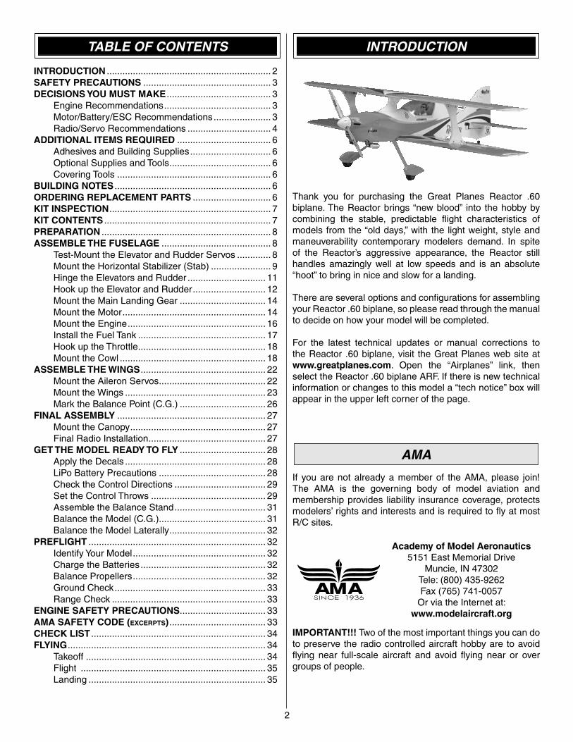
Thank you for purchasing the Great Planes Reactor .60 biplane. The Reactor brings “new blood” into the hobby by combining the stable, predictable fl ight characteristics of models from the “old days,” with the light weight, style and maneuverability contemporary modelers demand. In spite of the Reactor’s aggressive appearance, the Reactor still handles amazingly well at low speeds and is an absolute “hoot” to bring in nice and slow for a landing.
There are several options and confi gurations for assembling your Reactor .60 biplane, so please read through the manual to decide on how your model will be completed.
For the latest technical updates or manual corrections to the Reactor .60 biplane, visit the Great Planes web site at www.greatplanes.com. Open the “Airplanes” link, then select the Reactor .60 biplane ARF. If there is new technical information or changes to this model a “tech notice” box will appear in the upper left corner of the page.
AMA
If you are not already a member of the AMA, please join! The AMA is the governing body of model aviation and membership provides liability insurance coverage, protects modelers’ rights and interests and is required to fl y at most R/C sites.
Academy of Model Aeronautics5151 East Memorial Drive
Muncie, IN 47302Tele: (800) 435-9262Fax (765) 741-0057
Or via the Internet at:www.modelaircraft.org
IMPORTANT!!! Two of the most important things you can do to preserve the radio controlled aircraft hobby are to avoid fl ying near full-scale aircraft and avoid fl ying near or over groups of people.
3
PROTECT YOUR MODEL, YOURSELF & OTHERS...FOLLOW THESE
IMPORTANT SAFETY PRECAUTIONS
1. Your Reactor .60 Bipe should not be considered a toy, but rather a sophisticated, working model that functions very much like a full-size airplane. Because of its performance capabilities, the Reactor, if not assembled and operated correctly, could possibly cause injury to yourself or spectators and damage to property.
2. You must assemble the model according to the instructions. Do not alter or modify the model, as doing so may result in an unsafe or unfl yable model. In a few cases the instructions may differ slightly from the photos. In those instances the written instructions should be considered as correct.
3. You must take time to build straight, true and strong.
4. You must use an R/C radio system that is in good condition, a correctly sized engine, and other components as specifi ed in this instruction manual. All components must be correctly installed so that the model operates correctly on the ground and in the air. You must check the operation of the model and all components before every fl ight.
5. If you are not an experienced pilot or have not fl own this type of model before, we recommend that you get the assistance of an experienced pilot in your R/C club for your fi rst fl ights. If you’re not a member of a club, your local hobby shop has information about clubs in your area whose membership includes experienced pilots.
6. While this kit has been fl ight tested to exceed normal use, if the plane will be used for extremely high stress fl ying, such as racing, or if an engine larger than one in the recommended range is used, the modeler is responsible for taking steps to reinforce the high stress points and/or substituting hardware more suitable for the increased stress.
7. WARNING: The cowl, wheel pants and center wing brace included in this kit are made of fi berglass, the fi bers of which may cause eye, skin and respiratory tract irritation. Never blow into a part (wheel pant, cowl) to remove fi berglass dust, as the dust will blow back into your eyes. Always wear safety goggles, a particle mask and rubber gloves when grinding, drilling and sanding fi berglass parts. Vacuum the parts and the work area thoroughly after working with fi berglass parts.
We, as the kit manufacturer, provide you with a top quality, thoroughly tested kit and instructions, but ultimately the quality and fl yability of your fi nished model depends on how you build it; therefore, we cannot in any way guarantee the performance of your completed model, and no representations are expressed or implied as to the performance or safety of your completed model.
Remember: Take your time and follow the instructions to end up with a well-built model that is straight and true.
DECISIONS YOU MUST MAKE
Engine Recommendations
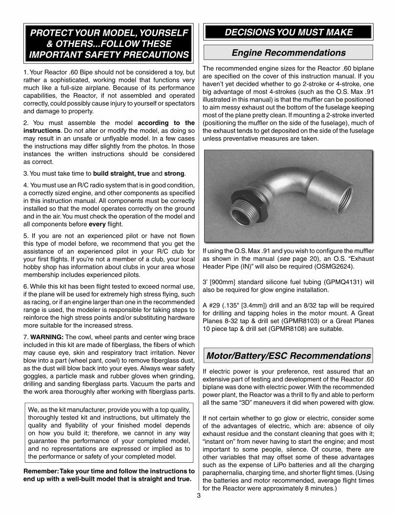
The recommended engine sizes for the Reactor .60 biplane are specifi ed on the cover of this instruction manual. If you haven’t yet decided whether to go 2-stroke or 4-stroke, one big advantage of most 4-strokes (such as the O.S. Max .91 illustrated in this manual) is that the muffl er can be positioned to aim messy exhaust out the bottom of the fuselage keeping most of the plane pretty clean. If mounting a 2-stroke inverted (positioning the muffl er on the side of the fuselage), much of the exhaust tends to get deposited on the side of the fuselage unless preventative measures are taken.
If using the O.S. Max .91 and you wish to confi gure the muffl er as shown in the manual (see page 20), an O.S. “Exhaust Header Pipe (IN)” will also be required (OSMG2624).
3’ [900mm] standard silicone fuel tubing (GPMQ4131) will also be required for glow engine installation.
A #29 (.135" [3.4mm]) drill and an 8/32 tap will be required for drilling and tapping holes in the motor mount. A Great Planes 8-32 tap & drill set (GPMR8103) or a Great Planes 10 piece tap & drill set (GPMR8108) are suitable.
Motor/Battery/ESC Recommendations
If electric power is your preference, rest assured that an extensive part of testing and development of the Reactor .60 biplane was done with electric power. With the recommended power plant, the Reactor was a thrill to fl y and able to perform all the same “3D” maneuvers it did when powered with glow.
If not certain whether to go glow or electric, consider some of the advantages of electric, which are: absence of oily exhaust residue and the constant cleaning that goes with it; “instant on” from never having to start the engine; and most important to some people, silence. Of course, there are other variables that may offset some of these advantages such as the expense of LiPo batteries and all the charging paraphernalia, charging time, and shorter fl ight times. (Using the batteries and motor recommended, average fl ight times for the Reactor were approximately 8 minutes.)
Following are the items illustrated in the instruction manual for equipping your Reactor .60 biplane with an electric motor:
POWER SYSTEM❏ Great Planes ElectriFly™ RimFire™ .80 (50-55-500kV)
electric motor (GPMG4740)❏ Great Planes ElectriFly Brushless Motor Mount for large
motors (GPMG1260)❏ Great Planes ElectriFly Silver Series 60A Brushless ESC
(GPMM1850)❏ (4) 3mm x 10mm socket-head cap screws (DUBQ3227)❏ (4) 3mm or #4 fl at washers (DUBQ3307)❏ (4) 3mm or #4 lock washers (DUBQ3285)❏ APC 15 x 8E propeller (APCQ4013)❏ APC 15 x 6E propeller (APCQ1505)
BATTERYA 3200mAh “6S” (6-cell, 22.2V) 20C LiPo (Lithium Polymer) battery is recommended. However, 6S batteries are not readily available, so two 3S (3-cell, 11.1V) batteries connected in series (via a Y-connector) are required to make one fl ight pack. This means two batteries will be required for the each “fl ight pack” desired. Also note the “20C” requirement which means that the batteries must be able to deliver current at a rate that is at least 20 times its rated capacity. This enables the motor to draw enough current to suitably fl y the plane.
The required battery adapter to convert two 3S packs into a 6S pack is the Great Planes U.S. Deans® 2 to 1 Series adapter.
❏ Great Planes ElectriFly™ 3200mAh 11.1V (3S), 20C LiPo battery (GPMP0623)
❏ Great Planes U.S. Deans 2 to 1 Series adapter (GPMM3143)
❏ Great Planes adhesive-backed Velcro® (for mounting the batteries) is also required (GPMQ4480)
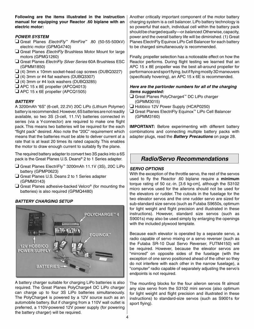
BATTERY CHARGING SETUP
A battery charger suitable for charging LiPo batteries is also required. The Great Planes PolyCharge4 DC LiPo charger can charge up to four 3S LiPo batteries simultaneously. The PolyCharge4 is powered by a 12V source such as an automobile battery. But if charging from a 110V wall outlet is preferred, a 110V-powered 12V power supply (for powering the battery charger) will be required.
Another critically important component of the motor battery charging system is a cell balancer. LiPo battery technology is so powerful that each, individual cell within the battery pack should be charged equally—or balanced. Otherwise, capacity, power and the overall battery life will be diminished. (1) Great Planes ElectriFly Equinox LiPo Cell Balancer for each battery to be charged simultaneously is recommended.
Finally, propeller selection has a noticeable effect on how the Reactor performs. During fl ight testing we learned that an APC 15 x 8E propeller was the best all-around propeller for performance and sport fl ying, but if fl ying mostly 3D maneuvers (specifi cally hovering), an APC 15 x 6E is recommended.
Here are the part/order numbers for all of the charging items suggested:❏ Great Planes PolyCharge4™ DC LiPo charger
(GPMM3015)❏ Hobbico 12V Power Supply (HCAP0250)❏ Great Planes ElectriFly Equinox™ LiPo Cell Balancer
(GPMM3160)
IMPORTANT: Before experimenting with different battery combinations and connecting multiple battery packs with adapter plugs, read the Battery Precautions on page 28.
Radio/Servo Recommendations
SERVO OPTIONSWith the exception of the throttle servo, the rest of the servos used to fl y the Reactor .60 biplane require a minimumtorque rating of 50 oz.-in. [3.6 kg-cm], although the S3102 micro servos used for the ailerons should not be used for the elevators or rudder. The cutouts in the fuselage for the two elevator servos and the one rudder servo are sized for sub-standard size servos (such as Futaba S9650s, optimum for light weight and fl ight precision and illustrated in these instructions). However, standard size servos (such as S9001s) may also be used simply by enlarging the openings with the included plywood template.
Because each elevator is operated by a separate servo, a radio capable of servo mixing or a servo reverser (such as the Futaba SR-10 Dual Servo Reverser, FUTM4150) will be required. However, because the elevator servos are “mirrored” on opposite sides of the fuselage (with the exception of one servo positioned ahead of the other so they do not interfere with each other in the narrow fuselage), a “computer” radio capable of separately adjusting the servo’s endpoints is not required.
The mounting blocks for the four aileron servos fi t almost any size servo from the S3102 mini servos (also optimum for light weight and fl ight precision and illustrated in these instructions) to standard-size servos (such as S9001s for sport fl ying).
4
5
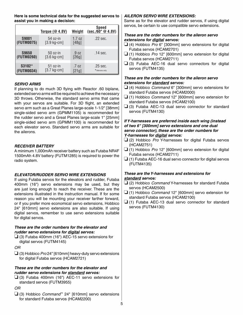
Here is some technical data for the suggested servos to assist you in making a decision:
WeightTorque (@ 4.8V)Speed
(sec./60° @ 4.8V)
S9001(FUTM0075)
54 oz-in[3.9 kg-cm]
1.7 oz[48g]
.22 sec.
S3102*(FUTM0034)
51 oz-in[3.7 kg-cm]
.7 oz[21g]
.25 sec.*
S9650(FUTM0260)
50 oz-in[3.6 kg-cm]
.9 oz[26g]
.14 sec.
Ailerons only
SERVO ARMSIf planning to do much 3D fl ying with Reactor .60 biplane, extended servo arms will be required to achieve the necessary 3D throws. Otherwise, the standard servo arms that came with your servos are suitable. For 3D fl ight, an extended servo arm such as a Great Planes large-scale 1-1/2" [38mm] single-sided servo arm (GPMM1105) is recommended for the rudder servo and a Great Planes large-scale 1" [25mm] single-sided servo arm (GPMM1100) is recommended for each elevator servo. Standard servo arms are suitable for the ailerons.
RECEIVER BATTERYA minimum 1,000mAh receiver battery such as Futaba NR4F 1500mAh 4.8V battery (FUTM1285) is required to power the radio system.
ELEVATOR/RUDDER SERVO WIRE EXTENSIONSIf using Futaba servos for the elevators and rudder, Futaba 400mm (16") servo extensions may be used, but they are just long enough to reach the receiver. These are the extensions illustrated in the instruction manual. If for some reason you will be mounting your receiver farther forward, or if you prefer more economical servo extensions, Hobbico 24" [610mm] servo extensions are also suitable. If using digital servos, remember to use servo extensions suitable for digital servos.
These are the order numbers for the elevator and rudder servo extensions for digital servos:❏ (3) Futaba 400mm (16") AEC-15 servo extensions for
digital servos (FUTM4145)
OR
❏ (3) Hobbico Pro 24" [610mm] heavy-duty servo extensions for digital Futaba servos (HCAM2721)
These are the order numbers for the elevator and rudder servo extensions for standard servos:❏ (3) Futaba 400mm (16") AEC-11 servo extensions for
standard servos (FUTM3955)
OR
❏ (3) Hobbico Command™ 24" [610mm] servo extensions for standard Futaba servos (HCAM2200)
AILERON SERVO WIRE EXTENSIONS:Same as for the elevator and rudder servos, if using digital servos, be certain to use compatible servo extensions.
These are the order numbers for the aileron servo extensions for digital servos:❏ (4) Hobbico Pro 6" [300mm] servo extensions for digital
Futaba servos (HCAM2701)❏ (1) Hobbico Pro 12" [600mm] servo extension for digital
Futaba servos (HCAM2711)❏ (3) Futaba AEC-16 dual servo connectors for digital
servos (FUTM4135)
These are the order numbers for the aileron servo extensions for standard servos:❏ (4) Hobbico Command 6" [300mm] servo extensions for
standard Futaba servos (HCAM2000)❏ (1) Hobbico Command 12" [600mm] servo extension for
standard Futaba servos (HCAM2100)❏ (3) Futaba AEC-13 dual servo connector for standard
servos (FUTM4130)
If Y-harnesses are preferred inside each wing (instead of two 6" [300mm] servo extensions and one dual servo connector), these are the order numbers for Y-harnesses for digital servos:❏ (2) Hobbico Pro Y-harnesses for digital Futaba servos
(HCAM2751)❏ (1) Hobbico Pro 12" [600mm] servo extension for digital
Futaba servos (HCAM2711)❏ (1) Futaba AEC-16 dual servo connector for digital servos
(FUTM4135)
These are the Y-harnesses and extensions forstandard servos:❏ (2) Hobbico Command Y-harnesses for standard Futaba
servos (HCAM2500)❏ (1) Hobbico Command 12" [600mm] servo extension for
standard Futaba servos (HCAM2100)❏ (1) Futaba AEC-13 dual servo connector for standard
servos (FUTM4130)
6
ADDITIONAL ITEMS REQUIRED
Adhesives and Building Supplies
❏ 1/4" [6mm] R/C foam rubber (HCAQ1000)❏ 1/2 oz. [15g] Thin Pro™ CA (GPMR6001)❏ 1/2 oz. [15g] Medium Pro CA+ (GPMR6007)❏ Pro 30-minute epoxy (GPMR6047)❏ Threadlocker thread locking cement (GPMR6060)❏ Silver solder w/fl ux (STAR2000)❏ Great Planes .050" Ballwrench for screws in aileron servo
hatches (GPMR8000)❏#1 Hobby knife (HCAR0105)❏#11 blades (5-pack, HCAR0211)❏ Drill bits: 1/16" [1.6mm], 3/32" [2.4mm], 1/8" [3.2mm], ❏ Small metal fi le
Optional Supplies and Tools
❏ Great Planes 1/5-Scale Sport pilot:GPMQ9015 Red, GPMQ9016 Blue,GPMQ9017 Yellow, GPMQ9018 Unpainted
❏ Robart Super Stand II (ROBP1402)❏ 8mm prop reamer (for propellers and included spinner –
GPMQ5007)❏ Tap handle (GPMR8120)❏ Stick-on segmented lead weights (GPMQ4485)❏ 2 oz. [57g] spray CA activator (GPMR6035)❏ R/C-56 canopy glue (JOZR5007)❏ CA applicator tips (HCAR3780)❏ CA debonder (GPMR6039)❏ Epoxy brushes (6, GPMR8060)❏ Mixing sticks (50, GPMR8055)❏ Mixing cups (GPMR8056)❏ Dead Center™ Engine Mount Hole Locator (GPMR8130)❏ Denatured alcohol (for epoxy clean up)❏ Kevlar thread (for horizontal stabilizer alignment)❏ Panel Line Pen (TOPQ2510)❏ Rotary tool such as Dremel❏ Hobby Heat™ micro torch (HCAR0755)
Covering Tools
The 21st Century covering iron and protective cover sock are recommended for tightening the covering or removing any wrinkles.❏ 21st Century® sealing iron (COVR2700) ❏ 21st Century iron cover (COVR2702)
BUILDING NOTES
• The Reactor .60 biplane ARF is factory-covered with Top Flite® MonoKote® fi lm. Should repairs ever be required, MonoKote can be patched with additional MonoKote purchased separately. MonoKote is packaged in six-foot rolls, but some hobby shops also sell it by the foot. If only a small piece of MonoKote is needed for a minor patch, perhaps a fellow modeler would give you some. MonoKote is applied with a model airplane covering iron, but in an emergency a regular iron could be used. A roll of MonoKote includes full instructions for application. Following are the colors used on this model and order numbers for six foot rolls.
White: TOPQ0204 Orange: TOPQ0202 Metallic Blue: TOPQ0402 Aluminum: TOPQ0205
• The stabilizer and wing incidences and engine thrust angles have been factory-built into this model. However, some technically-minded modelers may wish to check these measurements anyway. To view this information visit the web site at www.greatplanes.com and click on “Technical Data.” Due to manufacturing tolerances which will have little or no effect on the way your model will fl y, please expect slight deviations between your model and the published values.
ORDERING REPLACEMENT PARTS
Replacement parts for the Great Planes Reactor .60 bipe ARF are available using the order numbers in the Replacement Parts List that follows. The fastest, most economical service can be provided by your hobby dealer or mail-order company.
To locate a hobby dealer, visit the Great Planes web site at www.greatplanes.com. Choose “Where to Buy” and follow the instructions provided on the page to locate a U.S., Canadian or International dealer.
Parts may also be ordered directly from Hobby Services by calling (217) 398-0007, or via facsimile at (217) 398-7721, but full retail prices and shipping and handling charges will apply. Illinois and Nevada residents will also be charged sales tax. If ordering via fax, include a Visa® or MasterCard® number and expiration date for payment.
Mail parts orders and payments by personal check to:
Hobby Services3002 N Apollo Drive, Suite 1
Champaign IL 61822
Be certain to specify the order number exactly as listed in the Replacement Parts List. Payment by credit card or personal check only; no C.O.D.
If additional assistance is required for any reason contact Product Support by e-mail at [email protected], or by telephone at (217) 398-8970.
7
REPLACEMENT PARTS LIST
GPMA3340 ..... FuselageGPMA3341 ..... Top WingGPMA3342 ..... Bottom WingGPMA3343 ..... Horizontal StabilizerGPMA3344 ..... RudderGPMA3345 ..... CowlGPMA3346 ..... Landing GearGPMA3347 ..... WheelpantsGPMA3348 ..... CanopyGPMA3349 ..... StrutsGPMA3350 ..... DecalsGPMA3351 ..... Battery HatchGPMA3352 ..... Fuel Tank
NOTE: Full-size plans are not available. You can download a copy of this manual at www.greatplanes.com.
KIT INSPECTION
Before starting to build, take an inventory of this kit to make sure it is complete, and inspect the parts to make sure they are of acceptable quality. If any parts are missing or are not of acceptable quality, or if you need assistance with assembly, contact Product Support. When reporting defective or missing parts, use the part names exactly as they are written in the Kit Contents list.
Great Planes Product Support:3002 N Apollo Drive, Suite 1
Champaign, IL 61822Telephone: (217) 398-8970, ext. 5
Fax: (217) 398-7721E-mail: [email protected]
KIT CONTENTS
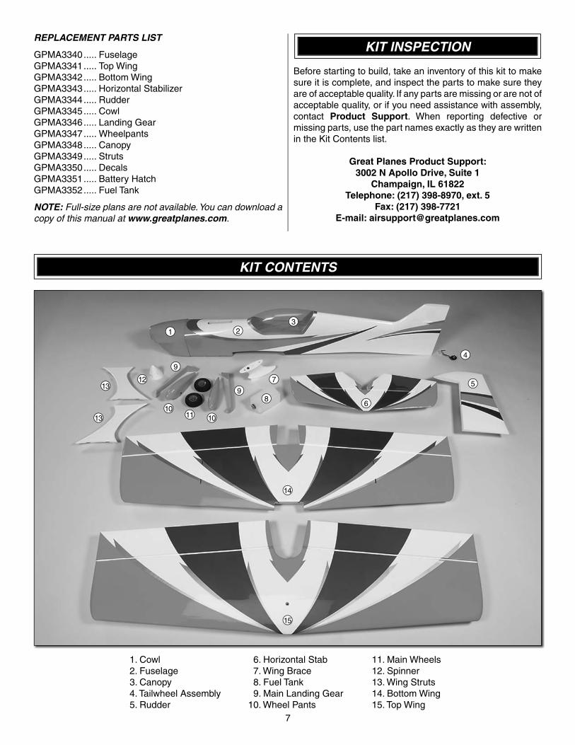
1. Cowl 2. Fuselage 3. Canopy 4. Tailwheel Assembly 5. Rudder
6. Horizontal Stab 7. Wing Brace 8. Fuel Tank 9. Main Landing Gear10. Wheel Pants
11. Main Wheels12. Spinner13. Wing Struts14. Bottom Wing15. Top Wing
1 23
4
5
68
7
1010
11
9
9
1213
13
14
15
8
PREPARATION
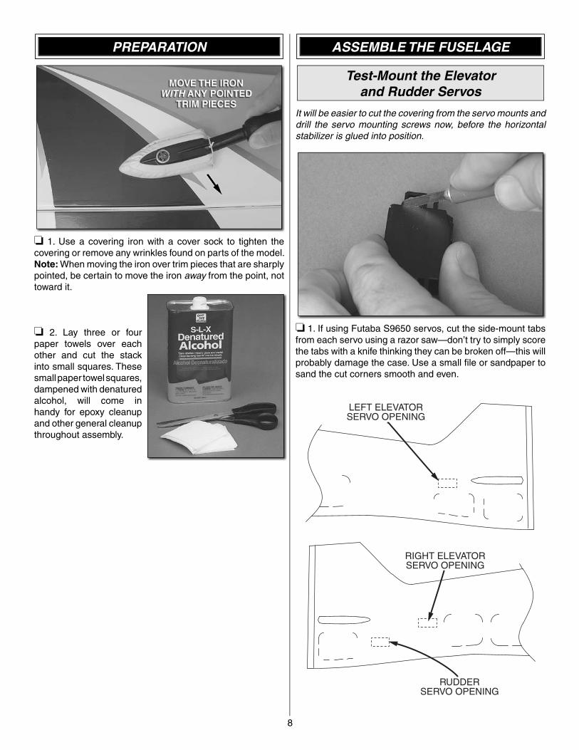
❏ 1. Use a covering iron with a cover sock to tighten the covering or remove any wrinkles found on parts of the model. Note: When moving the iron over trim pieces that are sharply pointed, be certain to move the iron away from the point, not toward it.
❏ 2. Lay three or four paper towels over each other and cut the stack into small squares. These small paper towel squares, dampened with denatured alcohol, will come in handy for epoxy cleanup and other general cleanup throughout assembly.
ASSEMBLE THE FUSELAGE
Test-Mount the Elevatorand Rudder Servos
It will be easier to cut the covering from the servo mounts and drill the servo mounting screws now, before the horizontal stabilizer is glued into position.
❏ 1. If using Futaba S9650 servos, cut the side-mount tabs from each servo using a razor saw—don’t try to simply score the tabs with a knife thinking they can be broken off—this will probably damage the case. Use a small fi le or sandpaper to sand the cut corners smooth and even.
LEFT ELEVATORSERVO OPENING
RIGHT ELEVATORSERVO OPENING
RUDDERSERVO OPENING
9
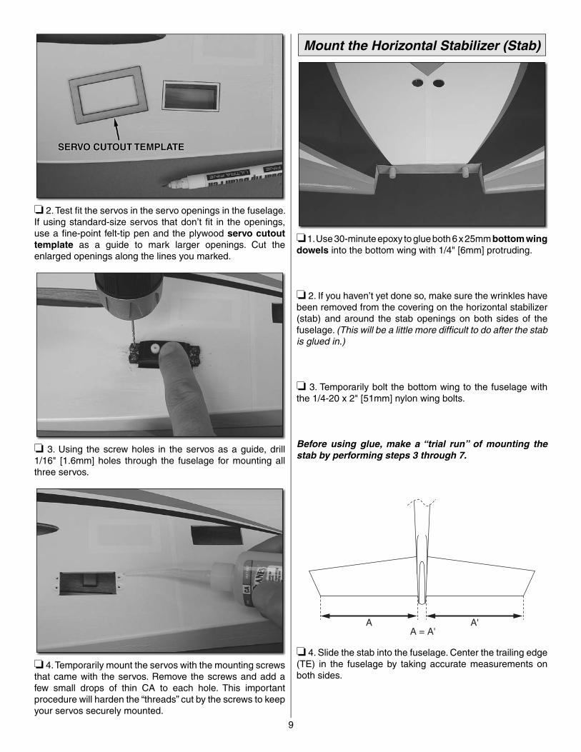
❏ 2. Test fi t the servos in the servo openings in the fuselage. If using standard-size servos that don’t fi t in the openings, use a fi ne-point felt-tip pen and the plywood servo cutout template as a guide to mark larger openings. Cut the enlarged openings along the lines you marked.
❏ 3. Using the screw holes in the servos as a guide, drill 1/16" [1.6mm] holes through the fuselage for mounting all three servos.
❏ 4. Temporarily mount the servos with the mounting screws that came with the servos. Remove the screws and add a few small drops of thin CA to each hole. This important procedure will harden the “threads” cut by the screws to keep your servos securely mounted.
Mount the Horizontal Stabilizer (Stab)
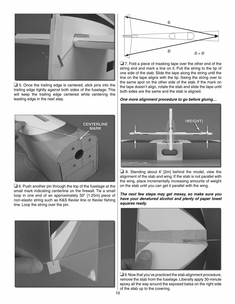
❏ 1. Use 30-minute epoxy to glue both 6 x 25mm bottom wing dowels into the bottom wing with 1/4" [6mm] protruding.
❏ 2. If you haven’t yet done so, make sure the wrinkles have been removed from the covering on the horizontal stabilizer (stab) and around the stab openings on both sides of the fuselage. (This will be a little more diffi cult to do after the stab is glued in.)
❏ 3. Temporarily bolt the bottom wing to the fuselage with the 1/4-20 x 2" [51mm] nylon wing bolts.
Before using glue, make a “trial run” of mounting the stab by performing steps 3 through 7.
A A'A = A'
❏ 4. Slide the stab into the fuselage. Center the trailing edge (TE) in the fuselage by taking accurate measurements on both sides.
10
❏ 5. Once the trailing edge is centered, stick pins into the trailing edge tightly against both sides of the fuselage. This will keep the trailing edge centered while centering the leading edge in the next step.
❏ 6. Push another pin through the top of the fuselage at the small mark indicating centerline on the fi rewall. Tie a small loop in one end of an approximately 50" [1.25m] piece of non-elastic string such as K&S Kevlar line or Kevlar fi shing line. Loop the string over the pin.
B
B' B = B'
❏ 7. Fold a piece of masking tape over the other end of the string end and mark a line on it. Pull the string to the tip of one side of the stab. Slide the tape along the string until the line on the tape aligns with the tip. Swing the string over to the same spot on the other side of the stab. If the mark on the tape doesn’t align, rotate the stab and slide the tape until both sides are the same and the stab is aligned.
One more alignment procedure to go before gluing…
❏ 8. Standing about 6’ [2m] behind the model, view the alignment of the stab and wing. If the stab is not parallel with the wing, place incrementally increasing amounts of weight on the stab until you can get it parallel with the wing.
The next few steps may get messy, so make sure you have your denatured alcohol and plenty of paper towel squares ready.
❏ 9. Now that you’ve practiced the stab alignment procedure, remove the stab from the fuselage. Liberally apply 30-minute epoxy all the way around the exposed balsa on the right side of the stab up to the covering.
11
❏ 10. Slide the stab into position, then partially out the other side, exposing the uncovered balsa on the other side of the stab. Apply more epoxy around the top and bottom of the stab, then slide it back into place. Use your fi nger or a piece of balsa or cardstock to thoroughly work epoxy back into the joint all the way around the top and bottom on both sides. Reinsert the pins into the trailing edge next to the fuselage. Use your paper towel squares to wipe away excess epoxy and use the pin and string and any weight that may have been necessary to align the stab with the wing. Do not disturb the model until the epoxy has hardened.
Hinge the Elevators and Rudders
1" [25mm]
CA HINGE 1" [25mm]
❏ 1. Cut ten 1" x 1" [25 x 25mm] CA hinges from the included CA hinge strip. Snip off the corners so they go in easier.
❏ 2. Stick a pin through the middle of three hinges. Without glue, fi t the hinges into the hinge slots in one side of the stab. (The T-pins will keep the hinges centered.)
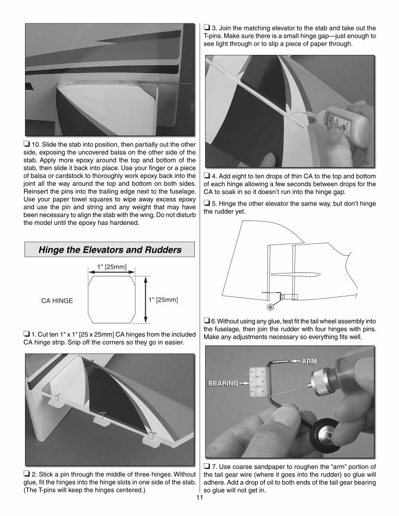
❏ 3. Join the matching elevator to the stab and take out the T-pins. Make sure there is a small hinge gap—just enough to see light through or to slip a piece of paper through.
❏ 4. Add eight to ten drops of thin CA to the top and bottom of each hinge allowing a few seconds between drops for the CA to soak in so it doesn’t run into the hinge gap.
❏ 5. Hinge the other elevator the same way, but don’t hinge the rudder yet.
❏ 6. Without using any glue, test fi t the tail wheel assembly into the fuselage, then join the rudder with four hinges with pins. Make any adjustments necessary so everything fi ts well.
❏ 7. Use coarse sandpaper to roughen the “arm” portion of the tail gear wire (where it goes into the rudder) so glue will adhere. Add a drop of oil to both ends of the tail gear bearing so glue will not get in.
12
❏ 8. Use a small metal ruler or straightedge to work 30-minute epoxy down into the slot in the fuselage for the tail gear bearing. Apply epoxy to the bearing, then fi t it into the slot. Wipe away excess epoxy.
❏ 9. Apply epoxy in the hole in the rudder for the tail gear wire and apply epoxy to the arm. Make sure the rudder hinges are in place, then join the rudder to the fuselage with the hinges. Wipe away any excess epoxy.
❏ 10. Remove the pins from the hinges and permanently join the rudder to the fuselage by gluing in the hinges with thin CA.
Hook Up the Elevator and Rudder
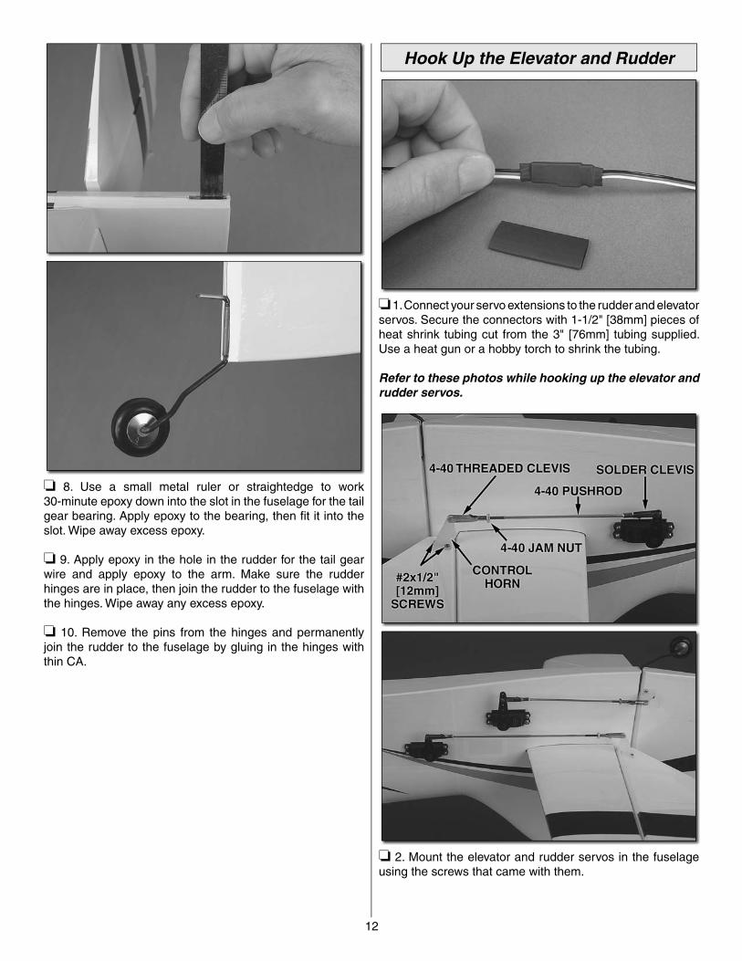
❏ 1. Connect your servo extensions to the rudder and elevator servos. Secure the connectors with 1-1/2" [38mm] pieces of heat shrink tubing cut from the 3" [76mm] tubing supplied. Use a heat gun or a hobby torch to shrink the tubing.
Refer to these photos while hooking up the elevator and rudder servos.
❏ 2. Mount the elevator and rudder servos in the fuselage using the screws that came with them.
13
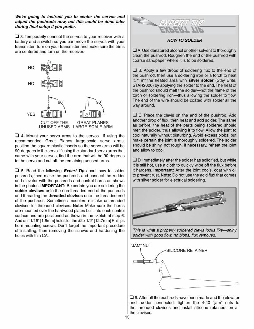
We’re going to instruct you to center the servos and adjust the pushrods now, but this could be done later during fi nal setup if you prefer.
❏ 3. Temporarily connect the servos to your receiver with a battery and a switch so you can move the servos with your transmitter. Turn on your transmitter and make sure the trims are centered and turn on the receiver.
90˚ 90˚
NO
NO
YES
CUT OFF THEUNUSED ARMS
GREAT PLANESLARGE-SCALE ARM
❏ 4. Mount your servo arms to the servos—if using the recommended Great Planes large-scale servo arms, position the square plastic inserts so the servo arms will be 90-degrees to the servo. If using the standard servo arms that came with your servos, fi nd the arm that will be 90-degrees to the servo and cut off the remaining unused arms.
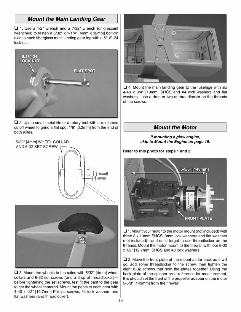
❏ 5. Read the following Expert Tip about how to solder pushrods, then make the pushrods and connect the rudder and elevator with the pushrods and control horns as shown in the photos. IMPORTANT: Be certain you are soldering the solder clevises onto the non-threaded end of the pushrods and threading the threaded clevises onto the threaded end of the pushrods. Sometimes modelers mistake unthreaded clevises for threaded clevises. Note: Make sure the horns are-mounted over the hardwood plates built into each control surface and are positioned as thown in the sketch at step 6. And drill 1/16" [1.6mm] holes for the #2 x 1/2" [12.7mm] Phillips horn mounting screws. Don’t forget the important procedure of installing, then removing the screws and hardening the holes with thin CA.
HOW TO SOLDER
❏ A. Use denatured alcohol or other solvent to thoroughly clean the pushrod. Roughen the end of the pushrod with coarse sandpaper where it is to be soldered.
❏ B. Apply a few drops of soldering fl ux to the end of the pushrod, then use a soldering iron or a torch to heat it. “Tin” the heated area with silver solder (Stay Brite, STAR2000) by applying the solder to the end. The heat of the pushrod should melt the solder—not the fl ame of the torch or soldering iron—thus allowing the solder to fl ow. The end of the wire should be coated with solder all the way around.
❏ C. Place the clevis on the end of the pushrod. Add another drop of fl ux, then heat and add solder. The same as before, the heat of the parts being soldered should melt the solder, thus allowing it to fl ow. Allow the joint to cool naturally without disturbing. Avoid excess blobs, but make certain the joint is thoroughly soldered. The solder should be shiny, not rough. If necessary, reheat the joint and allow to cool.
❏ D. Immediately after the solder has solidifi ed, but while it is still hot, use a cloth to quickly wipe off the fl ux before it hardens. Important: After the joint cools, coat with oil to prevent rust. Note: Do not use the acid fl ux that comes with silver solder for electrical soldering.
This is what a properly soldered clevis looks like—shiny solder with good fl ow, no blobs, fl ux removed.
“JAM” NUTSILICONE RETAINER
❏ 6. After all the pushrods have been made and the elevator and rudder connected, tighten the 4-40 “jam” nuts to the threaded clevises and install silicone retainers on all the clevises.
14
Mount the Main Landing Gear
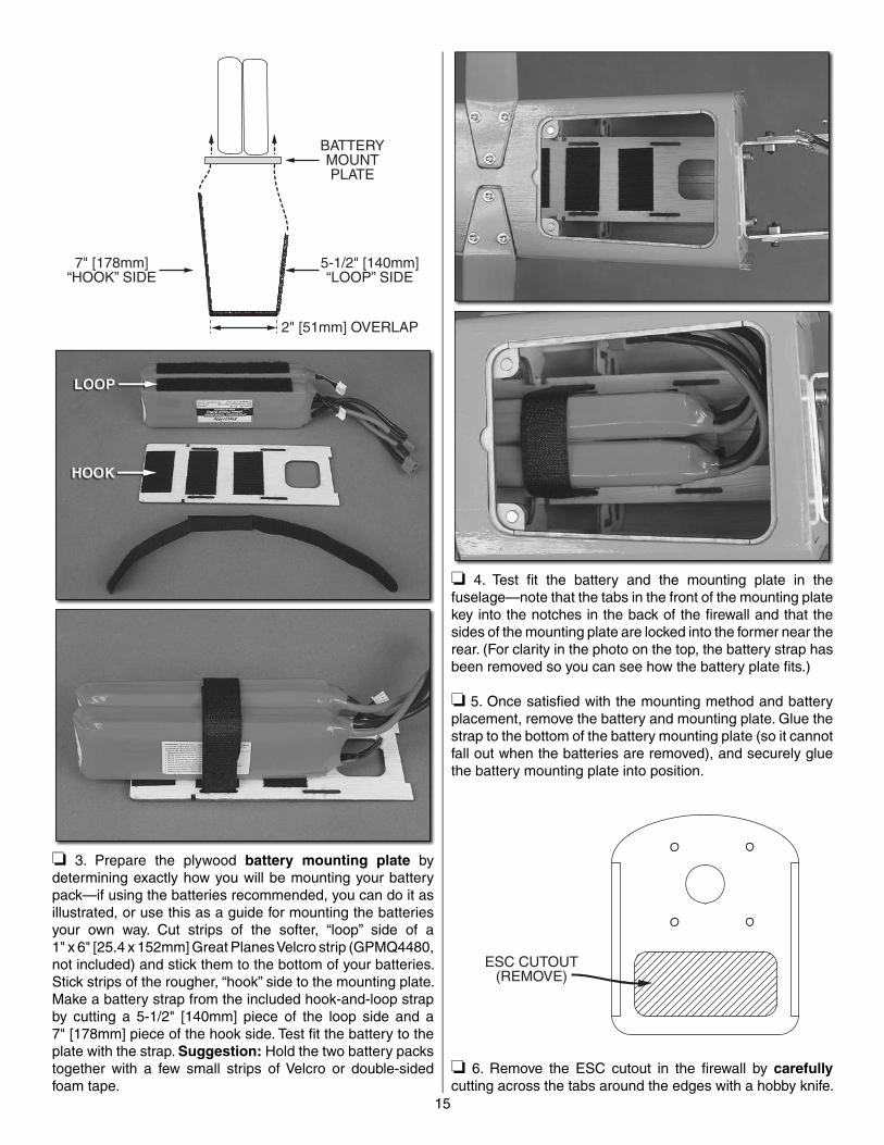
❏ 1. Use a 1/2" wrench and a 7/32" wrench (or crescent wrenches) to fasten a 5/32" x 1-1/4" [4mm x 32mm] bolt-on axle to each fi berglass main landing gear leg with a 5/16"-24 lock nut.
❏ 2. Use a small metal fi le or a rotary tool with a reinforced cutoff wheel to grind a fl at spot 1/8" [3.2mm] from the end of both axles.
5/32" [4mm] WHEEL COLLARAND 6-32 SET SCREW
❏ 3. Mount the wheels to the axles with 5/32" [4mm] wheel collars and 6-32 set screws (and a drop of threadlocker)—before tightening the set screws, test fi t the pant to the gear to get the wheel centered. Mount the pants to each gear with 4-40 x 1/2" [12.7mm] Phillips screws, #4 lock washers and fl at washers (and threadlocker).
❏ 4. Mount the main landing gear to the fuselage with six 4-40 x 3/4" [19mm] SHCS and #4 lock washers and fl at washers—use a drop or two of threadlocker on the threads of the screws.
Mount the Motor
If mounting a glow engine,skip to Mount the Engine on page 16.
Refer to this photo for steps 1 and 2.
❏ 1. Mount your motor to the motor mount (not included) with three 3 x 10mm SHCS, 3mm lock washers and fl at washers (not included)—and don’t forget to use threadlocker on the threads. Mount the motor mount to the fi rewall with four 8-32 x 1/2" [12.7mm] SHCS and #8 lock washers.
❏ 2. Move the front plate of the mount as far back as it will go, add some threadlocker to the screw, then tighten the eight 6-32 screws that hold the plates together. Using the back plate of the spinner as a reference for measurement, this should set the front of the propeller adapter on the motor 5-5/8" [143mm] from the fi rewall.
15
2" [51mm] OVERLAP
5-1/2" [140mm]“LOOP” SIDE
BATTERYMOUNTPLATE
7" [178mm]“HOOK” SIDE
❏ 3. Prepare the plywood battery mounting plate by determining exactly how you will be mounting your battery pack—if using the batteries recommended, you can do it as illustrated, or use this as a guide for mounting the batteries your own way. Cut strips of the softer, “loop” side of a 1" x 6" [25.4 x 152mm] Great Planes Velcro strip (GPMQ4480, not included) and stick them to the bottom of your batteries. Stick strips of the rougher, “hook” side to the mounting plate. Make a battery strap from the included hook-and-loop strap by cutting a 5-1/2" [140mm] piece of the loop side and a 7" [178mm] piece of the hook side. Test fi t the battery to the plate with the strap. Suggestion: Hold the two battery packs together with a few small strips of Velcro or double-sided foam tape.
❏ 4. Test fi t the battery and the mounting plate in the fuselage—note that the tabs in the front of the mounting plate key into the notches in the back of the fi rewall and that the sides of the mounting plate are locked into the former near the rear. (For clarity in the photo on the top, the battery strap has been removed so you can see how the battery plate fi ts.)
❏ 5. Once satisfi ed with the mounting method and battery placement, remove the battery and mounting plate. Glue the strap to the bottom of the battery mounting plate (so it cannot fall out when the batteries are removed), and securely glue the battery mounting plate into position.
ESC CUTOUT(REMOVE)
❏ 6. Remove the ESC cutout in the fi rewall by carefullycutting across the tabs around the edges with a hobby knife.
16
❏ 7. Glue together the plywood ESC mount and glue the plywood screw doublers to the bottom of the mount. Mount the ESC to the mount with three #4 x 1/2" [12.7mm] screws and #4 fl at washers.
❏ 8. Securely glue the ESC mount to the fi rewall. Connect the motor wires to the motor.
IMPORTANT: Before connecting your batteries to power up the motor in the following step, be certain NOT to have a propeller mounted to the motor and read the Battery Precautions on page 28.
❏ 9. Temporarily connect your receiver, on/off switch, receiver battery and motor batteries so you can power the motor to make sure it is hooked up correctly. Turn on the radio and use the throttle stick on your transmitter to make sure the motor turns in the correct direction (counter-clockwise when viewed from the front). If the motor does not turn the correct direction, switch any two motor and ESC wires with each other to reverse the direction. Use nylon tie wraps or electrical tape to secure all the wires and make certain they will not rub on the motor or motor shaft.
Mount the Engine
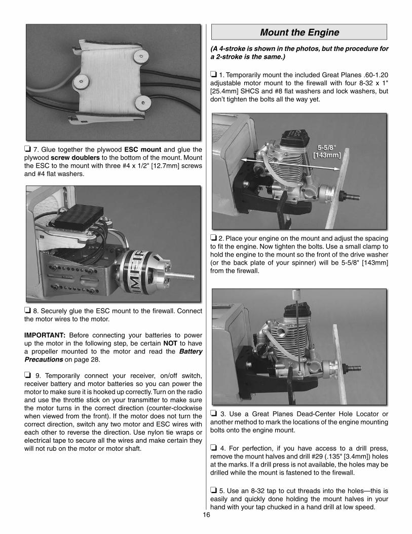
(A 4-stroke is shown in the photos, but the procedure for a 2-stroke is the same.)
❏ 1. Temporarily mount the included Great Planes .60-1.20 adjustable motor mount to the fi rewall with four 8-32 x 1" [25.4mm] SHCS and #8 fl at washers and lock washers, but don’t tighten the bolts all the way yet.
❏ 2. Place your engine on the mount and adjust the spacing to fi t the engine. Now tighten the bolts. Use a small clamp to hold the engine to the mount so the front of the drive washer (or the back plate of your spinner) will be 5-5/8" [143mm] from the fi rewall.
❏ 3. Use a Great Planes Dead-Center Hole Locator or another method to mark the locations of the engine mounting bolts onto the engine mount.
❏ 4. For perfection, if you have access to a drill press, remove the mount halves and drill #29 (.135" [3.4mm]) holes at the marks. If a drill press is not available, the holes may be drilled while the mount is fastened to the fi rewall.
❏ 5. Use an 8-32 tap to cut threads into the holes—this is easily and quickly done holding the mount halves in your hand with your tap chucked in a hand drill at low speed.
17
O.S. .61FX
O.S. FS91 II,O.S. FS81
O.S. FS91 II PUMP
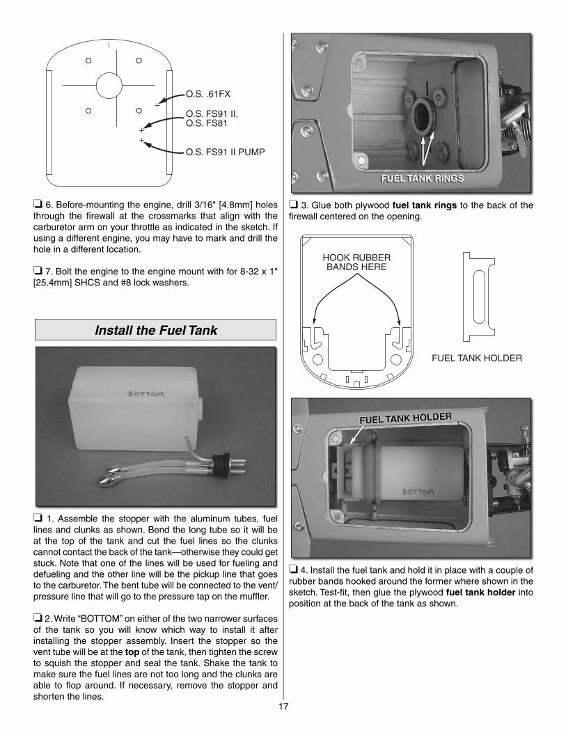
❏ 6. Before-mounting the engine, drill 3/16" [4.8mm] holes through the fi rewall at the crossmarks that align with the carburetor arm on your throttle as indicated in the sketch. If using a different engine, you may have to mark and drill the hole in a different location.
❏ 7. Bolt the engine to the engine mount with for 8-32 x 1" [25.4mm] SHCS and #8 lock washers.
Install the Fuel Tank
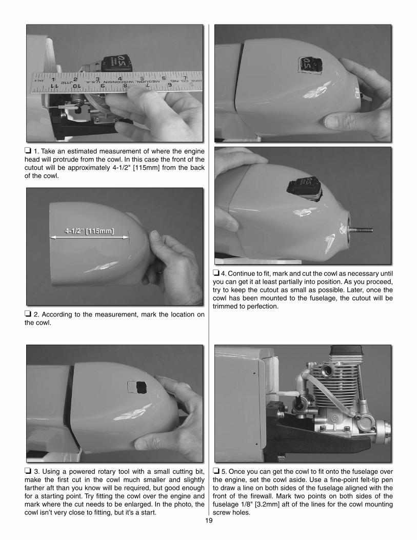
❏ 1. Assemble the stopper with the aluminum tubes, fuel lines and clunks as shown. Bend the long tube so it will be at the top of the tank and cut the fuel lines so the clunks cannot contact the back of the tank—otherwise they could get stuck. Note that one of the lines will be used for fueling and defueling and the other line will be the pickup line that goes to the carburetor. The bent tube will be connected to the vent/pressure line that will go to the pressure tap on the muffl er.
❏ 2. Write “BOTTOM” on either of the two narrower surfaces of the tank so you will know which way to install it after installing the stopper assembly. Insert the stopper so the vent tube will be at the top of the tank, then tighten the screw to squish the stopper and seal the tank. Shake the tank to make sure the fuel lines are not too long and the clunks are able to fl op around. If necessary, remove the stopper and shorten the lines.
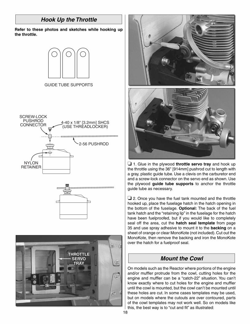
❏ 3. Glue both plywood fuel tank rings to the back of the fi rewall centered on the opening.
FUEL TANK HOLDER
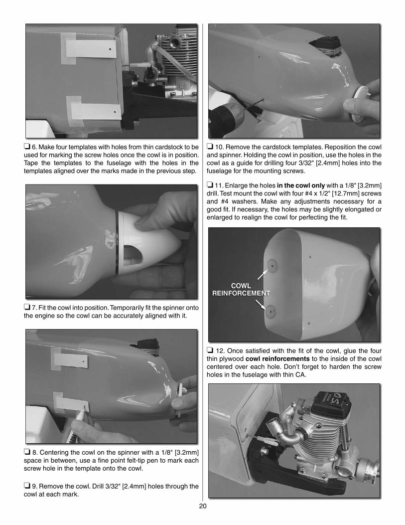
HOOK RUBBERBANDS HERE
❏ 4. Install the fuel tank and hold it in place with a couple of rubber bands hooked around the former where shown in the sketch. Test-fi t, then glue the plywood fuel tank holder into position at the back of the tank as shown.
18
Hook Up the Throttle
Refer to these photos and sketches while hooking up the throttle.
GUIDE TUBE SUPPORTS
SCREW-LOCKPUSHROD
CONNECTOR4-40 x 1/8" [3.2mm] SHCS(USE THREADLOCKER)
2-56 PUSHROD
NYLONRETAINER
❏ 1. Glue in the plywood throttle servo tray and hook up the throttle using the 36" [914mm] pushrod cut to length with a gray, plastic guide tube. Use a clevis on the carburetor end and a screw-lock connector on the servo end as shown. Use the plywood guide tube supports to anchor the throttle guide tube as necessary.
❏ 2. Once you have the fuel tank mounted and the throttle hooked up, place the fuselage hatch in the hatch opening in the bottom of the fuselage. Optional: The back of the fuel tank hatch and the “retaining lip” in the fuselage for the hatch have been fuelproofed, but if you would like to completely seal off the area, cut the hatch seal template from page 35 and use spray adhesive to mount it to the backing on a sheet of orange or clear MonoKote (not included). Cut out the MonoKote, then remove the backing and iron the MonoKote over the hatch for a fuelproof seal.
Mount the Cowl
On models such as the Reactor where portions of the engine and/or muffl er protrude from the cowl, cutting holes for the engine and muffl er can be a “catch-22” situation. You can’t know exactly where to cut holes for the engine and muffl er until the cowl is mounted, but the cowl can’t be mounted until these holes are cut. In some cases templates may be used, but on models where the cutouts are over contoured, parts of the cowl templates may not work well. So on models like this, the best way is to “cut and fi t” as illustrated:
19
❏ 1. Take an estimated measurement of where the engine head will protrude from the cowl. In this case the front of the cutout will be approximately 4-1/2" [115mm] from the back of the cowl.
❏ 2. According to the measurement, mark the location on the cowl.
❏ 3. Using a powered rotary tool with a small cutting bit, make the fi rst cut in the cowl much smaller and slightly farther aft than you know will be required, but good enough for a starting point. Try fi tting the cowl over the engine and mark where the cut needs to be enlarged. In the photo, the cowl isn’t very close to fi tting, but it’s a start.
❏ 4. Continue to fi t, mark and cut the cowl as necessary until you can get it at least partially into position. As you proceed, try to keep the cutout as small as possible. Later, once the cowl has been mounted to the fuselage, the cutout will be trimmed to perfection.
❏ 5. Once you can get the cowl to fi t onto the fuselage over the engine, set the cowl aside. Use a fi ne-point felt-tip pen to draw a line on both sides of the fuselage aligned with the front of the fi rewall. Mark two points on both sides of the fuselage 1/8" [3.2mm] aft of the lines for the cowl mounting screw holes.
20
❏ 6. Make four templates with holes from thin cardstock to be used for marking the screw holes once the cowl is in position. Tape the templates to the fuselage with the holes in the templates aligned over the marks made in the previous step.
❏ 7. Fit the cowl into position. Temporarily fi t the spinner onto the engine so the cowl can be accurately aligned with it.
❏ 8. Centering the cowl on the spinner with a 1/8" [3.2mm] space in between, use a fi ne point felt-tip pen to mark each screw hole in the template onto the cowl.
❏ 9. Remove the cowl. Drill 3/32" [2.4mm] holes through the cowl at each mark.
❏ 10. Remove the cardstock templates. Reposition the cowl and spinner. Holding the cowl in position, use the holes in the cowl as a guide for drilling four 3/32" [2.4mm] holes into the fuselage for the mounting screws.
❏ 11. Enlarge the holes in the cowl only with a 1/8" [3.2mm] drill. Test mount the cowl with four #4 x 1/2" [12.7mm] screws and #4 washers. Make any adjustments necessary for a good fi t. If necessary, the holes may be slightly elongated or enlarged to realign the cowl for perfecting the fi t.
❏ 12. Once satisfi ed with the fi t of the cowl, glue the four thin plywood cowl reinforcements to the inside of the cowl centered over each hole. Don’t forget to harden the screw holes in the fuselage with thin CA.
21
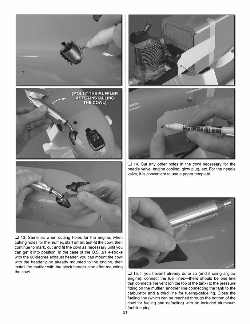
❏ 13. Same as when cutting holes for the engine, when cutting holes for the muffl er, start small, test-fi t the cowl, then continue to mark, cut and fi t the cowl as necessary until you can get it into position. In the case of the O.S. .91 4-stroke with the 90-degree exhaust header, you can mount the cowl with the header pipe already mounted to the engine, then install the muffl er with the stock header pipe after mounting the cowl.
❏ 14. Cut any other holes in the cowl necessary for the needle valve, engine cooling, glow plug, etc. For the needle valve, it is convenient to use a paper template.
❏ 15. If you haven’t already done so (and if using a glow engine), connect the fuel lines—there should be one line that connects the vent (on the top of the tank) to the pressure fi tting on the muffl er, another line connecting the tank to the carburetor and a third line for fueling/defueling. Close the fueling line (which can be reached through the bottom of the cowl for fueling and defueling) with an included aluminum fuel line plug.
22
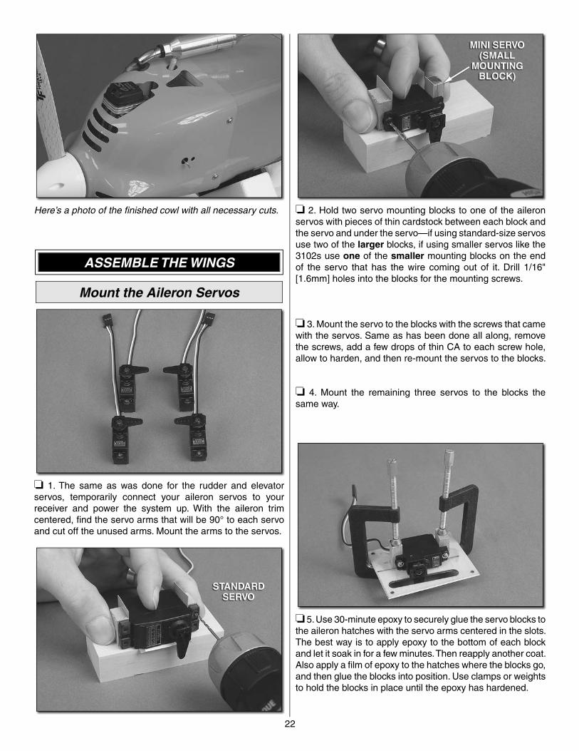
Here’s a photo of the fi nished cowl with all necessary cuts.
ASSEMBLE THE WINGS
Mount the Aileron Servos
❏ 1. The same as was done for the rudder and elevator servos, temporarily connect your aileron servos to your receiver and power the system up. With the aileron trim centered, fi nd the servo arms that will be 90° to each servo and cut off the unused arms. Mount the arms to the servos.
❏ 2. Hold two servo mounting blocks to one of the aileron servos with pieces of thin cardstock between each block and the servo and under the servo—if using standard-size servos use two of the larger blocks, if using smaller servos like the 3102s use one of the smaller mounting blocks on the end of the servo that has the wire coming out of it. Drill 1/16" [1.6mm] holes into the blocks for the mounting screws.
❏ 3. Mount the servo to the blocks with the screws that came with the servos. Same as has been done all along, remove the screws, add a few drops of thin CA to each screw hole, allow to harden, and then re-mount the servos to the blocks.
❏ 4. Mount the remaining three servos to the blocks the same way.
❏ 5. Use 30-minute epoxy to securely glue the servo blocks to the aileron hatches with the servo arms centered in the slots. The best way is to apply epoxy to the bottom of each block and let it soak in for a few minutes. Then reapply another coat. Also apply a fi lm of epoxy to the hatches where the blocks go, and then glue the blocks into position. Use clamps or weights to hold the blocks in place until the epoxy has hardened.
23
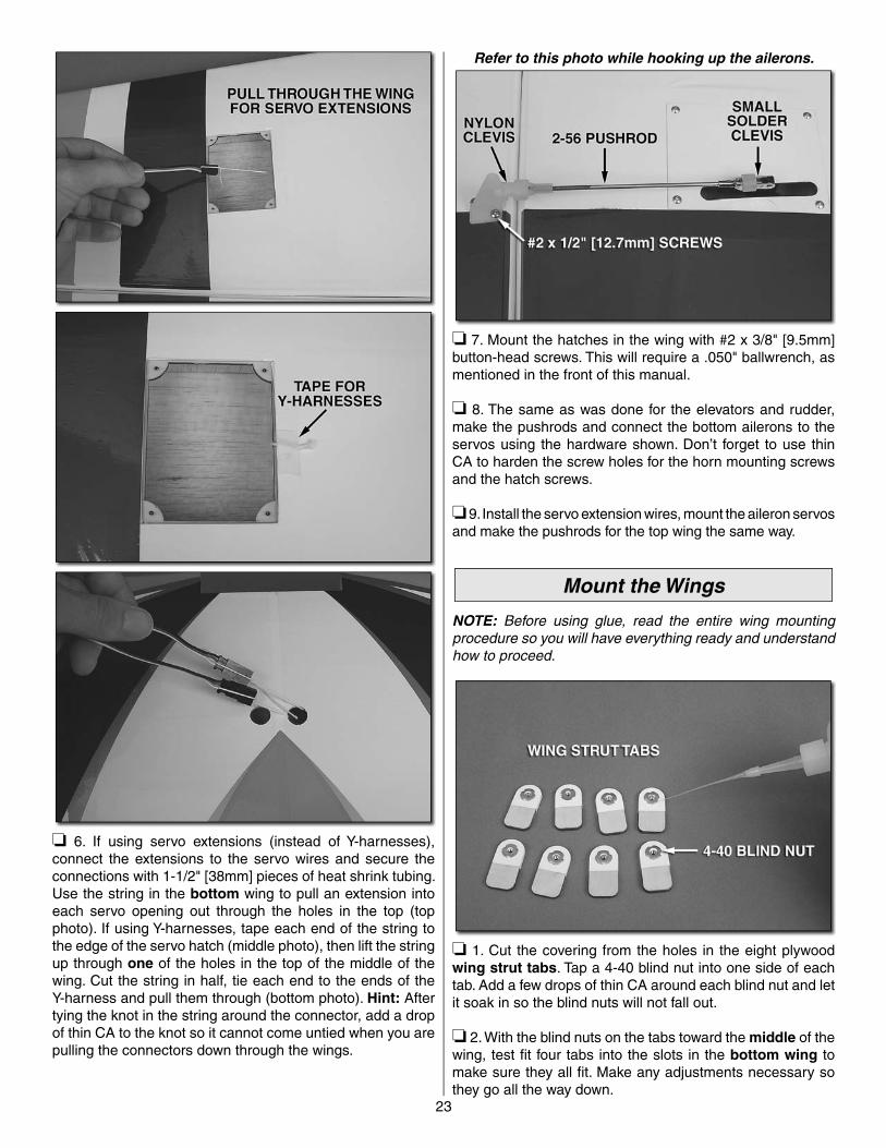
❏ 6. If using servo extensions (instead of Y-harnesses), connect the extensions to the servo wires and secure the connections with 1-1/2" [38mm] pieces of heat shrink tubing. Use the string in the bottom wing to pull an extension into each servo opening out through the holes in the top (top photo). If using Y-harnesses, tape each end of the string to the edge of the servo hatch (middle photo), then lift the string up through one of the holes in the top of the middle of the wing. Cut the string in half, tie each end to the ends of the Y-harness and pull them through (bottom photo). Hint: After tying the knot in the string around the connector, add a drop of thin CA to the knot so it cannot come untied when you are pulling the connectors down through the wings.
Refer to this photo while hooking up the ailerons.
❏ 7. Mount the hatches in the wing with #2 x 3/8" [9.5mm] button-head screws. This will require a .050" ballwrench, as mentioned in the front of this manual.
❏ 8. The same as was done for the elevators and rudder, make the pushrods and connect the bottom ailerons to the servos using the hardware shown. Don’t forget to use thin CA to harden the screw holes for the horn mounting screws and the hatch screws.
❏ 9. Install the servo extension wires, mount the aileron servos and make the pushrods for the top wing the same way.
Mount the Wings
NOTE: Before using glue, read the entire wing mounting procedure so you will have everything ready and understand how to proceed.
❏ 1. Cut the covering from the holes in the eight plywood wing strut tabs. Tap a 4-40 blind nut into one side of each tab. Add a few drops of thin CA around each blind nut and let it soak in so the blind nuts will not fall out.
❏ 2. With the blind nuts on the tabs toward the middle of the wing, test fi t four tabs into the slots in the bottom wing to make sure they all fi t. Make any adjustments necessary so they go all the way down.

24
❏ 3. Remove the tabs. Apply 30-minute epoxy in the slots in the wing and to the tabs. Push the tabs into the slots. Wipe away any excess epoxy that squeezes out. Proceed immediately to the next step.
❏ 4. Temporarily fasten the bottom of the wing struts to the tabs with four 4-40 x 3/8" [9.5mm] Phillips screws and #4 fl at washers. Push the wing struts all the way down to the wing to make sure the tabs are set correctly. Allow the epoxy to harden.
WING BOLT PLATE
REMOVE THECOVERING
7/16"[11.1mm]
1/16"[2mm]
3/16"[4.8mm]
❏ 5. Cut the covering from one side of the plywood wing bolt plate as shown.
❏ 6. Bolt the bottom wing to the fuselage with the wing bolt plate. Use a fi ne-point felt-tip pen to mark the outline of the wing bolt plate onto the bottom of the wing.
25
❏ 7. Cut the covering from the bottom of the wing 1/16" [1.6mm] inside the line you marked and 1/16" [1.6mm] ahead of the wing trailing edge. Wipe away excess ink from the lines you drew with a few of your paper towel squares and denatured alcohol.
❏ 8. Apply a thin coat of epoxy to the bottom of the wing bolt plate and the bottom wing. Bolt the wing to the fuselage. Wipe away excess epoxy and allow to harden.
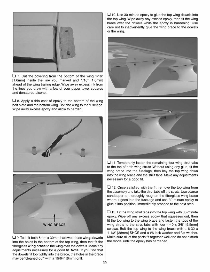
❏ 9. Test fi t both 6mm x 30mm hardwood top wing dowelsinto the holes in the bottom of the top wing, then test fi t the fi berglass wing brace to the wing over the dowels. Make any adjustments necessary for a good fi t. Note: If you fi nd that the dowels fi t too tightly into the brace, the holes in the brace may be “cleaned out” with a 15/64" [6mm] drill.
❏ 10. Use 30-minute epoxy to glue the top wing dowels into the top wing. Wipe away any excess epoxy, then fi t the wing brace over the dowels while the epoxy is hardening. Use care not to inadvertently glue the wing brace to the dowels or the wing.
❏ 11. Temporarily fasten the remaining four wing strut tabs to the top of both wing struts. Without using any glue, fi t the wing brace into the fuselage, then key the top wing down into the wing brace and the strut tabs. Make any adjustments necessary for a good fi t.
❏ 12. Once satisfi ed with the fi t, remove the top wing from the assembly and take the strut tabs off the struts. Use coarse sandpaper to thoroughly roughen the fi berglass wing brace where it goes into the fuselage and use 30-minute epoxy to glue it into position. Immediately proceed to the next step.
❏ 13. Fit the wing strut tabs into the top wing with 30-minute epoxy. Wipe off any excess epoxy that squeezes out, then fi t the top wing to the wing brace and fasten the tops of the wing struts to the strut tabs with four 4-40 x 3/8" [9.5mm] screws. Bolt the top wing to the wing brace with a 6-32 x 1-1/2" [38mm] SHCS and a #6 lock washer and fl at washer. Make sure all of the parts fi t together well and do not disturb the model until the epoxy has hardened.
26
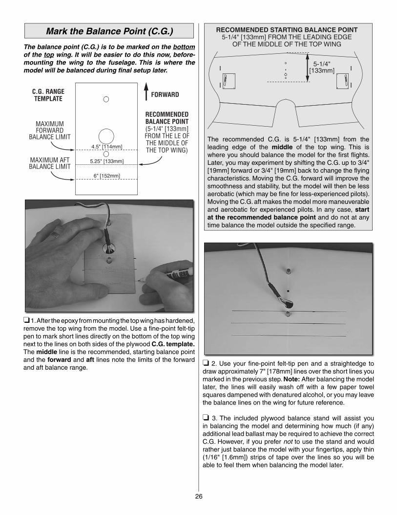
5-1/4"[133mm]
RECOMMENDED STARTING BALANCE POINT5-1/4" [133mm] FROM THE LEADING EDGE
OF THE MIDDLE OF THE TOP WING
The recommended C.G. is 5-1/4" [133mm] from the leading edge of the middle of the top wing. This is where you should balance the model for the fi rst fl ights. Later, you may experiment by shifting the C.G. up to 3/4" [19mm] forward or 3/4" [19mm] back to change the fl ying characteristics. Moving the C.G. forward will improve the smoothness and stability, but the model will then be less aerobatic (which may be fi ne for less-experienced pilots). Moving the C.G. aft makes the model more maneuverable and aerobatic for experienced pilots. In any case, start at the recommended balance point and do not at any time balance the model outside the specifi ed range.
❏ 2. Use your fi ne-point felt-tip pen and a straightedge to draw approximately 7" [178mm] lines over the short lines you marked in the previous step. Note: After balancing the model later, the lines will easily wash off with a few paper towel squares dampened with denatured alcohol, or you may leave the balance lines on the wing for future reference.
❏ 3. The included plywood balance stand will assist you in balancing the model and determining how much (if any) additional lead ballast may be required to achieve the correct C.G. However, if you prefer not to use the stand and would rather just balance the model with your fi ngertips, apply thin (1/16" [1.6mm]) strips of tape over the lines so you will be able to feel them when balancing the model later.
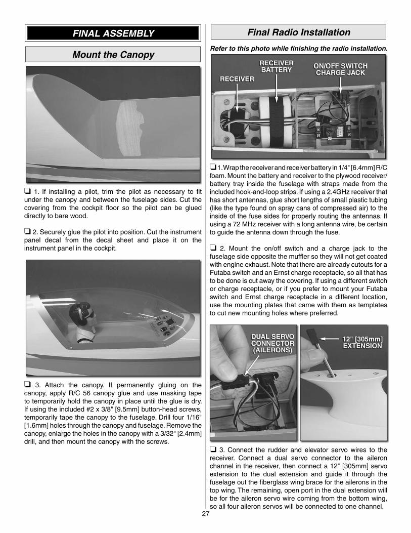
Mark the Balance Point (C.G.)
The balance point (C.G.) is to be marked on the bottomof the top wing. It will be easier to do this now, before-mounting the wing to the fuselage. This is where the model will be balanced during fi nal setup later.
MAXIMUMFORWARD
BALANCE LIMIT
MAXIMUM AFTBALANCE LIMIT
RECOMMENDEDBALANCE POINT(5-1/4" [133mm]FROM THE LE OFTHE MIDDLE OFTHE TOP WING)
FORWARDC.G. RANGETEMPLATE
4.5" [114mm]
5.25" [133mm]
6" [152mm]
❏ 1. After the epoxy from mounting the top wing has hardened, remove the top wing from the model. Use a fi ne-point felt-tip pen to mark short lines directly on the bottom of the top wing next to the lines on both sides of the plywood C.G. template.The middle line is the recommended, starting balance point and the forward and aft lines note the limits of the forward and aft balance range.
27
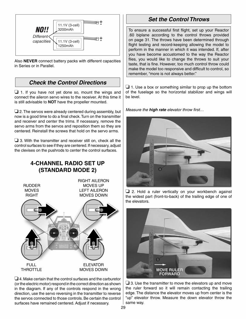
Final Radio Installation
Refer to this photo while fi nishing the radio installation.
❏ 1. Wrap the receiver and receiver battery in 1/4" [6.4mm] R/C foam. Mount the battery and receiver to the plywood receiver/battery tray inside the fuselage with straps made from the included hook-and-loop strips. If using a 2.4GHz receiver that has short antennas, glue short lengths of small plastic tubing (like the type found on spray cans of compressed air) to the inside of the fuse sides for properly routing the antennas. If using a 72 MHz receiver with a long antenna wire, be certain to guide the antenna down through the fuse.
❏ 2. Mount the on/off switch and a charge jack to the fuselage side opposite the muffl er so they will not get coated with engine exhaust. Note that there are already cutouts for a Futaba switch and an Ernst charge receptacle, so all that has to be done is cut away the covering. If using a different switch or charge receptacle, or if you prefer to mount your Futaba switch and Ernst charge receptacle in a different location, use the mounting plates that came with them as templates to cut new mounting holes where preferred.
❏ 3. Connect the rudder and elevator servo wires to the receiver. Connect a dual servo connector to the aileron channel in the receiver, then connect a 12" [305mm] servo extension to the dual extension and guide it through the fuselage out the fi berglass wing brace for the ailerons in the top wing. The remaining, open port in the dual extension will be for the aileron servo wire coming from the bottom wing, so all four aileron servos will be connected to one channel.
FINAL ASSEMBLY
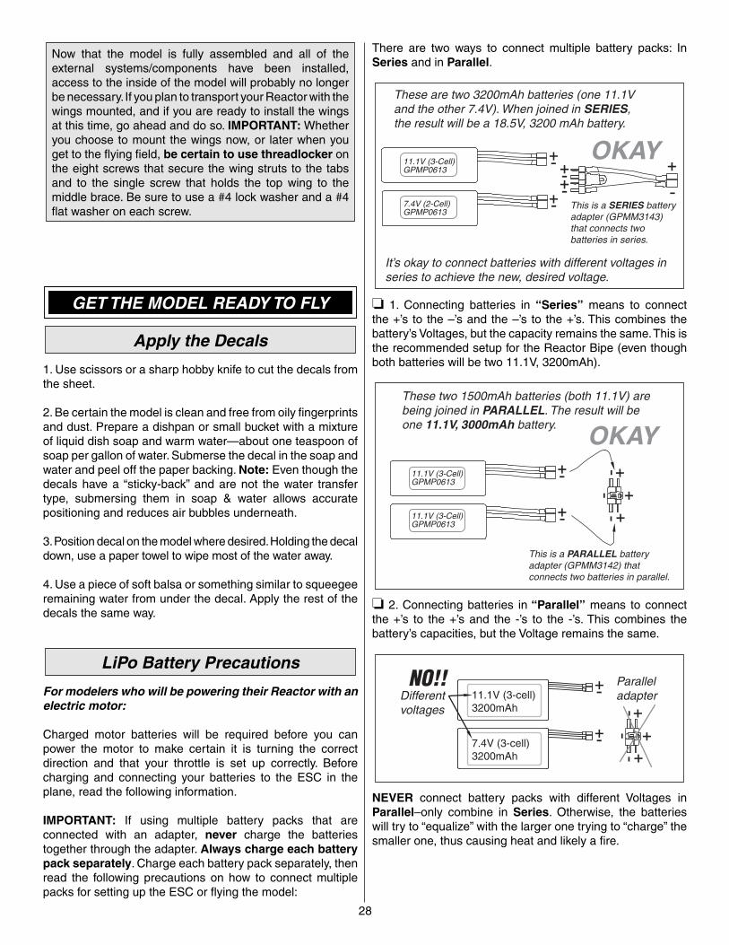
Mount the Canopy
❏ 1. If installing a pilot, trim the pilot as necessary to fi t under the canopy and between the fuselage sides. Cut the covering from the cockpit fl oor so the pilot can be glued directly to bare wood.
❏ 2. Securely glue the pilot into position. Cut the instrument panel decal from the decal sheet and place it on the instrument panel in the cockpit.
❏ 3. Attach the canopy. If permanently gluing on the canopy, apply R/C 56 canopy glue and use masking tape to temporarily hold the canopy in place until the glue is dry. If using the included #2 x 3/8" [9.5mm] button-head screws, temporarily tape the canopy to the fuselage. Drill four 1/16" [1.6mm] holes through the canopy and fuselage. Remove the canopy, enlarge the holes in the canopy with a 3/32" [2.4mm] drill, and then mount the canopy with the screws.
28
There are two ways to connect multiple battery packs: In Series and in Parallel.
These are two 3200mAh batteries (one 11.1Vand the other 7.4V). When joined in SERIES,the result will be a 18.5V, 3200 mAh battery.
It’s okay to connect batteries with different voltages inseries to achieve the new, desired voltage.
This is a SERIES batteryadapter (GPMM3143)that connects twobatteries in series.
11.1V (3-Cell)GPMP0613
OKAY
7.4V (2-Cell)GPMP0613
❏ 1. Connecting batteries in “Series” means to connect the +’s to the –’s and the –’s to the +’s. This combines the battery’s Voltages, but the capacity remains the same. This is the recommended setup for the Reactor Bipe (even though both batteries will be two 11.1V, 3200mAh).
These two 1500mAh batteries (both 11.1V) arebeing joined in PARALLEL. The result will beone 11.1V, 3000mAh battery.
This is a PARALLEL batteryadapter (GPMM3142) thatconnects two batteries in parallel.
11.1V (3-Cell)GPMP0613
OKAY
11.1V (3-Cell)GPMP0613
❏ 2. Connecting batteries in “Parallel” means to connect the +’s to the +’s and the -’s to the -’s. This combines the battery’s capacities, but the Voltage remains the same.
NO!!
NEVER connect battery packs with different Voltages in Parallel–only combine in Series. Otherwise, the batteries will try to “equalize” with the larger one trying to “charge” the smaller one, thus causing heat and likely a fi re.
Now that the model is fully assembled and all of the external systems/components have been installed, access to the inside of the model will probably no longer be necessary. If you plan to transport your Reactor with the wings mounted, and if you are ready to install the wings at this time, go ahead and do so. IMPORTANT: Whether you choose to mount the wings now, or later when you get to the fl ying fi eld, be certain to use threadlocker on the eight screws that secure the wing struts to the tabs and to the single screw that holds the top wing to the middle brace. Be sure to use a #4 lock washer and a #4 fl at washer on each screw.
GET THE MODEL READY TO FLY
Apply the Decals
1. Use scissors or a sharp hobby knife to cut the decals from the sheet.
2. Be certain the model is clean and free from oily fi ngerprints and dust. Prepare a dishpan or small bucket with a mixture of liquid dish soap and warm water—about one teaspoon of soap per gallon of water. Submerse the decal in the soap and water and peel off the paper backing. Note: Even though the decals have a “sticky-back” and are not the water transfer type, submersing them in soap & water allows accurate positioning and reduces air bubbles underneath.
3. Position decal on the model where desired. Holding the decal down, use a paper towel to wipe most of the water away.
4. Use a piece of soft balsa or something similar to squeegee remaining water from under the decal. Apply the rest of the decals the same way.
LiPo Battery Precautions
For modelers who will be powering their Reactor with an electric motor:
Charged motor batteries will be required before you can power the motor to make certain it is turning the correct direction and that your throttle is set up correctly. Before charging and connecting your batteries to the ESC in the plane, read the following information.
IMPORTANT: If using multiple battery packs that are connected with an adapter, never charge the batteries together through the adapter. Always charge each battery pack separately. Charge each battery pack separately, then read the following precautions on how to connect multiple packs for setting up the ESC or fl ying the model:
29
Set the Control Throws
To ensure a successful fi rst fl ight, set up your Reactor .60 biplane according to the control throws provided on page 31. The throws have been determined through fl ight testing and record-keeping allowing the model to perform in the manner in which it was intended. If, after you have become accustomed to the way the Reactor fl ies, you would like to change the throws to suit your taste, that is fi ne. However, too much control throw could make the model too responsive and diffi cult to control, so remember, “more is not always better.”
❏ 1. Use a box or something similar to prop up the bottom of the fuselage so the horizontal stabilizer and wings will be level.
Measure the high rate elevator throw fi rst…
❏ 2. Hold a ruler vertically on your workbench against the widest part (front-to-back) of the trailing edge of one of the elevators.
❏ 3. Use the transmitter to move the elevators up and move the ruler forward so it will remain contacting the trailing edge. The distance the elevator moves up from center is the “up” elevator throw. Measure the down elevator throw the same way.
NO!!
Also NEVER connect battery packs with different capacities in Series or in Parallel.
Check the Control Directions
❏ 1. If you have not yet done so, mount the wings and connect the aileron servo wires to the receiver. At this time it is still advisable to NOT have the propeller mounted.
❏ 2. The servos were already centered during assembly, but now is a good time to do a fi nal check. Turn on the transmitter and receiver and center the trims. If necessary, remove the servo arms from the servos and reposition them so they are centered. Reinstall the screws that hold on the servo arms.
❏ 3. With the transmitter and receiver still on, check all the control surfaces to see if they are centered. If necessary, adjust the clevises on the pushrods to center the control surfaces.
FULLTHROTTLE
RUDDERMOVESRIGHT
ELEVATORMOVES DOWN
RIGHT AILERONMOVES UP
LEFT AILERONMOVES DOWN
4-CHANNEL RADIO SET UP(STANDARD MODE 2)
❏ 4. Make certain that the control surfaces and the carburetor (or the electric motor) respond in the correct direction as shown in the diagram. If any of the controls respond in the wrong direction, use the servo reversing in the transmitter to reverse the servos connected to those controls. Be certain the control surfaces have remained centered. Adjust if necessary.
30
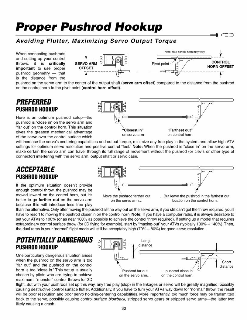
When connecting pushrods and setting up your control throws, it is critically important to use proper pushrod geometry — that is the distance from the pushrod on the servo arm to the center of the output shaft (servo arm offset) compared to the distance from the pushrod on the control horn to the pivot point (control horn offset).
Pivot point CONTROLHORN OFFSET
SERVO ARMOFFSET
Note: Your control horn may vary.
One particularly dangerous situation arises when the pushrod on the servo arm is too “far out” and the pushrod on the control horn is too “close in.” This setup is usually chosen by pilots who are trying to achieve maximum, “monster” control throws for 3D fl ight. But with your pushrods set up this way, any free play (slop) in the linkages or servo will be greatly magnifi ed, possibly causing destructive control surface fl utter. Additionally, if you have to turn your ATVs way down for “normal” throw, the result will be poor resolution and poor servo holding/centering capabilities. More importantly, too much force may be transmitted back to the servo, possibly causing control surface blowback, stripped servo gears or stripped servo arms—the latter two likely causing a crash.
POTENTIALLY DANGEROUSPUSHROD HOOKUP
Pushrod far outon the servo arm…
Longdistance
Shortdistance
…pushrod close inon the control horn.
Here is an optimum pushrod setup—the pushrod is “close in” on the servo arm and “far out” on the control horn. This situation gives the greatest mechanical advantage of the servo over the control surface which will increase the servo’s centering capabilities and output torque, minimize any free play in the system and allow high ATV settings for optimum servo resolution and positive control “feel.” Note: When the pushrod is “close in” on the servo arm, make certain the servo arm can travel through its full range of movement without the pushrod (or clevis or other type of connector) interfering with the servo arm, output shaft or servo case.
PREFERREDPUSHROD HOOKUP
“Closest in”on servo arm
“Farthest out”on control horn
If the optimum situation doesn’t provide enough control throw, the pushrod may be moved inward on the control horn, but it’s better to go farther out on the servo arm because this will introduce less free play than the alternative. Only after moving the pushrod all the way out on the servo arm, if you still can’t get the throw required, you’ll have to resort to moving the pushrod closer in on the control horn. Note: If you have a computer radio, it is always desirable to set your ATVs to 100% (or as near 100% as possible to achieve the control throw required). If setting up a model that requires extraordinary control surface throw (for 3D fl ying for example), start by “maxing-out” your ATVs (typically 130% – 140%). Then, the dual rates in your “normal” fl ight mode will still be acceptably high (70% – 80%) for good servo resolution.
ACCEPTABLEPUSHROD HOOKUP
Move the pushrod farther outon the servo arm…
…But leave the pushrod in the farthest outlocation on the control horn.
Proper Pushrod HookupAvoiding Flutter, Maximizing Servo Output Torque
31
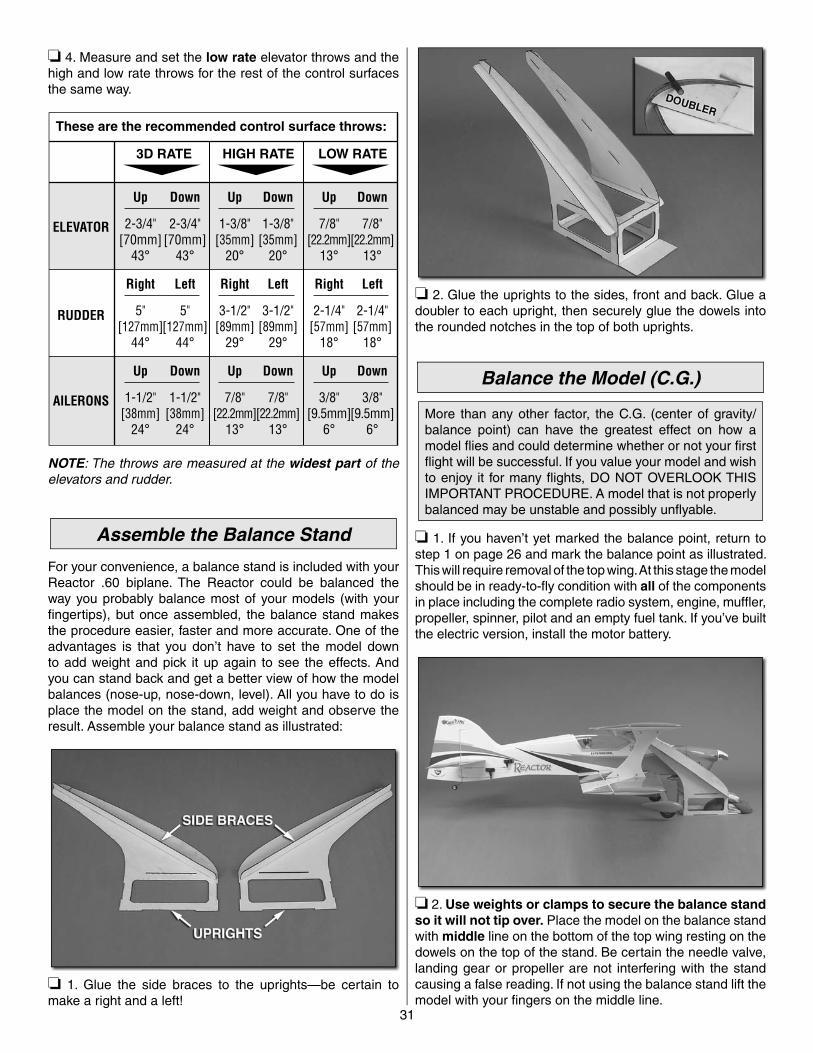
❏ 2. Glue the uprights to the sides, front and back. Glue a doubler to each upright, then securely glue the dowels into the rounded notches in the top of both uprights.
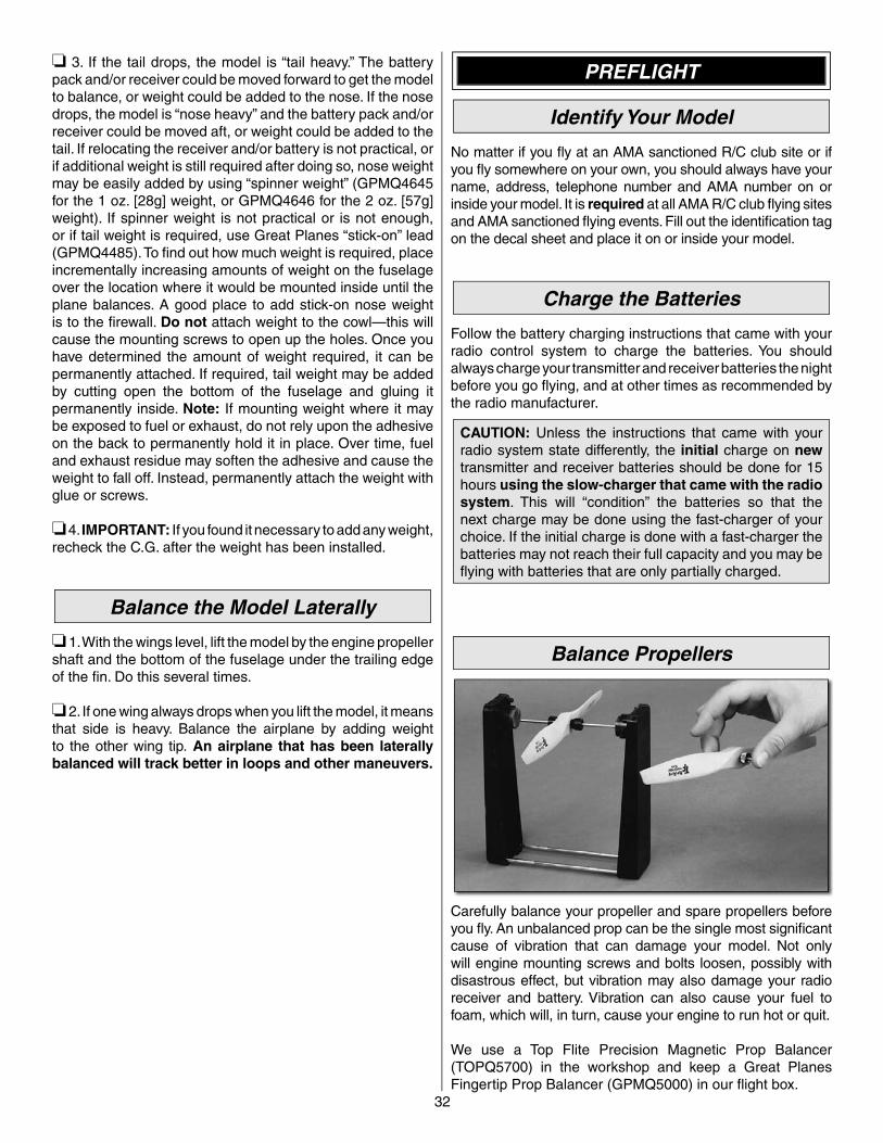
Balance the Model (C.G.)
More than any other factor, the C.G. (center of gravity/balance point) can have the greatest effect on how a model fl ies and could determine whether or not your fi rst fl ight will be successful. If you value your model and wish to enjoy it for many fl ights, DO NOT OVERLOOK THIS IMPORTANT PROCEDURE. A model that is not properly balanced may be unstable and possibly unfl yable.
❏ 1. If you haven’t yet marked the balance point, return to step 1 on page 26 and mark the balance point as illustrated. This will require removal of the top wing. At this stage the model should be in ready-to-fl y condition with all of the components in place including the complete radio system, engine, muffl er, propeller, spinner, pilot and an empty fuel tank. If you’ve built the electric version, install the motor battery.
❏ 2. Use weights or clamps to secure the balance stand so it will not tip over. Place the model on the balance stand with middle line on the bottom of the top wing resting on the dowels on the top of the stand. Be certain the needle valve, landing gear or propeller are not interfering with the stand causing a false reading. If not using the balance stand lift the model with your fi ngers on the middle line.
❏ 4. Measure and set the low rate elevator throws and the high and low rate throws for the rest of the control surfaces the same way.
These are the recommended control surface throws:
ELEVATOR
LOW RATE
RUDDER
AILERONS
7/8"[22.2mm]
13°
Up
7/8"[22.2mm]
13°
Down
2-1/4"[57mm]
18°
Right
2-1/4"[57mm]
18°
Left
3/8"[9.5mm]
6°
Up
3/8"[9.5mm]
6°
Down
3D RATE
2-3/4"[70mm]
43°
Up
2-3/4"[70mm]
43°
Down
5"[127mm]
44°
Right
5"[127mm]
44°
Left
1-1/2"[38mm]
24°
Up
1-1/2"[38mm]
24°
Down
HIGH RATE
1-3/8"[35mm]
20°
Up
1-3/8"[35mm]
20°
Down
3-1/2"[89mm]
29°
Right
3-1/2"[89mm]
29°
Left
7/8"[22.2mm]
13°
Up
7/8"[22.2mm]
13°
Down
NOTE: The throws are measured at the widest part of the elevators and rudder.
Assemble the Balance Stand
For your convenience, a balance stand is included with your Reactor .60 biplane. The Reactor could be balanced the way you probably balance most of your models (with your fi ngertips), but once assembled, the balance stand makes the procedure easier, faster and more accurate. One of the advantages is that you don’t have to set the model down to add weight and pick it up again to see the effects. And you can stand back and get a better view of how the model balances (nose-up, nose-down, level). All you have to do is place the model on the stand, add weight and observe the result. Assemble your balance stand as illustrated:
❏ 1. Glue the side braces to the uprights—be certain to make a right and a left!
32
PREFLIGHT
Identify Your Model
No matter if you fl y at an AMA sanctioned R/C club site or if you fl y somewhere on your own, you should always have your name, address, telephone number and AMA number on or inside your model. It is required at all AMA R/C club fl ying sites and AMA sanctioned fl ying events. Fill out the identifi cation tag on the decal sheet and place it on or inside your model.
Charge the Batteries
Follow the battery charging instructions that came with your radio control system to charge the batteries. You should always charge your transmitter and receiver batteries the night before you go fl ying, and at other times as recommended by the radio manufacturer.
CAUTION: Unless the instructions that came with your radio system state differently, the initial charge on new transmitter and receiver batteries should be done for 15 hours using the slow-charger that came with the radio system. This will “condition” the batteries so that the next charge may be done using the fast-charger of your choice. If the initial charge is done with a fast-charger the batteries may not reach their full capacity and you may be fl ying with batteries that are only partially charged.
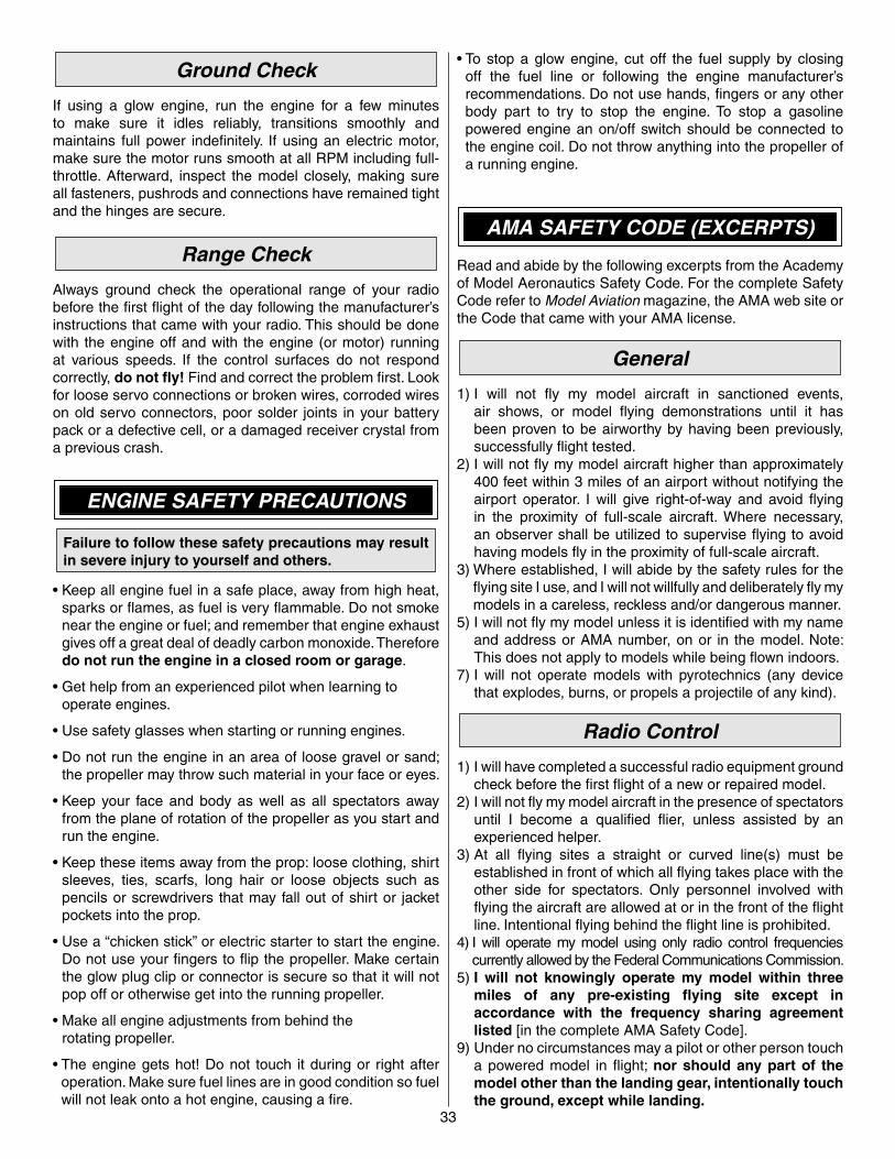
Balance Propellers
Carefully balance your propeller and spare propellers before you fl y. An unbalanced prop can be the single most signifi cant cause of vibration that can damage your model. Not only will engine mounting screws and bolts loosen, possibly with disastrous effect, but vibration may also damage your radio receiver and battery. Vibration can also cause your fuel to foam, which will, in turn, cause your engine to run hot or quit.
We use a Top Flite Precision Magnetic Prop Balancer (TOPQ5700) in the workshop and keep a Great Planes Fingertip Prop Balancer (GPMQ5000) in our fl ight box.
❏ 3. If the tail drops, the model is “tail heavy.” The battery pack and/or receiver could be moved forward to get the model to balance, or weight could be added to the nose. If the nose drops, the model is “nose heavy” and the battery pack and/or receiver could be moved aft, or weight could be added to the tail. If relocating the receiver and/or battery is not practical, or if additional weight is still required after doing so, nose weight may be easily added by using “spinner weight” (GPMQ4645 for the 1 oz. [28g] weight, or GPMQ4646 for the 2 oz. [57g] weight). If spinner weight is not practical or is not enough, or if tail weight is required, use Great Planes “stick-on” lead (GPMQ4485). To fi nd out how much weight is required, place incrementally increasing amounts of weight on the fuselage over the location where it would be mounted inside until the plane balances. A good place to add stick-on nose weight is to the fi rewall. Do not attach weight to the cowl—this will cause the mounting screws to open up the holes. Once you have determined the amount of weight required, it can be permanently attached. If required, tail weight may be added by cutting open the bottom of the fuselage and gluing it permanently inside. Note: If mounting weight where it may be exposed to fuel or exhaust, do not rely upon the adhesive on the back to permanently hold it in place. Over time, fuel and exhaust residue may soften the adhesive and cause the weight to fall off. Instead, permanently attach the weight with glue or screws.
❏ 4. IMPORTANT: If you found it necessary to add any weight, recheck the C.G. after the weight has been installed.
Balance the Model Laterally
❏ 1. With the wings level, lift the model by the engine propeller shaft and the bottom of the fuselage under the trailing edge of the fi n. Do this several times.
❏ 2. If one wing always drops when you lift the model, it means that side is heavy. Balance the airplane by adding weight to the other wing tip. An airplane that has been laterally balanced will track better in loops and other maneuvers.
33
• To stop a glow engine, cut off the fuel supply by closing off the fuel line or following the engine manufacturer’s recommendations. Do not use hands, fi ngers or any other body part to try to stop the engine. To stop a gasoline powered engine an on/off switch should be connected to the engine coil. Do not throw anything into the propeller of a running engine.
AMA SAFETY CODE (EXCERPTS)
Read and abide by the following excerpts from the Academy of Model Aeronautics Safety Code. For the complete Safety Code refer to Model Aviation magazine, the AMA web site or the Code that came with your AMA license.
General
1) I will not fl y my model aircraft in sanctioned events, air shows, or model fl ying demonstrations until it has been proven to be airworthy by having been previously, successfully fl ight tested.
2) I will not fl y my model aircraft higher than approximately 400 feet within 3 miles of an airport without notifying the airport operator. I will give right-of-way and avoid fl ying in the proximity of full-scale aircraft. Where necessary, an observer shall be utilized to supervise fl ying to avoid having models fl y in the proximity of full-scale aircraft.
3) Where established, I will abide by the safety rules for the fl ying site I use, and I will not willfully and deliberately fl y my models in a careless, reckless and/or dangerous manner.
5) I will not fl y my model unless it is identifi ed with my name and address or AMA number, on or in the model. Note: This does not apply to models while being fl own indoors.
7) I will not operate models with pyrotechnics (any device that explodes, burns, or propels a projectile of any kind).
Radio Control
1) I will have completed a successful radio equipment ground check before the fi rst fl ight of a new or repaired model.
2) I will not fl y my model aircraft in the presence of spectators until I become a qualifi ed fl ier, unless assisted by an experienced helper.
3) At all fl ying sites a straight or curved line(s) must be established in front of which all fl ying takes place with the other side for spectators. Only personnel involved with fl ying the aircraft are allowed at or in the front of the fl ight line. Intentional fl ying behind the fl ight line is prohibited.
4) I will operate my model using only radio control frequencies currently allowed by the Federal Communications Commission.
5) I will not knowingly operate my model within three miles of any pre-existing fl ying site except in accordance with the frequency sharing agreement listed [in the complete AMA Safety Code].
9) Under no circumstances may a pilot or other person touch a powered model in fl ight; nor should any part of the model other than the landing gear, intentionally touch the ground, except while landing.
Ground Check
If using a glow engine, run the engine for a few minutes to make sure it idles reliably, transitions smoothly and maintains full power indefi nitely. If using an electric motor, make sure the motor runs smooth at all RPM including full-throttle. Afterward, inspect the model closely, making sure all fasteners, pushrods and connections have remained tight and the hinges are secure.
Range Check
Always ground check the operational range of your radio before the fi rst fl ight of the day following the manufacturer’s instructions that came with your radio. This should be done with the engine off and with the engine (or motor) running at various speeds. If the control surfaces do not respond correctly, do not fl y! Find and correct the problem fi rst. Look for loose servo connections or broken wires, corroded wires on old servo connectors, poor solder joints in your battery pack or a defective cell, or a damaged receiver crystal from a previous crash.
ENGINE SAFETY PRECAUTIONS
Failure to follow these safety precautions may result in severe injury to yourself and others.
• Keep all engine fuel in a safe place, away from high heat, sparks or fl ames, as fuel is very fl ammable. Do not smoke near the engine or fuel; and remember that engine exhaust gives off a great deal of deadly carbon monoxide. Therefore do not run the engine in a closed room or garage.
• Get help from an experienced pilot when learning tooperate engines.
• Use safety glasses when starting or running engines.
• Do not run the engine in an area of loose gravel or sand; the propeller may throw such material in your face or eyes.
• Keep your face and body as well as all spectators away from the plane of rotation of the propeller as you start and run the engine.
• Keep these items away from the prop: loose clothing, shirt sleeves, ties, scarfs, long hair or loose objects such as pencils or screwdrivers that may fall out of shirt or jacket pockets into the prop.
• Use a “chicken stick” or electric starter to start the engine. Do not use your fi ngers to fl ip the propeller. Make certain the glow plug clip or connector is secure so that it will not pop off or otherwise get into the running propeller.
• Make all engine adjustments from behind therotating propeller.
• The engine gets hot! Do not touch it during or right after operation. Make sure fuel lines are in good condition so fuel will not leak onto a hot engine, causing a fi re.
34
FLYING
The Reactor .60 biplane is a great-fl ying model that fl ies smoothly and predictably. The Reactor is, however, a very “neutral” fl ying model that does not possess the same “self-correcting” tendencies that a trainer model possesses and should be fl own only by pilots who have at least been checked out on a 4-channel low-wing, sport plane.
CAUTION (THIS APPLIES TO ALL R/C AIRPLANES): If, while fl ying, you notice an alarming or unusual sound such as a low-pitched “buzz,” this may indicate control surface fl utter. Flutter occurs when a control surface (such as an aileron or elevator) or a fl ying surface (such as a wing or stab) rapidly vibrates up and down (thus causing the noise). In extreme cases, if not detected immediately, fl utter can actually cause the control surface to detach or the fl ying surface to fail, thus causing loss of control followed by an impending crash. The best thing to do when fl utter is detected is to slow the model immediately by reducing power, then land as soon as safely possible. Identify which surface fl uttered (so the problem may be resolved) by checking all the servo grommets for deterioration or signs of vibration. Make certain all pushrod linkages are secure and free of play. If it fl uttered once, under similar circumstances it will probably fl utter again unless the problem is fi xed. Some things which can cause fl utter are; Excessive hinge gap; Not mounting control horns solidly; Poor fi t of clevis pin in horn; Side-play of wire pushrods caused by large bends; Excessive free play in servo gears; Insecure servo mounting; and one of the most prevalent causes of fl utter; Flying an over-powered model at excessive speeds.
Takeoff
If this is your fi rst biplane or 3D model, for reassurance and to keep an eye on other traffi c, it is a good idea to have an assistant on the fl ight line with you. Tell him to remind you to throttle back once the plane gets to a comfortable altitude. While full throttle may be desirable for takeoff, most models fl y more smoothly at reduced speeds.
The Reactor .61 Bipe is an agile, lightweight model, so there won’t be much of a takeoff roll. But it does ground-handle extremely well—both on grass and on pavement—so takeoff should be pretty easy. Simply point the model into the wind and smoothly advance the throttle. If you are taking off from grass—especially rough grass—initially hold some “up” elevator to keep the tail on the ground until the model builds up speed (which will be in just a second or two). Stay “on top” of the rudder to keep the model pointing down the runway. Allow the model to “break ground” and establish a gentle climb. Be ready on the controls to get the model tracking straight. Then make your fi rst turn away from the fl ight line. If you are nervous or fi nd yourself overcorrecting, remember to throttle back.
CHECK LIST
During the last few moments of preparation your mind may be elsewhere anticipating the excitement of the fi rst fl ight. Because of this, you may be more likely to overlook certain checks and procedures that should be performed before the model is fl own. To help avoid this, a check list is provided to make sure these important areas are not overlooked. Many are covered in the instruction manual, so where appropriate, refer to the manual for complete instructions. Be sure to check the items off as they are completed.
❏ 1. Be certain you have checked and set the C.G. according to the measurements provided.
❏ 2. Be certain the battery and receiver are securely mounted. Simply stuffi ng them into place with foam rubber is not suffi cient.
❏ 3. If using a radio on 72 MHz, extend the receiver antenna down through the fuselage. If using a radio on 2.4GHz, make sure the antennas(s) are-mounted and oriented as suggested in the instructions that came with the radio system.
❏ 4. Make sure the model has been balanced laterally as explained in the instructions.
❏ 5. Use threadlocking compound to secure critical fasteners such as the screws that hold the wheel collars to the axles, screws in any screw-lock pushrod connectors and the screws that hold the wing struts to the mounting tabs on the wings.
❏ 6. Add a drop of oil to the axles so the wheels will turn freely.❏ 7. Make sure all hinges are securely glued in place by
tugging on the control surfaces.❏ 8. Reinforce holes for wood screws with thin CA
where appropriate (servo mounting screws, aileron control horns).
❏ 9. Confi rm that all controls operate in the correct direction and the throws are set up according to the manual.
❏ 10. Make sure there are silicone retainers on all the clevises and that all servo arms are secured to the servos with the screws included with your radio.
❏ 11. Secure connections between servo wires and Y-connectors or servo extensions, and the connection between your battery pack and the on/off switch with vinyl tape, heat shrink tubing or special clips suitable for that purpose.
❏ 12. Make sure the fuel lines are connected and are not kinked.
❏ 13. Balance your propeller (and spare propellers).❏ 14. Tighten the propeller nut and spinner.❏ 15. Place your name, address, AMA number and telephone
number on or inside your model.❏ 16. Make sure your receiver battery pack is fully charged.❏ 17. Range check your radio when you get to the fl ying fi eld.
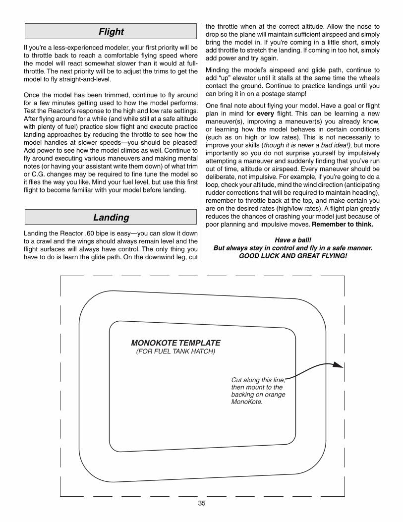
35
the throttle when at the correct altitude. Allow the nose to drop so the plane will maintain suffi cient airspeed and simply bring the model in. If you’re coming in a little short, simply add throttle to stretch the landing. If coming in too hot, simply add power and try again.
Minding the model’s airspeed and glide path, continue to add “up” elevator until it stalls at the same time the wheels contact the ground. Continue to practice landings until you can bring it in on a postage stamp!
One fi nal note about fl ying your model. Have a goal or fl ight plan in mind for every fl ight. This can be learning a new maneuver(s), improving a maneuver(s) you already know, or learning how the model behaves in certain conditions (such as on high or low rates). This is not necessarily to improve your skills (though it is never a bad idea!), but more importantly so you do not surprise yourself by impulsively attempting a maneuver and suddenly fi nding that you’ve run out of time, altitude or airspeed. Every maneuver should be deliberate, not impulsive. For example, if you’re going to do a loop, check your altitude, mind the wind direction (anticipating rudder corrections that will be required to maintain heading), remember to throttle back at the top, and make certain you are on the desired rates (high/low rates). A fl ight plan greatly reduces the chances of crashing your model just because of poor planning and impulsive moves. Remember to think.
Have a ball!But always stay in control and fl y in a safe manner.
GOOD LUCK AND GREAT FLYING!
Flight
If you’re a less-experienced modeler, your fi rst priority will be to throttle back to reach a comfortable fl ying speed where the model will react somewhat slower than it would at full-throttle. The next priority will be to adjust the trims to get the model to fl y straight-and-level.
Once the model has been trimmed, continue to fl y around for a few minutes getting used to how the model performs. Test the Reactor’s response to the high and low rate settings. After fl ying around for a while (and while still at a safe altitude with plenty of fuel) practice slow fl ight and execute practice landing approaches by reducing the throttle to see how the model handles at slower speeds—you should be pleased! Add power to see how the model climbs as well. Continue to fl y around executing various maneuvers and making mental notes (or having your assistant write them down) of what trim or C.G. changes may be required to fi ne tune the model so it fl ies the way you like. Mind your fuel level, but use this fi rst fl ight to become familiar with your model before landing.
Landing
Landing the Reactor .60 bipe is easy—you can slow it down to a crawl and the wings should always remain level and the fl ight surfaces will always have control. The only thing you have to do is learn the glide path. On the downwind leg, cut
Cut along this line, then mount to the backing on orangeMonoKote.
MONOKOTE TEMPLATE(FOR FUEL TANK HATCH)