Embed Size (px)
Citation preview

WARRANTYGreat Planes® Model Manufacturing Co. guarantees this kit to be free from defects in both material and workmanship at the date of purchase.This warranty does not cover any component parts damaged by use or modification. In no case shall Great Planes’ liability exceed theoriginal cost of the purchased kit. Further, Great Planes reserves the right to change or modify this warranty without notice.
In that Great Planes has no control over the final assembly or material used for final assembly, no liability shall be assumed nor accepted forany damage resulting from the use by the user of the final user-assembled product. By the act of using the user-assembled product, the useraccepts all resulting liability.
If the buyer is not prepared to accept the liability associated with the use of this product, the buyer is advised to return this kitimmediately in new and unused condition to the place of purchase.
To make a warranty claim send the defective part or item to Hobby Services at the address below:
Hobby Services3002 N. Apollo Dr., Suite 1
Champaign, IL 61822USA
Include a letter stating your name, return shipping address, as much contact information as possible (daytime telephone number, fax number,e-mail address), a detailed description of the problem and a photocopy of the purchase receipt. Upon receipt of the package the problem willbe evaluated as quickly as possible.
READ THROUGH THIS MANUAL BEFORE STARTINGCONSTRUCTION. IT CONTAINS IMPORTANT INSTRUCTIONSAND WARNINGS CONCERNING THE ASSEMBLY ANDUSE OF THIS MODEL.
GPMZ0186 for GPMA1165 V1.2Entire Contents © Copyright 2006
Champaign, Illinois(217) 398-8970, Ext 5
INSTRUCTION MANUAL
Wingspan: 43 in [1090 mm]Wing Area: 237 sq in [15.3 dm2]Weight: 26 – 32 oz [735 – 905 g]Wing Loading: 15.8 – 19.4 oz/sq ft [48 – 59 g/dm2]Length: 31 in [785 mm]Radio: 4-channel with four micro servos and micro receiver

2
INTRODUCTION ...............................................................2AMA...................................................................................2SAFETY PRECAUTIONS..................................................3DECISIONS YOU MUST MAKE ........................................3
Radio Equipment.........................................................3Charger .......................................................................3
ADDITIONAL ITEMS REQUIRED.....................................4Required Hardware & Building Supplies .....................4Optional Supplies & Tools ...........................................4
IMPORTANT BUILDING NOTES ......................................4ORDERING REPLACEMENT PARTS ..............................5METRIC CONVERSIONS .................................................5COMMON ABBREVIATIONS............................................5KIT INSPECTION ..............................................................6KIT CONTENTS ................................................................6BEFORE YOU BEGIN .......................................................7ASSEMBLE THE WING ....................................................7ASSEMBLE THE TAIL SECTION......................................9
Install the Stabilizer .....................................................9Build the Pushrods ....................................................11Finish the Tail Section ...............................................11
ASSEMBLE THE FUSELAGE.........................................13Install the Radio Tray & Wing Joiner Tube.................13Assemble the Landing Gear......................................14Install the Landing Gear ............................................15Install the Radio System & Battery ...........................16
FINISH THE MODEL .......................................................17Attach the Wing Panels .............................................17Attach the Canopy & Cowl ........................................18Attach the Propeller & Spinner..................................19Apply the Decals .......................................................19
GET THE MODEL READY TO FLY .................................19Check the Control Directions ....................................19Set the Control Throws..............................................19Balance the Model (C.G.)..........................................20Balance the Model Laterally......................................20
PREFLIGHT.....................................................................20Identify Your Model ....................................................20Charge the Batteries .................................................21Balance the Propellers ..............................................21Ground Check ...........................................................21Range Check.............................................................21
MOTOR SAFETY PRECAUTIONS .................................21AMA SAFETY CODE (excerpts)....................................22
General......................................................................22Radio Control ............................................................22
CHECK LIST ...................................................................22FLYING ............................................................................23
Speed Control Set-Up ...............................................23Takeoff .......................................................................23Flight..........................................................................23Landing......................................................................23
The Great Planes Lancair ES EP ARF is a quick buildingscale park flyer that has everything you need except radioand servos to get you into the air in about 4 to 6 hours. A4-channel radio, with four micro servos and a micro receiver,provides aileron control as well as a steerable nose gear.Fiberglass fuselage, wheel pants, cowl, and wing tipsrecreate the unique contours of the Lancair ES as well aseasing the assembly.
Flying the Lancair ES EP ARF is extremely smooth andpredictable. Takeoffs are scale-like with graceful flaring of thenose as the model generates air speed. Landings allow a softtouch down on the main wheels first, with the plane slowlysettling back down on the nose wheel as it slows to taxi speeds.Even with a short 43 inch [1090 mm] wingspan, the Lancair ESEP ARF demonstrates the steady flight characteristics of largermodels and will surely be an attention-getter at the flying field.
For the latest technical updates or manual corrections to theLancair ES EP ARF visit the Great Planes web site atwww.greatplanes.com. Open the “Airplanes” link, thenselect the Lancair ES EP ARF. If there is new technicalinformation or changes to this model a “tech notice” box willappear in the upper left corner of the page.
We urge you to join the AMA (Academy of ModelAeronautics) and a local R/C club.The AMA is the governingbody of model aviation and membership is required to fly atAMA clubs.Though joining the AMA provides many benefits,one of the primary reasons to join is liability protection.Coverage is not limited to flying at contests or on the clubfield. It even applies to flying at public demonstrations andair shows. Failure to comply with the Safety Code (excerptsprinted in the back of the manual) may endanger insurancecoverage. Additionally, training programs and instructors areavailable at AMA club sites to help you get started the rightway. There are over 2,500 AMA chartered clubs across thecountry. Contact the AMA at the address or toll-free phonenumber below.
IMPORTANT!!! Two of the most important things you can doto preserve the radio controlled aircraft hobby are to avoidflying near full-scale aircraft and avoid flying near or overgroups of people.
Academy of Model Aeronautics5151 East Memorial Drive
Muncie, IN 47302Tele: (800) 435-9262Fax (765) 741-0057
Or via the Internet at:http://www.modelaircraft.org
AMA
INTRODUCTIONTABLE OF CONTENTS

1. Your Lancair ES EP ARF should not be considered a toy,but rather a sophisticated, working model that functions verymuch like a full-size airplane. Because of its performancecapabilities, the Lancair, if not assembled and operatedcorrectly, could possibly cause injury to yourself orspectators and damage to property.
2. You must assemble the model according to theinstructions. Do not alter or modify the model, as doing somay result in an unsafe or unflyable model. In a few casesthe instructions may differ slightly from the photos. In thoseinstances the written instructions should be consideredas correct.
3. You must take time to build straight, true and strong.
4. You must use an R/C radio system that is in first-classcondition and correctly sized components (servos, wheels,etc.) throughout the building process.
5. You must correctly install all R/C and other components sothat the model operates correctly on the ground and in the air.
6. You must check the operation of the model before everyflight to insure that all equipment is operating and that themodel has remained structurally sound. Be sure to checkclevises or other connectors often and replace them if theyshow any signs of wear or fatigue.
7. If you are not an experienced pilot or have not flown thistype of model before, we recommend that you get theassistance of an experienced pilot in your R/C club for yourfirst flights. If you’re not a member of a club, your local hobbyshop has information about clubs in your area whosemembership includes experienced pilots.
8. WARNING: The fuselage, cowl, wheel pants and wing tipsincluded in this kit are made of fiberglass, the fibers of whichmay cause eye, skin and respiratory tract irritation. Neverblow into a part (wheel pant, cowl) to remove fiberglass dust,as the dust will blow back into your eyes. Always wear safetygoggles, a particle mask and rubber gloves when grinding,drilling and sanding fiberglass parts. Vacuum the parts andthe work area thoroughly after working with fiberglass parts.
Remember: Take your time and follow the instructions toend up with a well-built model that is straight and true.
A 4-channel radio system with a micro receiver and fourmicro servos are the minimum requirements for the LancairEP ES ARF. The radio components can be purchased asseparate items or can be purchased as a package system.If you already have a Futaba® or Futaba-compatibletransmitter you plan to use with this model, part numbers forthe servos and receiver are provided below:
❏ (4) Futaba S3103 Servo Micro Mini (FUTM0037)❏ Futaba R114F 4-channel FM micro receiver w/o crystal
(low band – FUTL0442, high band – FUTL0443)❏ Futaba FM single conversion receiver crystal for R114F
(low band – FUTL62**, high band – FUTL63**)
If you plan to purchase a complete radio system, the Futaba4YF micro system is packaged with the Futaba R114F and twoS3108 micro servos. You will need to purchase an additionaltwo micro servos. The order numbers are provided.
❏ Futaba 4YF 4-Channel Micro FM/2 S3108 Servos (FUTJ37**)❏ (2) Futaba S3108 Servo Micro 7.6 g (FUTM0042)Since the Lancair ES EP ARF uses dual aileron servos, aY-harness will be required to connect the servos together aswell as one 9" [230 mm] servo extension. The order numbersare provided below:
❏ Futaba 6" Dual Servo Extension J (FUTM4130)❏ Futaba 9" Servo Extension J (FUTM3910)
The included battery is a 9.6V 1800mAh NiMH pack. A NiMHcompatible charger is required. An economical choice is theGreat Planes ElectriFly™ 400 DC charger. A Deans male ultraplug will also be necessary (soldering is required):
❏ Great Planes ElectriFly Peak 400 DC 1-10C PeakCharger (GPMM3001)
❏ Deans 2-Pin Ultra Plug (WSDM3001)
For a more advanced computerized charger, we recommendthe Great Planes Triton™ charger. Charge leads are notincluded with this model charger, so order numbers for thecorrect connector type, wire leads, and banana plugs arelisted below (soldering is required):
❏ Great Planes ElectriFly Triton™ DC Competition PeakCharger (GPMM3150)
❏ Deans Male Ultra Pigtail (WSDM2013)❏ Hobbico® Banana Plugs (6) (HCAP0310)
Charger
Radio Equipment
DECISIONS YOU MUST MAKE
We, as the kit manufacturer, provide you with a top quality,thoroughly tested kit and instructions, but ultimately thequality and flyability of your finished model depends onhow you build it; therefore, we cannot in any wayguarantee the performance of your completed model, andno representations are expressed or implied as to theperformance or safety of your completed model.
PROTECT YOUR MODEL, YOURSELF& OTHERS...FOLLOW THESE
IMPORTANT SAFETY PRECAUTIONS
3
This is the list of hardware and accessories required to finishthe Lancair ES EP ARF. Order numbers are providedin parentheses.
❏ #1 Hobby knife (HCAR0105)❏ #11 Blades (5-pack, HCAR0211)❏ Drill bits: 1/16" [1.6 mm], 5/64" [2 mm] ❏ 1/2 oz. [15 g] Thin Pro™ CA (GPMR6001)❏ 1/2 oz. [15 g] Medium Pro CA+ (GPMR6007)❏ 220-grit Sandpaper (GPMR6185)❏ Denatured alcohol (for epoxy clean up)❏ Pro™ 30-minute epoxy (GPMR6047)❏ Great Planes Metric Ball Wrench 1.5 mm (GPMR8010)
Here is a list of optional tools that will help you build theLancair ES EP ARF.
❏ 21st Century® sealing iron (COVR2700) ❏ 21st Century iron cover (COVR2702)❏ Hobbico® 60 watt soldering iron (HCAR0776)❏ Hayes Large Clamp 4" (HAYR1106)❏ Great Planes Precision Z-bend Pliers (GPMR8025)❏ 4 oz. [113 g] Aerosol CA activator (GPMR634)❏ CA applicator tips (HCAR3780)❏ CA debonder (GPMR6039)❏ Epoxy brushes (6, GPMR8060)❏ Mixing sticks (50, GPMR8055)❏ Mixing cups (GPMR8056)❏ Builder’s Triangle Set (HCAR0480)❏ 36" Metal ruler (HCAR0475)❏ Pliers with wire cutter (HCAR0630)❏ Hobbico Duster™ can of compressed air (HCAR5500)❏ Panel Line Pen (TOPQ2510)❏ Rotary tool such as Dremel®
❏ Hobby Heat™ Micro Torch II (HCAR0755)❏ CG Machine™ (GPMR2400)❏ Precision Magnetic Prop Balancer™ (TOPQ5700)❏ AccuThrow™ Deflection Gauge (GPMR2405) ❏ Top Flite® MonoKote® heat gun (TOPR2000)
• There are two types of screws used in this kit:
• Self-tapping (sheet metal) screws are designated by anumber and a length and are referred to as self-tappingscrews. For example 2.6 x 8 mm [7/64" x 5/16"].
This is a metric 2.6 mm diameter screw that is 8 mm long.
• Machine screws are designated by a number and alength and are referred to as machine screws. For example3 x 12 mm [1/8" x 7/16"].
This is a metric 3 x 12 mm machine screw that is3 mm in diameter and is 12 mm long.
Note: For accuracy, metric screws will be written with theactual metric dimensions first followed by the SAEequivalent in brackets. All other dimensions provided in thebuilding instructions will be written in English units firstfollowed by the metric equivalent in brackets.
• When you see the term test fit in the instructions, itmeans that you should first position the part on theassembly without using any glue, then slightly modify orcustom fit the part as necessary for the best fit.
• Whenever the term glue is written you should rely uponyour experience to decide what type of glue to use. When aspecific type of adhesive works best for that step, theinstructions will make a recommendation.
• Whenever just epoxy is specified, you may use either30-minute (or 45-minute) epoxy or 6-minute epoxy. When30-minute epoxy is specified, it is highly recommended thatyou use only 30-minute (or 45-minute) epoxy, because youwill need the working time and/or the additional strength.
• Photos and sketches are placed before the step theyrefer to. Frequently you can study photos in following stepsto get another view of the same parts.
• The stabilizer and wing incidences and motor thrust angleshave been factory-built into this model. However, sometechnically-minded modelers may wish to check thesemeasurements anyway. To view this information visit the website at www.greatplanes.com and click on “Technical Data.”Due to manufacturing tolerances which will have little or noeffect on the way your model will fly, please expect slightdeviations between your model and the published values.
IMPORTANT BUILDING NOTES
Optional Supplies & Tools
Required Hardware & Building Supplies
ADDITIONAL ITEMS REQUIRED
4

Replacement parts for the Great Planes Lancair ES EP ARF areavailable using the order numbers in the Replacement PartsList that follows. The fastest, most economical service can beprovided by your hobby dealer or mail-order company.
To locate a hobby dealer, visit the Hobbico web site atwww.hobbico.com. Choose “Where to Buy” at the bottom ofthe menu on the left side of the page. Follow the instructionsprovided on the page to locate a U.S., Canadian or Internationaldealer. If a hobby shop is not available, replacement parts may alsobe ordered from Tower Hobbies® at www.towerhobbies.com,or by calling toll free (800) 637-6050.
Parts may also be ordered directly from Hobby Services bycalling (217) 398-0007, or via facsimile at (217) 398-7721,but full retail prices and shipping and handling charges willapply. Illinois and Nevada residents will also be chargedsales tax. If ordering via fax, include a Visa® or MasterCard®
number and expiration date for payment.
Mail parts orders and payments by personal check to:
Hobby Services3002 N. Apollo Drive, Suite 1
Champaign, IL 61822
Be certain to specify the order number exactly as listed inthe Replacement Parts List. Payment by credit card orpersonal check only; no C.O.D.
If additional assistance is required for any reason contact ProductSupport by e-mail at [email protected], or bytelephone at (217) 398-8970.
Replacement Parts List
Order Number Description How to PurchaseMissing pieces Contact Product SupportInstruction manual Contact Product SupportFull-size plans Not available
GPMA2890 Wing Kit Contact Hobby SupplierGPMA2891 Fuse Kit Contact Hobby SupplierGPMA2892 Tail Set Contact Hobby SupplierGPMA2893 Cowl Contact Hobby SupplierGPMA2894 Canopy Contact Hobby SupplierGPMA2895 Landing Gear Contact Hobby SupplierGPMA2896 Wheel Pants Contact Hobby SupplierGPMA2897 Spinner Contact Hobby SupplierGPMG0325 Motor Contact Hobby SupplierGPMG0225 Gearbox Contact Hobby Supplier
1" = 25.4 mm (conversion factor)
Fuse = FuselageStab = Horizontal Stabilizer
Fin = Vertical FinLE = Leading EdgeTE = Trailing EdgeLG = Landing GearPly = Plywood
" = Inchesmm = Millimeters
SHCS = Socket Head Cap Screw
COMMON ABBREVIATIONS
METRIC CONVERSIONSORDERING REPLACEMENT PARTS
5
1/64" = .4 mm1/32" = .8 mm1/16" = 1.6 mm3/32" = 2.4 mm1/8" = 3.2 mm
5/32" = 4.0 mm3/16" = 4.8 mm1/4" = 6.4 mm3/8" = 9.5 mm1/2" = 12.7 mm5/8" = 15.9 mm
3/4" = 19.0 mm1" = 25.4 mm2" = 50.8 mm3" = 76.2 mm6" = 152.4 mm
12" = 304.8 mm18" = 457.2 mm21" = 533.4 mm24" = 609.6 mm30" = 762.0 mm36" = 914.4 mm

6
Before starting to build, take an inventory of this kit to make sure it is complete, and inspect the parts to make sure theyare of acceptable quality. If any parts are missing or are not of acceptable quality, or if you need assistance with assembly,contact Product Support. When reporting defective or missing parts, use the part names exactly as they are written inthe Kit Contents list.
Great Planes Product Support3002 N. Apollo Drive, Suite 1
Champaign, IL 61822Telephone: (217) 398-8970, ext. 5
Fax: (217) 398-7721E-mail: [email protected]
KIT INSPECTION
Hook & Loop Material(3) Nose Wire Brackets3 x 20 mm [1/8" x 1/8"] Machine Screw3 mm [1/8"] Wheel Collar2-56 x 1/8" [25 mm] Threaded Rod3/32" [2.4 mm] Wheel Collars(2) Anti-Rotation Pins(14) 2.6 x 8 mm [7/64" x 5/16"] Self-Tapping Screws(4) 2.6 x 10 mm [7/64" x 3/8"] Self-Tapping Screws(5) Screw-Lock Pushrod Connectors
(2) 2.6 x 8mm [7/64" x 5/16"] SpinnerScrews(3) 4-40 x 1/4" [6 mm] Socket Head CapScrews(2) Landing Gear Straps(4 pcs) Heat-Shrink Tubing(4) Main Wheel Retainers(2) Nose Wheel Retainers(3) 8-7/8" [225 mm] Pushrod Wires(2) 1/4" x 1/4" x 12" [6 x 6 x 305 mm]Balsa Sticks1800mAh 9.6V NiMH Battery pack
Electronic Speed Control (ESC)(4) Control Horns w/Backplates(2) 2-7/8" [73 mm] Aileron Pushrods1/4" x 9-3/4" [6 x 247 mm] Carbon WingJoiner TubeRadio Tray BraceRadio TrayVertical Radio Tray Support(2) Main Wheel Pant StrapsNose Wheel Pant Strap
Kit Contents (not photographed)
KIT CONTENTS
1
43
9
10
13
1414
11
10
2
7
Kit Contents
1. Vertical Stabilizer & Rudder2. Horizontal Stabilizer & Elevators3. Fuselage4. Canopy5. Nose Gear6. Nose Wheel7. Main Landing Gear (L&R)8. Main Wheels (2)9. Wheels Pants (3)10. Wing Panels w/Ailerons (L&R)11. Cowl12. Spinner13. 9x6 Propeller14. Wing Tips (L&R)
5
6 8
12

❏ 1. Locate the aileron servo bays by holding the wingpanels up to a light source or gently pressing against thecovering looking for the edges of these cutouts. Use a sharphobby knife to trim the covering away from the servo bays.
❏ 2. Trim the covering away from the slots in the servobay covers.
❏ 3. Cut off three arms from two four-arm servo hornsleaving one of the long arms intact as shown. Attach theservo horns at a right angle to the servos using the screwsincluded with the servos. Enlarge the outer holes of theservo horns with a 1/16" [1.6 mm] drill bit.
❏ 4. We recommend gluing the aileron servos to the servobay covers with medium CA glue. Insert the servos throughthe underside of the covers and apply epoxy around eachservo mounting tab to secure them. If you do not wish toglue the servos in place, you can insert the servos throughthe top of the covers and screw them in place using thehardware included with the servos. You will need to gluemounting blocks made from scrap hardwood to theunderside of the covers for the servo screws.
ASSEMBLE THE WING
Before you begin assembly, take a moment to inspect thecovering on the wing panels and tail section. Use a heat gunor covering iron to tighten any wrinkled or loose covering. Becareful when applying heat around the clear hinge tapeholding the ailerons, elevator, and rudder in place. Excessheat in these areas could cause the tape to lift.
BEFORE YOU BEGIN
7

❏ 5. Remove the tape holding the end of the servo wiredraw-strings inside the servo bays. Tie these ends to theservo connectors and use the string to pull the servo leadsthrough the wing ribs.
❏ 6.You can either glue the servo bay covers in place or useeight 2.6 x 8 mm [7/64" x 5/16"] self-tapping screws. It isrecommended to glue the covers in place for a cleaner look.However, the servos will be more difficult to replace should itbe necessary in the future. If you use screws, position thecovers onto the wing panels and drill 5/64" [2 mm] holes ineach of the four corners of the covers. Thread a 2.6 x 8 mm[7/64" x 5/16"] screw into each hole and back it out. Apply adrop of thin CA glue to the holes and allow it to fully harden.Secure the covers to the wings with the screws.
❏ 7. Make a mark 7/16" [11 mm] long on each aileronperpendicular to the aileron hinge and in line with the outerhole of the servo horn.
❏ 8. Trim the bottom tabs of two control horns so that only5/32" [4 mm] remains.
❏ 9. Use a hobby knife along the marks you made to removeenough material to accommodate the control horn tabs. Do notcut all the way through the ailerons. Test fit the control hornsinto the slots, being sure the horns fully seat onto the ailerons.When satisfied with their fit, coat the control horn tabs withmedium CA glue and press them into place.
❏ 10. Double check that the servo horns are perpendicularto the servos. Fit the Z-bend in the 2-7/8" [73 mm] aileronpushrod into the outer hole of the servo horn. While holdingthe aileron in the neutral position, stick a piece of maskingtape onto the pushrod where it crosses the holes in thecontrol horn.
8

❏ 11. Remove the servo horns from the servos. Make a Z-bendat the masking tape of each pushrod. Fit the Z-bends youjust made into the third holes on the control horns andreattach the servo horns to the servos. Small adjustmentscan be made on the pushrods to bring the ailerons to theneutral position by pinching or expanding the “V”-shapedbend with pliers.
❏ 12. Glue the anti-rotation pins into the aft holes of thewing root ribs.
❏ 1. Draw a line 7/16" [11 mm] long just aft of the leadingedge centered on the top of the elevator (the beveledleading edge of the elevator is the bottom).
❏ 2. Use a hobby knife to cut away the material at the linefor the elevator control horn. Unlike the ailerons, the elevatorcontrol horn will pass all the way through the elevator.
❏ 3. Test fit the control horn into the slot by pushing it upthrough the bottom of the elevator until it is fully seated.Press a control horn backplate onto the tab from the top.This step is just to confirm fit. Do not add any glue untilinstructed to do so.
❏ 4. Trim off the portion of the control horn tab that protrudesbeyond the backplate.
❏ 5. Temporarily install the wing panels onto the fuselageby inserting the 1/4" x 9-3/4" [6 x 247 mm] carbon wingjoiner tube into the fuselage and sliding the wing panelsonto the tube. The anti-rotation pins will fit into mating holesin the fuselage.
Install the Stabilizer
ASSEMBLE THE TAIL SECTION
9

❏ 6. Align the horizontal stabilizer onto the fuselage bymeasuring the distances between the trailing edge wing tipsand making them equal on both sides. Also, center thestabilizer left and right onto the fuselage and be sure thestab is positioned as far forward as it will go. Stand backseveral feet and look at the model from behind. Confirm thatthe wing and stab are parallel. Adjust the area where thestab sits on the fuse as necessary until they are parallel. Theelevator control horn will fit into the slot at the aft end of thefuselage. A clamp is extremely useful in this step to hold theposition of the stab onto the fuse.
❏ 7. Trace around the fuselage onto the underside of thestabilizer with a felt-tip or panel line pen.
❏ 8. Remove the stabilizer from the fuselage. Cut away thecovering just inside your lines on the underside of thefuselage. If you use a hobby knife to cut the covering, becareful not to cut the balsa wood underneath which couldresult in compromising the strength of the stabilizer.
❏ 9. Roughen up the portion of the fuselage with sandpaperwhere the stabilizer will be installed. Clean the area with
Use a straightedge to guide the soldering iron at a ratethat will just melt the covering and not burn into the wood.The hotter the soldering iron, the faster it must travel tomelt a fine cut. Peel off the covering.Use a straightedge toguide the soldering iron at a rate that will just melt thecovering and not burn into the wood. The hotter thesoldering iron, the faster it must travel to melt a fine cut.Peel off the covering.
Use a soldering iron to cut the covering from the stab.Thetip of the soldering iron doesn’t have to be sharp, but afine tip does work best. Allow the iron to heat fully.
HOW TO CUT COVERING FROM BALSA
10

denatured alcohol. Mix up a small batch of 30-minute epoxy andglue the stabilizer into position using the lines you drew in step7. Wipe away any excess epoxy with denatured alcohol. Clampthe stab in place and allow the epoxy to cure undisturbed.
❏ 1. Locate the two 1/4" x 1/4" x 12" [6 x 6 x 305 mm] balsasticks. Make a mark 1" [25 mm] from each end on the centerof both sticks. Drill a 1/16" [1.6 mm] hole at all four marks.Use a hobby knife to carve a “V”-shaped channel 1/16" [1.6 mm]deep from the holes to the ends of the sticks. Put a drop ofthin CA glue into each hole and three drops into each“V” channel.
❏ 2. Cut the 8-7/8" [225 mm] elevator and rudderpushrods into the lengths shown in the picture above. Makea 1/4" [6 mm] long 90° bend at each end of the cuts. One8-7/8" [225 mm] pushrod wire will remain uncut for thesteerable nose gear.
❏ 3. Fit the ends of the pushrod wires that you bent into theholes in the balsa sticks, allowing the wire to rest in the “V”channel as shown.
❏ 4. Slide a 1" [25 mm] piece of heat-shrink tubing ontoeach end of the balsa sticks, overlapping the portion of thepushrod wires resting in the “V” channel. Use a heat gun toshrink the tubing tight over the sticks. These completedassemblies will now be referred to as the elevator andrudder pushrods throughout the rest of the manual.
❏ 1. Insert a pushrod into the fuselage through the canopyopening with the Z-bend exiting the slot at the back of thefuselage below the elevator.
❏ 2. Pull out the control horn from the elevator. Connect the Z-bend in the pushrod to the third hole in the control horn.Apply a bit of medium CA glue to the base of the control horntab and reinsert it into the elevator. Replace the control hornbackplate and add a drop or two of CA to secure it in place.
Finish the Tail Section
Build the Pushrods
11
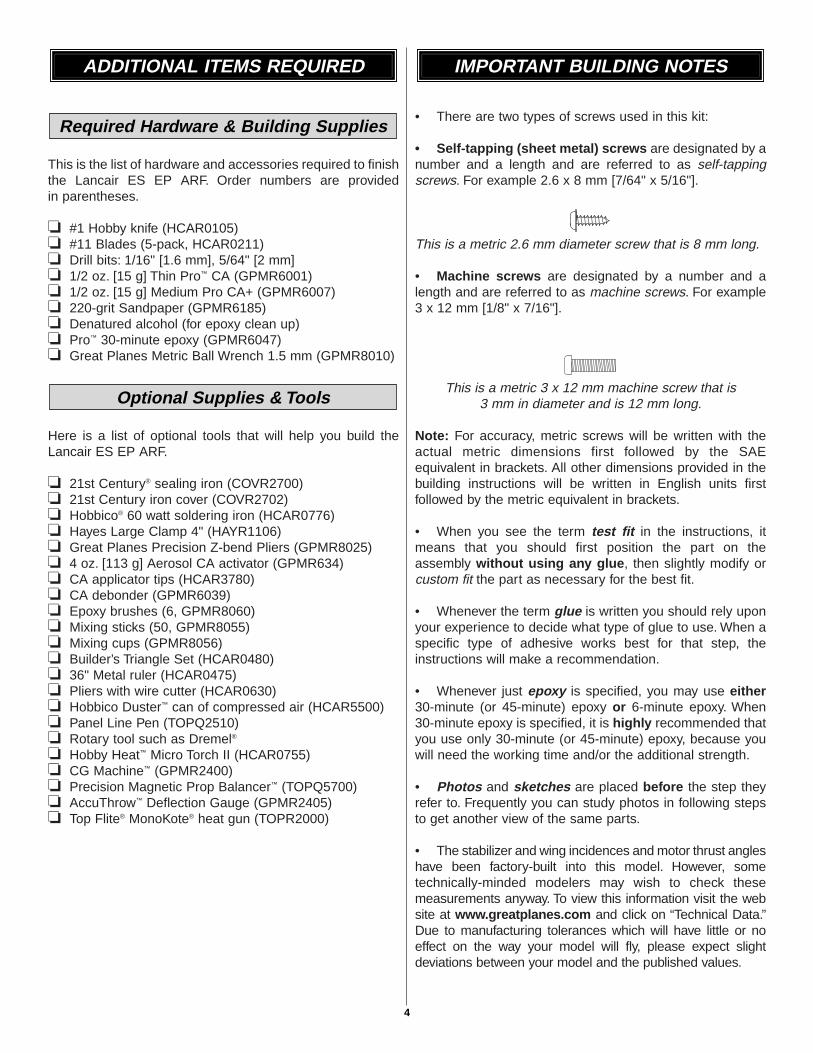
❏ 3. Make a 7/16" [11 mm] long mark 1/8" [3 mm] above thebottom of the hinge line on the left side of the rudder. Themark should be just behind the bevel on the leading edge ofthe rudder.
❏ 4. As you did with the elevator, use a hobby knife to cutout balsa from the line equal to the thickness of a controlhorn tab.
❏ 5. Test fit a control horn in the slot and press a backplateonto the tab. Trim off the excess tab protruding beyondthe backplate. If the backplate interferes with the fin whenthe rudder is deflected, mark the backplate where it needsto be trimmed. Do not glue the control horn to the rudderuntil instructed to do do.
❏ 6. Fit the rudder and fin into place by sliding it into the slotin the fuselage above the stabilizer. The aft end of the fin fitsinto the fuselage just behind the elevator control horn. Usea pen to mark lines where the fin fits into the fuselage aswell as where it sits on top of the stabilizer.
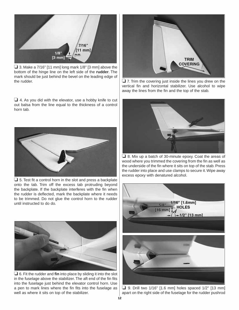
❏ 7. Trim the covering just inside the lines you drew on thevertical fin and horizontal stabilizer. Use alcohol to wipeaway the lines from the fin and the top of the stab.
❏ 8. Mix up a batch of 30-minute epoxy. Coat the areas ofwood where you trimmed the covering from the fin as well asthe underside of the fin where it sits on top of the stab. Pressthe rudder into place and use clamps to secure it.Wipe awayexcess epoxy with denatured alcohol.
❏ 9. Drill two 1/16" [1.6 mm] holes spaced 1/2" [13 mm]apart on the right side of the fuselage for the rudder pushrod
12

slot. The forward hole should be inline with the leading edgeof the stab and 5/8" [16 mm] below it as shown in the picture.Use a hobby knife to carve out the material between theholes to finish the pushrod exit slot. Test fit the rudderpushrod through the fuselage exiting out of the slot andmake any adjustments to the slot as necessary to preventthe pushrod from rubbing.
❏ 10. Remove the control horn from the rudder. Trim off theouter two holes so that the control horn will clear the elevator. Ifyou made a mark on the backplate to trim it, do so now.
❏ 11. Slide the rudder pushrod through the fuselage withthe Z-bend exiting out of the slot. Connect the Z-bend in thepushrod to the outer hole on the control horn. Reinsert thecontrol horn into the rudder adding a bit of medium CA to thebase of the control horn tab. Press on the control hornbackplate and add a drop of CA to secure it in place.
❏ 1. Glue the carbon wing joiner tube evenly spaced intothe fuselage. Test fit the wings onto the tube before gluing itto be sure the tube is centered.
❏ 2. Use sandpaper to roughen up the portion of the wingjoiner rod that is inside of the fuse. Use alcohol to clean therod. Glue the radio tray brace to the top of the wing joinertube as shown.
❏ 3. Press the tab on the vertical radio tray support intothe slot between the circle cutouts in the radio tray and glueit into place.
❏ 4. As you did with the wing joiner rod, sand the inside of thefuselage where the radio tray is going to be installed. Usealcohol to thoroughly clean the area. Epoxy the radio trayassembly into the fuselage. The vertical radio tray supportshould be positioned just behind the wing leading edge.
Install the Radio Tray & Wing Joiner Tube
ASSEMBLE THE FUSELAGE
13

❏ 1. Make a center mark on both sides of the wheel cutoutson all three wheel pants.
❏ 2. Cut slots at these marks 3/32" [2.4 mm]-wide and 1/4"[6 mm] deep.
❏ 3. Attach the wheels to the landing gear wires by slidingon a plastic wheel retainer, wheel, and another wheelretainer onto each wire.
❏ 4. Insert the landing gear wires into the slots you cut inthe wheel pants as shown.
❏ 5. Use fine sandpaper to roughen up the area around thebend in the landing gear wire on the wheel pants as well asthe wheel pant straps. Clean those areas with denaturedalcohol and use medium CA to glue the straps over thelanding gear wires onto the wheel pants. Be sure the landinggear wires are secured perpendicular to the bottom of thepants. Add a drop or two of medium or thick CA to the otherend of the landing gear wires where it contacts the pants. Besure to make a left and right landing gear.
❏ 6. The nose gear wheel pant is installed the same way,and should be glued to the left side of the nose gear wire.
Assemble the Landing Gear
14
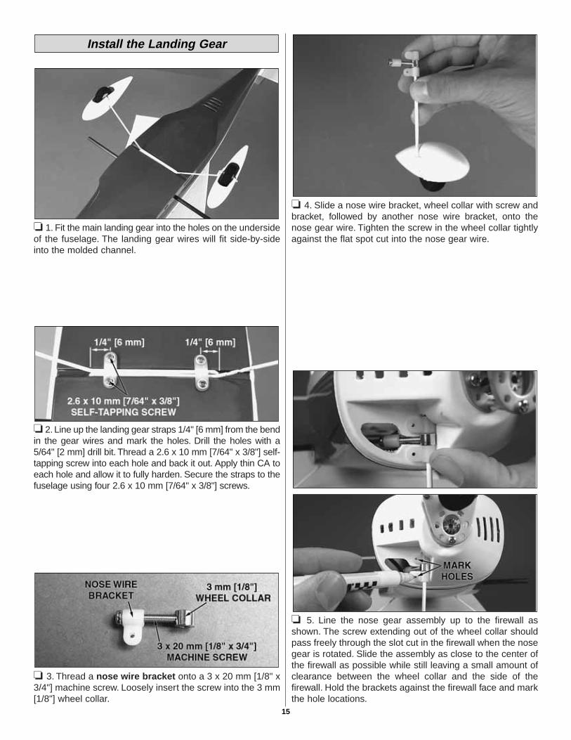
❏ 1. Fit the main landing gear into the holes on the undersideof the fuselage. The landing gear wires will fit side-by-sideinto the molded channel.
❏ 2. Line up the landing gear straps 1/4" [6 mm] from the bendin the gear wires and mark the holes. Drill the holes with a5/64" [2 mm] drill bit. Thread a 2.6 x 10 mm [7/64" x 3/8"] self-tapping screw into each hole and back it out. Apply thin CA toeach hole and allow it to fully harden. Secure the straps to thefuselage using four 2.6 x 10 mm [7/64" x 3/8"] screws.
❏ 3. Thread a nose wire bracket onto a 3 x 20 mm [1/8" x3/4"] machine screw. Loosely insert the screw into the 3 mm[1/8"] wheel collar.
❏ 4. Slide a nose wire bracket, wheel collar with screw andbracket, followed by another nose wire bracket, onto thenose gear wire. Tighten the screw in the wheel collar tightlyagainst the flat spot cut into the nose gear wire.
❏ 5. Line the nose gear assembly up to the firewall asshown. The screw extending out of the wheel collar shouldpass freely through the slot cut in the firewall when the nosegear is rotated. Slide the assembly as close to the center ofthe firewall as possible while still leaving a small amount ofclearance between the wheel collar and the side of thefirewall. Hold the brackets against the firewall face and markthe hole locations.
Install the Landing Gear
15
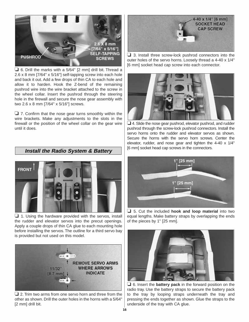
❏ 6. Drill the marks with a 5/64" [2 mm] drill bit. Thread a2.6 x 8 mm [7/64" x 5/16"] self-tapping screw into each holeand back it out. Add a few drops of thin CA to each hole andallow it to harden. Hook the Z-bend of the remainingpushrod wire into the wire bracket attached to the screw inthe wheel collar. Insert the pushrod through the steeringhole in the firewall and secure the nose gear assembly withtwo 2.6 x 8 mm [7/64" x 5/16"] screws.
❏ 7. Confirm that the nose gear turns smoothly within thewire brackets. Make any adjustments to the slots in thefirewall or the position of the wheel collar on the gear wireuntil it does.
❏ 1. Using the hardware provided with the servos, installthe rudder and elevator servos into the precut openings.Apply a couple drops of thin CA glue to each mounting holebefore installing the servos. The outline for a third servo bayis provided but not used on this model.
❏ 2. Trim two arms from one servo horn and three from theother as shown. Drill the outer holes in the horns with a 5/64"[2 mm] drill bit.
❏ 3. Install three screw-lock pushrod connectors into theouter holes of the servo horns. Loosely thread a 4-40 x 1/4"[6 mm] socket head cap screw into each connector.
❏ 4. Slide the nose gear pushrod, elevator pushrod, and rudderpushrod through the screw-lock pushrod connectors. Install theservo horns onto the rudder and elevator servos as shown.Secure the horns with the servo horn screws. Center theelevator, rudder, and nose gear and tighten the 4-40 x 1/4"[6 mm] socket head cap screws in the connectors.
❏ 5. Cut the included hook and loop material into twoequal lengths. Make battery straps by overlapping the endsof the pieces by 1" [25 mm].
❏ 6. Insert the battery pack in the forward position on theradio tray. Use the battery straps to secure the battery packto the tray by looping straps underneath the tray andpressing the ends together as shown. Glue the straps to theunderside of the tray with CA glue.
Install the Radio System & Battery
16

❏ 7. Sand the left side of the fuselage above the batterypack. Clean that area with denatured alcohol. Brush a lightcoat of epoxy onto the sanded area. This will provide asmooth surface for the electronic speed control (ESC) toadhere to. Connect the motor leads to the red and blackfemale bullet ends on the ESC. Use a piece of double-sidedtape to secure the ESC on/off switch to the inside of thefuselage. Be sure that the switch or switch leads do notinterfere with the servos or pushrods.
❏ 8. Repeat this procedure on the other side of the fuselagefor the receiver. Connect the ESC, rudder and elevatorservos, and a dual servo extension for the ailerons to thereceiver and secure it inside the fuselage.
❏ 9. Route the antenna out of the way from the pushrods. Itcan be secured on the outside of model. However, for aclean look, we drilled a hole in the bottom of the fuselage atthe back and ran the antenna out the hole.
❏ 1. Prepare the wing tips by sanding the inside edges ofthe tips as well as scuffing up the covering at the ends of thewing panels. Clean these surfaces with denatured alcohol.
❏ 2. Mix up some 30-minute epoxy and coat a 1/4" [6 mm]-wide strip around the inside edges of the wing tips. Fit thewing tips to the ends of the wings with the curves pointingup and tape them into position while the epoxy cures. Besure that the tips do not interfere with the movements of theailerons. Excess epoxy can be wiped away with alcohol.
❏ 3. The preferred method of attaching the wings to thefuselage is to glue them permanently with epoxy. The wingshave also been designed to be removable for ease oftransport if necessary. If you epoxy the wing panels to thefuselage, thoroughly coat the carbon wing joiner tube as wellas the root ribs on the panels with epoxy, and roughen themating area on the fuselage with sandpaper and clean itwith alcohol. Slide the panels in place and tape them to thefuselage while the epoxy cures.
Note: If you have glued the wing panels to the fuselage, skipsteps #4 and #5.
❏ 4. To bolt the wings to the fuselage, locate the two 2-56 x1" [25 mm] threaded rods and lightly coat one half of eachrod with epoxy. Before the epoxy cures, thread the rods intothe blind nuts in the wing panels in the location shown.Leave 1/2" [13 mm] of each rod protruding out of the wings.
❏ 5. Connect an additional servo extension to one of theaileron servo leads and secure the connection with heat-shrink tubing or tape. The servo extension is necessary if youare using the Futaba 6" [150 mm] dual servo extension. Sincemost micro servo models have shorter 5" [128 mm] servoleads, they are not long enough to reach the dual servo slots.If you purchased a standard Y-harness from anothermanufacturer, you may not need an additional servo extension.
Attach the Wing Panels
FINISH THE MODEL
17

❏ 6. Slide the wing panels onto the wing joiner tube andpush them firmly into place. Loosely thread a 4-40 x 1/4" [6 mm] SHCS into two 3/32" [2.4 mm] wheel collars. Tightenthe wheel collars onto the threaded rods in the wingsagainst the fuselage side.
❏ 7. Connect the aileron servo leads to the Y-harness ordual servo extension.
❏ 1. Trim the canopy along the molded cut lines. Usesandpaper to smooth the cut edges.
❏ 2. Cut a 1/2" x 1" [13 x 25 mm] piece of clear decal from thedecal sheet and use it to tape the front of the canopy to thefuselage. Applying the decal piece in this location will bettersecure the canopy, but still allow it to open and close easily.
❏ 3. Slide the cowl onto the front of the fuselage and makea mark where it should be trimmed for the nose gear.
❏ 4.Cut a slot at the mark slightly wider than the nose gear.Testfit the cowl to the fuselage and adjust the slot as necessary untilthe nose gear wire fits in the slot without touching.
❏ 5. While holding the cowl in place with the paint schemealigned, drill four evenly spaced 5/64" [2 mm] holes 3/16"[4.8 mm] from the back edge of the cowl as shown.Reinforce the holes with thin CA glue. Attach the cowl to thefuselage with four 2.6 x 8 mm [7/64" x 5/16"] self-tappingscrews. For a cleaner look, the cowl can be attached to thefuselage with silicone adhesive. If adhesive is used, be surethat the cowl is properly secured before each flight.
Note: Silicone adhesive will allow the cowl to be removed inthe future if you need to replace the motor or gears. Only acouple of dots of adhesive are required to secure the cowl.Make sure you roughen the area with sandpaper on the fuseand cowl, then clean it with alcohol.
Attach the Canopy & Cowl
18

❏ 1. Confirm that the set screw holding the prop adapter tothe gearbox shaft is tight using a 1.5 mm [1/16"] allenwrench. Slide the spinner backplate, propeller, and propwasher onto the prop adapter. Tighten the assembly withthe 3 x 12 mm [1/8" x 1/2"] propeller machine screw.
❏ 2. Attach the spinner cone to the spinner backplate usingthe 2.6 x 8 mm [7/64" x 5/16"] self-tapping spinner screws.
1. Use scissors or a sharp hobby knife to cut the decals fromthe sheet.
2. Be certain the model is clean and free from oily fingerprintsand dust. Prepare a dishpan or small bucket with a mixture ofliquid dish soap and warm water–about one teaspoon of soapper gallon of water. Submerse the decal in the soap and waterand peel off the paper backing. Note: Even though the decalshave a “sticky-back” and are not the water transfer type,submersing them in soap and water allows accurate positioningand reduces air bubbles underneath.
3. Position decal on the model where desired. Holding thedecal down, use a paper towel to wipe most of the water away.
4. Use a piece of soft balsa or something similar tosqueegee remaining water from under the decal. Apply therest of the decals the same way.
❏ 1. Turn on the transmitter and receiver and center thetrims. If necessary, remove the servo arms from the servosand reposition them so they are centered. Reinstall thescrews that hold on the servo arms.
❏ 2. With the transmitter and receiver still on, check all thecontrol surfaces to see if they are centered. If necessary,adjust the pushrods in the screw-lock pushrod connectors tocenter the control surfaces.
❏ 3. Make certain that the control surfaces and the throttlerespond in the correct direction as shown in the diagram. Ifany of the controls respond in the wrong direction, use theservo reversing in the transmitter to reverse the servosconnected to those controls. Be certain the control surfaceshave remained centered. Adjust if necessary.
Use a Great Planes AccuThrow (or a ruler) to accuratelymeasure and set the control throw of each control surface asindicated in the chart on page 20.
Note: The throws are measured at the widest part of theelevator, rudder and ailerons.
Set the Control Throws
FULL THROTTLE
RUDDER MOVES RIGHT
LEFT AILERON MOVES DOWNRIGHT AILERON MOVES UP
ELEVATOR MOVES UP
4-CHANNELTRANSMITTER
(STANDARD MODE 2)4-CHANNEL RADIO SETUP
TRANSMITTER4-CHANNEL
TRANSMITTER4-CHANNEL
TRANSMITTER4-CHANNEL
Check the Control Directions
GET THE MODEL READY TO FLY
Apply the Decals
Attach the Propeller & Spinner
19

At this stage the model should be in ready-to-fly conditionwith all of the systems in place including the engine, landinggear, covering and paint, and the radio system.
❏ 1. Use a felt-tip pen or 1/8" [3 mm]-wide tape to accuratelymark the C.G. on the top of the wing on both sides of thefuselage. The balance point should be measured at thefuselage. The C.G. is located 2" [50 mm] back from the leadingedge of the wing at the fuselage.
❏ 2. With the wing attached to the fuselage and the batterypack installed, place the model upside-down on a GreatPlanes CG Machine, or lift it upside-down at the balancepoint you marked.
❏ 3. If the tail drops, the model is “tail heavy” and the batterypack and/or receiver must be shifted forward to balance. If thenose drops, the model is “nose heavy” and the battery packand/or receiver must be shifted aft to balance.
❏ 4. IMPORTANT: After you have shifted the radio gear,recheck the C.G.
❏ 5. If you use a different battery pack it will be necessaryto recheck the C.G.
❏ 1. With the wing level, lift the model by the motor propellershaft and the bottom of the fuse under the TE of the fin. Dothis several times.
❏ 2. If one wing always drops when you lift the model, it meansthat side is heavy. Balance the airplane by adding weight to theother wing tip. An airplane that has been laterally balancedwill track better in loops and other maneuvers.
No matter if you fly at an AMA sanctioned R/C club site or ifyou fly somewhere on your own, you should always haveyour name, address, telephone number and AMA numberon or inside your model. It is required at all AMA R/C clubflying sites and AMA sanctioned flying events. Fill out theidentification tag on the back cover page (or on the decalsheet) and place it on or inside your model.
Identify Your Model
PREFLIGHT
Balance the Model Laterally
This is where your model should balance for the firstflights. Later, you may wish to experiment by shifting theC.G. up to 1/4" [6 mm] forward or 1/8" [3 mm] back tochange the flying characteristics. Moving the C.G. forwardmay improve the smoothness and stability, but the modelmay then require more speed for takeoff and make it moredifficult to slow for landing. Moving the C.G. aft makes themodel more maneuverable, but could also cause it tobecome too difficult to control. In any case, start at therecommended balance point and do not at any timebalance the model outside the specified range.
More than any other factor, the C.G. (balance point) canhave the greatest effect on how a model flies, and maydetermine whether or not your first flight will besuccessful. If you value this model and wish to enjoy it formany flights, DO NOT OVERLOOK THIS IMPORTANTPROCEDURE. A model that is not properly balanced willbe unstable and possibly unflyable.
Balance the Model (C.G.)
IMPORTANT: The Lancair EP has been extensively flownand tested to arrive at the throws at which it flies best. Flyingyour model at these throws will provide you with the greatestchance for successful first flights. If, after you have becomeaccustomed to the way the Lancair EP flies, you would like tochange the throws to suit your taste, that is fine. However, toomuch control throw could make the model difficult to control,so remember, “more is not always better.”
These are the recommended control surface throws:
ELEVATOR: 3/8" [10 mm] up3/8" [10 mm] down
RUDDER: 1/2" [13 mm] right1/2" [13 mm] left
AILERONS: 3/8" [10 mm] up3/8" [10 mm] down
20

Follow the battery charging instructions that came with yourradio control system to charge the batteries. You shouldalways charge your transmitter and motor batteries the nightbefore you go flying, and at other times as recommended bythe radio manufacturer.
The included 1800mAh NiMH battery pack should becharged by a NiMH-compatible charger at no more than1.5A. Compatible chargers available are listed on page 4 ofthis manual.
At the 1.5A charge rate, the battery pack should take a littlemore than one hour to charge when fully depleted. Ratesless than 1.5A will take longer to completely charge thepack. The fully charged battery pack voltage should notexceed 12V.
Always monitor the battery pack during a charge. Thepack may get warm during charging but should not gethotter than 125°F. If the pack gets too hot, disconnect itfrom the charger and allow it to cool.
Carefully balance your propeller and spare propellers beforeyou fly. An unbalanced prop can be the single mostsignificant cause of vibration that can damage your model.Not only will engine mounting screws and bolts loosen,possibly with disastrous effect, but vibration may alsodamage your radio receiver and battery.
We use a Top Flite Precision Magnetic Prop Balancer™
(TOPQ5700) in the workshop and keep a Great PlanesFingertip Prop Balancer (GPMQ5000) in our flight box.
After you test the operation of the motor on the model,inspect the model closely to make sure all screws remainedtight, the hinges are secure, the prop is secure and allpushrods and connectors are secure.
Ground check the operational range of your radio before thefirst flight of the day. With the transmitter antenna collapsedand the ESC and transmitter on, you should be able to walkat least 100 feet [30 m] away from the model and still havecontrol. Have an assistant stand by your model and, whileyou work the controls, tell you what the control surfaces aredoing. Repeat this test with the motor running at variousspeeds with an assistant holding the model, using handsignals to show you what is happening. If the controlsurfaces do not respond correctly, do not fly! Find andcorrect the problem first. Look for loose servo connections orbroken wires, corroded wires on old servo connectors, poorsolder joints in your battery pack or a defective cell, or adamaged receiver crystal from a previous crash.
Use safety glasses when running motors.
Do not run the motor in an area of loose gravel or sand; thepropeller may throw such material in your face or eyes.
Keep your face and body as well as all spectators away fromthe plane of rotation of the propeller as you run the motor.
Keep these items away from the prop: loose clothing, shirtsleeves, ties, scarfs, long hair or loose objects such aspencils or screwdrivers that may fall out of shirt or jacketpockets into the prop.
The motor gets hot! Do not touch it during or rightafter operation.
Failure to follow these safety precautions may resultin severe injury to yourself and others.
MOTOR SAFETY PRECAUTIONS
Range Check
Ground Check
Balance the Propellers
CAUTION: Unless the instructions that came with yourradio system state differently, the initial charge on a newtransmitter battery should be done for 15 hours using theslow-charger that came with the radio system. This will“condition” the battery so that the next charge may bedone using the fast-charger of your choice. If the initialcharge is done with a fast-charger the batteries may notreach their full capacity and you may be flying withbatteries that are only partially charged.
Charge the Batteries
21

Read and abide by the following excerpts from the Academyof Model Aeronautics Safety Code. For the complete SafetyCode refer to Model Aviation magazine, the AMA web site orthe Code that came with your AMA license.
1) I will not fly my model aircraft in sanctioned events, air shows,or model flying demonstrations until it has been proven to beairworthy by having been previously, successfully flight tested.
2) I will not fly my model aircraft higher than approximately400 feet within 3 miles of an airport without notifying theairport operator. I will give right-of-way and avoid flying in theproximity of full-scale aircraft. Where necessary, an observershall be utilized to supervise flying to avoid having modelsfly in the proximity of full-scale aircraft.
3) Where established, I will abide by the safety rules for theflying site I use, and I will not willfully and deliberately fly mymodels in a careless, reckless and/or dangerous manner.
5) I will not fly my model unless it is identified with my nameand address or AMA number, on or in the model. Note: Thisdoes not apply to models while being flown indoors.
7) I will not operate models with pyrotechnics (any devicethat explodes, burns, or propels a projectile of any kind).
1) I will have completed a successful radio equipment groundcheck before the first flight of a new or repaired model.
2) I will not fly my model aircraft in the presence ofspectators until I become a qualified flier, unless assisted byan experienced helper.
3) At all flying sites a straight or curved line(s) must beestablished in front of which all flying takes place with theother side for spectators. Only personnel involved with flyingthe aircraft are allowed at or in the front of the flight line.Intentional flying behind the flight line is prohibited.
4) I will operate my model using only radio control frequenciescurrently allowed by the Federal Communications Commission.
5) I will not knowingly operate my model within threemiles of any pre-existing flying site except inaccordance with the frequency sharing agreementlisted [in the complete AMA Safety Code].
9) Under no circumstances may a pilot or other person toucha powered model in flight; nor should any part of themodel other than the landing gear, intentionally touchthe ground, except while landing.
❏ 1. Check the C.G. according to the measurementsprovided in the manual.
❏ 2. Be certain the battery and receiver are securelymounted in the fuse. Simply stuffing them into placewith foam rubber is not sufficient.
❏ 3. Extend your receiver antenna and make sure it has astrain relief inside the fuselage to keep tension off thesolder joint inside the receiver.
❏ 4. Balance your model laterally as explained inthe instructions.
❏ 5. Add a drop of oil to the axles so the wheels willturn freely.
❏ 6. Make sure all control surfaces are secure.❏ 7. Reinforce holes for wood screws with thin CA where
appropriate (servo mounting screws, cowl mountingscrews, etc.).
❏ 8. Confirm that all controls operate in the correct directionand the throws are set up according to the manual.
❏ 9. Make sure all servo arms are secured to the servoswith the screws included with your radio.
❏ 10. Secure connections between servo wires andY-connectors or servo extensions, and the connectionbetween your battery pack and the on/off switch withvinyl tape, heat-shrink tubing or special clips suitablefor that purpose.
❏ 11. Make sure any servo extension cords you may haveused do not interfere with other systems (servo arms,pushrods, etc.).
❏ 12. Balance your propeller (and spare propellers).❏ 13. Tighten the propeller screw and spinner.❏ 14. Place your name, address, AMA number and
telephone number on or inside your model.❏ 15. If you wish to photograph your model, do so before
your first flight.❏ 16. Range check your radio when you get to the flying field.
During the last few moments of preparation your mind maybe elsewhere anticipating the excitement of the first flight.Because of this, you may be more likely to overlook certainchecks and procedures that should be performed before themodel is flown. To help avoid this, a check list is provided tomake sure these important areas are not overlooked. Manyare covered in the instruction manual, so where appropriate,refer to the manual for complete instructions. Be sure tocheck the items off as they are completed.
CHECK LIST
Radio Control
General
AMA SAFETY CODE (excerpts)
22
The Lancair ES EP ARF is a great-flying model that fliessmoothly and predictably. The Lancair does not, however,possess the self-recovery characteristics of a primary R/Ctrainer and should be flown only by experienced R/C pilots.
CAUTION: While setting up and checking the control throwson your airplane. remove the propeller from the motor.
1. Plug the servo connector from your speed control intothe throttle socket of your receiver.
2. Connect the motor battery to the speed control.
3. Move the throttle stick to idle (towards you).
4. Switch on the transmitter then the speed control.
5. Move the throttle stick to full power (away from you) forat least 2 seconds.
6. Move the throttle stick back to idle (toward you). Thespeed control is now ready to operate. Note: If the motordoes not start as the throttle is advanced, you may needto reverse the servo throw setting of the throttle.
7. As a safety precaution to prevent the motor from startingwhen the speed control is first switched on, you willneed to move the throttle to full and back to idle everytime the speed control is switched on.
Before you get ready to take off, see how the model handleson the ground by doing a few practice runs at low speeds onthe runway. Remember to take off into the wind. When you’reready, point the model straight down the runway, thengradually advance the throttle. As the model gains speed, thenose will lift off the ground. Gain as much speed as yourrunway and flying site will practically allow before gentlyapplying up elevator, lifting the model into the air. Be smoothon the elevator stick, allowing the model to establish a gentleclimb to a safe altitude before turning into the traffic pattern.
For reassurance and to keep an eye on other traffic, it is agood idea to have an assistant on the flight line with you. Tellhim to remind you to throttle back once the plane gets to acomfortable altitude. While full throttle is usually desirable fortakeoff, most models fly more smoothly at reduced speeds.
Take it easy with the Lancair ES EP ARF for the first fewflights, gradually getting acquainted with it as you gainconfidence. Adjust the trims to maintain straight and levelflight. After flying around for a while, and while still at a safealtitude, practice slow flight and execute practice landingapproaches by reducing the throttle to see how the modelhandles at slower speeds. Add power to see how she climbsas well. Continue to fly around, executing variousmaneuvers and making mental notes (or having yourassistant write them down) of what trim or C.G. changesmay be required to fine tune the model so it flies the way youlike. Mind your battery power, but use this first flight tobecome familiar with your model before landing.
To initiate a landing approach, lower the throttle while on thedownwind leg. Allow the nose of the model to pitchdownward to gradually bleed off altitude. Continue to losealtitude, but maintain airspeed by keeping the nose down asyou turn onto the crosswind leg. Make your final turn towardthe runway (into the wind) keeping the nose down tomaintain airspeed and control. Level the attitude when themodel reaches the runway threshold, modulating the throttleas necessary to maintain your glide path and airspeed. Ifyou are going to overshoot, smoothly advance the throttle(always ready on the right rudder to counteract torque) andclimb out to make another attempt. When you’re ready tomake your landing flare and the model is a foot or so off thedeck, smoothly increase up elevator until it gently touchesdown. Once the model is on the runway and has lost flyingspeed, slowly release up elevator to place the nose on theground, regaining steering control.
One final note about flying your model – have a goal or flightplan in mind for every flight. This can be learning a new
Landing
Flight
Takeoff
Speed Control Set-Up
CAUTION (THIS APPLIES TO ALL R/C AIRPLANES): If,while flying, you notice an alarming or unusual sound such asa low-pitched “buzz,” this may indicate control surface flutter.Flutter occurs when a control surface (such as an aileron orelevator) or a flying surface (such as a wing or stab) rapidlyvibrates up and down (thus causing the noise). In extremecases, if not detected immediately, flutter can actually causethe control surface to detach or the flying surface to fail, thuscausing loss of control followed by an impending crash. Thebest thing to do when flutter is detected is to slow the modelimmediately by reducing power, then land as soon as safelypossible. Identify which surface fluttered (so the problem maybe resolved) by checking all the servo grommets fordeterioration or signs of vibration. Make certain all pushrodlinkages are secure and free of play. If it fluttered once, undersimilar circumstances it will probably flutter again unless theproblem is fixed. Some things which can cause flutter are;Excessive hinge gap; Not mounting control horns solidly; Poorfit of clevis pin in horn; Side-play of wire pushrods caused bylarge bends; Excessive free play in servo gears; Insecureservo mounting; and one of the most prevalent causes offlutter; Flying an over-powered model at excessive speeds.
FLYING
23

maneuver(s), improving a maneuver(s) you already know, orlearning how the model behaves in certain conditions (such ason high or low rates). This is not necessarily to improve yourskills (though it is never a bad idea!), but more importantly soyou do not surprise yourself by impulsively attempting amaneuver and suddenly finding that you’ve run out of time,altitude or airspeed. Every maneuver should be deliberate, notimpulsive. For example, if you’re going to do a loop, check youraltitude, mind the wind direction (anticipating rudder correctionsthat will be required to maintain heading), remember to throttleback at the top, and make certain you are on the desired rates(high/low rates). A flight plan greatly reduces the chances ofcrashing your model just because of poor planning andimpulsive moves. Remember to think.
Have a ball! But always stay in control and fly in asafe manner.
GOOD LUCK AND GREAT FLYING!
Make a copy of this identification tag and put it on orinside your model.