Embed Size (px)
Citation preview
ARIES-AT: An Advanced Tokamak, Advanced Technology
Fusion Power PlantFarrokh NajmabadiUniversity of California, San Diego, La Jolla, CA, United States of America
9th Course on Technology of Fusion Reactors 26 July – 1 August 2004 Erice Italy
Electronic Copy: ARIES Web Site: http://aries.ucsd.edu/PUBLIC
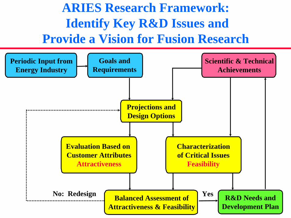
ARIES Research Framework:Identify Key R&D Issues and
Provide a Vision for Fusion ResearchScientific & Technical
AchievementsPeriodic Input from
Energy IndustryGoals and
Requirements
Evaluation Based on Customer Attributes
Attractiveness
Characterizationof Critical Issues
Feasibility
Projections andDesign Options
Balanced Assessment ofAttractiveness & Feasibility
R&D Needs andDevelopment Plan
No: Redesign Yes
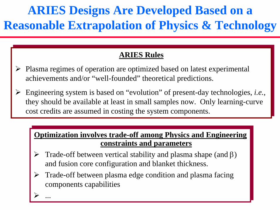
ARIES Designs Are Developed Based on a Reasonable Extrapolation of Physics & Technology
ARIES Rules
Plasma regimes of operation are optimized based on latest experimental achievements and/or “well-founded” theoretical predictions.
Engineering system is based on “evolution” of present-day technologies, i.e., they should be available at least in small samples now. Only learning-curve cost credits are assumed in costing the system components.
Optimization involves trade-off among Physics and Engineering constraints and parameters
Trade-off between vertical stability and plasma shape (and β) and fusion core configuration and blanket thickness.Trade-off between plasma edge condition and plasma facing components capabilities...
Optimization involves trade-off among Physics and Engineering constraints and parameters
Trade-off between vertical stability and plasma shape (and β) and fusion core configuration and blanket thickness.Trade-off between plasma edge condition and plasma facing components capabilities...
Customer Requirements

Top-Level Requirements for Fusion Power Plants Was Developed in Consultation with US Industry
Public Acceptance:No public evacuation plan is required: total dose < 1 rem at site boundary;Generated waste can be returned to environment or recycled in less than a few hundred years (not geological time-scale);No disturbance of public’s day-to-day activities;No exposure of workers to a higher risk than other power plants;
Public Acceptance:No public evacuation plan is required: total dose < 1 rem at site boundary;Generated waste can be returned to environment or recycled in less than a few hundred years (not geological time-scale);No disturbance of public’s day-to-day activities;No exposure of workers to a higher risk than other power plants;
Reliable Power Source:Closed tritium fuel cycle on site;Ability to operate at partial load conditions (50% of full power);Ability to maintain power core (availability > 80%);Ability to operate reliably with < 0.1 major unscheduled shut-down per year.
Reliable Power Source:Closed tritium fuel cycle on site;Ability to operate at partial load conditions (50% of full power);Ability to maintain power core (availability > 80%);Ability to operate reliably with < 0.1 major unscheduled shut-down per year.
Economic Competitiveness: Above requirements must be achieved simultaneously and consistent with a competitive life-cycle cost of electricity.
Economic Competitiveness: Above requirements must be achieved simultaneously and consistent with a competitive life-cycle cost of electricity.
Directions for Optimization
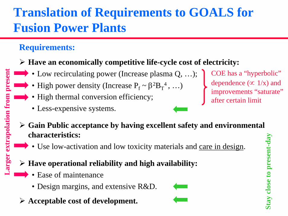
Translation of Requirements to GOALS for Fusion Power Plants
Requirements:
Have an economically competitive life-cycle cost of electricity:• Low recirculating power (Increase plasma Q, …);• High power density (Increase Pf ~ β2BT
4 , …)• High thermal conversion efficiency;• Less-expensive systems.
Gain Public acceptance by having excellent safety and environmental characteristics:• Use low-activation and low toxicity materials and care in design.
Have operational reliability and high availability: • Ease of maintenance• Design margins, and extensive R&D.
Acceptable cost of development.
COE has a “hyperbolic”dependence (∝ 1/x) andimprovements “saturate”after certain limit
Stay
clo
se to
pre
sent
-day
Lar
ger
extr
apol
atio
n fr
om p
rese
nt
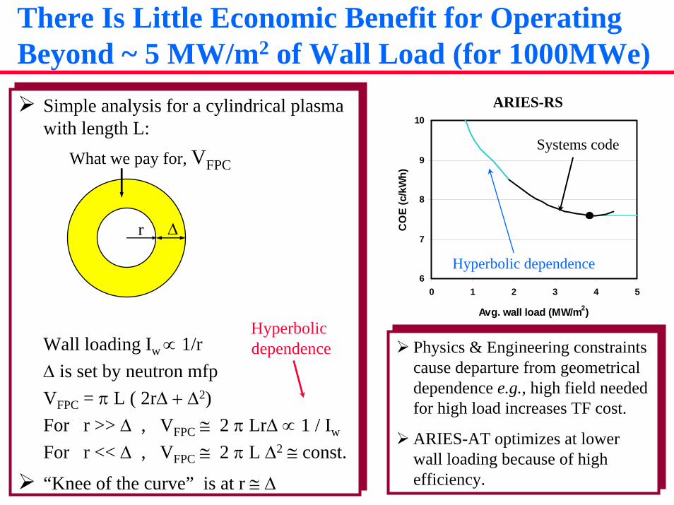
There Is Little Economic Benefit for Operating Beyond ~ 5 MW/m2 of Wall Load (for 1000MWe)
Simple analysis for a cylindrical plasma with length L:
Wall loading Iw ∝ 1/r ∆ is set by neutron mfp VFPC = π L ( 2r∆ + ∆2) For r >> ∆ , VFPC ≅ 2 π Lr∆ ∝ 1 / Iw
For r << ∆ , VFPC ≅ 2 π L ∆2 ≅ const.
“Knee of the curve” is at r ≅ ∆
Simple analysis for a cylindrical plasma with length L:
Wall loading Iw ∝ 1/r ∆ is set by neutron mfp VFPC = π L ( 2r∆ + ∆2) For r >> ∆ , VFPC ≅ 2 π Lr∆ ∝ 1 / Iw
For r << ∆ , VFPC ≅ 2 π L ∆2 ≅ const.
“Knee of the curve” is at r ≅ ∆
r ∆
What we pay for, VFPC
Hyperbolicdependence
6
7
8
9
10
0 1 2 3 4 5
Avg. wall load (MW/m2)
CO
E (c
/kW
h)
ARIES-RS
Systems code
Hyperbolic dependence
Physics & Engineering constraints cause departure from geometrical dependence e.g., high field needed for high load increases TF cost.
ARIES-AT optimizes at lower wall loading because of high efficiency.
Physics & Engineering constraints cause departure from geometrical dependence e.g., high field needed for high load increases TF cost.
ARIES-AT optimizes at lower wall loading because of high efficiency.

Continuity of ARIES research has led to the progressive refinement of research
ARIES-I (1990): • Trade-off of β with bootstrap• High-field magnets to compensate for low β
ARIES-II/IV, 2nd Stability (1992): • High β only with too much bootstrap• Marginal reduction in current-drive power
ARIES-RS, reverse shear (1996): • Improvement in β and current-drive power• Approaching COE insensitive of power density
ARIES-AT, reverse shear (2000): • Approaching COE insensitive of current-drive • High β is used to reduce toroidal field
Need high β equilibria with high bootstrap
Need high β equilibria with aligned bootstrap
Better bootstrap alignmentMore detailed physics
Impr
oved
Phy
sics
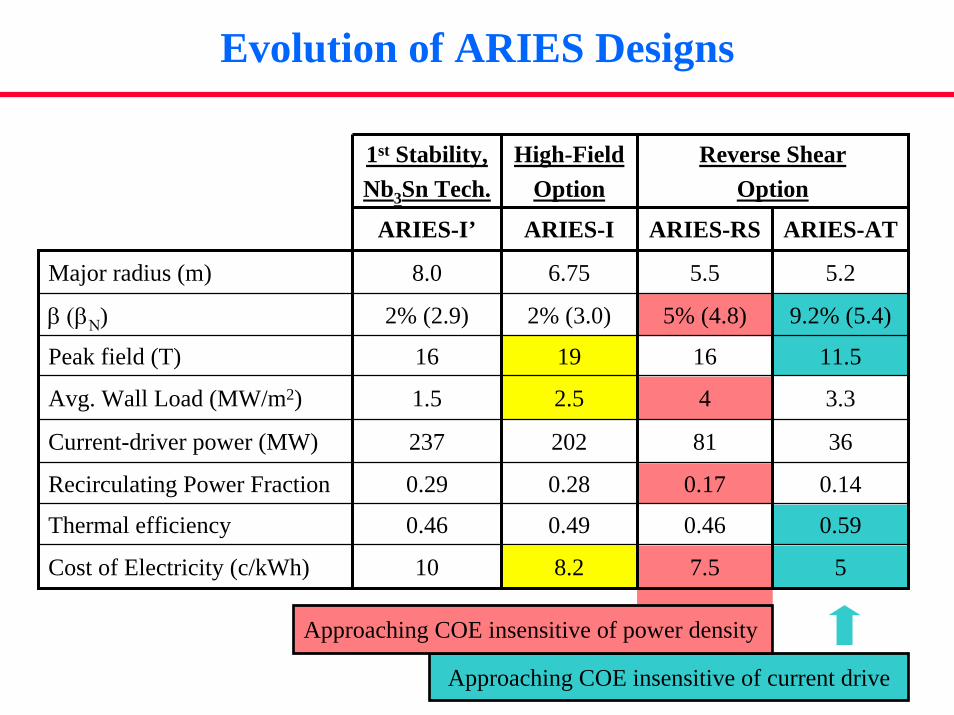
Evolution of ARIES Designs
Approaching COE insensitive of current drive
Approaching COE insensitive of power density
1st Stability, Nb3Sn Tech.
ARIES-I’
Major radius (m) 8.0
β (βΝ) 2% (2.9)
Peak field (T) 16
Avg. Wall Load (MW/m2) 1.5
Current-driver power (MW) 237
Recirculating Power Fraction 0.29
Thermal efficiency 0.46
Cost of Electricity (c/kWh) 10
Reverse Shear Option
High-FieldOption
ARIES-I
6.75
2% (3.0)
19
2.5
202
0.28
0.49
8.2
ARIES-RS
5.5
5% (4.8)
16
4
81
0.17
0.46
7.5
ARIES-AT
5.2
9.2% (5.4)
11.5
3.3
36
0.14
0.59
5
ARIES-ATPhysics Analysis
ARIES-AT: Physics Highlights
We used the lessons learned in ARIES-ST optimization to reach a higher performance plasma;∗ Using > 99% flux surface from free-boundary plasma
equilibria rather than 95% flux surface used in ARIES-RS leads to larger elongation and triangularity and higher stable β.
ARIES-AT blanket allows vertical stabilizing shell closer to the plasma, leading to higher elongation and higher β.
Detailed stability analysis indicated that Η−mode pressure & current profiles and X-point improves ballooning stability.
A kink stability shell (τ = 10 ms), 1 cm of tungsten behind the blanket, is utilized to keep the power requirements for n = 1 resistive wall mode feedback coil at a modest level.
ARIES-AT: Physics Highlights
We eliminated HHFW current drive and used only lower hybrid for off-axis current drive.
Self-consistent physics-based transport simulations indicated the optimized pressure and current profiles can be sustained with a peaked density profile.
A radiative divertor is utilized to keep the peak heat flux at the divertor at ~ 5 MW/m2.Accessible fueling; No ripple losses; 0-D consistent startup; etc.
As a whole, we performed detailed, self-consistent analysis of plasma MHD, current drive, transport, and divertor (using finiteedge density, finite p′, impurity radiation, etc.)
The ARIES-AT Equilibrium is the Results of Extensive ideal MHD Stability Analysis
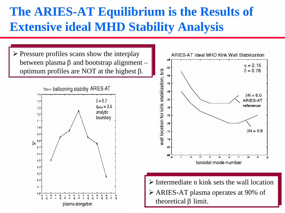
Pressure profiles scans show the interplay between plasma β and bootstrap alignment –optimum profiles are NOT at the highest β.
Pressure profiles scans show the interplay between plasma β and bootstrap alignment –optimum profiles are NOT at the highest β.
Intermediate n kink sets the wall locationARIES-AT plasma operates at 90% of theoretical β limit.
Intermediate n kink sets the wall locationARIES-AT plasma operates at 90% of theoretical β limit.

Vertical Stability and Control is a Critical Physics/Engineering Interface
ARIES-AT elongation of κ = 2.2 is consistent with allowed stabilizer location
ARIES-AT elongation of κ = 2.2 is consistent with allowed stabilizer location
TSC nonlinear dynamic simulations of vertical stability and feedback control show the tradeoff of power and accessible plasmas
TSC nonlinear dynamic simulations of vertical stability and feedback control show the tradeoff of power and accessible plasmas
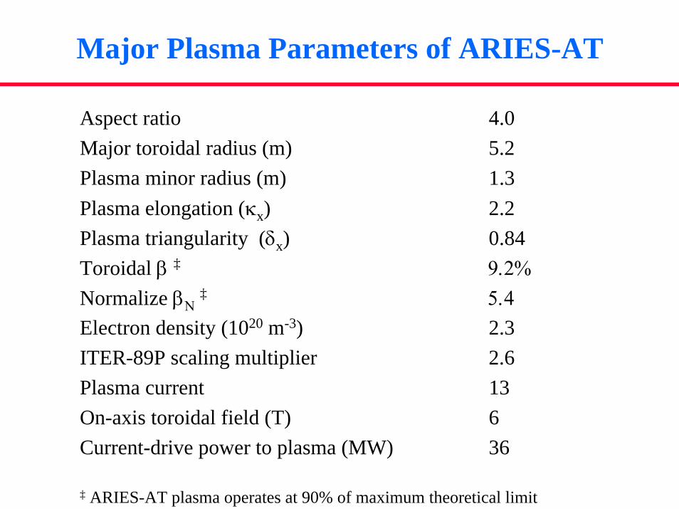
Major Plasma Parameters of ARIES-AT
Aspect ratio 4.0Major toroidal radius (m) 5.2Plasma minor radius (m) 1.3Plasma elongation (κx) 2.2Plasma triangularity (δx) 0.84Toroidal β ‡ 9.2%Normalize βΝ
‡ 5.4Electron density (1020 m-3) 2.3ITER-89P scaling multiplier 2.6Plasma current 13On-axis toroidal field (T) 6Current-drive power to plasma (MW) 36
‡ ARIES-AT plasma operates at 90% of maximum theoretical limit
ARIES-ATEngineering Analysis
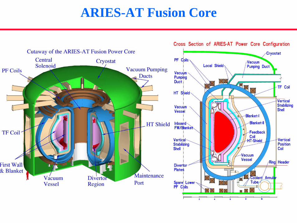
ARIES-AT Fusion Core

Fusion Core Is Segmented to Minimize the Rad-Waste
Only “blanket-1” and divertors are replaced every 5 years
Only “blanket-1” and divertors are replaced every 5 years
Blanket 1 (replaceable)Blanket 2 (lifetime)
Shield (lifetime)
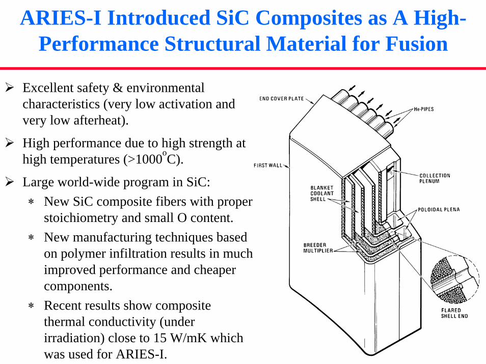
ARIES-I Introduced SiC Composites as A High-Performance Structural Material for Fusion
Excellent safety & environmental characteristics (very low activation and very low afterheat).
High performance due to high strength at high temperatures (>1000oC).
Large world-wide program in SiC:∗ New SiC composite fibers with proper
stoichiometry and small O content.∗ New manufacturing techniques based
on polymer infiltration results in much improved performance and cheaper components.
∗ Recent results show composite thermal conductivity (under irradiation) close to 15 W/mK which was used for ARIES-I.
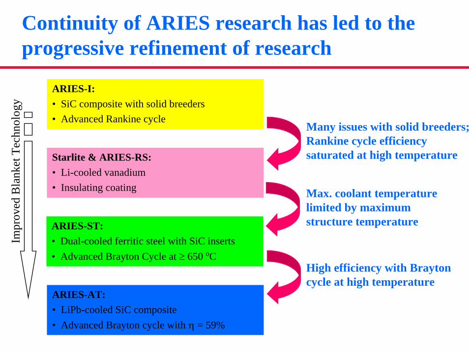
Continuity of ARIES research has led to the progressive refinement of research
ARIES-I: • SiC composite with solid breeders• Advanced Rankine cycle
Starlite & ARIES-RS:• Li-cooled vanadium• Insulating coating
ARIES-ST: • Dual-cooled ferritic steel with SiC inserts• Advanced Brayton Cycle at ≥ 650 oC
ARIES-AT: • LiPb-cooled SiC composite • Advanced Brayton cycle with η = 59%
Many issues with solid breeders; Rankine cycle efficiency saturated at high temperature
Max. coolant temperature limited by maximum structure temperature
High efficiency with Braytoncycle at high temperature
Impr
oved
Bla
nket
Tec
hnol
ogy
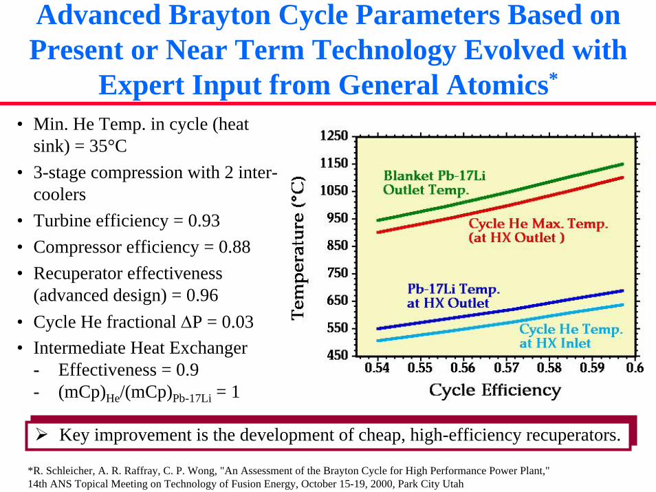
Advanced Brayton Cycle Parameters Based on Present or Near Term Technology Evolved with
Expert Input from General Atomics*
*R. Schleicher, A. R. Raffray, C. P. Wong, "An Assessment of the Brayton Cycle for High Performance Power Plant," 14th ANS Topical Meeting on Technology of Fusion Energy, October 15-19, 2000, Park City Utah
• Min. He Temp. in cycle (heat sink) = 35°C
• 3-stage compression with 2 inter-coolers
• Turbine efficiency = 0.93• Compressor efficiency = 0.88• Recuperator effectiveness
(advanced design) = 0.96• Cycle He fractional ∆P = 0.03• Intermediate Heat Exchanger
- Effectiveness = 0.9- (mCp)He/(mCp)Pb-17Li = 1
Key improvement is the development of cheap, high-efficiency recuperators.Key improvement is the development of cheap, high-efficiency recuperators.
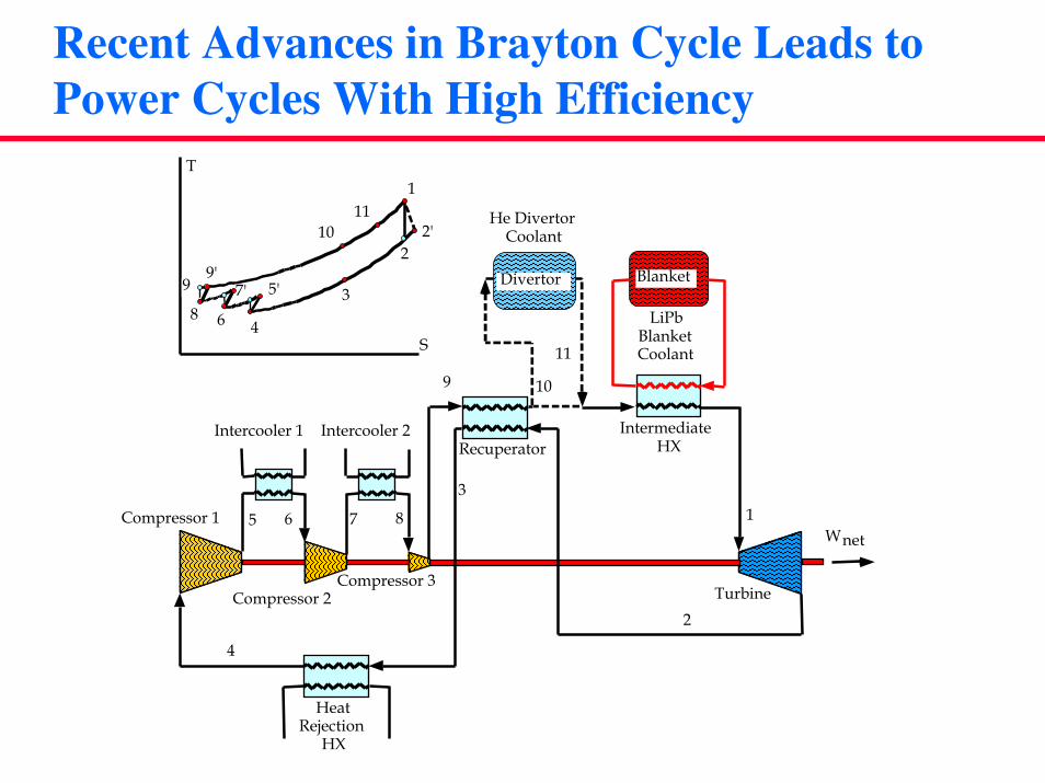
Recent Advances in Brayton Cycle Leads to Power Cycles With High Efficiency
RecuperatorIntercooler 1 Intercooler 2
Compressor 1
Compressor 2Compressor 3
HeatRejection
HX
Wnet
Turbine
Blanket
IntermediateHX
5'
1
22'
38
9
4
7'9'
10
6
T
S
1
2
3
4
5 6 7 8
9 10
Divertor
LiPbBlanketCoolant
He DivertorCoolant
11
11
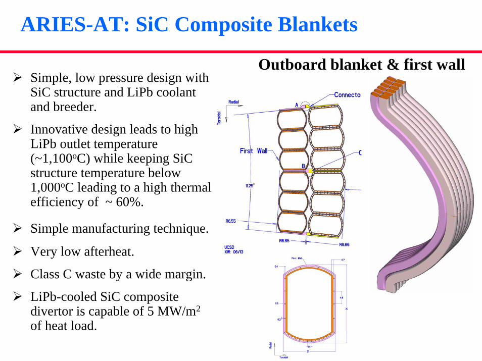
ARIES-AT: SiC Composite Blankets
Outboard blanket & first wallSimple, low pressure design with SiC structure and LiPb coolant and breeder.
Innovative design leads to high LiPb outlet temperature (~1,100oC) while keeping SiCstructure temperature below 1,000oC leading to a high thermal efficiency of ~ 60%.
Simple manufacturing technique.
Very low afterheat.
Class C waste by a wide margin.
LiPb-cooled SiC composite divertor is capable of 5 MW/m2
of heat load.

Develop Plausible Fabrication Procedure and Minimize Joints in High Irradiation Region
1 2 3 4 5
1. Manufacture separate halves of the SiCf/SiC poloidal module by SiCf weaving and SiC Chemical Vapor Infiltration (CVI) or polymer process;
2. Manufacture curved section of inner shell in one piece by SiCf weaving and SiCChemical Vapor Infiltration (CVI) or polymer process;
3. Slide each outer shell half over the free-floating inner shell;
4. Braze the two half outer shells together at the midplane;
5. Insert short straight sections of inner shell at each end;
Butt joint Mortise and tenon joint
Lap joint Tapered butt joint
Double lap joint Tapered lap joint
Brazing procedure selected for reliable joint contact area
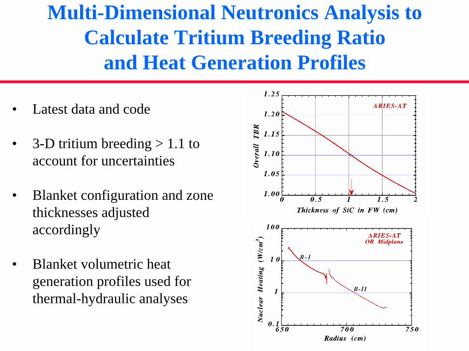
Multi-Dimensional Neutronics Analysis to Calculate Tritium Breeding Ratio
and Heat Generation Profiles
• Latest data and code
• 3-D tritium breeding > 1.1 to account for uncertainties
• Blanket configuration and zone thicknesses adjusted accordingly
• Blanket volumetric heat generation profiles used for thermal-hydraulic analyses
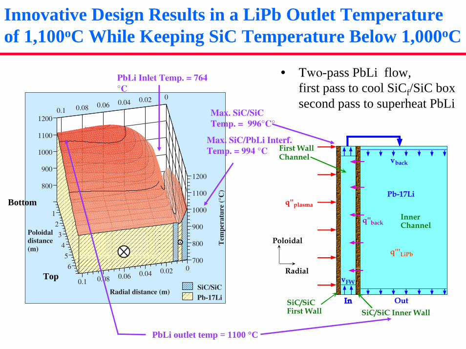
Innovative Design Results in a LiPb Outlet Temperature of 1,100oC While Keeping SiC Temperature Below 1,000oC
• Two-pass PbLi flow, first pass to cool SiCf/SiC box second pass to superheat PbLi
q''plasma
Pb-17Li
q'''LiPb
Out
q''back
vback
vFW
Poloidal
Radial
Inner Channel
First Wall Channel
SiC/SiCFirst Wall SiC/SiC Inner Wall
700
800
900
1000
1100
1200800
900
1000
1100
1200
1
2
3
4
5
6
00.020.040.060.080.1
00.020.040.060.080.1
Tem
pera
ture
(°C
)
Radial distance (m)
Poloidaldistance(m)
SiC/SiCPb-17Li
Bottom
Top
PbLi outlet temp = 1100 °C
Max. SiC/PbLi Interf. Temp. = 994 °C
Max. SiC/SiCTemp. = 996°C°
PbLi Inlet Temp. = 764 °C

Details of Thermal Analysis of ARIES-AT First Wall Channel and Inner Channel
ParametersPbLi Inlet Temperature = 764 °CPbLi Outlet Temperature = 1,100 °C
Radial build (from plasma side:)CVD SiC Thickness = 1 mmSiCf/SiC Thickness = 4 mm
(SiCf/SiC k = 20 W/m-K)PbLi Channel Thick. = 4 mmSiC/SiC Separator Thickness = 5 mm
(SiCf/SiC k = 6 W/m-K)
PbLi velocity in FW Channel= 4.2 m/sPbLi velocity in inner Channel = 0.1 m/s
Model Description:Assume MHD-flow-laminarization effectUse plasma heat flux poloidal profileUse volumetric heat generation poloidal and radial profilesIterate for consistent boundary conditions for heat flux between Pb-17Li inner channel zone and first wall zoneCalibration with ANSYS 2-D results
Model Description:Assume MHD-flow-laminarization effectUse plasma heat flux poloidal profileUse volumetric heat generation poloidal and radial profilesIterate for consistent boundary conditions for heat flux between Pb-17Li inner channel zone and first wall zoneCalibration with ANSYS 2-D results
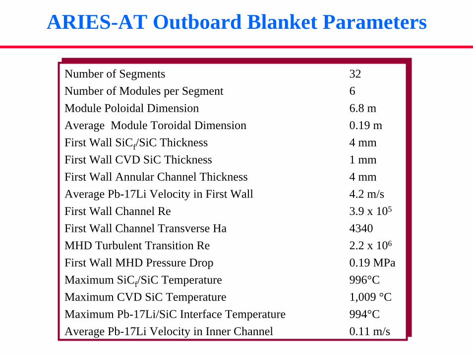
ARIES-AT Outboard Blanket Parameters
Number of Segments 32Number of Modules per Segment 6Module Poloidal Dimension 6.8 mAverage Module Toroidal Dimension 0.19 m First Wall SiCf/SiC Thickness 4 mmFirst Wall CVD SiC Thickness 1 mmFirst Wall Annular Channel Thickness 4 mmAverage Pb-17Li Velocity in First Wall 4.2 m/sFirst Wall Channel Re 3.9 x 10⁵
First Wall Channel Transverse Ha 4340MHD Turbulent Transition Re 2.2 x 10⁶
First Wall MHD Pressure Drop 0.19 MPaMaximum SiCf/SiC Temperature 996°CMaximum CVD SiC Temperature 1,009 °CMaximum Pb-17Li/SiC Interface Temperature 994°C Average Pb-17Li Velocity in Inner Channel 0.11 m/s
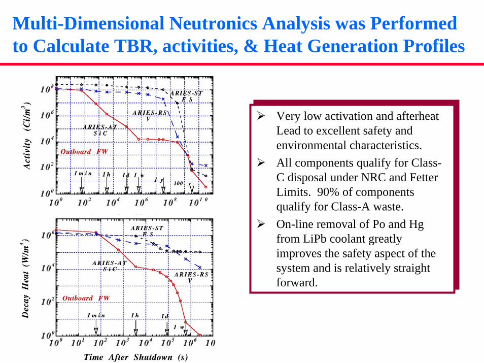
Multi-Dimensional Neutronics Analysis was Performed to Calculate TBR, activities, & Heat Generation Profiles
Very low activation and afterheat Lead to excellent safety and environmental characteristics.All components qualify for Class-C disposal under NRC and Fetter Limits. 90% of components qualify for Class-A waste.On-line removal of Po and Hg from LiPb coolant greatly improves the safety aspect of the system and is relatively straight forward.
Very low activation and afterheat Lead to excellent safety and environmental characteristics.All components qualify for Class-C disposal under NRC and Fetter Limits. 90% of components qualify for Class-A waste.On-line removal of Po and Hg from LiPb coolant greatly improves the safety aspect of the system and is relatively straight forward.
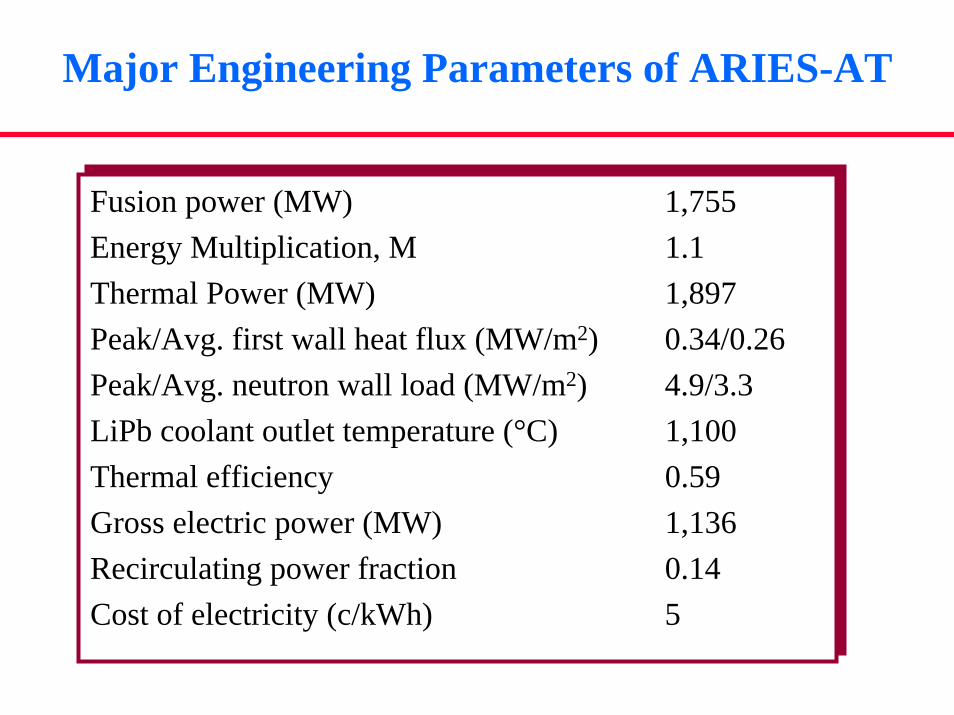
Major Engineering Parameters of ARIES-AT
Fusion power (MW) 1,755Energy Multiplication, M 1.1Thermal Power (MW) 1,897Peak/Avg. first wall heat flux (MW/m2) 0.34/0.26Peak/Avg. neutron wall load (MW/m2) 4.9/3.3LiPb coolant outlet temperature (°C) 1,100Thermal efficiency 0.59Gross electric power (MW) 1,136Recirculating power fraction 0.14Cost of electricity (c/kWh) 5
Fusion power (MW) 1,755Energy Multiplication, M 1.1Thermal Power (MW) 1,897Peak/Avg. first wall heat flux (MW/m2) 0.34/0.26Peak/Avg. neutron wall load (MW/m2) 4.9/3.3LiPb coolant outlet temperature (°C) 1,100Thermal efficiency 0.59Gross electric power (MW) 1,136Recirculating power fraction 0.14Cost of electricity (c/kWh) 5
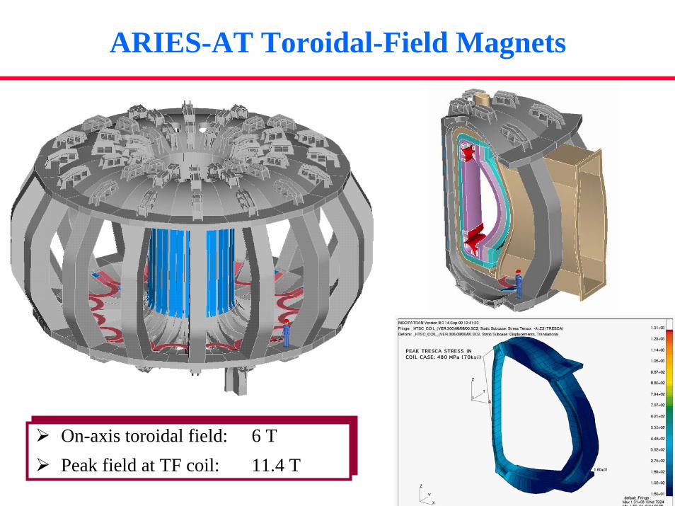
ARIES-AT Toroidal-Field Magnets
On-axis toroidal field: 6 TPeak field at TF coil: 11.4 T
On-axis toroidal field: 6 TPeak field at TF coil: 11.4 T
Use of High-Temperature Superconductors Simplifies the Magnet Systems
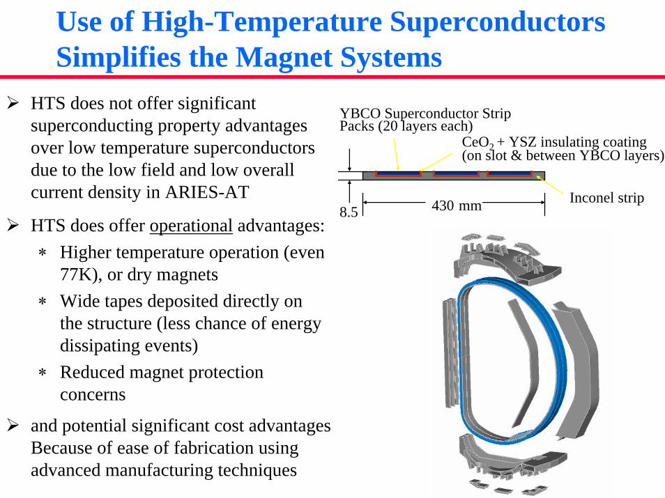
Inconel strip
YBCO Superconductor Strip Packs (20 layers each)
8.5 430 mm
CeO2 + YSZ insulating coating(on slot & between YBCO layers)
HTS does not offer significant superconducting property advantages over low temperature superconductors due to the low field and low overall current density in ARIES-AT
HTS does offer operational advantages:∗ Higher temperature operation (even
77K), or dry magnets∗ Wide tapes deposited directly on
the structure (less chance of energy dissipating events)
∗ Reduced magnet protection concerns
and potential significant cost advantagesBecause of ease of fabrication using advanced manufacturing techniques

ARIES-AT Uses a Full-sector Maintenance Scheme and a High Availability Is Predicted
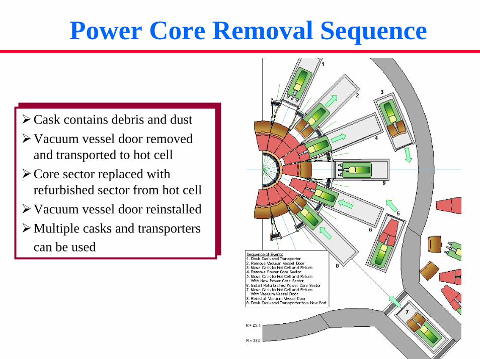
Power Core Removal Sequence
Cask contains debris and dustVacuum vessel door removed and transported to hot cellCore sector replaced with refurbished sector from hot cellVacuum vessel door reinstalledMultiple casks and transporters can be used
Cask contains debris and dustVacuum vessel door removed and transported to hot cellCore sector replaced with refurbished sector from hot cellVacuum vessel door reinstalledMultiple casks and transporters can be used
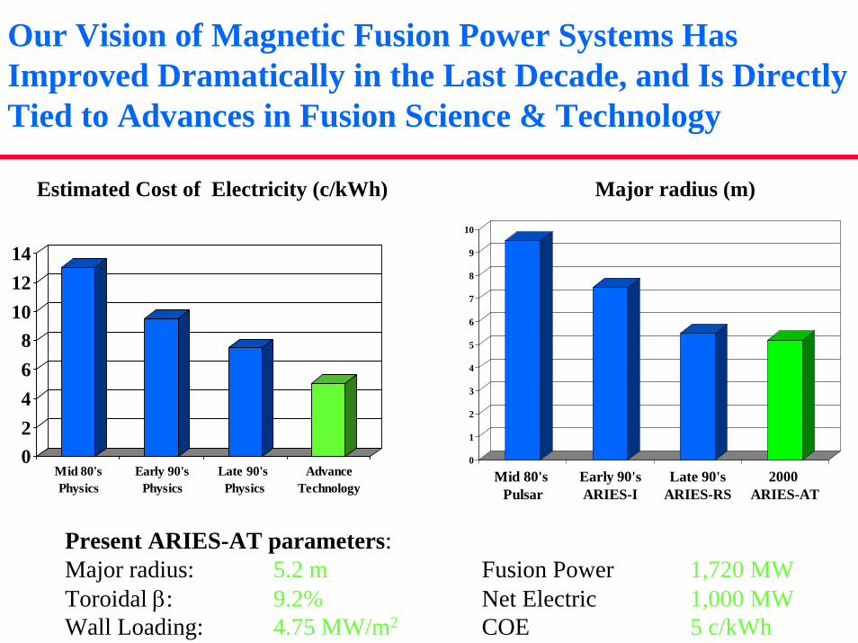
Our Vision of Magnetic Fusion Power Systems Has Improved Dramatically in the Last Decade, and Is Directly Tied to Advances in Fusion Science & Technology
Estimated Cost of Electricity (c/kWh)
02468
101214
Mid 80'sPhysics
Early 90'sPhysics
Late 90's Physics
AdvanceTechnology
Major radius (m)
0
1
2
3
4
5
6
7
8
9
10
Mid 80's Pulsar
Early 90'sARIES-I
Late 90'sARIES-RS
2000 ARIES-AT
Present ARIES-AT parameters:Major radius: 5.2 m Fusion Power 1,720 MWToroidal β: 9.2% Net Electric 1,000 MWWall Loading: 4.75 MW/m2 COE 5 c/kWh
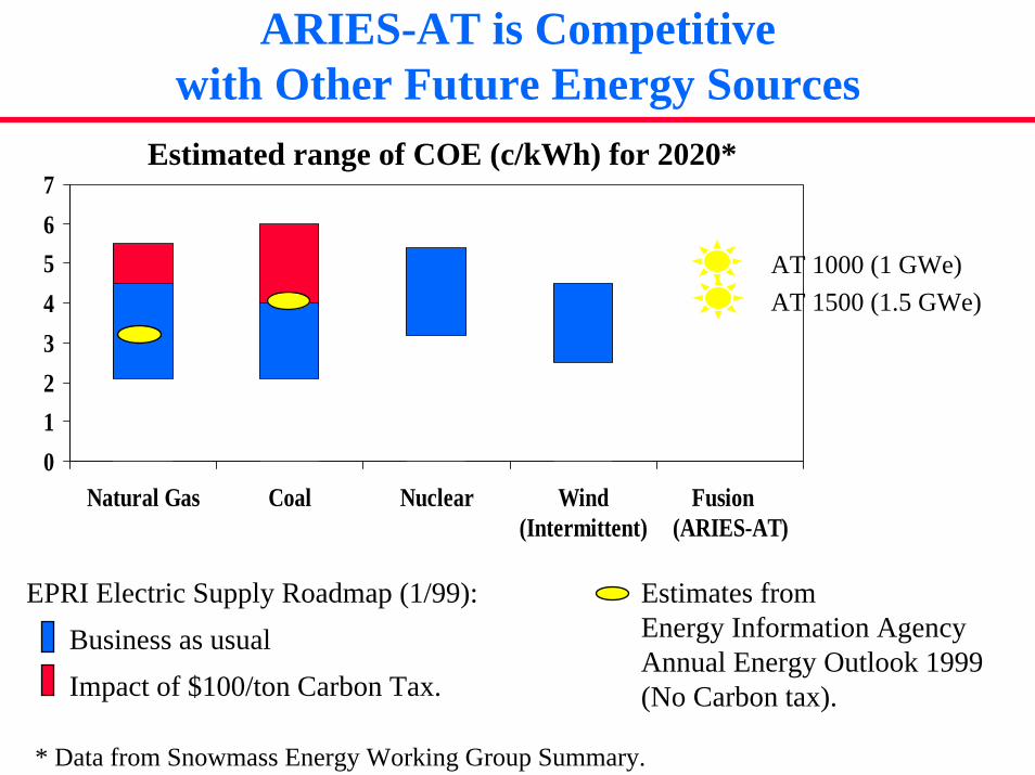
ARIES-AT is Competitive with Other Future Energy Sources
Estimated range of COE (c/kWh) for 2020*
01234567
Natural Gas Coal Nuclear Wind(Intermittent)
Fusion (ARIES-AT)
AT 1000 (1 GWe)AT 1500 (1.5 GWe)
EPRI Electric Supply Roadmap (1/99):Business as usualImpact of $100/ton Carbon Tax.
* Data from Snowmass Energy Working Group Summary.
Estimates from Energy Information AgencyAnnual Energy Outlook 1999(No Carbon tax).
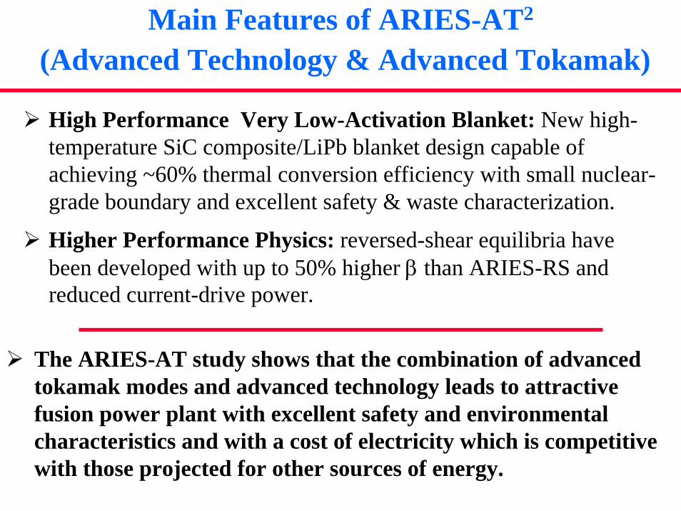
Main Features of ARIES-AT2
(Advanced Technology & Advanced Tokamak)
High Performance Very Low-Activation Blanket: New high-temperature SiC composite/LiPb blanket design capable of achieving ~60% thermal conversion efficiency with small nuclear-grade boundary and excellent safety & waste characterization.
Higher Performance Physics: reversed-shear equilibria have been developed with up to 50% higher β than ARIES-RS and reduced current-drive power.
The ARIES-AT study shows that the combination of advanced tokamak modes and advanced technology leads to attractive fusion power plant with excellent safety and environmental characteristics and with a cost of electricity which is competitive with those projected for other sources of energy.


![1 6/13/2015 ARIES PULSAR STARLITE Overview of ARIES Physics Studies ARIES-I, ARIES-II/IV, ARIES-III [D- 3 He], Pulsar, ARIES-RS, ARIES-ST, ARIES-AT presented](https://img.pdfslide.net/doc/110x75/56649d3e5503460f94a176ec/1-6132015-aries-pulsar-starlite-overview-of-aries-physics-studies-aries-i.jpg)