Embed Size (px)
Citation preview
ARM® DS-5™
Version 5.15
EB FVP Reference Guide
Copyright © 2008-2010, 2012-2013 ARM. All rights reserved.ARM DUI 0424J (ID061213)
ARM DS-5 EB FVP Reference Guide
Copyright © 2008-2010, 2012-2013 ARM. All rights reserved.
Release Information
Proprietary Notice
Words and logos marked with or are registered trademarks or trademarks of ARM in the EU and other countries, except as otherwise stated below in this proprietary notice. Other brands and names mentioned herein may be the trademarks of their respective owners.
Neither the whole nor any part of the information contained in, or the product described in, this document may be adapted or reproduced in any material form except with the prior written permission of the copyright holder.
The product described in this document is subject to continuous developments and improvements. All particulars of the product and its use contained in this document are given by ARM in good faith. However, all warranties implied or expressed, including but not limited to implied warranties of merchantability, or fitness for purpose, are excluded.
This document is intended only to assist the reader in the use of the product. ARM shall not be liable for any loss or damage arising from the use of any information in this document, or any error or omission in such information, or any incorrect use of the product.
Where the term ARM is used it means “ARM or any of its subsidiaries as appropriate”.
Confidentiality Status
This document is Non-Confidential. The right to use, copy and disclose this document may be subject to license restrictions in accordance with the terms of the agreement entered into by ARM and the party that ARM delivered this document to.
Product Status
The information in this document is final, that is for a developed product.
Web Address
http://www.arm.com
Change History
Date Issue Confidentiality Change
August 2008 A Non-Confidential Release for RealView Development Suite v4.0 Professional, System Generator v4.0 SP1.
December 2008 B Non-Confidential Release for Fast Models 4.1. Added changes related to ARM_RTSM_PATH.
March 2009 C Non-Confidential Release for Fast Models 4.2. Minor changes to text. Added description for device-accurate-tlb parameter.
November 2009 D Non-Confidential Release for models provided by RealView Development Suite v4.0 Professional edition.
May 2010 E Non-Confidential Release for models provided by RealView Development Suite v4.1 Professional edition.
September 2010 F Non-Confidential Release for models provided by RealView Development Suite v4.1 SP1 Professional edition.
October 2012 G Non-Confidential Release for DS-5 version 5.12.
December 2012 H Non-Confidential Release for DS-5 version 5.13.
March 2013 I Non-Confidential Release for DS-5 version 5.14.
June 2013 J Non-Confidential Release for DS-5 version 5.15.
ARM DUI 0424J Copyright © 2008-2010, 2012-2013 ARM. All rights reserved. iiID061213 Non-Confidential
ARM DUI 0424J Copyright © 2008-2010, 2012-2013 ARM. All rights reserved. iiiID061213 Non-Confidential
ContentsARM DS-5 EB FVP Reference Guide
PrefaceAbout this book ............................................................................................................ vFeedback .................................................................................................................. viii
Chapter 1 Introduction1.1 Introduction to system models ................................................................................. 1-21.2 Introduction to the EB FVP ...................................................................................... 1-3
Chapter 2 Getting Started with EB FVPs2.1 Starting an FVP ....................................................................................................... 2-22.2 Configuring an FVP ................................................................................................. 2-32.3 Using the CLCD window .......................................................................................... 2-52.4 Using Ethernet with an EB FVP ............................................................................... 2-82.5 Using a terminal with a system model ................................................................... 2-102.6 Virtual filesystem .................................................................................................... 2-122.7 Using the VFS with a pre-built FVP ....................................................................... 2-14
Chapter 3 Programmer’s Reference for the EB FVPs3.1 EB model memory map ........................................................................................... 3-23.2 EB model configuration parameters ........................................................................ 3-53.3 EB FVP baseboard parameters ............................................................................... 3-63.4 Ethernet parameters ................................................................................................ 3-93.5 System controller parameters ................................................................................ 3-103.6 UART parameters .................................................................................................. 3-113.7 Terminal parameters .............................................................................................. 3-123.8 Visualization parameters ....................................................................................... 3-133.9 FVP_EB_Cortex-A8 CoreTile parameters ............................................................. 3-143.10 Differences between the EB and CoreTile hardware and the models ................... 3-15

Preface
This preface introduces the EB FVP Reference Guide. It contains the following sections:• About this book on page v• Feedback on page viii.
ARM DUI 0424J Copyright © 2008-2010, 2012-2013 ARM. All rights reserved. ivID061213 Non-Confidential
Preface
About this bookThis book describes how to configure and use the Fixed Virtual Platforms (FVPs). The models let you run software applications on a virtual implementation of an Emulation Baseboard (EB) and an attached CoreTile.
The EB FVPs are models of ARM® application processors.
Intended audience
This book has been written for experienced hardware and software developers to:
• understand how the FVP examples are constructed
• use the FVPs as part of a development environment to aid the development of products that use ARM architecture-based processors or peripherals.
Using this book
This book is organized into the following chapters:
Chapter 1 Introduction Read this for an introduction to the general description of software models.
Chapter 2 Getting Started with EB FVPs Read this for a description of how to start using the EB FVPs. It also contains information on the terminal and Ethernet features provided with the EB FVPs.
Chapter 3 Programmer’s Reference for the EB FVPs Read this for a description of the EB memory map and registers, in addition to information on model parameters and component configuration. It also describes differences between the EB FVPs and their hardware equivalents.
Conventions
Conventions that this book can use are described in:• Conventions• Signals on page vi.
Typographical
The typographical conventions are:
italic Highlights important notes, introduces special terminology, denotes internal cross-references, and citations.
bold Highlights interface elements, such as menu names. Denotes signal names. Also used for terms in descriptive lists, where appropriate.
monospace Denotes text that you can enter at the keyboard, such as commands, file and program names, and source code.
monospace Denotes a permitted abbreviation for a command or option. You can enter the underlined text instead of the full command or option name.
monospace italic Denotes arguments to monospace text where the argument is to be replaced by a specific value.
ARM DUI 0424J Copyright © 2008-2010, 2012-2013 ARM. All rights reserved. vID061213 Non-Confidential
Preface
monospace bold Denotes language keywords when used outside example code.
< and > Enclose replaceable terms for assembler syntax where they appear in code or code fragments. For example:MRC p15, 0 <Rd>, <CRn>, <CRm>, <Opcode_2>
Signals
The signal conventions are:
Signal level The level of an asserted signal depends on whether the signal is active-HIGH or active-LOW. Asserted means:• HIGH for active-HIGH signals• LOW for active-LOW signals.
Lower-case n At the start or end of a signal name denotes an active-LOW signal.
Additional reading
This section lists publications by ARM and by third parties.
See Infocenter, http://infocenter.arm.com for access to ARM documentation.
ARM publications
This book contains information that is specific to this product. The following publications provide reference information about the ARM architecture:• AMBA® Specification (ARM IHI 0011)• ARM Architecture Reference Manual (ARM DDI 0100).
The following publications provide information about related ARM products and toolkits:• Component Architecture Debug Interface Developer Guide (ARM DUI 0444)• Fast Models Reference Manual (ARM DUI 0423)• Fast Models User Guide (ARM DUI 0370)• Model Shell for Fast Models Reference Manual (ARM DUI 0457).
The following publications provide information about ARM PrimeCell® and other peripheral or controller devices:
• ARM® PrimeCell® UART (PL011) Technical Reference Manual (ARM DDI 0183)
• ARM® PrimeCell® Synchronous Serial Port Controller (PL022) Technical Reference Manual (ARM DDI 0194)
• ARM® PrimeCell® Real-Time Clock Controller (PL031) Technical Reference Manual (ARM DDI 0224)
• ARM® PrimeCell® Advanced Audio CODEC Interface (PL041) Technical Reference Manual (ARM DDI 0173)
• ARM® PrimeCell® GPIO (PL061) Technical Reference Manual (ARM DDI 0190)
• ARM® PrimeCell® DMA (PL081) Technical Reference Manual (ARM DDI 0196)
• ARM® PrimeCell® Synchronous Static Memory Controller (PL093) Technical Reference Manual (ARM DDI 236)
ARM DUI 0424J Copyright © 2008-2010, 2012-2013 ARM. All rights reserved. viID061213 Non-Confidential

Preface
• ARM® PrimeCell® Color LCD Controller (PL111) Technical Reference Manual (ARM DDI 0161)
• ARM® PrimeCell® Smart Card Interface (PL131) Technical Reference Manual (ARM DDI 0228)
• ARM® PrimeCell® Multimedia Card Interface (PL180) Technical Reference Manual (ARM DDI 0172)
• ARM® PrimeCell® External Bus Interface (PL220) Technical Reference Manual (ARM DDI 0249)
• PrimeCell® Level 2 Cache Controller (PL310) Technical Reference Manual (ARM DDI 0246)
• ARM® Dynamic Memory Controller (PL340) Technical Reference Manual (ARM DDI 0331)
• PrimeCell® Generic Interrupt Controller (PL390) Technical Reference Manual (ARM DDI 0416)
• ARM® Dual-Timer Module (SP804) Technical Reference Manual (ARM DDI 0271)
• ARM® PrimeCell® Watchdog Controller (SP805) Technical Reference Manual (ARM DDI 0270)
• ARM® PrimeCell® System Controller (SP810) Technical Reference Manual (ARM DDI 0254).
Other publications
This section lists relevant documents published by third parties. The following data sheets describe some of the integrated circuits or modules used on the EB:
• CODEC with Sample Rate Conversion and 3D Sound (LM4549) National Semiconductor, Santa Clara, CA.
• MultiMedia Card Product Manual SanDisk, Sunnyvale, CA.
• Serially Programmable Clock Source (ICS307), ICS, San Jose, CA.
• 1.8 Volt Intel StrataFlash Wireless Memory with 3.0 Volt I/O (28F256L30B90) Intel Corporation, Santa Clara, CA.
• Three-In-One Fast Ethernet Controller (LAN91C111) SMSC, Hauppauge, NY.
ARM DUI 0424J Copyright © 2008-2010, 2012-2013 ARM. All rights reserved. viiID061213 Non-Confidential
Preface
FeedbackARM welcomes feedback on this product and its documentation.
Feedback on this product
If you have any comments or suggestions about this product, contact your supplier and give:
• The product name.
• The product revision or version.
• An explanation with as much information as you can provide. Include symptoms if appropriate.
Feedback on content
If you have any comments on content, send an e-mail to [email protected]. Give:• the title• the number, ARM DUI 0424J• the page numbers to which your comments apply• a concise explanation of your comments.
ARM also welcomes general suggestions for additions and improvements.
ARM DUI 0424J Copyright © 2008-2010, 2012-2013 ARM. All rights reserved. viiiID061213 Non-Confidential
Chapter 1 Introduction
This chapter introduces the Fixed Virtual Platforms. It contains the following sections: • Introduction to system models on page 1-2• Introduction to the EB FVP on page 1-3.
ARM DUI 0424J Copyright © 2008-2010, 2012-2013 ARM. All rights reserved. 1-1ID061213 Non-Confidential
Introduction
1.1 Introduction to system modelsThe Fixed Virtual Platforms (FVP) enable development of software without the requirement for actual hardware.
The software models provide Programmer’s View (PV) models of processors and devices. The functional behavior of a model is equivalent to real hardware.
Absolute timing accuracy is sacrificed to achieve fast simulated execution speed. This means that you can use the PV models for confirming software functionality, but you must not rely on the accuracy of cycle counts, low-level component interactions, or other hardware-specific behavior.
ARM DUI 0424J Copyright © 2008-2010, 2012-2013 ARM. All rights reserved. 1-2ID061213 Non-Confidential
Introduction
1.2 Introduction to the EB FVPThe EB and CoreTiles are hardware development platforms produced by ARM.
The EB FVPs are system models implemented in software. They are developed using the ARM® Fast Models™ library product.
Note The EB FVPs are provided as example platform implementations and are not intended to be accurate representations of a specific EB hardware revision. The FVPs support selected peripherals as described in this book. The supplied FVPs are sufficiently complete and accurate to boot the same operating system images as for EB hardware.
See also:• About the EB and CoreTile hardware• About the EB Fixed Virtual Platforms on page 1-4.
1.2.1 About the EB and CoreTile hardware
The major components on the hardware version of the baseboard are:
• two tile sites (supports ARM CoreTiles and LogicTiles)
• Field Programmable Gate-Array (FPGA) that implements a bus matrix, configuration interface, peripheral controllers, and interface logic
• 8MB configuration flash that holds FPGA images
• 256MB of 32-bit wide DDR SDRAM
• 4MB of 32-bit wide Cellular (Pseudo-static) RAM
• 64MB of 32-bit wide NOR flash
• up to 320MB (5x64MB) of static memory (flash or RAM) in an optional PISMO expansion board
• PCI expansion connector
• USB interface controller IC and connector
• Ethernet interface controller IC and connector
• connectors for VGA, color LCD display interface board, four UARTs, GPIO, keyboard, mouse, Smart Card, audio, MMC, and SSP
• electronic switches that select between the controllers located in the FPGA or on one of the tile sites
• debug and test connectors for JTAG, Integrated Logic Analyzer, and Trace port
• general purpose DIP switches and LEDs
• 2 row by 16 character LCD display
• power supply circuitry
• Real-Time Clock (RTC)
• time of year clock with backup battery
ARM DUI 0424J Copyright © 2008-2010, 2012-2013 ARM. All rights reserved. 1-3ID061213 Non-Confidential
Introduction
• programmable clock generators.
1.2.2 About the EB Fixed Virtual Platforms
The Fixed Virtual Platform components for the EB Reference System are:• Processor CoreTile:
— Cortex™-A8.• EB model with:
— 64MB Flash memory— 256MB RAM— Ethernet interface— UART interface — debug DIP switches and LEDs— Real-Time Clock (RTC)— time of year clock— programmable clock generators— Synchronous Serial Port Interface (SSPI)— DMA controller configuration registers— Static Memory Controller (SMC).
The EB FVP also includes virtual components:• visualization for Color LCD (CLCD) display, keyboard and mouse• touch screen controller• four telnet terminals.
The Fixed Virtual Platforms for the EB Reference System are hierarchical models that consist of:• the top-level view of the model• the EB model• the CoreTile model that is used by the system model.
The EB FVPs provide a functionally-accurate model for software execution. However, the model sacrifices timing accuracy to increase simulation speed. Key deviations from actual hardware are:• timing is approximate• buses are simplified.
Many components can be configured at instantiation time. See EB model configuration parameters on page 3-5.
For more detail on the differences, see Differences between the EB and CoreTile hardware and the models on page 3-15.
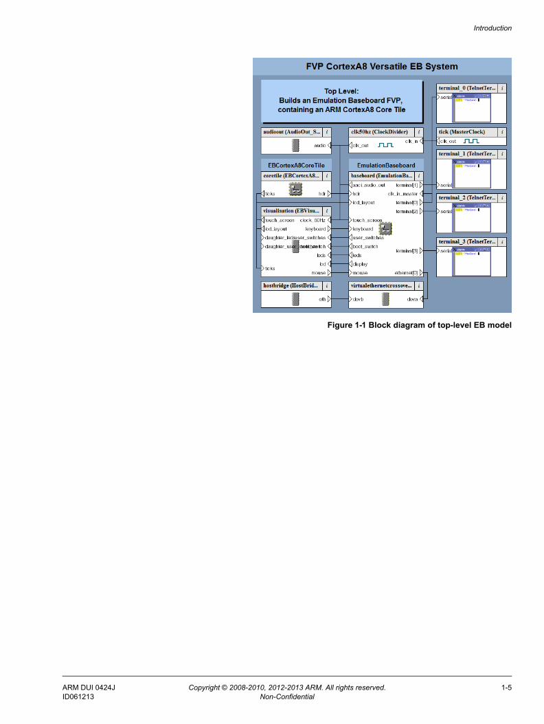
Top-level view of an EB model
A block diagram of the top-level model for an EB with a Cortex-A8 CoreTile is shown in Figure 1-1 on page 1-5.
ARM DUI 0424J Copyright © 2008-2010, 2012-2013 ARM. All rights reserved. 1-4ID061213 Non-Confidential
Introduction
Figure 1-1 Block diagram of top-level EB model
ARM DUI 0424J Copyright © 2008-2010, 2012-2013 ARM. All rights reserved. 1-5ID061213 Non-Confidential
Introduction
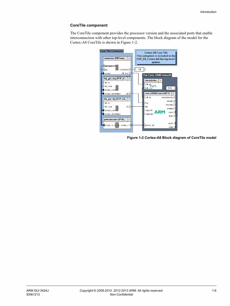
CoreTile component
The CoreTile component provides the processor version and the associated ports that enable interconnection with other top-level components. The block diagram of the model for the Cortex-A8 CoreTile is shown in Figure 1-2.
Figure 1-2 Cortex-A8 Block diagram of CoreTile model
ARM DUI 0424J Copyright © 2008-2010, 2012-2013 ARM. All rights reserved. 1-6ID061213 Non-Confidential
Introduction
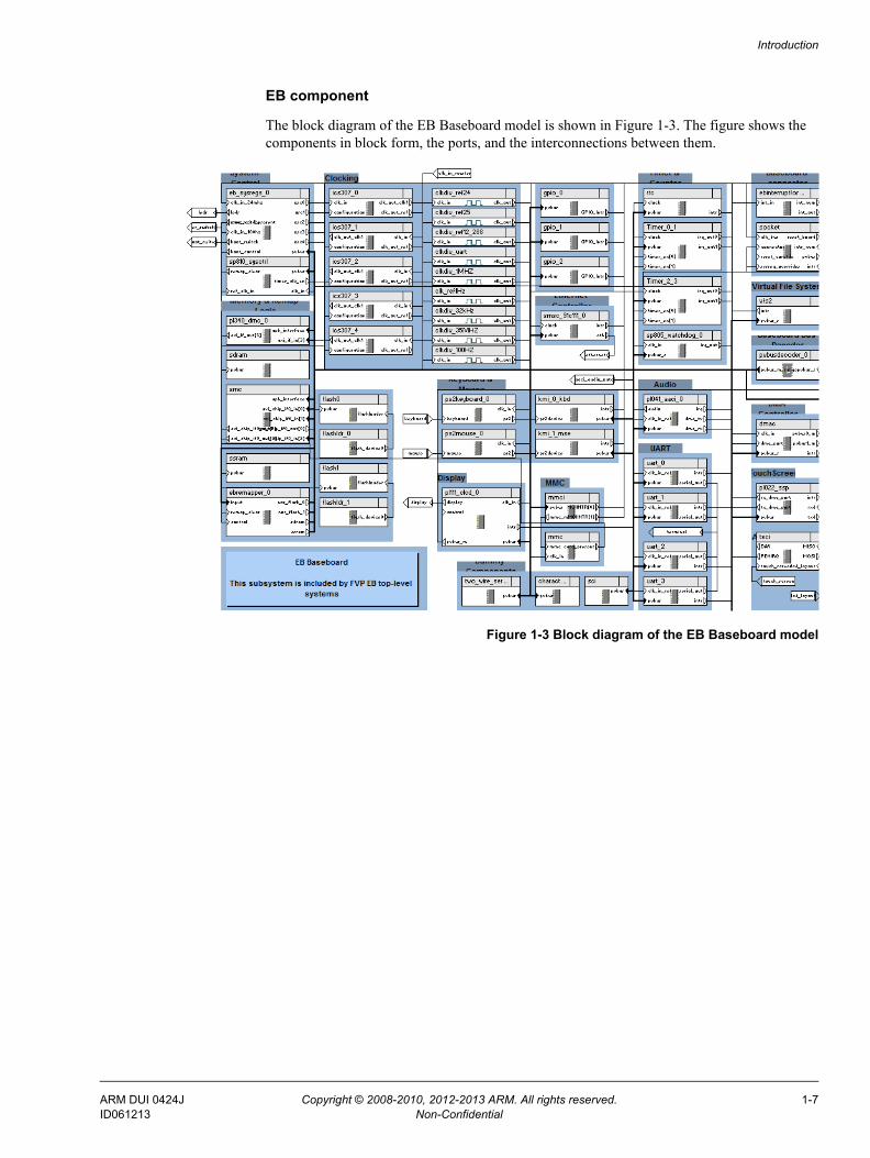
EB component
The block diagram of the EB Baseboard model is shown in Figure 1-3. The figure shows the components in block form, the ports, and the interconnections between them.
Figure 1-3 Block diagram of the EB Baseboard model
ARM DUI 0424J Copyright © 2008-2010, 2012-2013 ARM. All rights reserved. 1-7ID061213 Non-Confidential
Chapter 2 Getting Started with EB FVPs
This chapter describes the procedures for starting and configuring an EB FVP, and running a software application on the model. The procedures differ depending on the ARM software tools you are using. Read the sections that apply to the software you have. This chapter contains the following sections: • Starting an FVP on page 2-2• Configuring an FVP on page 2-3• Using the CLCD window on page 2-5• Using Ethernet with an EB FVP on page 2-8• Using a terminal with a system model on page 2-10• Virtual filesystem on page 2-12• Using the VFS with a pre-built FVP on page 2-14.
ARM DUI 0424J Copyright © 2008-2010, 2012-2013 ARM. All rights reserved. 2-1ID061213 Non-Confidential
Getting Started with EB FVPs
2.1 Starting an FVPThis section describes how to start an EB FVP. An example of loading and executing an application is documented separately.
The model can optionally start a CADI debug server allowing a CADI-enabled debugger, such as ARM DS-5™ Debugger, to be connected to the running model. It can also be configured to wait for a debugger connection before starting.
To start the FVP, change to the directory where your model file is and enter the following at the command prompt:
model_name [--cadi-server] [--config-file filename] [-C instance.parameter=value]
[--application app_filename]
where:
model_name is the name of the model file. By default this file name is typically FVP_EB_processor.
filename is the name of your optional plain-text configuration file. Configuration files simplify managing multiple parameters. See Using a configuration file on page 2-3.
instance.parameter=value is the optional direct setting of a configuration parameter. See Using the command line on page 2-3.
app_filename is the file name of an image to load to your model at startup.
For more information on model options, see the Model Shell for Fast Models Reference Manual.
Starting the model opens the FVP CLCD display. See Using the CLCD window on page 2-5.
After the FVP starts, you can use ARM DS-5 Debugger to connect to it.
ARM DUI 0424J Copyright © 2008-2010, 2012-2013 ARM. All rights reserved. 2-2ID061213 Non-Confidential
Getting Started with EB FVPs
2.2 Configuring an FVPThis section describes how to configure EB FVPs.
Valid user settings for the EB FVP parameters and their effects are described in EB model configuration parameters on page 3-5.
2.2.1 Setting model configuration options
The initial state of the FVP can be controlled by configuration settings provided on the command line or in the CADI properties for the model.
Using a configuration file
To configure a model that you start from the command line, include a reference to an optional plain text configuration file as described in Starting an FVP on page 2-2.
Comment lines in the configuration file must begin with a # character.
Each non-comment line of the configuration file contains:• the name of the component instance• the parameter to be modified and its value.
Boolean values can be set using either true/false or 1/0. Strings must be enclosed in double quotes if they contain whitespace.
A typical configuration file is listed in Example 2-1:
Example 2-1 Configuration file
# Disable semihosting using true/false syntaxcoretile.core.semihosting-enable=false## Enable the boot switch using 1/0 syntaxbaseboard.sp810_sysctrl.use_s8=1## Set the boot switch positionbaseboard.eb_sysregs_0.boot_switch_value=1
Using the command line
You can use the -C switch to define model parameters when you invoke the model. You can also use --parameter as a synonym for the -C switch. See Starting an FVP on page 2-2. Use the same syntax as for a configuration file, but each parameter must be preceded by the -C switch.
Examples
This section contains an example for configuring an EB FVP.
Example 2-2 shows how to set the boot options.
Example 2-2 Booting a model from a flash image
# Boot from a flash imageFVP_EB_Cortex-A8 \ --parameter "coretile.core.semihosting-cmd_line="\
ARM DUI 0424J Copyright © 2008-2010, 2012-2013 ARM. All rights reserved. 2-3ID061213 Non-Confidential
Getting Started with EB FVPs
--parameter "baseboard.flashldr_0.fname=flash.bin" \ --parameter "baseboard.eb_sysregs_0.user_switches_value=4" \ --parameter "visualisation.disable_visualisation=false" \ --parameter "visualisation.rate_limit-enable=0" \
ARM DUI 0424J Copyright © 2008-2010, 2012-2013 ARM. All rights reserved. 2-4ID061213 Non-Confidential
Getting Started with EB FVPs
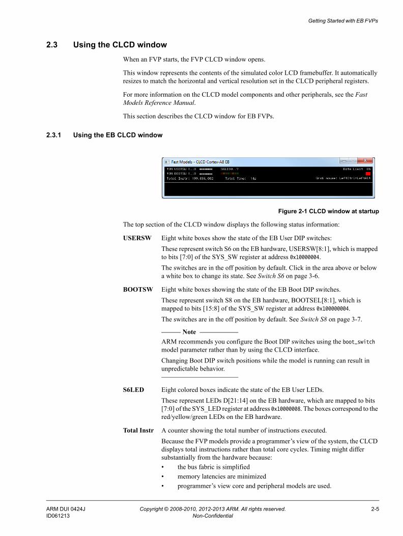
2.3 Using the CLCD windowWhen an FVP starts, the FVP CLCD window opens.
This window represents the contents of the simulated color LCD framebuffer. It automatically resizes to match the horizontal and vertical resolution set in the CLCD peripheral registers.
For more information on the CLCD model components and other peripherals, see the Fast Models Reference Manual.
This section describes the CLCD window for EB FVPs.
2.3.1 Using the EB CLCD window
Figure 2-1 CLCD window at startup
The top section of the CLCD window displays the following status information:
USERSW Eight white boxes show the state of the EB User DIP switches:These represent switch S6 on the EB hardware, USERSW[8:1], which is mapped to bits [7:0] of the SYS_SW register at address 0x10000004. The switches are in the off position by default. Click in the area above or below a white box to change its state. See Switch S6 on page 3-6.
BOOTSW Eight white boxes showing the state of the EB Boot DIP switches. These represent switch S8 on the EB hardware, BOOTSEL[8:1], which is mapped to bits [15:8] of the SYS_SW register at address 0x100000004. The switches are in the off position by default. See Switch S8 on page 3-7.
Note ARM recommends you configure the Boot DIP switches using the boot_switch
model parameter rather than by using the CLCD interface.Changing Boot DIP switch positions while the model is running can result in unpredictable behavior.
S6LED Eight colored boxes indicate the state of the EB User LEDs. These represent LEDs D[21:14] on the EB hardware, which are mapped to bits [7:0] of the SYS_LED register at address 0x10000008. The boxes correspond to the red/yellow/green LEDs on the EB hardware.
Total Instr A counter showing the total number of instructions executed.Because the FVP models provide a programmer’s view of the system, the CLCD displays total instructions rather than total core cycles. Timing might differ substantially from the hardware because:• the bus fabric is simplified• memory latencies are minimized• programmer’s view core and peripheral models are used.
ARM DUI 0424J Copyright © 2008-2010, 2012-2013 ARM. All rights reserved. 2-5ID061213 Non-Confidential
Getting Started with EB FVPs
In general, the timing of operations within a model is not accurate.
Total Time A counter showing the total elapsed time, in seconds. This is wall clock time, not simulated time.
Rate Limit A feature that prevents the simulation from running faster than wall clock time.Because the system model is highly optimized, your code might run faster than it would on real hardware. This might cause timing issues. Rate Limit is enabled by default. Simulation time is restricted so that it more closely matches real time. See Timing considerations on page 3-18. Click on the square button to disable or enable Rate Limit. The text changes from ON to OFF and the colored box becomes darker when Rate Limit is disabled.
Note You can control whether Rate Limit is enabled by using the rate_limit-enable
parameter when instantiating the model. See Visualization parameters on page 3-13.
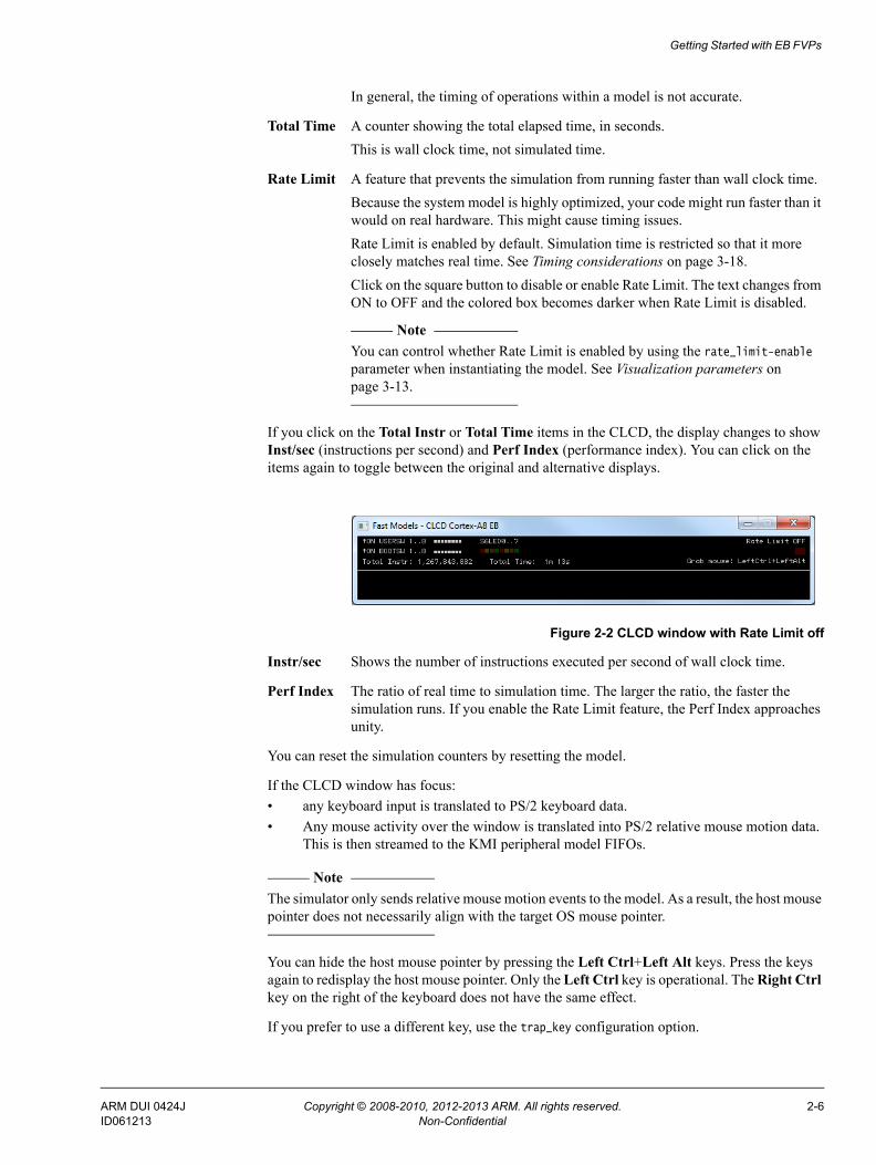
If you click on the Total Instr or Total Time items in the CLCD, the display changes to show Inst/sec (instructions per second) and Perf Index (performance index). You can click on the items again to toggle between the original and alternative displays.
Figure 2-2 CLCD window with Rate Limit off
Instr/sec Shows the number of instructions executed per second of wall clock time.
Perf Index The ratio of real time to simulation time. The larger the ratio, the faster the simulation runs. If you enable the Rate Limit feature, the Perf Index approaches unity.
You can reset the simulation counters by resetting the model.
If the CLCD window has focus:• any keyboard input is translated to PS/2 keyboard data. • Any mouse activity over the window is translated into PS/2 relative mouse motion data.
This is then streamed to the KMI peripheral model FIFOs.
Note The simulator only sends relative mouse motion events to the model. As a result, the host mouse pointer does not necessarily align with the target OS mouse pointer.
You can hide the host mouse pointer by pressing the Left Ctrl+Left Alt keys. Press the keys again to redisplay the host mouse pointer. Only the Left Ctrl key is operational. The Right Ctrl key on the right of the keyboard does not have the same effect.
If you prefer to use a different key, use the trap_key configuration option.
ARM DUI 0424J Copyright © 2008-2010, 2012-2013 ARM. All rights reserved. 2-6ID061213 Non-Confidential

Getting Started with EB FVPs
2.3.2 See also
Reference • Visualization parameters on page 3-13.
ARM DUI 0424J Copyright © 2008-2010, 2012-2013 ARM. All rights reserved. 2-7ID061213 Non-Confidential
Getting Started with EB FVPs
2.4 Using Ethernet with an EB FVPThe EB FVPs provide you with a virtual Ethernet component. This is a model of the SMSC91C111 Ethernet controller, and uses a TAP device to communicate with the network. By default, the Ethernet component is disabled.
2.4.1 Host requirements
Before you can use the Ethernet capability of the EB FVP, you must first set up your host computer. See the Fast Models User Guide for more information.
2.4.2 Target requirements
The EB FVPs include a software implementation of the SMSC91C111 device. Your target OS must therefore include a driver for this specific device, and you must configure the kernel to use the SMSC chip. Linux is the operating system that supports the SMSC91C111.
There are three Ethernet component parameters you can configure for the Ethernet component:• enabled• MAC address• promiscuous.
Configure these before starting the EB FVP.
enabled
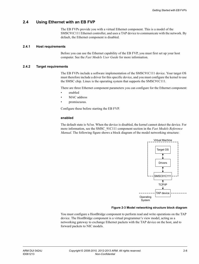
The default state is false. When the device is disabled, the kernel cannot detect the device. For more information, see the SMSC_91C111 component section in the Fast Models Reference Manual. The following figure shows a block diagram of the model networking structure:
Figure 2-3 Model networking structure block diagram
You must configure a HostBridge component to perform read and write operations on the TAP device. The HostBridge component is a virtual programmer’s view model, acting as a networking gateway to exchange Ethernet packets with the TAP device on the host, and to forward packets to NIC models.
Target OS
Drivers
SMSC91C111
TAP device
Virtual Machine
TCP/IP
Operating System
ARM DUI 0424J Copyright © 2008-2010, 2012-2013 ARM. All rights reserved. 2-8ID061213 Non-Confidential
Getting Started with EB FVPs
mac_address
There are two options for the mac_address parameter.
If you do not specify a MAC address, then when the simulator runs it takes the default MAC address. The address is randomly-generated to increase the chance of it being unique when running models on multiple hosts on a local network.
promiscuous
The default state is true. This means that it receives all network traffic, even any not specifically addressed to the device. You must use the default if you are using a single network device for multiple MAC addresses. Use it if, for example, you are sharing the same network card between your host OS and the EB FVP Ethernet component.
By default, the Ethernet device on the EB FVP has a randomly-generated MAC address.
2.4.3 Configuring Ethernet
For information on configuring a connection to the Ethernet interface on the FVP from Microsoft Windows or Linux, see the Fast Models User Guide.
2.4.4 See also
Reference • Fast Models Reference Manual,
http://infocenter.arm.com/help/topic/com.arm.doc.dui0423-/index.html
• Fast Models User Guide, http://infocenter.arm.com/help/topic/com.arm.doc.dui0370-/index.html.
ARM DUI 0424J Copyright © 2008-2010, 2012-2013 ARM. All rights reserved. 2-9ID061213 Non-Confidential
Getting Started with EB FVPs
2.5 Using a terminal with a system modelThe Terminal component is a virtual component that enables UART data to be transferred between a TCP/IP socket on the host and a serial port on the target.
Note To use the Terminal component with a Microsoft Windows 7 client, you must first install Telnet. The Telnet application is not installed on Microsoft Windows Vista by default.
Download the application by following the instructions on the Microsoft web site. Search for “Windows 7 Telnet” to find the Telnet FAQ page. To install Telnet:
1. Select Start → Control Panel → Programs and Features. This opens a window that enables you uninstall or change programs.
2. Select Turn Windows features on or off on the left side of the bar. This opens the Microsoft Windows Features dialog. Select the Telnet Client check box.
3. Click OK. The installation of Telnet might take several minutes to complete.
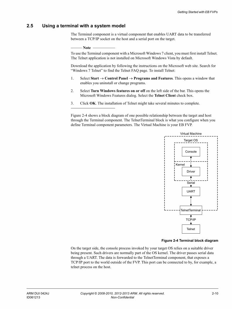
Figure 2-4 shows a block diagram of one possible relationship between the target and host through the Terminal component. The TelnetTerminal block is what you configure when you define Terminal component parameters. The Virtual Machine is your EB FVP.
Figure 2-4 Terminal block diagram
On the target side, the console process invoked by your target OS relies on a suitable driver being present. Such drivers are normally part of the OS kernel. The driver passes serial data through a UART. The data is forwarded to the TelnetTerminal component, that exposes a TCP/IP port to the world outside of the FVP. This port can be connected to by, for example, a telnet process on the host.
Console
Driver
UART
TelnetTerminal
Telnet
TCP/IP
Serial
Virtual Machine
Target OS
Kernel
ARM DUI 0424J Copyright © 2008-2010, 2012-2013 ARM. All rights reserved. 2-10ID061213 Non-Confidential
Getting Started with EB FVPs
By default, the EB FVP starts four telnet Terminals when the model is initialized. You can change the startup behavior for each of the four Terminals by modifying the corresponding component parameters.
If the Terminal connection is broken, for example by closing a client telnet session, the port is re-opened on the host. This might have a different port number if the original one is no longer available. Before the first data access, you can connect a client of your choice to the network socket. If there is no existing connection when the first data access is made, and the start_telnet parameter is true, a host telnet session is started automatically.
The port number of a particular Terminal instance can be defined when the FVP starts. The actual value of the port used by each Terminal is declared when it starts or restarts, and might not be the value you specified if the port is already in use. The port numbers are displayed in the host window in which you started the model.
You can start the Terminal component in either telnet mode or raw mode.
2.5.1 Telnet mode
In telnet mode, the Terminal component supports a subset of the RFC 854 protocol. This means that the Terminal participates in negotiations between the host and client concerning what is and is not supported, but flow control is not implemented.
2.5.2 Raw mode
Raw mode enables the byte stream to pass unmodified between the host and the target. This means that the Terminal component does not participate in initial capability negotiations between the host and client. It acts as a TCP/IP port. You can use this feature to directly connect to your target through the Terminal component.
ARM DUI 0424J Copyright © 2008-2010, 2012-2013 ARM. All rights reserved. 2-11ID061213 Non-Confidential
Getting Started with EB FVPs
2.6 Virtual filesystemThe Virtual FileSystem (VFS) allows your target to access parts of a host filesystem. This access is achieved through a target OS-specific driver and a memory mapped device called the MessageBox. When using the VFS, access to the host filesystem is analogous to access to a shared network drive, and can be expected to behave in the same way.
If you want to build your own system that includes the VFS, see the Fast Models Reference Manual. See also the WritingADriver.txt file in %PVLIB_HOME%\VFS\docs\.
The VFS supports the following filesystem operations:getattr retrieves metadata for the file, directory or symbolic linkmkdir creates a new directoryremove removes a file, directory or symbolic linkrename renames a file, directory or symbolic linkrmdir removes an empty directorysetattr sets metadata for the file, directory or symbolic link.
Note setattr is not implemented.
Symbolic links are not supported. Hard links cannot be created by the model but hard links created by the host operating system function correctly.
The VFS supports the following mount points:closemounts
frees the iterator handle returned from openmountsopenmounts
retrieves an iterator handle for the list of available mountsreadmounts reads one entry from the mount iterator ID.
The VFS supports the following directory iterators:closedir frees a directory iterator handle retrieved by opendiropendir retrieves an iterator handle for the directory specifiedreaddir reads the next entry from the directory iterator.
Note Datestamps returned are in milliseconds elapsed since the VFS epoch of January 01 1970 00:00 UTC and are host datestamps. The host datestamp might be in the future relative to the simulated OS datestamp.
The VFS supports the following file operations:
closefile frees a handle opened with openfile
filesync forces the host OS to flush all file data to persistent storage
getfilesize returns the size of a file, in bytes
openfile returns a handle to the file specified
readfile reads a block of data from a file
setfilesize sets the size of a file in bytes, either by truncating, or extending the file with zeroes
ARM DUI 0424J Copyright © 2008-2010, 2012-2013 ARM. All rights reserved. 2-12ID061213 Non-Confidential

Getting Started with EB FVPs
writefile writes a block of data to a file.
2.6.1 See also
Reference • Using the VFS with a pre-built FVP on page 2-14• Fast Models Reference Manual,
http://infocenter.arm.com/help/topic/com.arm.doc.dui0423-/index.html.
ARM DUI 0424J Copyright © 2008-2010, 2012-2013 ARM. All rights reserved. 2-13ID061213 Non-Confidential
Getting Started with EB FVPs
2.7 Using the VFS with a pre-built FVPThe supplied EB FVPs include the necessary VFS components. This permits you to run a Linux image, for example, on the EB FVP and access the filesystem running on your computer.
To use the VFS functionality of the EB FVP, use the motherboard.vfs2.mount configuration parameter when you start the model. The value of the parameter is the path to the host filesystem directory that is to be made accessible within the model.
2.7.1 Mount names
When the target OS is running, create a mount point, such as /mnt/host. For example, on a Linux target, use the mount command as follows:
mount -t vmfs A /mnt/host
You can then access the host filesystem from the target OS through a supported filesystem operation. See the ReadMe.txt file in the %PVLIB_HOME%\VFS2\linux\ directory.
2.7.2 Path names
All path names must be fully qualified paths of the form:
mountpoint:/path/to/object
2.7.3 See also
Reference • Virtual filesystem on page 2-12• Fast Models Reference Manual,
http://infocenter.arm.com/help/topic/com.arm.doc.dui0423-/index.html.
ARM DUI 0424J Copyright © 2008-2010, 2012-2013 ARM. All rights reserved. 2-14ID061213 Non-Confidential
Chapter 3 Programmer’s Reference for the EB FVPs
This chapter describes the memory map and the configuration registers for the peripheral and system component models:• EB model memory map on page 3-2• EB model configuration parameters on page 3-5• EB FVP baseboard parameters on page 3-6• Ethernet parameters on page 3-9• UART parameters on page 3-11• Terminal parameters on page 3-12• Visualization parameters on page 3-13• FVP_EB_Cortex-A8 CoreTile parameters on page 3-14• Differences between the EB and CoreTile hardware and the models on page 3-15.
Note For detailed information on the programming interface for ARM PrimeCell® peripherals and controllers, see the appropriate technical reference manual.
ARM DUI 0424J Copyright © 2008-2010, 2012-2013 ARM. All rights reserved. 3-1ID061213 Non-Confidential
Programmer’s Reference for the EB FVPs
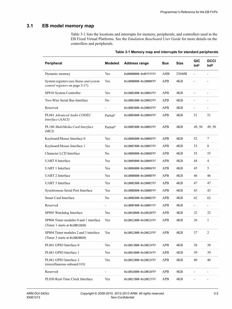
3.1 EB model memory mapTable 3-1 lists the locations and interrupts for memory, peripherals, and controllers used in the EB Fixed Virtual Platforms. See the Emulation Baseboard User Guide for more details on the controllers and peripherals.
Table 3-1 Memory map and interrupts for standard peripherals
Peripheral Modeled Address range Bus Size GIC Inta
DCCIIntb
Dynamic memory Yes 0x00000000–0x0FFFFFFF AHB 256MB - -
System registers (see Status and system control registers on page 3-17)
Yes 0x10000000–0x10000FFF APB 4KB - -
SP810 System Controller Yes 0x10001000–0x10001FFF APB 4KB - -
Two-Wire Serial Bus Interface No 0x10002000–0x10002FFF APB 4KB - -
Reserved - 0x10003000–0x10003FFF APB 4KB - -
PL041 Advanced Audio CODEC Interface (AACI)
Partialc 0x10004000–0x10004FFF APB 4KB 51 51
PL180 MultiMedia Card Interface (MCI)
Partiald 0x10005000–0x10005FFF APB 4KB 49, 50 49, 50
Keyboard/Mouse Interface 0 Yes 0x10006000–0x10006FFF APB 4KB 52 7
Keyboard/Mouse Interface 1 Yes 0x10007000–0x10007FFF APB 4KB 53 8
Character LCD Interface No 0x10008000–0x10008FFF APB 4KB 55 55
UART 0 Interface Yes 0x10009000–0x10009FFF APB 4KB 44 4
UART 1 Interface Yes 0x1000A000–0x1000AFFF APB 4KB 45 5
UART 2 Interface Yes 0x1000B000–0x1000BFFF APB 4KB 46 46
UART 3 Interface Yes 0x1000C000–0x1000CFFF APB 4KB 47 47
Synchronous Serial Port Interface Yes 0x1000D000–0x1000DFFF APB 4KB 43 43
Smart Card Interface No 0x1000E000–0x1000EFFF APB 4KB 62 62
Reserved - 0x1000F000–0x1000FFFF APB 4KB - -
SP805 Watchdog Interface Yes 0x10010000–0x10010FFF APB 4KB 32 32
SP804 Timer modules 0 and 1 interface(Timer 1 starts at 0x10011020)
Yes 0x10011000–0x10011FFF APB 4KB 36 1
SP804 Timer modules 2 and 3 interface (Timer 3 starts at 0x10020020)
Yes 0x10012000–0x10012FFF APB 4KB 37 2
PL061 GPIO Interface 0 Yes 0x10013000–0x10013FFF APB 4KB 38 38
PL061 GPIO Interface 1 Yes 0x10014000–0x10014FFF APB 4KB 39 39
PL061 GPIO Interface 2 (miscellaneous onboard I/O)
Yes 0x10015000–0x10015FFF APB 4KB 40 40
Reserved - 0x10016000–0x10016FFF APB 4KB - -
PL030 Real-Time Clock Interface Yes 0x10017000–0x10017FFF APB 4KB - -
ARM DUI 0424J Copyright © 2008-2010, 2012-2013 ARM. All rights reserved. 3-2ID061213 Non-Confidential
Programmer’s Reference for the EB FVPs
Dynamic Memory Controller configuration
Partiale 0x10018000–0x10018FFF APB 4KB - -
PCI controller configuration registers No 0x10019000–0x10019FFF AHB 4KB - -
Reserved - 0x1001A000–0x1001FFFF APB 24KB - -
PL111 Color LCD Controller Yes 0x10020000–0x1002FFFF AHB 64KB 55 55
DMA Controller configuration registers Yes 0x10030000–0x1003FFFF AHB 64KB - -
Generic Interrupt Controller 1CPU interface
Yesb 0x10040000–0x10040FFF AHB 4KB - -
Generic Interrupt Controller 1Distributor interface
Yes 0x10041000–0x10041FFF AHB 4KB - -
Generic Interrupt Controller 2 CPU interface (nFIQ for tile 1)
Nof 0x10050000–0x10050FFF AHB 4KB - -
Generic Interrupt Controller 2Distributor interface
Yes 0x10051000–0x10051FFF AHB 4KB - -
Generic Interrupt Controller 3 CPU interface (nIRQ for tile 2)
Nof 0x10060000–0x10060FFF AHB 4KB - -
Generic Interrupt Controller 3 Distributor interface
No 0x10061000–0x10061FFF AHB 4KB - -
Generic Interrupt Controller 4 CPU interface (nFIQ for tile 2)
Nof 0x10070000–0x10070FFF AHB 4KB - -
Generic Interrupt Controller 4 Distributor interface
No 0x10071000–0x10071FFF AHB 4KB - -
PL350 Static Memory Controller configurationg
Yes 0x10080000–0x1008FFFF AHB 64KB - -
Reserved - 0x10090000–0x100EFFFF AHB 448MB - -
Debug Access Port (DAP) ROM table. Some debuggers read information on the target processor and the debug chain from the DAP table.
No 0x100F0000–0x100FFFFF AHB 64KB - -
Reserved - 0x10100000–0x1FFFFFFF - 255MB - -
Reserved - 0x20000000–0x3FFFFFFF - 512MB - -
NOR Flash Yesh 0x40000000–0x43FFFFFF AXI 64MB - -
Disk on Chip No 0x44000000–0x47FFFFFF AXI 64MB 41 41
SRAM Yes 0x48000000–0x4BFFFFFF AXI 64MB - -
Configuration flash No 0x4C000000–0x4DFFFFFF AXI 32MB - -
Ethernet Yesi 0x4E000000–0x4EFFFFFF AXI 16MB 60 60
USB No 0x4F000000–0x4FFFFFFF AXI 16MB - -
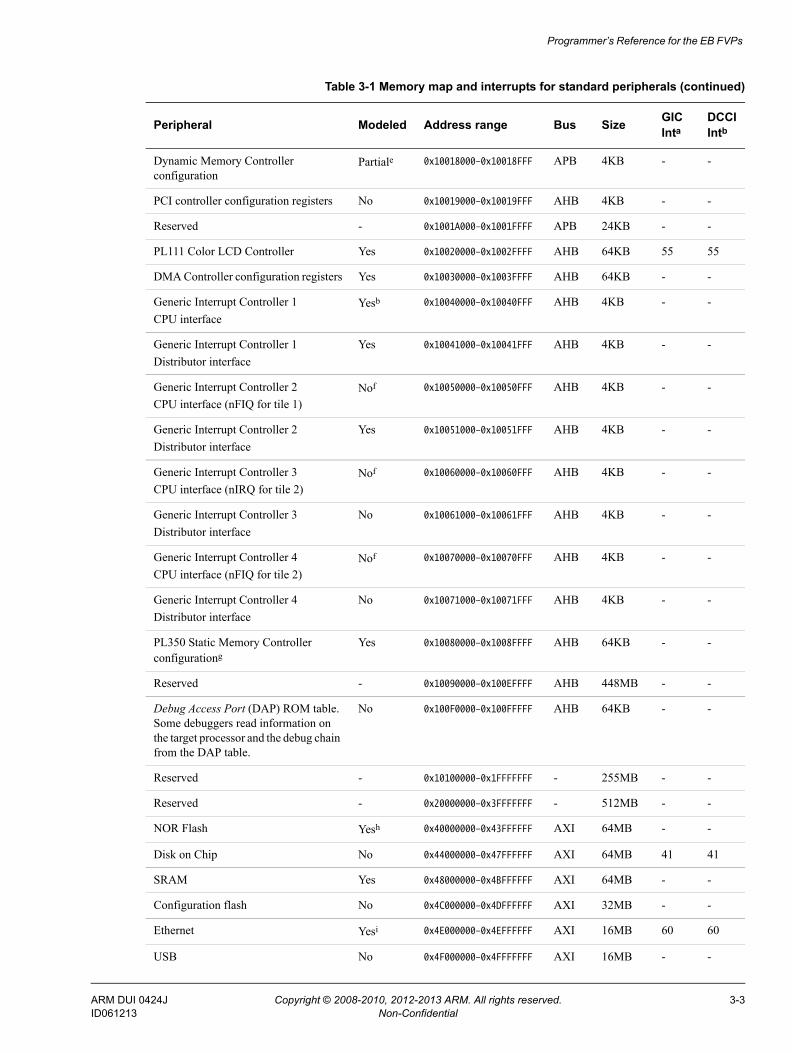
Table 3-1 Memory map and interrupts for standard peripherals (continued)
Peripheral Modeled Address range Bus Size GIC Inta
DCCIIntb
ARM DUI 0424J Copyright © 2008-2010, 2012-2013 ARM. All rights reserved. 3-3ID061213 Non-Confidential
Programmer’s Reference for the EB FVPs
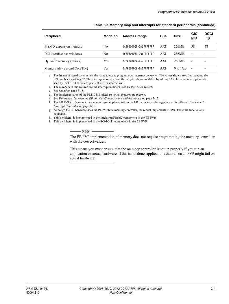
Note The EB FVP implementation of memory does not require programming the memory controller with the correct values.
This means you must ensure that the memory controller is set up properly if you run an application on actual hardware. If this is not done, applications that run on an FVP might fail on actual hardware.
PISMO expansion memory No 0x50000000–0x5FFFFFFF AXI 256MB 58 58
PCI interface bus windows No 0x60000000–0x6FFFFFFF AXI 256MB - -
Dynamic memory (mirror) Yes 0x70000000–0x7FFFFFFF AXI 256MB - -
Memory tile (Second CoreTile) Yes 0x70000000–0x7FFFFFFF AXI 0 to 1GB - -
a. The Interrupt signal column lists the value to use to program your interrupt controller. The values shown are after mapping the SPI number by adding 32. The interrupt numbers from the peripherals are modified by adding 32 to form the interrupt number seen by the GIC. GIC interrupts 0-31 are for internal use.
b. The numbers in this column are the interrupt numbers used by the DCCI system.c. See Sound on page 3-15.d. The implementation of the PL180 is limited, so not all features are present.e. See Differences between the EB and CoreTile hardware and the models on page 3-15.f. The EB FVP GICs are not the same as those implemented on the EB hardware as the register map is different. See Generic
Interrupt Controller on page 3-18.g. Although the EB hardware uses the PL093 static memory controller, the model implements PL350. These are functionally
equivalent.h. This peripheral is implemented in the IntelStrataFlashJ3 component in the EB FVP.i. This peripheral is implemented in the SC91C111 component in the EB FVP.
Table 3-1 Memory map and interrupts for standard peripherals (continued)
Peripheral Modeled Address range Bus Size GIC Inta
DCCIIntb
ARM DUI 0424J Copyright © 2008-2010, 2012-2013 ARM. All rights reserved. 3-4ID061213 Non-Confidential
Programmer’s Reference for the EB FVPs
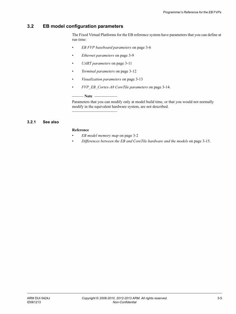
3.2 EB model configuration parametersThe Fixed Virtual Platforms for the EB reference system have parameters that you can define at run time:
• EB FVP baseboard parameters on page 3-6
• Ethernet parameters on page 3-9
• UART parameters on page 3-11
• Terminal parameters on page 3-12
• Visualization parameters on page 3-13
• FVP_EB_Cortex-A8 CoreTile parameters on page 3-14.
Note Parameters that you can modify only at model build time, or that you would not normally modify in the equivalent hardware system, are not described.
3.2.1 See also
Reference • EB model memory map on page 3-2• Differences between the EB and CoreTile hardware and the models on page 3-15.
ARM DUI 0424J Copyright © 2008-2010, 2012-2013 ARM. All rights reserved. 3-5ID061213 Non-Confidential
Programmer’s Reference for the EB FVPs
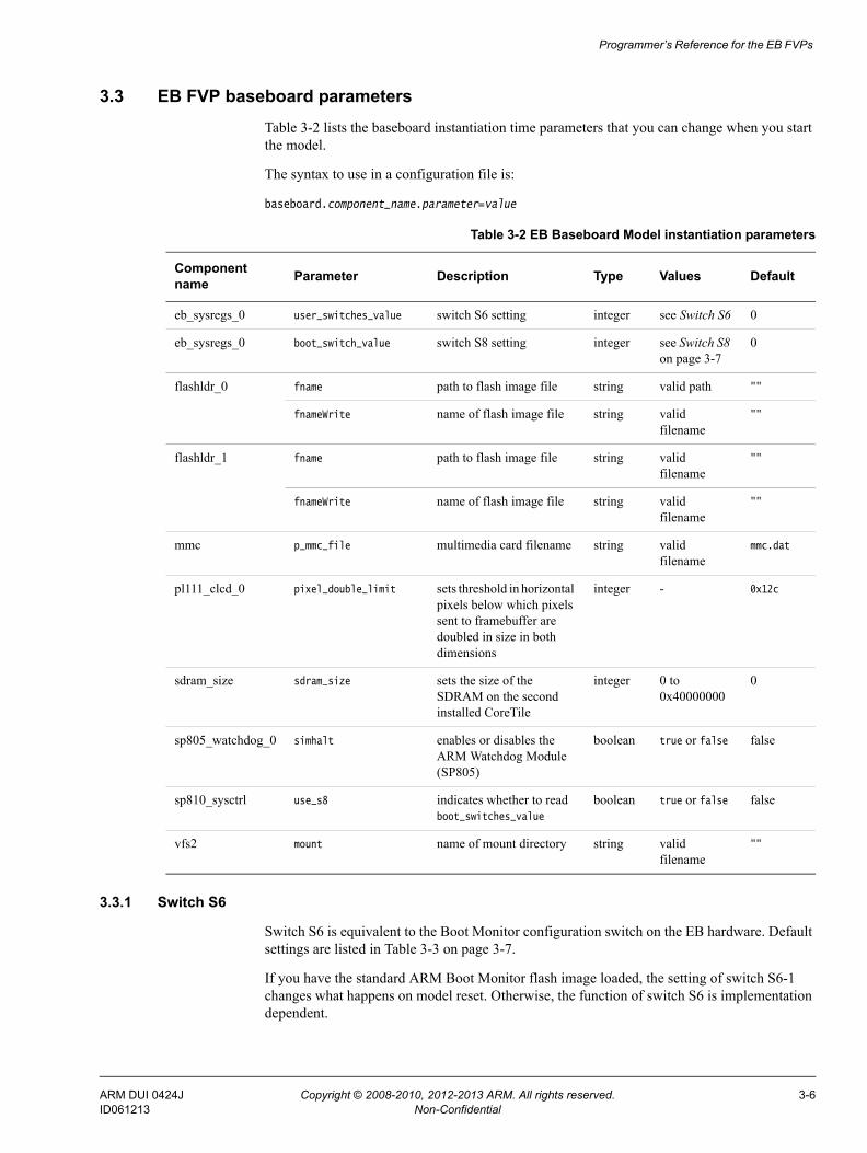
3.3 EB FVP baseboard parametersTable 3-2 lists the baseboard instantiation time parameters that you can change when you start the model.
The syntax to use in a configuration file is:
baseboard.component_name.parameter=value
3.3.1 Switch S6
Switch S6 is equivalent to the Boot Monitor configuration switch on the EB hardware. Default settings are listed in Table 3-3 on page 3-7.
If you have the standard ARM Boot Monitor flash image loaded, the setting of switch S6-1 changes what happens on model reset. Otherwise, the function of switch S6 is implementation dependent.
Table 3-2 EB Baseboard Model instantiation parameters
Component name Parameter Description Type Values Default
eb_sysregs_0 user_switches_value switch S6 setting integer see Switch S6 0
eb_sysregs_0 boot_switch_value switch S8 setting integer see Switch S8 on page 3-7
0
flashldr_0 fname path to flash image file string valid path ""
fnameWrite name of flash image file string valid filename
""
flashldr_1 fname path to flash image file string valid filename
""
fnameWrite name of flash image file string valid filename
""
mmc p_mmc_file multimedia card filename string valid filename
mmc.dat
pl111_clcd_0 pixel_double_limit sets threshold in horizontal pixels below which pixels sent to framebuffer are doubled in size in both dimensions
integer - 0x12c
sdram_size sdram_size sets the size of the SDRAM on the second installed CoreTile
integer 0 to 0x40000000
0
sp805_watchdog_0 simhalt enables or disables the ARM Watchdog Module (SP805)
boolean true or false false
sp810_sysctrl use_s8 indicates whether to read boot_switches_value
boolean true or false false
vfs2 mount name of mount directory string valid filename
""
ARM DUI 0424J Copyright © 2008-2010, 2012-2013 ARM. All rights reserved. 3-6ID061213 Non-Confidential
Programmer’s Reference for the EB FVPs
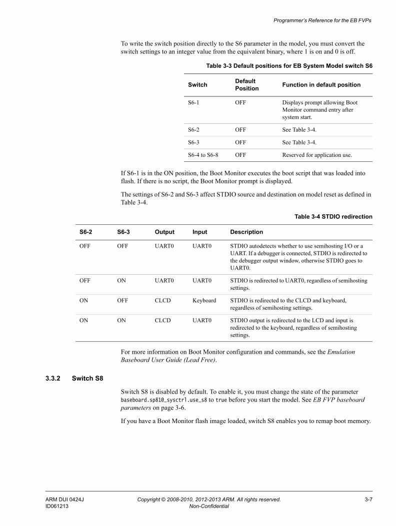
To write the switch position directly to the S6 parameter in the model, you must convert the switch settings to an integer value from the equivalent binary, where 1 is on and 0 is off.
If S6-1 is in the ON position, the Boot Monitor executes the boot script that was loaded into flash. If there is no script, the Boot Monitor prompt is displayed.
The settings of S6-2 and S6-3 affect STDIO source and destination on model reset as defined in Table 3-4.
For more information on Boot Monitor configuration and commands, see the Emulation Baseboard User Guide (Lead Free).
3.3.2 Switch S8
Switch S8 is disabled by default. To enable it, you must change the state of the parameter baseboard.sp810_sysctrl.use_s8 to true before you start the model. See EB FVP baseboard parameters on page 3-6.
If you have a Boot Monitor flash image loaded, switch S8 enables you to remap boot memory.
Table 3-3 Default positions for EB System Model switch S6
Switch Default Position Function in default position
S6-1 OFF Displays prompt allowing Boot Monitor command entry after system start.
S6-2 OFF See Table 3-4.
S6-3 OFF See Table 3-4.
S6-4 to S6-8 OFF Reserved for application use.
Table 3-4 STDIO redirection
S6-2 S6-3 Output Input Description
OFF OFF UART0 UART0 STDIO autodetects whether to use semihosting I/O or a UART. If a debugger is connected, STDIO is redirected to the debugger output window, otherwise STDIO goes to UART0.
OFF ON UART0 UART0 STDIO is redirected to UART0, regardless of semihosting settings.
ON OFF CLCD Keyboard STDIO is redirected to the CLCD and keyboard, regardless of semihosting settings.
ON ON CLCD UART0 STDIO output is redirected to the LCD and input is redirected to the keyboard, regardless of semihosting settings.
ARM DUI 0424J Copyright © 2008-2010, 2012-2013 ARM. All rights reserved. 3-7ID061213 Non-Confidential
Programmer’s Reference for the EB FVPs
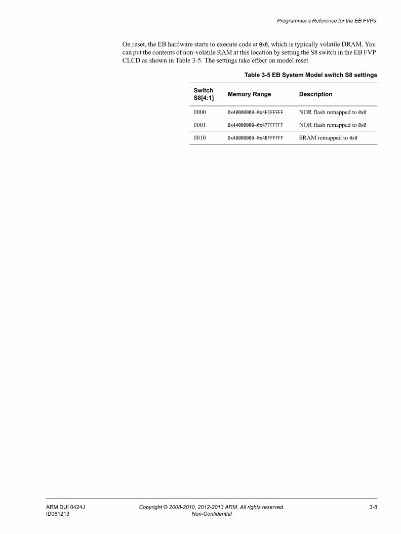
On reset, the EB hardware starts to execute code at 0x0, which is typically volatile DRAM. You can put the contents of non-volatile RAM at this location by setting the S8 switch in the EB FVP CLCD as shown in Table 3-5. The settings take effect on model reset.
Table 3-5 EB System Model switch S8 settings
Switch S8[4:1] Memory Range Description
0000 0x40000000–0x4FEFFFFF NOR flash remapped to 0x0
0001 0x44000000–0x47FFFFFF NOR flash remapped to 0x0
0010 0x48000000–0x4BFFFFFF SRAM remapped to 0x0
ARM DUI 0424J Copyright © 2008-2010, 2012-2013 ARM. All rights reserved. 3-8ID061213 Non-Confidential
Programmer’s Reference for the EB FVPs
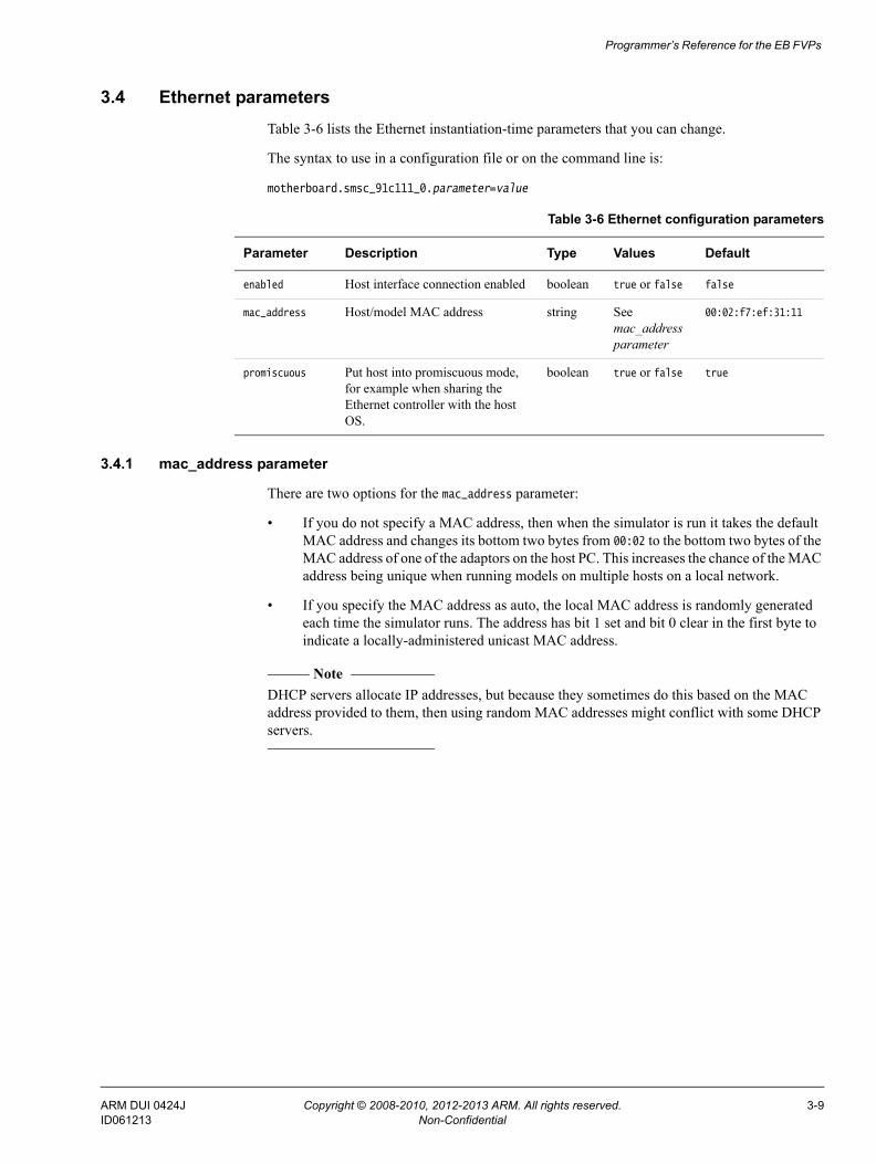
3.4 Ethernet parametersTable 3-6 lists the Ethernet instantiation-time parameters that you can change.
The syntax to use in a configuration file or on the command line is:
motherboard.smsc_91c111_0.parameter=value
3.4.1 mac_address parameter
There are two options for the mac_address parameter:
• If you do not specify a MAC address, then when the simulator is run it takes the default MAC address and changes its bottom two bytes from 00:02 to the bottom two bytes of the MAC address of one of the adaptors on the host PC. This increases the chance of the MAC address being unique when running models on multiple hosts on a local network.
• If you specify the MAC address as auto, the local MAC address is randomly generated each time the simulator runs. The address has bit 1 set and bit 0 clear in the first byte to indicate a locally-administered unicast MAC address.
Note DHCP servers allocate IP addresses, but because they sometimes do this based on the MAC address provided to them, then using random MAC addresses might conflict with some DHCP servers.
Table 3-6 Ethernet configuration parameters
Parameter Description Type Values Default
enabled Host interface connection enabled boolean true or false false
mac_address Host/model MAC address string See mac_address parameter
00:02:f7:ef:31:11
promiscuous Put host into promiscuous mode, for example when sharing the Ethernet controller with the host OS.
boolean true or false true
ARM DUI 0424J Copyright © 2008-2010, 2012-2013 ARM. All rights reserved. 3-9ID061213 Non-Confidential
Programmer’s Reference for the EB FVPs
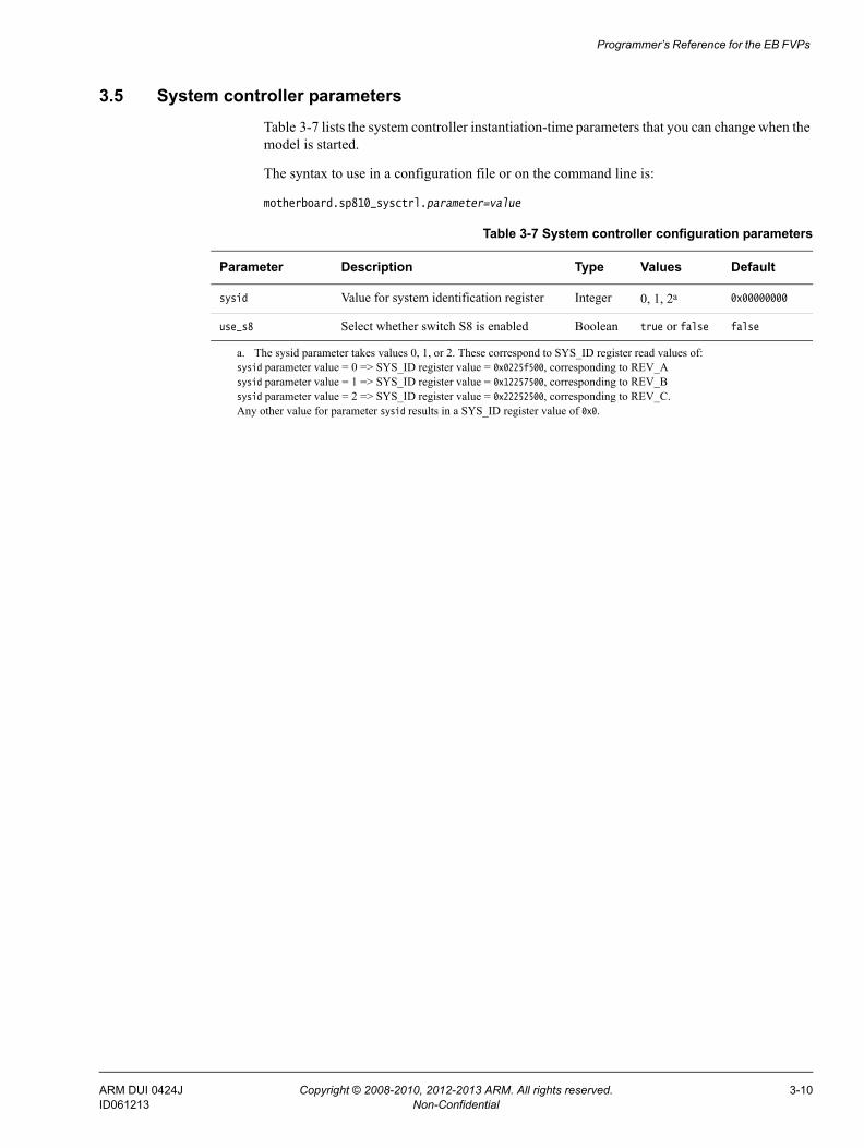
3.5 System controller parametersTable 3-7 lists the system controller instantiation-time parameters that you can change when the model is started.
The syntax to use in a configuration file or on the command line is:
motherboard.sp810_sysctrl.parameter=value
Table 3-7 System controller configuration parameters
Parameter Description Type Values Default
sysid Value for system identification register Integer 0, 1, 2a 0x00000000
use_s8 Select whether switch S8 is enabled Boolean true or false false
a. The sysid parameter takes values 0, 1, or 2. These correspond to SYS_ID register read values of:sysid parameter value = 0 => SYS_ID register value = 0x0225f500, corresponding to REV_Asysid parameter value = 1 => SYS_ID register value = 0x12257500, corresponding to REV_Bsysid parameter value = 2 => SYS_ID register value = 0x22252500, corresponding to REV_C.Any other value for parameter sysid results in a SYS_ID register value of 0x0.
ARM DUI 0424J Copyright © 2008-2010, 2012-2013 ARM. All rights reserved. 3-10ID061213 Non-Confidential
Programmer’s Reference for the EB FVPs
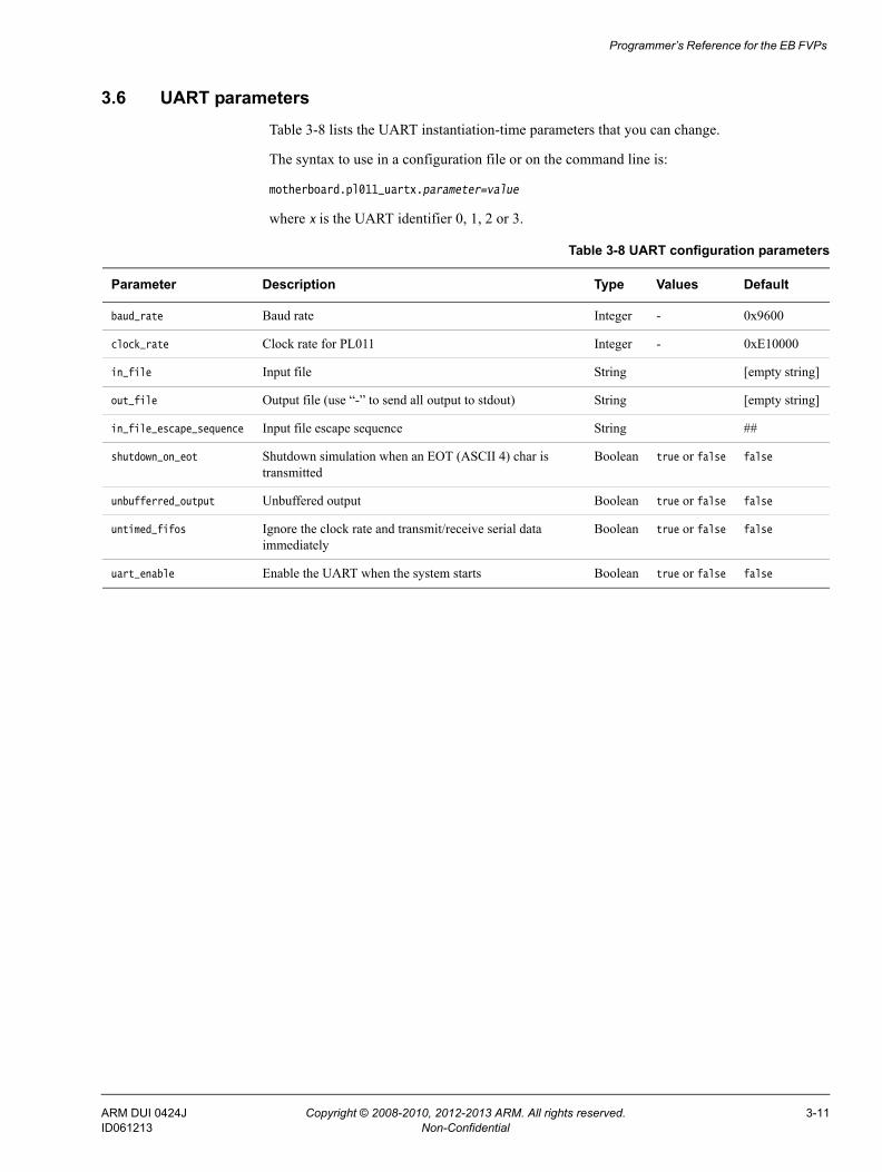
3.6 UART parametersTable 3-8 lists the UART instantiation-time parameters that you can change.
The syntax to use in a configuration file or on the command line is:
motherboard.pl011_uartx.parameter=value
where x is the UART identifier 0, 1, 2 or 3.
Table 3-8 UART configuration parameters
Parameter Description Type Values Default
baud_rate Baud rate Integer - 0x9600
clock_rate Clock rate for PL011 Integer - 0xE10000
in_file Input file String [empty string]
out_file Output file (use “-” to send all output to stdout) String [empty string]
in_file_escape_sequence Input file escape sequence String ##
shutdown_on_eot Shutdown simulation when an EOT (ASCII 4) char is transmitted
Boolean true or false false
unbufferred_output Unbuffered output Boolean true or false false
untimed_fifos Ignore the clock rate and transmit/receive serial data immediately
Boolean true or false false
uart_enable Enable the UART when the system starts Boolean true or false false
ARM DUI 0424J Copyright © 2008-2010, 2012-2013 ARM. All rights reserved. 3-11ID061213 Non-Confidential
Programmer’s Reference for the EB FVPs
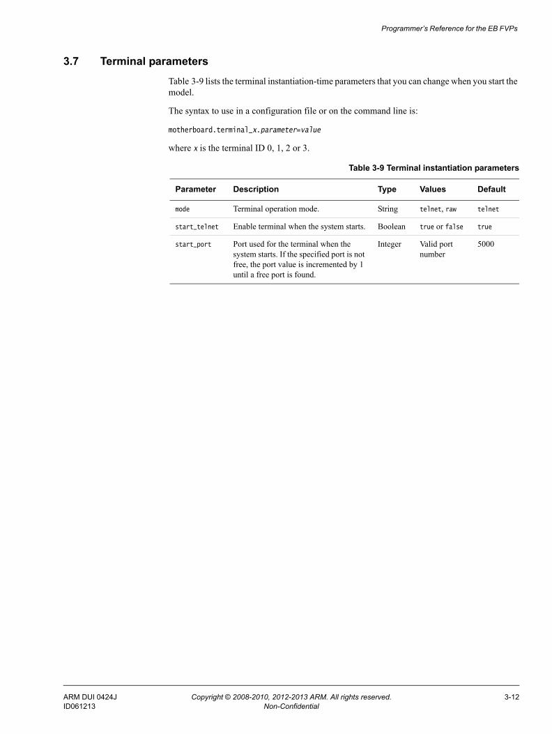
3.7 Terminal parametersTable 3-9 lists the terminal instantiation-time parameters that you can change when you start the model.
The syntax to use in a configuration file or on the command line is:
motherboard.terminal_x.parameter=value
where x is the terminal ID 0, 1, 2 or 3.
Table 3-9 Terminal instantiation parameters
Parameter Description Type Values Default
mode Terminal operation mode. String telnet, raw telnet
start_telnet Enable terminal when the system starts. Boolean true or false true
start_port Port used for the terminal when the system starts. If the specified port is not free, the port value is incremented by 1 until a free port is found.
Integer Valid port number
5000
ARM DUI 0424J Copyright © 2008-2010, 2012-2013 ARM. All rights reserved. 3-12ID061213 Non-Confidential
Programmer’s Reference for the EB FVPs
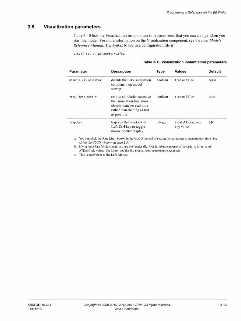
3.8 Visualization parametersTable 3-10 lists the Visualization instantiation-time parameters that you can change when you start the model. For more information on the Visualization component, see the Fast Models Reference Manual. The syntax to use in a configuration file is:
visualisation.parameter=value.
Table 3-10 Visualization instantiation parameters
Parameter Description Type Values Default
disable_visualisation disable the EBVisualisation component on model startup
boolean true or false false
rate_limit-enablea
a. You can click the Rate Limit button in the CLCD instead of setting the parameter at instantiation time. See Using the CLCD window on page 2-5.
restrict simulation speed so that simulation time more closely matches real time rather than running as fast as possible
boolean true or false true
trap_key trap key that works with Left Ctrl key to toggle mouse pointer display
integer valid ATKeyCode key valueb
b. If you have Fast Models installed, see the header file, %PVLIB_HOME%\components\KeyCode.h, for a list of ATKeyCode values. On Linux, see the file $PVLIB_HOME/components/KeyCode.h.
74c
c. This is equivalent to the Left Alt key.
ARM DUI 0424J Copyright © 2008-2010, 2012-2013 ARM. All rights reserved. 3-13ID061213 Non-Confidential
Programmer’s Reference for the EB FVPs
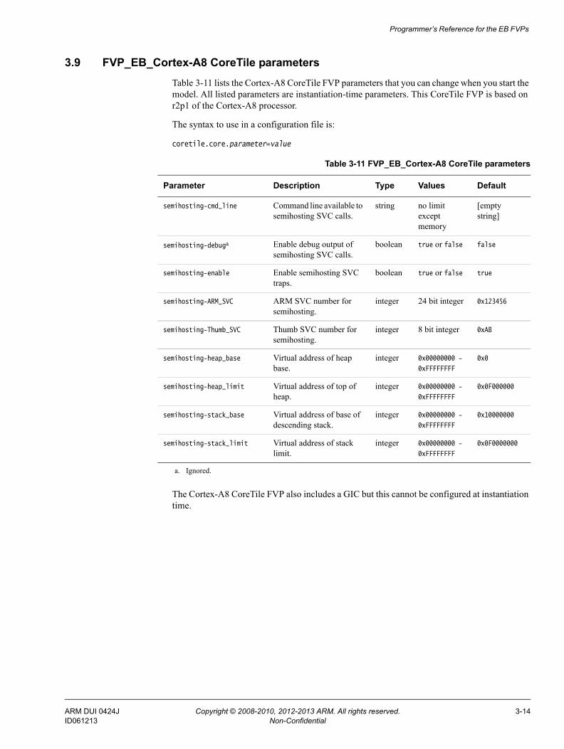
3.9 FVP_EB_Cortex-A8 CoreTile parametersTable 3-11 lists the Cortex-A8 CoreTile FVP parameters that you can change when you start the model. All listed parameters are instantiation-time parameters. This CoreTile FVP is based on r2p1 of the Cortex-A8 processor.
The syntax to use in a configuration file is:
coretile.core.parameter=value
The Cortex-A8 CoreTile FVP also includes a GIC but this cannot be configured at instantiation time.
Table 3-11 FVP_EB_Cortex-A8 CoreTile parameters
Parameter Description Type Values Default
semihosting-cmd_line Command line available to semihosting SVC calls.
string no limit except memory
[empty string]
semihosting-debuga
a. Ignored.
Enable debug output of semihosting SVC calls.
boolean true or false false
semihosting-enable Enable semihosting SVC traps.
boolean true or false true
semihosting-ARM_SVC ARM SVC number for semihosting.
integer 24 bit integer 0x123456
semihosting-Thumb_SVC Thumb SVC number for semihosting.
integer 8 bit integer 0xAB
semihosting-heap_base Virtual address of heap base.
integer 0x00000000 -
0xFFFFFFFF
0x0
semihosting-heap_limit Virtual address of top of heap.
integer 0x00000000 -
0xFFFFFFFF
0x0F000000
semihosting-stack_base Virtual address of base of descending stack.
integer 0x00000000 -
0xFFFFFFFF
0x10000000
semihosting-stack_limit Virtual address of stack limit.
integer 0x00000000 -
0xFFFFFFFF
0x0F0000000
ARM DUI 0424J Copyright © 2008-2010, 2012-2013 ARM. All rights reserved. 3-14ID061213 Non-Confidential
Programmer’s Reference for the EB FVPs
3.10 Differences between the EB and CoreTile hardware and the modelsThe following sections describe features of the Emulation Baseboard and CoreTile hardware that are not implemented in the models or have significant differences in implementation:• Features not present in the baseboard model• Restrictions on the processor models on page 3-16• Remapping and DRAM aliasing on page 3-17• Dynamic memory characteristics on page 3-17• Status and system control registers on page 3-17• Generic Interrupt Controller on page 3-18• GPIO2 on page 3-18• Timing considerations on page 3-18.
3.10.1 Features not present in the baseboard model
The following features present on the hardware version of the Emulation Baseboard are not implemented in the system models:• two wire serial bus interface• character LCD interface• smart card interface• PCI controller configuration registers• debug access port• disk on chip• configuration flash• USB• PISMO expansion memory• PCI interface bus windows• UART Modem handshake signals• VGA support.
Note For more information on memory-mapped peripherals, see EB model memory map on page 3-2.
The following features present on the hardware version of the Emulation Baseboard are only partially implemented in the Fixed Virtual Platforms:• Sound• Dynamic memory controller on page 3-16.
Partial implementation means that some of the components are present but the functionality has not been fully modeled. If you use these features, they might not work as you expect. See the model release notes for the latest information.
Sound
The EB FVPs implement the PL041 AACI PrimeCell and the audio codec as in the EB hardware, but with a limited number of sample rates.
ARM DUI 0424J Copyright © 2008-2010, 2012-2013 ARM. All rights reserved. 3-15ID061213 Non-Confidential
Programmer’s Reference for the EB FVPs
Dynamic memory controller
The dynamic memory controller, though modeled in the EB FVPs, does not provide direct memory access to all peripherals. Only the audio and synchronous serial port interface components can be accessed through the DMC.
3.10.2 Restrictions on the processor models
For detailed information concerning what features are not fully implemented in the processor models included with the EB FVPs, see the Fast Models Reference Manual. The following general restrictions apply to the Fixed Virtual Platform implementations of ARM processors:
• Fast Models does not model accurate instruction timing. A processor issues a set of instructions (a “quantum”) at a point in simulation time, and then waits before executing the next quantum. The processor averages one instruction per clock tick.Consequently:— The perceived performance of software running on the model differs from
real-world software. In particular, memory accesses and arithmetic operations all take the same amount of time.
— A program might be able to detect the quantized execution behavior of a processor, for example by polling a high-resolution timer.
— All instructions in a quantum are effectively atomic.
Note This might mask some race-condition bugs in software.
• Although cache control registers are included, in most cases they only enable you to check register access permissions. Cache flush operations are supported, but they have no effect. As a consequence, code that might fail on real hardware because of cache aliasing problems might run without problems on the EB FVP.
• VFP and NEON™ instruction set execution on the model is not high performance.
• Write buffers are not modeled.
• Most aspects of TLB behavior are implemented in the models. In Architecture v7 models, the TLB memory attribute settings are used when stateful cache is enabled.
• No MicroTLB is implemented.
• A single memory access port is implemented. The port combines accesses for instruction, data, DMA and peripherals. Configuration of the peripheral port memory map register is ignored.
• All memory accesses are atomic and are performed in programmer’s view order. All memory transactions are a maximum of 32 bits wide. Unaligned accesses are always performed as byte transfers.
• Interrupts are not taken at every instruction boundary.
• The semihosting-debug configuration parameter is ignored.
• Integration and test registers are not implemented.
• On some processor models, only one CP14 debug coprocessor register is included, CP14 DSCR. The register reads 0 and ignores writes. Access to other CP14 registers causes an undefined instruction exception. To debug an FVP you must use an external debugger.
ARM DUI 0424J Copyright © 2008-2010, 2012-2013 ARM. All rights reserved. 3-16ID061213 Non-Confidential
Programmer’s Reference for the EB FVPs
• Breakpoint types supported directly by the model are:— single address unconditional instruction breakpoints— single address unconditional data breakpoints— unconditional instruction address range breakpoints.
• Processor exception breakpoints are supported by pseudoregisters in the debugger. Setting an exception register to a nonzero value stops execution on entry to the associated exception vector.
• The Performance Management Unit (PMU) is not implemented except for the instruction counter.
FVP_EB_Cortex-A8 CoreTile
The following additional restrictions apply to the Fixed Virtual Platform implementation of the Cortex-A8 processor:
• Two 4GB address spaces are seen by the model core, one as seen from secure mode and one as seen from normal mode. The address spaces contain zero-wait state memory and peripherals, but a lot of the space is unmapped.
• The PLE model is purely register-based and has no implemented behavior.
• Unaligned accesses with the MMU disabled do not cause data aborts.
3.10.3 Remapping and DRAM aliasing
The EB hardware provides considerable memory remap functionality. During this boot remapping, the bottom 64MB of the physical address map can be:• NOR flash• Static expansion memory.
In addition to providing remap functionality, the hardware aliases all 256MB of system DRAM at 0x70000000.
Remapping does not typically apply to the system models. However, NOR flash is modeled and can be remapped. See Switch S8 on page 3-7.
In the memory map, memory regions that are not explicitly occupied by a peripheral or by memory are unmapped. This includes regions otherwise occupied by a peripheral that is not implemented, and those areas that are documented as reserved. Accessing these regions from the host processor results in the model presenting a warning.
3.10.4 Dynamic memory characteristics
The Emulation Baseboard hardware contains a PL340 DMC. This presents a configuration interface at address 0x10030000 in the memory map.
The system models configure a generic area of DRAM and do not model the PL340. This simplification helps speed the simulation.
3.10.5 Status and system control registers
For the hardware version of the Emulation Baseboard, the status and system control registers enable the processor to determine its environment and to control some on-board operations.
ARM DUI 0424J Copyright © 2008-2010, 2012-2013 ARM. All rights reserved. 3-17ID061213 Non-Confidential
Programmer’s Reference for the EB FVPs
Note Most of the EB FVP functionality is determined by its configuration on startup. See Configuring an FVP on page 2-3.
All EB system registers have been implemented in the system model, except for SYS_TEST_OSC[4:0], the oscillator test registers. Registers that are not implemented function as memory and the values written to them do not alter the behavior of the model.
3.10.6 Generic Interrupt Controller
The Generic Interrupt Controller (GIC) provided with the EB FVPs differs substantially from that in the Emulation Board firmware. The programmer’s model of the newer device is largely backwards compatible. The model GIC is an implementation of the PL390 PrimeCell, for which comprehensive documentation is provided elsewhere. See PrimeCell® Generic Interrupt Controller (PL390) Technical Reference Manual.
3.10.7 GPIO2
On the EB hardware, GPIO2 is dedicated to USB, a push button, and MCI status signals. USB and MCI are not implemented in the EB FVPs, and no push button is modeled. The GPIO is therefore provided as another generic IO device.
3.10.8 Timing considerations
The Fixed Virtual Platforms provide you with an environment that enables running software applications in a functionally-accurate simulation. However, because of the relative balance of fast simulation speed over timing accuracy, there are situations where the models might behave unexpectedly.
When your code interacts with real world devices like timers and keyboards, data arrives in the modeled device in real world (or wall clock) time, but simulation time can be running much faster than the wall clock. This means that a single keypress might be interpreted as several repeated key presses, or a single mouse click incorrectly becomes a double click.
The EB FVPs provide the Rate Limit feature to match simulation time to match wall-clock time. Enabling Rate Limit, either by using the Rate Limit button in the CLCD display, or the rate_limit-enable model instantiation parameter, forces the model to run at wall clock time. This avoids issues with two clocks running at significantly different rates. For interactive applications, ARM recommends enabling Rate Limit.
ARM DUI 0424J Copyright © 2008-2010, 2012-2013 ARM. All rights reserved. 3-18ID061213 Non-Confidential