Embed Size (px)
Citation preview
ARMv8 Instruction Set Overview
PRD03-GENC-010197 Copyright © 2009-2013 ARM Limited. All rights reserved. Page 1 of 115
ARMv8 Instruction Set Overview Architecture Group
Document number: PRD03-GENC-010197 30.0
Date of Issue: 3 June 2013
© Copyright ARM Limited 2009-2013. All rights reserved.
Abstract This document provides a high-level overview of the ARMv8 instructions sets, being mainly the new A64 instruction set used in AArch64 state but also those new instructions added to the A32 and T32 instruction sets since ARMv7-A for use in AArch32 state. For A64 this document specifies the preferred architectural assembly language notation to represent the new instruction set.
Keywords AArch64, A64, AArch32, A32, T32, ARMv8

ARMv8 Instruction Set Overview
PRD03-GENC-010197 Copyright © 2009-2013 ARM Limited. All rights reserved. Page 2 of 115
Proprietary Notice This specification is protected by copyright and the practice or implementation of the information herein may be protected by one or more patents or pending applications. No part of this specification may be reproduced in any form by any means without the express prior written permission of ARM. No license, express or implied, by estoppel or otherwise to any intellectual property rights is granted by this specification. Your access to the information in this specification is conditional upon your acceptance that you will not use or permit others to use the information for the purposes of determining whether implementations of the ARM architecture infringe any third party patents. This specification is provided “as is”. ARM makes no representations or warranties, either express or implied, included but not limited to, warranties of merchantability, fitness for a particular purpose, or non-infringement, that the content of this specification is suitable for any particular purpose or that any practice or implementation of the contents of the specification will not infringe any third party patents, copyrights, trade secrets, or other rights. This specification may include technical inaccuracies or typographical errors. To the extent not prohibited by law, in no event will ARM be liable for any damages, including without limitation any direct loss, lost revenue, lost profits or data, special, indirect, consequential, incidental or punitive damages, however caused and regardless of the theory of liability, arising out of or related to any furnishing, practicing, modifying or any use of this specification, even if ARM has been advised of the possibility of such damages. Words and logos marked with ® or TM are registered trademarks or trademarks of ARM Limited, except as otherwise stated below in this proprietary notice. Other brands and names mentioned herein may be the trademarks of their respective owners. Copyright © 2009-2013 ARM Limited 110 Fulbourn Road, Cambridge, England CB1 9NJ Restricted Rights Legend: Use, duplication or disclosure by the United States Government is subject to the restrictions set forth in DFARS 252.227-7013 (c)(1)(ii) and FAR 52.227-19. This document is Non-Confidential but any disclosure by you is subject to you providing notice to and the acceptance by the recipient of, the conditions set out above. In this document, where the term ARM is used to refer to the company it means “ARM or any of its subsidiaries as appropriate”.
ARMv8 Instruction Set Overview
PRD03-GENC-010197 Copyright © 2009-2013 ARM Limited. All rights reserved. Page 3 of 115
Contents
ABSTRACT 1
KEYWORDS 1
PROPRIETARY NOTICE 2
CONTENTS 3
1 ABOUT THIS DOCUMENT 7
1.1 Change control 7 1.1.1 Current status and anticipated changes 7 1.1.2 Change history 7
1.2 References 9
1.3 Terms and abbreviations 9
2 INTRODUCTION 10
3 A64 OVERVIEW 10
3.1 Distinguishing 32-bit and 64-bit Instructions 12
3.2 Conditional Instructions 12
3.3 Addressing Features 13 3.3.1 Register Indexed Addressing 13 3.3.2 PC-relative Addressing 13
3.4 The Program Counter (PC) 13
3.5 Memory Load-Store 13 3.5.1 Bulk Transfers 13 3.5.2 Exclusive Accesses 14 3.5.3 Load-Acquire, Store-Release 14
3.6 Integer Multiply/Divide 14
3.7 Scalar Floating Point 14
3.8 Advanced SIMD 15
4 A64 ASSEMBLY LANGUAGE 16
4.1 Basic Structure 16
4.2 Instruction Mnemonics 16
ARMv8 Instruction Set Overview
PRD03-GENC-010197 Copyright © 2009-2013 ARM Limited. All rights reserved. Page 4 of 115
4.3 Condition Codes 17
4.4 Register Names 19 4.4.1 General purpose (integer) registers 19 4.4.2 FP/SIMD registers 20
4.5 Load/Store Addressing Modes 22 4.5.1 Address Computation 23
5 A64 INSTRUCTION SET 24
5.1 Common Terms 24
5.2 Control Flow 25 5.2.1 Conditional Branch 25 5.2.2 Unconditional Branch (immediate) 25 5.2.3 Unconditional Branch (register) 25
5.3 Memory Access 26 5.3.1 Load-Store Single Register 26 5.3.2 Load-Store Single Register (unscaled offset) 27 5.3.3 Load-Store Pair 28 5.3.4 Load-Store Non-temporal Pair 29 5.3.5 Load-Store Unprivileged 30 5.3.6 Load-Store Exclusive 31 5.3.7 Load-Acquire / Store-Release 32 5.3.8 Prefetch Memory 34
5.4 Data Processing (immediate) 34 5.4.1 Arithmetic (immediate) 35 5.4.2 Logical (immediate) 36 5.4.3 Move (wide immediate) 37 5.4.4 PC-relative Address Calculation 38 5.4.5 Bitfield Operations 38 5.4.6 Extract (immediate) 40 5.4.7 Shift (immediate) 40 5.4.8 Sign/Zero Extend 40
5.5 Data Processing (register) 40 5.5.1 Arithmetic (shifted register) 41 5.5.2 Arithmetic (extended register) 42 5.5.3 Logical (shifted register) 43 5.5.4 Variable Shift 45 5.5.5 Bit Operations 46 5.5.6 Conditional Data Processing 46 5.5.7 Conditional Comparison 48
5.6 Integer Multiply / Divide 49 5.6.1 Multiply 49 5.6.2 Divide 50 5.6.3 CRC 51
5.7 Scalar Floating-point 52 5.7.1 Floating-point/SIMD Scalar Memory Access 52 5.7.2 Floating-point Move (register) 55
ARMv8 Instruction Set Overview
PRD03-GENC-010197 Copyright © 2009-2013 ARM Limited. All rights reserved. Page 5 of 115
5.7.3 Floating-point Move (immediate) 55 5.7.4 Floating-point Convert 56 5.7.5 Floating-point Round to Integral 58 5.7.6 Floating-point Arithmetic (1 source) 59 5.7.7 Floating-point Arithmetic (2 source) 59 5.7.8 Floating-point Min/Max 59 5.7.9 Floating-point Multiply-Add 60 5.7.10 Floating-point Comparison 60 5.7.11 Floating-point Conditional Select 61
5.8 Advanced SIMD 62 5.8.1 Overview 62 5.8.2 Advanced SIMD Mnemonics 63 5.8.3 Data Movement 63 5.8.4 Vector Arithmetic 65 5.8.5 Vector Compare 68 5.8.6 Scalar Arithmetic 69 5.8.7 Scalar Compare 70 5.8.8 Vector Widening/Narrowing Arithmetic 71 5.8.9 Scalar Widening/Narrowing Arithmetic 74 5.8.10 Vector Unary Arithmetic 74 5.8.11 Scalar Unary Arithmetic 76 5.8.12 Vector-by-element Arithmetic 77 5.8.13 Scalar-by-element Arithmetic 79 5.8.14 Vector Permute 79 5.8.15 Vector Immediate 80 5.8.16 Vector Shift (immediate) 81 5.8.17 Scalar Shift (immediate) 84 5.8.18 Vector Floating Point / Integer Convert 85 5.8.19 Scalar Floating Point / Integer Convert 86 5.8.20 Vector Reduce (across vector lanes) 86 5.8.21 Vector Pairwise Arithmetic 87 5.8.22 Scalar Pairwise Reduce 88 5.8.23 Vector Table Lookup 88 5.8.24 Vector Load-Store Structure 89 5.8.25 AArch32 Equivalent Advanced SIMD Mnemonics 91 5.8.26 Crypto Extension 98
5.9 System Instructions 99 5.9.1 Exception Generation and Return 99 5.9.2 System Register Access 100 5.9.3 System Management 100 5.9.4 Architectural Hints 104 5.9.5 Barriers and CLREX 104
6 A32 & T32 INSTRUCTION SETS 106
6.1 Partial Deprecation of IT 107
6.2 Load-Acquire / Store-Release 107 6.2.1 Non-Exclusive 107 6.2.2 Exclusive 108
6.3 CRC 109
ARMv8 Instruction Set Overview
PRD03-GENC-010197 Copyright © 2009-2013 ARM Limited. All rights reserved. Page 6 of 115
6.4 VFP Scalar Floating-point 110 6.4.1 Floating-point Conditional Select 110 6.4.2 Floating-point minNum/maxNum 110 6.4.3 Floating-point Convert (floating-point to integer) 110 6.4.4 Floating-point Convert (half-precision to/from double-precision) 111 6.4.5 Floating-point Round to Integral 111
6.5 Advanced SIMD Floating-Point 112 6.5.1 Floating-point minNum/maxNum 112 6.5.2 Floating-point Convert 112 6.5.3 Floating-point Round to Integral 112
6.6 Crypto Extension 113
6.7 System Instructions 114 6.7.1 Halting Debug 114 6.7.2 Barriers and Hints 114 6.7.3 TLB Maintenance 114
ARMv8 Instruction Set Overview
PRD03-GENC-010197 Copyright © 2009-2013 ARM Limited. All rights reserved. Page 7 of 115
1 ABOUT THIS DOCUMENT
1.1 Change control
1.1.1 Current status and anticipated changes This document is a released specification although further changes to correct defects and improve clarity should be expected.
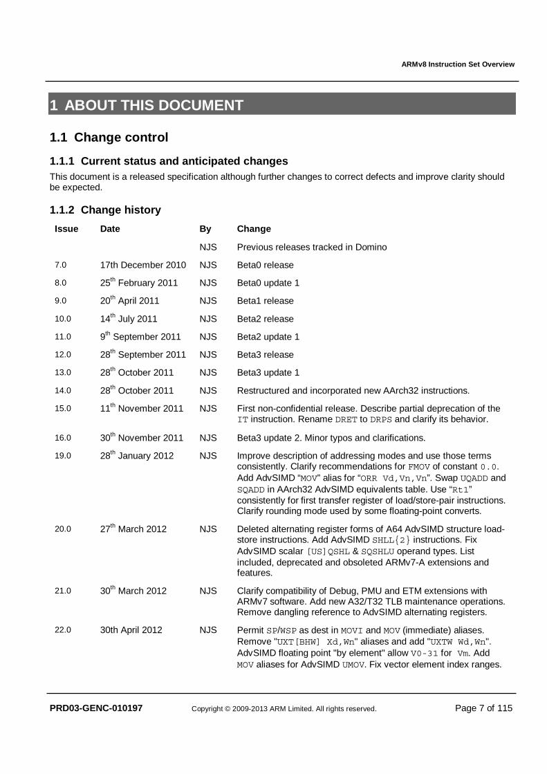
1.1.2 Change history
Issue Date By Change
NJS Previous releases tracked in Domino
7.0 17th December 2010 NJS Beta0 release
8.0 25th February 2011 NJS Beta0 update 1
9.0 20th April 2011 NJS Beta1 release
10.0 14th July 2011 NJS Beta2 release
11.0 9th September 2011 NJS Beta2 update 1
12.0 28th September 2011 NJS Beta3 release
13.0 28th October 2011 NJS Beta3 update 1
14.0 28th October 2011 NJS Restructured and incorporated new AArch32 instructions.
15.0 11th November 2011 NJS First non-confidential release. Describe partial deprecation of the IT instruction. Rename DRET to DRPS and clarify its behavior.
16.0 30th November 2011 NJS Beta3 update 2. Minor typos and clarifications.
19.0 28th January 2012 NJS Improve description of addressing modes and use those terms consistently. Clarify recommendations for FMOV of constant 0.0. Add AdvSIMD “MOV” alias for “ORR Vd,Vn,Vn”. Swap UQADD and SQADD in AArch32 AdvSIMD equivalents table. Use “Rt1” consistently for first transfer register of load/store-pair instructions. Clarify rounding mode used by some floating-point converts.
20.0 27th March 2012 NJS Deleted alternating register forms of A64 AdvSIMD structure load-store instructions. Add AdvSIMD SHLL{2} instructions. Fix AdvSIMD scalar [US]QSHL & SQSHLU operand types. List included, deprecated and obsoleted ARMv7-A extensions and features.
21.0 30th March 2012 NJS Clarify compatibility of Debug, PMU and ETM extensions with ARMv7 software. Add new A32/T32 TLB maintenance operations. Remove dangling reference to AdvSIMD alternating registers.
22.0 30th April 2012 NJS Permit SP/WSP as dest in MOVI and MOV (immediate) aliases. Remove "UXT[BHW] Xd,Wn" aliases and add "UXTW Wd,Wn". AdvSIMD floating point "by element" allow V0-31 for Vm. Add MOV aliases for AdvSIMD UMOV. Fix vector element index ranges.
ARMv8 Instruction Set Overview
PRD03-GENC-010197 Copyright © 2009-2013 ARM Limited. All rights reserved. Page 8 of 115
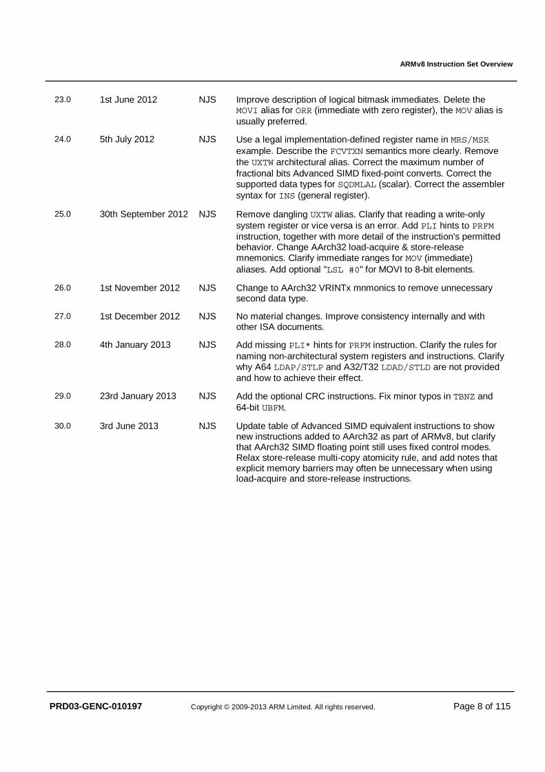
23.0 1st June 2012 NJS Improve description of logical bitmask immediates. Delete the MOVI alias for ORR (immediate with zero register), the MOV alias is usually preferred.
24.0 5th July 2012 NJS Use a legal implementation-defined register name in MRS/MSR example. Describe the FCVTXN semantics more clearly. Remove the UXTW architectural alias. Correct the maximum number of fractional bits Advanced SIMD fixed-point converts. Correct the supported data types for SQDMLAL (scalar). Correct the assembler syntax for INS (general register).
25.0 30th September 2012 NJS Remove dangling UXTW alias. Clarify that reading a write-only system register or vice versa is an error. Add PLI hints to PRFM instruction, together with more detail of the instruction's permitted behavior. Change AArch32 load-acquire & store-release mnemonics. Clarify immediate ranges for MOV (immediate) aliases. Add optional "LSL #0" for MOVI to 8-bit elements.
26.0 1st November 2012 NJS Change to AArch32 VRINTx mnmonics to remove unnecessary second data type.
27.0 1st December 2012 NJS No material changes. Improve consistency internally and with other ISA documents.
28.0 4th January 2013 NJS Add missing PLI* hints for PRFM instruction. Clarify the rules for naming non-architectural system registers and instructions. Clarify why A64 LDAP/STLP and A32/T32 LDAD/STLD are not provided and how to achieve their effect.
29.0 23rd January 2013 NJS Add the optional CRC instructions. Fix minor typos in TBNZ and 64-bit UBFM.
30.0 3rd June 2013 NJS Update table of Advanced SIMD equivalent instructions to show new instructions added to AArch32 as part of ARMv8, but clarify that AArch32 SIMD floating point still uses fixed control modes. Relax store-release multi-copy atomicity rule, and add notes that explicit memory barriers may often be unnecessary when using load-acquire and store-release instructions.
ARMv8 Instruction Set Overview
PRD03-GENC-010197 Copyright © 2009-2013 ARM Limited. All rights reserved. Page 9 of 115
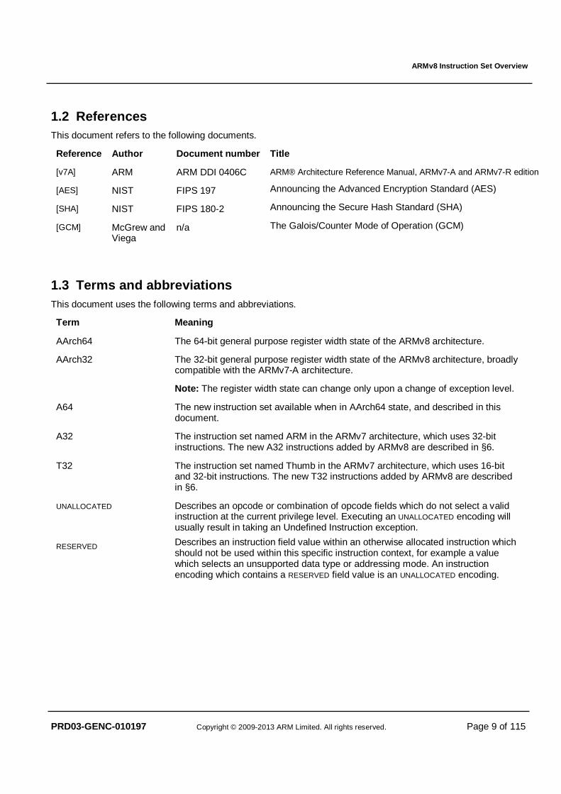
1.2 References This document refers to the following documents.
Reference Author Document number Title
[v7A] ARM ARM DDI 0406C ARM® Architecture Reference Manual, ARMv7-A and ARMv7-R edition
[AES] NIST FIPS 197 Announcing the Advanced Encryption Standard (AES)
[SHA] NIST FIPS 180-2 Announcing the Secure Hash Standard (SHA)
[GCM] McGrew and Viega
n/a The Galois/Counter Mode of Operation (GCM)
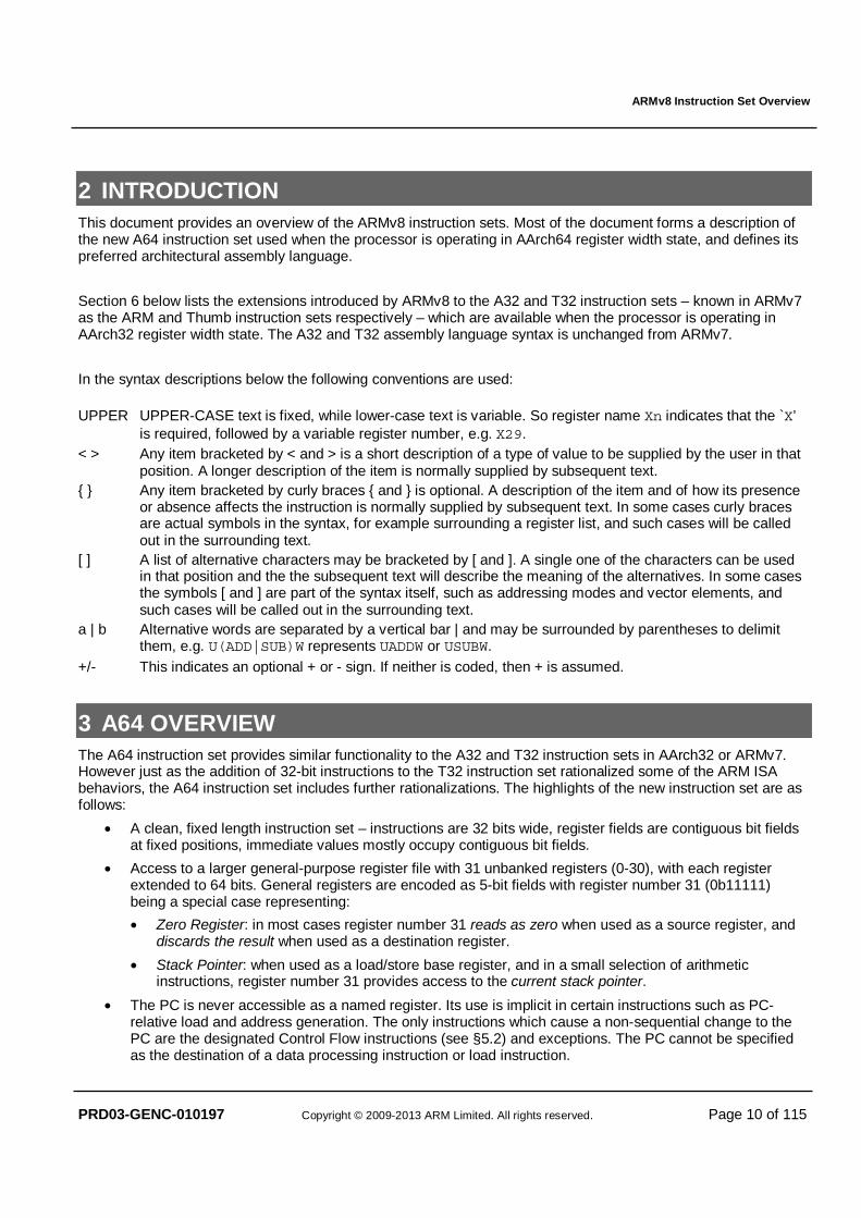
1.3 Terms and abbreviations This document uses the following terms and abbreviations.
Term Meaning
AArch64 The 64-bit general purpose register width state of the ARMv8 architecture.
AArch32 The 32-bit general purpose register width state of the ARMv8 architecture, broadly compatible with the ARMv7-A architecture.
Note: The register width state can change only upon a change of exception level.
A64 The new instruction set available when in AArch64 state, and described in this document.
A32 The instruction set named ARM in the ARMv7 architecture, which uses 32-bit instructions. The new A32 instructions added by ARMv8 are described in §6.
T32 The instruction set named Thumb in the ARMv7 architecture, which uses 16-bit and 32-bit instructions. The new T32 instructions added by ARMv8 are described in §6.
UNALLOCATED Describes an opcode or combination of opcode fields which do not select a valid instruction at the current privilege level. Executing an UNALLOCATED encoding will usually result in taking an Undefined Instruction exception.
RESERVED Describes an instruction field value within an otherwise allocated instruction which should not be used within this specific instruction context, for example a value which selects an unsupported data type or addressing mode. An instruction encoding which contains a RESERVED field value is an UNALLOCATED encoding.
ARMv8 Instruction Set Overview
PRD03-GENC-010197 Copyright © 2009-2013 ARM Limited. All rights reserved. Page 10 of 115
2 INTRODUCTION This document provides an overview of the ARMv8 instruction sets. Most of the document forms a description of the new A64 instruction set used when the processor is operating in AArch64 register width state, and defines its preferred architectural assembly language.
Section 6 below lists the extensions introduced by ARMv8 to the A32 and T32 instruction sets – known in ARMv7 as the ARM and Thumb instruction sets respectively – which are available when the processor is operating in AArch32 register width state. The A32 and T32 assembly language syntax is unchanged from ARMv7.
In the syntax descriptions below the following conventions are used: UPPER UPPER-CASE text is fixed, while lower-case text is variable. So register name Xn indicates that the `X’
is required, followed by a variable register number, e.g. X29. < > Any item bracketed by < and > is a short description of a type of value to be supplied by the user in that
position. A longer description of the item is normally supplied by subsequent text. { } Any item bracketed by curly braces { and } is optional. A description of the item and of how its presence
or absence affects the instruction is normally supplied by subsequent text. In some cases curly braces are actual symbols in the syntax, for example surrounding a register list, and such cases will be called out in the surrounding text.
[ ] A list of alternative characters may be bracketed by [ and ]. A single one of the characters can be used in that position and the the subsequent text will describe the meaning of the alternatives. In some cases the symbols [ and ] are part of the syntax itself, such as addressing modes and vector elements, and such cases will be called out in the surrounding text.
a | b Alternative words are separated by a vertical bar | and may be surrounded by parentheses to delimit them, e.g. U(ADD|SUB)W represents UADDW or USUBW.
+/- This indicates an optional + or - sign. If neither is coded, then + is assumed.
3 A64 OVERVIEW The A64 instruction set provides similar functionality to the A32 and T32 instruction sets in AArch32 or ARMv7. However just as the addition of 32-bit instructions to the T32 instruction set rationalized some of the ARM ISA behaviors, the A64 instruction set includes further rationalizations. The highlights of the new instruction set are as follows:
• A clean, fixed length instruction set – instructions are 32 bits wide, register fields are contiguous bit fields at fixed positions, immediate values mostly occupy contiguous bit fields.
• Access to a larger general-purpose register file with 31 unbanked registers (0-30), with each register extended to 64 bits. General registers are encoded as 5-bit fields with register number 31 (0b11111) being a special case representing:
• Zero Register: in most cases register number 31 reads as zero when used as a source register, and discards the result when used as a destination register.
• Stack Pointer: when used as a load/store base register, and in a small selection of arithmetic instructions, register number 31 provides access to the current stack pointer.
• The PC is never accessible as a named register. Its use is implicit in certain instructions such as PC-relative load and address generation. The only instructions which cause a non-sequential change to the PC are the designated Control Flow instructions (see §5.2) and exceptions. The PC cannot be specified as the destination of a data processing instruction or load instruction.
ARMv8 Instruction Set Overview
PRD03-GENC-010197 Copyright © 2009-2013 ARM Limited. All rights reserved. Page 11 of 115
• The procedure call link register (LR) is unbanked, general-purpose register 30; exceptions save the restart PC to the target exception level’s ELR system register.
• Scalar load/store addressing modes are uniform across all sizes and signedness of scalar integer, floating point and vector registers.
• A load/store immediate offset may be scaled by the access size, increasing its effective offset range.
• A load/store index register may contain a 64-bit or 32-bit signed/unsigned value, optionally scaled by the access size.
• Arithmetic instructions for address generation which mirror the load/store addressing modes, see §3.3.
• PC-relative load/store and address generation with a range of ±4GiB is possible using just two instructions without the need to load an offset from a literal pool.
• PC-relative offsets for literal pool access and most conditional branches are extended to ±1MiB, and for unconditional branches and calls to ±128MiB.
• There are no multiple register LDM, STM, PUSH and POP instructions, but load-store of a non-contiguous pair of registers is available.
• Unaligned addresses are permitted for most loads and stores, including paired register accesses, floating point and SIMD registers, with the exception of exclusive and ordered accesses (see §3.5.2).
• Reduced conditionality. Fewer instructions can set the condition flags. Only conditional branches, and a handful of data processing instructions read the condition flags. Conditional or predicated execution is not provided, and there is no equivalent of T32’s IT instruction (see §3.2).
• A shift option for the final register operand of data processing instructions is available:
o Immediate shifts only (as in T32).
o No RRX shift, and no ROR shift for ADD/SUB.
o The ADD/SUB/CMP instructions can first sign or zero-extend a byte, halfword or word in the final register operand, followed by an optional left shift of 1 to 4 bits.
• Immediate generation replaces A32’s rotated 8-bit immediate with operation-specific encodings:
o Arithmetic instructions have a simple 12-bit immediate, with an optional left shift by 12.
o Logical instructions provide sophisticated replicating bit mask generation.
o Other immediates may be constructed inline in 16-bit “chunks”, extending upon the MOVW and MOVT instructions of AArch32.
• Floating point support is similar to AArch32 VFP but with some extensions, as described in §3.6.
• Floating point and Advanced SIMD processing share a register file, in a similar manner to AArch32, but extended to thirty-two 128-bit registers. Smaller registers are no longer packed into larger registers, but are mapped one-to-one to the low-order bits of the 128-bit register, as described in §4.4.2.
• There are no SIMD or saturating arithmetic instructions which operate on the general purpose registers, such operations being available only as part of the Advanced SIMD processing, described in §5.8.
• There is no access to CPSR as a single register, but new system instructions provide the ability to atomically modify individual processor state fields, see §5.9.2.
• The concept of a “coprocessor” is removed from the architecture. A set of system instructions described in §5.9 provides:
o System register access
o Cache/TLB management
o VA�PA translation
o Barriers and CLREX
o Architectural hints (WFI, etc)
o Debug
ARMv8 Instruction Set Overview
PRD03-GENC-010197 Copyright © 2009-2013 ARM Limited. All rights reserved. Page 12 of 115
3.1 Distinguishing 32-bit and 64-bit Instructions Most integer instructions in the A64 instruction set have two forms, which operate on either 32-bit or 64-bit values within the 64-bit general-purpose register file. Where a 32-bit instruction form is selected, the following holds true:
• The upper 32 bits of the source registers are ignored;
• The upper 32 bits of the destination register are set to ZERO;
• Right shifts/rotates inject at bit 31, instead of bit 63;
• The condition flags, where set by the instruction, are computed from the lower 32 bits.
This distinction applies even when the result(s) of a 32-bit instruction form would be indistinguishable from the lower 32 bits computed by the equivalent 64-bit instruction form. For example a 32-bit bitwise ORR could be performed using a 64-bit ORR, and simply ignoring the top 32 bits of the result. But the A64 instruction set includes separate 32 and 64-bit forms of the ORR instruction.
Rationale: The C/C++ LP64 and LLP64 data models – expected to be the most commonly used on AArch64 – both define the frequently used int, short and char types to be 32 bits or less. By maintaining this semantic information in the instruction set, implementations can exploit this information to avoid expending energy or cycles to compute, forward and store the unused upper 32 bits of such data types. Implementations are free to exploit this freedom in whatever way they choose to save energy.
As well as distinct sign/zero-extend instructions, the A64 instruction set also provides the ability to extend and shift the final source register of an ADD, SUB or CMP instruction and the index register of a load/store instruction. This allows for an efficient implementation of array index calculations involving a 64-bit array pointer and 32-bit array index.
The assembly language notation is designed to allow the identification of registers holding 32-bit values as distinct from those holding 64-bit values. As well as aiding readability, tools may be able to use this to perform limited type checking, to identify programming errors resulting from the change in register size.
3.2 Conditional Instructions The A64 instruction set does not include the concept of predicated or conditional execution. Benchmarking shows that modern branch predictors work well enough that predicated execution of instructions does not offer sufficient benefit to justify its significant use of opcode space, and its implementation cost in advanced implementations.
A very small set of “conditional data processing” instructions are provided. These instructions are unconditionally executed but use the condition flags as an extra input to the instruction. This set has been shown to be beneficial in situations where conditional branches predict poorly, or are otherwise inefficient.
The conditional instruction types are:
• Conditional branch: the traditional ARM conditional branch, together with compare and branch if register zero/non-zero, and test single bit in register and branch if zero/non-zero – all with increased displacement.
• Add/subtract with carry: the traditional ARM instructions, for multi-precision arithmetic, checksums, etc.
• Conditional select with increment, negate or invert: conditionally select between one source register and a second incremented/negated/inverted/unmodified source register. Benchmarking reveals these to be the highest frequency uses of single conditional instructions, e.g. for counting, absolute value, etc. These instructions also implement:
o Conditional select (move): sets the destination to one of two source registers, selected by the condition flags. Short conditional sequences can be replaced by unconditional instructions followed by a conditional select.
o Conditional set: conditionally select between 0 and 1 or -1, for example to materialize the condition flags as a Boolean value or mask in a general register.
• Conditional compare: sets the condition flags to the result of a comparison if the original condition was true, else to an immediate value. Permits the flattening of nested conditional expressions without using conditional branches or performing Boolean arithmetic within general registers.
ARMv8 Instruction Set Overview
PRD03-GENC-010197 Copyright © 2009-2013 ARM Limited. All rights reserved. Page 13 of 115
3.3 Addressing Features The prime motivation for a 64-bit architecture is access to a larger virtual address space. The AArch64 memory translation system supports a 49-bit virtual address (48 bits per translation table). Virtual addresses are sign-extended from 49 bits, and stored within a 64-bit pointer. Optionally, under control of a system register, the most significant 8 bits of a 64-bit pointer may hold a “tag” which will be ignored when used as a load/store address or the target of an indirect branch.
3.3.1 Register Indexed Addressing The A64 instruction set extends on 32-bit T32 addressing modes, allowing a 64-bit index register to be added to the 64-bit base register, with optional scaling of the index by the access size. Additionally it provides for sign or zero-extension of a 32-bit value within an index register, again with optional scaling.
These register index addressing modes provide a useful performance gain if they can be performed within a single cycle, and it is believed that at least some implementations will be able to do this. However, based on implementation experience with AArch32, it is expected that other implementations will need an additional cycle to execute such addressing modes.
Rationale: The architects intend that implementations should be free to fine-tune the performance trade-offs within each implementation, and note that providing an instruction which in some implementations takes two cycles, is preferable to requiring the dynamic grouping of two independent instructions in an implementation that can perform this address arithmetic in a single cycle.
3.3.2 PC-relative Addressing There is improved support for position-independent code and data addressing:
• PC-relative literal loads have an offset range of ±1MiB. This permits fewer literal pools, and more sharing of literal data between functions – reducing I-cache and TLB pollution.
• Most conditional branches have a range of ±1MiB, expected to be sufficient for the majority of conditional branches which take place within a single function.
• Unconditional branches, including branch and link, have a range of ±128MiB. Expected to be sufficient to span the static code segment of most executable load modules and shared objects, without needing linker-inserted trampolines or “veneers”.
• PC-relative load/store and address generation with a range of ±4GiB may be performed inline using only two instructions, i.e. without the need to load an offset from a literal pool.
3.4 The Program Counter (PC) The current Program Counter (PC) cannot be referred to by number as if part of the general register file and therefore cannot be used as the source or destination of arithmetic instructions, or as the base, index or transfer register of load/store instructions. The only instructions which read the PC are those whose function is to compute a PC-relative address (ADR, ADRP, literal load, and direct branches), and the branch-and-link instructions which store it in the link register (BL and BLR). The only way to modify the Program Counter is using explicit control flow instructions: conditional branch, unconditional branch, exception generation and exception return instructions.
Where the PC is read by an instruction to compute a PC-relative address, then its value is the address of the instruction, i.e. unlike A32 and T32 there is no implied offset of 4 or 8 bytes.
3.5 Memory Load-Store
3.5.1 Bulk Transfers The LDM, STM, PUSH and POP instructions do not exist in A64, however bulk transfers can be constructed using the LDP and STP instructions which load and store a pair of independent registers from consecutive memory locations, and which support unaligned addresses when accessing normal memory. The LDNP and
ARMv8 Instruction Set Overview
PRD03-GENC-010197 Copyright © 2009-2013 ARM Limited. All rights reserved. Page 14 of 115
STNP instructions additionally provide a “streaming” or ”non-temporal” hint that the data does not need to be retained in caches. The PRFM (prefetch memory) instructions also include hints for “streaming” or “non-temporal” accesses, and allow targeting of a prefetch to a specific cache level.
3.5.2 Exclusive Accesses Exclusive load-store of a byte, halfword, word and doubleword. Exclusive access to a pair of doublewords permit atomic updates of a pair of pointers, for example circular list inserts. All exclusive accesses must be naturally aligned, and exclusive pair access must be aligned to twice the data size (i.e. 16 bytes for a 64-bit pair).
3.5.3 Load-Acquire, Store-Release Explicitly synchronising load and store instructions implement the release-consistency (RCsc) memory model, reducing the need for explicit memory barriers, and providing a good match to emerging language standards for shared memory. The instructions exist in both exclusive and non-exclusive forms, and require natural address alignment. See §5.3.7 for more details.
3.6 Integer Multiply/Divide Including 32 and 64-bit multiply, with accumulation:
� 32 ± (32 � 32) → 32
� 64 ± (64 � 64) → 64
� ± (32 � 32) → 32
� ± (64 � 64) → 64
Widening multiply (signed and unsigned), with accumulation:
� 64 ± (32 � 32) → 64
� ± (32 � 32) → 64
� (64 � 64) → hi64 <127:64>
Multiply instructions write a single register. A 64 � 64 to 128-bit multiply requires a sequence of two instructions to generate a pair of 64-bit result registers:
� + (64 � 64) → <63:0>
� (64 � 64) → <127:64>
Signed and unsigned 32- and 64-bit divide are also provided. A remainder instruction is not provided, but a remainder may be computed easily from the dividend, divisor and quotient using an MSUB instruction. There is no hardware check for “divide by zero”, but this check can be performed in the shadow of a long latency division. A divide by zero writes zero to the destination register.
3.7 Scalar Floating Point AArch64 mandates hardware floating point wherever floating point arithmetic is required – there is no “soft-float” variant of the AArch64 Procedure Calling Standard (PCS).
Scalar floating point functionality is similar to AArch32 VFP, with the following changes:
• The deprecated “small vector” feature of VFP is removed.
• There are 32 S registers and 32 D registers. The S registers are not packed into D registers, but occupy the low 32 bits of the corresponding D register. For example S31=D31<31:0>, not D15<63:32>.
• Load/store addressing modes identical to integer load/stores.
• Load/store of a pair of floating point registers.
• Floating point FCSEL and FCCMP equivalent to the integer CSEL and CCMP.
ARMv8 Instruction Set Overview
PRD03-GENC-010197 Copyright © 2009-2013 ARM Limited. All rights reserved. Page 15 of 115
• Floating point FCMP and FCCMP instructions set the integer condition flags directly, and do not modify the condition flags in the FPSR.
• All floating-point multiply-add and multiply-subtract instructions are “fused”.
• Convert between 64-bit integer and floating point.
• Convert FP to integer with explicit rounding direction: towards zero, towards +Inf, towards -Inf, nearest with ties to even, and nearest with ties to away.
• Round FP to nearest integral FP with explicit rounding direction (as above).
• Direct conversion between half-precision and double-precision.
• FMINNM & FMAXNM implementing the IEEE754-2008 minNum() and maxNum() operations, returning the numerical value if one of the operands is a quiet NaN.
3.8 Advanced SIMD See §5.8 below for a detailed description.
ARMv8 Instruction Set Overview
PRD03-GENC-010197 Copyright © 2009-2013 ARM Limited. All rights reserved. Page 16 of 115
4 A64 ASSEMBLY LANGUAGE
4.1 Basic Structure The letter W is shorthand for a 32-bit word, and X for a 64-bit extended word. The letter X (extended) is used rather than D (double), since D conflicts with its use for floating point and SIMD “double-precision” registers and the T32 load/store “double-register” instructions (e.g. LDRD).
An A64 assembler will recognise both upper and lower-case variants of instruction mnemonics and register names, but not mixed case. An A64 disassembler may output either upper or lower-case mnemonics and register names. The case of program and data labels is significant.
The fundamental statement format and operand order follows that used by AArch32 UAL assemblers and disassemblers, i.e. a single statement per source line, consisting of one or more optional program labels, followed by an instruction mnemonic, then a destination register and one or more source operands separated by commas.
{label:*} {opcode {dest{, source1{, source2{, source3}}}}}
This dest/source ordering is reversed for store instructions, in common with AArch32 UAL.
The A64 assembly language does not require the ‘#’ symbol to introduce immediate values, though an assembler must allow it. An A64 disassembler shall always output a ‘#’ before an immediate value for readability.
Where a user-defined symbol or label is identical to a pre-defined register name (e.g. “X0”) then if it is used in a context where its interpretation is ambiguous – for example in an operand position that would accept either a register name or an immediate expression – then an assembler must interpret it as the register name. A symbol may be disambiguated by using it within an expression context, i.e. by placing it within parentheses and/or prefixing it with an explicit ‘#’ symbol.
In the examples below the sequence “//” is used as a comment leader and ARMv8 assemblers are encouraged to accept this syntax, though they may also support their legacy A32 and T32 comment syntax.
4.2 Instruction Mnemonics
An A64 instruction form can be identified by the following combination of attributes:
• The operation name (e.g. ADD) which indicates the instruction semantics. • The operand container, usually the register type. An instruction writes to the whole container, but if it is not
the largest in its class, then the remainder of the largest container in the class is set to ZERO. • The operand data subtype, where some operand(s) are a different size from the primary container. • The final source operand type, which may be a register or an immediate value.
The container is one of:
Integer Class W 32-bit integer X 64-bit integer
SIMD Scalar & Floating Point Class B 8-bit scalar H 16-bit scalar & half-precision float S 32-bit scalar & single-precision float D 64-bit scalar & double-precision float Q 128-bit scalar
ARMv8 Instruction Set Overview
PRD03-GENC-010197 Copyright © 2009-2013 ARM Limited. All rights reserved. Page 17 of 115
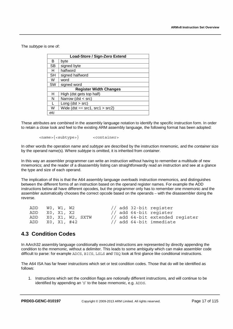
The subtype is one of:
Load-Store / Sign-Zero Extend B byte
SB signed byte H halfword
SH signed halfword W word
SW signed word Register Width Changes
H High (dst gets top half) N Narrow (dst < src) L Long (dst > src) W Wide (dst == src1, src1 > src2)
etc
These attributes are combined in the assembly language notation to identify the specific instruction form. In order to retain a close look and feel to the existing ARM assembly language, the following format has been adopted:
<name>{<subtype>} <container> In other words the operation name and subtype are described by the instruction mnemonic, and the container size by the operand name(s). Where subtype is omitted, it is inherited from container.
In this way an assembler programmer can write an instruction without having to remember a multitude of new mnemonics; and the reader of a disassembly listing can straightforwardly read an instruction and see at a glance the type and size of each operand.
The implication of this is that the A64 assembly language overloads instruction mnemonics, and distinguishes between the different forms of an instruction based on the operand register names. For example the ADD instructions below all have different opcodes, but the programmer only has to remember one mnemonic and the assembler automatically chooses the correct opcode based on the operands – with the disassembler doing the reverse.
ADD W0, W1, W2 // add 32-bit register ADD X0, X1, X2 // add 64-bit register ADD X0, X1, W2, SXTW // add 64-bit extended register ADD X0, X1, #42 // add 64-bit immediate
4.3 Condition Codes
In AArch32 assembly language conditionally executed instructions are represented by directly appending the condition to the mnemonic, without a delimiter. This leads to some ambiguity which can make assembler code difficult to parse: for example ADCS, BICS, LSLS and TEQ look at first glance like conditional instructions.
The A64 ISA has far fewer instructions which set or test condition codes. Those that do will be identified as follows:
1. Instructions which set the condition flags are notionally different instructions, and will continue to be identified by appending an ‘S’ to the base mnemonic, e.g. ADDS.

ARMv8 Instruction Set Overview
PRD03-GENC-010197 Copyright © 2009-2013 ARM Limited. All rights reserved. Page 18 of 115
2. Instructions which are truly conditionally executed (i.e. when the condition is false they have no effect on the architectural state, aside from advancing the program counter) have the condition appended to the instruction with a '.' delimiter. For example B.EQ.
3. If there is more than one instruction extension, then the conditional extension is always last. 4. Instructions which are unconditionally executed, but use the condition flags as a source operand, will
specify the condition to test in their final operand position, e.g. CSEL Wd,Wm,Wn,NE
To aid portability an A64 assembler may also provide the old UAL conditional mnemonics, so long as they have direct equivalents in the A64 ISA. However, the UAL mnemonics will not be generated by an A64 disassembler – their use is deprecated in 64-bit assembler code, and may cause a warning or error if backward compatibility is not explicitly requested by the programmer.
The full list of condition codes is as follows:
Encoding Name (& alias) Meaning (integer) Meaning (floating point) Flags
0000 EQ Equal Equal Z==1 0001 NE Not equal Not equal, or unordered Z==0
0010 HS (CS)
Unsigned higher or same (Carry set) Greater than, equal, or unordered C==1
0011 LO (CC)
Unsigned lower (Carry clear) Less than C==0
0100 MI Minus (negative) Less than N==1 0101 PL Plus (positive or zero) Greater than, equal, or unordered N==0 0110 VS Overflow set Unordered V==1 0111 VC Overflow clear Ordered V==0 1000 HI Unsigned higher Greater than, or unordered C==1 && Z==0 1001 LS Unsigned lower or same Less than or equal !(C==1 && Z==0)1010 GE Signed greater than or equal Greater than or equal N==V 1011 LT Signed less than Less than or unordered N!=V 1100 GT Signed greater than Greater than Z==0 && N==V 1101 LE Signed less than or equal Less than, equal, or unordered !(Z==0 && N==V)1110 AL 1111 NV†
Always Always Any
†The condition code NV exists only to provide a valid disassembly of the ‘1111b’ encoding, and otherwise behaves identically to AL.
ARMv8 Instruction Set Overview
PRD03-GENC-010197 Copyright © 2009-2013 ARM Limited. All rights reserved. Page 19 of 115
4.4 Register Names
4.4.1 General purpose (integer) registers
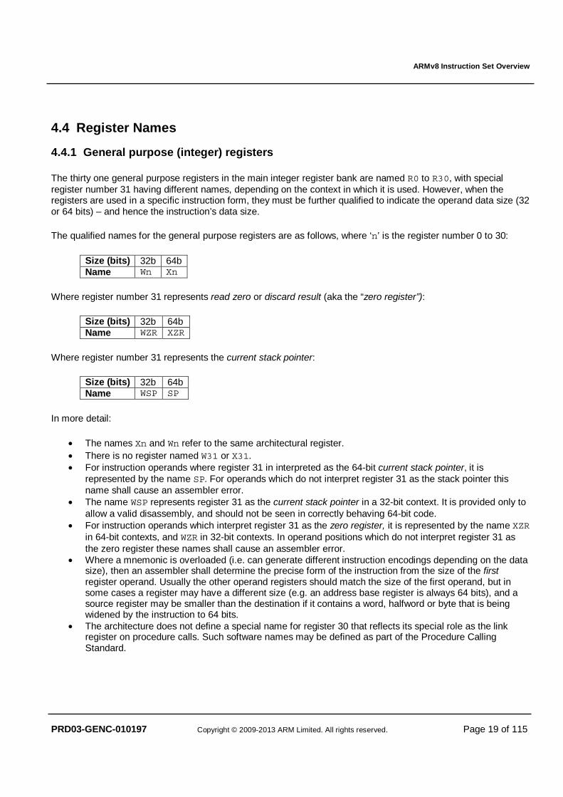
The thirty one general purpose registers in the main integer register bank are named R0 to R30, with special register number 31 having different names, depending on the context in which it is used. However, when the registers are used in a specific instruction form, they must be further qualified to indicate the operand data size (32 or 64 bits) – and hence the instruction’s data size.
The qualified names for the general purpose registers are as follows, where ‘n’ is the register number 0 to 30:
Size (bits) 32b 64b Name Wn Xn
Where register number 31 represents read zero or discard result (aka the “zero register”):
Size (bits) 32b 64b Name WZR XZR
Where register number 31 represents the current stack pointer:
Size (bits) 32b 64b Name WSP SP
In more detail:
• The names Xn and Wn refer to the same architectural register. • There is no register named W31 or X31. • For instruction operands where register 31 in interpreted as the 64-bit current stack pointer, it is
represented by the name SP. For operands which do not interpret register 31 as the stack pointer this name shall cause an assembler error.
• The name WSP represents register 31 as the current stack pointer in a 32-bit context. It is provided only to allow a valid disassembly, and should not be seen in correctly behaving 64-bit code.
• For instruction operands which interpret register 31 as the zero register, it is represented by the name XZR in 64-bit contexts, and WZR in 32-bit contexts. In operand positions which do not interpret register 31 as the zero register these names shall cause an assembler error.
• Where a mnemonic is overloaded (i.e. can generate different instruction encodings depending on the data size), then an assembler shall determine the precise form of the instruction from the size of the first register operand. Usually the other operand registers should match the size of the first operand, but in some cases a register may have a different size (e.g. an address base register is always 64 bits), and a source register may be smaller than the destination if it contains a word, halfword or byte that is being widened by the instruction to 64 bits.
• The architecture does not define a special name for register 30 that reflects its special role as the link register on procedure calls. Such software names may be defined as part of the Procedure Calling Standard.
ARMv8 Instruction Set Overview
PRD03-GENC-010197 Copyright © 2009-2013 ARM Limited. All rights reserved. Page 20 of 115
4.4.2 FP/SIMD registers
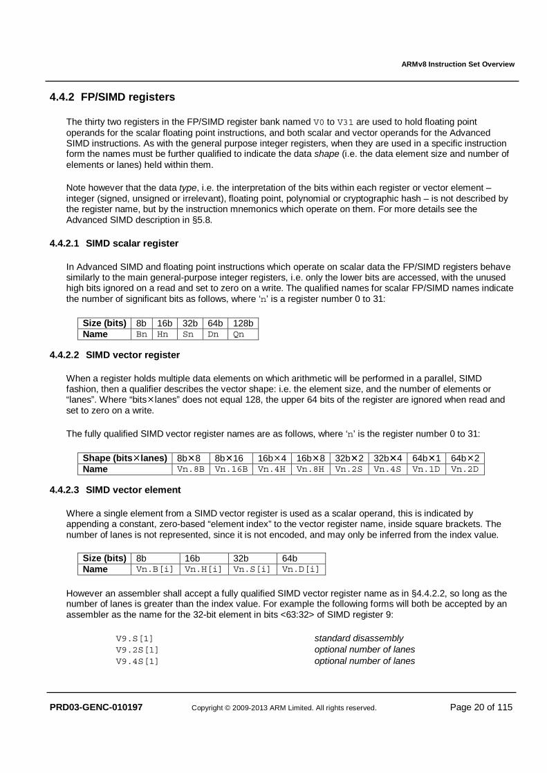
The thirty two registers in the FP/SIMD register bank named V0 to V31 are used to hold floating point operands for the scalar floating point instructions, and both scalar and vector operands for the Advanced SIMD instructions. As with the general purpose integer registers, when they are used in a specific instruction form the names must be further qualified to indicate the data shape (i.e. the data element size and number of elements or lanes) held within them.
Note however that the data type, i.e. the interpretation of the bits within each register or vector element – integer (signed, unsigned or irrelevant), floating point, polynomial or cryptographic hash – is not described by the register name, but by the instruction mnemonics which operate on them. For more details see the Advanced SIMD description in §5.8.
4.4.2.1 SIMD scalar register
In Advanced SIMD and floating point instructions which operate on scalar data the FP/SIMD registers behave similarly to the main general-purpose integer registers, i.e. only the lower bits are accessed, with the unused high bits ignored on a read and set to zero on a write. The qualified names for scalar FP/SIMD names indicate the number of significant bits as follows, where ‘n’ is a register number 0 to 31:
Size (bits) 8b 16b 32b 64b 128b Name Bn Hn Sn Dn Qn
4.4.2.2 SIMD vector register
When a register holds multiple data elements on which arithmetic will be performed in a parallel, SIMD fashion, then a qualifier describes the vector shape: i.e. the element size, and the number of elements or “lanes”. Where “bits�lanes” does not equal 128, the upper 64 bits of the register are ignored when read and set to zero on a write.
The fully qualified SIMD vector register names are as follows, where ‘n’ is the register number 0 to 31:
Shape (bits�lanes) 8b�8 8b�16 16b�4 16b�8 32b�2 32b�4 64b�1 64b�2 Name Vn.8B Vn.16B Vn.4H Vn.8H Vn.2S Vn.4S Vn.1D Vn.2D
4.4.2.3 SIMD vector element
Where a single element from a SIMD vector register is used as a scalar operand, this is indicated by appending a constant, zero-based “element index” to the vector register name, inside square brackets. The number of lanes is not represented, since it is not encoded, and may only be inferred from the index value.
Size (bits) 8b 16b 32b 64b Name Vn.B[i] Vn.H[i] Vn.S[i] Vn.D[i]
However an assembler shall accept a fully qualified SIMD vector register name as in §4.4.2.2, so long as the number of lanes is greater than the index value. For example the following forms will both be accepted by an assembler as the name for the 32-bit element in bits <63:32> of SIMD register 9:
V9.S[1] standard disassembly V9.2S[1] optional number of lanes V9.4S[1] optional number of lanes
ARMv8 Instruction Set Overview
PRD03-GENC-010197 Copyright © 2009-2013 ARM Limited. All rights reserved. Page 21 of 115
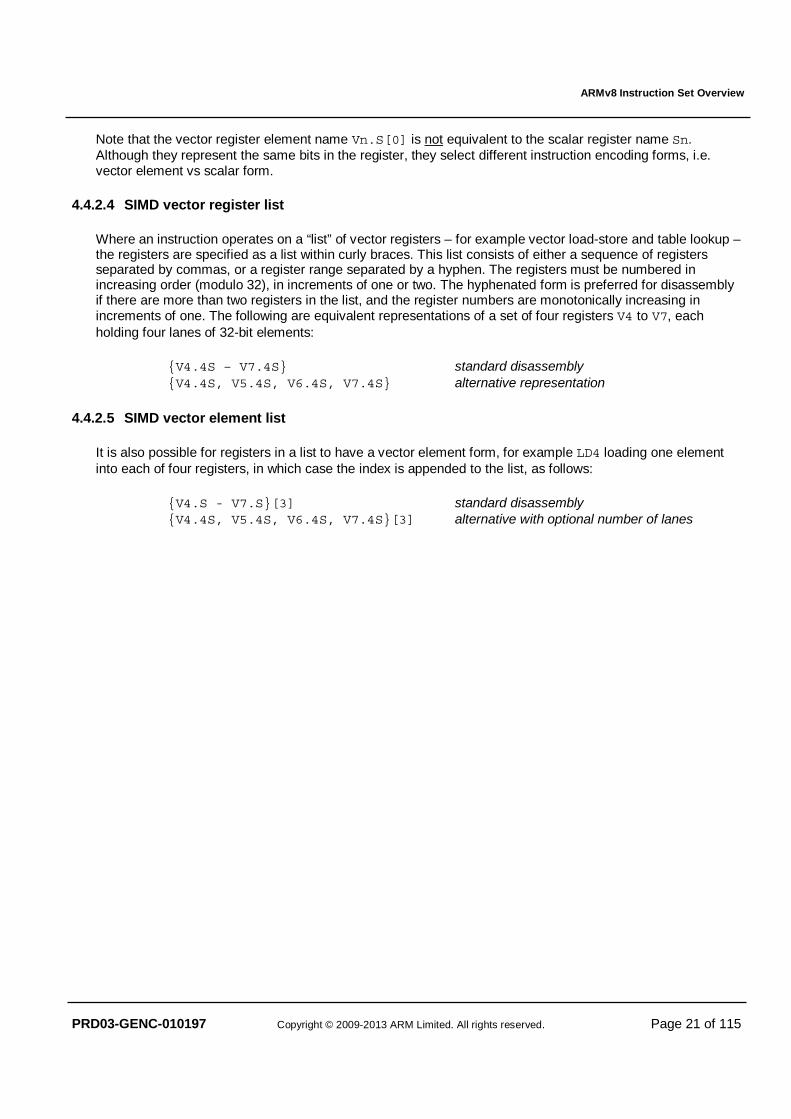
Note that the vector register element name Vn.S[0] is not equivalent to the scalar register name Sn. Although they represent the same bits in the register, they select different instruction encoding forms, i.e. vector element vs scalar form.
4.4.2.4 SIMD vector register list
Where an instruction operates on a “list” of vector registers – for example vector load-store and table lookup – the registers are specified as a list within curly braces. This list consists of either a sequence of registers separated by commas, or a register range separated by a hyphen. The registers must be numbered in increasing order (modulo 32), in increments of one or two. The hyphenated form is preferred for disassembly if there are more than two registers in the list, and the register numbers are monotonically increasing in increments of one. The following are equivalent representations of a set of four registers V4 to V7, each holding four lanes of 32-bit elements:
{V4.4S – V7.4S} standard disassembly {V4.4S, V5.4S, V6.4S, V7.4S} alternative representation
4.4.2.5 SIMD vector element list
It is also possible for registers in a list to have a vector element form, for example LD4 loading one element into each of four registers, in which case the index is appended to the list, as follows:
{V4.S - V7.S}[3] standard disassembly {V4.4S, V5.4S, V6.4S, V7.4S}[3] alternative with optional number of lanes
ARMv8 Instruction Set Overview
PRD03-GENC-010197 Copyright © 2009-2013 ARM Limited. All rights reserved. Page 22 of 115
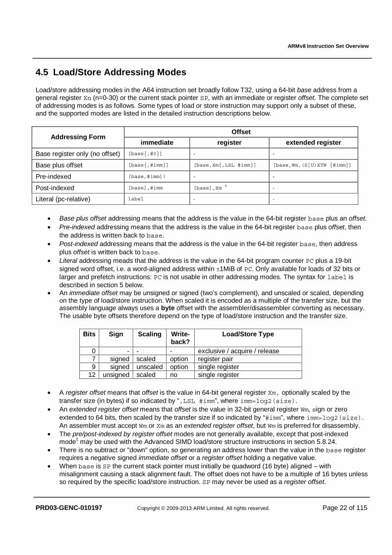
4.5 Load/Store Addressing Modes
Load/store addressing modes in the A64 instruction set broadly follow T32, using a 64-bit base address from a general register Xn (n=0-30) or the current stack pointer SP, with an immediate or register offset. The complete set of addressing modes is as follows. Some types of load or store instruction may support only a subset of these, and the supported modes are listed in the detailed instruction descriptions below.
Offset Addressing Form
immediate register extended register
Base register only (no offset) [base{,#0}] - -
Base plus offset [base{,#imm}] [base,Xm{,LSL #imm}] [base,Wm,(S|U)XTW {#imm}]
Pre-indexed [base,#imm]! - -
Post-indexed [base],#imm [base],Xm ‡ -
Literal (pc-relative) label - -
• Base plus offset addressing means that the address is the value in the 64-bit register base plus an offset. • Pre-indexed addressing means that the address is the value in the 64-bit register base plus offset, then
the address is written back to base. • Post-indexed addressing means that the address is the value in the 64-bit register base, then address
plus offset is written back to base. • Literal addressing meads that the address is the value in the 64-bit program counter PC plus a 19-bit
signed word offset, i.e. a word-aligned address within ±1MiB of PC. Only available for loads of 32 bits or larger and prefetch instructions: PC is not usable in other addressing modes. The syntax for label is described in section 5 below.
• An immediate offset may be unsigned or signed (two’s complement), and unscaled or scaled, depending on the type of load/store instruction. When scaled it is encoded as a multiple of the transfer size, but the assembly language always uses a byte offset with the assembler/disassembler converting as necessary. The usable byte offsets therefore depend on the type of load/store instruction and the transfer size.
Bits Sign Scaling Write-back?
Load/Store Type
0 - - - exclusive / acquire / release 7 signed scaled option register pair 9 signed unscaled option single register
12 unsigned scaled no single register
• A register offset means that offset is the value in 64-bit general register Xm, optionally scaled by the transfer size (in bytes) if so indicated by “,LSL #imm”, where imm=log2(size).
• An extended register offset means that offset is the value in 32-bit general register Wm, sign or zero extended to 64 bits, then scaled by the transfer size if so indicated by “#imm”, where imm=log2(size). An assembler must accept Wm or Xm as an extended register offset, but Wm is preferred for disassembly.
• The pre/post-indexed by register offset modes are not generally available, except that post-indexed mode‡ may be used with the Advanced SIMD load/store structure instructions in section 5.8.24.
• There is no subtract or "down" option, so generating an address lower than the value in the base register requires a negative signed immediate offset or a register offset holding a negative value.
• When base is SP the current stack pointer must initially be quadword (16 byte) aligned – with misalignment causing a stack alignment fault. The offset does not have to be a multiple of 16 bytes unless so required by the specific load/store instruction. SP may never be used as a register offset.
ARMv8 Instruction Set Overview
PRD03-GENC-010197 Copyright © 2009-2013 ARM Limited. All rights reserved. Page 23 of 115
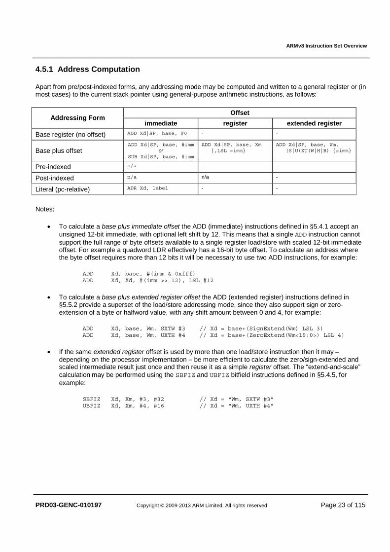
4.5.1 Address Computation
Apart from pre/post-indexed forms, any addressing mode may be computed and written to a general register or (in most cases) to the current stack pointer using general-purpose arithmetic instructions, as follows:
Offset Addressing Form
immediate register extended register
Base register (no offset) ADD Xd|SP, base, #0 - -
Base plus offset ADD Xd|SP, base, #imm
or SUB Xd|SP, base, #imm
ADD Xd|SP, base, Xm {,LSL #imm}
ADD Xd|SP, base, Wm, (S|U)XT(W|H|B) {#imm}
Pre-indexed n/a - -
Post-indexed n/a n/a -
Literal (pc-relative) ADR Xd, label - -
Notes:
• To calculate a base plus immediate offset the ADD (immediate) instructions defined in §5.4.1 accept an unsigned 12-bit immediate, with optional left shift by 12. This means that a single ADD instruction cannot support the full range of byte offsets available to a single register load/store with scaled 12-bit immediate offset. For example a quadword LDR effectively has a 16-bit byte offset. To calculate an address where the byte offset requires more than 12 bits it will be necessary to use two ADD instructions, for example:
ADD Xd, base, #(imm & 0xfff) ADD Xd, Xd, #(imm >> 12), LSL #12
• To calculate a base plus extended register offset the ADD (extended register) instructions defined in §5.5.2 provide a superset of the load/store addressing mode, since they also support sign or zero-extension of a byte or halfword value, with any shift amount between 0 and 4, for example:
ADD Xd, base, Wm, SXTW #3 // Xd = base+(SignExtend(Wm) LSL 3) ADD Xd, base, Wm, UXTH #4 // Xd = base+(ZeroExtend(Wm<15:0>) LSL 4)
• If the same extended register offset is used by more than one load/store instruction then it may – depending on the processor implementation – be more efficient to calculate the zero/sign-extended and scaled intermediate result just once and then reuse it as a simple register offset. The “extend-and-scale” calculation may be performed using the SBFIZ and UBFIZ bitfield instructions defined in §5.4.5, for example:
SBFIZ Xd, Xm, #3, #32 // Xd = “Wm, SXTW #3” UBFIZ Xd, Xm, #4, #16 // Xd = “Wm, UXTH #4”
ARMv8 Instruction Set Overview
PRD03-GENC-010197 Copyright © 2009-2013 ARM Limited. All rights reserved. Page 24 of 115
5 A64 INSTRUCTION SET
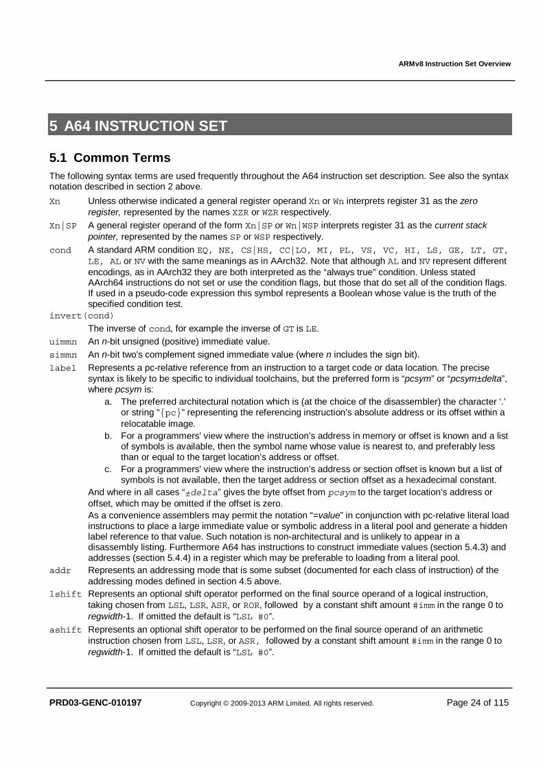
5.1 Common Terms The following syntax terms are used frequently throughout the A64 instruction set description. See also the syntax notation described in section 2 above.
Xn Unless otherwise indicated a general register operand Xn or Wn interprets register 31 as the zero register, represented by the names XZR or WZR respectively.
Xn|SP A general register operand of the form Xn|SP or Wn|WSP interprets register 31 as the current stack pointer, represented by the names SP or WSP respectively.
cond A standard ARM condition EQ, NE, CS|HS, CC|LO, MI, PL, VS, VC, HI, LS, GE, LT, GT, LE, AL or NV with the same meanings as in AArch32. Note that although AL and NV represent different encodings, as in AArch32 they are both interpreted as the “always true” condition. Unless stated AArch64 instructions do not set or use the condition flags, but those that do set all of the condition flags. If used in a pseudo-code expression this symbol represents a Boolean whose value is the truth of the specified condition test.
invert(cond)
The inverse of cond, for example the inverse of GT is LE. uimmn An n-bit unsigned (positive) immediate value. simmn An n-bit two's complement signed immediate value (where n includes the sign bit). label Represents a pc-relative reference from an instruction to a target code or data location. The precise
syntax is likely to be specific to individual toolchains, but the preferred form is “pcsym” or “pcsym±delta”, where pcsym is:
a. The preferred architectural notation which is (at the choice of the disassembler) the character ‘.’ or string “{pc}” representing the referencing instruction’s absolute address or its offset within a relocatable image.
b. For a programmers’ view where the instruction’s address in memory or offset is known and a list of symbols is available, then the symbol name whose value is nearest to, and preferably less than or equal to the target location’s address or offset.
c. For a programmers’ view where the instruction’s address or section offset is known but a list of symbols is not available, then the target address or section offset as a hexadecimal constant.
And where in all cases “±delta” gives the byte offset from pcsym to the target location’s address or offset, which may be omitted if the offset is zero.
As a convenience assemblers may permit the notation “=value” in conjunction with pc-relative literal load instructions to place a large immediate value or symbolic address in a literal pool and generate a hidden label reference to that value. Such notation is non-architectural and is unlikely to appear in a disassembly listing. Furthermore A64 has instructions to construct immediate values (section 5.4.3) and addresses (section 5.4.4) in a register which may be preferable to loading from a literal pool.
addr Represents an addressing mode that is some subset (documented for each class of instruction) of the addressing modes defined in section 4.5 above.
lshift Represents an optional shift operator performed on the final source operand of a logical instruction, taking chosen from LSL, LSR, ASR, or ROR, followed by a constant shift amount #imm in the range 0 to regwidth-1. If omitted the default is “LSL #0”.
ashift Represents an optional shift operator to be performed on the final source operand of an arithmetic instruction chosen from LSL, LSR, or ASR, followed by a constant shift amount #imm in the range 0 to regwidth-1. If omitted the default is “LSL #0”.
ARMv8 Instruction Set Overview
PRD03-GENC-010197 Copyright © 2009-2013 ARM Limited. All rights reserved. Page 25 of 115
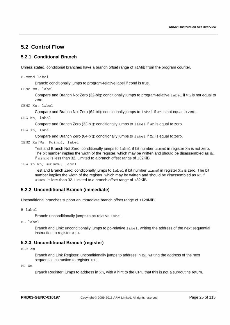
5.2 Control Flow
5.2.1 Conditional Branch
Unless stated, conditional branches have a branch offset range of ±1MiB from the program counter.
B.cond label
Branch: conditionally jumps to program-relative label if cond is true.
CBNZ Wn, label
Compare and Branch Not Zero (32-bit): conditionally jumps to program-relative label if Wn is not equal to zero.
CBNZ Xn, label
Compare and Branch Not Zero (64-bit): conditionally jumps to label if Xn is not equal to zero.
CBZ Wn, label
Compare and Branch Zero (32-bit): conditionally jumps to label if Wn is equal to zero.
CBZ Xn, label
Compare and Branch Zero (64-bit): conditionally jumps to label if Xn is equal to zero.
TBNZ Xn|Wn, #uimm6, label
Test and Branch Not Zero: conditionally jumps to label if bit number uimm6 in register Xn is not zero. The bit number implies the width of the register, which may be written and should be disassembled as Wn if uimm6 is less than 32. Limited to a branch offset range of ±32KiB.
TBZ Xn|Wn, #uimm6, label
Test and Branch Zero: conditionally jumps to label if bit number uimm6 in register Xn is zero. The bit number implies the width of the register, which may be written and should be disassembled as Wn if uimm6 is less than 32. Limited to a branch offset range of ±32KiB.
5.2.2 Unconditional Branch (immediate)
Unconditional branches support an immediate branch offset range of ±128MiB.
B label Branch: unconditionally jumps to pc-relative label.
BL label Branch and Link: unconditionally jumps to pc-relative label, writing the address of the next sequential instruction to register X30.
5.2.3 Unconditional Branch (register) BLR Xm
Branch and Link Register: unconditionally jumps to address in Xm, writing the address of the next sequential instruction to register X30.
BR Xm
Branch Register: jumps to address in Xm, with a hint to the CPU that this is not a subroutine return.
ARMv8 Instruction Set Overview
PRD03-GENC-010197 Copyright © 2009-2013 ARM Limited. All rights reserved. Page 26 of 115
RET {Xm}
Return: jumps to register Xm, with a hint to the CPU that this is a subroutine return. An assembler shall default to register X30 if Xm is omitted.
5.3 Memory Access Aside from exclusive and explicitly ordered loads and stores, addresses may have arbitrary alignment unless strict alignment checking is enabled (SCTLR.A==1). However if SP is used as the base register then the value of the current stack pointer prior to adding any offset must be quadword (16 byte) aligned, or else a stack alignment exception will be generated.
A memory read or write generated by the load or store of a single general-purpose register aligned to the size of the transfer is atomic. Memory reads or writes generated by the non-exclusive load or store of a pair of general-purpose registers aligned to the size of the register are treated as two atomic accesses, one for each register. In all other cases, unless otherwise stated, there are no atomicity guarantees.
5.3.1 Load-Store Single Register Addressing modes supported by addr (referring to §4.5):
• Base plus immediate offset (scaled 12-bit unsigned, unscaled 9-bit signed); • Base plus 64-bit register offset (optionally scaled); • Base plus 32-bit extended register offset (optionally scaled); • Pre-indexed by immediate offset (unscaled 9-bit signed); • Post-indexed by immediate offset (unscaled 9-bit signed); • Literal (pc-relative), for loads of 32-bits or larger.
If a Load instruction specifies writeback and the register being loaded is also the base register, then one of the following behaviours can occur:
• The instruction is UNALLOCATED
• The instruction is treated as a NOP
• The instruction performs the load using the specified addressing mode and the base register becomes UNKNOWN. In addition, if an exception occurs during such an instruction, the base address might be corrupted such that the instruction cannot be repeated.
If a Store instruction performs a writeback and the register being stored is also the base register, then one of the following behaviours can occur:
• The instruction is UNALLOCATED
• The instruction is treated as a NOP
• The instruction performs the stores of the register specified using the specified addressing mode but the value stored is UNKNOWN
LDR Wt, addr
Load Register (32-bit): loads a word from memory addressed by addr to Wt.
LDR Xt, addr
Load Register (64-bit): loads a doubleword from memory addressed by addr to Xt.
LDRB Wt, addr
Load Byte: loads a byte from memory addressed by addr, then zero-extends it to Wt.
LDRSB Wt, addr
Load Signed Byte (32-bit): loads a byte from memory addressed by addr, then sign-extends it into Wt.
ARMv8 Instruction Set Overview
PRD03-GENC-010197 Copyright © 2009-2013 ARM Limited. All rights reserved. Page 27 of 115
LDRSB Xt, addr
Load Signed Byte (64-bit): loads a byte from memory addressed by addr, then sign-extends it into Xt.
LDRH Wt, addr
Load Halfword: loads a halfword from memory addressed by addr, then zero-extends it into Wt.
LDRSH Wt, addr
Load Signed Halfword (32-bit): loads a halfword from memory addressed by addr, then sign-extends it into Wt.
LDRSH Xt, addr
Load Signed Halfword (64-bit): loads a halfword from memory addressed by addr, then sign-extends it into Xt.
LDRSW Xt, addr
Load Signed Word: loads a word from memory addressed by addr, then sign-extends it into Xt.
STR Wt, addr
Store Register (32-bit): stores word from Wt to memory addressed by addr.
STR Xt, addr
Store Register (64-bit): stores doubleword from Xt to memory addressed by addr.
STRB Wt, addr
Store Byte: stores byte from Wt to memory addressed by addr.
STRH Wt, addr
Store Halfword: stores halfword from Wt to memory addressed by addr.
5.3.2 Load-Store Single Register (unscaled offset) Addressing modes supported (referring to §4.5):
• Base plus immediate offset (unscaled 9-bit signed).
These mnemonics distinguish instructions which use this form of offset when the byte offset value could also be represented by instructions which use the scaled 12-bit unsigned immediate offset form, i.e. when its value is positive and naturally aligned to the transfer size.
A programmer-friendly assembler should also generate these instructions in response to the standard LDR/STR mnemonics when the immediate offset is unambiguous, i.e. negative or unaligned. A disassembler could also display these instructions using the standard LDR/STR mnemonics when the encoded immediate is unambiguous, however that is not required by the architectural assembly language.
LDUR Wt, [base,#simm9]
Load (Unscaled) Register (32-bit): loads a word from memory addressed by base+simm9 to Wt.
LDUR Xt, [base,#simm9]
Load (Unscaled) Register (64-bit): loads a doubleword from memory addressed by base+simm9 to Xt.
LDURB Wt, [base,#simm9]
Load (Unscaled) Byte: loads a byte from memory addressed by base+simm9, then zero-extends it into Wt.
LDURSB Wt, [base,#simm9]
Load (Unscaled) Signed Byte (32-bit): loads a byte from memory addressed by base+simm9, then sign-extends it into Wt.
ARMv8 Instruction Set Overview
PRD03-GENC-010197 Copyright © 2009-2013 ARM Limited. All rights reserved. Page 28 of 115
LDURSB Xt, [base,#simm9]
Load (Unscaled) Signed Byte (64-bit): loads a byte from memory addressed by base+simm9, then sign-extends it into Xt.
LDURH Wt, [base,#simm9]
Load (Unscaled) Halfword: loads a halfword from memory addressed by base+simm9, then zero-extends it into Wt.
LDURSH Wt, [base,#simm9]
Load (Unscaled) Signed Halfword (32-bit): loads a halfword from memory addressed by base+simm9, then sign-extends it into Wt.
LDURSH Xt, [base,#simm9]
Load (Unscaled) Signed Halfword (64-bit): loads a halfword from memory addressed by base+simm9, then sign-extends it into Xt.
LDURSW Xt, [base,#simm9]
Load (Unscaled) Signed Word: loads a word from memory addressed by base+simm9, then sign-extends it into Xt.
STUR Wt, [base,#simm9]
Store (Unscaled) Register (32-bit): stores word from Wt to memory addressed by base+simm9.
STUR Xt, [base,#simm9]
Store (Unscaled) Register (64-bit): stores doubleword from Xt to memory addressed by base+simm9.
STURB Wt, [base,#simm9]
Store (Unscaled) Byte: stores byte from Wt to memory addressed by base+simm9.
STURH Wt, [base,#simm9]
Store (Unscaled) Halfword: stores halfword from Wt to memory addressed by base+simm9.
5.3.3 Load-Store Pair Addressing modes supported by addr (referring to §4.5):
• Base plus immediate offset (scaled 7-bit signed); • Pre-indexed by immediate offset (scaled 7-bit signed); • Post-indexed by immediate offset (scaled 7-bit signed).
If a Load Pair instruction specifies the same register for the two registers that are being loaded, then one of the following behaviours can occur:
• The instruction is UNALLOCATED
• The instruction is treated as a NOP
• The instruction performs all of the loads using the specified addressing mode and the register being loaded takes an UNKNOWN value
If a Load Pair instruction specifies writeback and one of the registers being loaded is also the base register, then one of the following behaviours can occur:
• The instruction is UNALLOCATED
• The instruction is treated as a NOP
• The instruction performs all of the loads using the specified addressing mode and the base register becomes UNKNOWN. In addition, if an exception occurs during such an instruction, the base address might be corrupted such that the instruction cannot be repeated.
ARMv8 Instruction Set Overview
PRD03-GENC-010197 Copyright © 2009-2013 ARM Limited. All rights reserved. Page 29 of 115
If a Store Pair instruction performs a writeback and one of the registers being stored is also the base register, then one of the following behaviours can occur:
• The instruction is UNALLOCATED
• The instruction is treated as a NOP
• The instruction performs all of the stores of the registers specified using the specified addressing mode but the value stored for the base register is UNKNOWN
LDP Wt1, Wt2, addr
Load Pair (32-bit): loads two words from memory addressed by addr to Wt1 and Wt2.
LDP Xt1, Xt2, addr
Load Pair (64-bit): loads two doublewords from memory addressed by addr to Xt1 and Xt2.
LDPSW Xt1, Xt2, addr
Load Pair Signed Words: loads two words from memory addressed by addr, then sign-extends them into Xt1 and Xt2.
STP Wt1, Wt2, addr
Store Pair (32-bit): stores two words from Wt1 and Wt2 to memory addressed by addr.
STP Xt1, Xt2, addr
Store Pair (64-bit): stores two doublewords from Xt1 and Xt2 to memory addressed by addr.
5.3.4 Load-Store Non-temporal Pair Addressing modes supported (referring to §4.5):
• Base plus immediate offset (scaled 7-bit signed);
The load-store non-temporal pair instructions provide a hint to the memory system that an access is “non-temporal” or “streaming” and unlikely to be accessed again in the near future so need not be retained in data caches. However depending on the memory type they may permit memory reads to be preloaded and memory writes to be gathered, in order to accelerate bulk memory transfers.
Furthermore, as a special exception to the normal memory ordering rules, where an address dependency exists between two memory reads and the second read was generated by a Load Non-temporal Pair instruction then, in the absence of any other barrier mechanism to achieve order, those memory accesses can be observed in any order by other observers within the shareability domain of the memory addresses being accessed.
If a Load Non-temporal Pair instruction specifies the same register for the two registers that are being loaded, then one of the following behaviours can occur:
• The instruction is UNALLOCATED
• The instruction is treated as a NOP
• The instruction performs all of the loads using the specified addressing mode and the register being loaded takes an UNKNOWN value
LDNP Wt1, Wt2, [base,#imm]
Load Non-temporal Pair (32-bit): loads two words from memory addressed by base+imm to Wt1 and Wt2, with a non-temporal hint.
LDNP Xt1, Xt2, [base,#imm]
Load Non-temporal Pair (64-bit): loads two doublewords from memory addressed by base+imm to Xt1 and Xt2, with a non-temporal hint.
ARMv8 Instruction Set Overview
PRD03-GENC-010197 Copyright © 2009-2013 ARM Limited. All rights reserved. Page 30 of 115
STNP Wt1, Wt2, [base,#imm]
Store Non-temporal Pair (32-bit): stores two words from Wt1 and Wt2 to memory addressed by base+imm, with a non-temporal hint.
STNP Xt1, Xt2, [base,#imm]
Store Non-temporal Pair (64-bit): stores two doublewords from Xt1 and Xt2 to memory addressed by base+imm, with a non-temporal hint.
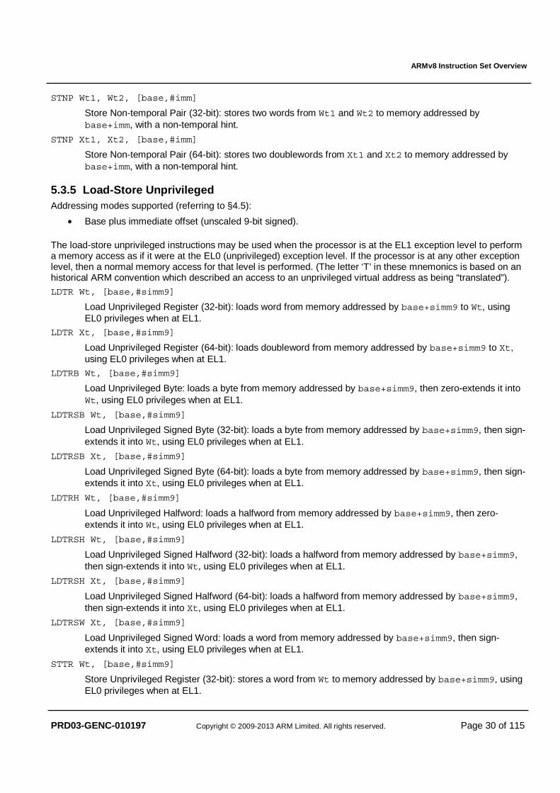
5.3.5 Load-Store Unprivileged Addressing modes supported (referring to §4.5):
• Base plus immediate offset (unscaled 9-bit signed).
The load-store unprivileged instructions may be used when the processor is at the EL1 exception level to perform a memory access as if it were at the EL0 (unprivileged) exception level. If the processor is at any other exception level, then a normal memory access for that level is performed. (The letter ‘T’ in these mnemonics is based on an historical ARM convention which described an access to an unprivileged virtual address as being “translated”).
LDTR Wt, [base,#simm9]
Load Unprivileged Register (32-bit): loads word from memory addressed by base+simm9 to Wt, using EL0 privileges when at EL1.
LDTR Xt, [base,#simm9]
Load Unprivileged Register (64-bit): loads doubleword from memory addressed by base+simm9 to Xt, using EL0 privileges when at EL1.
LDTRB Wt, [base,#simm9]
Load Unprivileged Byte: loads a byte from memory addressed by base+simm9, then zero-extends it into Wt, using EL0 privileges when at EL1.
LDTRSB Wt, [base,#simm9]
Load Unprivileged Signed Byte (32-bit): loads a byte from memory addressed by base+simm9, then sign-extends it into Wt, using EL0 privileges when at EL1.
LDTRSB Xt, [base,#simm9]
Load Unprivileged Signed Byte (64-bit): loads a byte from memory addressed by base+simm9, then sign-extends it into Xt, using EL0 privileges when at EL1.
LDTRH Wt, [base,#simm9]
Load Unprivileged Halfword: loads a halfword from memory addressed by base+simm9, then zero-extends it into Wt, using EL0 privileges when at EL1.
LDTRSH Wt, [base,#simm9]
Load Unprivileged Signed Halfword (32-bit): loads a halfword from memory addressed by base+simm9, then sign-extends it into Wt, using EL0 privileges when at EL1.
LDTRSH Xt, [base,#simm9]
Load Unprivileged Signed Halfword (64-bit): loads a halfword from memory addressed by base+simm9, then sign-extends it into Xt, using EL0 privileges when at EL1.
LDTRSW Xt, [base,#simm9]
Load Unprivileged Signed Word: loads a word from memory addressed by base+simm9, then sign-extends it into Xt, using EL0 privileges when at EL1.
STTR Wt, [base,#simm9]
Store Unprivileged Register (32-bit): stores a word from Wt to memory addressed by base+simm9, using EL0 privileges when at EL1.
ARMv8 Instruction Set Overview
PRD03-GENC-010197 Copyright © 2009-2013 ARM Limited. All rights reserved. Page 31 of 115
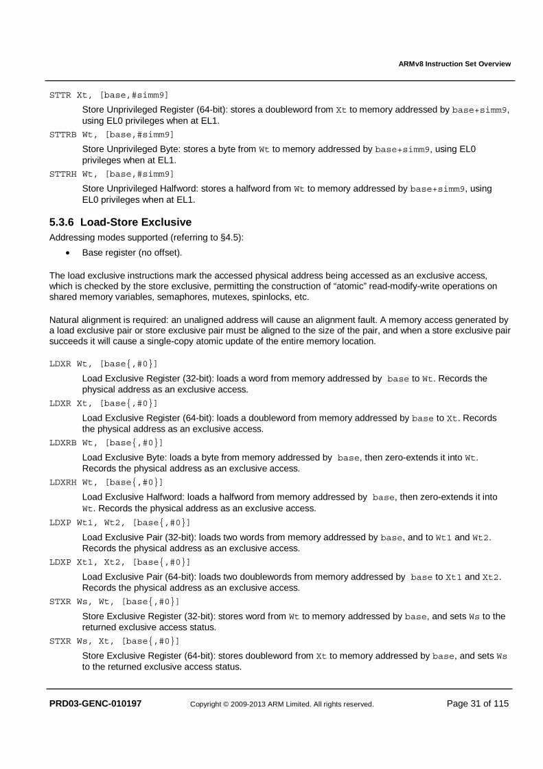
STTR Xt, [base,#simm9]
Store Unprivileged Register (64-bit): stores a doubleword from Xt to memory addressed by base+simm9, using EL0 privileges when at EL1.
STTRB Wt, [base,#simm9]
Store Unprivileged Byte: stores a byte from Wt to memory addressed by base+simm9, using EL0 privileges when at EL1.
STTRH Wt, [base,#simm9]
Store Unprivileged Halfword: stores a halfword from Wt to memory addressed by base+simm9, using EL0 privileges when at EL1.
5.3.6 Load-Store Exclusive Addressing modes supported (referring to §4.5):
• Base register (no offset).
The load exclusive instructions mark the accessed physical address being accessed as an exclusive access, which is checked by the store exclusive, permitting the construction of “atomic” read-modify-write operations on shared memory variables, semaphores, mutexes, spinlocks, etc.
Natural alignment is required: an unaligned address will cause an alignment fault. A memory access generated by a load exclusive pair or store exclusive pair must be aligned to the size of the pair, and when a store exclusive pair succeeds it will cause a single-copy atomic update of the entire memory location.
LDXR Wt, [base{,#0}]
Load Exclusive Register (32-bit): loads a word from memory addressed by base to Wt. Records the physical address as an exclusive access.
LDXR Xt, [base{,#0}]
Load Exclusive Register (64-bit): loads a doubleword from memory addressed by base to Xt. Records the physical address as an exclusive access.
LDXRB Wt, [base{,#0}]
Load Exclusive Byte: loads a byte from memory addressed by base, then zero-extends it into Wt. Records the physical address as an exclusive access.
LDXRH Wt, [base{,#0}]
Load Exclusive Halfword: loads a halfword from memory addressed by base, then zero-extends it into Wt. Records the physical address as an exclusive access.
LDXP Wt1, Wt2, [base{,#0}]
Load Exclusive Pair (32-bit): loads two words from memory addressed by base, and to Wt1 and Wt2. Records the physical address as an exclusive access.
LDXP Xt1, Xt2, [base{,#0}]
Load Exclusive Pair (64-bit): loads two doublewords from memory addressed by base to Xt1 and Xt2. Records the physical address as an exclusive access.
STXR Ws, Wt, [base{,#0}]
Store Exclusive Register (32-bit): stores word from Wt to memory addressed by base, and sets Ws to the returned exclusive access status.
STXR Ws, Xt, [base{,#0}]
Store Exclusive Register (64-bit): stores doubleword from Xt to memory addressed by base, and sets Ws to the returned exclusive access status.

ARMv8 Instruction Set Overview
PRD03-GENC-010197 Copyright © 2009-2013 ARM Limited. All rights reserved. Page 32 of 115
STXRB Ws, Wt, [base{,#0}]
Store Exclusive Byte: stores byte from Wt to memory addressed by base, and sets Ws to the returned exclusive access status.
STXRH Ws, Wt, [base{,#0}]
Store Exclusive Halfword: stores halfword from Xt to memory addressed by base, and sets Ws to the returned exclusive access status.
STXP Ws, Wt1, Wt2, [base{,#0}]
Store Exclusive Pair (32-bit): stores two words from Wt1 and Wt2 to memory addressed by base, and sets Ws to the returned exclusive access status.
STXP Ws, Xt1, Xt2, [base{,#0}]
Store Exclusive Pair (64-bit): stores two doublewords from Xt1 and Xt2 to memory addressed by base, and sets Ws to the returned exclusive access status.
5.3.7 Load-Acquire / Store-Release Addressing modes supported (referring to §4.5):
• Base register (no offset).
A load-acquire is a load where it is guaranteed that all loads and stores appearing in program order after the load-acquire will be observed by each observer after that observer observes the load-acquire, but says nothing about loads and stores appearing before the load-acquire.
A store-release will be observed by each observer after that observer observes any loads or stores that appear in program order before the store-release, but says nothing about loads and stores appearing after the store-release.
In addition, a store-release followed by a load-acquire will be observed by each observer in program order.
A further consideration is that all store-release operations are multi-copy atomic when observed by load-acquire: that is, if one observer has seen a store-release, then all observers have seen the store-release. There are no requirements for ordinary stores to be multi-copy atomic. The load-acquire and store-release instructions can in many cases remove the need to use the explicit DMB memory barrier instructions described in section 5.9.5.
Load-acquire or store-release of a pair of registers may only be achieved using an atomic sequence of LDAXP and STLXP, testing the store status. There are deliberately no LDAP and STLP instructions since ordering cannot be enforced relative to a non-atomic pair of accesses.
Natural alignment is required: an unaligned address will cause an alignment fault.
5.3.7.1 Non-exclusive LDAR Wt, [base{,#0}]
Load-Acquire Register (32-bit): loads a word from memory addressed by base to Wt.
LDAR Xt, [base{,#0}]
Load-Acquire Register (64-bit): loads a doubleword from memory addressed by base to Xt.
LDARB Wt, [base{,#0}]
Load-Acquire Byte: loads a byte from memory addressed by base, then zero-extends it into Wt.
LDARH Wt, [base{,#0}]
Load-Acquire Halfword: loads a halfword from memory addressed by base, then zero-extends it into Wt.
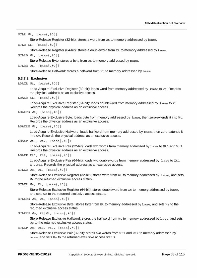
ARMv8 Instruction Set Overview
PRD03-GENC-010197 Copyright © 2009-2013 ARM Limited. All rights reserved. Page 33 of 115
STLR Wt, [base{,#0}]
Store-Release Register (32-bit): stores a word from Wt to memory addressed by base.
STLR Xt, [base{,#0}]
Store-Release Register (64-bit): stores a doubleword from Xt to memory addressed by base.
STLRB Wt, [base{,#0}]
Store-Release Byte: stores a byte from Wt to memory addressed by base.
STLRH Wt, [base{,#0}]
Store-Release Halfword: stores a halfword from Wt to memory addressed by base.
5.3.7.2 Exclusive LDAXR Wt, [base{,#0}]
Load-Acquire Exclusive Register (32-bit): loads word from memory addressed by base to Wt. Records the physical address as an exclusive access.
LDAXR Xt, [base{,#0}]
Load-Acquire Exclusive Register (64-bit): loads doubleword from memory addressed by base to Xt. Records the physical address as an exclusive access.
LDAXRB Wt, [base{,#0}]
Load-Acquire Exclusive Byte: loads byte from memory addressed by base, then zero-extends it into Wt. Records the physical address as an exclusive access.
LDAXRH Wt, [base{,#0}]
Load-Acquire Exclusive Halfword: loads halfword from memory addressed by base, then zero-extends it into Wt. Records the physical address as an exclusive access.
LDAXP Wt1, Wt2, [base{,#0}]
Load-Acquire Exclusive Pair (32-bit): loads two words from memory addressed by base to Wt1 and Wt2. Records the physical address as an exclusive access.
LDAXP Xt1, Xt2, [base{,#0}]
Load-Acquire Exclusive Pair (64-bit): loads two doublewords from memory addressed by base to Xt1 and Xt2. Records the physical address as an exclusive access.
STLXR Ws, Wt, [base{,#0}]
Store-Release Exclusive Register (32-bit): stores word from Wt to memory addressed by base, and sets Ws to the returned exclusive access status.
STLXR Ws, Xt, [base{,#0}]
Store-Release Exclusive Register (64-bit): stores doubleword from Xt to memory addressed by base, and sets Ws to the returned exclusive access status.
STLXRB Ws, Wt, [base{,#0}]
Store-Release Exclusive Byte: stores byte from Wt to memory addressed by base, and sets Ws to the returned exclusive access status.
STLXRH Ws, Xt|Wt, [base{,#0}]
Store-Release Exclusive Halfword: stores the halfword from Wt to memory addressed by base, and sets Ws to the returned exclusive access status.
STLXP Ws, Wt1, Wt2, [base{,#0}]
Store-Release Exclusive Pair (32-bit): stores two words from Wt1 and Wt2 to memory addressed by base, and sets Ws to the returned exclusive access status.
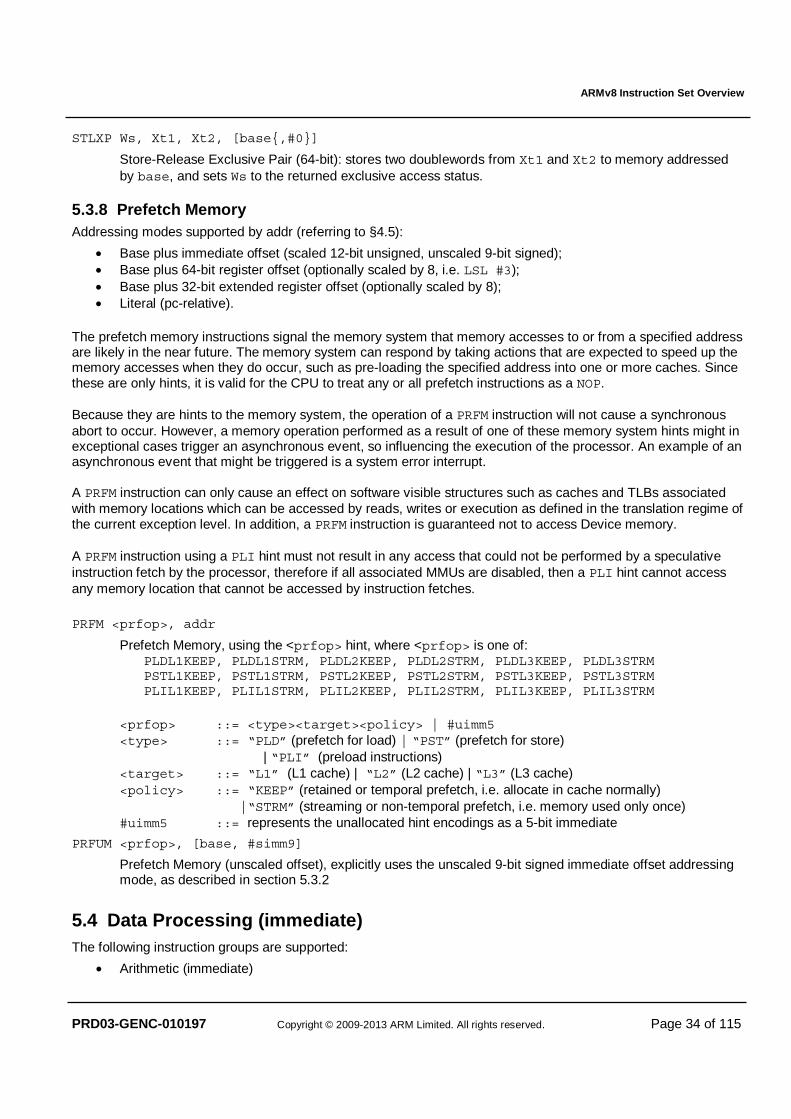
ARMv8 Instruction Set Overview
PRD03-GENC-010197 Copyright © 2009-2013 ARM Limited. All rights reserved. Page 34 of 115
STLXP Ws, Xt1, Xt2, [base{,#0}]
Store-Release Exclusive Pair (64-bit): stores two doublewords from Xt1 and Xt2 to memory addressed by base, and sets Ws to the returned exclusive access status.
5.3.8 Prefetch Memory Addressing modes supported by addr (referring to §4.5):
• Base plus immediate offset (scaled 12-bit unsigned, unscaled 9-bit signed); • Base plus 64-bit register offset (optionally scaled by 8, i.e. LSL #3); • Base plus 32-bit extended register offset (optionally scaled by 8); • Literal (pc-relative).
The prefetch memory instructions signal the memory system that memory accesses to or from a specified address are likely in the near future. The memory system can respond by taking actions that are expected to speed up the memory accesses when they do occur, such as pre-loading the specified address into one or more caches. Since these are only hints, it is valid for the CPU to treat any or all prefetch instructions as a NOP. Because they are hints to the memory system, the operation of a PRFM instruction will not cause a synchronous abort to occur. However, a memory operation performed as a result of one of these memory system hints might in exceptional cases trigger an asynchronous event, so influencing the execution of the processor. An example of an asynchronous event that might be triggered is a system error interrupt. A PRFM instruction can only cause an effect on software visible structures such as caches and TLBs associated with memory locations which can be accessed by reads, writes or execution as defined in the translation regime of the current exception level. In addition, a PRFM instruction is guaranteed not to access Device memory. A PRFM instruction using a PLI hint must not result in any access that could not be performed by a speculative instruction fetch by the processor, therefore if all associated MMUs are disabled, then a PLI hint cannot access any memory location that cannot be accessed by instruction fetches.
PRFM <prfop>, addr
Prefetch Memory, using the <prfop> hint, where <prfop> is one of: PLDL1KEEP, PLDL1STRM, PLDL2KEEP, PLDL2STRM, PLDL3KEEP, PLDL3STRM PSTL1KEEP, PSTL1STRM, PSTL2KEEP, PSTL2STRM, PSTL3KEEP, PSTL3STRM PLIL1KEEP, PLIL1STRM, PLIL2KEEP, PLIL2STRM, PLIL3KEEP, PLIL3STRM
<prfop> ::= <type><target><policy> | #uimm5 <type> ::= “PLD” (prefetch for load) | “PST” (prefetch for store)
| “PLI” (preload instructions) <target> ::= “L1” (L1 cache) | “L2” (L2 cache) | “L3” (L3 cache) <policy> ::= “KEEP” (retained or temporal prefetch, i.e. allocate in cache normally) |“STRM” (streaming or non-temporal prefetch, i.e. memory used only once) #uimm5 ::= represents the unallocated hint encodings as a 5-bit immediate
PRFUM <prfop>, [base, #simm9]
Prefetch Memory (unscaled offset), explicitly uses the unscaled 9-bit signed immediate offset addressing mode, as described in section 5.3.2
5.4 Data Processing (immediate) The following instruction groups are supported:
• Arithmetic (immediate)
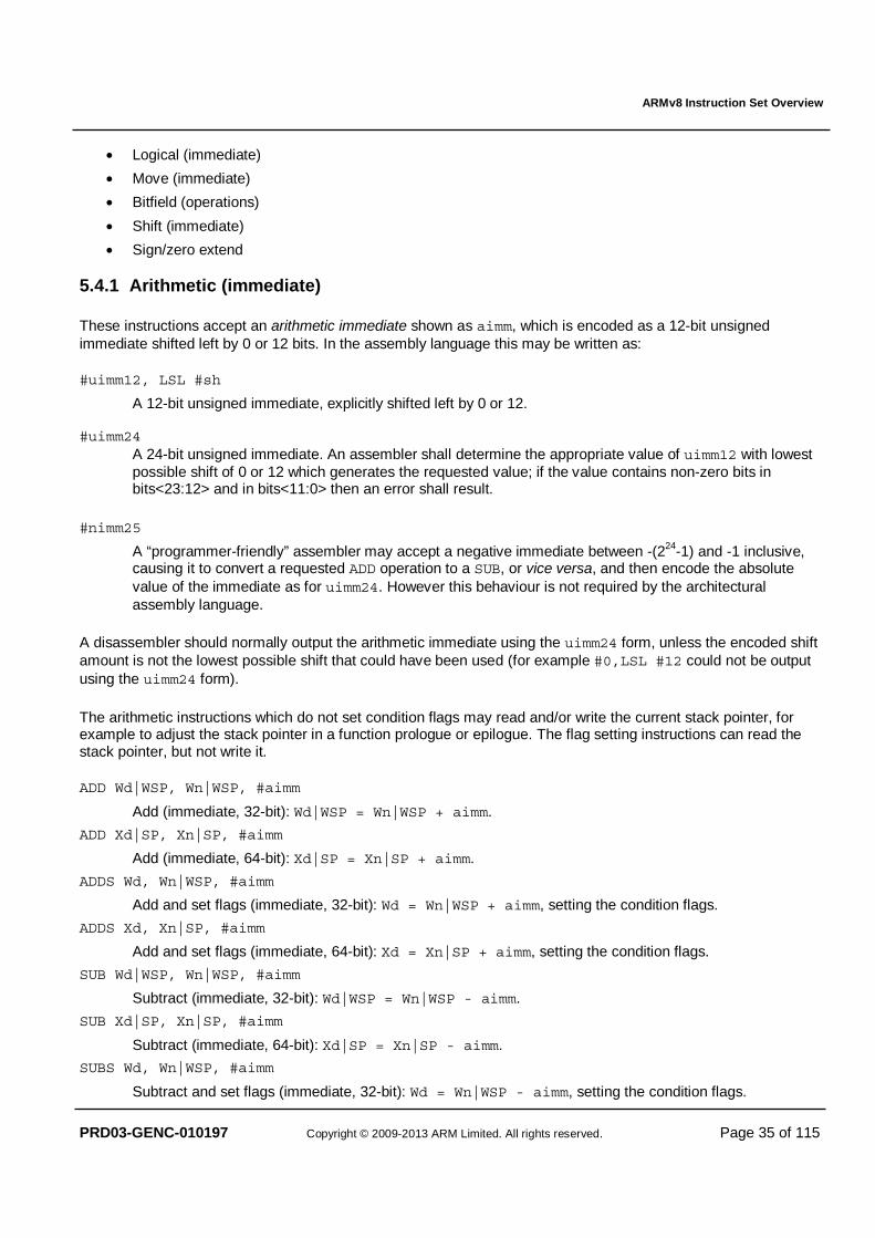
ARMv8 Instruction Set Overview
PRD03-GENC-010197 Copyright © 2009-2013 ARM Limited. All rights reserved. Page 35 of 115
• Logical (immediate)
• Move (immediate)
• Bitfield (operations)
• Shift (immediate)
• Sign/zero extend
5.4.1 Arithmetic (immediate)
These instructions accept an arithmetic immediate shown as aimm, which is encoded as a 12-bit unsigned immediate shifted left by 0 or 12 bits. In the assembly language this may be written as:
#uimm12, LSL #sh
A 12-bit unsigned immediate, explicitly shifted left by 0 or 12. #uimm24
A 24-bit unsigned immediate. An assembler shall determine the appropriate value of uimm12 with lowest possible shift of 0 or 12 which generates the requested value; if the value contains non-zero bits in bits<23:12> and in bits<11:0> then an error shall result.
#nimm25
A “programmer-friendly” assembler may accept a negative immediate between -(224-1) and -1 inclusive, causing it to convert a requested ADD operation to a SUB, or vice versa, and then encode the absolute value of the immediate as for uimm24. However this behaviour is not required by the architectural assembly language.
A disassembler should normally output the arithmetic immediate using the uimm24 form, unless the encoded shift amount is not the lowest possible shift that could have been used (for example #0,LSL #12 could not be output using the uimm24 form).
The arithmetic instructions which do not set condition flags may read and/or write the current stack pointer, for example to adjust the stack pointer in a function prologue or epilogue. The flag setting instructions can read the stack pointer, but not write it.
ADD Wd|WSP, Wn|WSP, #aimm
Add (immediate, 32-bit): Wd|WSP = Wn|WSP + aimm.
ADD Xd|SP, Xn|SP, #aimm
Add (immediate, 64-bit): Xd|SP = Xn|SP + aimm.
ADDS Wd, Wn|WSP, #aimm
Add and set flags (immediate, 32-bit): Wd = Wn|WSP + aimm, setting the condition flags.
ADDS Xd, Xn|SP, #aimm
Add and set flags (immediate, 64-bit): Xd = Xn|SP + aimm, setting the condition flags.
SUB Wd|WSP, Wn|WSP, #aimm
Subtract (immediate, 32-bit): Wd|WSP = Wn|WSP - aimm.
SUB Xd|SP, Xn|SP, #aimm
Subtract (immediate, 64-bit): Xd|SP = Xn|SP - aimm.
SUBS Wd, Wn|WSP, #aimm
Subtract and set flags (immediate, 32-bit): Wd = Wn|WSP - aimm, setting the condition flags.
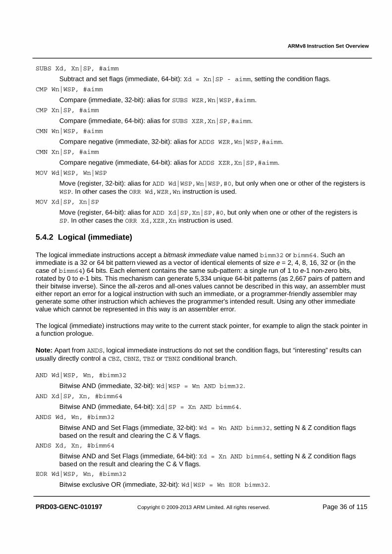
ARMv8 Instruction Set Overview
PRD03-GENC-010197 Copyright © 2009-2013 ARM Limited. All rights reserved. Page 36 of 115
SUBS Xd, Xn|SP, #aimm
Subtract and set flags (immediate, 64-bit): Xd = Xn|SP - aimm, setting the condition flags.
CMP Wn|WSP, #aimm
Compare (immediate, 32-bit): alias for SUBS WZR,Wn|WSP,#aimm.
CMP Xn|SP, #aimm
Compare (immediate, 64-bit): alias for SUBS XZR,Xn|SP,#aimm.
CMN Wn|WSP, #aimm
Compare negative (immediate, 32-bit): alias for ADDS WZR,Wn|WSP,#aimm.
CMN Xn|SP, #aimm
Compare negative (immediate, 64-bit): alias for ADDS XZR,Xn|SP,#aimm.
MOV Wd|WSP, Wn|WSP
Move (register, 32-bit): alias for ADD Wd|WSP,Wn|WSP,#0, but only when one or other of the registers is WSP. In other cases the ORR Wd,WZR,Wn instruction is used.
MOV Xd|SP, Xn|SP
Move (register, 64-bit): alias for ADD Xd|SP,Xn|SP,#0, but only when one or other of the registers is SP. In other cases the ORR Xd,XZR,Xn instruction is used.
5.4.2 Logical (immediate)
The logical immediate instructions accept a bitmask immediate value named bimm32 or bimm64. Such an immediate is a 32 or 64 bit pattern viewed as a vector of identical elements of size e = 2, 4, 8, 16, 32 or (in the case of bimm64) 64 bits. Each element contains the same sub-pattern: a single run of 1 to e-1 non-zero bits, rotated by 0 to e-1 bits. This mechanism can generate 5,334 unique 64-bit patterns (as 2,667 pairs of pattern and their bitwise inverse). Since the all-zeros and all-ones values cannot be described in this way, an assembler must either report an error for a logical instruction with such an immediate, or a programmer-friendly assembler may generate some other instruction which achieves the programmer's intended result. Using any other immediate value which cannot be represented in this way is an assembler error.
The logical (immediate) instructions may write to the current stack pointer, for example to align the stack pointer in a function prologue.
Note: Apart from ANDS, logical immediate instructions do not set the condition flags, but “interesting” results can usually directly control a CBZ, CBNZ, TBZ or TBNZ conditional branch.
AND Wd|WSP, Wn, #bimm32
Bitwise AND (immediate, 32-bit): Wd|WSP = Wn AND bimm32.
AND Xd|SP, Xn, #bimm64
Bitwise AND (immediate, 64-bit): Xd|SP = Xn AND bimm64.
ANDS Wd, Wn, #bimm32
Bitwise AND and Set Flags (immediate, 32-bit): Wd = Wn AND bimm32, setting N & Z condition flags based on the result and clearing the C & V flags.
ANDS Xd, Xn, #bimm64
Bitwise AND and Set Flags (immediate, 64-bit): Xd = Xn AND bimm64, setting N & Z condition flags based on the result and clearing the C & V flags.
EOR Wd|WSP, Wn, #bimm32
Bitwise exclusive OR (immediate, 32-bit): Wd|WSP = Wn EOR bimm32.
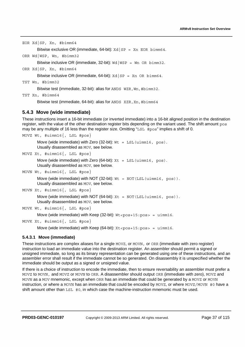
ARMv8 Instruction Set Overview
PRD03-GENC-010197 Copyright © 2009-2013 ARM Limited. All rights reserved. Page 37 of 115
EOR Xd|SP, Xn, #bimm64
Bitwise exclusive OR (immediate, 64-bit): Xd|SP = Xn EOR bimm64.
ORR Wd|WSP, Wn, #bimm32
Bitwise inclusive OR (immediate, 32-bit): Wd|WSP = Wn OR bimm32.
ORR Xd|SP, Xn, #bimm64
Bitwise inclusive OR (immediate, 64-bit): Xd|SP = Xn OR bimm64.
TST Wn, #bimm32
Bitwise test (immediate, 32-bit): alias for ANDS WZR,Wn,#bimm32.
TST Xn, #bimm64
Bitwise test (immediate, 64-bit): alias for ANDS XZR,Xn,#bimm64
5.4.3 Move (wide immediate) These instructions insert a 16-bit immediate (or inverted immediate) into a 16-bit aligned position in the destination register, with the value of the other destination register bits depending on the variant used. The shift amount pos may be any multiple of 16 less than the register size. Omitting “LSL #pos” implies a shift of 0.
MOVZ Wt, #uimm16{, LSL #pos}
Move (wide immediate) with Zero (32-bit): Wt = LSL(uimm16, pos). Usually disassembled as MOV, see below.
MOVZ Xt, #uimm16{, LSL #pos}
Move (wide immediate) with Zero (64-bit): Xt = LSL(uimm16, pos). Usually disassembled as MOV, see below.
MOVN Wt, #uimm16{, LSL #pos}
Move (wide immediate) with NOT (32-bit): Wt = NOT(LSL(uimm16, pos)). Usually disassembled as MOV, see below.
MOVN Xt, #uimm16{, LSL #pos}
Move (wide immediate) with NOT (64-bit): Xt = NOT(LSL(uimm16, pos)). Usually disassembled as MOV, see below.
MOVK Wt, #uimm16{, LSL #pos}
Move (wide immediate) with Keep (32-bit): Wt<pos+15:pos> = uimm16.
MOVK Xt, #uimm16{, LSL #pos}
Move (wide immediate) with Keep (64-bit): Xt<pos+15:pos> = uimm16.
5.4.3.1 Move (immediate) These instructions are complex aliases for a single MOVZ, or MOVN, or ORR (immediate with zero register) instruction to load an immediate value into the destination register. An assembler should permit a signed or unsigned immediate, so long as its binary representation can be generated using one of these instructions, and an assembler error shall result if the immediate cannot be so generated. On disassembly it is unspecified whether the immediate should be output as a signed or unsigned value.
If there is a choice of instruction to encode the immediate, then to ensure reversability an assembler must prefer a MOVZ to MOVN, and MOVZ or MOVN to ORR. A disassembler should output ORR (immediate with zero), MOVZ and MOVN as a MOV mnemonic, except when ORR has an immediate that could be generated by a MOVZ or MOVN instruction, or where a MOVN has an immediate that could be encoded by MOVZ, or where MOVZ/MOVN #0 have a shift amount other than LSL #0, in which case the machine-instruction mnemonic must be used.
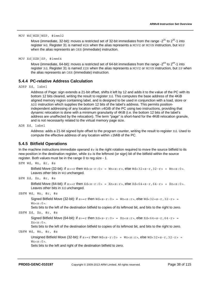
ARMv8 Instruction Set Overview
PRD03-GENC-010197 Copyright © 2009-2013 ARM Limited. All rights reserved. Page 38 of 115
MOV Wd|WZR|WSP, #imm32
Move (immediate, 32-bit): moves a restricted set of 32-bit immediates from the range -231 to 232-1 into register Wd. Register 31 is named WZR when the alias represents a MOVZ or MOVN instruction, but WSP when the alias represents an ORR (immediate) instruction.
MOV Xd|XZR|SP, #imm64
Move (immediate, 64-bit): moves a restricted set of 64-bit immediates from the range -263 to 264-1 into register Xd. Register 31 is named XZR when the alias represents a MOVZ or MOVN instruction, but SP when the alias represents an ORR (immediate) instruction.
5.4.4 PC-relative Address Calculation ADRP Xd, label
Address of Page: sign extends a 21-bit offset, shifts it left by 12 and adds it to the value of the PC with its bottom 12 bits cleared, writing the result to register Xd. This computes the base address of the 4KiB aligned memory region containing label, and is designed to be used in conjunction with a load, store or ADD instruction which supplies the bottom 12 bits of the label’s address. This permits position-independent addressing of any location within ±4GiB of the PC using two instructions, providing that dynamic relocation is done with a minimum granularity of 4KiB (i.e. the bottom 12 bits of the label’s address are unaffected by the relocation). The term “page” is short-hand for the 4KiB relocation granule, and is not necessarily related to the virtual memory page size.
ADR Xd, label
Address: adds a 21-bit signed byte offset to the program counter, writing the result to register Xd. Used to compute the effective address of any location within ±1MiB of the PC.
5.4.5 Bitfield Operations In the machine instructions immediate operand #r is the right rotation required to move the source bitfield to its new position in the destination register, while #s is the leftmost (or sign) bit of the bitfield within the source register. Both values must be in the range 0 to reg.size - 1. BFM Wd, Wn, #r, #s
Bitfield Move (32-bit): if s>=r then Wd<s-r:0> = Wn<s:r>, else Wd<32+s-r,32-r> = Wn<s:0>. Leaves other bits in Wd unchanged.
BFM Xd, Xn, #r, #s
Bitfield Move (64-bit): if s>=r then Xd<s-r:0> = Xn<s:r>, else Xd<64+s-r,64-r> = Xn<s:0>. Leaves other bits in Xd unchanged.
SBFM Wd, Wn, #r, #s
Signed Bitfield Move (32-bit): if s>=r then Wd<s-r:0> = Wn<s:r>, else Wd<32+s-r,32-r> = Wn<s:0>. Sets bits to the left of the destination bitfield to copies of its leftmost bit, and bits to the right to zero.
SBFM Xd, Xn, #r, #s
Signed Bitfield Move (64-bit): if s>=r then Xd<s-r:0> = Xn<s:r>, else Xd<64+s-r,64-r> = Xn<s:0>. Sets bits to the left of the destination bitfield to copies of its leftmost bit, and bits to the right to zero.
UBFM Wd, Wn, #r, #s
Unsigned Bitfield Move (32-bit): if s>=r then Wd<s-r:0> = Wn<s:r>, else Wd<32+s-r,32-r> = Wn<s:0>. Sets bits to the left and right of the destination bitfield to zero.
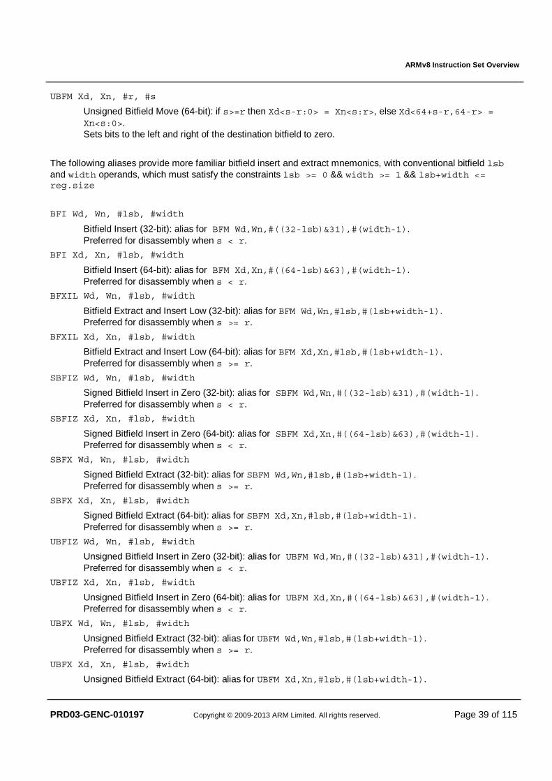
ARMv8 Instruction Set Overview
PRD03-GENC-010197 Copyright © 2009-2013 ARM Limited. All rights reserved. Page 39 of 115
UBFM Xd, Xn, #r, #s
Unsigned Bitfield Move (64-bit): if s>=r then Xd<s-r:0> = Xn<s:r>, else Xd<64+s-r,64-r> = Xn<s:0>. Sets bits to the left and right of the destination bitfield to zero.
The following aliases provide more familiar bitfield insert and extract mnemonics, with conventional bitfield lsb and width operands, which must satisfy the constraints lsb >= 0 && width >= 1 && lsb+width <= reg.size
BFI Wd, Wn, #lsb, #width
Bitfield Insert (32-bit): alias for BFM Wd,Wn,#((32-lsb)&31),#(width-1). Preferred for disassembly when s < r.
BFI Xd, Xn, #lsb, #width
Bitfield Insert (64-bit): alias for BFM Xd,Xn,#((64-lsb)&63),#(width-1). Preferred for disassembly when s < r.
BFXIL Wd, Wn, #lsb, #width
Bitfield Extract and Insert Low (32-bit): alias for BFM Wd,Wn,#lsb,#(lsb+width-1). Preferred for disassembly when s >= r.
BFXIL Xd, Xn, #lsb, #width
Bitfield Extract and Insert Low (64-bit): alias for BFM Xd,Xn,#lsb,#(lsb+width-1). Preferred for disassembly when s >= r.
SBFIZ Wd, Wn, #lsb, #width
Signed Bitfield Insert in Zero (32-bit): alias for SBFM Wd,Wn,#((32-lsb)&31),#(width-1). Preferred for disassembly when s < r.
SBFIZ Xd, Xn, #lsb, #width
Signed Bitfield Insert in Zero (64-bit): alias for SBFM Xd,Xn,#((64-lsb)&63),#(width-1). Preferred for disassembly when s < r.
SBFX Wd, Wn, #lsb, #width
Signed Bitfield Extract (32-bit): alias for SBFM Wd,Wn,#lsb,#(lsb+width-1). Preferred for disassembly when s >= r.
SBFX Xd, Xn, #lsb, #width
Signed Bitfield Extract (64-bit): alias for SBFM Xd,Xn,#lsb,#(lsb+width-1). Preferred for disassembly when s >= r.
UBFIZ Wd, Wn, #lsb, #width
Unsigned Bitfield Insert in Zero (32-bit): alias for UBFM Wd,Wn,#((32-lsb)&31),#(width-1). Preferred for disassembly when s < r.
UBFIZ Xd, Xn, #lsb, #width
Unsigned Bitfield Insert in Zero (64-bit): alias for UBFM Xd,Xn,#((64-lsb)&63),#(width-1). Preferred for disassembly when s < r.
UBFX Wd, Wn, #lsb, #width
Unsigned Bitfield Extract (32-bit): alias for UBFM Wd,Wn,#lsb,#(lsb+width-1). Preferred for disassembly when s >= r.
UBFX Xd, Xn, #lsb, #width
Unsigned Bitfield Extract (64-bit): alias for UBFM Xd,Xn,#lsb,#(lsb+width-1).
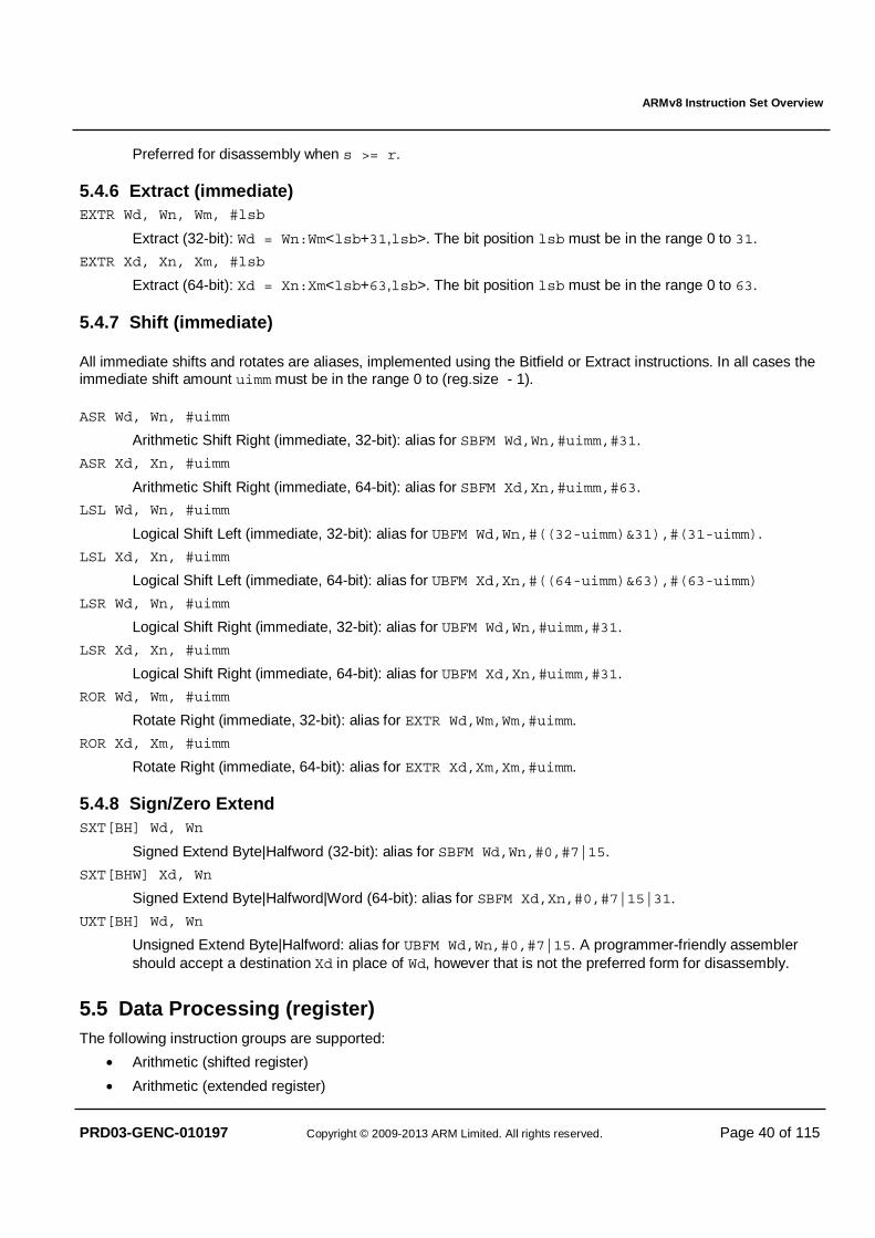
ARMv8 Instruction Set Overview
PRD03-GENC-010197 Copyright © 2009-2013 ARM Limited. All rights reserved. Page 40 of 115
Preferred for disassembly when s >= r.
5.4.6 Extract (immediate) EXTR Wd, Wn, Wm, #lsb
Extract (32-bit): Wd = Wn:Wm<lsb+31,lsb>. The bit position lsb must be in the range 0 to 31.
EXTR Xd, Xn, Xm, #lsb
Extract (64-bit): Xd = Xn:Xm<lsb+63,lsb>. The bit position lsb must be in the range 0 to 63.
5.4.7 Shift (immediate)
All immediate shifts and rotates are aliases, implemented using the Bitfield or Extract instructions. In all cases the immediate shift amount uimm must be in the range 0 to (reg.size - 1).
ASR Wd, Wn, #uimm
Arithmetic Shift Right (immediate, 32-bit): alias for SBFM Wd,Wn,#uimm,#31.
ASR Xd, Xn, #uimm
Arithmetic Shift Right (immediate, 64-bit): alias for SBFM Xd,Xn,#uimm,#63.
LSL Wd, Wn, #uimm
Logical Shift Left (immediate, 32-bit): alias for UBFM Wd,Wn,#((32-uimm)&31),#(31-uimm).
LSL Xd, Xn, #uimm
Logical Shift Left (immediate, 64-bit): alias for UBFM Xd,Xn,#((64-uimm)&63),#(63-uimm)
LSR Wd, Wn, #uimm
Logical Shift Right (immediate, 32-bit): alias for UBFM Wd,Wn,#uimm,#31.
LSR Xd, Xn, #uimm
Logical Shift Right (immediate, 64-bit): alias for UBFM Xd,Xn,#uimm,#31.
ROR Wd, Wm, #uimm
Rotate Right (immediate, 32-bit): alias for EXTR Wd,Wm,Wm,#uimm.
ROR Xd, Xm, #uimm
Rotate Right (immediate, 64-bit): alias for EXTR Xd,Xm,Xm,#uimm.
5.4.8 Sign/Zero Extend SXT[BH] Wd, Wn
Signed Extend Byte|Halfword (32-bit): alias for SBFM Wd,Wn,#0,#7|15.
SXT[BHW] Xd, Wn
Signed Extend Byte|Halfword|Word (64-bit): alias for SBFM Xd,Xn,#0,#7|15|31.
UXT[BH] Wd, Wn
Unsigned Extend Byte|Halfword: alias for UBFM Wd,Wn,#0,#7|15. A programmer-friendly assembler should accept a destination Xd in place of Wd, however that is not the preferred form for disassembly.
5.5 Data Processing (register) The following instruction groups are supported:
• Arithmetic (shifted register)
• Arithmetic (extended register)
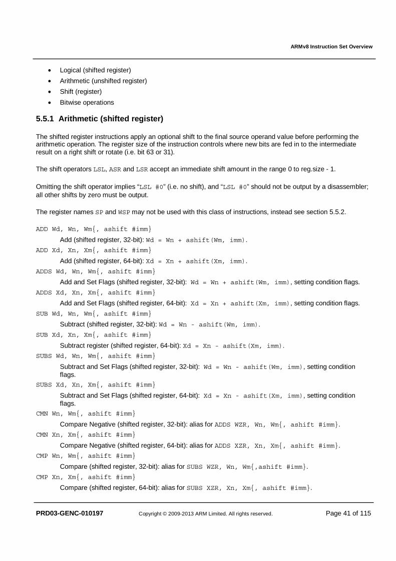
ARMv8 Instruction Set Overview
PRD03-GENC-010197 Copyright © 2009-2013 ARM Limited. All rights reserved. Page 41 of 115
• Logical (shifted register)
• Arithmetic (unshifted register)
• Shift (register)
• Bitwise operations
5.5.1 Arithmetic (shifted register)
The shifted register instructions apply an optional shift to the final source operand value before performing the arithmetic operation. The register size of the instruction controls where new bits are fed in to the intermediate result on a right shift or rotate (i.e. bit 63 or 31).
The shift operators LSL, ASR and LSR accept an immediate shift amount in the range 0 to reg.size - 1.
Omitting the shift operator implies “LSL #0” (i.e. no shift), and “LSL #0” should not be output by a disassembler; all other shifts by zero must be output.
The register names SP and WSP may not be used with this class of instructions, instead see section 5.5.2.
ADD Wd, Wn, Wm{, ashift #imm}
Add (shifted register, 32-bit): Wd = Wn + ashift(Wm, imm).
ADD Xd, Xn, Xm{, ashift #imm}
Add (shifted register, 64-bit): Xd = Xn + ashift(Xm, imm).
ADDS Wd, Wn, Wm{, ashift #imm}
Add and Set Flags (shifted register, 32-bit): Wd = Wn + ashift(Wm, imm), setting condition flags.
ADDS Xd, Xn, Xm{, ashift #imm}
Add and Set Flags (shifted register, 64-bit): Xd = Xn + ashift(Xm, imm), setting condition flags.
SUB Wd, Wn, Wm{, ashift #imm}
Subtract (shifted register, 32-bit): Wd = Wn - ashift(Wm, imm).
SUB Xd, Xn, Xm{, ashift #imm}
Subtract register (shifted register, 64-bit): Xd = Xn - ashift(Xm, imm).
SUBS Wd, Wn, Wm{, ashift #imm}
Subtract and Set Flags (shifted register, 32-bit): Wd = Wn - ashift(Wm, imm), setting condition flags.
SUBS Xd, Xn, Xm{, ashift #imm}
Subtract and Set Flags (shifted register, 64-bit): Xd = Xn - ashift(Xm, imm), setting condition flags.
CMN Wn, Wm{, ashift #imm}
Compare Negative (shifted register, 32-bit): alias for ADDS WZR, Wn, Wm{, ashift #imm}.
CMN Xn, Xm{, ashift #imm}
Compare Negative (shifted register, 64-bit): alias for ADDS XZR, Xn, Xm{, ashift #imm}.
CMP Wn, Wm{, ashift #imm}
Compare (shifted register, 32-bit): alias for SUBS WZR, Wn, Wm{,ashift #imm}.
CMP Xn, Xm{, ashift #imm}
Compare (shifted register, 64-bit): alias for SUBS XZR, Xn, Xm{, ashift #imm}.
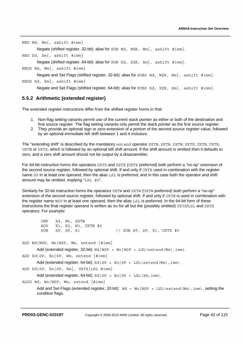
ARMv8 Instruction Set Overview
PRD03-GENC-010197 Copyright © 2009-2013 ARM Limited. All rights reserved. Page 42 of 115
NEG Wd, Wm{, ashift #imm}
Negate (shifted register, 32-bit): alias for SUB Wd, WZR, Wm{, ashift #imm}.
NEG Xd, Xm{, ashift #imm}
Negate (shifted register, 64-bit): alias for SUB Xd, XZR, Xm{, ashift #imm}.
NEGS Wd, Wm{, ashift #imm}
Negate and Set Flags (shifted register, 32-bit): alias for SUBS Wd, WZR, Wm{, ashift #imm}.
NEGS Xd, Xm{, ashift #imm}
Negate and Set Flags (shifted register, 64-bit): alias for SUBS Xd, XZR, Xm{, ashift #imm}.
5.5.2 Arithmetic (extended register)
The extended register instructions differ from the shifted register forms in that:
1. Non-flag setting variants permit use of the current stack pointer as either or both of the destination and first source register. The flag setting variants only permit the stack pointer as the first source register.
2. They provide an optional sign or zero-extension of a portion of the second source register value, followed by an optional immediate left shift between 1 and 4 inclusive.
The "extending shift" is described by the mandatory extend operator SXTB, SXTH, SXTW, SXTX, UXTB, UXTH, UXTW or UXTX, which is followed by an optional left shift amount. If the shift amount is omitted then it defaults to zero, and a zero shift amount should not be output by a disassembler.
For 64-bit instruction forms the operators UXTX and SXTX (UXTX preferred) both perform a “no-op” extension of the second source register, followed by optional shift. If and only if UXTX used in combination with the register name SP in at least one operand, then the alias LSL is preferred, and in this case both the operator and shift amount may be omitted, implying “LSL #0”.
Similarly for 32-bit instruction forms the operators UXTW and SXTW (UXTW preferred) both perform a “no-op” extension of the second source register, followed by optional shift. If and only if UXTW is used in combination with the register name WSP in at least one operand, then the alias LSL is preferred. In the 64-bit form of these instructions the final register operand is written as Wm for all but the (possibly omitted) UXTX/LSL and SXTX operators. For example:
CMP X4, W5, SXTW ADD X1, X2, W3, UXTB #2 SUB SP, SP, X1 // SUB SP, SP, X1, UXTX #0
ADD Wd|WSP, Wn|WSP, Wm, extend {#imm}
Add (extended register, 32-bit): Wd|WSP = Wn|WSP + LSL(extend(Wm),imm).
ADD Xd|SP, Xn|SP, Wm, extend {#imm}
Add (extended register, 64-bit): Xd|SP = Xn|SP + LSL(extend(Wm),imm).
ADD Xd|SP, Xn|SP, Xm{, UXTX|LSL #imm}
Add (extended register, 64-bit): Xd|SP = Xn|SP + LSL(Xm,imm).
ADDS Wd, Wn|WSP, Wm, extend {#imm}
Add and Set Flags (extended register, 32-bit): Wd = Wn|WSP + LSL(extend(Wm),imm), setting the condition flags.

ARMv8 Instruction Set Overview
PRD03-GENC-010197 Copyright © 2009-2013 ARM Limited. All rights reserved. Page 43 of 115
ADDS Xd, Xn|SP, Wm, extend {#imm}
Add and Set Flags (extended register, 64-bit): Xd = Xn|SP + LSL(extend(Wm),imm), setting the condition flags.
ADDS Xd, Xn|SP, Xm{, UXTX|LSL #imm}
Add and Set Flags (extended register, 64-bit): Xd = Xn|SP + LSL(Xm,imm), setting the condition flags.
SUB Wd|WSP, Wn|WSP, Wm, extend {#imm}
Subtract (extended register, 32-bit): Wd|WSP = Wn|WSP - LSL(extend(Wm),imm).
SUB Xd|SP, Xn|SP, Wm, extend {#imm}
Subtract (extended register, 64-bit): Xd|SP = Xn|SP - LSL(extend(Wm),imm).
SUB Xd|SP, Xn|SP, Xm{, UXTX|LSL #imm}
Subtract (extended register, 64-bit): Xd|SP = Xn|SP - LSL(Xm,imm).
SUBS Wd, Wn|WSP, Wm, extend {#imm}
Subtract and Set Flags (extended register, 32-bit): Wd = Wn|WSP - LSL(extend(Wm),imm), setting the condition flags.
SUBS Xd, Xn|SP, Wm, extend {#imm}
Subtract and Set Flags (extended register, 64-bit): Xd = Xn|SP - LSL(extend(Wm),imm), setting the condition flags.
SUBS Xd, Xn|SP, Xm{, UXTX|LSL #imm}
Subtract and Set Flags (extended register, 64-bit): Xd = Xn|SP - LSL(Xm,imm), setting the condition flags.
CMN Wn|WSP, Wm, extend {#imm}
Compare Negative (extended register, 32-bit): alias for ADDS WZR,Wn,Wm,extend {#imm}.
CMN Xn|SP, Wm, extend {#imm}
Compare Negative (extended register, 64-bit): alias for ADDS XZR,Xn,Wm,extend {#imm}.
CMN Xn|SP, Xm{, UXTX|LSL #imm}
Compare Negative (extended register, 64-bit): alias for ADDS XZR,Xn,Xm{,UXTX|LSL #imm}.
CMP Wn|WSP, Wm, extend {#imm}
Compare (extended register, 32-bit): alias for SUBS WZR,Wn,Wm,extend {#imm}.
CMP Xn|SP, Wm, extend {#imm}
Compare (extended register, 64-bit): alias for SUBS XZR,Xn,Wm,extend {#imm}.
CMP Xn|SP, Xm{, UXTX|LSL #imm}
Compare (extended register, 64-bit): alias for SUBS XZR,Xn,Xm{,UXTX|LSL #imm}.
5.5.3 Logical (shifted register)
The logical (shifted register) instructions apply an optional shift operator to their final source operand before performing the main operation. The register size of the instruction controls where new bits are fed in to the intermediate result on a right shift or rotate (i.e. bit 63 or 31).
The shift operators LSL, ASR, LSR and ROR accept an immediate shift amount in the range 0 to reg.size - 1.
Omitting the shift operator implies “LSL #0” (i.e. no shift), and an “LSL #0” should not be output by a disassembler – however all other shifts by zero must be output.
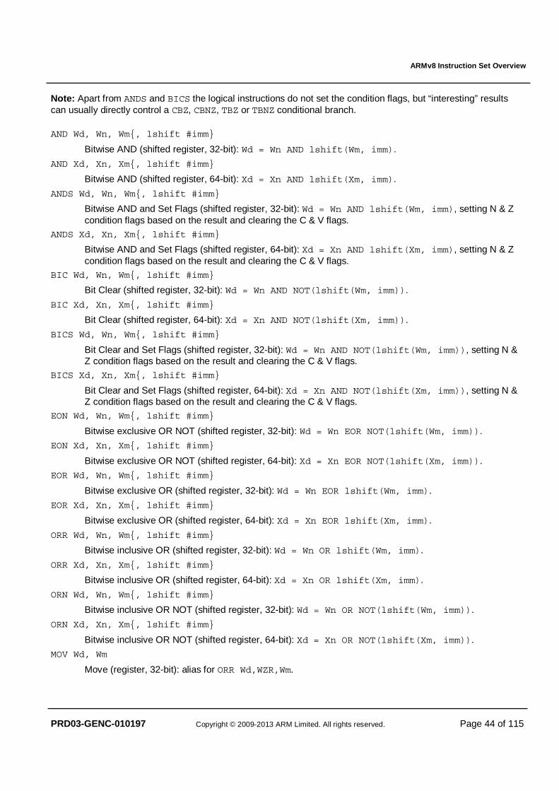
ARMv8 Instruction Set Overview
PRD03-GENC-010197 Copyright © 2009-2013 ARM Limited. All rights reserved. Page 44 of 115
Note: Apart from ANDS and BICS the logical instructions do not set the condition flags, but “interesting” results can usually directly control a CBZ, CBNZ, TBZ or TBNZ conditional branch.
AND Wd, Wn, Wm{, lshift #imm}
Bitwise AND (shifted register, 32-bit): Wd = Wn AND lshift(Wm, imm).
AND Xd, Xn, Xm{, lshift #imm}
Bitwise AND (shifted register, 64-bit): Xd = Xn AND lshift(Xm, imm).
ANDS Wd, Wn, Wm{, lshift #imm}
Bitwise AND and Set Flags (shifted register, 32-bit): Wd = Wn AND lshift(Wm, imm), setting N & Z condition flags based on the result and clearing the C & V flags.
ANDS Xd, Xn, Xm{, lshift #imm}
Bitwise AND and Set Flags (shifted register, 64-bit): Xd = Xn AND lshift(Xm, imm), setting N & Z condition flags based on the result and clearing the C & V flags.
BIC Wd, Wn, Wm{, lshift #imm}
Bit Clear (shifted register, 32-bit): Wd = Wn AND NOT(lshift(Wm, imm)).
BIC Xd, Xn, Xm{, lshift #imm}
Bit Clear (shifted register, 64-bit): Xd = Xn AND NOT(lshift(Xm, imm)).
BICS Wd, Wn, Wm{, lshift #imm}
Bit Clear and Set Flags (shifted register, 32-bit): Wd = Wn AND NOT(lshift(Wm, imm)), setting N & Z condition flags based on the result and clearing the C & V flags.
BICS Xd, Xn, Xm{, lshift #imm}
Bit Clear and Set Flags (shifted register, 64-bit): Xd = Xn AND NOT(lshift(Xm, imm)), setting N & Z condition flags based on the result and clearing the C & V flags.
EON Wd, Wn, Wm{, lshift #imm}
Bitwise exclusive OR NOT (shifted register, 32-bit): Wd = Wn EOR NOT(lshift(Wm, imm)).
EON Xd, Xn, Xm{, lshift #imm}
Bitwise exclusive OR NOT (shifted register, 64-bit): Xd = Xn EOR NOT(lshift(Xm, imm)).
EOR Wd, Wn, Wm{, lshift #imm}
Bitwise exclusive OR (shifted register, 32-bit): Wd = Wn EOR lshift(Wm, imm).
EOR Xd, Xn, Xm{, lshift #imm}
Bitwise exclusive OR (shifted register, 64-bit): Xd = Xn EOR lshift(Xm, imm).
ORR Wd, Wn, Wm{, lshift #imm}
Bitwise inclusive OR (shifted register, 32-bit): Wd = Wn OR lshift(Wm, imm).
ORR Xd, Xn, Xm{, lshift #imm}
Bitwise inclusive OR (shifted register, 64-bit): Xd = Xn OR lshift(Xm, imm).
ORN Wd, Wn, Wm{, lshift #imm}
Bitwise inclusive OR NOT (shifted register, 32-bit): Wd = Wn OR NOT(lshift(Wm, imm)).
ORN Xd, Xn, Xm{, lshift #imm}
Bitwise inclusive OR NOT (shifted register, 64-bit): Xd = Xn OR NOT(lshift(Xm, imm)).
MOV Wd, Wm
Move (register, 32-bit): alias for ORR Wd,WZR,Wm.

ARMv8 Instruction Set Overview
PRD03-GENC-010197 Copyright © 2009-2013 ARM Limited. All rights reserved. Page 45 of 115
MOV Xd, Xm
Move (register, 64-bit): alias for ORR Xd,XZR,Xm.
MVN Wd, Wm{, lshift #imm}
Move NOT (shifted register, 32-bit): alias for ORN Wd,WZR,Wm{,lshift #imm}.
MVN Xd, Xm{, lshift #imm}
Move NOT (shifted register, 64-bit): alias for ORN Xd,XZR,Xm{,lshift #imm}.
TST Wn, Wm{, lshift #imm}
Bitwise Test (shifted register, 32-bit): alias for ANDS WZR,Wn,Wm{,lshift #imm}.
TST Xn, Xm{, lshift #imm}
Bitwise Test (shifted register, 64-bit): alias for ANDS XZR,Xn,Xm{,lshift #imm}.
5.5.4 Variable Shift The variable shift amount in Wm or Xm is positive, and modulo the register size. For example an 64-bit shift with Xm containing the value 65 will result in a shift by (65 MOD 64) = 1 bit. The machine instructions are as follows:
ASRV Wd, Wn, Wm
Arithmetic Shift Right Variable (32-bit): Wd = ASR(Wn, Wm & 0x1f).
ASRV Xd, Xn, Xm
Arithmetic Shift Right Variable (64-bit): Xd = ASR(Xn, Xm & 0x3f).
LSLV Wd, Wn, Wm
Logical Shift Left Variable (32-bit): Wd = LSL(Wn, Wm & 0x1f).
LSLV Xd, Xn, Xm
Logical Shift Left Variable (64-bit): Xd = LSL(Xn, Xm & 0x3f).
LSRV Wd, Wn, Wm
Logical Shift Right Variable (32-bit): Wd = LSR(Wn, Wm & 0x1f).
LSRV Xd, Xn, Xm
Logical Shift Right Variable (64-bit): Xd = LSR(Xn, Xm & 0x3f).
RORV Wd, Wn, Wm
Rotate Right Variable (32-bit): Wd = ROR(Wn, Wm & 0x1f).
RORV Xd, Xn, Xm
Rotate Right Variable (64-bit): Xd = ROR(Xn, Xm & 0x3f). However the “Variable Shift” machine instructions have a preferred set of “Shift (register)” aliases which match the Shift (immediate) aliases described elsewhere:
ASR Wd, Wn, Wm
Arithmetic Shift Right (register, 32-bit): preferred alias for ASRV Wd, Wn, Wm.
ASR Xd, Xn, Xm
Arithmetic Shift Right (register, 64-bit): preferred alias for ASRV Xd, Xn, Xm.
LSL Wd, Wn, Wm
Logical Shift Left (register, 32-bit): preferred alias for LSLV Wd, Wn, Wm.
LSL Xd, Xn, Xm
Logical Shift Left (register, 64-bit): preferred alias for LSLV Xd, Xn, Xm.
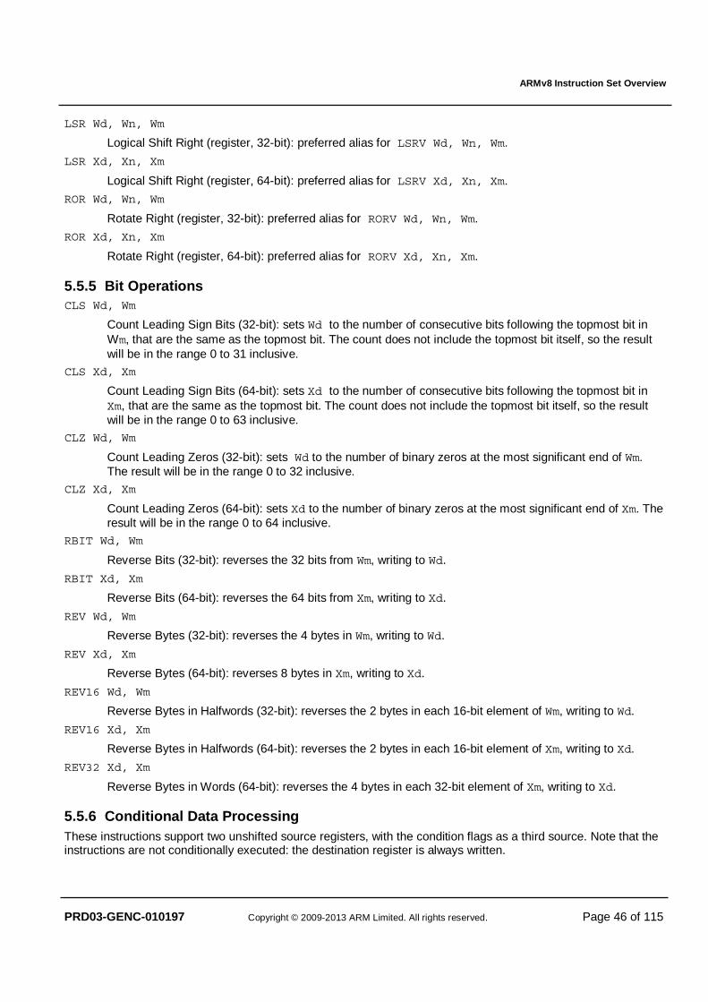
ARMv8 Instruction Set Overview
PRD03-GENC-010197 Copyright © 2009-2013 ARM Limited. All rights reserved. Page 46 of 115
LSR Wd, Wn, Wm
Logical Shift Right (register, 32-bit): preferred alias for LSRV Wd, Wn, Wm.
LSR Xd, Xn, Xm
Logical Shift Right (register, 64-bit): preferred alias for LSRV Xd, Xn, Xm.
ROR Wd, Wn, Wm
Rotate Right (register, 32-bit): preferred alias for RORV Wd, Wn, Wm.
ROR Xd, Xn, Xm
Rotate Right (register, 64-bit): preferred alias for RORV Xd, Xn, Xm.
5.5.5 Bit Operations CLS Wd, Wm
Count Leading Sign Bits (32-bit): sets Wd to the number of consecutive bits following the topmost bit in Wm, that are the same as the topmost bit. The count does not include the topmost bit itself, so the result will be in the range 0 to 31 inclusive.
CLS Xd, Xm
Count Leading Sign Bits (64-bit): sets Xd to the number of consecutive bits following the topmost bit in Xm, that are the same as the topmost bit. The count does not include the topmost bit itself, so the result will be in the range 0 to 63 inclusive.
CLZ Wd, Wm
Count Leading Zeros (32-bit): sets Wd to the number of binary zeros at the most significant end of Wm. The result will be in the range 0 to 32 inclusive.
CLZ Xd, Xm
Count Leading Zeros (64-bit): sets Xd to the number of binary zeros at the most significant end of Xm. The result will be in the range 0 to 64 inclusive.
RBIT Wd, Wm
Reverse Bits (32-bit): reverses the 32 bits from Wm, writing to Wd.
RBIT Xd, Xm
Reverse Bits (64-bit): reverses the 64 bits from Xm, writing to Xd.
REV Wd, Wm
Reverse Bytes (32-bit): reverses the 4 bytes in Wm, writing to Wd.
REV Xd, Xm
Reverse Bytes (64-bit): reverses 8 bytes in Xm, writing to Xd.
REV16 Wd, Wm
Reverse Bytes in Halfwords (32-bit): reverses the 2 bytes in each 16-bit element of Wm, writing to Wd.
REV16 Xd, Xm
Reverse Bytes in Halfwords (64-bit): reverses the 2 bytes in each 16-bit element of Xm, writing to Xd.
REV32 Xd, Xm
Reverse Bytes in Words (64-bit): reverses the 4 bytes in each 32-bit element of Xm, writing to Xd.
5.5.6 Conditional Data Processing These instructions support two unshifted source registers, with the condition flags as a third source. Note that the instructions are not conditionally executed: the destination register is always written.
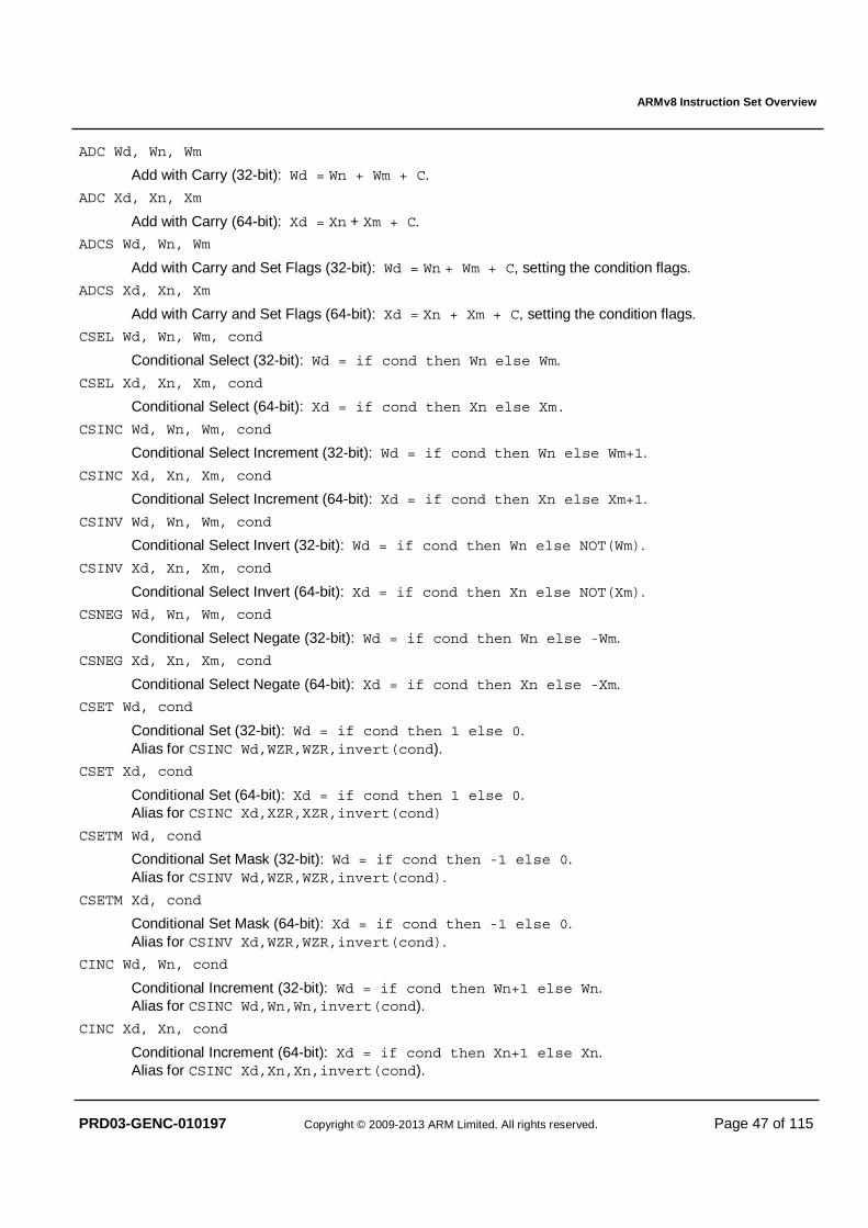
ARMv8 Instruction Set Overview
PRD03-GENC-010197 Copyright © 2009-2013 ARM Limited. All rights reserved. Page 47 of 115
ADC Wd, Wn, Wm
Add with Carry (32-bit): Wd = Wn + Wm + C.
ADC Xd, Xn, Xm
Add with Carry (64-bit): Xd = Xn + Xm + C.
ADCS Wd, Wn, Wm
Add with Carry and Set Flags (32-bit): Wd = Wn + Wm + C, setting the condition flags.
ADCS Xd, Xn, Xm
Add with Carry and Set Flags (64-bit): Xd = Xn + Xm + C, setting the condition flags.
CSEL Wd, Wn, Wm, cond
Conditional Select (32-bit): Wd = if cond then Wn else Wm.
CSEL Xd, Xn, Xm, cond
Conditional Select (64-bit): Xd = if cond then Xn else Xm.
CSINC Wd, Wn, Wm, cond
Conditional Select Increment (32-bit): Wd = if cond then Wn else Wm+1.
CSINC Xd, Xn, Xm, cond
Conditional Select Increment (64-bit): Xd = if cond then Xn else Xm+1.
CSINV Wd, Wn, Wm, cond
Conditional Select Invert (32-bit): Wd = if cond then Wn else NOT(Wm).
CSINV Xd, Xn, Xm, cond
Conditional Select Invert (64-bit): Xd = if cond then Xn else NOT(Xm).
CSNEG Wd, Wn, Wm, cond
Conditional Select Negate (32-bit): Wd = if cond then Wn else -Wm.
CSNEG Xd, Xn, Xm, cond
Conditional Select Negate (64-bit): Xd = if cond then Xn else -Xm.
CSET Wd, cond
Conditional Set (32-bit): Wd = if cond then 1 else 0. Alias for CSINC Wd,WZR,WZR,invert(cond).
CSET Xd, cond
Conditional Set (64-bit): Xd = if cond then 1 else 0. Alias for CSINC Xd,XZR,XZR,invert(cond)
CSETM Wd, cond
Conditional Set Mask (32-bit): Wd = if cond then -1 else 0. Alias for CSINV Wd,WZR,WZR,invert(cond).
CSETM Xd, cond
Conditional Set Mask (64-bit): Xd = if cond then -1 else 0. Alias for CSINV Xd,WZR,WZR,invert(cond).
CINC Wd, Wn, cond
Conditional Increment (32-bit): Wd = if cond then Wn+1 else Wn. Alias for CSINC Wd,Wn,Wn,invert(cond).
CINC Xd, Xn, cond
Conditional Increment (64-bit): Xd = if cond then Xn+1 else Xn. Alias for CSINC Xd,Xn,Xn,invert(cond).
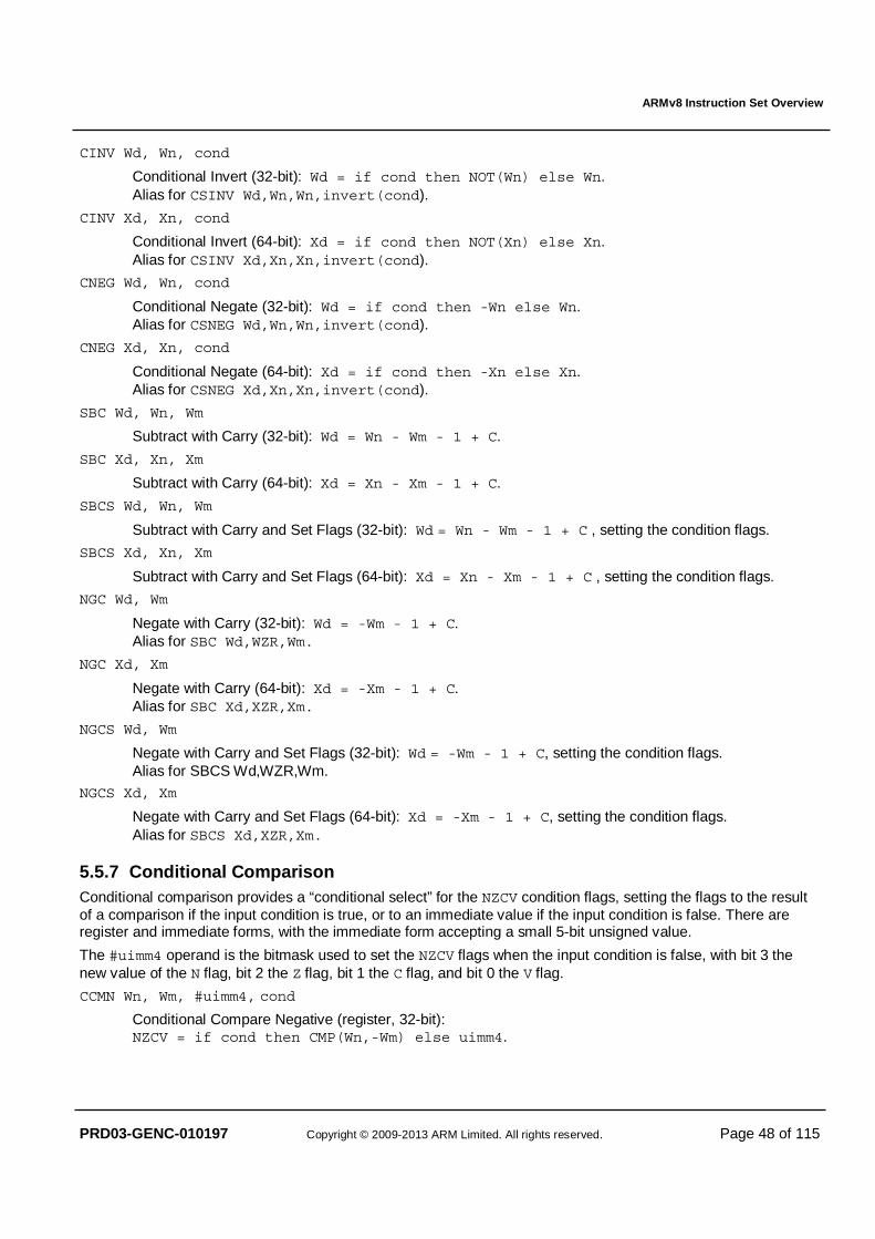
ARMv8 Instruction Set Overview
PRD03-GENC-010197 Copyright © 2009-2013 ARM Limited. All rights reserved. Page 48 of 115
CINV Wd, Wn, cond
Conditional Invert (32-bit): Wd = if cond then NOT(Wn) else Wn. Alias for CSINV Wd,Wn,Wn,invert(cond).
CINV Xd, Xn, cond
Conditional Invert (64-bit): Xd = if cond then NOT(Xn) else Xn. Alias for CSINV Xd,Xn,Xn,invert(cond).
CNEG Wd, Wn, cond
Conditional Negate (32-bit): Wd = if cond then -Wn else Wn. Alias for CSNEG Wd,Wn,Wn,invert(cond).
CNEG Xd, Xn, cond
Conditional Negate (64-bit): Xd = if cond then -Xn else Xn. Alias for CSNEG Xd,Xn,Xn,invert(cond).
SBC Wd, Wn, Wm
Subtract with Carry (32-bit): Wd = Wn - Wm - 1 + C.
SBC Xd, Xn, Xm
Subtract with Carry (64-bit): Xd = Xn - Xm - 1 + C.
SBCS Wd, Wn, Wm
Subtract with Carry and Set Flags (32-bit): Wd = Wn - Wm - 1 + C , setting the condition flags.
SBCS Xd, Xn, Xm
Subtract with Carry and Set Flags (64-bit): Xd = Xn - Xm - 1 + C , setting the condition flags.
NGC Wd, Wm
Negate with Carry (32-bit): Wd = -Wm - 1 + C. Alias for SBC Wd,WZR,Wm.
NGC Xd, Xm
Negate with Carry (64-bit): Xd = -Xm - 1 + C. Alias for SBC Xd,XZR,Xm.
NGCS Wd, Wm
Negate with Carry and Set Flags (32-bit): Wd = -Wm - 1 + C, setting the condition flags. Alias for SBCS Wd,WZR,Wm.
NGCS Xd, Xm
Negate with Carry and Set Flags (64-bit): Xd = -Xm - 1 + C, setting the condition flags. Alias for SBCS Xd,XZR,Xm.
5.5.7 Conditional Comparison Conditional comparison provides a “conditional select” for the NZCV condition flags, setting the flags to the result of a comparison if the input condition is true, or to an immediate value if the input condition is false. There are register and immediate forms, with the immediate form accepting a small 5-bit unsigned value.
The #uimm4 operand is the bitmask used to set the NZCV flags when the input condition is false, with bit 3 the new value of the N flag, bit 2 the Z flag, bit 1 the C flag, and bit 0 the V flag.
CCMN Wn, Wm, #uimm4, cond
Conditional Compare Negative (register, 32-bit): NZCV = if cond then CMP(Wn,-Wm) else uimm4.
ARMv8 Instruction Set Overview
PRD03-GENC-010197 Copyright © 2009-2013 ARM Limited. All rights reserved. Page 49 of 115
CCMN Xn, Xm, #uimm4, cond
Conditional Compare Negative (register, 64-bit): NZCV = if cond then CMP(Xn,-Xm) else uimm4.
CCMN Wn, #uimm5, #uimm4, cond
Conditional Compare Negative (immediate, 32-bit): NZCV = if cond then CMP(Wn,-uimm5) else uimm4.
CCMN Xn, #uimm5, #uimm4, cond
Conditional Compare Negative (immediate, 64-bit): NZCV = if cond then CMP(Xn,-uimm5) else uimm4.
CCMP Wn, Wm, #uimm4, cond
Conditional Compare (register, 32-bit): NZCV = if cond then CMP(Wn,Wm) else uimm4.
CCMP Xn, Xm, #uimm4, cond
Conditional Compare (register, 64-bit): NZCV = if cond then CMP(Xn,Xm) else uimm4.
CCMP Wn, #uimm5, #uimm4, cond
Conditional Compare (immediate, 32-bit): NZCV = if cond then CMP(Wn,uimm5) else uimm4.
CCMP Xn, #uimm5, #uimm4, cond
Conditional Compare (immediate, 64-bit): NZCV = if cond then CMP(Xn,uimm5) else uimm4.
5.6 Integer Multiply / Divide
5.6.1 Multiply MADD Wd, Wn, Wm, Wa
Multiply-Add (32-bit): Wd = Wa + (Wn × Wm).
MADD Xd, Xn, Xm, Xa
Multiply-Add (64-bit): Xd = Xa + (Xn × Xm.)
MSUB Wd, Wn, Wm, Wa
Multiply-Subtract (32-bit): Wd = Wa – (Wn × Wm).
MSUB Xd, Xn, Xm, Xa
Multiply-Subtract (64-bit): Xd = Xa – (Xn × Xm).
MNEG Wd, Wn, Wm
Multiply-Negate (32-bit): Wd = –(Wn × Wm). Alias for MSUB Wd, Wn, Wm, WZR.
MNEG Xd, Xn, Xm
Multiply-Negate (64-bit): Xd = –(Xn × Xm). Alias for MSUB Xd, Xn, Xm, XZR.
MUL Wd, Wn, Wm
Multiply (32-bit): Wd = Wn × Wm. Alias for MADD Wd, Wn, Wm, WZR.
ARMv8 Instruction Set Overview
PRD03-GENC-010197 Copyright © 2009-2013 ARM Limited. All rights reserved. Page 50 of 115
MUL Xd, Xn, Xm
Multiply (64-bit): Xd = Xn × Xm. Alias for MADD Xd, Xn, Xm, XZR.
SMADDL Xd, Wn, Wm, Xa
Signed Multiply-Add Long: Xd = Xa + (Wn × Wm), treating source operands as signed.
SMSUBL Xd, Wn, Wm, Xa
Signed Multiply-Subtract Long: Xd = Xa – (Wn × Wm), treating source operands as signed.
SMNEGL Xd, Wn, Wm
Signed Multiply-Negate Long: Xd = -(Wn × Wm), treating source operands as signed. Alias for SMSUBL Xd, Wn, Wm, XZR.
SMULL Xd, Wn, Wm
Signed Multiply Long: Xd = Wn × Wm, treating source operands as signed. Alias for SMADDL Xd, Wn, Wm, XZR.
SMULH Xd, Xn, Xm
Signed Multiply High: Xd = (Xn × Xm)<127:64>, treating source operands as signed.
UMADDL Xd, Wn, Wm, Xa
Unsigned Multiply-Add Long: Xd = Xa + (Wn × Wm), treating source operands as unsigned.
UMSUBL Xd, Wn, Wm, Xa
Unsigned Multiply-Subtract Long: Xd = Xa – (Wn × Wm), treating source operands as unsigned.
UMNEGL Xd, Wn, Wm
Unsigned Multiply-Negate Long: Xd = -(Wn × Wm), treating source operands as unsigned. Alias for UMSUBL Xd, Wn, Wm, XZR.
UMULL Xd, Wn, Wm
Unsigned Multiply Long: Xd = Wn × Wm, treating source operands as unsigned. Alias for UMADDL Xd, Wn, Wm, XZR.
UMULH Xd, Xn, Xm
Unsigned Multiply High: Xd = (Xn × Xm)<127:64>, treating source operands as unsigned.
5.6.2 Divide
The integer divide instructions compute (numerator÷denominator) and deliver the quotient, which is rounded towards zero. The remainder may then be computed as numerator–(quotient�denominator) using the MSUB instruction.
If a signed integer division (INT_MIN ÷ -1) is performed, where INT_MIN is the most negative integer value representable in the selected register size, then the result will overflow the signed integer range. No indication of this overflow is produced and the result written to the destination register will be INT_MIN.
NOTE: The divide instructions do not generate a trap upon division by zero, but write zero to the destination register.
SDIV Wd, Wn, Wm
Signed Divide (32-bit): Wd = Wn ÷ Wm, treating source operands as signed.
SDIV Xd, Xn, Xm
Signed Divide (64-bit): Xd = Xn ÷ Xm, treating source operands as signed.
ARMv8 Instruction Set Overview
PRD03-GENC-010197 Copyright © 2009-2013 ARM Limited. All rights reserved. Page 51 of 115
UDIV Wd, Wn, Wm
Unsigned Divide (32-bit): Wd = Wn ÷ Wm, treating source operands as unsigned.
UDIV Xd, Xn, Xm
Unsigned Divide (64-bit): Xd = Xn ÷ Xm, treating source operands as unsigned.
5.6.3 CRC The optional CRC instructions operate on the general-purpose register file to update a 32-bit CRC sum from an input value of 8, 16, 32 or 64 bits. Two different families of CRC instruction are provided to support two commonly used polynomials. To fit with common usage, the bit order of the values is reversed as part of the operation. The presence of these instructions is indicated by system register ID_AA64ISAR0_EL1 bits [19:16] set to 0b0001.
CRC32B Wd, Wn, Wm
Accumulate one byte of input data from Wm<7:0> into the 32-bit CRC sum from Wn, and write the updated sum to Wd. Uses a polynomial of 0x04C11DB7.
CRC32H Wd, Wn, Wm
Accumulate one halfword (two bytes) of input data from Wm<15:0> into the 32-bit CRC sum from Wn, and write the updated sum to Wd. Uses a polynomial of 0x04C11DB7.
CRC32W Wd, Wn, Wm
Accumulate one word (four bytes) of input data from Wm into the 32-bit CRC sum from Wn, and write the updated sum to Wd. Uses a polynomial of 0x04C11DB7.
CRC32X Wd, Wn, Xm
Accumulate one doubleword (eight bytes) of input data from Xm into the 32-bit CRC sum from Wn, and write the updated sum to Wd. Uses a polynomial of 0x04C11DB7.
CRC32CB Wd, Wn, Wm
Accumulate one byte of input data from Wm<7:0> into the 32-bit CRC sum from Wn, and write the updated sum to Wd. Uses a polynomial of 0x1EDC6F41.
CRC32CH Wd, Wn, Wm
Accumulate one halfword (two bytes) of input data from Wm<15:0> into the 32-bit CRC sum from Wn, and write the updated sum to Wd. Uses a polynomial of 0x1EDC6F41.
CRC32CW Wd, Wn, Wm
Accumulate one word (four bytes) of input data from Wm into the 32-bit CRC sum from Wn, and write the updated sum to Wd. Uses a polynomial of 0x1EDC6F41.
CRC32CX Wd, Wn, Xm
Accumulate one doubleword (eight bytes) of input data from Xm into the 32-bit CRC sum from Wn, and write the updated sum to Wd. Uses a polynomial of 0x1EDC6F41.
ARMv8 Instruction Set Overview
PRD03-GENC-010197 Copyright © 2009-2013 ARM Limited. All rights reserved. Page 52 of 115
5.7 Scalar Floating-point The A64 scalar floating point instruction set is based closely on ARM VFPv4, and unless explicitly mentioned in individual instruction descriptions the handling and generation of denormals, infinities, non-numerics, and floating point exceptions, replicates the behaviour of the equivalent VFPv4 instructions. Full details may be found in the floating point pseudocode.
5.7.1 Floating-point/SIMD Scalar Memory Access The FP/SIMD scalar load-store instructions operate on the scalar form of the FP/SIMD registers as described in §4.4.2.1. The available memory addressing modes (see §4.5) are identical to the general-purpose register load-store instructions, and like those instructions permit arbitrary address alignment unless strict alignment checking is enabled. However, unlike the general-purpose load-store instructions, the FP/SIMD load-store instructions make no guarantee of atomicity, even when the address is naturally aligned to the size of data.
5.7.1.1 Load-Store Single FP/SIMD Register
Addressing modes supported by addr (referring to §4.5):
• Base plus immediate offset (scaled 12-bit unsigned or unscaled 9-bit signed); • Base plus 64-bit register offset (optionally scaled); • Base plus 32-bit extended register offset (optionally scaled); • Pre-indexed by immediate offset (unscaled 9-bit signed); • Post-indexed by immediate offset (unscaled 9-bit signed); • Literal (pc-relative), for loads of 32-bits or larger.
LDR Bt, addr
Load Register (byte): load a byte from memory addressed by addr to 8-bit Bt.
LDR Ht, addr
Load Register (half): load a halfword from memory addressed by addr to 16-bit Ht.
LDR St, addr
Load Register (single): load a word from memory addressed by addr to 32-bit St.
LDR Dt, addr
Load Register (double): load a doubleword from memory addressed by addr to 64-bit Dt.
LDR Qt, addr
Load Register (quad): load a quadword from memory addressed by addr to 128-bit Qt.
STR Bt, addr
Store Register (byte): store byte from 8-bit Bt to memory addressed by addr.
STR Ht, addr
Store Register (half): store halfword from 16-bit Ht to memory addressed by addr.
STR St, addr
Store Register (single): store word from 32-bit St to memory addressed by addr.
STR Dt, addr
Store Register (double): store doubleword from 64-bit Dt to memory addressed by addr.
STR Qt, addr
Store Register (quad): store quadword from 128-bit Qt to memory addressed by addr.
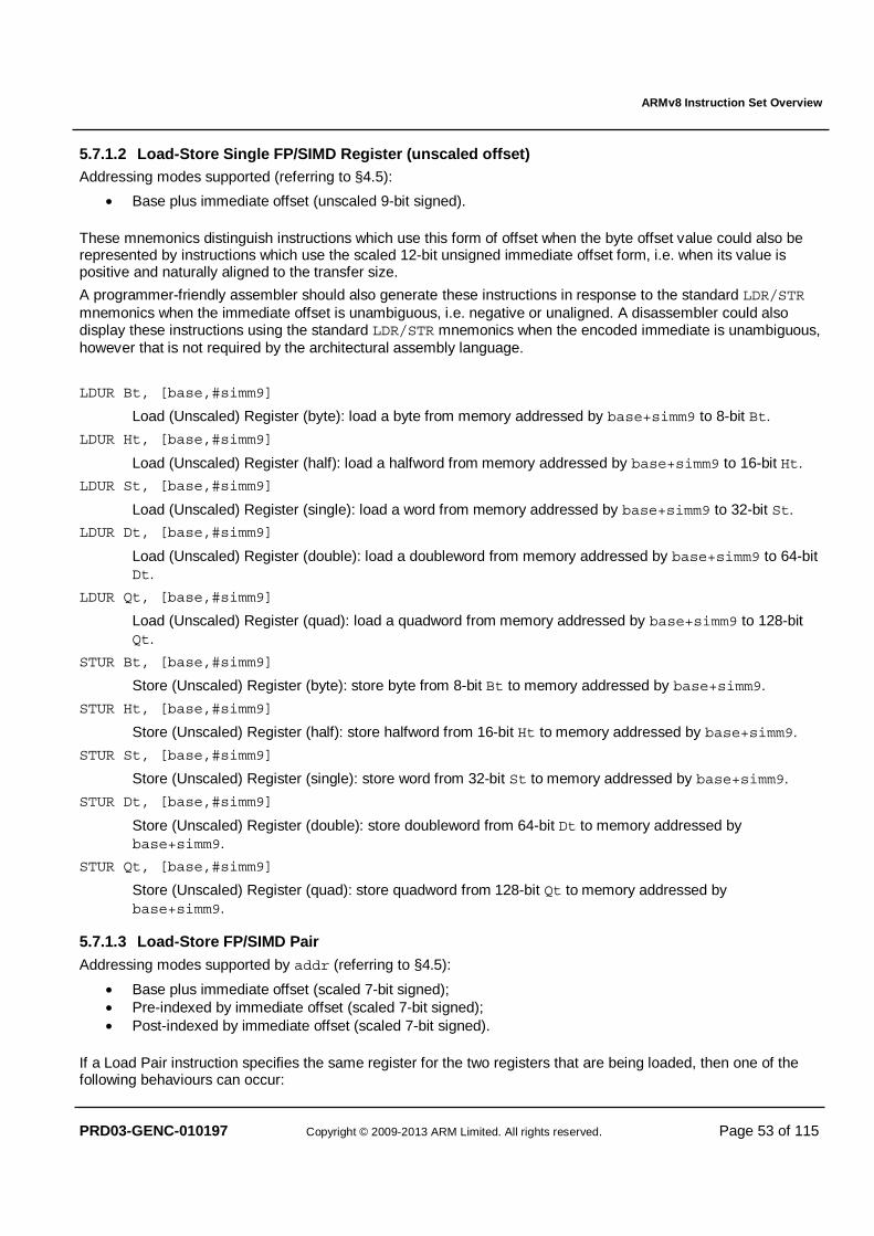
ARMv8 Instruction Set Overview
PRD03-GENC-010197 Copyright © 2009-2013 ARM Limited. All rights reserved. Page 53 of 115
5.7.1.2 Load-Store Single FP/SIMD Register (unscaled offset) Addressing modes supported (referring to §4.5):
• Base plus immediate offset (unscaled 9-bit signed).
These mnemonics distinguish instructions which use this form of offset when the byte offset value could also be represented by instructions which use the scaled 12-bit unsigned immediate offset form, i.e. when its value is positive and naturally aligned to the transfer size.
A programmer-friendly assembler should also generate these instructions in response to the standard LDR/STR mnemonics when the immediate offset is unambiguous, i.e. negative or unaligned. A disassembler could also display these instructions using the standard LDR/STR mnemonics when the encoded immediate is unambiguous, however that is not required by the architectural assembly language.
LDUR Bt, [base,#simm9]
Load (Unscaled) Register (byte): load a byte from memory addressed by base+simm9 to 8-bit Bt.
LDUR Ht, [base,#simm9]
Load (Unscaled) Register (half): load a halfword from memory addressed by base+simm9 to 16-bit Ht.
LDUR St, [base,#simm9]
Load (Unscaled) Register (single): load a word from memory addressed by base+simm9 to 32-bit St.
LDUR Dt, [base,#simm9]
Load (Unscaled) Register (double): load a doubleword from memory addressed by base+simm9 to 64-bit Dt.
LDUR Qt, [base,#simm9]
Load (Unscaled) Register (quad): load a quadword from memory addressed by base+simm9 to 128-bit Qt.
STUR Bt, [base,#simm9]
Store (Unscaled) Register (byte): store byte from 8-bit Bt to memory addressed by base+simm9.
STUR Ht, [base,#simm9]
Store (Unscaled) Register (half): store halfword from 16-bit Ht to memory addressed by base+simm9.
STUR St, [base,#simm9]
Store (Unscaled) Register (single): store word from 32-bit St to memory addressed by base+simm9.
STUR Dt, [base,#simm9]
Store (Unscaled) Register (double): store doubleword from 64-bit Dt to memory addressed by base+simm9.
STUR Qt, [base,#simm9]
Store (Unscaled) Register (quad): store quadword from 128-bit Qt to memory addressed by base+simm9.
5.7.1.3 Load-Store FP/SIMD Pair Addressing modes supported by addr (referring to §4.5):
• Base plus immediate offset (scaled 7-bit signed); • Pre-indexed by immediate offset (scaled 7-bit signed); • Post-indexed by immediate offset (scaled 7-bit signed).
If a Load Pair instruction specifies the same register for the two registers that are being loaded, then one of the following behaviours can occur:
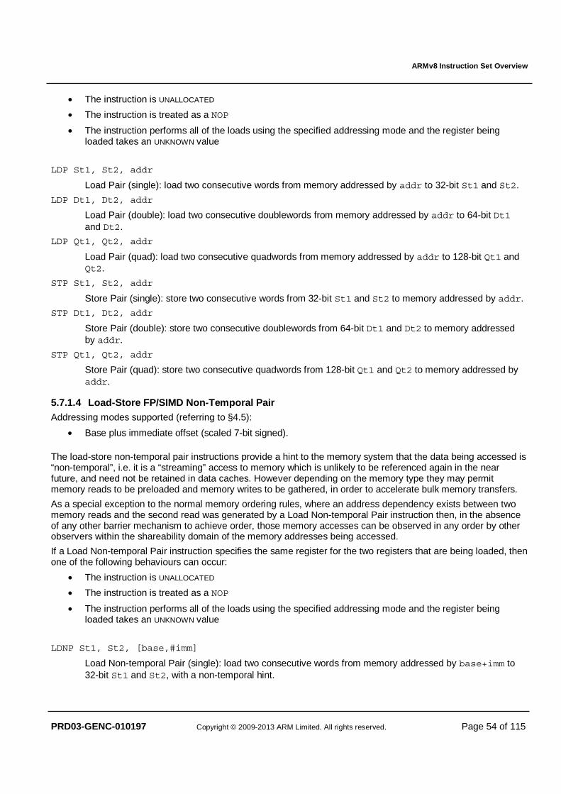
ARMv8 Instruction Set Overview
PRD03-GENC-010197 Copyright © 2009-2013 ARM Limited. All rights reserved. Page 54 of 115
• The instruction is UNALLOCATED
• The instruction is treated as a NOP
• The instruction performs all of the loads using the specified addressing mode and the register being loaded takes an UNKNOWN value
LDP St1, St2, addr
Load Pair (single): load two consecutive words from memory addressed by addr to 32-bit St1 and St2.
LDP Dt1, Dt2, addr
Load Pair (double): load two consecutive doublewords from memory addressed by addr to 64-bit Dt1 and Dt2.
LDP Qt1, Qt2, addr
Load Pair (quad): load two consecutive quadwords from memory addressed by addr to 128-bit Qt1 and Qt2.
STP St1, St2, addr
Store Pair (single): store two consecutive words from 32-bit St1 and St2 to memory addressed by addr.
STP Dt1, Dt2, addr
Store Pair (double): store two consecutive doublewords from 64-bit Dt1 and Dt2 to memory addressed by addr.
STP Qt1, Qt2, addr
Store Pair (quad): store two consecutive quadwords from 128-bit Qt1 and Qt2 to memory addressed by addr.
5.7.1.4 Load-Store FP/SIMD Non-Temporal Pair Addressing modes supported (referring to §4.5):
• Base plus immediate offset (scaled 7-bit signed).
The load-store non-temporal pair instructions provide a hint to the memory system that the data being accessed is “non-temporal”, i.e. it is a “streaming” access to memory which is unlikely to be referenced again in the near future, and need not be retained in data caches. However depending on the memory type they may permit memory reads to be preloaded and memory writes to be gathered, in order to accelerate bulk memory transfers.
As a special exception to the normal memory ordering rules, where an address dependency exists between two memory reads and the second read was generated by a Load Non-temporal Pair instruction then, in the absence of any other barrier mechanism to achieve order, those memory accesses can be observed in any order by other observers within the shareability domain of the memory addresses being accessed.
If a Load Non-temporal Pair instruction specifies the same register for the two registers that are being loaded, then one of the following behaviours can occur:
• The instruction is UNALLOCATED
• The instruction is treated as a NOP
• The instruction performs all of the loads using the specified addressing mode and the register being loaded takes an UNKNOWN value
LDNP St1, St2, [base,#imm]
Load Non-temporal Pair (single): load two consecutive words from memory addressed by base+imm to 32-bit St1 and St2, with a non-temporal hint.
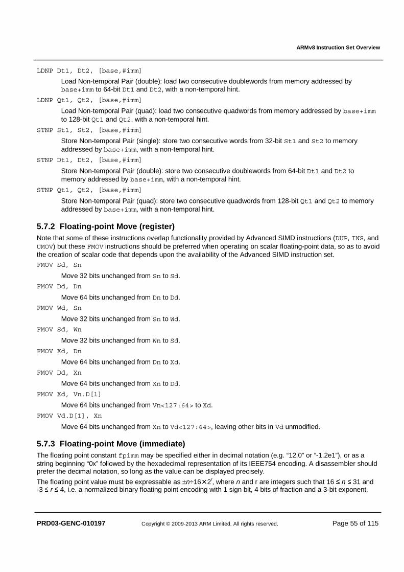
ARMv8 Instruction Set Overview
PRD03-GENC-010197 Copyright © 2009-2013 ARM Limited. All rights reserved. Page 55 of 115
LDNP Dt1, Dt2, [base,#imm]
Load Non-temporal Pair (double): load two consecutive doublewords from memory addressed by base+imm to 64-bit Dt1 and Dt2, with a non-temporal hint.
LDNP Qt1, Qt2, [base,#imm]
Load Non-temporal Pair (quad): load two consecutive quadwords from memory addressed by base+imm to 128-bit Qt1 and Qt2, with a non-temporal hint.
STNP St1, St2, [base,#imm]
Store Non-temporal Pair (single): store two consecutive words from 32-bit St1 and St2 to memory addressed by base+imm, with a non-temporal hint.
STNP Dt1, Dt2, [base,#imm]
Store Non-temporal Pair (double): store two consecutive doublewords from 64-bit Dt1 and Dt2 to memory addressed by base+imm, with a non-temporal hint.
STNP Qt1, Qt2, [base,#imm]
Store Non-temporal Pair (quad): store two consecutive quadwords from 128-bit Qt1 and Qt2 to memory addressed by base+imm, with a non-temporal hint.
5.7.2 Floating-point Move (register) Note that some of these instructions overlap functionality provided by Advanced SIMD instructions (DUP, INS, and UMOV) but these FMOV instructions should be preferred when operating on scalar floating-point data, so as to avoid the creation of scalar code that depends upon the availability of the Advanced SIMD instruction set.
FMOV Sd, Sn
Move 32 bits unchanged from Sn to Sd.
FMOV Dd, Dn
Move 64 bits unchanged from Dn to Dd.
FMOV Wd, Sn
Move 32 bits unchanged from Sn to Wd.
FMOV Sd, Wn
Move 32 bits unchanged from Wn to Sd.
FMOV Xd, Dn
Move 64 bits unchanged from Dn to Xd.
FMOV Dd, Xn
Move 64 bits unchanged from Xn to Dd.
FMOV Xd, Vn.D[1]
Move 64 bits unchanged from Vn<127:64> to Xd.
FMOV Vd.D[1], Xn
Move 64 bits unchanged from Xn to Vd<127:64>, leaving other bits in Vd unmodified.
5.7.3 Floating-point Move (immediate) The floating point constant fpimm may be specified either in decimal notation (e.g. “12.0” or “-1.2e1”), or as a string beginning “0x” followed by the hexadecimal representation of its IEEE754 encoding. A disassembler should prefer the decimal notation, so long as the value can be displayed precisely.
The floating point value must be expressable as ±n÷16�2r, where n and r are integers such that 16 ≤ n ≤ 31 and -3 ≤ r ≤ 4, i.e. a normalized binary floating point encoding with 1 sign bit, 4 bits of fraction and a 3-bit exponent.
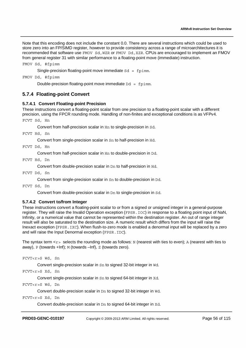
ARMv8 Instruction Set Overview
PRD03-GENC-010197 Copyright © 2009-2013 ARM Limited. All rights reserved. Page 56 of 115
Note that this encoding does not include the constant 0.0. There are several instructions which could be used to store zero into an FP/SIMD register, however to provide consistency across a range of microarchitectures it is recommended that software use FMOV Sd,WZR or FMOV Dd,XZR. CPUs are encouraged to implement an FMOV from general register 31 with similar performance to a floating-point move (immediate) instruction.
FMOV Sd, #fpimm
Single-precision floating-point move immediate Sd = fpimm.
FMOV Dd, #fpimm
Double-precision floating-point move immediate Dd = fpimm.
5.7.4 Floating-point Convert
5.7.4.1 Convert Floating-point Precision These instructions convert a floating-point scalar from one precision to a floating-point scalar with a different precision, using the FPCR rounding mode. Handling of non-finites and exceptional conditions is as VFPv4. FCVT Sd, Hn
Convert from half-precision scalar in Hn to single-precision in Sd.
FCVT Hd, Sn
Convert from single-precision scalar in Sn to half-precision in Hd.
FCVT Dd, Hn
Convert from half-precision scalar in Hn to double-precision in Dd.
FCVT Hd, Dn
Convert from double-precision scalar in Dn to half-precision in Hd.
FCVT Dd, Sn
Convert from single-precision scalar in Sn to double-precision in Dd.
FCVT Sd, Dn
Convert from double-precision scalar in Dn to single-precision in Sd.
5.7.4.2 Convert to/from Integer These instructions convert a floating-point scalar to or from a signed or unsigned integer in a general-purpose register. They will raise the Invalid Operation exception (FPSR.IOC) in response to a floating point input of NaN, Infinity, or a numerical value that cannot be represented within the destination register. An out of range integer result will also be saturated to the destination size. A numeric result which differs from the input will raise the Inexact exception (FPSR.IXC). When flush-to-zero mode is enabled a denormal input will be replaced by a zero and will raise the Input Denormal exception (FPSR.IDC). The syntax term <r> selects the rounding mode as follows: N (nearest with ties to even); A (nearest with ties to away), P (towards +Inf); M (towards –Inf), Z (towards zero).
FCVT<r>S Wd, Sn
Convert single-precision scalar in Sn to signed 32-bit integer in Wd.
FCVT<r>S Xd, Sn
Convert single-precision scalar in Sn to signed 64-bit integer in Xd.
FCVT<r>S Wd, Dn
Convert double-precision scalar in Dn to signed 32-bit integer in Wd.
FCVT<r>S Xd, Dn
Convert double-precision scalar in Dn to signed 64-bit integer in Xd.
ARMv8 Instruction Set Overview
PRD03-GENC-010197 Copyright © 2009-2013 ARM Limited. All rights reserved. Page 57 of 115
FCVT<r>U Wd, Sn
Convert single-precision scalar in Sn to unsigned 32-bit integer in Wd.
FCVT<r>U Xd, Sn
Convert single-precision scalar in Sn to unsigned 64-bit integer in Xd.
FCVT<r>U Wd, Dn
Convert double-precision scalar in Dn to unsigned 32-bit integer in Wd.
FCVT<r>U Xd, Dn
Convert double-precision scalar in Dn to unsigned 64-bit integer in Xd.
SCVTF Sd, Wn
Convert signed 32-bit integer in Wn to single-precision scalar in Sd, using FPCR rounding mode.
SCVTF Sd, Xn
Convert signed 64-bit integer in Xn to single-precision scalar in Sd, using FPCR rounding mode.
SCVTF Dd, Wn
Convert signed 32-bit integer in Wn to double-precision scalar in Dd, using FPCR rounding mode.
SCVTF Dd, Xn
Convert signed 64-bit integer in Xn to double-precision scalar in Dd, using FPCR rounding mode.
UCVTF Sd, Wn
Convert unsigned 32-bit integer in Wn to single-precision scalar in Sd, using FPCR rounding mode.
UCVTF Sd, Xn
Convert unsigned 64-bit integer in Xn to single-precision scalar in Sd, using FPCR rounding mode.
UCVTF Dd, Wn
Convert unsigned 32-bit integer in Wn to double-precision scalar in Dd, using FPCR rounding mode.
UCVTF Dd, Xn
Convert unsigned 64-bit integer in Xn to double-precision scalar in Dd, using FPCR rounding mode.
5.7.4.3 Convert to/from Fixed-point These instructions convert a floating-point scalar to or from a signed or unsigned fixed-point value in a general-purpose register. The #fbits operand indicates that the general register holds a fixed-point number with fbits bits after the binary point, where fbits is in the range 1 to 32 for a 32-bit general register, or 1 to 64 for a 64-bit general register. The instructions raise the Invalid Operation exception (FPSR.IOC) in response to a floating point input of NaN, Infinity, or a numerical value that cannot be represented within the destination register. An out of range fixed-point result will also be saturated to the destination size. A numeric result which differs from the input will raise the Inexact exception (FPSR.IXC). When flush-to-zero mode is enabled a denormal input will be replaced by a zero and will raise the Input Denormal exception (FPSR.IDC).
FCVTZS Wd, Sn, #fbits
Convert single-precision scalar in Sn to signed 32-bit fixed-point in Wd, rounding towards zero.
FCVTZS Xd, Sn, #fbits
Convert single-precision scalar in Sn to signed 64-bit fixed-point in Xd, rounding towards zero.
FCVTZS Wd, Dn, #fbits
Convert double-precision scalar in Dn to signed 32-bit fixed-point in Wd, rounding towards zero.
ARMv8 Instruction Set Overview
PRD03-GENC-010197 Copyright © 2009-2013 ARM Limited. All rights reserved. Page 58 of 115
FCVTZS Xd, Dn, #fbits
Convert double-precision scalar in Dn to signed 64-bit fixed-point in Xd, rounding towards zero.
FCVTZU Wd, Sn, #fbits
Convert single-precision scalar in Sn to unsigned 32-bit fixed-point in Wd, rounding towards zero.
FCVTZU Xd, Sn, #fbits
Convert single-precision scalar in Sn to unsigned 64-bit fixed-point in Xd, rounding towards zero.
FCVTZU Wd, Dn, #fbits
Convert double-precision scalar in Dn to unsigned 32-bit fixed-point in Wd, rounding towards zero.
FCVTZU Xd, Dn, #fbits
Convert double-precision scalar in Dn to unsigned 64-bit fixed-point in Xd, rounding towards zero.
SCVTF Sd, Wn, #fbits
Convert signed 32-bit fixed-point in Wn to single-precision scalar in Sd, using FPCR rounding mode.
SCVTF Sd, Xn, #fbits
Convert signed 64-bit fixed-point in Xn to single-precision scalar in Sd, using FPCR rounding mode.
SCVTF Dd, Wn, #fbits
Convert signed 32-bit fixed-point in Wn to double-precision scalar in Dd, using FPCR rounding mode.
SCVTF Dd, Xn, #fbits
Convert signed 64-bit fixed-point in Xn to double-precision scalar in Dd, using FPCR rounding mode.
UCVTF Sd, Wn, #fbits
Convert unsigned 32-bit fixed-point in Wn to single-precision scalar in Sd, using FPCR rounding mode.
UCVTF Sd, Xn, #fbits
Convert unsigned 64-bit fixed-point in Xn to single-precision scalar in Sd, using FPCR rounding mode.
UCVTF Dd, Wn, #fbits
Convert unsigned 32-bit fixed-point in Wn to double-precision scalar in Dd, using FPCR rounding mode.
UCVTF Dd, Xn, #fbits
Convert unsigned 64-bit fixed-point in Xn to double-precision scalar in Dd, using FPCR rounding mode.
5.7.5 Floating-point Round to Integral The round to integral instructions round a floating-point value to an integral floating-point value of the same size. The only FPSR exception flags that can be raised by these instructions are: FPSR.IOC (Invalid Operation) for a Signaling NaN input; FPSR.IDC (Input Denormal) for a denormal input when flush-to-zero mode is enabled; for FRINTX only the FPSR.IXC (Inexact) exception if the result is numeric and does not have the same numerical value as the source. A zero input gives a zero result with the same sign, an infinite input gives an infinite result with the same sign, and a NaN is propagated as in normal arithmetic. The syntax term <r> selects the rounding mode as follows: N (nearest with ties to even); A (nearest with ties to away), P (towards +Inf); M (towards –Inf), Z (towards zero), I (using FPCR rounding mode) and X (using FPCR rounding mode, with exactness check).
FRINT<r> Sd, Sn
Single-precision floating-point scalar round to integral from Sn to Sd.
FRINT<r> Dd, Dn
Double-precision floating-point scalar round to integral from Dn to Dd.
ARMv8 Instruction Set Overview
PRD03-GENC-010197 Copyright © 2009-2013 ARM Limited. All rights reserved. Page 59 of 115
5.7.6 Floating-point Arithmetic (1 source) FABS Sd, Sn
Single-precision floating-point scalar absolute value: Sd = abs(Sn).
FABS Dd, Dn
Double-precision floating-point scalar absolute value: Dd = abs(Dn).
FNEG Sd, Sn
Single-precision floating-point scalar negation: Sd = -Sn.
FNEG Dd, Dn
Double-precision floating-point scalar negation: Dd = -Dn.
FSQRT Sd, Sn
Single-precision floating-point scalar square root: Sd = sqrt(Sn).
FSQRT Dd, Dn
Double-precision floating-point scalar square root: Dd = sqrt(Dn).
5.7.7 Floating-point Arithmetic (2 source) FADD Sd, Sn, Sm
Single-precision floating-point scalar add: Sd = Sn + Sm.
FADD Dd, Dn, Dm
Double-precision floating-point scalar add: Dd = Dn + Dm.
FDIV Sd, Sn, Sm
Single-precision floating-point scalar divide: Sd = Sn / Sm.
FDIV Dd, Dn, Dm
Double-precision floating-point scalar divide: Dd = Dn / Dm.
FMUL Sd, Sn, Sm
Single-precision floating-point scalar multiply: Sd = Sn * Sm.
FMUL Dd, Dn, Dm
Double-precision floating-point scalar multipy: Dd = Dn * Dm.
FNMUL Sd, Sn, Sm
Single-precision floating-point scalar multiply-negate: Sd = -(Sn * Sm).
FNMUL Dd, Dn, Dm
Double-precision floating-point scalar multiply-negate: Dd = -(Dn * Dm).
FSUB Sd, Sn, Sm
Single-precision floating-point scalar subtract: Sd = Sn - Sm.
FSUB Dd, Dn, Dm
Double-precision floating-point scalar subtract: Dd = Dn - Dm.
5.7.8 Floating-point Min/Max The min(x,y) and max(x,y) operations behave similarly to the ARM v7 VMIN.F and VMAX.F instructions and return a quiet NaN when either x or y is a NaN. In flush-to-zero mode subnormal operands are flushed to zero before comparison, and if a flushed value is then the appropriate result the zero value is returned. Where both x and y are zero (or subnormal values flushed to zero) with differing sign, then +0.0 is returned by max() and -0.0 by min().
ARMv8 Instruction Set Overview
PRD03-GENC-010197 Copyright © 2009-2013 ARM Limited. All rights reserved. Page 60 of 115
The minNum(x,y) and maxNum(x,y) operations follow the IEEE 754-2008 standard and return the numerical operand when one operand is numerical and the other a quiet NaN. Apart from this additional handling of a single quiet NaN the result is then identical to min(x,y) and max(x,y).
FMAX Sd, Sn, Sm
Single-precision floating-point scalar maximum: Sd = max(Sn,Sm).
FMAX Dd, Dn, Dm
Double-precision floating-point scalar maximum: Dd = max(Dn,Dm).
FMAXNM Sd, Sn, Sm
Single-precision floating-point scalar maximum number: Sd = maxNum(Sn,Sm).
FMAXNM Dd, Dn, Dm
Double-precision floating-point scalar maximum number: Dd = maxNum(Dn,Dm).
FMIN Sd, Sn, Sm
Single-precision floating-point scalar minimum: Sd = min(Sn,Sm).
FMIN Dd, Dn, Dm
Double-precision floating-point scalar minimum: Dd = min(Dn,Dm).
FMINNM Sd, Sn, Sm
Single-precision floating-point scalar minimum number: Sd = minNum(Sn,Sm).
FMINNM Dd, Dn, Dm
Double-precision floating-point scalar minimum number: Dd = minNum(Dn,Dm).
5.7.9 Floating-point Multiply-Add FMADD Sd, Sn, Sm, Sa
Single-precision floating-point scalar fused multiply-add: Sd = Sa + Sn*Sm.
FMADD Dd, Dn, Dm, Da
Double-precision floating-point scalar fused multiply-add: Dd = Da + Dn*Dm.
FMSUB Sd, Sn, Sm, Sa
Single-precision floating-point scalar fused multiply-subtract: Sd = Sa + (-Sn)*Sm.
FMSUB Dd, Dn, Dm, Da
Double-precision floating-point scalar fused multiply-subtract: Dd = Da + (-Dn)*Dm.
FNMADD Sd, Sn, Sm, Sa
Single-precision floating-point scalar negated fused multiply-add: Sd = (-Sa) + (-Sn)*Sm.
FNMADD Dd, Dn, Dm, Da
Double-precision floating-point scalar negated fused multiply-add: Dd = (-Da) + (-Dn)*Dm.
FNMSUB Sd, Sn, Sm, Sa
Single-precision floating-point scalar negated fused multiply-subtract: Sd = (-Sa) + Sn*Sm.
FNMSUB Dd, Dn, Dm, Da
Double-precision floating-point scalar negated fused multiply-subtract: Dd = (-Da) + Dn*Dm.
5.7.10 Floating-point Comparison These instructions set the integer NZCV condition flags directly, and do not alter the condition flags in the FPSR. In the conditional compare instructions, the #uimm4 operand is a bitmask used to set the NZCV flags when the input condition is false, with bit 3 setting the N flag, bit 2 the Z flag, bit 1 the C flag, and bit 0 the V flag. If floating-point comparisons are unordered the C and V flag bits are set and the N and Z bits cleared.
ARMv8 Instruction Set Overview
PRD03-GENC-010197 Copyright © 2009-2013 ARM Limited. All rights reserved. Page 61 of 115
FCMP Sn, Sm|#0.0
Single-precision compare: set condition flags from floating point comparison of Sn with Sm or 0.0. Invalid Operation exception only on signaling NaNs.
FCMP Dn, Dm|#0.0
Double-precision compare: set condition flags from floating point comparison of Dn with Dm or 0.0. Invalid Operation exception only on signaling NaNs.
FCMPE Sn, Sm|#0.0
Single-precision compare, exceptional: set flags from floating point comparison of Sn with Sm or 0.0. Invalid Operation exception on all NaNs.
FCMPE Dn, Dm|#0.0
Double-precision compare, exceptional: set flags from floating point comparison of Dn with Dm or 0.0. Invalid Operation exception on all NaNs.
FCCMP Sn, Sm, #uimm4, cond
Single-precision conditional compare: NZCV = if cond then FPCompare(Sn, Sm) else uimm4. Invalid Operation exception only on signaling NaNs when cond holds true.
FCCMP Dn, Dm, #uimm4, cond
Double-precision conditional compare: NZCV = if cond then FPcompare(Dn, Dm) else uimm4. Invalid Operation exception only on signaling NaNs when cond holds true.
FCCMPE Sn, Sm, #uimm4, cond
Single-precision conditional compare, exceptional: NZCV = if cond then FPCompare(Sn, Sm) else uimm4. Invalid Operation exception on all NaNs when cond holds true.
FCCMPE Dn, Dm, #uimm4, cond
Double-precision conditional compare, exceptional: NZCV = if cond then FPCompare(Dn, Dm) else uimm4. Invalid Operation exception on all NaNs when cond holds true.
5.7.11 Floating-point Conditional Select FCSEL Sd, Sn, Sm, cond
Single-precision conditional select: Sd = if cond then Sn else Sm.
FCSEL Dd, Dn, Dm, cond
Double-precision conditional select: Dd = if cond then Dn else Dm.
ARMv8 Instruction Set Overview
PRD03-GENC-010197 Copyright © 2009-2013 ARM Limited. All rights reserved. Page 62 of 115
5.8 Advanced SIMD
5.8.1 Overview AArch64 Advanced SIMD is based upon the existing AArch32 Advanced SIMD extension, with the following changes:
• In AArch64 Advanced SIMD, there are thirty two 128-bit wide vector registers, whereas AArch32 Advanced SIMD had sixteen 128-bit wide registers.
• There are thirty two 64-bit vectors and these are held in the lower 64 bits of each 128-bit register.
• Writes of 64 bits or less to a vector register result in the higher bits being zeroed (except for lane inserts).
• New lane insert and extract instructions have been added to support the new register packing scheme.
• Additional widening instructions are provided for generating the top 64 bits of a 128-bit vector register.
• Data-processing instructions which would generate more than one result register (e.g. widening to a 256-bit vector), or consume more than three sources (e.g. narrowing to a 128-bit vector), have been split into separate instructions.
• A set of scalar instructions have been added to implement loop heads and tails, but only where the instruction does not already exist in the main scalar floating-point instruction set, and only when “over-computing” using a vector form might have the side effect of setting the saturation or floating point exception flags if there was “garbage” in unused higher lanes. Scalar operations on 64-bit integers are also provided in this section, to avoid the cost of over-computing using a 128-bit vector.
• A new set of vector “reduction” operations provide across-lane sum, minimum and maximum.
• Some existing instructions have been extended to support 64-bit integer values: e.g. comparison, addition, absolute value and negate, including saturating versions.
• Advanced SIMD now supports both single-precision (32-bit) and double-precision (64-bit) floating-point vector data types and arithmetic as defined by the IEEE 754 floating-point standard, honoring the FPCR Rounding Mode field, the Default NaN control, the Flush-to-Zero control, and (where supported by the implementation) the Exception trap enable bits.
• The ARMv7 SIMD "chained" floating-point multiply-accumulate instructions have been replaced with IEEE754 "fused" multiply-add. This includes the reciprocal step and reciprocal square root step instructions.
• Convert float to integer (FCVTxU, FCVTxS) encode a directed rounding mode: towards zero, towards +Inf, towards –Inf, nearest with ties to even, and nearest with ties to away.
• Round float to nearest integer in floating-point format (FRINTx) has been added, with the same directed rounding modes, as well as rounding according to the ambient rounding mode.
• A new double to single precision down-convert instruction with inexact “rounding to odd ", suitable for ongoing down-conversion to half-precision with correct rounding (FCVTXN).
• IEEE 754-2008 minNum() and maxNum() instructions have been added (FMINNM, FMAXNM).
• Instructions to accelerate floating point vector normalisation have been added (FRECPX, FMULX).
• Saturating instructions have been extended to include unsigned accumulate into signed, and vice-versa.
ARMv8 Instruction Set Overview
PRD03-GENC-010197 Copyright © 2009-2013 ARM Limited. All rights reserved. Page 63 of 115
5.8.2 Advanced SIMD Mnemonics Although derived from the AArch32 Advanced SIMD syntax, a number of changes have been made to harmonise with the AArch64 core integer and scalar floating point instruction set syntax, and to unify AArch32’s divergent “architectural” and “programmers’” notations:
• The ‘V’ mnemonic prefix has been removed, and S/U/F/P added to indicate signed/unsigned/floating-point/polynomial data type. The mnemonic always indicates the data type(s) of the operation.
• The vector organisation (element size and number of lanes) is described by the register qualifiers and never by a mnemonic qualifier. See the description of the vector register syntax in §4.4.2 above.
• The ‘P’ prefix for “pairwise” operations becomes a suffix.
• A ‘V’ suffix has been added for the new reduction (across-all-lanes) operations
• A ‘2’ suffix has been added for the new widening/narrowing “second part” instructions, described below.
• Vector compares now use the integer condition code names to indicate whether an integer comparison is signed or unsigned (e.g. CMLT, CMLO, CMGE, CMHI, etc)
• Some mnemonics have been renamed where the removal of the V prefix caused clash with the core instruction set mnemonics.
With the exception of the above changes, the mnemonics are based closely on AArch32 Advanced SIMD. As such, the learning curve for existing Advanced SIMD programmers is reduced. A full list of the equivalent AArch32 mnemonics can be found in §5.8.25 below.
Widening instructions with a ‘2’ suffix implement the “second” or “top” part of a widening operation that would otherwise need to write two 128-bit vectors: they get their input data from the high numbered lanes of the 128-bit source vectors, and write the expanded results to the 128-bit destination.
Narrowing instructions with a ‘2’ suffix implement the “second” or “top” part of a narrowing operation that would otherwise need to read two 128-bit vectors for each source operand: they get their input data from the 128-bit source operands and insert their narrowed results into the high numbered lanes of the 128-bit destination, leaving the lower lanes unchanged.
5.8.3 Data Movement Note that some of these instructions overlap functionality provided by the scalar floating-point FMOV instructions described in section 5.7.2. These Advanced SIMD instructions should be preferred unless the register is known to contain a value that will only be operated upon by scalar floating-point instructions.
DUP Vd.<Td>, Vn.<Ts>[index]
Duplicate element (vector). Replicate single vector element from Vn to all elements of Vd. Where <Td>/<Ts> may be 8B/B, 16B/B, 4H/H, 8H/H, 2S/S, 4S/S or 2D/D. The immediate index is a value in the range 0 to (16/sizeof(<Ts>))-1.
DUP Vd.<T>, Wn
Duplicate 32-bit general register (vector). Replicate low order bits from 32-bit general register Wn to all elements of vector Vd. Where <T> may be 8B, 16B, 4H, 8H, 2S or 4S.
DUP Vd.2D, Xn
Duplicate 64-bit general register (vector). Replicate 64-bit general register Xn to both elements of vector Vd.
DUP <V>d, Vn.<T>[index]
Duplicate element (scalar). Copy single vector element from Vn to scalar register <V>d. Where <V>/<T> may be B/B, H/H, S/S or D/D. The immediate index is a value in the range 0 to (16/sizeof(<T>))-1. Normally disassembled as MOV.
ARMv8 Instruction Set Overview
PRD03-GENC-010197 Copyright © 2009-2013 ARM Limited. All rights reserved. Page 64 of 115
INS Vd.<T>[index], Vn.<T>[index2]
Insert element (vector). Inserts a single vector element from Vn into a single element of Vd. Where <T> may be B, H, S or D. Both immediates index and index2 are values in the range 0 to (16/sizeof(<T>))-1. Normally disassembled as MOV.
INS Vd.<T>[index], Wn
Insert 32-bit general register (vector). Inserts low order bits from 32-bit general register Wn into a single vector element of Vd. Where <T> may be B, H or S. The immediate index is a value in the range 0 to (16/sizeof(<T>))-1. Normally disassembled as MOV.
INS Vd.D[index], Xn
Insert 64-bit general register (vector). Inserts 64-bit general register Xn into a single vector element of Vd. The immediate index is a value in the range 0 to 1. Normally disassembled as MOV.
MOV Vd.<T>[index], Vn.<T>[index2]
Move element. Moves a vector element from Vn to a vector element in Vd: alias for INS Vd.<T>[index],Vn.<T>[index2].
MOV Vd.<T>[index], Wn
Move 32-bit general register to element. Moves a 32-bit general register Wn to vector element in Vd: alias for INS Vd.<T>[index],Wn.
MOV Vd.2D[index], Xn
Move 64-bit general register to element. Moves a 64-bit general register Xn to a vector element in Vd: alias for INS Vd.D[index],Xn.
MOV <V>d, Vn.<T>[index]
Move element (scalar). Moves a vector element from Vn to scalar register <V>d: alias for DUP <V>d,Vn.<T>[index].
MOV <V>d, <V>n
Move (scalar). Moves a scalar register <V>n to scalar register <V>d: alias for DUP <V>d,Vn.<V>[0].
UMOV Wd, Vn.<T>[index]
Unsigned move element to 32-bit general register. Zero-extends an integer vector element from Vn into 32-bit general register Wd. Where <T> may be B, H or S. The index is in the range 0 to (16/sizeof(<T>))-1. Disassembled as MOV when <T> is S,
UMOV Xd, Vn.D[index]
Unsigned move element to 64-bit general register. Moves an unsigned 64-bit integer vector element from Vn into 64-bit general register Xd. The immediate index is in the range 0 to 1. Normally disassembled as MOV.
MOV Wd, Vn.S[index]
Move element to 32-bit general register. Moves a 32-bit vector element from Vn to 32-bit general register Wd: alias for UMOV Wd,Vn.S[index],
MOV Xd, Vn.D[index]
Move element to 64-bit general register. Moves a 64-bit vector element from Vn to 64-bit general register Xd: alias for UMOV Xd,Vn.D[index].
SMOV Wd, Vn.<T>[index]
Signed move element to 32-bit general register. Sign-extends an integer vector element from Vn into 32-bit general register Wd. Where <T> may be B or H. The index is a value is in the range 0 to (16/sizeof(<T>))-1.
SMOV Xd, Vn.<T>[index]
Signed move element to 64-bit general register. Sign-extends an integer vector element from Vn into 64-bit general register Xd. Where <T> may be B, H or S. The index is in the range 0 to (16/sizeof(<T>))-1.
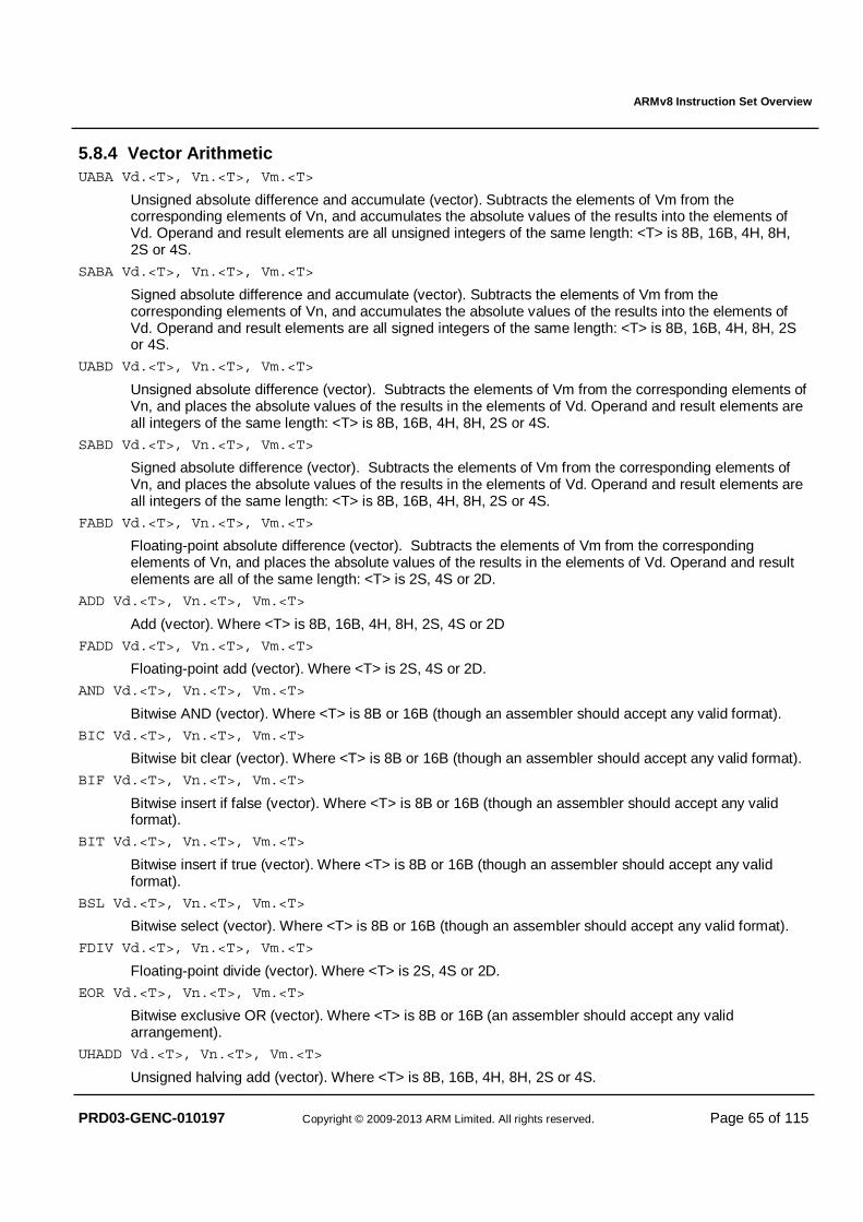
ARMv8 Instruction Set Overview
PRD03-GENC-010197 Copyright © 2009-2013 ARM Limited. All rights reserved. Page 65 of 115
5.8.4 Vector Arithmetic UABA Vd.<T>, Vn.<T>, Vm.<T>
Unsigned absolute difference and accumulate (vector). Subtracts the elements of Vm from the corresponding elements of Vn, and accumulates the absolute values of the results into the elements of Vd. Operand and result elements are all unsigned integers of the same length: <T> is 8B, 16B, 4H, 8H, 2S or 4S.
SABA Vd.<T>, Vn.<T>, Vm.<T>
Signed absolute difference and accumulate (vector). Subtracts the elements of Vm from the corresponding elements of Vn, and accumulates the absolute values of the results into the elements of Vd. Operand and result elements are all signed integers of the same length: <T> is 8B, 16B, 4H, 8H, 2S or 4S.
UABD Vd.<T>, Vn.<T>, Vm.<T>
Unsigned absolute difference (vector). Subtracts the elements of Vm from the corresponding elements of Vn, and places the absolute values of the results in the elements of Vd. Operand and result elements are all integers of the same length: <T> is 8B, 16B, 4H, 8H, 2S or 4S.
SABD Vd.<T>, Vn.<T>, Vm.<T>
Signed absolute difference (vector). Subtracts the elements of Vm from the corresponding elements of Vn, and places the absolute values of the results in the elements of Vd. Operand and result elements are all integers of the same length: <T> is 8B, 16B, 4H, 8H, 2S or 4S.
FABD Vd.<T>, Vn.<T>, Vm.<T>
Floating-point absolute difference (vector). Subtracts the elements of Vm from the corresponding elements of Vn, and places the absolute values of the results in the elements of Vd. Operand and result elements are all of the same length: <T> is 2S, 4S or 2D.
ADD Vd.<T>, Vn.<T>, Vm.<T>
Add (vector). Where <T> is 8B, 16B, 4H, 8H, 2S, 4S or 2D
FADD Vd.<T>, Vn.<T>, Vm.<T>
Floating-point add (vector). Where <T> is 2S, 4S or 2D.
AND Vd.<T>, Vn.<T>, Vm.<T>
Bitwise AND (vector). Where <T> is 8B or 16B (though an assembler should accept any valid format).
BIC Vd.<T>, Vn.<T>, Vm.<T>
Bitwise bit clear (vector). Where <T> is 8B or 16B (though an assembler should accept any valid format).
BIF Vd.<T>, Vn.<T>, Vm.<T>
Bitwise insert if false (vector). Where <T> is 8B or 16B (though an assembler should accept any valid format).
BIT Vd.<T>, Vn.<T>, Vm.<T>
Bitwise insert if true (vector). Where <T> is 8B or 16B (though an assembler should accept any valid format).
BSL Vd.<T>, Vn.<T>, Vm.<T>
Bitwise select (vector). Where <T> is 8B or 16B (though an assembler should accept any valid format).
FDIV Vd.<T>, Vn.<T>, Vm.<T>
Floating-point divide (vector). Where <T> is 2S, 4S or 2D.
EOR Vd.<T>, Vn.<T>, Vm.<T>
Bitwise exclusive OR (vector). Where <T> is 8B or 16B (an assembler should accept any valid arrangement).
UHADD Vd.<T>, Vn.<T>, Vm.<T>
Unsigned halving add (vector). Where <T> is 8B, 16B, 4H, 8H, 2S or 4S.
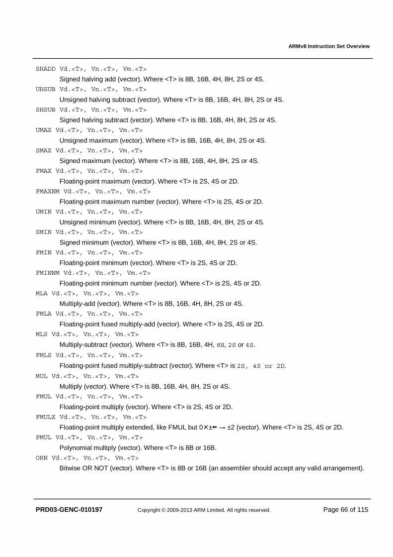
ARMv8 Instruction Set Overview
PRD03-GENC-010197 Copyright © 2009-2013 ARM Limited. All rights reserved. Page 66 of 115
SHADD Vd.<T>, Vn.<T>, Vm.<T>
Signed halving add (vector). Where <T> is 8B, 16B, 4H, 8H, 2S or 4S.
UHSUB Vd.<T>, Vn.<T>, Vm.<T>
Unsigned halving subtract (vector). Where <T> is 8B, 16B, 4H, 8H, 2S or 4S.
SHSUB Vd.<T>, Vn.<T>, Vm.<T>
Signed halving subtract (vector). Where <T> is 8B, 16B, 4H, 8H, 2S or 4S.
UMAX Vd.<T>, Vn.<T>, Vm.<T>
Unsigned maximum (vector). Where <T> is 8B, 16B, 4H, 8H, 2S or 4S.
SMAX Vd.<T>, Vn.<T>, Vm.<T>
Signed maximum (vector). Where <T> is 8B, 16B, 4H, 8H, 2S or 4S.
FMAX Vd.<T>, Vn.<T>, Vm.<T>
Floating-point maximum (vector). Where <T> is 2S, 4S or 2D.
FMAXNM Vd.<T>, Vn.<T>, Vm.<T>
Floating-point maximum number (vector). Where <T> is 2S, 4S or 2D.
UMIN Vd.<T>, Vn.<T>, Vm.<T>
Unsigned minimum (vector). Where <T> is 8B, 16B, 4H, 8H, 2S or 4S. SMIN Vd.<T>, Vn.<T>, Vm.<T>
Signed minimum (vector). Where <T> is 8B, 16B, 4H, 8H, 2S or 4S.
FMIN Vd.<T>, Vn.<T>, Vm.<T>
Floating-point minimum (vector). Where <T> is 2S, 4S or 2D.
FMINNM Vd.<T>, Vn.<T>, Vm.<T>
Floating-point minimum number (vector). Where <T> is 2S, 4S or 2D.
MLA Vd.<T>, Vn.<T>, Vm.<T>
Multiply-add (vector). Where <T> is 8B, 16B, 4H, 8H, 2S or 4S.
FMLA Vd.<T>, Vn.<T>, Vm.<T>
Floating-point fused multiply-add (vector). Where <T> is 2S, 4S or 2D.
MLS Vd.<T>, Vn.<T>, Vm.<T>
Multiply-subtract (vector). Where <T> is 8B, 16B, 4H, 8H, 2S or 4S.
FMLS Vd.<T>, Vn.<T>, Vm.<T>
Floating-point fused multiply-subtract (vector). Where <T> is 2S, 4S or 2D.
MUL Vd.<T>, Vn.<T>, Vm.<T>
Multiply (vector). Where <T> is 8B, 16B, 4H, 8H, 2S or 4S.
FMUL Vd.<T>, Vn.<T>, Vm.<T>
Floating-point multiply (vector). Where <T> is 2S, 4S or 2D.
FMULX Vd.<T>, Vn.<T>, Vm.<T>
Floating-point multiply extended, like FMUL but 0�±∞ → ±2 (vector). Where <T> is 2S, 4S or 2D.
PMUL Vd.<T>, Vn.<T>, Vm.<T>
Polynomial multiply (vector). Where <T> is 8B or 16B.
ORN Vd.<T>, Vn.<T>, Vm.<T>
Bitwise OR NOT (vector). Where <T> is 8B or 16B (an assembler should accept any valid arrangement).
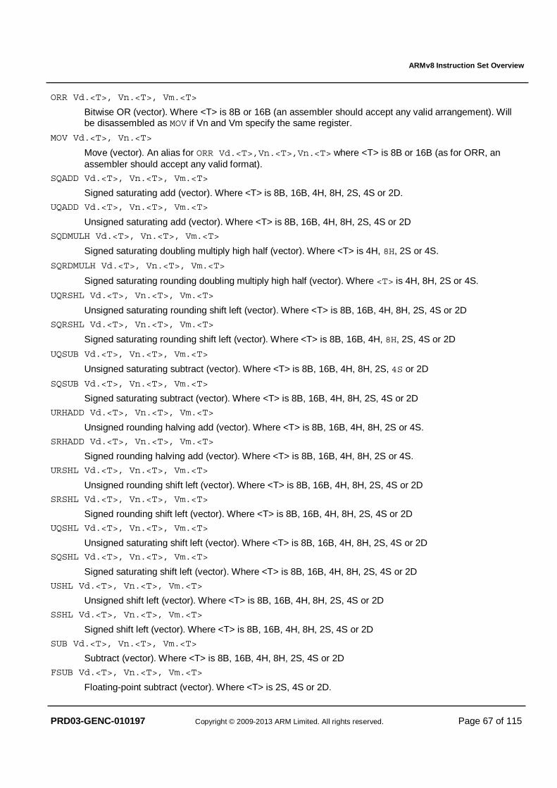
ARMv8 Instruction Set Overview
PRD03-GENC-010197 Copyright © 2009-2013 ARM Limited. All rights reserved. Page 67 of 115
ORR Vd.<T>, Vn.<T>, Vm.<T>
Bitwise OR (vector). Where <T> is 8B or 16B (an assembler should accept any valid arrangement). Will be disassembled as MOV if Vn and Vm specify the same register.
MOV Vd.<T>, Vn.<T>
Move (vector). An alias for ORR Vd.<T>,Vn.<T>,Vn.<T> where <T> is 8B or 16B (as for ORR, an assembler should accept any valid format).
SQADD Vd.<T>, Vn.<T>, Vm.<T>
Signed saturating add (vector). Where <T> is 8B, 16B, 4H, 8H, 2S, 4S or 2D.
UQADD Vd.<T>, Vn.<T>, Vm.<T>
Unsigned saturating add (vector). Where <T> is 8B, 16B, 4H, 8H, 2S, 4S or 2D
SQDMULH Vd.<T>, Vn.<T>, Vm.<T>
Signed saturating doubling multiply high half (vector). Where <T> is 4H, 8H, 2S or 4S.
SQRDMULH Vd.<T>, Vn.<T>, Vm.<T>
Signed saturating rounding doubling multiply high half (vector). Where <T> is 4H, 8H, 2S or 4S.
UQRSHL Vd.<T>, Vn.<T>, Vm.<T>
Unsigned saturating rounding shift left (vector). Where <T> is 8B, 16B, 4H, 8H, 2S, 4S or 2D
SQRSHL Vd.<T>, Vn.<T>, Vm.<T>
Signed saturating rounding shift left (vector). Where <T> is 8B, 16B, 4H, 8H, 2S, 4S or 2D
UQSUB Vd.<T>, Vn.<T>, Vm.<T>
Unsigned saturating subtract (vector). Where <T> is 8B, 16B, 4H, 8H, 2S, 4S or 2D
SQSUB Vd.<T>, Vn.<T>, Vm.<T>
Signed saturating subtract (vector). Where <T> is 8B, 16B, 4H, 8H, 2S, 4S or 2D
URHADD Vd.<T>, Vn.<T>, Vm.<T>
Unsigned rounding halving add (vector). Where <T> is 8B, 16B, 4H, 8H, 2S or 4S.
SRHADD Vd.<T>, Vn.<T>, Vm.<T>
Signed rounding halving add (vector). Where <T> is 8B, 16B, 4H, 8H, 2S or 4S.
URSHL Vd.<T>, Vn.<T>, Vm.<T>
Unsigned rounding shift left (vector). Where <T> is 8B, 16B, 4H, 8H, 2S, 4S or 2D
SRSHL Vd.<T>, Vn.<T>, Vm.<T>
Signed rounding shift left (vector). Where <T> is 8B, 16B, 4H, 8H, 2S, 4S or 2D
UQSHL Vd.<T>, Vn.<T>, Vm.<T>
Unsigned saturating shift left (vector). Where <T> is 8B, 16B, 4H, 8H, 2S, 4S or 2D SQSHL Vd.<T>, Vn.<T>, Vm.<T>
Signed saturating shift left (vector). Where <T> is 8B, 16B, 4H, 8H, 2S, 4S or 2D
USHL Vd.<T>, Vn.<T>, Vm.<T>
Unsigned shift left (vector). Where <T> is 8B, 16B, 4H, 8H, 2S, 4S or 2D
SSHL Vd.<T>, Vn.<T>, Vm.<T>
Signed shift left (vector). Where <T> is 8B, 16B, 4H, 8H, 2S, 4S or 2D
SUB Vd.<T>, Vn.<T>, Vm.<T>
Subtract (vector). Where <T> is 8B, 16B, 4H, 8H, 2S, 4S or 2D
FSUB Vd.<T>, Vn.<T>, Vm.<T>
Floating-point subtract (vector). Where <T> is 2S, 4S or 2D.

ARMv8 Instruction Set Overview
PRD03-GENC-010197 Copyright © 2009-2013 ARM Limited. All rights reserved. Page 68 of 115
FRECPS Vd.<T>, Vn.<T>, Vm.<T>
Floating-point reciprocal step (vector). Where <T> is 2S, 4S or 2D. The embedded multiply-accumulate is fused in AArch64 FRECPS, whilst in AArch32 VRECPS it remains chained.
FRSQRTS Vd.<T>, Vn.<T>, Vm.<T>
Floating-point reciprocal square root step (vector). Where <T> is 2S, 4S or 2D. The embedded multiply-accumulate is fused in AArch64 FRSQRTS, whilst in AArch32 VRSQRTS it remains chained.
5.8.5 Vector Compare Compare vector elements according to the specified condition, setting the destination vector element to all ones if the condition holds, or else to zero. Note that some comparisons (LS, LE, LO, LT) are achieved by reversing the operands and using the opposite comparison (HS, GE, HI, GT). CMEQ Vd.<T>, Vn.<T>, Vm.<T>
Compare bitwise equal (vector). Where <T> is 8B, 16B, 4H, 8H, 2S, 4S or 2D.
CMEQ Vd.<T>, Vn.<T>, #0
Compare bitwise equal to zero (vector). Where <T> is 8B, 16B, 4H, 8H, 2S, 4S or 2D.
CMHS Vd.<T>, Vn.<T>, Vm.<T>
Compare unsigned higher or same (vector). Where <T> is 8B, 16B, 4H, 8H, 2S, 4S or 2D.
CMGE Vd.<T>, Vn.<T>, Vm.<T>
Compare signed greater than or equal (vector). Where <T> is 8B, 16B, 4H, 8H, 2S, 4S or 2D.
CMGE Vd.<T>, Vn.<T>, #0
Compare signed greater than or equal to zero (vector). Where <T> is 8B, 16B, 4H, 8H, 2S, 4S or 2D.
CMHI Vd.<T>, Vn.<T>, Vm.<T>
Compare unsigned higher (vector). Where <T> is 8B, 16B, 4H, 8H, 2S, 4S or 2D.
CMGT Vd.<T>, Vn.<T>, Vm.<T>
Compare signed greater than (vector). Where <T> is 8B, 16B, 4H, 8H, 2S, 4S or 2D.
CMGT Vd.<T>, Vn.<T>, #0
Compare signed greater than zero (vector). Where <T> is 8B, 16B, 4H, 8H, 2S, 4S or 2D. CMLE Vd.<T>, Vn.<T>, #0
Compare signed less than or equal to zero (vector). Where <T> is 8B, 16B, 4H, 8H, 2S, 4S or 2D.
CMLT Vd.<T>, Vn.<T>, #0
Compare signed less than zero (vector). Where <T> is 8B, 16B, 4H, 8H, 2S, 4S or 2D.
CMTST Vd.<T>, Vn.<T>, Vm.<T>
ICompare bitwise test bits (vector). Where <T> is 8B, 16B, 4H, 8H, 2S, 4S or 2D.
FCMEQ Vd.<T>, Vn.<T>, Vm.<T>
Floating-point compare equal (vector). Where <T> is 2S, 4S or 2D.
FCMEQ Vd.<T>, Vn.<T>, #0
Floating-point compare equal to zero (vector). Where <T> is 2S, 4S or 2D.
FCMGE Vd.<T>, Vn.<T>, Vm.<T>
Floating-point compare greater than or equal (vector). Where <T> is 2S, 4S or 2D.
FCMGE Vd.<T>, Vn.<T>, #0
Floating-point compare greater than or equal to zero (vector). Where <T> is 2S, 4S or 2D.
FCMGT Vd.<T>, Vn.<T>, Vm.<T>
Floating-point compare greater than (vector). Where <T> is 2S, 4S or 2D.
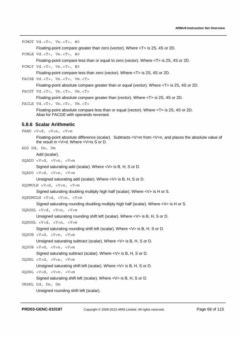
ARMv8 Instruction Set Overview
PRD03-GENC-010197 Copyright © 2009-2013 ARM Limited. All rights reserved. Page 69 of 115
FCMGT Vd.<T>, Vn.<T>, #0
Floating-point compare greater than zero (vector). Where <T> is 2S, 4S or 2D.
FCMLE Vd.<T>, Vn.<T>, #0
Floating-point compare less than or equal to zero (vector). Where <T> is 2S, 4S or 2D.
FCMLT Vd.<T>, Vn.<T>, #0
Floating-point compare less than zero (vector). Where <T> is 2S, 4S or 2D.
FACGE Vd.<T>, Vn.<T>, Vm.<T>
Floating-point absolute compare greater than or equal (vector). Where <T> is 2S, 4S or 2D.
FACGT Vd.<T>, Vn.<T>, Vm.<T>
Floating-point absolute compare greater than (vector). Where <T> is 2S, 4S or 2D.
FACLE Vd.<T>, Vn.<T>, Vm.<T>
Floating-point absolute compare less than or equal (vector). Where <T> is 2S, 4S or 2D. Alias for FACGE with operands reversed.
5.8.6 Scalar Arithmetic FABD <V>d, <V>n, <V>m
Floating-point absolute difference (scalar). Subtracts <V>m from <V>n, and places the absolute value of the result in <V>d. Where <V>is S or D.
ADD Dd, Dn, Dm
Add (scalar).
SQADD <V>d, <V>n, <V>m
Signed saturating add (scalar). Where <V> is B, H, S or D.
UQADD <V>d, <V>n, <V>m
Unsigned saturating add (scalar). Where <V> is B, H, S or D.
SQDMULH <V>d, <V>n, <V>m
Signed saturating doubling multiply high half (scalar). Where <V> is H or S.
SQRDMULH <V>d, <V>n, <V>m
Signed saturating rounding doubling multiply high half (scalar). Where <V> is H or S.
UQRSHL <V>d, <V>n, <V>m
Unsigned saturating rounding shift left (scalar). Where <V> is B, H, S or D.
SQRSHL <V>d, <V>n, <V>m
Signed saturating rounding shift left (scalar). Where <V> is B, H, S or D. UQSUB <V>d, <V>n, <V>m
Unsigned saturating subtract (scalar). Where <V> is B, H, S or D.
SQSUB <V>d, <V>n, <V>m
Signed saturating subtract (scalar). Where <V> is B, H, S or D.
UQSHL <V>d, <V>n, <V>m
Unsigned saturating shift left (scalar). Where <V> is B, H, S or D.
SQSHL <V>d, <V>n, <V>m
Signed saturating shift left (scalar). Where <V> is B, H, S or D.
URSHL Dd, Dn, Dm
Unsigned rounding shift left (scalar).
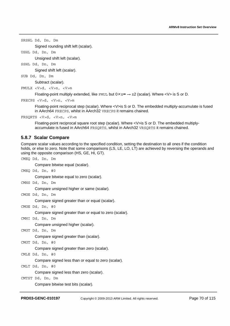
ARMv8 Instruction Set Overview
PRD03-GENC-010197 Copyright © 2009-2013 ARM Limited. All rights reserved. Page 70 of 115
SRSHL Dd, Dn, Dm
Signed rounding shift left (scalar).
USHL Dd, Dn, Dm
Unsigned shift left (scalar).
SSHL Dd, Dn, Dm
Signed shift left (scalar).
SUB Dd, Dn, Dm
Subtract (scalar).
FMULX <V>d, <V>n, <V>m
Floating-point multiply extended, like FMUL but 0�±∞ → ±2 (scalar). Where <V> is S or D.
FRECPS <V>d, <V>n, <V>m
Floating-point reciprocal step (scalar). Where <V>is S or D. The embedded multiply-accumulate is fused in AArch64 FRECPS, whilst in AArch32 VRECPS it remains chained.
FRSQRTS <V>d, <V>n, <V>m
Floating-point reciprocal square root step (scalar). Where <V>is S or D. The embedded multiply-accumulate is fused in AArch64 FRSQRTS, whilst in AArch32 VRSQRTS it remains chained.
5.8.7 Scalar Compare Compare scalar values according to the specified condition, setting the destination to all ones if the condition holds, or else to zero. Note that some comparisons (LS, LE, LO, LT) are achieved by reversing the operands and using the opposite comparison (HS, GE, HI, GT). CMEQ Dd, Dn, Dm
Compare bitwise equal (scalar).
CMEQ Dd, Dn, #0
Compare bitwise equal to zero (scalar).
CMHS Dd, Dn, Dm
Compare unsigned higher or same (scalar).
CMGE Dd, Dn, Dm
Compare signed greater than or equal (scalar).
CMGE Dd, Dn, #0
Compare signed greater than or equal to zero (scalar).
CMHI Dd, Dn, Dm
Compare unsigned higher (scalar). CMGT Dd, Dn, Dm
Compare signed greater than (scalar).
CMGT Dd, Dn, #0
Compare signed greater than zero (scalar).
CMLE Dd, Dn, #0
Compare signed less than or equal to zero (scalar).
CMLT Dd, Dn, #0
Compare signed less than zero (scalar).
CMTST Dd, Dn, Dm
Compare bitwise test bits (scalar).

ARMv8 Instruction Set Overview
PRD03-GENC-010197 Copyright © 2009-2013 ARM Limited. All rights reserved. Page 71 of 115
FCMEQ <V>d, <V>n, <V>m
Floating-point compare mask equal (scalar). Where <V>is S or D.
FCMEQ <V>d, <V>n, #0
Floating-point compare mask equal to zero (scalar). Where <V>is S or D.
FCMGE <V>d, <V>n, <V>m
Floating-point compare mask greater than or equal (scalar). Where <V>is S or D.
FCMGE <V>d, <V>n, #0
Floating-point compare mask greater than or equal to zero (scalar). Where <V>is S or D.
FCMGT <V>d, <V>n, <V>m
Floating-point compare mask greater than (scalar). Where <V>is S or D.
FCMGT <V>d, <V>n, #0
Floating-point compare mask greater than zero (scalar). Where <V>is S or D.
FCMLE <V>d, <V>n, #0
Floating-point compare mask less than or equal to zero (scalar). Where <V>is S or D.
FCMLT <V>d, <V>n, #0
Floating-point compare mask less than zero (scalar). Where <V>is S or D. FACGE <V>d, <V>n, <V>m
Floating-point absolute compare mask greater than or equal (scalar). Where <V>is S or D.
FACGT <V>d, <V>n, <V>m
Floating-point absolute compare mask greater than (scalar). Where <V>is S or D.
5.8.8 Vector Widening/Narrowing Arithmetic UABAL Vd.<Td>, Vn.<Ts>, Vm.<Ts>
Unsigned absolute difference and accumulate long (vector). Where the <Td>/<Ts> is 8H/8B, 4S/4H or 2D/2S.
UABAL2 Vd.<Td>, Vn.<Ts>, Vm.<Ts>
Unsigned absolute difference and accumulate long (vector, second part). Where the <Td>/<Ts> is 8H/16B, 4S/8H or 2D/4S.
SABAL Vd.<Td>, Vn.<Ts>, Vm.<Ts>
Signed absolute difference and accumulate long (vector). Where the <Td>/<Ts> is 8H/8B, 4S/4H or 2D/2S.
SABAL2 Vd.<Td>, Vn.<Ts>, Vm.<Ts>
Signed absolute difference and accumulate long (vector, second part). Where the <Td>/<Ts> is 8H/16B, 4S/8H or 2D/4S.
UABDL Vd.<Td>, Vn.<Ts>, Vm.<Ts>
Unsigned absolute difference long (vector). Where the <Td>/<Ts> is 8H/8B, 4S/4H or 2D/2S.
UABDL2 Vd.<Td>, Vn.<Ts>, Vm.<Ts>
Unsigned absolute difference long (vector, second part). Where the <Td>/<Ts> is 8H/16B, 4S/8H or 2D/4S.
SABDL Vd.<Td>, Vn.<Ts>, Vm.<Ts>
Signed absolute difference long (vector). Where the <Td>/<Ts> is 8H/8B, 4S/4H or 2D/2S.
SABDL2 Vd.<Td>, Vn.<Ts>, Vm.<Ts>
Signed absolute difference long (vector, second part). Where the <Td>/<Ts> is 8H/16B, 4S/8H or 2D/4S.
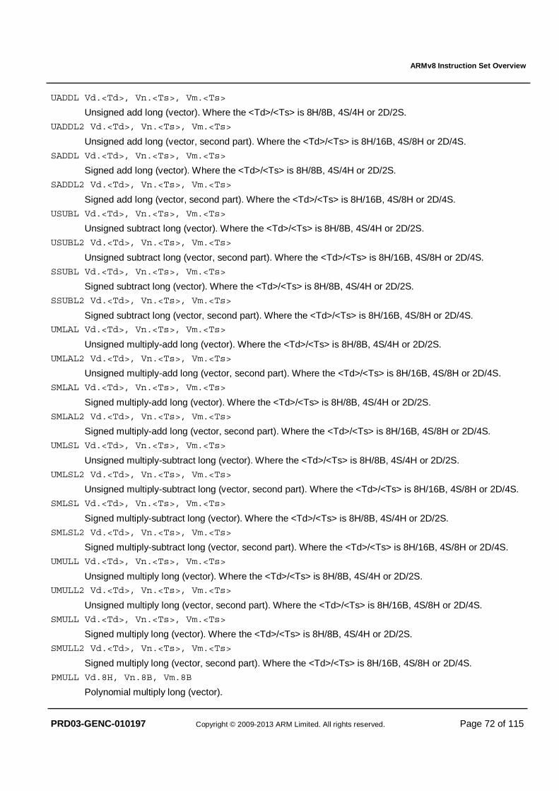
ARMv8 Instruction Set Overview
PRD03-GENC-010197 Copyright © 2009-2013 ARM Limited. All rights reserved. Page 72 of 115
UADDL Vd.<Td>, Vn.<Ts>, Vm.<Ts>
Unsigned add long (vector). Where the <Td>/<Ts> is 8H/8B, 4S/4H or 2D/2S.
UADDL2 Vd.<Td>, Vn.<Ts>, Vm.<Ts>
Unsigned add long (vector, second part). Where the <Td>/<Ts> is 8H/16B, 4S/8H or 2D/4S.
SADDL Vd.<Td>, Vn.<Ts>, Vm.<Ts>
Signed add long (vector). Where the <Td>/<Ts> is 8H/8B, 4S/4H or 2D/2S.
SADDL2 Vd.<Td>, Vn.<Ts>, Vm.<Ts>
Signed add long (vector, second part). Where the <Td>/<Ts> is 8H/16B, 4S/8H or 2D/4S.
USUBL Vd.<Td>, Vn.<Ts>, Vm.<Ts>
Unsigned subtract long (vector). Where the <Td>/<Ts> is 8H/8B, 4S/4H or 2D/2S.
USUBL2 Vd.<Td>, Vn.<Ts>, Vm.<Ts>
Unsigned subtract long (vector, second part). Where the <Td>/<Ts> is 8H/16B, 4S/8H or 2D/4S.
SSUBL Vd.<Td>, Vn.<Ts>, Vm.<Ts>
Signed subtract long (vector). Where the <Td>/<Ts> is 8H/8B, 4S/4H or 2D/2S.
SSUBL2 Vd.<Td>, Vn.<Ts>, Vm.<Ts>
Signed subtract long (vector, second part). Where the <Td>/<Ts> is 8H/16B, 4S/8H or 2D/4S. UMLAL Vd.<Td>, Vn.<Ts>, Vm.<Ts>
Unsigned multiply-add long (vector). Where the <Td>/<Ts> is 8H/8B, 4S/4H or 2D/2S.
UMLAL2 Vd.<Td>, Vn.<Ts>, Vm.<Ts>
Unsigned multiply-add long (vector, second part). Where the <Td>/<Ts> is 8H/16B, 4S/8H or 2D/4S.
SMLAL Vd.<Td>, Vn.<Ts>, Vm.<Ts>
Signed multiply-add long (vector). Where the <Td>/<Ts> is 8H/8B, 4S/4H or 2D/2S.
SMLAL2 Vd.<Td>, Vn.<Ts>, Vm.<Ts>
Signed multiply-add long (vector, second part). Where the <Td>/<Ts> is 8H/16B, 4S/8H or 2D/4S.
UMLSL Vd.<Td>, Vn.<Ts>, Vm.<Ts>
Unsigned multiply-subtract long (vector). Where the <Td>/<Ts> is 8H/8B, 4S/4H or 2D/2S.
UMLSL2 Vd.<Td>, Vn.<Ts>, Vm.<Ts>
Unsigned multiply-subtract long (vector, second part). Where the <Td>/<Ts> is 8H/16B, 4S/8H or 2D/4S.
SMLSL Vd.<Td>, Vn.<Ts>, Vm.<Ts>
Signed multiply-subtract long (vector). Where the <Td>/<Ts> is 8H/8B, 4S/4H or 2D/2S.
SMLSL2 Vd.<Td>, Vn.<Ts>, Vm.<Ts>
Signed multiply-subtract long (vector, second part). Where the <Td>/<Ts> is 8H/16B, 4S/8H or 2D/4S.
UMULL Vd.<Td>, Vn.<Ts>, Vm.<Ts>
Unsigned multiply long (vector). Where the <Td>/<Ts> is 8H/8B, 4S/4H or 2D/2S. UMULL2 Vd.<Td>, Vn.<Ts>, Vm.<Ts>
Unsigned multiply long (vector, second part). Where the <Td>/<Ts> is 8H/16B, 4S/8H or 2D/4S.
SMULL Vd.<Td>, Vn.<Ts>, Vm.<Ts>
Signed multiply long (vector). Where the <Td>/<Ts> is 8H/8B, 4S/4H or 2D/2S.
SMULL2 Vd.<Td>, Vn.<Ts>, Vm.<Ts>
Signed multiply long (vector, second part). Where the <Td>/<Ts> is 8H/16B, 4S/8H or 2D/4S.
PMULL Vd.8H, Vn.8B, Vm.8B
Polynomial multiply long (vector).
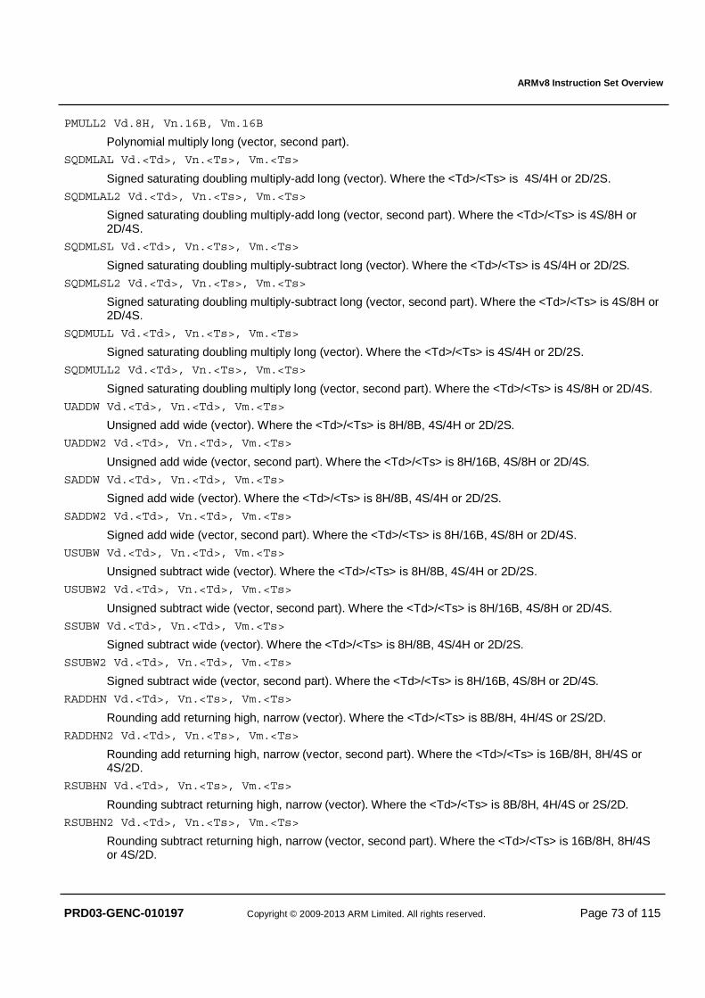
ARMv8 Instruction Set Overview
PRD03-GENC-010197 Copyright © 2009-2013 ARM Limited. All rights reserved. Page 73 of 115
PMULL2 Vd.8H, Vn.16B, Vm.16B
Polynomial multiply long (vector, second part).
SQDMLAL Vd.<Td>, Vn.<Ts>, Vm.<Ts>
Signed saturating doubling multiply-add long (vector). Where the <Td>/<Ts> is 4S/4H or 2D/2S.
SQDMLAL2 Vd.<Td>, Vn.<Ts>, Vm.<Ts>
Signed saturating doubling multiply-add long (vector, second part). Where the <Td>/<Ts> is 4S/8H or 2D/4S.
SQDMLSL Vd.<Td>, Vn.<Ts>, Vm.<Ts>
Signed saturating doubling multiply-subtract long (vector). Where the <Td>/<Ts> is 4S/4H or 2D/2S.
SQDMLSL2 Vd.<Td>, Vn.<Ts>, Vm.<Ts>
Signed saturating doubling multiply-subtract long (vector, second part). Where the <Td>/<Ts> is 4S/8H or 2D/4S.
SQDMULL Vd.<Td>, Vn.<Ts>, Vm.<Ts>
Signed saturating doubling multiply long (vector). Where the <Td>/<Ts> is 4S/4H or 2D/2S.
SQDMULL2 Vd.<Td>, Vn.<Ts>, Vm.<Ts>
Signed saturating doubling multiply long (vector, second part). Where the <Td>/<Ts> is 4S/8H or 2D/4S.
UADDW Vd.<Td>, Vn.<Td>, Vm.<Ts>
Unsigned add wide (vector). Where the <Td>/<Ts> is 8H/8B, 4S/4H or 2D/2S.
UADDW2 Vd.<Td>, Vn.<Td>, Vm.<Ts>
Unsigned add wide (vector, second part). Where the <Td>/<Ts> is 8H/16B, 4S/8H or 2D/4S.
SADDW Vd.<Td>, Vn.<Td>, Vm.<Ts>
Signed add wide (vector). Where the <Td>/<Ts> is 8H/8B, 4S/4H or 2D/2S.
SADDW2 Vd.<Td>, Vn.<Td>, Vm.<Ts>
Signed add wide (vector, second part). Where the <Td>/<Ts> is 8H/16B, 4S/8H or 2D/4S.
USUBW Vd.<Td>, Vn.<Td>, Vm.<Ts>
Unsigned subtract wide (vector). Where the <Td>/<Ts> is 8H/8B, 4S/4H or 2D/2S.
USUBW2 Vd.<Td>, Vn.<Td>, Vm.<Ts>
Unsigned subtract wide (vector, second part). Where the <Td>/<Ts> is 8H/16B, 4S/8H or 2D/4S.
SSUBW Vd.<Td>, Vn.<Td>, Vm.<Ts>
Signed subtract wide (vector). Where the <Td>/<Ts> is 8H/8B, 4S/4H or 2D/2S.
SSUBW2 Vd.<Td>, Vn.<Td>, Vm.<Ts>
Signed subtract wide (vector, second part). Where the <Td>/<Ts> is 8H/16B, 4S/8H or 2D/4S.
RADDHN Vd.<Td>, Vn.<Ts>, Vm.<Ts>
Rounding add returning high, narrow (vector). Where the <Td>/<Ts> is 8B/8H, 4H/4S or 2S/2D.
RADDHN2 Vd.<Td>, Vn.<Ts>, Vm.<Ts>
Rounding add returning high, narrow (vector, second part). Where the <Td>/<Ts> is 16B/8H, 8H/4S or 4S/2D.
RSUBHN Vd.<Td>, Vn.<Ts>, Vm.<Ts>
Rounding subtract returning high, narrow (vector). Where the <Td>/<Ts> is 8B/8H, 4H/4S or 2S/2D.
RSUBHN2 Vd.<Td>, Vn.<Ts>, Vm.<Ts>
Rounding subtract returning high, narrow (vector, second part). Where the <Td>/<Ts> is 16B/8H, 8H/4S or 4S/2D.
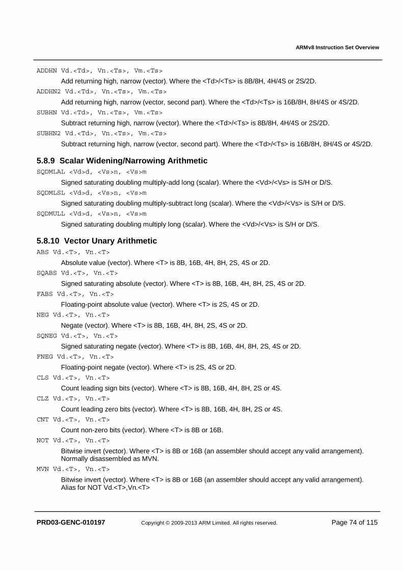
ARMv8 Instruction Set Overview
PRD03-GENC-010197 Copyright © 2009-2013 ARM Limited. All rights reserved. Page 74 of 115
ADDHN Vd.<Td>, Vn.<Ts>, Vm.<Ts>
Add returning high, narrow (vector). Where the <Td>/<Ts> is 8B/8H, 4H/4S or 2S/2D.
ADDHN2 Vd.<Td>, Vn.<Ts>, Vm.<Ts>
Add returning high, narrow (vector, second part). Where the <Td>/<Ts> is 16B/8H, 8H/4S or 4S/2D.
SUBHN Vd.<Td>, Vn.<Ts>, Vm.<Ts>
Subtract returning high, narrow (vector). Where the <Td>/<Ts> is 8B/8H, 4H/4S or 2S/2D.
SUBHN2 Vd.<Td>, Vn.<Ts>, Vm.<Ts>
Subtract returning high, narrow (vector, second part). Where the <Td>/<Ts> is 16B/8H, 8H/4S or 4S/2D.
5.8.9 Scalar Widening/Narrowing Arithmetic SQDMLAL <Vd>d, <Vs>n, <Vs>m
Signed saturating doubling multiply-add long (scalar). Where the <Vd>/<Vs> is S/H or D/S.
SQDMLSL <Vd>d, <Vs>n, <Vs>m
Signed saturating doubling multiply-subtract long (scalar). Where the <Vd>/<Vs> is S/H or D/S.
SQDMULL <Vd>d, <Vs>n, <Vs>m
Signed saturating doubling multiply long (scalar). Where the <Vd>/<Vs> is S/H or D/S.
5.8.10 Vector Unary Arithmetic ABS Vd.<T>, Vn.<T>
Absolute value (vector). Where <T> is 8B, 16B, 4H, 8H, 2S, 4S or 2D. SQABS Vd.<T>, Vn.<T>
Signed saturating absolute (vector). Where <T> is 8B, 16B, 4H, 8H, 2S, 4S or 2D.
FABS Vd.<T>, Vn.<T>
Floating-point absolute value (vector). Where <T> is 2S, 4S or 2D.
NEG Vd.<T>, Vn.<T>
Negate (vector). Where <T> is 8B, 16B, 4H, 8H, 2S, 4S or 2D.
SQNEG Vd.<T>, Vn.<T>
Signed saturating negate (vector). Where <T> is 8B, 16B, 4H, 8H, 2S, 4S or 2D.
FNEG Vd.<T>, Vn.<T>
Floating-point negate (vector). Where <T> is 2S, 4S or 2D.
CLS Vd.<T>, Vn.<T>
Count leading sign bits (vector). Where <T> is 8B, 16B, 4H, 8H, 2S or 4S.
CLZ Vd.<T>, Vn.<T>
Count leading zero bits (vector). Where <T> is 8B, 16B, 4H, 8H, 2S or 4S.
CNT Vd.<T>, Vn.<T>
Count non-zero bits (vector). Where <T> is 8B or 16B.
NOT Vd.<T>, Vn.<T>
Bitwise invert (vector). Where <T> is 8B or 16B (an assembler should accept any valid arrangement). Normally disassembled as MVN.
MVN Vd.<T>, Vn.<T>
Bitwise invert (vector). Where <T> is 8B or 16B (an assembler should accept any valid arrangement). Alias for NOT Vd.<T>,Vn.<T>
ARMv8 Instruction Set Overview
PRD03-GENC-010197 Copyright © 2009-2013 ARM Limited. All rights reserved. Page 75 of 115
SUQADD Vd.<T>, Vn.<T>
Signed saturating accumulate of unsigned value (vector). Where <T> is 8B, 16B, 4H, 8H, 2S, 4S or 2D.
USQADD Vd.<T>, Vn.<T>
Unsigned saturating accumulate of signed value (vector). Where <T> is 8B, 16B, 4H, 8H, 2S, 4S or 2D.
UADALP Vd.<Td>, Vn.<Ts>
Unsigned add and accumulate long pairwise (vector). Where <Td>/<Ts> is 4H/8B, 8H/16B, 2S/4H, 4S/8H, 1D/2S or 2D/4S.
SADALP Vd.<Td>, Vn.<Ts>
Signed add and accumulate long pairwise (vector). Where <Td>/<Ts> is 4H/8B, 8H/16B, 2S/4H, 4S/8H, 1D/2S or 2D/4S.
UADDLP Vd.<Td>, Vn.<Ts>
Unsigned add long pair (vector). Where <Td>/<Ts> is 4H/8B, 8H/16B, 2S/4H, 4S/8H, 1D/2S or 2D/4S.
SADDLP Vd.<Td>, Vn.<Ts>
Signed add long pair (vector). Where <Td>/<Ts> is 4H/8B, 8H/16B, 2S/4H, 4S/8H, 1D/2S or 2D/4S.
FCVTL Vd.<Td>, Vn.<Ts>
Floating-point convert precision long, convertinghalf-precision to single-precision, or single-precision to double-precision (vector). Where <Td>/<Ts> is 4S/4H or 2D/2S
FCVTL2 Vd.<Td>, Vn.<Ts>
Floating-point convert precision long, converting half-precision to single-precision, or single-precision to double-precision (vector, second part). Where <Td>/<Ts> is 4S/8H or 2D/4S
XTN Vd.<Td>, Vn.<Ts>
Extract narrow (vector). Where <Td>/<Ts> is 8B/8H, 4H/4S, or 2S/2D.
XTN2 Vd.<Td>, Vn.<Ts>
Extract narrow (vector, second part). Where <Td>/<Ts> is 16B/8H, 8H/4S, or 4S/2D.
SQXTUN Vd.<Td>, Vn.<Ts>
Signed saturating extract unsigned narrow (vector). Where <Td>/<Ts> is 8B/8H, 4H/4S, or 2S/2D. SQXTUN2 Vd.<Td>, Vn.<Ts>
Signed saturating extract unsigned narrow (vector, second part). Where <Td>/<Ts> is 16B/8H, 8H/4S, or 4S/2D.
UQXTN Vd.<Td>, Vn.<Ts>
Unsigned saturating extract narrow (vector). Where <Td>/<Ts> is 8B/8H, 4H/4S, or 2S/2D.
UQXTN2 Vd.<Td>, Vn.<Ts>
Unsigned saturating extract narrow (vector, second part). Where <Td>/<Ts> is 16B/8H, 8H/4S, or 4S/2D.
SQXTN Vd.<Td>, Vn.<Ts>
Signed saturating extract narrow (vector). Where <Td>/<Ts> is 8B/8H, 4H/4S, or 2S/2D.
SQXTN2 Vd.<Td>, Vn.<Ts>
Signed saturating extract narrow (vector, second part). Where <Td>/<Ts> is 16B/8H, 8H/4S, or 4S/2D.
FCVTN Vd.<Td>, Vn.<Ts>
Floating-point convert precision narrow, convertingsingle-precision to half-precision, or double-precision to single-precision using FPCR rounding mode (vector). Where <Td>/<Ts> is 4H/4S or 2S/2D.
FCVTN2 Vd.<Td>, Vn.<Ts>
Floating-point convert precision narrow, converting single-precision to half-precision, or double-precision to single-precision using FPCR rounding mode (vector, second part). Where <Td>/<Ts> is 8H/4S or 4S/2D.
ARMv8 Instruction Set Overview
PRD03-GENC-010197 Copyright © 2009-2013 ARM Limited. All rights reserved. Page 76 of 115
FCVTXN Vd.2S, Vn.2D
Floating-point convert precision narrow, converting double-precision to single-precision with inexact result rounding to odd (vector). Rounding to odd, or Von Neumann's rounding, is only suitable for further narrowing to half-precision giving correct rounding of the half-precision result.
FCVTXN2 Vd.4S, Vn.2D
Floating-point convert precision narrow, converting double-precision to single-precision with inexact result rounding to odd (vector, second part). Rounding to odd, or Von Neumann's rounding, is only suitable for further narrowing to half-precision giving correct rounding of the half-precision result.
FRINT<r> Vd.<T>, Vn.<T>
Floating-point round to integral floating-point value (vector). Where <T> is 2S, 4S or 2D. The syntax term <r> selects the rounding mode: N (nearest with ties to even); A (nearest with ties to away), P (towards +Inf); M (towards –Inf), Z (towards zero), I (using FPCR rounding mode) and X (using FPCR rounding mode, with exactness test).
FSQRT Vd.<T>, Vn.<T>
Floating-point square root (vector). Where <T> is 2S, 4S or 2D.
URECPE Vd.<T>, Vn.<T>
Unsigned reciprocal estimate (vector). Where <T> is 2S or 4S. FRECPE Vd.<T>, Vn.<T>
Floating-point reciprocal estimate (vector). Where <T> is 2S, 4S or 2D.
URSQRTE Vd.<T>, Vn.<T>
Unsigned reciprocal square root estimate (vector). Where <T> is 2S or 4S.
FRSQRTE Vd.<T>, Vn.<T>
Floating-point reciprocal square root estimate (vector). Where <T> is 2S, 4S or 2D.
RBIT Vd.<T>, Vn.<T>
Reverse bits (vector): reverses the bits within each byte vector element. Where <T> is 8B or 16B.
REV16 Vd.<T>, Vn.<T>
Reverse elements in 16-bit halfwords (vector). Where <T> is 8B or 16B.
REV32 Vd.<T>, Vn.<T>
Reverse elements in 32-bit words (vector). Where <T> is 8B, 16B, 4H, or 8H.
REV64 Vd.<T>, Vn.<T>
Reverse elements in 64-bit doublewords (vector). Where <T> is 8B, 16B, 4H, 8H, 2S or 4S.
5.8.11 Scalar Unary Arithmetic ABS Dd, Dn
Absolute value (scalar).
SQABS <V>d, <V>n
Signed saturating absolute value (scalar). Where <V> is B, H, S or D.
NEG Dd, Dn
Negate (scalar). SQNEG <V>d, <V>n
Signed saturating negate (scalar). Where <V> is B, H, S or D.
SUQADD <V>d, <V>n
Signed saturating accumulate of unsigned value (scalar). Where <V> is B, H, S or D.
ARMv8 Instruction Set Overview
PRD03-GENC-010197 Copyright © 2009-2013 ARM Limited. All rights reserved. Page 77 of 115
USQADD <V>d, <V>n
Unsigned saturating accumulate of signed value Where <V> is B, H, S or D.
SQXTUN <Vd>d, <Vs>n
Signed saturating extract unsigned narrow (scalar). Where <Vd>/<Vs> is B/H, H/S or S/D.
UQXTN <Vd>d, <Vs>n
Unsigned saturating extract narrow (scalar). Where <Vd>/<Vs> is B/H, H/S or S/D.
SQXTN <Vd>d, <Vs>n
Signed saturating extract narrow (scalar). Where <Vd>/<Vs> is B/H, H/S or S/D.
FCVTXN Sd, Dn
Floating-point convert precision narrow, converting double-precision to single-precision with inexact result rounding to odd (scalar). Rounding to odd, or Von Neumann's rounding, is only suitable for further narrowing to half-precision giving correct rounding of the half-precision result.
FRECPE <V>d, <V>n
Floating-point reciprocal estimate (scalar). Where <V> is S or D.
FRECPX <V>d, <V>n
Floating-point reciprocal exponent (scalar). Where <V> is S or D.
FRSQRTE <V>d, <V>n
Floating-point reciprocal square root estimate (scalar). Where <V> is S or D.
5.8.12 Vector-by-element Arithmetic In all cases the immediate index is a constant in the range 0 to (16/sizeof(<Ts>))–1.
FMLA Vd.<T>, Vn.<T>, Vm.<Ts>[index]
Floating-point fused multiply-add (vector, by element). Where <T>/<Ts> is 2S/S, 4S/S or 2D/D. FMLS Vd.<T>, Vn.<T>, Vm.<Ts>[index]
Floating-point fused multiply-subtract (vector, by element). Where <T>/<Ts> is 2S/S, 4S/S or 2D/D.
FMUL Vd.<T>, Vn.<T>, Vm.<Ts>[index]
Floating-point multiply (vector, by element). Where <Td>/<Ts> is 2S/S 4S/S or 2D/D.
FMULX Vd.<T>, Vn.<T>, Vm.<Ts>[index]
Floating-point multiply extended (vector, by element): like FMUL but 0�±∞ → ±2. Where <Td>/<Ts> is 2S/S, 4S/S or 2D/D.
MLA Vd.<T>, Vn.<T>, Vm.<Ts>[index]
Multiply-add (vector, by element). Where <T>/<Ts> is 4H/H, 8H/H, 2S/S or 4S/S. If <Ts> is H, then Vm must be in the range V0-V15.
MLS Vd.<T>, Vn.<T>, Vm.<Ts>[index]
Multiply-subtract (vector, by element). Where <T>/<Ts> is 4H/H, 8H/H, 2S/S or 4S/S. If <Ts> is H, then Vm must be in the range V0-V15.
MUL Vd.<T>, Vn.<T>, Vm.<Ts>[index]
Multiply (vector, by element). Where <T>/<Ts> is 4H/H, 8H/H, 2S/S or 4S/S. If <Ts> is H, then Vm must be in the range V0-V15.
SMLAL Vd.<Ta>, Vn.<Tb>, Vm.<Ts>[index]
Signed multiply-add long (vector, by element). Where <Ta>/<Tb>/<Ts> is 4S/4H/H or 2D/2S/S. If <Ts> is H, then Vm must be in the range V0-V15.
ARMv8 Instruction Set Overview
PRD03-GENC-010197 Copyright © 2009-2013 ARM Limited. All rights reserved. Page 78 of 115
SMLAL2 Vd.<Ta>, Vn.<Tb>, Vm.<Ts>[index]
Signed multiply-add long (vector, by element, second part). Where <Ta>/<Tb>/<Ts> is 4S/8H/H or 2D/4S/S. If <Ts> is H, then Vm must be in the range V0-V15.
SMLSL Vd.<Ta>, Vn.<Tb>, Vm.<Ts>[index]
Signed multiply-subtract long (vector, by element). Where <Ta>/<Tb>/<Ts> is 4S/4H/H or 2D/2S/S. If <Ts> is H, then Vm must be in the range V0-V15.
SMLSL2 Vd.<Ta>, Vn.<Tb>, Vm.<Ts>[index]
Signed multiply-subtract long (vector, by element, second part). Where <Ta>/<Tb>/<Ts> is 4S/8H/H or 2D/4S/S. If <Ts> is H, then Vm must be in the range V0-V15. If <Ts> is H, then Vm must be in the range V0-V15.
SMULL Vd.<Ta>, Vn.<Tb>, Vm.<Ts>[index]
Signed multiply long (vector, by element). Where <Ta>/<Tb>/<Ts> is 4S/4H/H or 2D/2S/S. If <Ts> is H, then Vm must be in the range V0-V15.
SMULL2 Vd.<Ta>, Vn.<Tb>, Vm.<Ts>[index]
Signed multiply long (vector, by element, second part). Where <Ta>/<Tb>/<Ts> is 4S/8H/H or 2D/4S/S. If <Ts> is H, then Vm must be in the range V0-V15.
UMLAL Vd.<Ta>, Vn.<Tb>, Vm.<Ts>[index]
Unsigned multiply-add long (vector, by element). Where <Ta>/<Tb>/<Ts> is 4S/4H/H or 2D/2S/S. If <Ts> is H, then Vm must be in the range V0-V15.
UMLAL2 Vd.<Ta>, Vn.<Tb>, Vm.<Ts>[index]
Unsigned multiply-add long (vector, by element, second part). Where <Ta>/<Tb>/<Ts> is 4S/8H/H or 2D/4S/S. If <Ts> is H, then Vm must be in the range V0-V15.
UMLSL Vd.<Ta>, Vn.<Tb>, Vm.<Ts>[index]
Unsigned multiply-subtract long (vector, by element). Where <Ta>/<Tb>/<Ts> is 4S/4H/H or 2D/2S/S. If <Ts> is H, then Vm must be in the range V0-V15.
UMLSL2 Vd.<Ta>, Vn.<Tb>, Vm.<Ts>[index]
Unsigned multiply-subtract long (vector, by element, second part). Where <Ta>/<Tb>/<Ts> is 4S/8H/H or 2D/4S/S. If <Ts> is H, then Vm must be in the range V0-V15.
UMULL Vd.<Ta>, Vn.<Tb>, Vm.<Ts>[index]
Unsigned multiply long (vector, by element). Where <Ta>/<Tb>/<Ts> is 4S/4H/H or 2D/2S/S. If <Ts> is H, then Vm must be in the range V0-V15.
UMULL2 Vd.<Ta>, Vn.<Tb>, Vm.<Ts>[index]
Unsigned multiply long (vector, by element, second part). Where <Ta>/<Tb>/<Ts> is 4S/8H/H or 2D/4S/S. If <Ts> is H, then Vm must be in the range V0-V15.
SQDMLAL Vd.<Ta>, Vn.<Tb>, Vm.<Ts>[index]
Signed saturating doubling multiply-add long (vector, by element). Where <Ta>/<Tb>/<Ts> is 4S/4H/H or 2D/2S/S. If <Ts> is H, then Vm must be in the range V0-V15.
SQDMLAL2 Vd.<Ta>, Vn.<Tb>, Vm.<Ts>[index]
Signed saturating doubling multiply-add long (vector, by element, second part). Where <Ta>/<Tb>/<Ts> is 4S/8H/H or 2D/4S/S. If <Ts> is H, then Vm must be in the range V0-V15.
SQDMLSL Vd.<Ta>, Vn.<Tb>, Vm.<Ts>[index]
Signed saturating doubling multiply-subtract long (vector, by element). Where <Ta>/<Tb>/<Ts> is 4S/4H/H or 2D/2S/S. If <Ts> is H, then Vm must be in the range V0-V15.
SQDMLSL2 Vd.<Ta>, Vn.<Tb>, Vm.<Ts>[index]
Signed saturating doubling multiply-subtract long (vector, by element, second part). Where <Ta>/<Tb>/<Ts> is 4S/8H/H or 2D/4S/S. If <Ts> is H, then Vm must be in the range V0-V15.
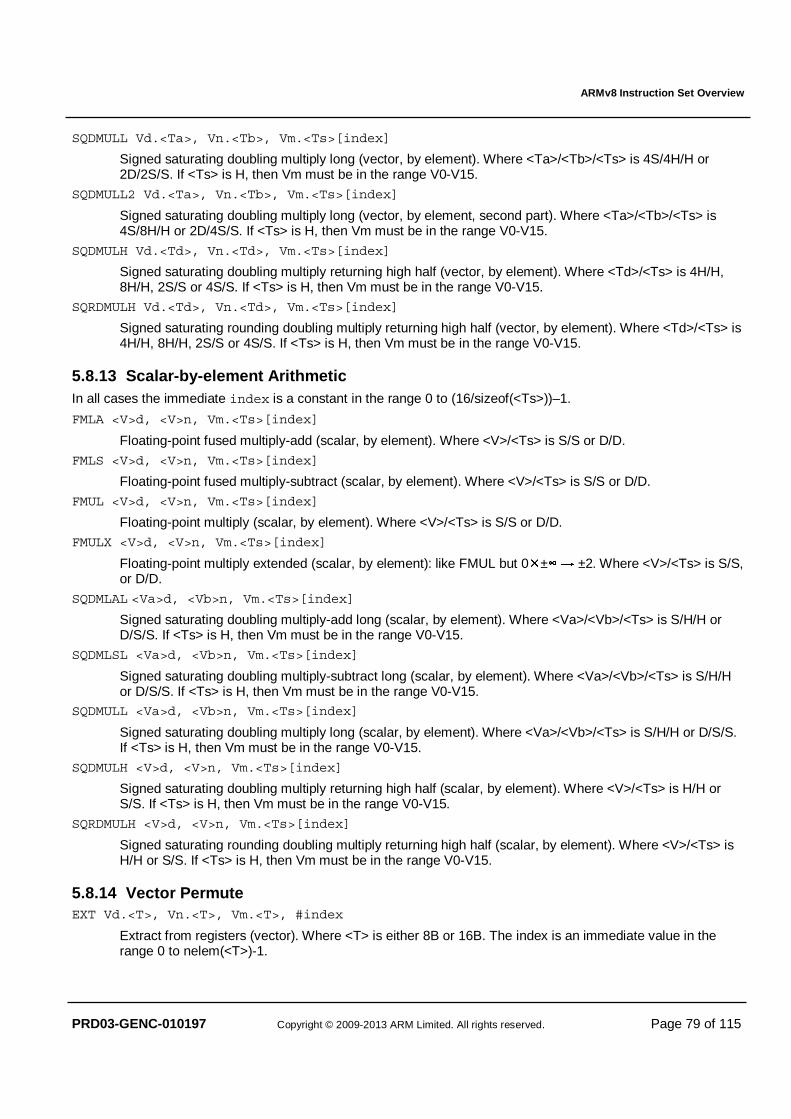
ARMv8 Instruction Set Overview
PRD03-GENC-010197 Copyright © 2009-2013 ARM Limited. All rights reserved. Page 79 of 115
SQDMULL Vd.<Ta>, Vn.<Tb>, Vm.<Ts>[index]
Signed saturating doubling multiply long (vector, by element). Where <Ta>/<Tb>/<Ts> is 4S/4H/H or 2D/2S/S. If <Ts> is H, then Vm must be in the range V0-V15.
SQDMULL2 Vd.<Ta>, Vn.<Tb>, Vm.<Ts>[index]
Signed saturating doubling multiply long (vector, by element, second part). Where <Ta>/<Tb>/<Ts> is 4S/8H/H or 2D/4S/S. If <Ts> is H, then Vm must be in the range V0-V15.
SQDMULH Vd.<Td>, Vn.<Td>, Vm.<Ts>[index]
Signed saturating doubling multiply returning high half (vector, by element). Where <Td>/<Ts> is 4H/H, 8H/H, 2S/S or 4S/S. If <Ts> is H, then Vm must be in the range V0-V15.
SQRDMULH Vd.<Td>, Vn.<Td>, Vm.<Ts>[index]
Signed saturating rounding doubling multiply returning high half (vector, by element). Where <Td>/<Ts> is 4H/H, 8H/H, 2S/S or 4S/S. If <Ts> is H, then Vm must be in the range V0-V15.
5.8.13 Scalar-by-element Arithmetic In all cases the immediate index is a constant in the range 0 to (16/sizeof(<Ts>))–1.
FMLA <V>d, <V>n, Vm.<Ts>[index]
Floating-point fused multiply-add (scalar, by element). Where <V>/<Ts> is S/S or D/D.
FMLS <V>d, <V>n, Vm.<Ts>[index]
Floating-point fused multiply-subtract (scalar, by element). Where <V>/<Ts> is S/S or D/D.
FMUL <V>d, <V>n, Vm.<Ts>[index]
Floating-point multiply (scalar, by element). Where <V>/<Ts> is S/S or D/D.
FMULX <V>d, <V>n, Vm.<Ts>[index]
Floating-point multiply extended (scalar, by element): like FMUL but 0�±∞ → ±2. Where <V>/<Ts> is S/S, or D/D.
SQDMLAL <Va>d, <Vb>n, Vm.<Ts>[index]
Signed saturating doubling multiply-add long (scalar, by element). Where <Va>/<Vb>/<Ts> is S/H/H or D/S/S. If <Ts> is H, then Vm must be in the range V0-V15.
SQDMLSL <Va>d, <Vb>n, Vm.<Ts>[index]
Signed saturating doubling multiply-subtract long (scalar, by element). Where <Va>/<Vb>/<Ts> is S/H/H or D/S/S. If <Ts> is H, then Vm must be in the range V0-V15.
SQDMULL <Va>d, <Vb>n, Vm.<Ts>[index]
Signed saturating doubling multiply long (scalar, by element). Where <Va>/<Vb>/<Ts> is S/H/H or D/S/S. If <Ts> is H, then Vm must be in the range V0-V15.
SQDMULH <V>d, <V>n, Vm.<Ts>[index]
Signed saturating doubling multiply returning high half (scalar, by element). Where <V>/<Ts> is H/H or S/S. If <Ts> is H, then Vm must be in the range V0-V15.
SQRDMULH <V>d, <V>n, Vm.<Ts>[index]
Signed saturating rounding doubling multiply returning high half (scalar, by element). Where <V>/<Ts> is H/H or S/S. If <Ts> is H, then Vm must be in the range V0-V15.
5.8.14 Vector Permute EXT Vd.<T>, Vn.<T>, Vm.<T>, #index
Extract from registers (vector). Where <T> is either 8B or 16B. The index is an immediate value in the range 0 to nelem(<T>)-1.
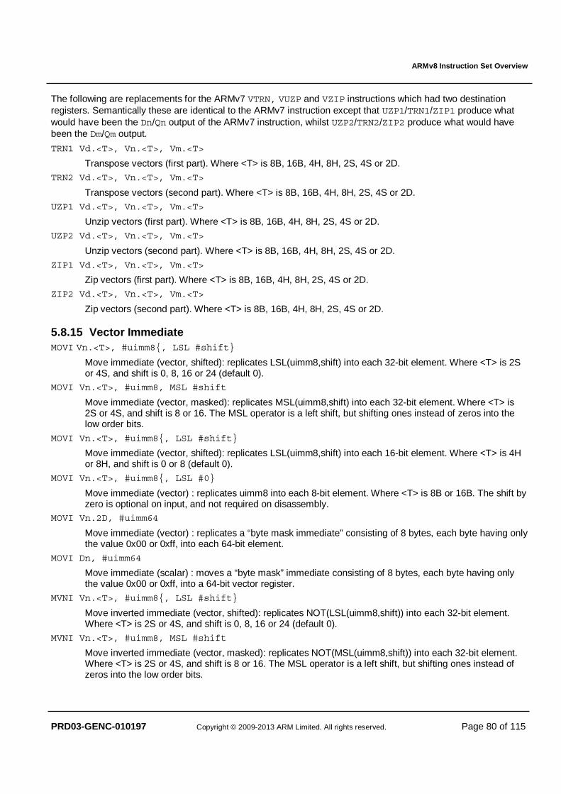
ARMv8 Instruction Set Overview
PRD03-GENC-010197 Copyright © 2009-2013 ARM Limited. All rights reserved. Page 80 of 115
The following are replacements for the ARMv7 VTRN, VUZP and VZIP instructions which had two destination registers. Semantically these are identical to the ARMv7 instruction except that UZP1/TRN1/ZIP1 produce what would have been the Dn/Qn output of the ARMv7 instruction, whilst UZP2/TRN2/ZIP2 produce what would have been the Dm/Qm output.
TRN1 Vd.<T>, Vn.<T>, Vm.<T>
Transpose vectors (first part). Where <T> is 8B, 16B, 4H, 8H, 2S, 4S or 2D.
TRN2 Vd.<T>, Vn.<T>, Vm.<T>
Transpose vectors (second part). Where <T> is 8B, 16B, 4H, 8H, 2S, 4S or 2D.
UZP1 Vd.<T>, Vn.<T>, Vm.<T>
Unzip vectors (first part). Where <T> is 8B, 16B, 4H, 8H, 2S, 4S or 2D.
UZP2 Vd.<T>, Vn.<T>, Vm.<T>
Unzip vectors (second part). Where <T> is 8B, 16B, 4H, 8H, 2S, 4S or 2D.
ZIP1 Vd.<T>, Vn.<T>, Vm.<T>
Zip vectors (first part). Where <T> is 8B, 16B, 4H, 8H, 2S, 4S or 2D.
ZIP2 Vd.<T>, Vn.<T>, Vm.<T>
Zip vectors (second part). Where <T> is 8B, 16B, 4H, 8H, 2S, 4S or 2D.
5.8.15 Vector Immediate MOVI Vn.<T>, #uimm8{, LSL #shift}
Move immediate (vector, shifted): replicates LSL(uimm8,shift) into each 32-bit element. Where <T> is 2S or 4S, and shift is 0, 8, 16 or 24 (default 0).
MOVI Vn.<T>, #uimm8, MSL #shift
Move immediate (vector, masked): replicates MSL(uimm8,shift) into each 32-bit element. Where <T> is 2S or 4S, and shift is 8 or 16. The MSL operator is a left shift, but shifting ones instead of zeros into the low order bits.
MOVI Vn.<T>, #uimm8{, LSL #shift}
Move immediate (vector, shifted): replicates LSL(uimm8,shift) into each 16-bit element. Where <T> is 4H or 8H, and shift is 0 or 8 (default 0).
MOVI Vn.<T>, #uimm8{, LSL #0}
Move immediate (vector) : replicates uimm8 into each 8-bit element. Where <T> is 8B or 16B. The shift by zero is optional on input, and not required on disassembly.
MOVI Vn.2D, #uimm64
Move immediate (vector) : replicates a “byte mask immediate” consisting of 8 bytes, each byte having only the value 0x00 or 0xff, into each 64-bit element.
MOVI Dn, #uimm64
Move immediate (scalar) : moves a “byte mask” immediate consisting of 8 bytes, each byte having only the value 0x00 or 0xff, into a 64-bit vector register.
MVNI Vn.<T>, #uimm8{, LSL #shift}
Move inverted immediate (vector, shifted): replicates NOT(LSL(uimm8,shift)) into each 32-bit element. Where <T> is 2S or 4S, and shift is 0, 8, 16 or 24 (default 0).
MVNI Vn.<T>, #uimm8, MSL #shift
Move inverted immediate (vector, masked): replicates NOT(MSL(uimm8,shift)) into each 32-bit element. Where <T> is 2S or 4S, and shift is 8 or 16. The MSL operator is a left shift, but shifting ones instead of zeros into the low order bits.
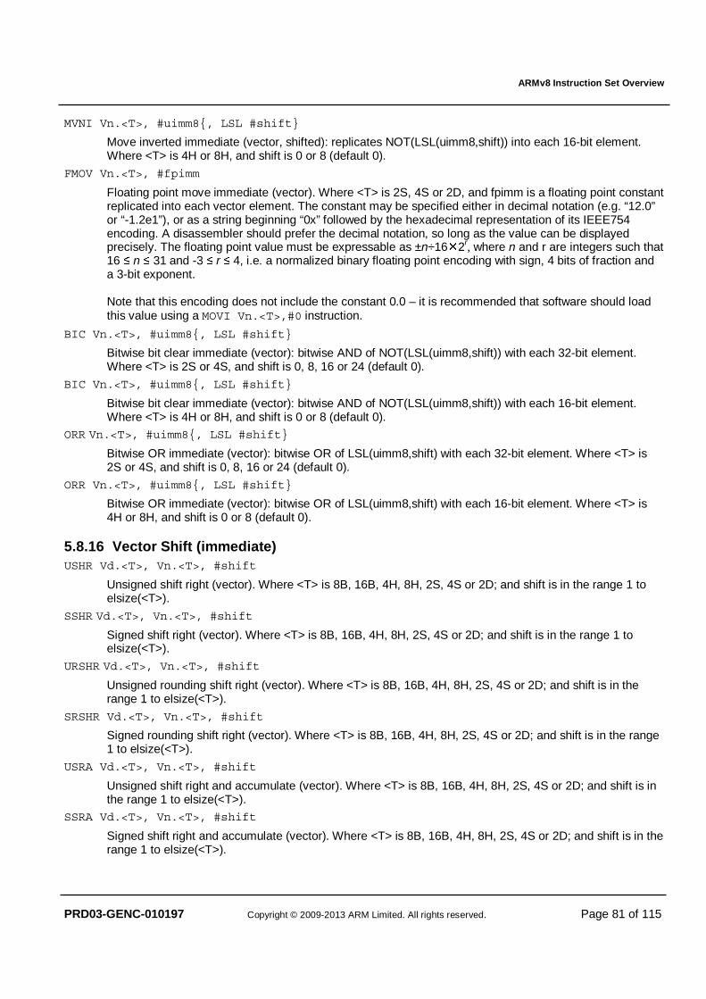
ARMv8 Instruction Set Overview
PRD03-GENC-010197 Copyright © 2009-2013 ARM Limited. All rights reserved. Page 81 of 115
MVNI Vn.<T>, #uimm8{, LSL #shift}
Move inverted immediate (vector, shifted): replicates NOT(LSL(uimm8,shift)) into each 16-bit element. Where <T> is 4H or 8H, and shift is 0 or 8 (default 0).
FMOV Vn.<T>, #fpimm
Floating point move immediate (vector). Where <T> is 2S, 4S or 2D, and fpimm is a floating point constant replicated into each vector element. The constant may be specified either in decimal notation (e.g. “12.0” or “-1.2e1”), or as a string beginning “0x” followed by the hexadecimal representation of its IEEE754 encoding. A disassembler should prefer the decimal notation, so long as the value can be displayed precisely. The floating point value must be expressable as ±n÷16�2r, where n and r are integers such that 16 ≤ n ≤ 31 and -3 ≤ r ≤ 4, i.e. a normalized binary floating point encoding with sign, 4 bits of fraction and a 3-bit exponent. Note that this encoding does not include the constant 0.0 – it is recommended that software should load this value using a MOVI Vn.<T>,#0 instruction.
BIC Vn.<T>, #uimm8{, LSL #shift}
Bitwise bit clear immediate (vector): bitwise AND of NOT(LSL(uimm8,shift)) with each 32-bit element. Where <T> is 2S or 4S, and shift is 0, 8, 16 or 24 (default 0).
BIC Vn.<T>, #uimm8{, LSL #shift}
Bitwise bit clear immediate (vector): bitwise AND of NOT(LSL(uimm8,shift)) with each 16-bit element. Where <T> is 4H or 8H, and shift is 0 or 8 (default 0).
ORR Vn.<T>, #uimm8{, LSL #shift}
Bitwise OR immediate (vector): bitwise OR of LSL(uimm8,shift) with each 32-bit element. Where <T> is 2S or 4S, and shift is 0, 8, 16 or 24 (default 0).
ORR Vn.<T>, #uimm8{, LSL #shift}
Bitwise OR immediate (vector): bitwise OR of LSL(uimm8,shift) with each 16-bit element. Where <T> is 4H or 8H, and shift is 0 or 8 (default 0).
5.8.16 Vector Shift (immediate) USHR Vd.<T>, Vn.<T>, #shift
Unsigned shift right (vector). Where <T> is 8B, 16B, 4H, 8H, 2S, 4S or 2D; and shift is in the range 1 to elsize(<T>).
SSHR Vd.<T>, Vn.<T>, #shift
Signed shift right (vector). Where <T> is 8B, 16B, 4H, 8H, 2S, 4S or 2D; and shift is in the range 1 to elsize(<T>).
URSHR Vd.<T>, Vn.<T>, #shift
Unsigned rounding shift right (vector). Where <T> is 8B, 16B, 4H, 8H, 2S, 4S or 2D; and shift is in the range 1 to elsize(<T>).
SRSHR Vd.<T>, Vn.<T>, #shift
Signed rounding shift right (vector). Where <T> is 8B, 16B, 4H, 8H, 2S, 4S or 2D; and shift is in the range 1 to elsize(<T>).
USRA Vd.<T>, Vn.<T>, #shift
Unsigned shift right and accumulate (vector). Where <T> is 8B, 16B, 4H, 8H, 2S, 4S or 2D; and shift is in the range 1 to elsize(<T>).
SSRA Vd.<T>, Vn.<T>, #shift
Signed shift right and accumulate (vector). Where <T> is 8B, 16B, 4H, 8H, 2S, 4S or 2D; and shift is in the range 1 to elsize(<T>).

ARMv8 Instruction Set Overview
PRD03-GENC-010197 Copyright © 2009-2013 ARM Limited. All rights reserved. Page 82 of 115
URSRA Vd.<T>, Vn.<T>, #shift
Unsigned rounding shift right and accumulate (vector). Where <T> is 8B, 16B, 4H, 8H, 2S, 4S or 2D; and shift is in the range 1 to elsize(<T>).
SRSRA Vd.<T>, Vn.<T>, #shift
Signed rounding shift right and accumulate (vector). Where <T> is 8B, 16B, 4H, 8H, 2S, 4S or 2D; and shift is in the range 1 to elsize(<T>).
SRI Vd.<T>, Vn.<T>, #shift
Shift right and insert (vector). Where <T> is 8B, 16B, 4H, 8H, 2S, 4S or 2D; and shift is in the range 1 to elsize(<T>).
SHRN Vd.<Td>, Vn.<Ts>, #shift
Shift right narrow (vector). Where <Td>/<Ts> is 8B/8H, 4H/4S, or 2S/2D; and shift is in the range 1 to elsize(<Td>).
SHRN2 Vd.<Td>, Vn.<Ts>, #shift
Shift right narrow (vector, second part). Where <Td>/<Ts> is 16B/8H, 8H/4S, or 4S/2D; and shift is in the range 1 to elsize(<Td>).
UQSHRN Vd.<Td>, Vn.<Ts>, #shift
Unsigned saturating shift right narrow (vector). Where <Td>/<Ts> is 8B/8H, 4H/4S, or 2S/2D; and shift is in the range 1 to elsize(<Td>).
UQSHRN2 Vd.<Td>, Vn.<Ts>, #shift
Unsigned saturating shift right narrow (vector, second part). Where <Td>/<Ts> is 16B/8H, 8H/4S, or 4S/2D; and shift is in the range 1 to elsize(<Td>).
SQSHRN Vd.<Td>, Vn.<Ts>, #shift
Signed saturating shift right narrow (vector). Where <Td>/<Ts> is 8B/8H, 4H/4S, or 2S/2D; and shift is in the range 1 to elsize(<Td>).
SQSHRN2 Vd.<Td>, Vn.<Ts>, #shift
Signed saturating shift right narrow (vector, second part). Where <Td>/<Ts> is 16B/8H, 8H/4S, or 4S/2D; and shift is in the range 1 to elsize(<Td>).
RSHRN Vd.<Td>, Vn.<Ts>, #shift
Rounding shift right narrow (vector). Where <Td>/<Ts> is 8B/8H, 4H/4S, or 2S/2D; and shift is in the range 1 to elsize(<Td>).
RSHRN2 Vd.<Td>, Vn.<Ts>, #shift
Rounding shift right narrow (vector, second part). Where <Td>/<Ts> is 16B/8H, 8H/4S, or 4S/2D; and shift is in the range 1 to elsize(<Td>).
UQRSHRN Vd.<Td>, Vn.<Ts>, #shift
Unsigned saturating rounding shift right narrow (vector). Where <Td>/<Ts> is 8B/8H, 4H/4S, or 2S/2D; and shift is in the range 1 to elsize(<Td>).
UQRSHRN2 Vd.<Td>, Vn.<Ts>, #shift
Unsigned saturating rounding shift right narrow (vector, second part). Where <Td>/<Ts> is 16B/8H, 8H/4S, or 4S/2D; and shift is in the range 1 to elsize(<Td>).
SQRSHRN Vd.<Td>, Vn.<Ts>, #shift
Signed saturating rounding shift right narrow (vector). Where <Td>/<Ts> is 8B/8H, 4H/4S, or 2S/2D; and shift is in the range 1 to elsize(<Td>).
SQRSHRN2 Vd.<Td>, Vn.<Ts>, #shift
Signed saturating rounding shift right narrow (vector, second part). Where <Td>/<Ts> is 16B/8H, 8H/4S, or 4S/2D; and shift is in the range 1 to elsize(<Td>).
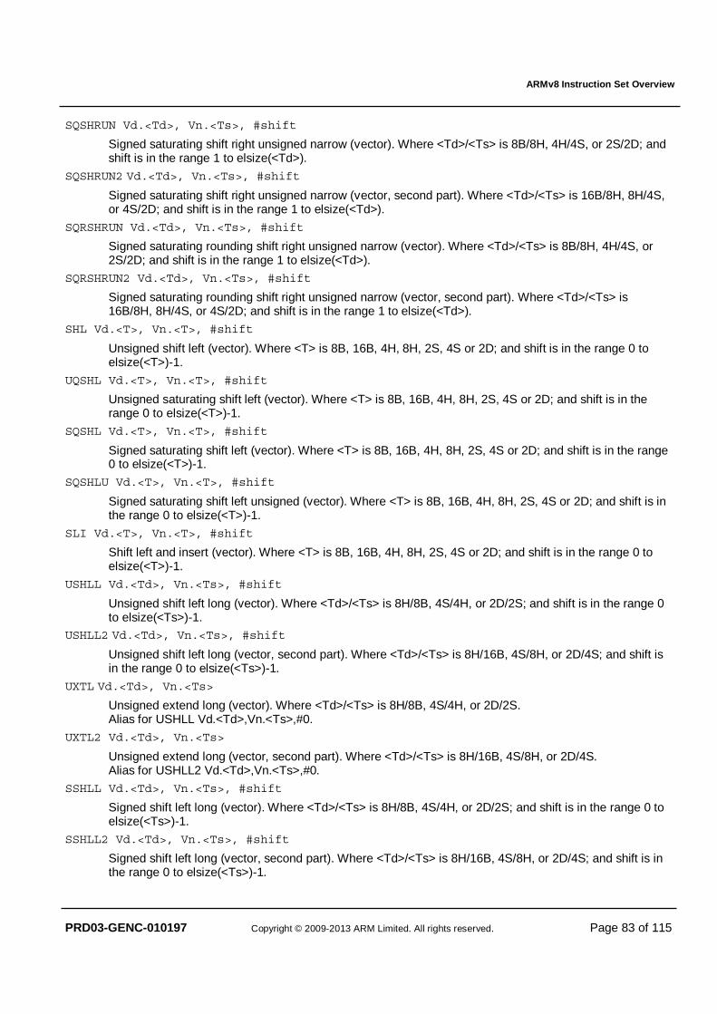
ARMv8 Instruction Set Overview
PRD03-GENC-010197 Copyright © 2009-2013 ARM Limited. All rights reserved. Page 83 of 115
SQSHRUN Vd.<Td>, Vn.<Ts>, #shift
Signed saturating shift right unsigned narrow (vector). Where <Td>/<Ts> is 8B/8H, 4H/4S, or 2S/2D; and shift is in the range 1 to elsize(<Td>).
SQSHRUN2 Vd.<Td>, Vn.<Ts>, #shift
Signed saturating shift right unsigned narrow (vector, second part). Where <Td>/<Ts> is 16B/8H, 8H/4S, or 4S/2D; and shift is in the range 1 to elsize(<Td>).
SQRSHRUN Vd.<Td>, Vn.<Ts>, #shift
Signed saturating rounding shift right unsigned narrow (vector). Where <Td>/<Ts> is 8B/8H, 4H/4S, or 2S/2D; and shift is in the range 1 to elsize(<Td>).
SQRSHRUN2 Vd.<Td>, Vn.<Ts>, #shift
Signed saturating rounding shift right unsigned narrow (vector, second part). Where <Td>/<Ts> is 16B/8H, 8H/4S, or 4S/2D; and shift is in the range 1 to elsize(<Td>).
SHL Vd.<T>, Vn.<T>, #shift
Unsigned shift left (vector). Where <T> is 8B, 16B, 4H, 8H, 2S, 4S or 2D; and shift is in the range 0 to elsize(<T>)-1.
UQSHL Vd.<T>, Vn.<T>, #shift
Unsigned saturating shift left (vector). Where <T> is 8B, 16B, 4H, 8H, 2S, 4S or 2D; and shift is in the range 0 to elsize(<T>)-1.
SQSHL Vd.<T>, Vn.<T>, #shift
Signed saturating shift left (vector). Where <T> is 8B, 16B, 4H, 8H, 2S, 4S or 2D; and shift is in the range 0 to elsize(<T>)-1.
SQSHLU Vd.<T>, Vn.<T>, #shift
Signed saturating shift left unsigned (vector). Where <T> is 8B, 16B, 4H, 8H, 2S, 4S or 2D; and shift is in the range 0 to elsize(<T>)-1.
SLI Vd.<T>, Vn.<T>, #shift
Shift left and insert (vector). Where <T> is 8B, 16B, 4H, 8H, 2S, 4S or 2D; and shift is in the range 0 to elsize(<T>)-1.
USHLL Vd.<Td>, Vn.<Ts>, #shift
Unsigned shift left long (vector). Where <Td>/<Ts> is 8H/8B, 4S/4H, or 2D/2S; and shift is in the range 0 to elsize(<Ts>)-1.
USHLL2 Vd.<Td>, Vn.<Ts>, #shift
Unsigned shift left long (vector, second part). Where <Td>/<Ts> is 8H/16B, 4S/8H, or 2D/4S; and shift is in the range 0 to elsize(<Ts>)-1.
UXTL Vd.<Td>, Vn.<Ts>
Unsigned extend long (vector). Where <Td>/<Ts> is 8H/8B, 4S/4H, or 2D/2S. Alias for USHLL Vd.<Td>,Vn.<Ts>,#0.
UXTL2 Vd.<Td>, Vn.<Ts>
Unsigned extend long (vector, second part). Where <Td>/<Ts> is 8H/16B, 4S/8H, or 2D/4S. Alias for USHLL2 Vd.<Td>,Vn.<Ts>,#0.
SSHLL Vd.<Td>, Vn.<Ts>, #shift
Signed shift left long (vector). Where <Td>/<Ts> is 8H/8B, 4S/4H, or 2D/2S; and shift is in the range 0 to elsize(<Ts>)-1.
SSHLL2 Vd.<Td>, Vn.<Ts>, #shift
Signed shift left long (vector, second part). Where <Td>/<Ts> is 8H/16B, 4S/8H, or 2D/4S; and shift is in the range 0 to elsize(<Ts>)-1.
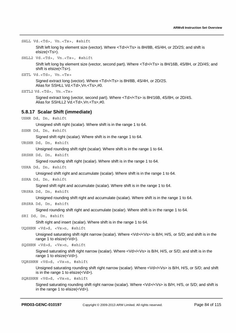
ARMv8 Instruction Set Overview
PRD03-GENC-010197 Copyright © 2009-2013 ARM Limited. All rights reserved. Page 84 of 115
SHLL Vd.<Td>, Vn.<Ts>, #shift
Shift left long by element size (vector). Where <Td>/<Ts> is 8H/8B, 4S/4H, or 2D/2S; and shift is elsize(<Ts>).
SHLL2 Vd.<Td>, Vn.<Ts>, #shift
Shift left long by element size (vector, second part). Where <Td>/<Ts> is 8H/16B, 4S/8H, or 2D/4S; and shift is elsize(<Ts>).
SXTL Vd.<Td>, Vn.<Ts>
Signed extract long (vector). Where <Td>/<Ts> is 8H/8B, 4S/4H, or 2D/2S. Alias for SSHLL Vd.<Td>,Vn.<Ts>,#0.
SXTL2 Vd.<Td>, Vn.<Ts>
Signed extract long (vector, second part). Where <Td>/<Ts> is 8H/16B, 4S/8H, or 2D/4S. Alias for SSHLL2 Vd.<Td>,Vn.<Ts>,#0.
5.8.17 Scalar Shift (immediate) USHR Dd, Dn, #shift
Unsigned shift right (scalar). Where shift is in the range 1 to 64.
SSHR Dd, Dn, #shift
Signed shift right (scalar). Where shift is in the range 1 to 64.
URSHR Dd, Dn, #shift
Unsigned rounding shift right (scalar). Where shift is in the range 1 to 64.
SRSHR Dd, Dn, #shift
Signed rounding shift right (scalar). Where shift is in the range 1 to 64.
USRA Dd, Dn, #shift
Unsigned shift right and accumulate (scalar). Where shift is in the range 1 to 64.
SSRA Dd, Dn, #shift
Signed shift right and accumulate (scalar). Where shift is in the range 1 to 64. URSRA Dd, Dn, #shift
Unsigned rounding shift right and accumulate (scalar). Where shift is in the range 1 to 64.
SRSRA Dd, Dn, #shift
Signed rounding shift right and accumulate (scalar). Where shift is in the range 1 to 64.
SRI Dd, Dn, #shift
Shift right and insert (scalar). Where shift is in the range 1 to 64.
UQSHRN <Vd>d, <Vs>n, #shift
Unsigned saturating shift right narrow (scalar). Where <Vd>/<Vs> is B/H, H/S, or S/D; and shift is in the range 1 to elsize(<Vd>).
SQSHRN <Vd>d, <Vs>n, #shift
Signed saturating shift right narrow (scalar). Where <Vd>/<Vs> is B/H, H/S, or S/D; and shift is in the range 1 to elsize(<Vd>).
UQRSHRN <Vd>d, <Vs>n, #shift
Unsigned saturating rounding shift right narrow (scalar). Where <Vd>/<Vs> is B/H, H/S, or S/D; and shift is in the range 1 to elsize(<Vd>).
SQRSHRN <Vd>d, <Vs>n, #shift
Signed saturating rounding shift right narrow (scalar). Where <Vd>/<Vs> is B/H, H/S, or S/D; and shift is in the range 1 to elsize(<Vd>).
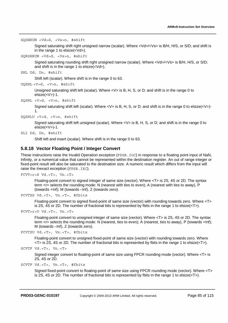
ARMv8 Instruction Set Overview
PRD03-GENC-010197 Copyright © 2009-2013 ARM Limited. All rights reserved. Page 85 of 115
SQSHRUN <Vd>d, <Vs>n, #shift
Signed saturating shift right unsigned narrow (scalar). Where <Vd>/<Vs> is B/H, H/S, or S/D; and shift is in the range 1 to elsize(<Vd>).
SQRSHRUN <Vd>d, <Vs>n, #shift
Signed saturating rounding shift right unsigned narrow (scalar). Where <Vd>/<Vs> is B/H, H/S, or S/D; and shift is in the range 1 to elsize(<Vd>).
SHL Dd, Dn, #shift
Shift left (scalar). Where shift is in the range 0 to 63.
UQSHL <V>d, <V>n, #shift
Unsigned saturating shift left (scalar). Where <V> is B, H, S, or D; and shift is in the range 0 to elsize(<V>)-1.
SQSHL <V>d, <V>n, #shift
Signed saturating shift left (scalar). Where <V> is B, H, S, or D; and shift is in the range 0 to elsize(<V>)-1.
SQSHLU <V>d, <V>n, #shift
Signed saturating shift left unsigned (scalar). Where <V> is B, H, S, or D; and shift is in the range 0 to elsize(<V>)-1.
SLI Dd, Dn, #shift
Shift left and insert (scalar). Where shift is in the range 0 to 63.
5.8.18 Vector Floating Point / Integer Convert These instructions raise the Invalid Operation exception (FPSR.IOC) in response to a floating point input of NaN, Infinity, or a numerical value that cannot be represented within the destination register. An out of range integer or fixed-point result will also be saturated to the destination size. A numeric result which differs from the input will raise the Inexact exception (FPSR.IXC).
FCVT<r>S Vd.<T>, Vn.<T>
Floating-point convert to signed integer of same size (vector). Where <T> is 2S, 4S or 2D. The syntax term <r> selects the rounding mode: N (nearest with ties to even); A (nearest with ties to away), P (towards +Inf); M (towards –Inf), Z (towards zero).
FCVTZS Vd.<T>, Vn.<T>, #fbits
Floating-point convert to signed fixed-point of same size (vector) with rounding towards zero. Where <T> is 2S, 4S or 2D. The number of fractional bits is represented by fbits in the range 1 to elsize(<T>).
FCVT<r>U Vd.<T>, Vn.<T>
Floating-point convert to unsigned integer of same size (vector). Where <T> is 2S, 4S or 2D. The syntax term <r> selects the rounding mode: N (nearest, ties to even); A (nearest, ties to away), P (towards +Inf); M (towards –Inf), Z (towards zero).
FCVTZU Vd.<T>, Vn.<T>, #fbits
Floating-point convert to unsigned fixed-point of same size (vector) with rounding towards zero. Where <T> is 2S, 4S or 2D. The number of fractional bits is represented by fbits in the range 1 to elsize(<T>).
SCVTF Vd.<T>, Vn.<T>
Signed integer convert to floating-point of same size using FPCR rounding mode (vector). Where <T> is 2S, 4S or 2D.
SCVTF Vd.<T>, Vn.<T>, #fbits
Signed fixed-point convert to floating-point of same size using FPCR rounding mode (vector). Where <T> is 2S, 4S or 2D. The number of fractional bits is represented by fbits in the range 1 to elsize(<T>).
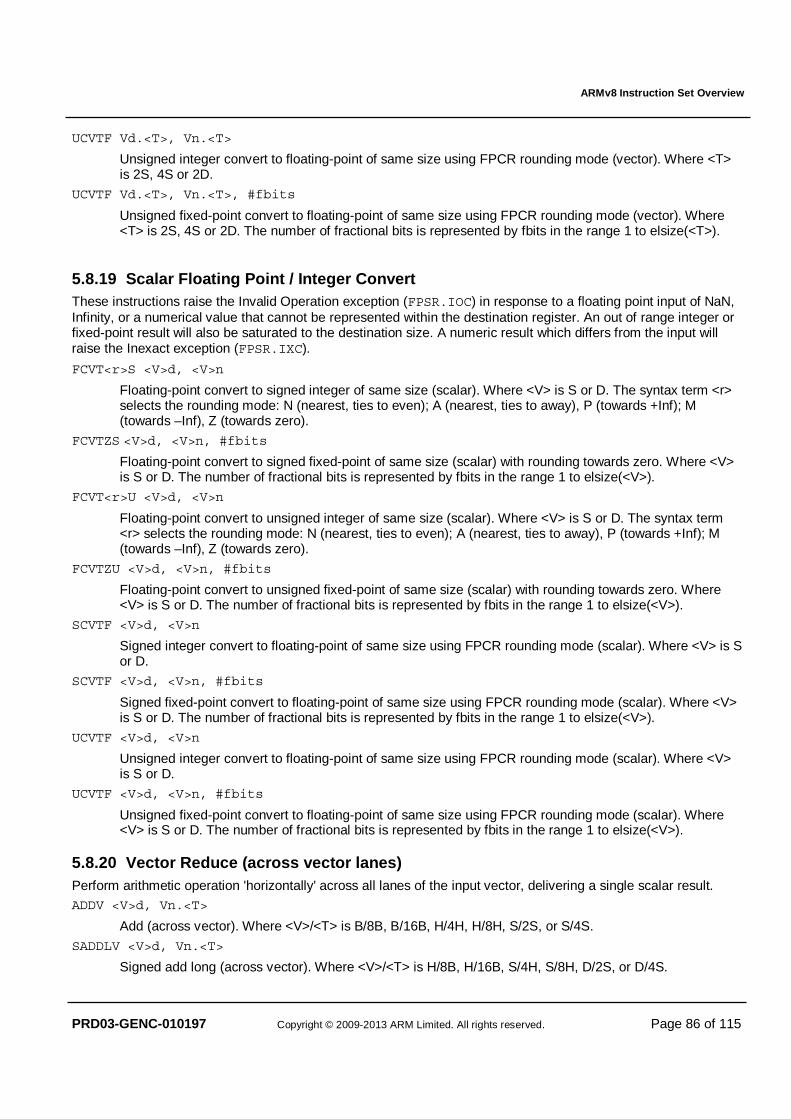
ARMv8 Instruction Set Overview
PRD03-GENC-010197 Copyright © 2009-2013 ARM Limited. All rights reserved. Page 86 of 115
UCVTF Vd.<T>, Vn.<T>
Unsigned integer convert to floating-point of same size using FPCR rounding mode (vector). Where <T> is 2S, 4S or 2D.
UCVTF Vd.<T>, Vn.<T>, #fbits
Unsigned fixed-point convert to floating-point of same size using FPCR rounding mode (vector). Where <T> is 2S, 4S or 2D. The number of fractional bits is represented by fbits in the range 1 to elsize(<T>).
5.8.19 Scalar Floating Point / Integer Convert These instructions raise the Invalid Operation exception (FPSR.IOC) in response to a floating point input of NaN, Infinity, or a numerical value that cannot be represented within the destination register. An out of range integer or fixed-point result will also be saturated to the destination size. A numeric result which differs from the input will raise the Inexact exception (FPSR.IXC).
FCVT<r>S <V>d, <V>n
Floating-point convert to signed integer of same size (scalar). Where <V> is S or D. The syntax term <r> selects the rounding mode: N (nearest, ties to even); A (nearest, ties to away), P (towards +Inf); M (towards –Inf), Z (towards zero).
FCVTZS <V>d, <V>n, #fbits
Floating-point convert to signed fixed-point of same size (scalar) with rounding towards zero. Where <V> is S or D. The number of fractional bits is represented by fbits in the range 1 to elsize(<V>).
FCVT<r>U <V>d, <V>n
Floating-point convert to unsigned integer of same size (scalar). Where <V> is S or D. The syntax term <r> selects the rounding mode: N (nearest, ties to even); A (nearest, ties to away), P (towards +Inf); M (towards –Inf), Z (towards zero).
FCVTZU <V>d, <V>n, #fbits
Floating-point convert to unsigned fixed-point of same size (scalar) with rounding towards zero. Where <V> is S or D. The number of fractional bits is represented by fbits in the range 1 to elsize(<V>).
SCVTF <V>d, <V>n
Signed integer convert to floating-point of same size using FPCR rounding mode (scalar). Where <V> is S or D.
SCVTF <V>d, <V>n, #fbits
Signed fixed-point convert to floating-point of same size using FPCR rounding mode (scalar). Where <V> is S or D. The number of fractional bits is represented by fbits in the range 1 to elsize(<V>).
UCVTF <V>d, <V>n
Unsigned integer convert to floating-point of same size using FPCR rounding mode (scalar). Where <V> is S or D.
UCVTF <V>d, <V>n, #fbits
Unsigned fixed-point convert to floating-point of same size using FPCR rounding mode (scalar). Where <V> is S or D. The number of fractional bits is represented by fbits in the range 1 to elsize(<V>).
5.8.20 Vector Reduce (across vector lanes) Perform arithmetic operation 'horizontally' across all lanes of the input vector, delivering a single scalar result. ADDV <V>d, Vn.<T>
Add (across vector). Where <V>/<T> is B/8B, B/16B, H/4H, H/8H, S/2S, or S/4S.
SADDLV <V>d, Vn.<T>
Signed add long (across vector). Where <V>/<T> is H/8B, H/16B, S/4H, S/8H, D/2S, or D/4S.
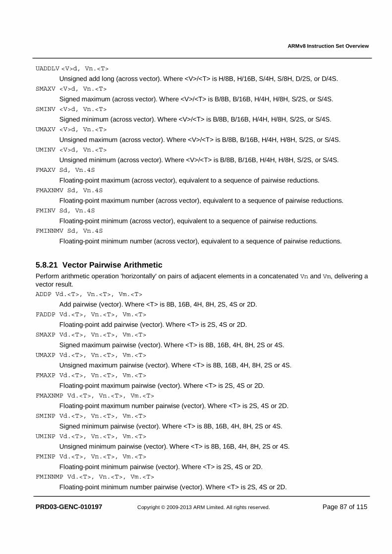
ARMv8 Instruction Set Overview
PRD03-GENC-010197 Copyright © 2009-2013 ARM Limited. All rights reserved. Page 87 of 115
UADDLV <V>d, Vn.<T>
Unsigned add long (across vector). Where <V>/<T> is H/8B, H/16B, S/4H, S/8H, D/2S, or D/4S.
SMAXV <V>d, Vn.<T>
Signed maximum (across vector). Where <V>/<T> is B/8B, B/16B, H/4H, H/8H, S/2S, or S/4S.
SMINV <V>d, Vn.<T>
Signed minimum (across vector). Where <V>/<T> is B/8B, B/16B, H/4H, H/8H, S/2S, or S/4S.
UMAXV <V>d, Vn.<T>
Unsigned maximum (across vector). Where <V>/<T> is B/8B, B/16B, H/4H, H/8H, S/2S, or S/4S.
UMINV <V>d, Vn.<T>
Unsigned minimum (across vector). Where <V>/<T> is B/8B, B/16B, H/4H, H/8H, S/2S, or S/4S.
FMAXV Sd, Vn.4S
Floating-point maximum (across vector), equivalent to a sequence of pairwise reductions.
FMAXNMV Sd, Vn.4S
Floating-point maximum number (across vector), equivalent to a sequence of pairwise reductions.
FMINV Sd, Vn.4S
Floating-point minimum (across vector), equivalent to a sequence of pairwise reductions. FMINNMV Sd, Vn.4S
Floating-point minimum number (across vector), equivalent to a sequence of pairwise reductions.
5.8.21 Vector Pairwise Arithmetic Perform arithmetic operation 'horizontally' on pairs of adjacent elements in a concatenated Vn and Vm, delivering a vector result. ADDP Vd.<T>, Vn.<T>, Vm.<T>
Add pairwise (vector). Where <T> is 8B, 16B, 4H, 8H, 2S, 4S or 2D.
FADDP Vd.<T>, Vn.<T>, Vm.<T>
Floating-point add pairwise (vector). Where <T> is 2S, 4S or 2D.
SMAXP Vd.<T>, Vn.<T>, Vm.<T>
Signed maximum pairwise (vector). Where <T> is 8B, 16B, 4H, 8H, 2S or 4S.
UMAXP Vd.<T>, Vn.<T>, Vm.<T>
Unsigned maximum pairwise (vector). Where <T> is 8B, 16B, 4H, 8H, 2S or 4S.
FMAXP Vd.<T>, Vn.<T>, Vm.<T>
Floating-point maximum pairwise (vector). Where <T> is 2S, 4S or 2D.
FMAXNMP Vd.<T>, Vn.<T>, Vm.<T>
Floating-point maximum number pairwise (vector). Where <T> is 2S, 4S or 2D.
SMINP Vd.<T>, Vn.<T>, Vm.<T>
Signed minimum pairwise (vector). Where <T> is 8B, 16B, 4H, 8H, 2S or 4S.
UMINP Vd.<T>, Vn.<T>, Vm.<T>
Unsigned minimum pairwise (vector). Where <T> is 8B, 16B, 4H, 8H, 2S or 4S.
FMINP Vd.<T>, Vn.<T>, Vm.<T>
Floating-point minimum pairwise (vector). Where <T> is 2S, 4S or 2D. FMINNMP Vd.<T>, Vn.<T>, Vm.<T>
Floating-point minimum number pairwise (vector). Where <T> is 2S, 4S or 2D.
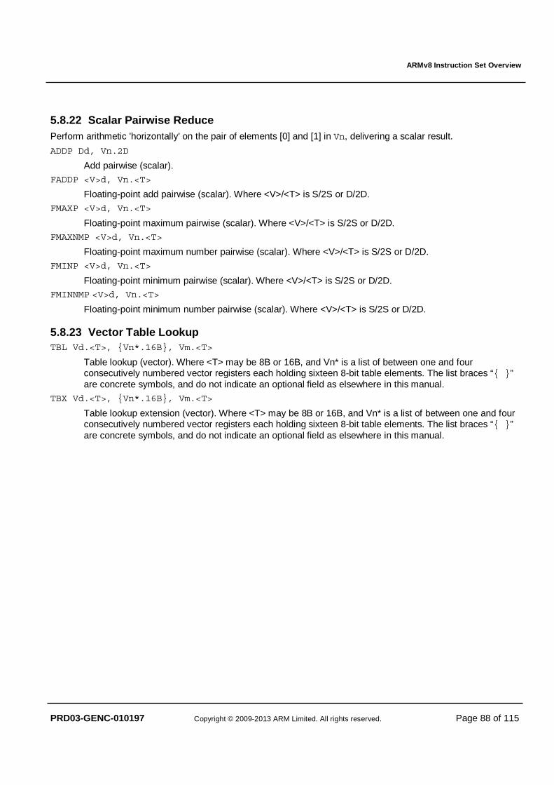
ARMv8 Instruction Set Overview
PRD03-GENC-010197 Copyright © 2009-2013 ARM Limited. All rights reserved. Page 88 of 115
5.8.22 Scalar Pairwise Reduce Perform arithmetic 'horizontally' on the pair of elements [0] and [1] in Vn, delivering a scalar result.
ADDP Dd, Vn.2D
Add pairwise (scalar).
FADDP <V>d, Vn.<T>
Floating-point add pairwise (scalar). Where <V>/<T> is S/2S or D/2D.
FMAXP <V>d, Vn.<T>
Floating-point maximum pairwise (scalar). Where <V>/<T> is S/2S or D/2D.
FMAXNMP <V>d, Vn.<T>
Floating-point maximum number pairwise (scalar). Where <V>/<T> is S/2S or D/2D.
FMINP <V>d, Vn.<T>
Floating-point minimum pairwise (scalar). Where <V>/<T> is S/2S or D/2D. FMINNMP <V>d, Vn.<T>
Floating-point minimum number pairwise (scalar). Where <V>/<T> is S/2S or D/2D.
5.8.23 Vector Table Lookup TBL Vd.<T>, {Vn*.16B}, Vm.<T>
Table lookup (vector). Where <T> may be 8B or 16B, and Vn* is a list of between one and four consecutively numbered vector registers each holding sixteen 8-bit table elements. The list braces “{ }” are concrete symbols, and do not indicate an optional field as elsewhere in this manual.
TBX Vd.<T>, {Vn*.16B}, Vm.<T>
Table lookup extension (vector). Where <T> may be 8B or 16B, and Vn* is a list of between one and four consecutively numbered vector registers each holding sixteen 8-bit table elements. The list braces “{ }” are concrete symbols, and do not indicate an optional field as elsewhere in this manual.
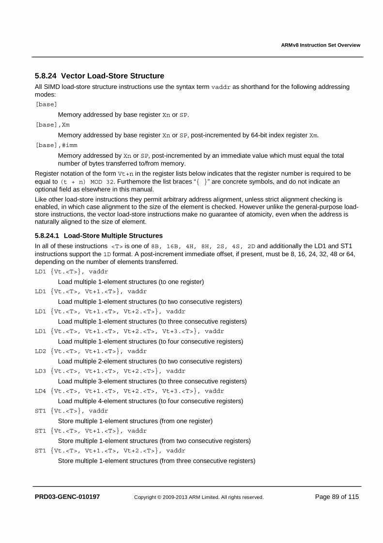
ARMv8 Instruction Set Overview
PRD03-GENC-010197 Copyright © 2009-2013 ARM Limited. All rights reserved. Page 89 of 115
5.8.24 Vector Load-Store Structure All SIMD load-store structure instructions use the syntax term vaddr as shorthand for the following addressing modes:
[base]
Memory addressed by base register Xn or SP.
[base],Xm
Memory addressed by base register Xn or SP, post-incremented by 64-bit index register Xm.
[base],#imm
Memory addressed by Xn or SP, post-incremented by an immediate value which must equal the total number of bytes transferred to/from memory.
Register notation of the form Vt+n in the register lists below indicates that the register number is required to be equal to (t + n) MOD 32. Furthemore the list braces “{ }” are concrete symbols, and do not indicate an optional field as elsewhere in this manual.
Like other load-store instructions they permit arbitrary address alignment, unless strict alignment checking is enabled, in which case alignment to the size of the element is checked. However unlike the general-purpose load-store instructions, the vector load-store instructions make no guarantee of atomicity, even when the address is naturally aligned to the size of element.
5.8.24.1 Load-Store Multiple Structures
In all of these instructions <T> is one of 8B, 16B, 4H, 8H, 2S, 4S, 2D and additionally the LD1 and ST1 instructions support the 1D format. A post-increment immediate offset, if present, must be 8, 16, 24, 32, 48 or 64, depending on the number of elements transferred.
LD1 {Vt.<T>}, vaddr
Load multiple 1-element structures (to one register) LD1 {Vt.<T>, Vt+1.<T>}, vaddr
Load multiple 1-element structures (to two consecutive registers)
LD1 {Vt.<T>, Vt+1.<T>, Vt+2.<T>}, vaddr
Load multiple 1-element structures (to three consecutive registers)
LD1 {Vt.<T>, Vt+1.<T>, Vt+2.<T>, Vt+3.<T>}, vaddr
Load multiple 1-element structures (to four consecutive registers)
LD2 {Vt.<T>, Vt+1.<T>}, vaddr
Load multiple 2-element structures (to two consecutive registers)
LD3 {Vt.<T>, Vt+1.<T>, Vt+2.<T>}, vaddr
Load multiple 3-element structures (to three consecutive registers)
LD4 {Vt.<T>, Vt+1.<T>, Vt+2.<T>, Vt+3.<T>}, vaddr
Load multiple 4-element structures (to four consecutive registers)
ST1 {Vt.<T>}, vaddr
Store multiple 1-element structures (from one register)
ST1 {Vt.<T>, Vt+1.<T>}, vaddr
Store multiple 1-element structures (from two consecutive registers)
ST1 {Vt.<T>, Vt+1.<T>, Vt+2.<T>}, vaddr
Store multiple 1-element structures (from three consecutive registers)
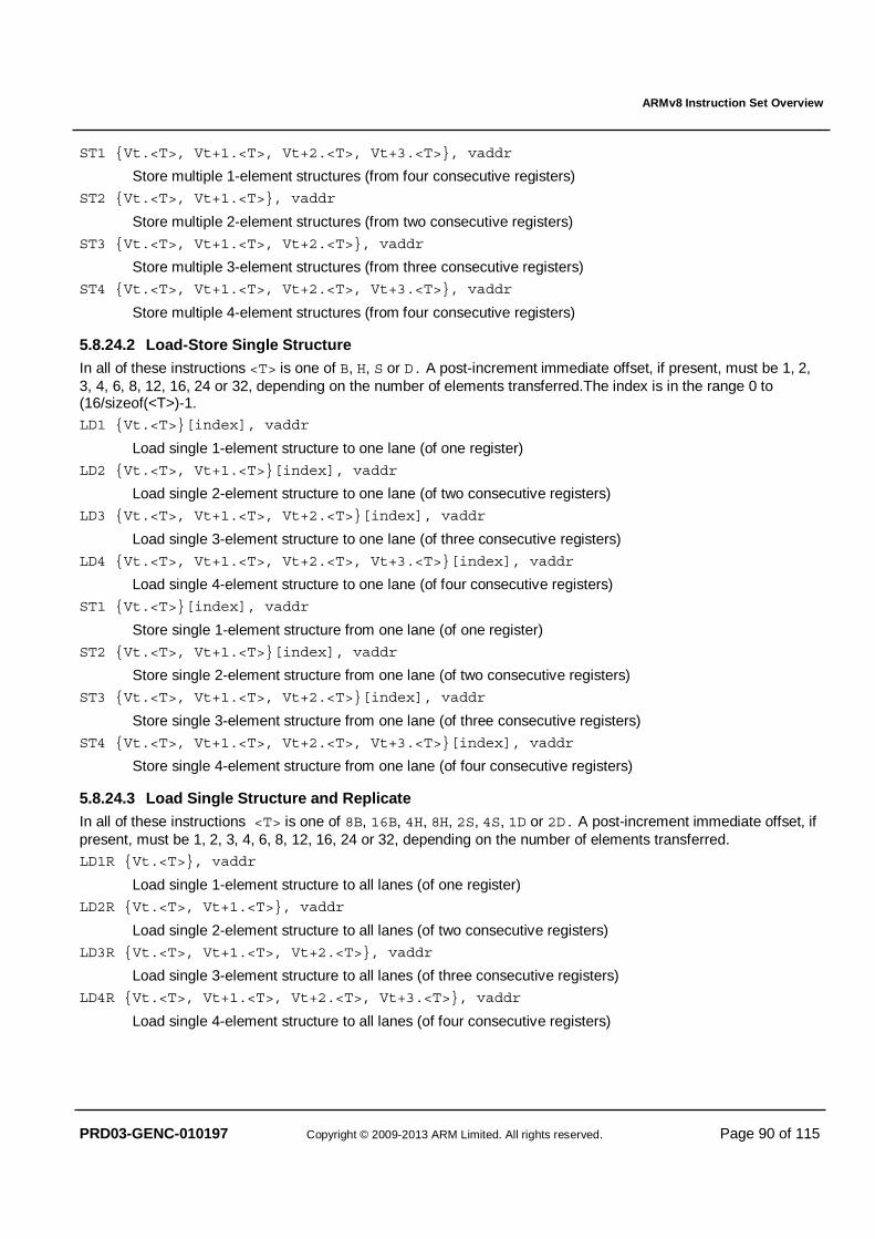
ARMv8 Instruction Set Overview
PRD03-GENC-010197 Copyright © 2009-2013 ARM Limited. All rights reserved. Page 90 of 115
ST1 {Vt.<T>, Vt+1.<T>, Vt+2.<T>, Vt+3.<T>}, vaddr
Store multiple 1-element structures (from four consecutive registers)
ST2 {Vt.<T>, Vt+1.<T>}, vaddr
Store multiple 2-element structures (from two consecutive registers)
ST3 {Vt.<T>, Vt+1.<T>, Vt+2.<T>}, vaddr
Store multiple 3-element structures (from three consecutive registers)
ST4 {Vt.<T>, Vt+1.<T>, Vt+2.<T>, Vt+3.<T>}, vaddr
Store multiple 4-element structures (from four consecutive registers)
5.8.24.2 Load-Store Single Structure In all of these instructions <T> is one of B, H, S or D. A post-increment immediate offset, if present, must be 1, 2, 3, 4, 6, 8, 12, 16, 24 or 32, depending on the number of elements transferred.The index is in the range 0 to (16/sizeof(<T>)-1. LD1 {Vt.<T>}[index], vaddr
Load single 1-element structure to one lane (of one register)
LD2 {Vt.<T>, Vt+1.<T>}[index], vaddr
Load single 2-element structure to one lane (of two consecutive registers)
LD3 {Vt.<T>, Vt+1.<T>, Vt+2.<T>}[index], vaddr
Load single 3-element structure to one lane (of three consecutive registers)
LD4 {Vt.<T>, Vt+1.<T>, Vt+2.<T>, Vt+3.<T>}[index], vaddr
Load single 4-element structure to one lane (of four consecutive registers)
ST1 {Vt.<T>}[index], vaddr
Store single 1-element structure from one lane (of one register)
ST2 {Vt.<T>, Vt+1.<T>}[index], vaddr
Store single 2-element structure from one lane (of two consecutive registers)
ST3 {Vt.<T>, Vt+1.<T>, Vt+2.<T>}[index], vaddr
Store single 3-element structure from one lane (of three consecutive registers)
ST4 {Vt.<T>, Vt+1.<T>, Vt+2.<T>, Vt+3.<T>}[index], vaddr
Store single 4-element structure from one lane (of four consecutive registers)
5.8.24.3 Load Single Structure and Replicate In all of these instructions <T> is one of 8B, 16B, 4H, 8H, 2S, 4S, 1D or 2D. A post-increment immediate offset, if present, must be 1, 2, 3, 4, 6, 8, 12, 16, 24 or 32, depending on the number of elements transferred. LD1R {Vt.<T>}, vaddr
Load single 1-element structure to all lanes (of one register)
LD2R {Vt.<T>, Vt+1.<T>}, vaddr
Load single 2-element structure to all lanes (of two consecutive registers)
LD3R {Vt.<T>, Vt+1.<T>, Vt+2.<T>}, vaddr
Load single 3-element structure to all lanes (of three consecutive registers)
LD4R {Vt.<T>, Vt+1.<T>, Vt+2.<T>, Vt+3.<T>}, vaddr
Load single 4-element structure to all lanes (of four consecutive registers)
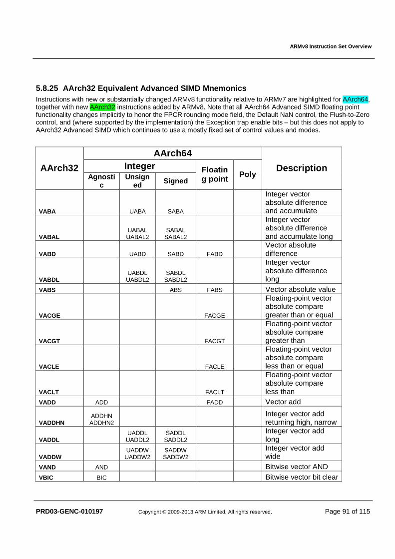
ARMv8 Instruction Set Overview
PRD03-GENC-010197 Copyright © 2009-2013 ARM Limited. All rights reserved. Page 91 of 115
5.8.25 AArch32 Equivalent Advanced SIMD Mnemonics Instructions with new or substantially changed ARMv8 functionality relative to ARMv7 are highlighted for AArch64, together with new AArch32 instructions added by ARMv8. Note that all AArch64 Advanced SIMD floating point functionality changes implicitly to honor the FPCR rounding mode field, the Default NaN control, the Flush-to-Zero control, and (where supported by the implementation) the Exception trap enable bits – but this does not apply to AArch32 Advanced SIMD which continues to use a mostly fixed set of control values and modes.
AArch64 Integer AArch32
Agnostic
Unsigned Signed
Floating point Poly
Description
VABA UABA SABA
Integer vector absolute difference and accumulate
VABAL UABAL UABAL2
SABAL SABAL2
Integer vector absolute difference and accumulate long
VABD UABD SABD FABD Vector absolute difference
VABDL UABDL UABDL2
SABDL SABDL2
Integer vector absolute difference long
VABS ABS FABS Vector absolute value
VACGE FACGE
Floating-point vector absolute compare greater than or equal
VACGT FACGT
Floating-point vector absolute compare greater than
VACLE FACLE
Floating-point vector absolute compare less than or equal
VACLT FACLT
Floating-point vector absolute compare less than
VADD ADD FADD Vector add
VADDHN ADDHN ADDHN2
Integer vector add returning high, narrow
VADDL UADDL UADDL2
SADDL SADDL2
Integer vector add long
VADDW UADDW
UADDW2 SADDW SADDW2
Integer vector add wide
VAND AND Bitwise vector AND VBIC BIC Bitwise vector bit clear
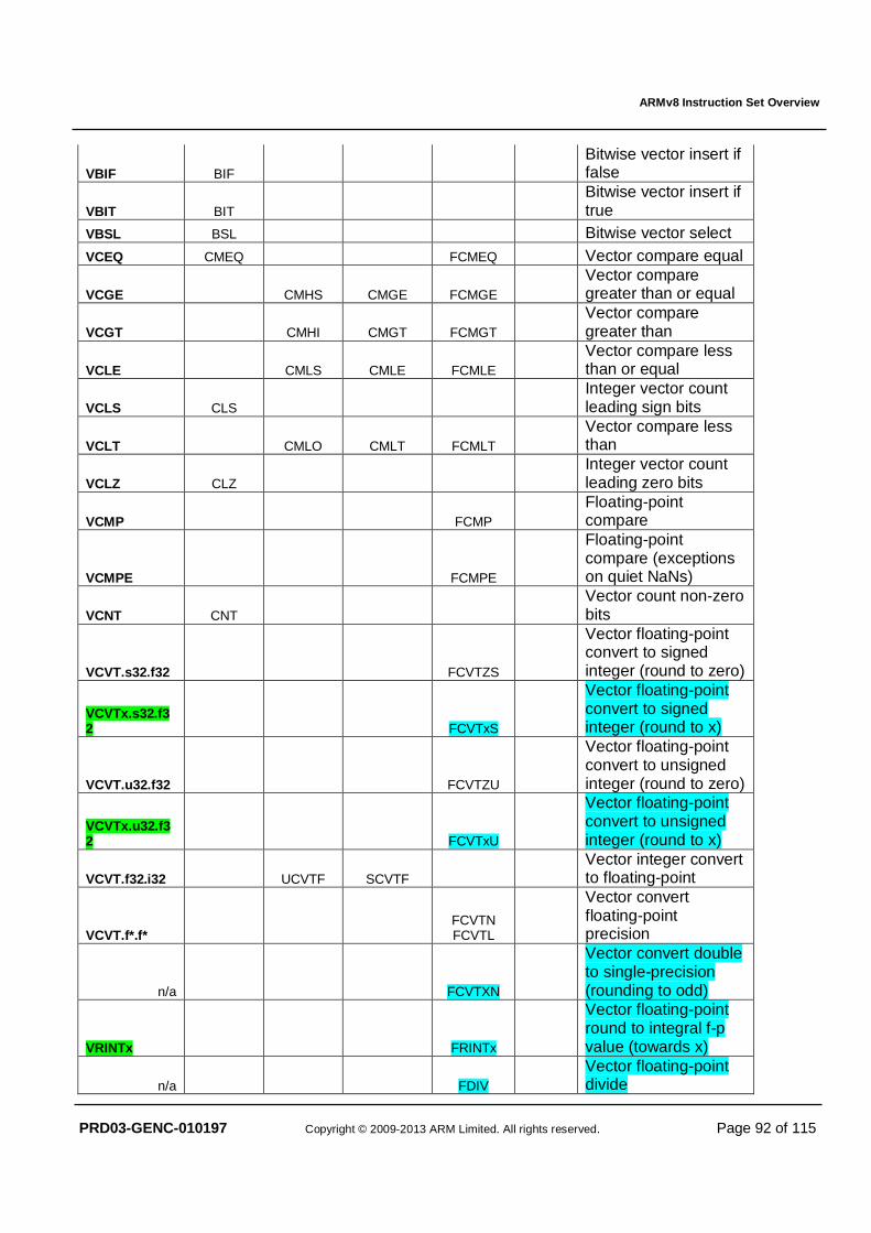
ARMv8 Instruction Set Overview
PRD03-GENC-010197 Copyright © 2009-2013 ARM Limited. All rights reserved. Page 92 of 115
VBIF BIF Bitwise vector insert if false
VBIT BIT Bitwise vector insert if true
VBSL BSL Bitwise vector select VCEQ CMEQ FCMEQ Vector compare equal
VCGE CMHS CMGE FCMGE Vector compare greater than or equal
VCGT CMHI CMGT FCMGT Vector compare greater than
VCLE CMLS CMLE FCMLE Vector compare less than or equal
VCLS CLS Integer vector count leading sign bits
VCLT CMLO CMLT FCMLT Vector compare less than
VCLZ CLZ Integer vector count leading zero bits
VCMP FCMP Floating-point compare
VCMPE FCMPE
Floating-point compare (exceptions on quiet NaNs)
VCNT CNT Vector count non-zero bits
VCVT.s32.f32 FCVTZS
Vector floating-point convert to signed integer (round to zero)
VCVTx.s32.f32 FCVTxS
Vector floating-point convert to signed integer (round to x)
VCVT.u32.f32 FCVTZU
Vector floating-point convert to unsigned integer (round to zero)
VCVTx.u32.f32 FCVTxU
Vector floating-point convert to unsigned integer (round to x)
VCVT.f32.i32 UCVTF SCVTF Vector integer convert to floating-point
VCVT.f*.f* FCVTN FCVTL
Vector convert floating-point precision
n/a FCVTXN
Vector convert double to single-precision (rounding to odd)
VRINTx FRINTx
Vector floating-point round to integral f-p value (towards x)
n/a FDIV Vector floating-point divide
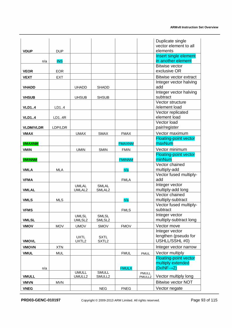
ARMv8 Instruction Set Overview
PRD03-GENC-010197 Copyright © 2009-2013 ARM Limited. All rights reserved. Page 93 of 115
VDUP DUP
Duplicate single vector element to all elements
n/a INS Insert single element in another element
VEOR EOR Bitwise vector exclusive OR
VEXT EXT Bitwise vector extract
VHADD UHADD SHADD Integer vector halving add
VHSUB UHSUB SHSUB Integer vector halving subtract
VLD1..4 LD1..4 Vector structure /element load
VLD1..4 LD1..4R Vector replicated element load
VLDM/VLDR LDP/LDR Vector load pair/register
VMAX UMAX SMAX FMAX Vector maximum
VMAXNM FMAXNM Floating-point vector maxNum
VMIN UMIN SMIN FMIN Vector minimum
VMINNM FMINNM Floating-point vector minNum
VMLA MLA n/a Vector chained multiply-add
VFMA FMLA Vector fused multiply-add
VMLAL UMLAL UMLAL2
SMLAL SMLAL2
Integer vector multiply-add long
VMLS MLS n/a Vector chained multiply-subtract
VFMS FMLS Vector fused multiply-subtract
VMLSL UMLSL UMLSL2
SMLSL SMLSL2
Integer vector multiply-subtract long
VMOV MOV UMOV SMOV FMOV Vector move
VMOVL UXTL
UXTL2 SXTL SXTL2
Integer vector lengthen (pseudo for USHLL/SSHL #0)
VMOVN XTN Integer vector narrow VMUL MUL FMUL PMUL Vector multiply
n/a FMULX
Floating-point vector multiply extended (0xINF→2)
VMULL UMULL UMULL2
SMULL SMULL2
PMULL PMULL2 Vector multiply long
VMVN MVN Bitwise vector NOT VNEG NEG FNEG Vector negate
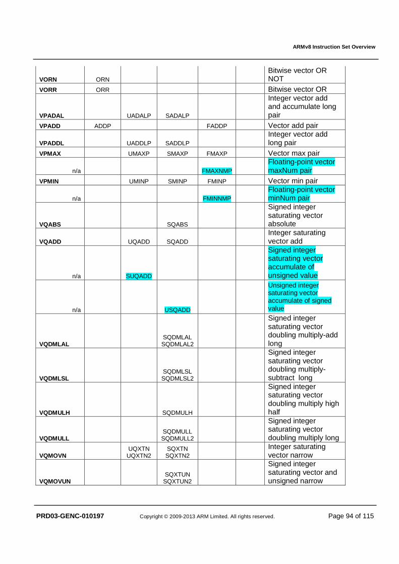
ARMv8 Instruction Set Overview
PRD03-GENC-010197 Copyright © 2009-2013 ARM Limited. All rights reserved. Page 94 of 115
VORN ORN Bitwise vector OR NOT
VORR ORR Bitwise vector OR
VPADAL UADALP SADALP
Integer vector add and accumulate long pair
VPADD ADDP FADDP Vector add pair
VPADDL UADDLP SADDLP Integer vector add long pair
VPMAX UMAXP SMAXP FMAXP Vector max pair
n/a FMAXNMP Floating-point vector maxNum pair
VPMIN UMINP SMINP FMINP Vector min pair
n/a FMINNMP Floating-point vector minNum pair
VQABS SQABS
Signed integer saturating vector absolute
VQADD UQADD SQADD Integer saturating vector add
n/a SUQADD
Signed integer saturating vector accumulate of unsigned value
n/a USQADD
Unsigned integer saturating vector accumulate of signed value
VQDMLAL SQDMLAL SQDMLAL2
Signed integer saturating vector doubling multiply-add long
VQDMLSL SQDMLSL SQDMLSL2
Signed integer saturating vector doubling multiply-subtract long
VQDMULH SQDMULH
Signed integer saturating vector doubling multiply high half
VQDMULL SQDMULL SQDMULL2
Signed integer saturating vector doubling multiply long
VQMOVN UQXTN
UQXTN2 SQXTN SQXTN2
Integer saturating vector narrow
VQMOVUN SQXTUN
SQXTUN2
Signed integer saturating vector and unsigned narrow
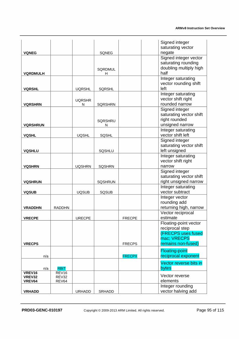
ARMv8 Instruction Set Overview
PRD03-GENC-010197 Copyright © 2009-2013 ARM Limited. All rights reserved. Page 95 of 115
VQNEG SQNEG
Signed integer saturating vector negate
VQRDMULH SQRDMUL
H
Signed integer vector saturating rounding doubling multiply high half
VQRSHL UQRSHL SQRSHL
Integer saturating vector rounding shift left
VQRSHRN UQRSHR
N SQRSHRN
Integer saturating vector shift right rounded narrow
VQRSHRUN SQRSHRU
N
Signed integer saturating vector shift right rounded unsigned narrow
VQSHL UQSHL SQSHL Integer saturating vector shift left
VQSHLU SQSHLU
Signed integer saturating vector shift left unsigned
VQSHRN UQSHRN SQSHRN
Integer saturating vector shift right narrow
VQSHRUN SQSHRUN
Signed integer saturating vector shift right unsigned narrow
VQSUB UQSUB SQSUB Integer saturating vector subtract
VRADDHN RADDHN
Integer vector rounding add returning high, narrow
VRECPE URECPE FRECPE Vector reciprocal estimate
VRECPS FRECPS
Floating-point vector reciprocal step (FRECPS uses fused mac; VRECPS remains non-fused)
n/a FRECPX Floating-point reciprocal exponent
n/a RBIT Vector reverse bits in bytes
VREV16 VREV32 VREV64
REV16 REV32 REV64
Vector reverse elements
VRHADD URHADD SRHADD Integer rounding vector halving add
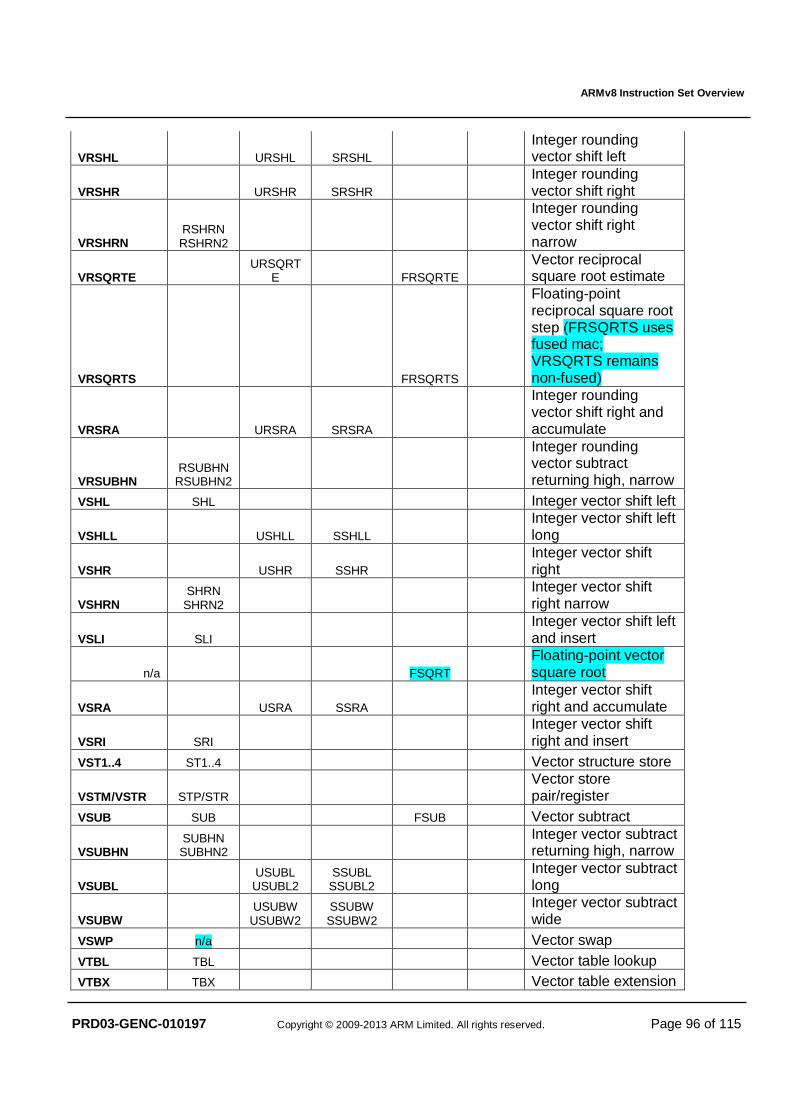
ARMv8 Instruction Set Overview
PRD03-GENC-010197 Copyright © 2009-2013 ARM Limited. All rights reserved. Page 96 of 115
VRSHL URSHL SRSHL Integer rounding vector shift left
VRSHR URSHR SRSHR Integer rounding vector shift right
VRSHRN RSHRN RSHRN2
Integer rounding vector shift right narrow
VRSQRTE URSQRT
E FRSQRTE Vector reciprocal square root estimate
VRSQRTS FRSQRTS
Floating-point reciprocal square root step (FRSQRTS uses fused mac; VRSQRTS remains non-fused)
VRSRA URSRA SRSRA
Integer rounding vector shift right and accumulate
VRSUBHN RSUBHN
RSUBHN2
Integer rounding vector subtract returning high, narrow
VSHL SHL Integer vector shift left
VSHLL USHLL SSHLL Integer vector shift left long
VSHR USHR SSHR Integer vector shift right
VSHRN SHRN
SHRN2 Integer vector shift right narrow
VSLI SLI Integer vector shift left and insert
n/a FSQRT Floating-point vector square root
VSRA USRA SSRA Integer vector shift right and accumulate
VSRI SRI Integer vector shift right and insert
VST1..4 ST1..4 Vector structure store
VSTM/VSTR STP/STR Vector store pair/register
VSUB SUB FSUB Vector subtract
VSUBHN SUBHN SUBHN2
Integer vector subtract returning high, narrow
VSUBL USUBL USUBL2
SSUBL SSUBL2
Integer vector subtract long
VSUBW USUBW
USUBW2 SSUBW SSUBW2
Integer vector subtract wide
VSWP n/a Vector swap VTBL TBL Vector table lookup VTBX TBX Vector table extension
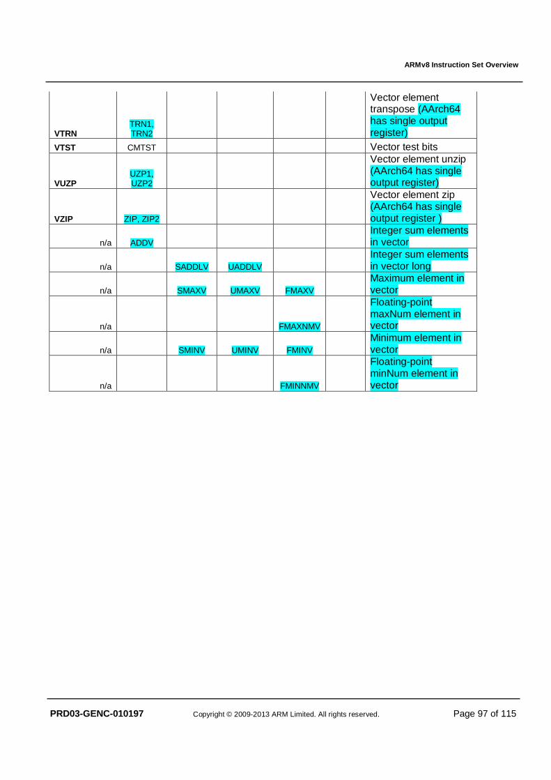
ARMv8 Instruction Set Overview
PRD03-GENC-010197 Copyright © 2009-2013 ARM Limited. All rights reserved. Page 97 of 115
VTRN TRN1, TRN2
Vector element transpose (AArch64 has single output register)
VTST CMTST Vector test bits
VUZP UZP1, UZP2
Vector element unzip (AArch64 has single output register)
VZIP ZIP, ZIP2
Vector element zip (AArch64 has single output register )
n/a ADDV Integer sum elements in vector
n/a SADDLV UADDLV Integer sum elements in vector long
n/a SMAXV UMAXV FMAXV Maximum element in vector
n/a FMAXNMV
Floating-point maxNum element in vector
n/a SMINV UMINV FMINV Minimum element in vector
n/a FMINNMV
Floating-point minNum element in vector
ARMv8 Instruction Set Overview
PRD03-GENC-010197 Copyright © 2009-2013 ARM Limited. All rights reserved. Page 98 of 115
5.8.26 Crypto Extension The optional Crypto extension shares the FP/SIMD register file. For more information see [AES], [GCM] and [SHA].
PMULL Vd.1Q, Vn.1D, Vm.1D
Polynomial multiply long): AES-GCM acceleration 64x64 to 128-bit.
PMULL2 Vd.1Q, Vn.2D, Vm.2D
Polynomial multiply long (second part). Upper lanes AES-GCM acceleration 64x64 to 128-bit.
AESE Vd.16B, Vn.16B
AES single round encryption.
AESD Vd.16B, Vn.16B
AES single round decryption.
AESMC Vd.16B, Vn.16B
AES mix columns.
AESIMC Vd.16B, Vn.16B
AES inverse mix columns.
SHA256H Qd, Qn, Vm.4S
SHA256 hash update accelerator.
SHA256H2 Qd, Qn, Vm.4S
SHA256 hash update accelerator, upper part.
SHA256SU0 Vd.4S, Vn.4S
SHA256 schedule update accelerator, first part SHA256SU1 Vd.4S, Vn.4S, Vm.4S
SHA256 schedule update accelerator, second part
SHA1C Qd, Sn, Vm.4S
SHA1 hash update accelerator (choose).
SHA1P Qd, Sn, Vm.4S
SHA1 hash update accelerator (parity).
SHA1M Qd, Sn, Vm.4S
SHA1 hash update accelerator (majority).
SHA1H Sd, Sn
SHA1 hash update accelerator (rotate left by 30).
SHA1SU0 Vd.4S, Vn.4S, Vm.4S
SHA1 schedule update accelerator, first part
SHA1SU1 Vd.4S, Vn.4S
SHA1 schedule update accelerator, second part
ARMv8 Instruction Set Overview
PRD03-GENC-010197 Copyright © 2009-2013 ARM Limited. All rights reserved. Page 99 of 115
5.9 System Instructions The following instruction groups are supported:
• Exception generating instructions
• System register access
• System management
• Architectural hints
• Barriers and CLREX
In several of the system instructions described in this section, the following terms are used to describe operands:
op0
A 2-bit opcode field with an immediate value 2 or 3. op1, op2
A 3-bit opcode field with an immediate value in the range 0 to 7. Cn
A 4-bit opcode field named for historical reasons C0 – C15.
Cm
A 4-bit opcode field named for historical reasons C0 – C15.
5.9.1 Exception Generation and Return
5.9.1.1 Non-debug exceptions SVC #uimm16
Generate exception targeted at exception level 1 (system), with 16-bit payload in uimm16.
HVC #uimm16
Generate exception targeted at exception level 2 (hypervisor) , with 16-bit payload in uimm16.
SMC #uimm16
Generate exception targeted at exception level 3 (secure monitor), with 16-bit payload in uimm16.
ERET
Exception return: reconstructs the processor state from the current exception level’s SPSR_ELn register, and branches to the address in ELR_ELn.
5.9.1.2 Debug exceptions BRK #uimm16
Monitor mode software breakpoint: exception routed to a debug monitor executing in EL1 or EL2, with 16-bit payload in uimm16.
HLT #uimm16
Halting mode software breakpoint: enters halting mode debug state if enabled, else treated as UNALLOCATED. With 16-bit payload in uimm16.
DCPS1 {#uimm16}
Debug Change Processor State to EL1 (valid in halting mode debug state only), the optional 16-bit immediate uimm16 defaults to zero and is ignored by the hardware.
ARMv8 Instruction Set Overview
PRD03-GENC-010197 Copyright © 2009-2013 ARM Limited. All rights reserved. Page 100 of 115
DCPS2 {#uimm16}
Debug Change Processor State to EL2 (valid in halting mode debug state only), the optional 16-bit immediate uimm16 defaults to zero and is ignored by the hardware.
DCPS3 {#uimm16}
Debug Change Processor State to EL3 (valid in halting mode debug state only), the optional 16-bit immediate uimm16 defaults to zero and is ignored by the hardware.
DRPS
Debug Restore Processor State: restores the processor to the exception level and mode recorded in the current exception level’s SPSR_ELn register (valid in halting mode debug state only).
5.9.2 System Register Access Architecturally defined system registers are referenced by their symbolic name, e.g. "SCTLR_EL2".
Register encodings outside of the region reserved for implementations which are not architecturally defined do not have a name.
For register encodings within the region reserved for implementations:
• A synthetic name of the form “S<op0>_<op1>_<Cn>_<Cm>_<op2>”, e.g. “S3_4_c11_c9_7” must be supported by assemblers and disassemblers.
• Assemblers and disassemblers are not expected to support implementation-defined symbolic names for these encodings, which may instead be defined using some application-specific mechanism such as header files which define a mapping from the implementation-defined name to its synthetic name. ARM will on request allocate a name space for its architectural partners to avoid name clashes between implementations.
Reading an architecturally-defined system register which is write-only at EL3 should be considered an error but it is QoI whether an assembler provides finer-grain access checks for code that is expected to execute at a less privileged exception level.
MRS Xt, <system_register>
Move <system_register> to Xt, where <system_register> is a system register name as described above.
MSR <system_register>, Xt Move Xt to <system_register>, where <system_register> is a system register name as described above.
MSR DAIFClr, #uimm4
Uses uimm4 as a bitmask to select the clearing of one or more of the DAIF exception mask bits: bit 3 selects the D mask, bit 2 the A mask, bit 1 the I mask and bit 0 the F mask.
MSR DAIFSet, #uimm4
Uses uimm4 as a bitmask to select the setting of one or more of the DAIF exception mask bits: bit 3 selects the D mask, bit 2 the A mask, bit 1 the I mask and bit 0 the F mask.
MSR SPSel, #uimm4
Uses uimm4 as a control value to select the current stack pointer: if bit 0 is set it selects the current exception level’s stack pointer, if bit 0 is clear it selects shared EL0 stack pointer. Bits 1 to 3 of uimm4 are reserved and should be zero.
5.9.3 System Management Where the operands of a SYS instruction match an entry in the <xx_op> tables below, then the associated alias is the preferred disassembly. Otherwise the SYS or SYSL mnemonics shall be used, permitting generation and
ARMv8 Instruction Set Overview
PRD03-GENC-010197 Copyright © 2009-2013 ARM Limited. All rights reserved. Page 101 of 115
disassembly of arbitrary implementation-defined system instructions. It is not expected that assemblers and disassemblers will provide aliases for SYS or SYSL encodings in the region reserved for implementations, which may instead be achieved using some application-specific mechanism such as assembler macros or symbolic substitution. ARM will on request allocate a name space for its architectural partners to avoid name clashes between implementations.
SYS #op1, Cn, Cm, #op2{, Xt} Perform system maintenance instruction with optional source register Xt (defaulting to XZR), with the operation selected by op1, Cn, Cm, and op2.
SYSL Xt, #op1, Cn, Cm, #op2
Perform system maintenance instruction returning a result in destination register Xt, with the operation selected by op1, Cn, Cm, and op2.
IC <ic_op>{, Xt} Instruction cache maintenance instruction, where Xt is the address argument as required (defaulting to XZR) and <ic_op> is defined as:
<ic_op> ::= <function><type><point>{<domain>} <function> ::= “I” (invalidate) <type> ::= “ALL” (entire cache) | “VA” (by virtual address) <point> ::= “U” (to point of unification) <domain> ::= “IS” (inner sharable)
This is the preferred alias for the SYS instruction with the following operand values:
<ic_op> op1 Cn Cm op2 {Xt} IALLUIS 0 C7 C1 0
IALLU 0 C7 C5 0
IVAU 3 C7 C5 1 �
DC <dc_op>, Xt Data cache maintenance instruction, where Xt is the address argument and <dc_op> is defined as:
<dc_op> ::= <function><type>{<point>} <function> ::= “I” (invalidate) | “C” (clean) | “CI” (clean & invalidate)
| “Z” (zero) <type> ::= “VA” (by virtual address) | “SW” (by set/way) <point> ::= “C” (to point of coherency) | “U” (to point of unification)
This is the preferred alias for the SYS instruction with the following operand values: <dc_op> op1 Cn Cm op2 ZVA 3 C7 C4 1IVAC 0 C7 C6 1ISW 0 C7 C6 2CVAC 3 C7 C10 1CSW 0 C7 C10 2CVAU 3 C7 C11 1CIVAC 3 C7 C14 1CISW 0 C7 C14 2
AT <at_op>, Xt Address Translation instruction, where Xt is the address argument and <at_op> is defined as:
<at_op> ::= <type><level><readwrite> <type> ::= “S1” (stage 1 translation) | “S12” (stage 1 and 2 translation)
ARMv8 Instruction Set Overview
PRD03-GENC-010197 Copyright © 2009-2013 ARM Limited. All rights reserved. Page 102 of 115
<level> ::= “E0” (exception level 0) |“E1” (exception level 1) |“E2” (exception level 2) |“E3” (exception level 3)
<readwrite> ::= “R” (read) | “W” (write)
This is the preferred alias for the SYS instruction with the following operand values:
<at_op> op1 Cn Cm op2 S1E1R 0 C7 C8 0S1E2R 4 C7 C8 0S1E3R 6 C7 C8 0S1E1W 0 C7 C8 1S1E2W 4 C7 C8 1S1E3W 6 C7 C8 1S1E0R 0 C7 C8 2S1E0W 0 C7 C8 3S12E1R 4 C7 C8 4S12E1W 4 C7 C8 5S12E0R 4 C7 C8 6S12E0W 4 C7 C8 7
ARMv8 Instruction Set Overview
PRD03-GENC-010197 Copyright © 2009-2013 ARM Limited. All rights reserved. Page 103 of 115
TLBI <tlbi_op>{, Xt}
TLB invalidation instruction, where Xt is the address argument if required (defaulting to XZR). <tlbi_op> ::= <type><level>{<domain>} <type> ::= “ALL” (all translations at level)
| “VMALL” (all stage 1 translations, current VMID) | “VMALLS12” (all stage 1 & 2 translations, current VMID)
| “ASID” (translations matching ASID) | “VA” (translations matching VA and ASID) | “VAL” (last-level translations matching VA and ASID) | “VAA” (translations matching VA, all ASIDs)
| “VAAL” (last-level translations matching VA, all ASIDs) | “IPAS2” (stage 2 translations matching IPA, current VMID) | “IPAS2L” (last-level stage 2 translations matching IPA, current VMID)
<level> ::= “E0” (exception level 0) |“E1” (exception level 1) |“E2” (exception level 2) |“E3” (exception level 3)
<domain> ::= “IS” (inner sharable)
This is the preferred alias for the SYS instruction with the following operand values: <tlbi_op> op1 Cn Cm op2 {Xt} IPAS2E1IS 4 C8 C0 1 �
IPAS2LE1IS 4 C8 C0 5 �
VMALLE1IS 0 C8 C3 0
ALLE2IS 4 C8 C3 0
ALLE3IS 6 C8 C3 0
VAE1IS 0 C8 C3 1 �
VAE2IS 4 C8 C3 1 �
VAE3IS 6 C8 C3 1 �
ASIDE1IS 0 C8 C3 2 �
VAAE1IS 0 C8 C3 3 �
ALLE1IS 4 C8 C3 4
VALE1IS 0 C8 C3 5 �
VAALE1IS 0 C8 C3 7 �
VMALLE1 0 C8 C7 0
ALLE2 4 C8 C7 0
VALE2IS 4 C8 C3 5 �
VALE3IS 6 C8 C3 5 �
VMALLS12E1IS 4 C8 C3 6
ALLE3 6 C8 C7 0
IPAS2E1 4 C8 C4 1 �
IPAS2LE1 4 C8 C4 5 �
VAE1 0 C8 C7 1 �
VAE2 4 C8 C7 1 �
VAE3 6 C8 C7 1 �
ASIDE1 0 C8 C7 2 �
VAAE1 0 C8 C7 3 �
ALLE1 4 C8 C7 4
VALE1 0 C8 C7 5 �
VALE2 4 C8 C7 5 �
VALE3 6 C8 C7 5 �
VMALLS12E1 4 C8 C7 6
VAALE1 0 C8 C7 7 �

ARMv8 Instruction Set Overview
PRD03-GENC-010197 Copyright © 2009-2013 ARM Limited. All rights reserved. Page 104 of 115
5.9.4 Architectural Hints NOP
No Operation. It has no effect on the architectural state other than to advance the program counter.
YIELD Yield hint.
WFE Wait For Event.
WFI Wait For Interrupt.
SEV Send Event: send event globally. Note that in ARMv8 a DSB and SEV instruction are in most cases not required following a synchronization operation such as unlocking a spin-lock or releasing a semaphore. A memory transaction which clears a processor’s global exclusive monitor also implicitly generates an event for that processor, as held in the Event register and used by the WFE instruction.
SEVL Send Event Local: send event locally, without being required to affect other processors, for example to prime a wait-loop which starts with a WFE instruction.
HINT #uimm7 Unallocated hint, where uimm7 is in the range 6-127. The unallocated hint instructions behave as a NOP but might be allocated to other hint functionality in future revisions of the architecture.
5.9.5 Barriers and CLREX CLREX {#uimm4}
Clear Exclusive: clears the local record of the executing processor that an address has had a request for an exclusive access. The 4-bit immediate uimm4 defaults to 0xf if omitted, with all other values unallocated.
DSB <option>|#uimm4 Data Synchronization Barrier, where <option> is any barrier option, as below, or a 4-bit immediate uimm4 for unallocated values of option:
DMB <option>|#uimm4 Data Memory Barrier, where <option> is any barrier option, as below, or a 4-bit immediate uimm4 for unallocated values of option. Note that it may be possible to avoid the need for an explicit memory barrier in many cases by appropriate use of the Load-Acquire / Store-Release instructions described in section 5.3.7.
ISB {SY|#uimm4}
Instruction Synchronization Barrier, where SY encoded as value 0xf is the default, or a 4-bit immediate uimm4 for other unallocated values of option.
The following table defines the allocated values of data barrier option. Unallocated values behave as SY but might be allocated to other barrier functionality in future revisions of the architecture.
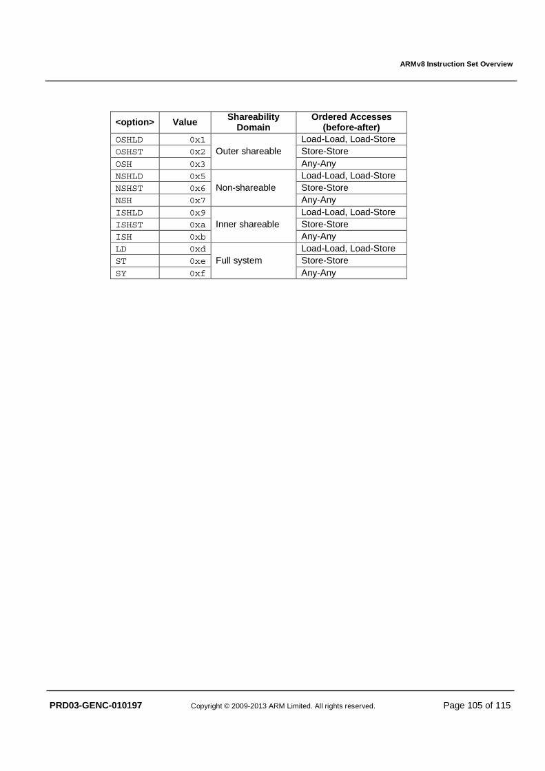
ARMv8 Instruction Set Overview
PRD03-GENC-010197 Copyright © 2009-2013 ARM Limited. All rights reserved. Page 105 of 115
<option> Value Shareability Domain
Ordered Accesses (before-after)
OSHLD 0x1 Load-Load, Load-Store OSHST 0x2 Store-Store OSH 0x3
Outer shareable Any-Any
NSHLD 0x5 Load-Load, Load-Store NSHST 0x6 Store-Store NSH 0x7
Non-shareable Any-Any
ISHLD 0x9 Load-Load, Load-Store ISHST 0xa Store-Store ISH 0xb
Inner shareable Any-Any
LD 0xd Load-Load, Load-Store ST 0xe Store-Store SY 0xf
Full system Any-Any
ARMv8 Instruction Set Overview
PRD03-GENC-010197 Copyright © 2009-2013 ARM Limited. All rights reserved. Page 106 of 115
6 A32 & T32 INSTRUCTION SETS In ARMv8 AArch32 the A32, T32 and T32EE instruction sets are broadly equivalent to the instructions sets named ARM, Thumb and ThumbEE respectively in [v7A]. In addition ARMv8 AArch32 includes A32 and T32 instructions and features introduced by the following ARMv7 architectural extensions:
• Multiprocessing (MP) Extensions. • Large Physical Address Extension (LPAE). • Virtualization Extension (ARMv7VE), regardless of whether exception level EL2 is implemented, including
the SDIV, UDIV, ERET, MRS/MSR (Banked register) and HVC instructions.
• Security Extensions (ARMv6K), regardless of whether exception level EL3 is implemented, including the SMC instruction.
• VFPv4-D32 or VFPv4U-D32, including half-precision floating point, and the VFMA and VFMS instructions.
• Advanced SIMDv2, including half-precision floating point, and the VFMA and VFMS instructions.
The following ARMv7 architectural extensions are substantially altered as part of ARMv8.
• Debug v8 – is backwards compatible in AArch32 state with self-hosted (aka monitor-mode) debug software written for Debug v7.1.
• Optional Performance Monitors Extension (PMUv3) – is backwards compatible in AArch32 state with self-hosted software written for PMUv2.
• Optional Embedded Trace Macrocell (ETMv4) – is not backwards compatible with ETMv3.5 or PFTv1.1. The following are obsoleted in ARMv8:
• A32 SWP and SWPB instructions.
• Jazelle (only trivial implementations are supported). • VFP short vectors and asynchronous bounces. • Fast Context Switch Extension (FCSE).
The following are deprecated in ARMv8 and may be disabled by privileged software:
• A32 and T32 CP15 barriers CP15DSB, CP15ISB and CP15DMB.
• A32 and T32 SETEND instruction.
• A subset of T32 IT instruction functionality, as described in §6.1 below.
• T32EE instructions and coprocessor registers are both deprecated and optional. In addition some of the new functionality provided by the A64 instruction set is independent of the general purpose register width and therefore equally applicable to AArch32 state, namely: enhanced barrier types; hints; load-acquire and store-release; new IEEE 754-2008 operations; and cryptography extensions. Accordingly these new instructions are added to the A32 and T32 instruction sets by ARMv8 as described below. Note that the existing A32 and T32 assembler syntax remains unchanged from ARMv7 UAL. The syntax term <c> where used below represents a standard ARM condition code – mnemonics which do not include <c> may not be conditionally executed.
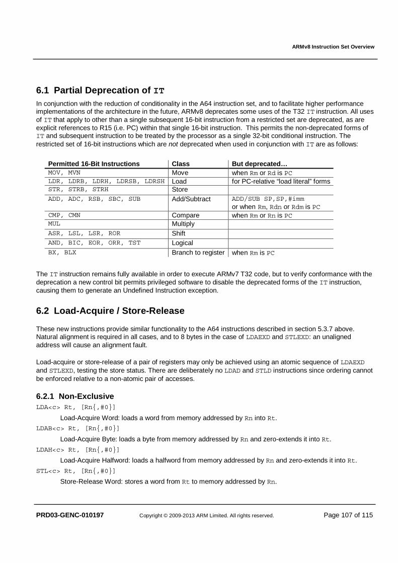
ARMv8 Instruction Set Overview
PRD03-GENC-010197 Copyright © 2009-2013 ARM Limited. All rights reserved. Page 107 of 115
6.1 Partial Deprecation of IT In conjunction with the reduction of conditionality in the A64 instruction set, and to facilitate higher performance implementations of the architecture in the future, ARMv8 deprecates some uses of the T32 IT instruction. All uses of IT that apply to other than a single subsequent 16-bit instruction from a restricted set are deprecated, as are explicit references to R15 (i.e. PC) within that single 16-bit instruction. This permits the non-deprecated forms of IT and subsequent instruction to be treated by the processor as a single 32-bit conditional instruction. The restricted set of 16-bit instructions which are not deprecated when used in conjunction with IT are as follows:
Permitted 16-Bit Instructions Class But deprecated… MOV, MVN Move when Rm or Rd is PC LDR, LDRB, LDRH, LDRSB, LDRSH Load for PC-relative “load literal” forms STR, STRB, STRH Store ADD, ADC, RSB, SBC, SUB Add/Subtract ADD/SUB SP,SP,#imm
or when Rm, Rdn or Rdm is PC CMP, CMN Compare when Rm or Rn is PC MUL Multiply ASR, LSL, LSR, ROR Shift AND, BIC, EOR, ORR, TST Logical BX, BLX Branch to register when Rm is PC
The IT instruction remains fully available in order to execute ARMv7 T32 code, but to verify conformance with the deprecation a new control bit permits privileged software to disable the deprecated forms of the IT instruction, causing them to generate an Undefined Instruction exception.
6.2 Load-Acquire / Store-Release
These new instructions provide similar functionality to the A64 instructions described in section 5.3.7 above. Natural alignment is required in all cases, and to 8 bytes in the case of LDAEXD and STLEXD: an unaligned address will cause an alignment fault.
Load-acquire or store-release of a pair of registers may only be achieved using an atomic sequence of LDAEXD and STLEXD, testing the store status. There are deliberately no LDAD and STLD instructions since ordering cannot be enforced relative to a non-atomic pair of accesses.
6.2.1 Non-Exclusive LDA<c> Rt, [Rn{,#0}]
Load-Acquire Word: loads a word from memory addressed by Rn into Rt.
LDAB<c> Rt, [Rn{,#0}]
Load-Acquire Byte: loads a byte from memory addressed by Rn and zero-extends it into Rt.
LDAH<c> Rt, [Rn{,#0}]
Load-Acquire Halfword: loads a halfword from memory addressed by Rn and zero-extends it into Rt.
STL<c> Rt, [Rn{,#0}]
Store-Release Word: stores a word from Rt to memory addressed by Rn.
ARMv8 Instruction Set Overview
PRD03-GENC-010197 Copyright © 2009-2013 ARM Limited. All rights reserved. Page 108 of 115
STLB<c> Rt, [Rn{,#0}]
Store-Release Byte: stores a byte from Rt to memory addressed by Rn.
STLH<c> Rt, [Rn{,#0}]
Store-Release Halfword: stores a halfword from Rt to memory addressed by Rn.
6.2.2 Exclusive LDAEX<c> Rt, [Rn{,#0}]
Load-Acquire Exclusive Word: loads a word from memory addressed by Rn into Rt. Records the physical address as an exclusive access.
LDAEXB<c> Rt, [Rn{,#0}]
Load-Acquire Exclusive Byte: loads a byte from memory addressed by Rn and zero-extends it into Rt. Records the physical address as an exclusive access.
LDAEXH<c> Rt, [Rn{,#0}]
Load-Acquire Exclusive Halfword: loads a halfword from memory addressed by Rn and zero-extends it into Rt. Records the physical address as an exclusive access.
LDAEXD<c> Rt1, Rt2, [Rn{,#0}]
Load-Acquire Exclusive Double: loads two words from memory addressed by base to Rt1 and Rt2. Records the physical address as an exclusive access. The register Rt1 must be an even-numbered register less than 14 and Rt2 must be R(t1+1).
STLEX<c> Rd, Rt, [Rn{,#0}]
Store-Release Exclusive: stores a word from Rt to memory addressed by Rn, and sets Rd to the returned exclusive access status.
STLEXB<c> Rd, Rt, [Rn{,#0}]
Store-Release Exclusive Byte: stores a byte from Rt to memory addressed by Rn, and sets Rd to the returned exclusive access status.
STLEXH<c> Rd, Rt, [Rn{,#0}]
Store-Release Exclusive Halfword: stores a halfword from Rt to memory addressed by Rn, and sets Rd to the returned exclusive access status.
STLEXD<c> Rd, Rt1, Rt2, [Rn{,#0}]
Store-Release Exclusive Double: stores two words from Rt1 and Rt2 to memory addressed by Rn, and sets Rd to the returned exclusive access status. The register Rt1 must be an even-numbered register less than 14 and Rt2 must be R(t1+1).
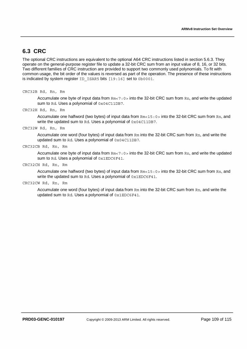
ARMv8 Instruction Set Overview
PRD03-GENC-010197 Copyright © 2009-2013 ARM Limited. All rights reserved. Page 109 of 115
6.3 CRC The optional CRC instructions are equivalent to the optional A64 CRC instructions listed in section 5.6.3. They operate on the general-purpose register file to update a 32-bit CRC sum from an input value of 8, 16, or 32 bits. Two different families of CRC instruction are provided to support two commonly used polynomials. To fit with common usage, the bit order of the values is reversed as part of the operation. The presence of these instructions is indicated by system register ID_ISAR5 bits [19:16] set to 0b0001.
CRC32B Rd, Rn, Rm
Accumulate one byte of input data from Rm<7:0> into the 32-bit CRC sum from Rn, and write the updated sum to Rd. Uses a polynomial of 0x04C11DB7.
CRC32H Rd, Rn, Rm
Accumulate one halfword (two bytes) of input data from Rm<15:0> into the 32-bit CRC sum from Rn, and write the updated sum to Rd. Uses a polynomial of 0x04C11DB7.
CRC32W Rd, Rn, Rm
Accumulate one word (four bytes) of input data from Rm into the 32-bit CRC sum from Rn, and write the updated sum to Rd. Uses a polynomial of 0x04C11DB7.
CRC32CB Rd, Rn, Rm
Accumulate one byte of input data from Rm<7:0> into the 32-bit CRC sum from Rn, and write the updated sum to Rd. Uses a polynomial of 0x1EDC6F41.
CRC32CH Rd, Rn, Rm
Accumulate one halfword (two bytes) of input data from Rm<15:0> into the 32-bit CRC sum from Rn, and write the updated sum to Rd. Uses a polynomial of 0x1EDC6F41.
CRC32CW Rd, Rn, Rm
Accumulate one word (four bytes) of input data from Rm into the 32-bit CRC sum from Rn, and write the updated sum to Rd. Uses a polynomial of 0x1EDC6F41.
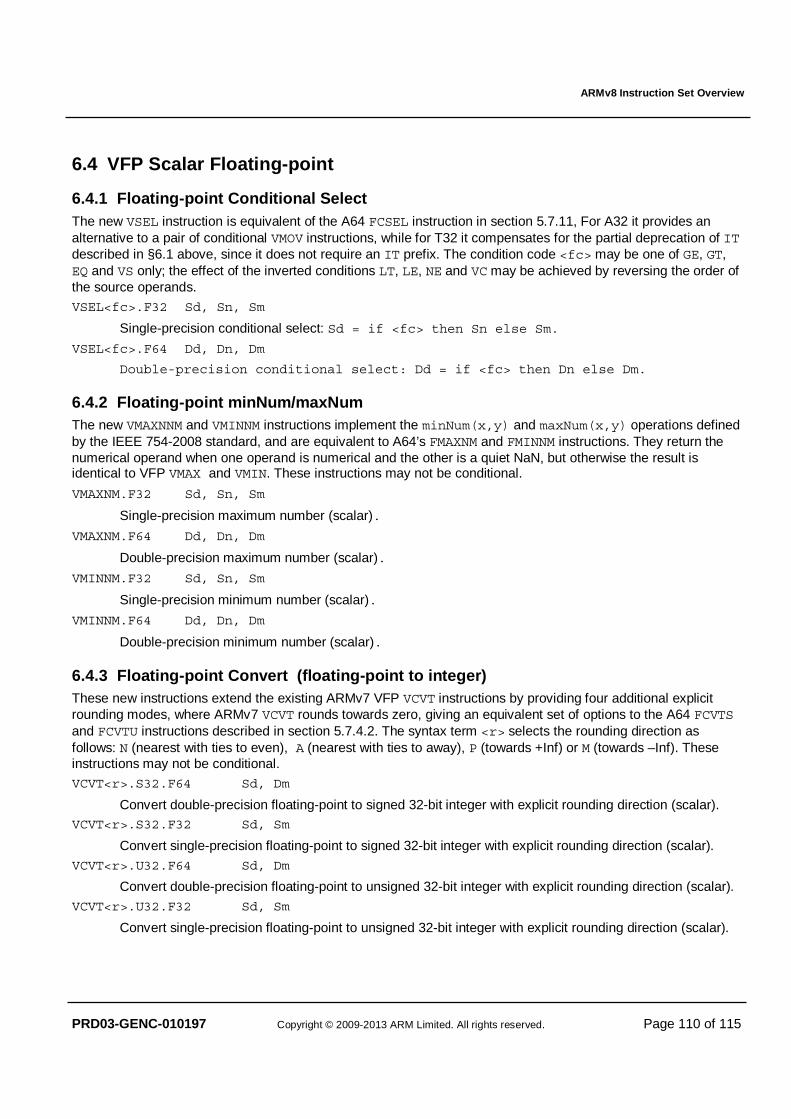
ARMv8 Instruction Set Overview
PRD03-GENC-010197 Copyright © 2009-2013 ARM Limited. All rights reserved. Page 110 of 115
6.4 VFP Scalar Floating-point
6.4.1 Floating-point Conditional Select The new VSEL instruction is equivalent of the A64 FCSEL instruction in section 5.7.11, For A32 it provides an alternative to a pair of conditional VMOV instructions, while for T32 it compensates for the partial deprecation of IT described in §6.1 above, since it does not require an IT prefix. The condition code <fc> may be one of GE, GT, EQ and VS only; the effect of the inverted conditions LT, LE, NE and VC may be achieved by reversing the order of the source operands.
VSEL<fc>.F32 Sd, Sn, Sm
Single-precision conditional select: Sd = if <fc> then Sn else Sm.
VSEL<fc>.F64 Dd, Dn, Dm
Double-precision conditional select: Dd = if <fc> then Dn else Dm.
6.4.2 Floating-point minNum/maxNum The new VMAXNNM and VMINNM instructions implement the minNum(x,y) and maxNum(x,y) operations defined by the IEEE 754-2008 standard, and are equivalent to A64’s FMAXNM and FMINNM instructions. They return the numerical operand when one operand is numerical and the other is a quiet NaN, but otherwise the result is identical to VFP VMAX and VMIN. These instructions may not be conditional.
VMAXNM.F32 Sd, Sn, Sm
Single-precision maximum number (scalar).
VMAXNM.F64 Dd, Dn, Dm
Double-precision maximum number (scalar).
VMINNM.F32 Sd, Sn, Sm
Single-precision minimum number (scalar).
VMINNM.F64 Dd, Dn, Dm
Double-precision minimum number (scalar).
6.4.3 Floating-point Convert (floating-point to integer) These new instructions extend the existing ARMv7 VFP VCVT instructions by providing four additional explicit rounding modes, where ARMv7 VCVT rounds towards zero, giving an equivalent set of options to the A64 FCVTS and FCVTU instructions described in section 5.7.4.2. The syntax term <r> selects the rounding direction as follows: N (nearest with ties to even), A (nearest with ties to away), P (towards +Inf) or M (towards –Inf). These instructions may not be conditional.
VCVT<r>.S32.F64 Sd, Dm
Convert double-precision floating-point to signed 32-bit integer with explicit rounding direction (scalar). VCVT<r>.S32.F32 Sd, Sm
Convert single-precision floating-point to signed 32-bit integer with explicit rounding direction (scalar).
VCVT<r>.U32.F64 Sd, Dm
Convert double-precision floating-point to unsigned 32-bit integer with explicit rounding direction (scalar).
VCVT<r>.U32.F32 Sd, Sm
Convert single-precision floating-point to unsigned 32-bit integer with explicit rounding direction (scalar).
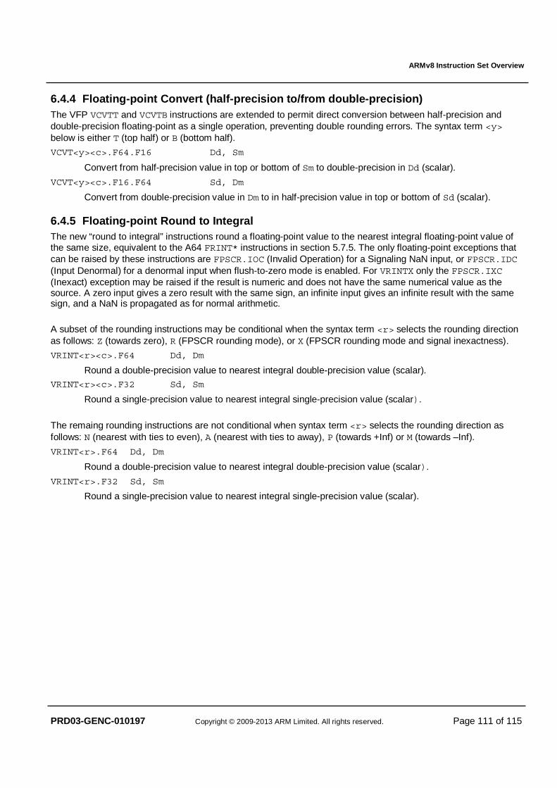
ARMv8 Instruction Set Overview
PRD03-GENC-010197 Copyright © 2009-2013 ARM Limited. All rights reserved. Page 111 of 115
6.4.4 Floating-point Convert (half-precision to/from double-precision) The VFP VCVTT and VCVTB instructions are extended to permit direct conversion between half-precision and double-precision floating-point as a single operation, preventing double rounding errors. The syntax term <y> below is either T (top half) or B (bottom half).
VCVT<y><c>.F64.F16 Dd, Sm
Convert from half-precision value in top or bottom of Sm to double-precision in Dd (scalar).
VCVT<y><c>.F16.F64 Sd, Dm
Convert from double-precision value in Dm to in half-precision value in top or bottom of Sd (scalar).
6.4.5 Floating-point Round to Integral The new “round to integral” instructions round a floating-point value to the nearest integral floating-point value of the same size, equivalent to the A64 FRINT* instructions in section 5.7.5. The only floating-point exceptions that can be raised by these instructions are FPSCR.IOC (Invalid Operation) for a Signaling NaN input, or FPSCR.IDC (Input Denormal) for a denormal input when flush-to-zero mode is enabled. For VRINTX only the FPSCR.IXC (Inexact) exception may be raised if the result is numeric and does not have the same numerical value as the source. A zero input gives a zero result with the same sign, an infinite input gives an infinite result with the same sign, and a NaN is propagated as for normal arithmetic. A subset of the rounding instructions may be conditional when the syntax term <r> selects the rounding direction as follows: Z (towards zero), R (FPSCR rounding mode), or X (FPSCR rounding mode and signal inexactness).
VRINT<r><c>.F64 Dd, Dm
Round a double-precision value to nearest integral double-precision value (scalar).
VRINT<r><c>.F32 Sd, Sm
Round a single-precision value to nearest integral single-precision value (scalar). The remaing rounding instructions are not conditional when syntax term <r> selects the rounding direction as follows: N (nearest with ties to even), A (nearest with ties to away), P (towards +Inf) or M (towards –Inf).
VRINT<r>.F64 Dd, Dm
Round a double-precision value to nearest integral double-precision value (scalar).
VRINT<r>.F32 Sd, Sm
Round a single-precision value to nearest integral single-precision value (scalar).
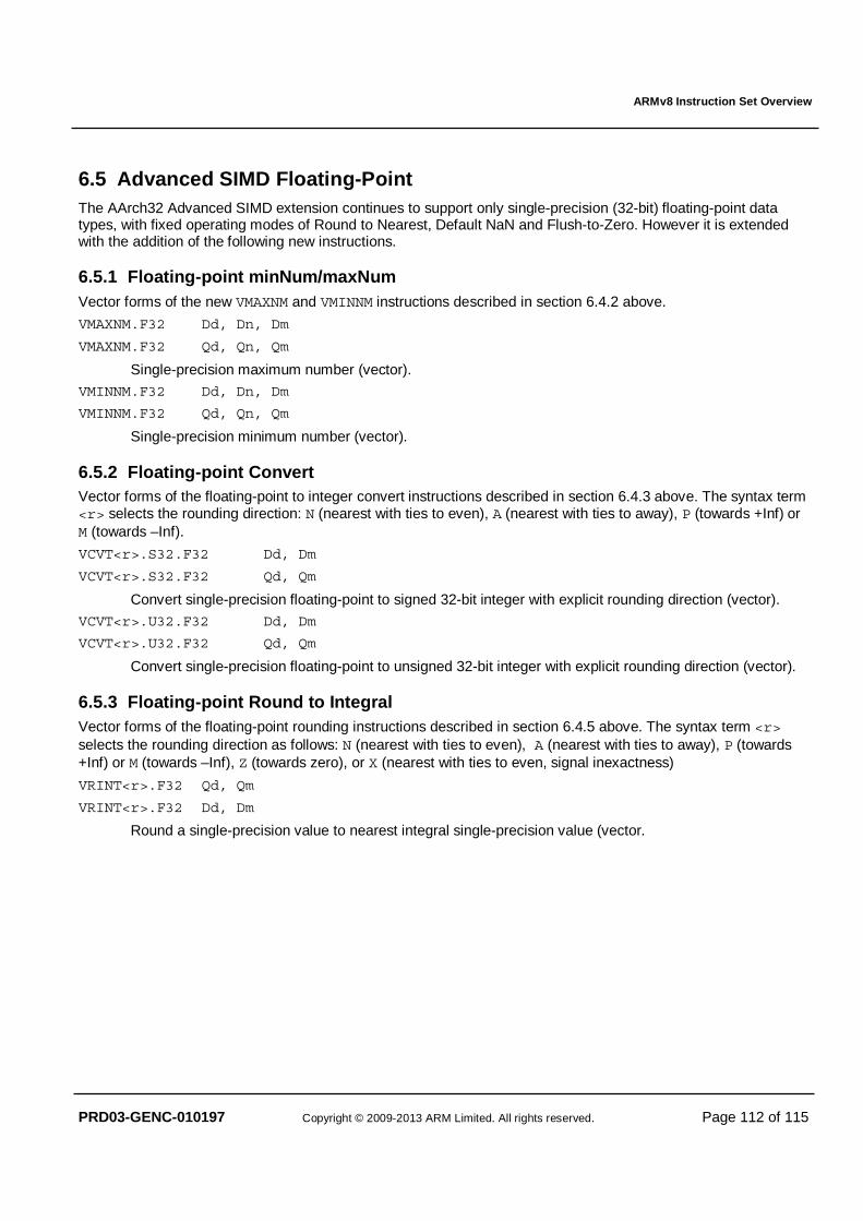
ARMv8 Instruction Set Overview
PRD03-GENC-010197 Copyright © 2009-2013 ARM Limited. All rights reserved. Page 112 of 115
6.5 Advanced SIMD Floating-Point The AArch32 Advanced SIMD extension continues to support only single-precision (32-bit) floating-point data types, with fixed operating modes of Round to Nearest, Default NaN and Flush-to-Zero. However it is extended with the addition of the following new instructions.
6.5.1 Floating-point minNum/maxNum Vector forms of the new VMAXNM and VMINNM instructions described in section 6.4.2 above.
VMAXNM.F32 Dd, Dn, Dm
VMAXNM.F32 Qd, Qn, Qm
Single-precision maximum number (vector).
VMINNM.F32 Dd, Dn, Dm
VMINNM.F32 Qd, Qn, Qm
Single-precision minimum number (vector).
6.5.2 Floating-point Convert Vector forms of the floating-point to integer convert instructions described in section 6.4.3 above. The syntax term <r> selects the rounding direction: N (nearest with ties to even), A (nearest with ties to away), P (towards +Inf) or M (towards –Inf).
VCVT<r>.S32.F32 Dd, Dm
VCVT<r>.S32.F32 Qd, Qm
Convert single-precision floating-point to signed 32-bit integer with explicit rounding direction (vector).
VCVT<r>.U32.F32 Dd, Dm
VCVT<r>.U32.F32 Qd, Qm
Convert single-precision floating-point to unsigned 32-bit integer with explicit rounding direction (vector).
6.5.3 Floating-point Round to Integral Vector forms of the floating-point rounding instructions described in section 6.4.5 above. The syntax term <r> selects the rounding direction as follows: N (nearest with ties to even), A (nearest with ties to away), P (towards +Inf) or M (towards –Inf), Z (towards zero), or X (nearest with ties to even, signal inexactness)
VRINT<r>.F32 Qd, Qm
VRINT<r>.F32 Dd, Dm
Round a single-precision value to nearest integral single-precision value (vector.
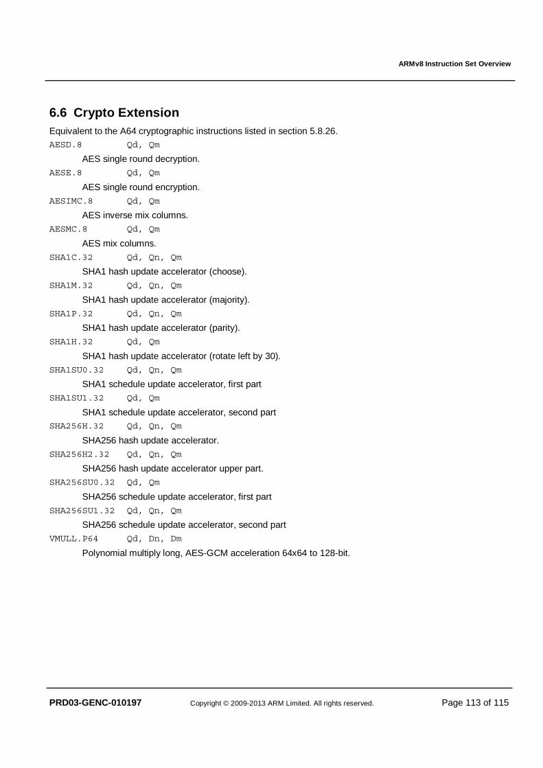
ARMv8 Instruction Set Overview
PRD03-GENC-010197 Copyright © 2009-2013 ARM Limited. All rights reserved. Page 113 of 115
6.6 Crypto Extension Equivalent to the A64 cryptographic instructions listed in section 5.8.26. AESD.8 Qd, Qm
AES single round decryption.
AESE.8 Qd, Qm
AES single round encryption.
AESIMC.8 Qd, Qm
AES inverse mix columns.
AESMC.8 Qd, Qm
AES mix columns.
SHA1C.32 Qd, Qn, Qm
SHA1 hash update accelerator (choose).
SHA1M.32 Qd, Qn, Qm
SHA1 hash update accelerator (majority).
SHA1P.32 Qd, Qn, Qm
SHA1 hash update accelerator (parity).
SHA1H.32 Qd, Qm
SHA1 hash update accelerator (rotate left by 30).
SHA1SU0.32 Qd, Qn, Qm
SHA1 schedule update accelerator, first part
SHA1SU1.32 Qd, Qm
SHA1 schedule update accelerator, second part SHA256H.32 Qd, Qn, Qm
SHA256 hash update accelerator.
SHA256H2.32 Qd, Qn, Qm
SHA256 hash update accelerator upper part.
SHA256SU0.32 Qd, Qm
SHA256 schedule update accelerator, first part
SHA256SU1.32 Qd, Qn, Qm
SHA256 schedule update accelerator, second part
VMULL.P64 Qd, Dn, Dm
Polynomial multiply long, AES-GCM acceleration 64x64 to 128-bit.
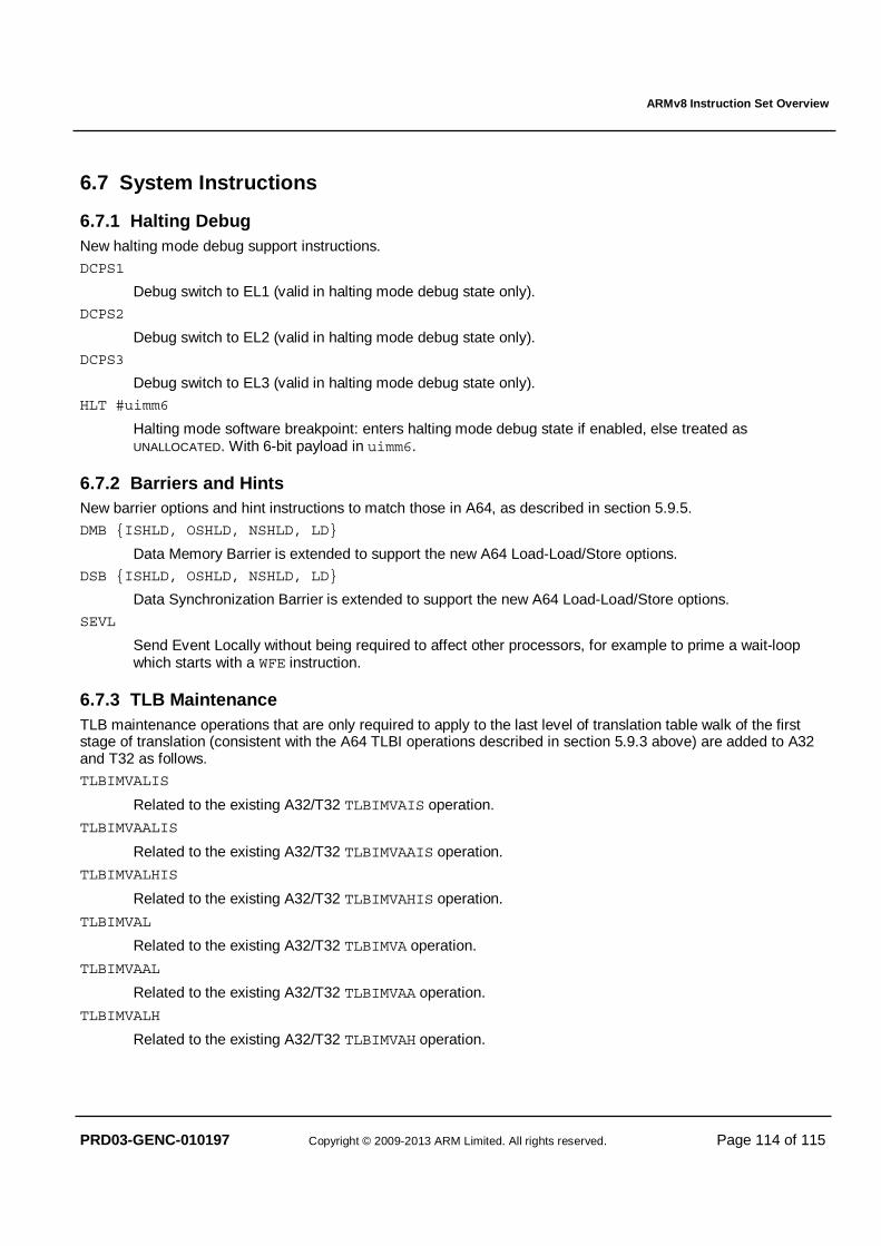
ARMv8 Instruction Set Overview
PRD03-GENC-010197 Copyright © 2009-2013 ARM Limited. All rights reserved. Page 114 of 115
6.7 System Instructions
6.7.1 Halting Debug New halting mode debug support instructions.
DCPS1
Debug switch to EL1 (valid in halting mode debug state only).
DCPS2
Debug switch to EL2 (valid in halting mode debug state only).
DCPS3
Debug switch to EL3 (valid in halting mode debug state only).
HLT #uimm6
Halting mode software breakpoint: enters halting mode debug state if enabled, else treated as UNALLOCATED. With 6-bit payload in uimm6.
6.7.2 Barriers and Hints New barrier options and hint instructions to match those in A64, as described in section 5.9.5.
DMB {ISHLD, OSHLD, NSHLD, LD}
Data Memory Barrier is extended to support the new A64 Load-Load/Store options.
DSB {ISHLD, OSHLD, NSHLD, LD}
Data Synchronization Barrier is extended to support the new A64 Load-Load/Store options.
SEVL
Send Event Locally without being required to affect other processors, for example to prime a wait-loop which starts with a WFE instruction.
6.7.3 TLB Maintenance TLB maintenance operations that are only required to apply to the last level of translation table walk of the first stage of translation (consistent with the A64 TLBI operations described in section 5.9.3 above) are added to A32 and T32 as follows.
TLBIMVALIS
Related to the existing A32/T32 TLBIMVAIS operation.
TLBIMVAALIS
Related to the existing A32/T32 TLBIMVAAIS operation.
TLBIMVALHIS
Related to the existing A32/T32 TLBIMVAHIS operation.
TLBIMVAL
Related to the existing A32/T32 TLBIMVA operation.
TLBIMVAAL
Related to the existing A32/T32 TLBIMVAA operation.
TLBIMVALH
Related to the existing A32/T32 TLBIMVAH operation.
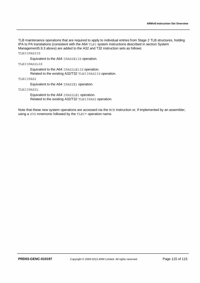
ARMv8 Instruction Set Overview
PRD03-GENC-010197 Copyright © 2009-2013 ARM Limited. All rights reserved. Page 115 of 115
TLB maintenance operations that are required to apply to individual entries from Stage 2 TLB structures, holding IPA to PA translations (consistent with the A64 TLBI system instructions described in section System Management5.9.3 above) are added to the A32 and T32 instruction sets as follows: TLBIIPAS2IS
Equivalent to the A64 IPAS2E1IS operation.
TLBIIPAS2LIS
Equivalent to the A64 IPAS2LE1IS operation. Related to the existing A32/T32 TLBIIPAS2IS operation.
TLBIIPAS2
Equivalent to the A64 IPAS2E1 operation.
TLBIIPAS2L
Equivalent to the A64 IPAS2LE1 operation. Related to the existing A32/T32 TLBIIPAS2 operation.
Note that these new system operations are accessed via the MCR instruction or, if implemented by an assembler, using a SYS mnemonic followed by the TLBI* operation name.