Embed Size (px)
Citation preview
Document
ARROW ARIS EDGE Board – User’s Guide 27/09/2017
Doc: R16P10DTUG00, Rev: 1.3 1 of 21
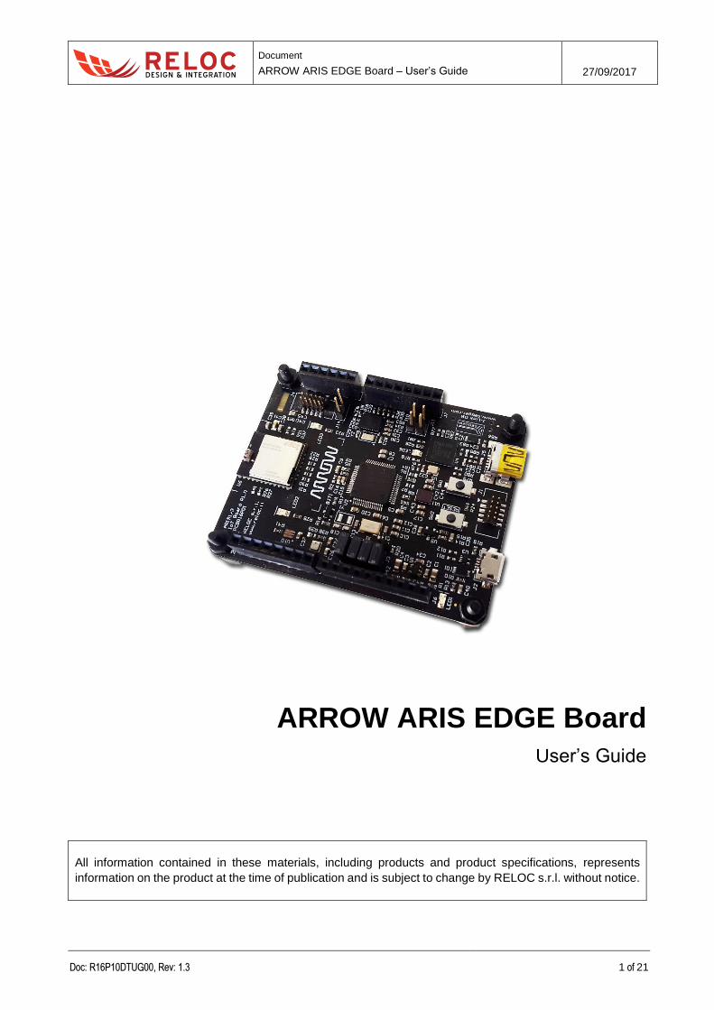
ARROW ARIS EDGE Board
User’s Guide
All information contained in these materials, including products and product specifications, represents
information on the product at the time of publication and is subject to change by RELOC s.r.l. without notice.
Document
ARROW ARIS EDGE Board – User’s Guide 27/09/2017
Doc: R16P10DTUG00, Rev: 1.3 2 of 21
Outline
1. Introduction .............................................................................................................................. 4
1.1. Description ........................................................................................................................ 4
1.2. Kit contents ....................................................................................................................... 4
2. System overview ...................................................................................................................... 5
2.1. Board main features .......................................................................................................... 5
2.2. Block diagram ................................................................................................................... 6
3. Getting started ......................................................................................................................... 7
3.1. ARIS EDGE pre-programmed demo.................................................................................. 7
3.2. Creating and debugging a sample “Blinky” project............................................................. 8
3.2.1 Prerequisites ............................................................................................................ 8
3.2.2 ARIS EDGE BSP ..................................................................................................... 8
3.2.3 Creating and building a demo project ....................................................................... 9
3.2.4 Board configuration and connection ....................................................................... 11
3.2.5 Debugging the project ............................................................................................ 11
3.3. Flashing a new firmware on MGM111 multi-protocol radio module .................................. 11
4. Connectors ............................................................................................................................ 13
4.1. Arduino expansion connector .......................................................................................... 15
4.2. JTAG connectors............................................................................................................. 16
4.3. USB device ..................................................................................................................... 16
5. Usage .................................................................................................................................... 17
5.1. Power supply ................................................................................................................... 17
5.2. Power enable and measurement ..................................................................................... 18
5.3. Push buttons, LEDs and buzzer ...................................................................................... 18
6. Board layout........................................................................................................................... 21
Document
ARROW ARIS EDGE Board – User’s Guide 27/09/2017
Doc: R16P10DTUG00, Rev: 1.3 3 of 21
Revisions
REVISION DATE DESCRIPTION STATUS AUTHOR REVISER
0.1 10/01/2017 Document created draft L. Dal Bello
1.0 20/01/2017 Document released release L. Dal Bello C. Tagliaferri
1.1 08/03/2017 Hardware description revised
Minor software updates release C. Tagliaferri A. Ricci
1.2 05/05/2017 ARIS EDGE production release updates release C. Tagliaferri A. Ricci
1.3 27/09/2017
Supersede previous HW and SW user’s
guides
Flashing guide added
Minor improvements introduced
release L. Dal Bello A. Ricci
Disclaimer
All rights strictly reserved. Reproduction in any form is not permitted without written authorization from
RELOC s.r.l.
RELOC s.r.l.
HEADQUARTERS
Via Borsari, 23/A 43126 – Parma (Italy)
Phone +39-0521-1759942
www.reloc.it
Document
ARROW ARIS EDGE Board – User’s Guide 27/09/2017
Doc: R16P10DTUG00, Rev: 1.3 4 of 21
1. Introduction
1.1. Description
ARIS EDGE board, developed by RELOC for Arrow Electronics, is a ready-to-use Internet of Things
(IoT) hardware and software platform that enables users to get their IoT applications up and running
quickly, exploiting the Renesas Synergy development framework.
Based on Renesas Synergy S1 MCU with a 32-MHz ARM Cortex-M0+ core, the ARIS EDGE board
has a host of features that equip it for smart sensing and IoT operations. Communication with other
devices and the cloud is enabled by means of a flexible multi-protocol radio module, supporting
Bluetooth Low Energy, Thread and ZigBee stacks. Board sensing capabilities include motion
detection via 9-degrees-of-freedom IMU with sensor fusion capabilities, environmental temperature,
humidity, pressure and ambient light sampling.
The Renesas Synergy Platform helps to accelerate IoT designs: a proven combination of hardware
and software makes development easier and faster, thus encouraging innovation and product
differentiation. The combination of Arrow ARIS board and Renesas Synergy software platform
enables developers to reduce time–to–market and decreases the total cost of ownership of a product
over its lifetime.
1.2. Kit contents
The following items are included in the box:
1x ARIS EDGE board
1x USB type A-male to mini-B-male cable
Document
ARROW ARIS EDGE Board – User’s Guide 27/09/2017
Doc: R16P10DTUG00, Rev: 1.3 5 of 21
2. System overview
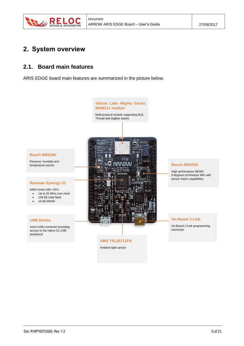
2.1. Board main features
ARIS EDGE board main features are summarized in the picture below.
Silicon Labs Mighty Gecko
MGM111 module
Multi-protocol module supporting BLE,
Thread and ZigBee stacks
Renesas Synergy S1
ARM Cortex-M0+ CPU
Up to 32-MHz core clock
128 kB code flash
16 kB SRAM
Bosch BNO055
High performance MEMS
9-degrees-of-freedom IMU with
sensor fusion capabilities
Bosch BME280
Pressure, humidity and
temperature sensor
AMS TSL25711FN
Ambient light sensor
USB Device
micro-USB connector providing
access to the native S1 USB
peripheral
On-Board J-Link
On-Board J-Link programming
connector
Document
ARROW ARIS EDGE Board – User’s Guide 27/09/2017
Doc: R16P10DTUG00, Rev: 1.3 6 of 21
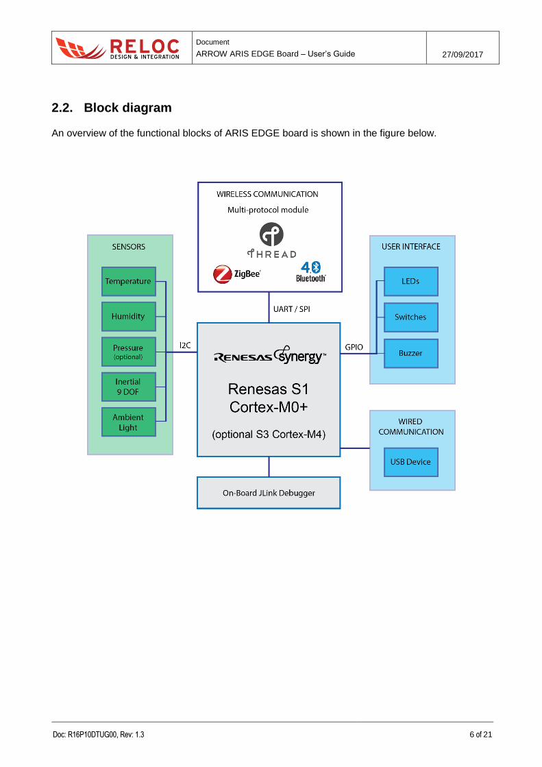
2.2. Block diagram
An overview of the functional blocks of ARIS EDGE board is shown in the figure below.
Document
ARROW ARIS EDGE Board – User’s Guide 27/09/2017
Doc: R16P10DTUG00, Rev: 1.3 7 of 21
3. Getting started
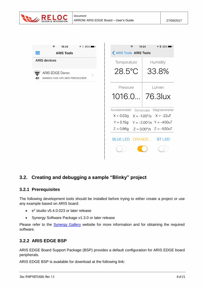
3.1. ARIS EDGE pre-programmed demo
The ARIS EDGE board is pre-programmed with a demo application which continuously monitors the
on-board sensors and sends collected data on Bluetooth Low-Energy (BLE) network.
The Synergy S1 device takes care of sampling sensors data whereas the MGM111 multi-protocol
module establishes the BLE communication with a BLE client.
Additional information about the internal demo software behavior can be found in “BLE Sensors
demo” document.
In order to test ARIS EDGE functionalities by means of pre-programmed demo application
1. download the free ARIS Tools smartphone App from
a. Apple App StoreTM ( https://itunes.apple.com/us/app/aris-tools/id1161792783 ) or
b. Google PlayTM ( https://play.google.com/store/apps/details?id=com.demo.rlc.arisapp );
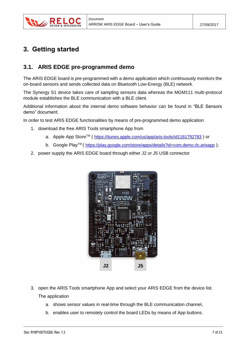
2. power supply the ARIS EDGE board through either J2 or J5 USB connector
3. open the ARIS Tools smartphone App and select your ARIS EDGE from the device list.
The application
a. shows sensor values in real-time through the BLE communication channel,
b. enables user to remotely control the board LEDs by means of App buttons.
J5 J2
Document
ARROW ARIS EDGE Board – User’s Guide 27/09/2017
Doc: R16P10DTUG00, Rev: 1.3 8 of 21
3.2. Creating and debugging a sample “Blinky” project
3.2.1 Prerequisites
The following development tools should be installed before trying to either create a project or use
any example based on ARIS board:
e2 studio v5.4.0.023 or later release
Synergy Software Package v1.3.0 or later release
Please refer to the Synergy Gallery website for more information and for obtaining the required
software.
3.2.2 ARIS EDGE BSP
ARIS EDGE Board Support Package (BSP) provides a default configuration for ARIS EDGE board
peripherals.
ARIS EDGE BSP is available for download at the following link:
Document
ARROW ARIS EDGE Board – User’s Guide 27/09/2017
Doc: R16P10DTUG00, Rev: 1.3 9 of 21
http://www.reloc.it/download/products/ARIS-EDGE/reloc.aris_edge1.1.3.0.zip
In order to install it, please unzip the archive and copy the file “Reloc.Aris_Edge1.1.3.0.pack” in the
following directory:
%e2_studio_install_dir%\internal\projectgen\arm\Packs
where
%e2_studio_install_dir% is typically the folder “C:\Renesas\e2_studio\”
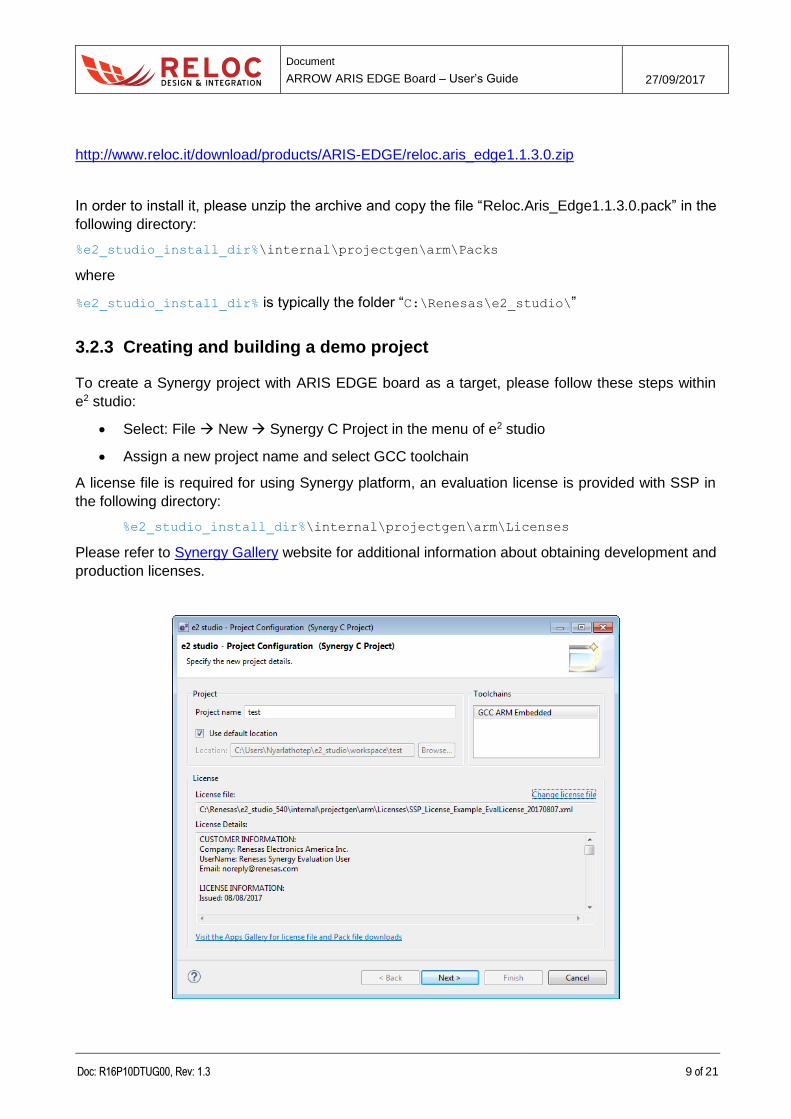
3.2.3 Creating and building a demo project
To create a Synergy project with ARIS EDGE board as a target, please follow these steps within
e2 studio:
Select: File New Synergy C Project in the menu of e2 studio
Assign a new project name and select GCC toolchain
A license file is required for using Synergy platform, an evaluation license is provided with SSP in
the following directory:
%e2_studio_install_dir%\internal\projectgen\arm\Licenses
Please refer to Synergy Gallery website for additional information about obtaining development and
production licenses.
Document
ARROW ARIS EDGE Board – User’s Guide 27/09/2017
Doc: R16P10DTUG00, Rev: 1.3 10 of 21
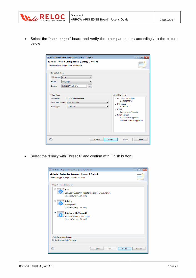
Select the “aris_edge1” board and verify the other parameters accordingly to the picture
below
Select the “Blinky with ThreadX” and confirm with Finish button:
Document
ARROW ARIS EDGE Board – User’s Guide 27/09/2017
Doc: R16P10DTUG00, Rev: 1.3 11 of 21
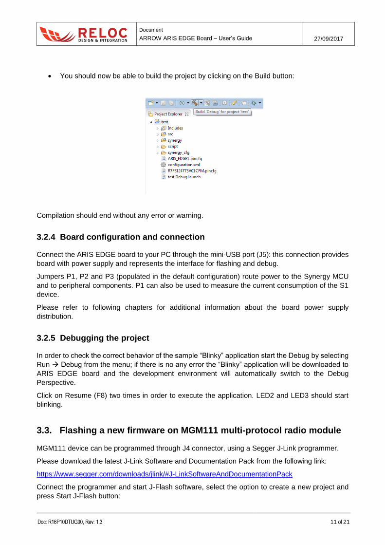
You should now be able to build the project by clicking on the Build button:
Compilation should end without any error or warning.
3.2.4 Board configuration and connection
Connect the ARIS EDGE board to your PC through the mini-USB port (J5): this connection provides
board with power supply and represents the interface for flashing and debug.
Jumpers P1, P2 and P3 (populated in the default configuration) route power to the Synergy MCU
and to peripheral components. P1 can also be used to measure the current consumption of the S1
device.
Please refer to following chapters for additional information about the board power supply
distribution.
3.2.5 Debugging the project
In order to check the correct behavior of the sample “Blinky” application start the Debug by selecting
Run Debug from the menu; if there is no any error the “Blinky” application will be downloaded to
ARIS EDGE board and the development environment will automatically switch to the Debug
Perspective.
Click on Resume (F8) two times in order to execute the application. LED2 and LED3 should start
blinking.
3.3. Flashing a new firmware on MGM111 multi-protocol radio module
MGM111 device can be programmed through J4 connector, using a Segger J-Link programmer.
Please download the latest J-Link Software and Documentation Pack from the following link:
https://www.segger.com/downloads/jlink/#J-LinkSoftwareAndDocumentationPack
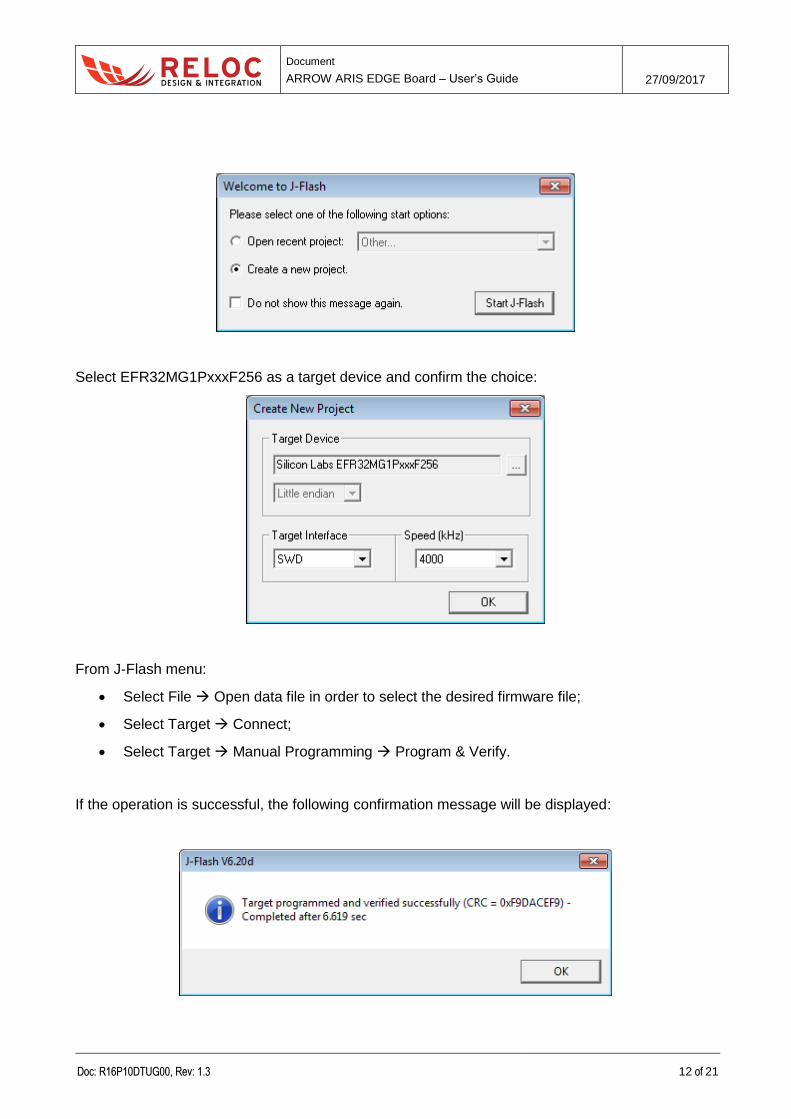
Connect the programmer and start J-Flash software, select the option to create a new project and
press Start J-Flash button:
Document
ARROW ARIS EDGE Board – User’s Guide 27/09/2017
Doc: R16P10DTUG00, Rev: 1.3 12 of 21
Select EFR32MG1PxxxF256 as a target device and confirm the choice:
From J-Flash menu:
Select File Open data file in order to select the desired firmware file;
Select Target Connect;
Select Target Manual Programming Program & Verify.
If the operation is successful, the following confirmation message will be displayed:
Document
ARROW ARIS EDGE Board – User’s Guide 27/09/2017
Doc: R16P10DTUG00, Rev: 1.3 13 of 21
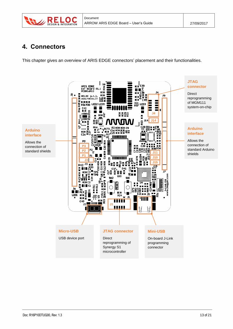
4. Connectors
This chapter gives an overview of ARIS EDGE connectors’ placement and their functionalities.
JTAG
connector
Direct
reprogramming
of MGM111
system-on-chip
Arduino
interface
Allows the
connection of
standard Arduino
shields
J14
J11 J10 J15
P3 P2 P1
J3
Mini-USB
On-board J-Link
programming
connector
Micro-USB
USB device port
JTAG connector
Direct
reprogramming of
Synergy S1
microcontroller
Arduino
interface
Allows the
connection of
standard shields
J4
J1
Document
ARROW ARIS EDGE Board – User’s Guide 27/09/2017
Doc: R16P10DTUG00, Rev: 1.3 14 of 21
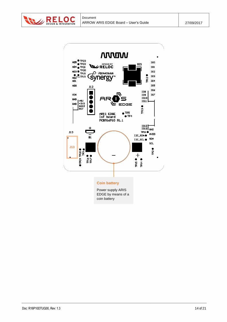
Coin battery
Power supply ARIS
EDGE by means of a
coin battery
J13
Document
ARROW ARIS EDGE Board – User’s Guide 27/09/2017
Doc: R16P10DTUG00, Rev: 1.3 15 of 21
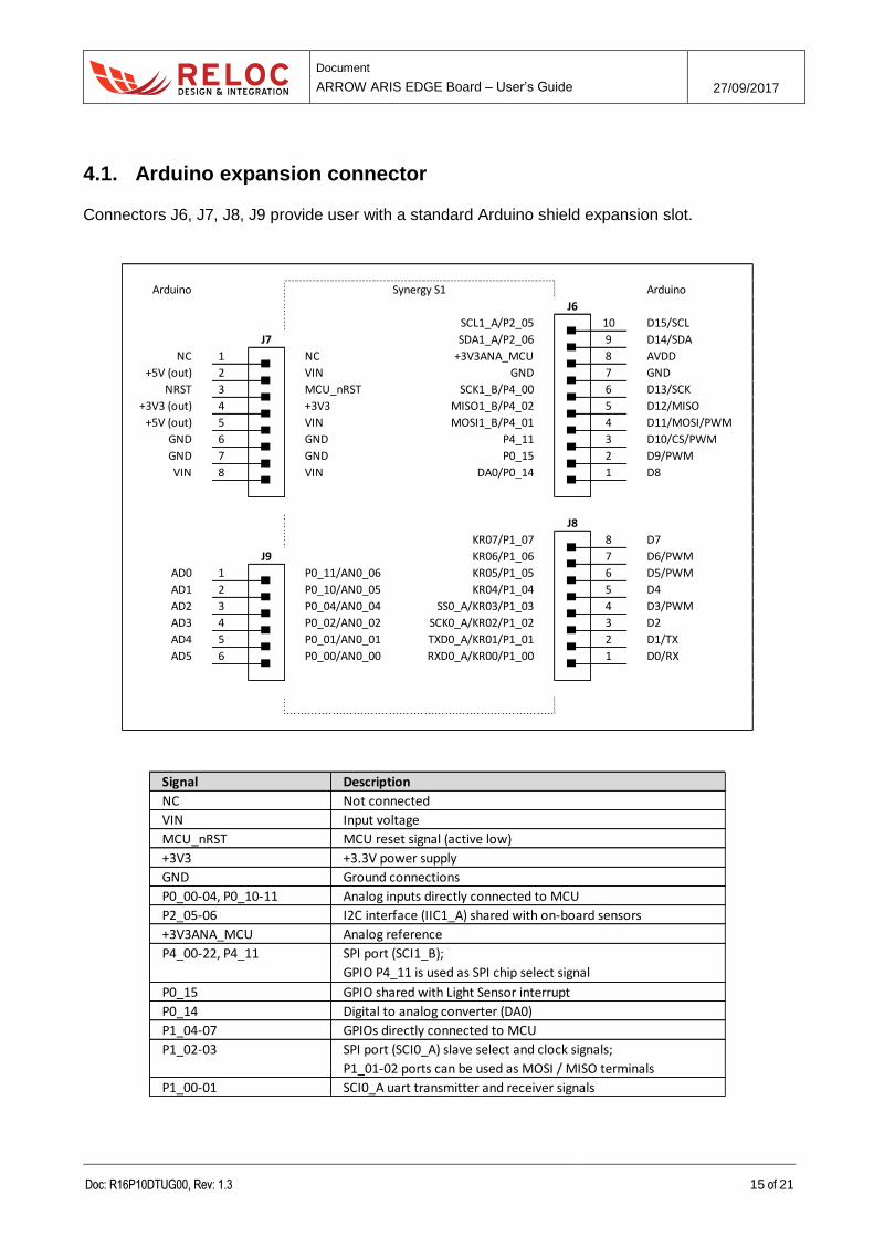
4.1. Arduino expansion connector
Connectors J6, J7, J8, J9 provide user with a standard Arduino shield expansion slot.
Arduino Synergy S1 Arduino
SCL1_A/P2_05 D15/SCL
SDA1_A/P2_06 D14/SDA
NC 1 NC +3V3ANA_MCU AVDD
+5V (out) 2 VIN GND GND
NRST 3 MCU_nRST SCK1_B/P4_00 D13/SCK
+3V3 (out) 4 +3V3 MISO1_B/P4_02 D12/MISO
+5V (out) 5 VIN MOSI1_B/P4_01 D11/MOSI/PWM
GND 6 GND P4_11 D10/CS/PWM
GND 7 GND P0_15 D9/PWM
VIN 8 VIN DA0/P0_14 D8
KR07/P1_07 D7
KR06/P1_06 D6/PWM
AD0 1 P0_11/AN0_06 KR05/P1_05 D5/PWM
AD1 2 P0_10/AN0_05 KR04/P1_04 D4
AD2 3 P0_04/AN0_04 SS0_A/KR03/P1_03 D3/PWM
AD3 4 P0_02/AN0_02 SCK0_A/KR02/P1_02 D2
AD4 5 P0_01/AN0_01 TXD0_A/KR01/P1_01 D1/TX
AD5 6 P0_00/AN0_00 RXD0_A/KR00/P1_00 D0/RX
2
1
4
3
J6
J7
5
8
7
6
2
5
4
3
8
7
J9
10
9
J8
6
1
Signal Description
NC Not connected
VIN Input voltage
MCU_nRST MCU reset signal (active low)
+3V3 +3.3V power supply
GND Ground connections
P0_00-04, P0_10-11 Analog inputs directly connected to MCU
P2_05-06 I2C interface (IIC1_A) shared with on-board sensors
+3V3ANA_MCU Analog reference
P0_15 GPIO shared with Light Sensor interrupt
P0_14 Digital to analog converter (DA0)
P1_04-07 GPIOs directly connected to MCU
P1_00-01 SCI0_A uart transmitter and receiver signals
SPI port (SCI1_B);
GPIO P4_11 is used as SPI chip select signal
P4_00-22, P4_11
SPI port (SCI0_A) slave select and clock signals;
P1_01-02 ports can be used as MOSI / MISO terminals
P1_02-03
Document
ARROW ARIS EDGE Board – User’s Guide 27/09/2017
Doc: R16P10DTUG00, Rev: 1.3 16 of 21
4.2. JTAG connectors
The ARIS EDGE development kit features an on-board SEGGER J-Link debugger (see J5 mini-USB
port), which can be used to program and debug the Synergy S1 microcontroller.
The ARIS EDGE board includes additional JTAG connectors, detailed below for reference:
J1 – JTAG connector which can be used to program and debug Synergy S1 with an external
J-Link debugger;
J4 – JTAG connector routed to the Silicon Labs Mighty Gecko system-on-chip (MGM111
module);
J13 – E1 programmer connector routed to the Renesas RX621 chip. Such a chip provides
users with the on-board SEGGER J-Link facility, thus it should not be erased and/or re-
programmed.
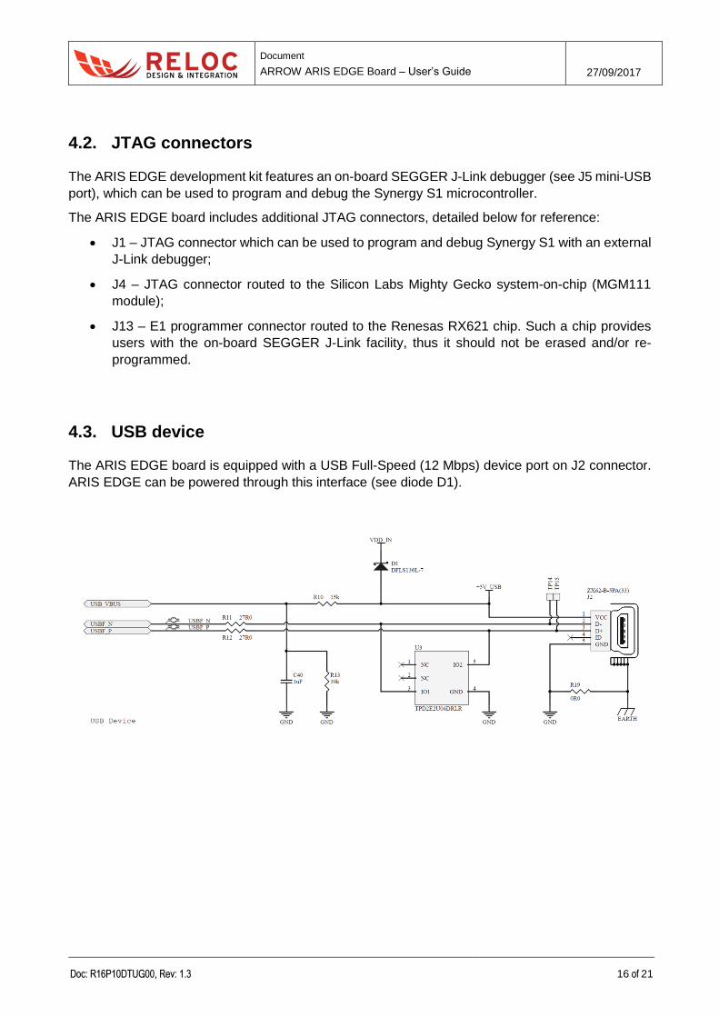
4.3. USB device
The ARIS EDGE board is equipped with a USB Full-Speed (12 Mbps) device port on J2 connector.
ARIS EDGE can be powered through this interface (see diode D1).
Document
ARROW ARIS EDGE Board – User’s Guide 27/09/2017
Doc: R16P10DTUG00, Rev: 1.3 17 of 21
5. Usage
This chapter describes how to connect, configure and interact with the ARIS EDGE board.
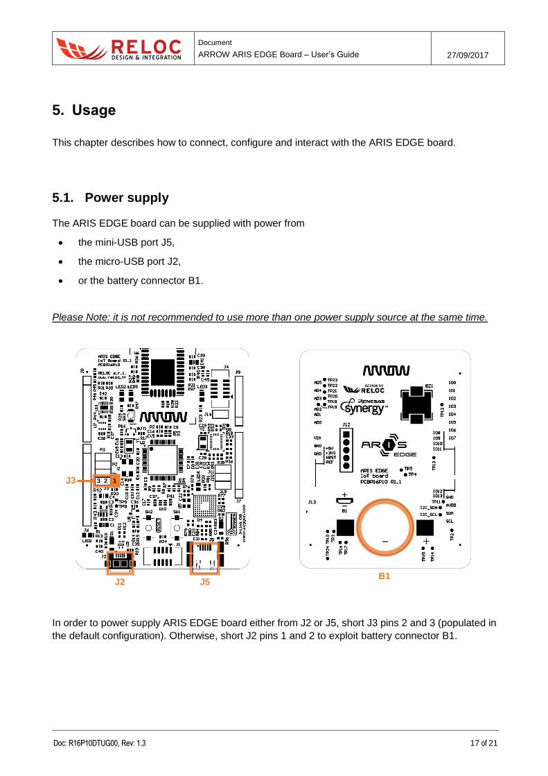
5.1. Power supply
The ARIS EDGE board can be supplied with power from
the mini-USB port J5,
the micro-USB port J2,
or the battery connector B1.
Please Note: it is not recommended to use more than one power supply source at the same time.
In order to power supply ARIS EDGE board either from J2 or J5, short J3 pins 2 and 3 (populated in
the default configuration). Otherwise, short J2 pins 1 and 2 to exploit battery connector B1.
J2 J5 B1
3 2 1 J3

Document
ARROW ARIS EDGE Board – User’s Guide 27/09/2017
Doc: R16P10DTUG00, Rev: 1.3 18 of 21
5.2. Power enable and measurement
P1, P2 and P3 (populated in the default configuration) provide power to the Synergy S1 MCU,
sensors and radio module, respectively (i.e. connect the input power sources to the board loads).
They can also be used to measure the current consumption of the ARIS EDGE circuitry sections.
J10 and J11 (not populated in the default configuration) could be used to provide power to the
Arduino connectors; before placing a jumper please check that current consumption of the shield is
within maximum values provided by the +5V input and +3.3V regulated power supply.
5.3. Push buttons, LEDs and buzzer
ARIS EDGE developer is provided with a basic user interface, including buttons, LEDs and buzzer.
Document
ARROW ARIS EDGE Board – User’s Guide 27/09/2017
Doc: R16P10DTUG00, Rev: 1.3 19 of 21
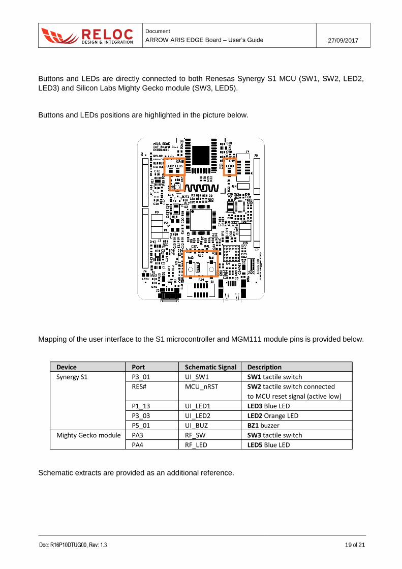
Buttons and LEDs are directly connected to both Renesas Synergy S1 MCU (SW1, SW2, LED2,
LED3) and Silicon Labs Mighty Gecko module (SW3, LED5).
Buttons and LEDs positions are highlighted in the picture below.
Mapping of the user interface to the S1 microcontroller and MGM111 module pins is provided below.
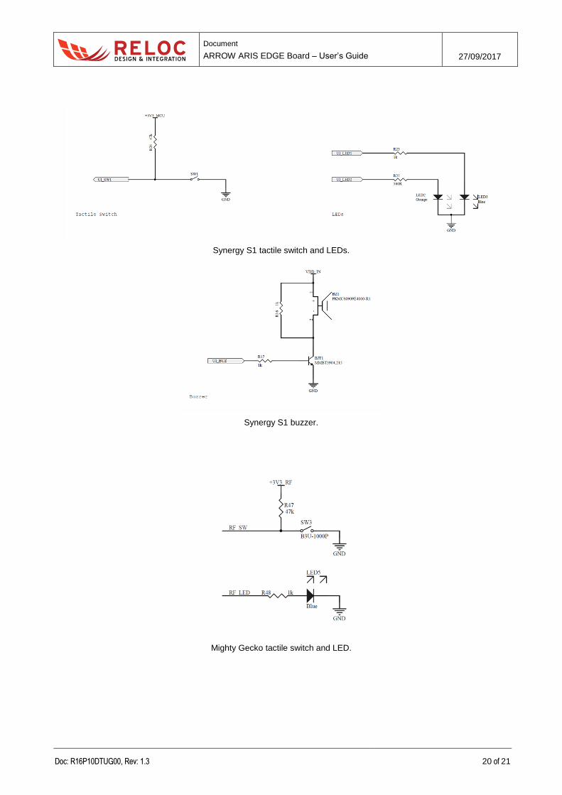
Schematic extracts are provided as an additional reference.
Device Port Schematic Signal Description
P3_01 UI_SW1 SW1 tactile switch
RES# MCU_nRST SW2 tactile switch connected
to MCU reset signal (active low)
P1_13 UI_LED1 LED3 Blue LED
P3_03 UI_LED2 LED2 Orange LED
P5_01 UI_BUZ BZ1 buzzer
PA3 RF_SW SW3 tactile switch
PA4 RF_LED LED5 Blue LED
Mighty Gecko module
Synergy S1
Document
ARROW ARIS EDGE Board – User’s Guide 27/09/2017
Doc: R16P10DTUG00, Rev: 1.3 20 of 21
Synergy S1 tactile switch and LEDs.
Synergy S1 buzzer.
Mighty Gecko tactile switch and LED.
Document
ARROW ARIS EDGE Board – User’s Guide 27/09/2017
Doc: R16P10DTUG00, Rev: 1.3 21 of 21
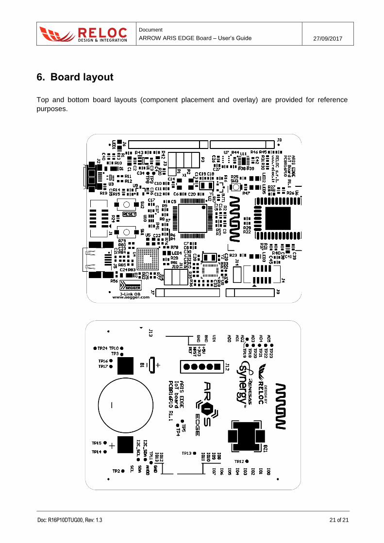
6. Board layout
Top and bottom board layouts (component placement and overlay) are provided for reference
purposes.