Embed Size (px)
DESCRIPTION
Piping for Process Plants
Citation preview
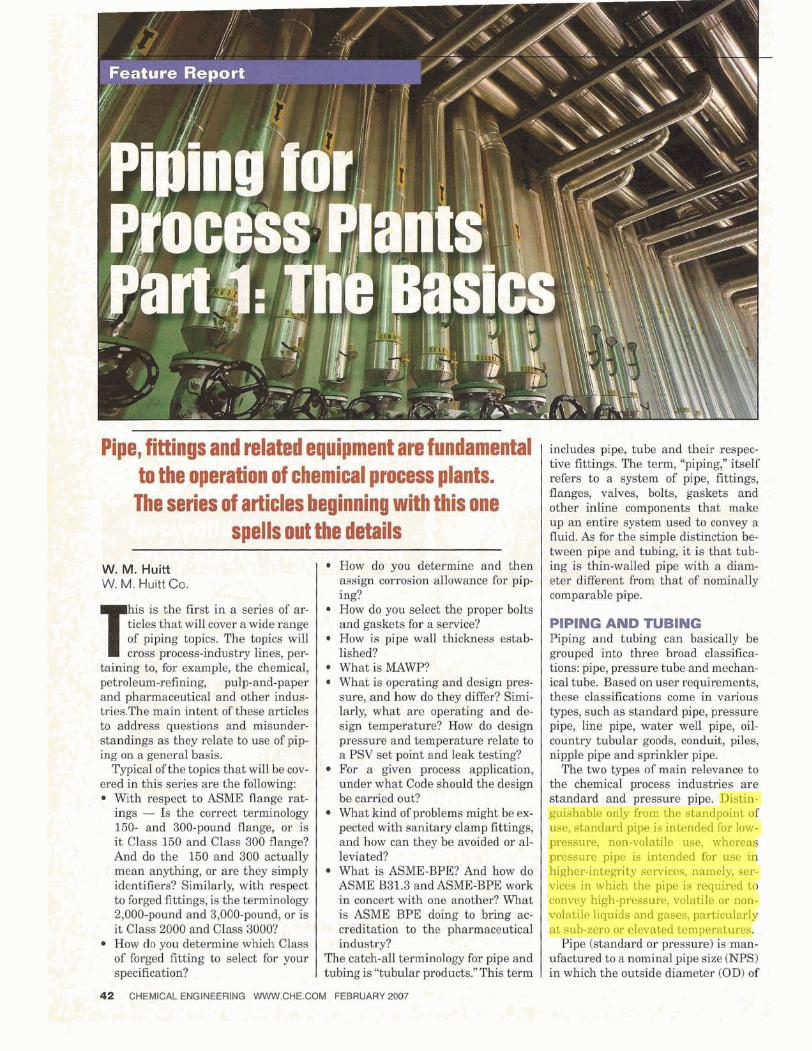
Pipe, fittings and related equipment are fundamenpl I to the operation of chemical process plants.. 'i - . I
- - n
The series of articles beginning with this one!' '
spells out the details JV. M. Huitt iN. M. Huitt Co.
How do you determine and then assign corrosion allowance for pip-
is is the first in a series of ar- ticles that will cover a wide range
topics. The topics will process-industry lines, per-
taining to, for example, the chemical, petroleum-refining, pulp-and-paper and pharmaceutical and other indus- tries.The main intent of these articles to address questions and misunder- standings as they relate to use of pip- ing on a general basis.
Typical of the topics that will be cov- ered in this series are the following:
With respect to ASME flange rat- ings - Is the correct terminology 150- and 300-pound flange, or is i t Class 150 and Class 300 flange?
. - - And do the 150 and 300 actually , mean anything, or are they simply L* . identifiers? Similarly, with respect
to forged fittings, is the terminology , 2,000-pound and 3,000-pound, or is ' i t Class 2000 and Class 3000?
How do you determine which Class of forged fitting to select for your specification?
ing'? How do you select the proper bolts and gaskets for a service? How is pipe wall t ~ c l p q s s esiab- lished? -' :, -.%: . i What is MAWP? What is operating and design pres- sure, and how do they differ? Simi- larly, what are operating and de- sign temperature? How do design pressure and temperature relate to a PSV set point and leak testing? For a given process application, under what Code should the design be carried out? What kind of problems might be ex- pected with sanitary clamp fittings, and how can they be avoided or al- leviated? What is ASME-BPE? And how do ASME B31.3 and ASME-BPE work in concert with one another? What is ASME BPE doing to bring ac- creditation to the pharm_aceutical industry?
The catch-all terminology for pipe and tubing is "tubular products." This term
includes pipe, tube and their respec- tive fittings. The term, "piping," itself refers to a system of pipe, fittings, 1 flanges, valves, bolts, gaskets and j
other inline components that make up an entire system used to convey a fluid. As for the simple distinction be- tween pipe and tubing, it is that tub- ing is thin-walled pipe with a diam- eter different from that of nominally comparable pipe.
PIPING AND TUBING Piping and tubing can basically be grouped into three broad classifica- tions: pipe, pressure tube and mechan- ical tube. Based on user requirements, these classifications come in various types, such as standard pipe, pressure pipe, line pipe, water well pipe, oil- country tubular goods, conduit, piles, nipple pipe and sprinkler pipe.
The two types of main relevance to the chemical process industries are standard and pressure pipe. Distin- guishable only from the standpoint of use, standard pipe is intended for low- pressure, non-volatile use, whereas pressure pipe is intended for use in higher-integrity services, namely, ser- vices in which the pipe is required to convey high-pressure, volatile or non- volatile liquids and gases, particularly at sub-zero or elevated temperatures.
Pipe (standard or pressure) is man- ufactured to a nominal pipe size (NPS) in which the outside diameter (OD) of
42 CHEMICAL ENGINEERING WWW.CHE.COM FEBRUARY 2007 , -- r , ,. . * . ; . .
q 7 F- % *A p * ~ ,4 - . ~ , 1. J v --
a given nominal size remains constant while any change in wall thickness is reflected in the inside diameter (ID). Pipe wall thicknesses are specified by Schedule (Sch.) Numbers 5,10,20,30, 40,60,80,100,120,140 and 160. Add the su& 's' when specifying stainless steel or other alloys. Wall thickness is also specified by the symbols Std. (Standard), XS (Extra Strong) and XX (Double Extra Strong). Pipe of NPS 12 in. and smaller has an OD that is nominally larger than that specsed, whereas pipe with a NPS 14 in. and larger has an OD equal to the size specified.
Steel and alloy tubing is manufac- tured to an OD equal to that speci- fied; this means, for example, that %-in. tubing will in fact have a W-in. OD, and that 2-in. tubing will have a 2-in. OD. This practice also pertains to copper tubing for air conditioning and refrigeration. Copper tubing for other purposes has an OD that is always l/8
-
I
'
in. larger than the diameter specified. As an example, %in. copper tubing will have a 518-in. OD, and 1-in. tubing will have a 1 118-in. 0D.Wall thickness for tubing is specified in the actual decimal equivalent of its thickness.
Manufacturing methods Pipe is manufactured in three basic forms: cast, welded and seamless. Tubing is manufactured in two basic forms: welded and seamless.
Cast Pipe: Cast pipe is available in four basic types: white iron, malleable iron, gray iron and ductile iron. White iron has a high content of carbon in the carbide form. Carbides give it a high compressive strength and a hard- ness that provides added resistance to wear, but leaves it very brittle. The absence of graphite bestows a light colored appearance.
Malleable iron is white cast iron that has been heat treated for added ductility. If white cast iron is reheated
INDUSTRIES AND e". This is a euphemism quite often used among
and engineers. Taken at face value, this IS a true statement - pipe is certainly pipe. However,
taken in context, the statement means that no matter which pro- cerss industry you work in when designing piping systems, the issues are all the same. And in that context, it could not be further from the truth.
in the presence of oxygen-containing materials such as an iron oxide, and allowed it to cool very slowly, the free carbon forms small graphite particles. This gives malleable iron excellent machinability and ductility proper- ties, along with good shock resistant properties.
Gray iron is the oldest form of cast iron pipe and is synonymous with the name, "cast iron." It contains carbon in the form of flake graphite, which gives i t its characteristic gray color. Gray cast iron has virtually no elastic or plastic properties, but has excellent machining and self-lubricating prop- erties due to the graphite content
Ductile iron is arguably the most versatile of the cast irons. It has ex- cellent ductile and machinable prop- erties while also having high strength characteristics. Welded Steel Pipe ( a d Trcbing): Statements made about pipe in the this section also pertain to tubing.
STANDARDS The point i s not that the pharmaceutical industry itself is young;
as already stated, it is not. The point is that the standards and accepted practices a propriate for state-of-the-art design, en- gineering and manu P acture are. As recently as the ast fifteen or so years, industry practice, including dimensiona P standards for high purity fittings, were left to the resources of the phar- maceutical company owner or their engineering firm (en ineer
4. Consider in particular the pharmaceutical industry. Although not -' 4 new per se, it i s a relative newcomer to the idea of dedicated
desi n, engineering and construction principles, when compared to ot f er process industries, such as refining, bulk chemi- cals, and pulp and paper industries; indeed, even in comparison with nuclear power, and with semiconductor manufacture. Here is a frame of reference, in terms of relevant standard-setting orga- nizations: the American Society of Mechanical Engineers (ASME) was established in 1880; the American Petroleum Institute (API) was established in 191 9; 3-A Standards (for the food and dairy industry) were first developed in the 1920's; the ASME commit- tee for BPVC (Boiler Pressure Vessel Code) Section I11 for nuclear power was proposed in 1963; the Semiconductor Equipment and Materials Institute (SEMI) was established in 1973; the Interna- tional Society of Pharmaceutical Engineers (ISPE) was established in 1980; and ASME Biopharmaceutical Equipment (BPE) issued ik first standard in 1997. Prior to ASME-BPE, the aforementioned 3- A piping standards were the common recourse for facilitating the design of pharmaceutical facilities.
While some of the above standards organizations, and their re- sulting codes and standards, are specific to a particular industry, others are more generalized in their use and are utilized across the various industries. For example, the design and construction of
harmaceutical facility depends upon not only pharma- ceuttcal- a lay K ased standards, codes, guidelines and industry practices such as those generated by ISPE and ASME-BPE; it also avails itself of standards created for other industries. In other words, when designing and constructing a bulk pharmaceutical finishing facility, or a bulk Active Pharmaceutical Ingredient (API) facility, the engineers and constructors will be working under some of the same standards and guidelines as they would when designing and building in other industries such as a refinery or bulk chemical facility.
r O - r r k h r . .I
CHEMICAL ENGINEERING WWW.CHE.COM FEBRUARY 2007 43
of record). The same point applied to construction metho B s and procedures, including materials of construction. These require- ments were basically established for each project and were very dependent upon what the owner's personnel and the engineering firm brought to the table. Industry standards did not exist. With r ard to materials of construction, the ongoing evolution
of techno f ogy (science and engineering alike) has raised expec- tations throughout industry For instance, out of the research and development that went into the Hubble Space Telescope came new methodolo y and technology to better measure and define the limits of sur 3 ace roughness required in material used in hy- gienic-fluid-service contact pi ing. This capability is of particular interest to the pharmaceutica P and biopharmaceutical industries (as well as the semiconductor industry), where cross-contamina- tion at the molecular level cannot be tolerated in many cases. This requires surfaces to be very cleanable.
Surface roughness used to be expressed as polish numbers (i.e., #4 or #7) then grit numbers such as 150, 180 or 240). The prob- lem with either of these two methods lay in their subiectivi their These indicators were not specific enoug X and and the accept/reject result relied too much on a subiective visual verification. There will be more on surface finish requirements in a subsequent installment. With acute awareness of the ongoing problems currently faced
in the pharmaceutical industry and, for altogether different rea- sons, the semiconductor industry, various standards organiza- tions have taken steps to alleviate the consistent problems that have pla ued the industry in the past with, for instasnce, high
urity we B ding issues, standardization of fittings, and guidelines k r industry practice. This series of articles will discuss some of the finer points of these issues, and, in some cases, what the standards organizations, are doing to promote and consolidate some of the better thinking* in, thisbindustry and in this field. CI
, -- { w , 7 . *w 1
I t Nominal plpe I Feature Report
wail thickness
Welded steel pipe is manufactured by furnace welding or by fusion weld- ing. Furnace welding is achieved by heating strip steel, also referred as skelp, to welding temperature then forming it into pipe. The continuous weld, or buttweld, is forged at the time the strip is formed into pipe. This is a process generally used to manufacture low-cost ~ i ~ e 3 ?h in. OD and below.
usi ion- welded pipe is formed from skelp that is cold rolled into pipe and the edges welded together by resis- tance welding, induction welding or arc welding. Electric resistance welding (ERW) can be accomplished by flash welding, high-frequency or low-fre- quency resistance welding. A scarfing tool is used to remove upset material along the seam of flash-welded pipe.
Flash welding produces a high- strength steel pipe in NPS 4 in. through 36 in. Low-frequency resis- tance welding can be used to manu- facture pipe through NPS 22 in. High- frequency resistance welding can be used to manufacture pipe through NPS 42 in.
High-frequency induction welding can be used for high-rate production of small-NPS (6 in. and less) pipe. This is a cleaner form of welding in which scarfing, or the cleaning of upset ma- terial along the seam, is normally not required.
Arc welding the longitudinal seam of production pipe is accomplished with submerged arc welding (SAW), inert gas tungsten arc welding (GTAW) also called tungsten inert gas weld- ing (TIG), or gas shielded consumable metal arc welding (MIG).
As will be discussed later in this series, the type of weld seam used in the manufacture of pipe is a factor when calculating the Pressure Design Thickness (t) of the pipe wall. Some types of longitudinal pipe seam weld- ing are not as strong as others, reduc- ing the overall integrity of the pipe wall by a percentage factyor given in ASME B31.3 based on the type of lon- gitudinal seam weld. Seamless Steel Pipe and Tubing: Statements in the following also per- tain to tubing.
Seamless steel pipe, made using various extrusion and mandrel mill methods, is manufactured by first cre-
ating a tube hollow from a steel billet, which is a solid steel round. The billet is heated to its hot metal forming temperature, then pierced by a rotary piercer or by a press piercer to cre- ate the tube hollow, which .will have a larger diam- eter and thicker wall than
C, (Min.) = 1 .Wt but not less than 0.12 (3.0 mm)
f (2.0 mm) before welding
in.
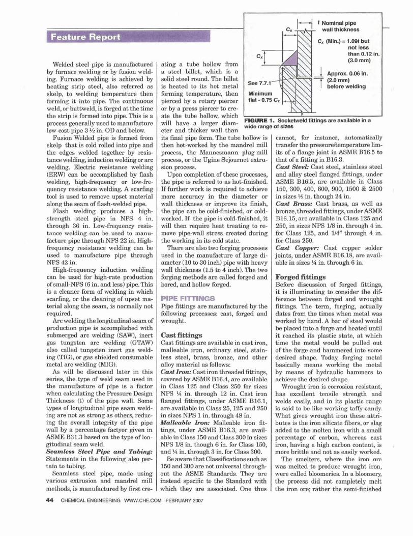
FIQURE 1. Socketweld flttlngs are available in a wide range of slzes
its final pipe form. The tube hollow is then hot-worked by the mandrel mill process, the Mannesmann plug-mill process, or the Ugine Sejournet extru- sion process.
Upon completion of these processes, the pipe is referred to as hot-finished. If further work is required to achieve more accuracy in the diameter or wall thickness or improve its finish, the pipe can be cold-finished, or cold- worked. If the pipe is cold-finished, it will then require heat treating to re- move pipe-wall stress created during the working in its cold state.
There are also two forging processes used in the manufacture of large di- ameter (10 to 30 inch) pipe with heavy wall thickness (1.5 to 4 inch). The Cwo forging methods are called forged and bored, and hollow forged.
PIPE FITTINGS Pipe fittings are manufactured by the following processes: cast, forged and wrought.
Cast fittings Cast fittings are available in cast iron, malleable iron, ordinary steel, stain- less steel, brass, bronze, and other alloy material as follows: Cast Imn: Cast iron threaded fittings, covered by ASME B16.4, are available in Class 125 and Class 250 for sizes NPS 1/4 in. through 12 in. Cast iron flanged fittings, under ASME B16.1, are available in Class 25,125 and 250 in sizes NPS 1 in. through 48 in. Malleable Iron: Malleable iron fib tings, under ASME B16.3, are avail- able in Class 150 and Class 300 in sizes NPS 118 in. though 6 in. for Class 150, and ?4 in. through 3 in. for Class 300.
Be aware that Classifications such as 150 and 300 are not universal through- out the ASME Standards. They are instead specific to the Standard with which they are associated. One thus
cannot, for instance, automatically transfer the pressdtemperature lim- its of a flange joint in ASME B16.5 to that of a fitting in B16.3. Cast Steel: Cast steel, stainless steel and alloy steel flanged fittings, under ASME B16.5, are available in Class 150, 300, 400,600,900, 1500 & 2500 in sizes 34 in. though 24 in. Cast Brass Cast brass, as well as bronze, threaded fittings, under ASME B16.15, are available in Class 125 and 250, in sizes NPS l/8 in. through 4 in. for Class 125, and U4" through 4 in. for Class 250. Cast Coppec Cast copper solder joints, under ASME B16.18, are avail- able in sizes % in. through 6 in.
Forged fittings Before discussion of forged fittings, i t is illuminating to consider the dif- ference between forged and wrought fittings. The term, forging, actually dates from the times when metal was worked by hand. A bar of steel would be placed into a forge and heated until it reached its plastic state, at which time the metal would be pulled out of the forge and hammered into some desired shape. Today, forging metal basically means working the metal by means of hydraulic hammers to achieve the desired shape.
Wrought iron is corrosion resistant, has excellent tensile strength and welds easily, and in its plastic range is said to be like working taffy candy. What gives wrought iron these attri- butes is the iron silicate fibers, or slag added to the molten iron with a small percentage of carbon, whereas cast iron, having a high carbon content, is more brittle and not as easily worked.
The smelters, where the iron ore was melted to produce wrought iron, were called bloomeries. In a bloomery, the process did not completely melt the iron ore; rather the semi-finished
44 CHEMICAL ENGINEERING WWW.CHE.COM FEBRUARY 2007
product was a spongy molten mass called a bloom. a term derived from
-
the red glow bf the molten metal, which is likewise how the process gets its name. The slag and impuri- ties were then mechanically removed from the molten mass by twisting and
PLASTIC-LINED n the main body of this article, we have touched on iust some of the key points related to metal pipe and fittings, while not consider- I. ing plastic lined pipe systems and nonmetallic pi ing. Nonmetallic
piping merits a discussion on its own, and shoul cf' not be relegated to a paragraph or two here. On the other hand, since lined pipe is steel pipe with a liner, and i s so widely used in the process industries, it is worthwhile to present the relevant basics here. When first introduced, lined pipe filled a large fluid-han-
dling gap in industry, but brought with it some technical issues. In particular, when various manufacturers began producing lined pipe and fittings, industry standards for them did not exist. Conse- quently, there were no standard fitting dimensions, and the avail- ability of size and type of fittings would vary from one company to another (as they still do, to a much lesser degree). Due to the auton- omous nature of lined pipe manufacturing during its initial stages, the piping designer for a process lant would have to know early in the design process which manu P acturer he or she were going to use. Particularly in fitting-makeup situations, in which a 90-deg elbow might be bolted to a tee, which in turn might br bolted to another 90-deg elbow it was important to know in advance what those makeup dimensions were going to be, and thus the identity of the fitting manufacturer.
While the lack of industry standard dimensions was a design problem, other operational type problems existed as well. Some of the fluid services for which these lined pipe systems were specified for (and still are) would normally be expected to operate under a positive pressure, but at times would phase into a negative pres- sure. The liners in the early systems were not necessarily vacuum- rated, and consequently would colla seat times under the negative internal pressure, ing the pipehe. B There was an adde problem when gaskets were thrown into the mix. Gaskets were not normally required unless frequent dis- mantling was planned; even so, many firms, both engineering and manufacturers, felt more secure in speciFying gaskets at every joint. When required, the gasket of choice, in many cases, was an en- velope type asket made of PTFE (polytetrafluoroethylene) with an inner core o Y various filler material, such as EPDM. These gaskets had a tendency to creep under required bolt-torque pressure at ambient conditions. From the time at which a system was installed to the time it was ready to hydrotest, the gaskets would, on many occasion, creep, or relax to the point of reducing the compressive bolt load of the ioint enough to where it would not stand up to the hydrotest pressure. Quite often, leaks would become apparent dur- ing the fill cycle prior to testing.
hammering, which is where the term
PIPE Other problems that still exist are those of permeation with regard to
PTFE liner material, as well as that of internal and external triboelectric charge generation and accumulation (static electricity). But, due to the dili ent efforts of the lined pipe and gasket industries, these types of pro I lems have either been largely eliminated or controlled.
Even so, the designer employing lined pipe should keep the poten- tial for static-electricity problems in mind. If electrical charge gen- eration i s allowed to continually dissipate to ground, then there is no charge buildup and no problem. That is what occurs with steel pipe in contact with a flowing fluid: charge generation has a path to ground, and does not have an opportunity to build u . With regard to thermoplastic lined pipe, there are two issues to K e considered: external charge accumulation and internal charge accumulation. Ex- perience and expertise are needed in order to analyze a particular situation. A subsequent installment of this series will provide basic information that will at least allow you to be familiar with the subject, and help you to understand the issues.
Fitting dimensions for lined pipe have been standardized through ASTM F1545 in referencing ASME 816.1 (cast iron fittings), B16.5 (steel fittings) and B16.42 (ductile iron fittings). Note 3 under Sub- Para. 4.2.4 of ASTM F1545 states, "Center-to-face dimensions include the plastic lining," which means that the dimensions given in the referenced ASME standards are to the bare metal face of the fittings. However, when lined fittings are manufactured, the metal casting is modified to accommodate the liner thickness being in- cluded in that same specified center-to-face dimension.
With regard to vacuum rating, liner specifications have been greatly improved, but it is prudent to check the vacuum ratings of available pipe and fittings with each manufacturer under consid- eration. This rating is likely to vary from manufacturer to manu- facturer depending on diameter, fitting, liner type, pressure and temperature. Gasket materials such as PTFE/Silicate composite or 100% expanded PTFE, have been developed to reduce the gasket creep rate in a gasket material.
Permeation issues with PTFE liners (these issues also arise, to a lesser extent, with other liner material) have been accommodated more than resolved with the use of vents in the steel pipe casing, the application of vent components at the flange ioint, and increased liner thickness.
Standard sizes of plastic lined pipe and fittings ran e from NPS 1 in. through 12 in. And at least one lined-pipe manu 7 acturer, also manufactures larger-diameter pipe and fittings: from NPS 14 in. through 24 in., and when requested can manufacture spools to 144 in. diameter. CI
wrought originates. Today forged and wrought are al-
most synonymous.ASTMA234, "Stan- dard Specification for Piping Fittings of Wrought Carbon Steel and Alloy Steel for Moderate and High Tem- perature Service" states in Para 4.1 and in Para 5.1 that wrought fittings made under A234 are actually manu- factured or fabricated from material pre-formed by one of the methods listed previously, which includes forg- ing. In ASTM A961, "Standard Specifi- cation for Common Requirements for
Steel Flanges, Forged Fittings, Valves and Parts for Piping Applications," the definition for the term Forged is, "the product of a substantially compres- sive hot or cold plastic working op- eration that consolidates the material and produces the required shape. The plastic working must be performed by a forging machine, such as a hammer, press, or ring rolling machine, and must deform the material to produce a wrought structure throughout the material cross section."
The difference, therefore, between foivged and wrought fittings is that forged fittings, simply put, are manu- factured from bar, which while in its plastic state is formed into a fitting with the use of a hammer, press or rolling machine. Wrought fittings, on the other hand, are manufactured from killed steel, forgings, bars, plates
and seamless or fusion welded tubu- lar products that are shaped by ham- mering, pressing, piercing, extruding, upsetting, rolling, bending, fusion welding, machining, or by a combina- tion of two or more of these operations. In simpler terms wrought signifies "worked". There are exceptions in the manufacture of both, but that is the general difference.*
*A point concernin the ASTM specifications is worth noting. In referring to ASTM A961 above, I am quoting from what ASTM refers to as a General Requirement Specification. Such a spec- ification is one that covers requirements typical for multiple individual Product Specificntions. In this case. the individual Product S~ecifications covered tiy A961 are A105, A181, h 8 2 , A360, A694, A707, A727 and A836.
The reason I point this out is that many de- signers and engineers are not aware that when reviewing an A105 or any of the other ASTM individual Product Specifications you may need to include the associated General Requirement Specification in that review. Reference to a Gen- eral Requirement Specification can be found in the respective Product Specification.
CHEMICAL ENGINEERING WWW.CHE.COM FEBRUARY 2007 45
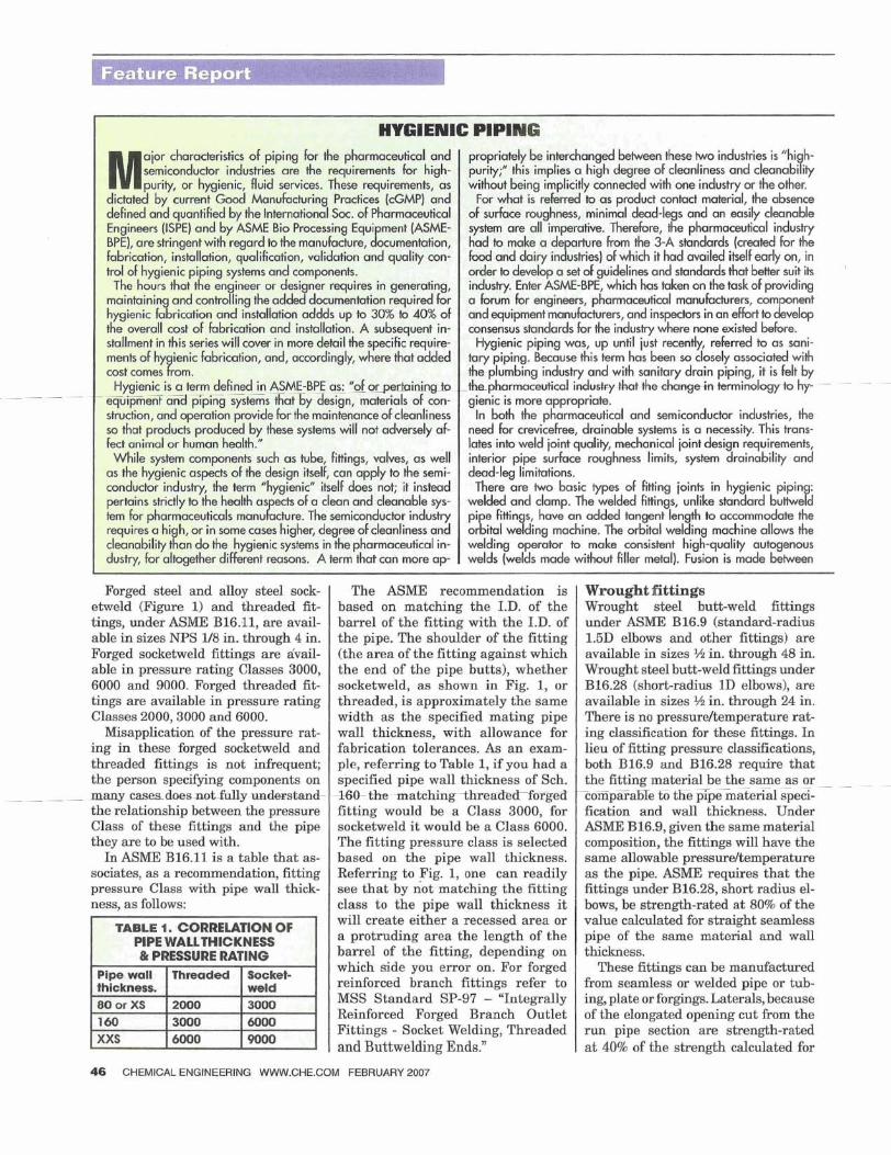
Forged steel and alloy steel sock- etweld (Figure 1) and threaded fit- tings, under ASME B16.11, are avail- able in sizes NPS l/8 in. through 4 in. Forged socketweld fittings are avail- able in pressure rating Classes 3000, 6000 and 9000. Forged threaded fit- tings are available in pressure rating Classes 2000,3000 and 6000.
Misapplication of the pressure rat- ing in these forged socketweld and threaded fittings is not infrequent; the person specifying components on many_casesdQe-tta- the relationship between the pressure Class of these fittings and the pipe they are to be used with.
In ASME B16.11 is a table that as- sociates, as a recommendation, fitting pressure Class with pipe wall thick- ness, as follows:
HYGIENIC PIPING
M ajor characteristics of piping for the pharmaceutical and semiconductor industries are the requirernenk for high- purity, or hygienic, fluid services. These requirements, as
dictated by current Good Manufacturing Practices (cGMP) and defined and quantified by the International Soc. of Pharmaceutical
hygienic fabrication and installation addds up to 30% to 40% of the overall cost of fabrication and installation. A subsequent in- stallrnent in this series will cover in more detail the specific require- ments of hy ienic fabrication, and, accordingly, where that added cost comes Y rom.
Hygienic is a term defined in ASME-BPE as: "of or quipme3 aTdj%pKg G t G s X a t by design, materials of con- struction, and operation provide for the maintenance of cleanliness so that products produced by these systems will not adversely af- fect animal or human health." While system componenk such as tube, fittings, valves, as well
as the hygienic aspects of the design itself, can apply to the semi- conductor industry, the term "hygienic" itself does not; it instead
r pertains strictly to the health as ts of a clean and cleanable sys- tem for pharmaceuticals manu cture. The semiconductor indusiry requires a hi h, or in some cases higher, degree of cleanliness and cleanability # an do the hygienic systems in the pharmaceutical in- dustry, for altogether different reasons. A term hat can more ap-
The ASME recommendation is based on matching the I.D. of the barrel of the fitting with the I.D. of the pipe. The shoulder of the fitting (the area of the fitting against which the end of the pipe butts), whether socketweld, a s shown in Fig. 1, or threaded, is approximately the same width as the specified mating pipe wall thickness, with allowance for fabrication tolerances. As an exam- ple, referring to Table 1, if you had a specified pipe wall thickness of Sch.
4 X b the r n a t c h m g t ~ ~ e ~ ~ g e 3 fitting would be a Class 3000, for socketweld i t would be a Class 6000. The fitting pressure class is selected based on the pipe wall thickness. Referring to Fig. 1, one can readily see that by not matching the fitting class to the pipe wall thickness it will create either a recessed area or a protruding area the length of the barrel of the fitting, depending on which side you error on. For forged reinforced branch fittings refer to MSS Standard SP-97 - "Integrally Reinforced Forged Branch Outlet Fittings - Socket Welding, Threaded and Buttwelding Ends."
propriately be interchanged between these two industries is "hi h- purity;" this implies a high degree of cleanliness and deanabky without being implicitly connected with one industry or the other.
For what is referred to as product contact material, the absence of surface roughness, minimal deud-legs and an easily cleanable system are all impemtive. Therefore, the pharmaceutical industry had to make a rture from the 3-A standards (created for the food and dairy in *s" ustries) of which it had availed itself early on, in order to develop a set of guidelines and standards that be^ suit its industry. Enter ASME-BPE, which has taken on the task of providing a forum for engineers, pharmaceutical manufacturers, corn nent and equipment manufadurers, and inspectors in an efb* to Lop consensus standards for he industry where none existed before.
Hygienic piping was, up until just recently, referred to as sani- tary piping. Because this term has been so closely associated with h e plumbing industry and with sanitary drain piping, it is felt by
pertainingf~pthapharmaceutid in$&ty-tka+tke&mg& krminokgyb hy- - gienic is more appropriate.
In both the pharmaceutical and semiconductor industries, the need for crevicefree, drainable systems is a necessity. This trans- lates into weld joint quality, mechanical ioint design requirements, interior pipe surface roughness limits, system drainability and dead-leg limitations. There are two basic types of fitting joints in hygienic pipin : B welded and clamp. The welded fittings, unlike standard butiwe d
pi e fittin s, have an added tangent len th to accommodate the oXital wedding machine. The orbital weding machine allows the welding operator to make consistent high-quality autogenous welds (welds made without filler metal). Fusion is made between
TABLE 1. CORRELATION OF PIPE WALLTHICKNESS & PRESSURE RATING
Wrought fittings Wrought steel butt-weld fittings under ASME B16.9 (standard-radius 1.5D elbows and other fittings) are available in sizes W in. through 48 in. Wrought steel butt-weld fittings under B16.28 (short-radius 1D elbows), are available in sizes W in. through 24 in. There is no pressureltemperature rat- ing classification for these fittings. In lieu of fitting pressure classifications, both B16.9 and B16.28 require that the fitting material be the same as or - - -
cornparamel% E e pipcmSerialTpeci- fication and wall thickness. Under ASME B16.9, given the same material composition, the fittings will have the same allowable pressure/temperature as the pipe. ASME requires that the fittings under B16.28, short radius el- bows, be strength-rated at 80% of the value calculated for straight seamless pipe of the same material and wall thickness.
These fittings can be manufactured from seamless or welded pipe or tub- ing, plate or forgings. Laterals, because of the elongated opening cut from the run pipe section are strength-rated a t 40% of the strength calculated for
Pipe wall thickness. 80 or XS
160 XXS
46 CHEMICAL ENGINEERING WWW.CHE.COM FEBRUARY 2007
Threaded
2000 3000 6000
Socket- weld 3000 6000 9000
CHEMICAL ENGINEERING WWW.CHE.COM FEBRUARY 2007 47
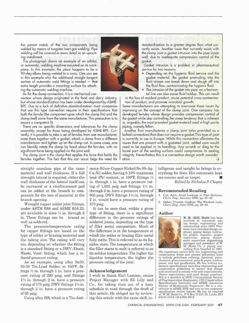
the parent metals of the two components being standarcilzation to a greater degree than what cur- welded by means of tungsten inert gas welding. Pipe I rently exists. Another issue that currently exists with welding will be covered in more detail in an upcom- the clamp ioint is gasket intrusion into the pipe inside in installment. wall, due to inadequate compression control of the Tae photograph shows an example of an orbital, gasket.
or automatic, weldin machine mounted on its work- 9 Gasket intrusion is a problem in pharmaceutical piece. In this examp e, the piece happens to be a ice for two reasons: 90-deg elbow being welded to a cross. One can see Depending on the hygienic fluid service and the in this example why the additional strai ht tangent B asket material, the gasket protruding into the section of automatic weld fittings is nee ed - that Wuid siream can break down and slough off into extra length provides a mounting surface for attach- the fluid flow, contaminating the hygienic fluid ing the automatic welding machine. The intrusion of the gasket into pipe on a horizon- As for the clamp connection, it is a mechanical con- tal line can also cause fluid holdup. This can result
nection whose design originated in the food and dairy industry, in the loss of residual product, cause potential cross-contamina- but whose standardization has been under development by ASME- tion of product, and promote microbial growth. BPE. Due to a lack of definitive standardization, most companies Some manufacturers are atternptin to overcome these issues by
P f that use this type connection require in their s ecifications that improving on the concept of the camp joint. One company has both the ferrule (the component upon which the camp fits) and the developed ferrules whose design provides compression control of clamp itself come from the same manufacturer. This precaution i s to the gasket while also controlling the creep tendency that i s inherent ensure a competent fit. in, arguably, the most prevalent gasket material used in high purity There are no specific dimensions and tolerances For the clamp piping, namely,Teflon.
assembly, except for those being developed by ASME-BPE. Cur- Another firm manufactures a clamp joint (also provided as a rently, it is possible to take a set of Ferrules from one manufacturer, bolted connection) that does not require a gasket.This pe of joint 7 mate them together with a gasket, attach a clamp from a different is currently in use in Europe. While this connection al eviates the manufacturer and tighten up on the clamp nut. In some cases, one issues that are present with a gasketed ioint, added care would can literally rotate the clamp by hand about the ferrules, with no need to be applied in its handling. Any scratch or ding to the significant force being applied on the joint seal. faced part of the sealing surface could compromise its sealing The clamp joint is the clamp that applies the force that holds the integrity. Nevertheless this is a connection design worth consider-
ferrules together. The fact that this can occur begs the need for ation. CI
straight seamless pipe of the same material and wall thickness. If a full strength lateral is required, either the wall thickness of the lateral itself can be increased or a reinforcement pad can be added at the branch to com- pensate for the loss of material at the branch opening.
Wrought copper solder joint fittings, under ASTM B88 and ASME B16.22, are available in sizes ?4 in. through 6 in. These fittings can be brazed as well as soldered.
The pressureltemperature rating for copper fittings are based on the type of solder or brazing material and the tubing size. The rating will vary too, depending on whether the fitting is a standard fitting or a DWV (Drain, Waste, Vent) fitting, which has a re- duced pressure rating.
As an example, using alloy Sn50, 50-50 Tin-Lead Solder, at 100°F, fit- tings % in. through 1 in, have a pres- sure rating of 200 psig, and fittings 1% in. through 2 in. have a pressure rating of 175 psig. DWV fittings 1% in. through 2 in. have a pressure rating of 95 psig.
Using alloy HB, which is a Tin-Anti-
mony-Silver-Copper-Nickel(Sn-Sb-Ag- telligence and insight he brings to ev- Cu-Ni) solder, having 0.10% maximum erything he does. His comments kept lead (Pb) content, at 100°F, fittings $4 me concise and on target. H in. through 1 in. have a pressure rat- Edited by Nicholas l? Chopey ing of 1,035 psig and fittings 1% in. through 2 in. have a pressure rating of Recommended Reading 805 psig. DWV fittings 1% in, through 1. Cox, John, Avoid Leakage in Pipe SYS~-=-,
Chem. E r g , January 2006, pp. 4043. in. have a pressure rating of 2. Sahoo, Trinath, Gaskets: The Weakest Link,
370 psig. Chem. Eng. , June 2005, pp. 38-40. It can be seen that, within a given
type of fitting, there is a significant Author difference in the pressure ratings of W. M. (Bill) Huitt has been
soldered joints, depending on the type involved in industrial p i p ing design, engineering and
of filler metal composition. Much of construction since 1965. Posi-
the difference is in the temperature at tions have included design en- gineer, piping design instruc-
which the solder or brazing filler metal tor, project engineer, supervisor,
fully melts. This is referred to as its liq- piping cf''$A:
ment supervisor, engineerin uidus state. The temperature at which manager and president of d
M. Huitt Co. a i ing con- the filler starts to melt is referred to as its solidus temperature. The higher the liquidus kmperature, the higher the pressure rating of the joint.
Acknowledgement I wish to thank Earl Lamson, senior Project Manager with Eli Lilly and Co., for taking time out of a busy schedule t o read through the draft of this article. He obliged me by review- ing this article with the same skill, in-
sulting firm founBeB in 1987.
~ , " ~ , " , " ~ , " ~ f i " ~ ~ ~ ~ , " , h , " s ~ ~ , " $ ~ g ~ ~ to include etroleurn refining, chemical, petro- chemical, garxnaceutical, pul & paper, nuclear power, anzcoal gasification. Ife has written nu- merous specifications including engineering and construction guidelines to ensure that design and construction comply with code requirements,
~ ~ ~ , " , " , " ~ ~ ~ ~ , " f " I $ ~ ~ $ ~ , " ~ ~ ~ { & ~ , " t " y ofPharmaceuticalEngineers), CSI(Construction
~ , " ~ ~ " , ~ ~ ~ , ~ , " i ~ ~ ~ , " ~ ~ ~ " ; " ~ ~ ~ ~ ~ ~ tributor ~OASME-BPE on two corporate specilication review boards. He can be reached at: W. M. Huitt Co., P 0 Box 31154, St. Louis, MO 63131-01541 (314)966-8919