Embed Size (px)
Citation preview
Article
The effects of short pulse laser surface cleaning on porosity formation and reduction in laser welding of aluminium alloy for automotive component manufacture
AlShaer, Ahmad Wael, Li, L. and Mistry, A.
Available at http://clok.uclan.ac.uk/18252/
AlShaer, Ahmad Wael, Li, L. and Mistry, A. (2014) The effects of short pulse laser surface cleaning on porosity formation and reduction in laser welding of aluminium alloy for automotive component manufacture. Optics and Laser Technology, 64 . pp. 162171. ISSN 00303992
It is advisable to refer to the publisher’s version if you intend to cite from the work.http://dx.doi.org/10.1016/j.optlastec.2014.05.010
For more information about UCLan’s research in this area go to http://www.uclan.ac.uk/researchgroups/ and search for <name of research Group>.
For information about Research generally at UCLan please go to http://www.uclan.ac.uk/research/
All outputs in CLoK are protected by Intellectual Property Rights law, includingCopyright law. Copyright, IPR and Moral Rights for the works on this site are retained by the individual authors and/or other copyright owners. Terms and conditions for use of this material are defined in the http://clok.uclan.ac.uk/policies/
CLoKCentral Lancashire online Knowledgewww.clok.uclan.ac.uk

1
The effects of short pulse laser surface cleaning on porosity
formation and reduction in laser welding of aluminium alloy for
automotive component manufacture
A.W.AlShaer1, L.Li1 and A.Mistry 2
1 Laser Processing Research Centre, School of Mechanical, Aerospace and Civil Engineering,
The University of Manchester, Manchester, M13 9PL, UK
2Advanced Manufacturing Engineering, Jaguar – Land Rover, Banbury Road, Gaydon,
Warwick CV 35 0RR, UK
Abstract
Laser welding of aluminium alloys typically results in porosity in the fusion zones, leading to
poor mechanical and corrosion performances. Mechanical and chemical cleaning of surfaces
have been used previously to remove contaminants for weld joint preparations. However, these
methods are slow, ineffective (e.g. due to hydrogen trapping) or lead to environmental hazards.
This paper reports the effects of short pulsed laser surface cleaning on the porosity formation in
laser welding of AC-170PX (AA6014) aluminium sheets (coated with Ti/Zr and lubricated
using a dry lubricant AlO70) with two types of joints: fillet edge and flange couch, using an
AA4043 filler wire for automotive component assembly. The effect of laser cleaning on
porosity reduction during laser welding using a filler wire has not been reported before. In this
work, porosity and weld fusion zone geometry were examined prior to and after laser cleaning.
The nanosecond pulsed Nd:YAG laser cleaning was found to reduce porosity significantly in
the weld fusion zones. For the fillet edge welds, porosity was reduced to less than 0.5%
compared with 10-80% without laser cleaning. For flange couch welds, porosity was reduced to
0.23 - 0.8% from 0.7 – 4.3% without laser cleaning. This has been found to be due to the
elimination of contaminations and oxide layers that contribute to the porosity formation. The
laser cleaning is based on thermal ablation.

2
Key words: Laser welding, laser cleaning, fillet edge joint, flange couch joint, porosity,
aluminium alloy, automotive
1. Introduction
Lightweight alloys such as aluminium alloys usually have a layer of oxide or hydroxides on
their surfaces. These types of surface layers may affect fusion joining processes due to
hydrogen entrapment in the fusion zones1. Various approaches were reported on the elimination
of surface oxide layers before welding. The use of chemical substances is the main method to
remove the oxide layer2. Sand blasting, silicon carbide polishing and plasma etching were also
reported as weld surface preparation methods3, 4. Most cleaning methods used in the past
depend on chemical substances that react with the metal on the surface. These methods were
referred to as wet cleaning. Although it can remove the undesirable layer, the use of these
substances and their storage may harm the workers’ health and can raise environment and
safety risks5. Furthermore, due to the use of fluid in cleaning, hydrogen trapping was difficult
to avoid, which would cause porosity in welds.
Lasers have been used in many industrial applications such as drilling, cutting, machining and
recently for surface cleaning6. Laser cleaning is usually considered to be one of the dry
cleaning methods. It should be noted that not all lasers are suitable for cleaning applications.
Laser dry cleaning leads to particle or film ejection from the surface using high power laser
pulses. Ejection of contaminants from the surface is achieved due to the sudden expansion of
the particles or the surface or by evaporation. According to the laser wavelength and the type of
the substrate material, the irradiation energy is absorbed by the surface, a particle or the
contaminated film7. Tam et al. found that the ejection acceleration (~1010cm/s) given to a
particle by the laser radiation is much greater than gravitational acceleration8. This results in
particles ejection without melting the surface. Their study shows that higher laser power
intensities, shorter pulse duration and shorter wavelength lead to a high cleaning efficiency.
Contaminant particles adhere usually to the metallic surface based on the Van der Waals or
electrostatic forces9. Laser cleaning can remove the contaminating particles according to two
different mechanisms, either by direct ejection of particles which is achieved by vaporisation or
hydrodynamic sputtering, or by thermoplastic expansion of the underneath parent material10.
This means that laser cleaning is achieved when the energy is absorbed either by the
contaminants particles or by the substrate. Sometimes a combination of the two mechanisms
can occur. The energy absorbed by the contaminant can be calculated from11:
3
∆𝐸 =𝐼0𝐴
𝛿𝐵𝐿 ∫ 𝑒−𝑧 𝛿𝐵𝐿⁄ 𝑑𝑧 (1)
𝑑
0
where I0 is the intensity, A is laser spot area, δBL is Beer–Lambert absorption depth and d is the
thickness of the contaminant layer.
Laser cleaning offers many technical advantages such as remote application, localised cleaning,
cleaning of components with complex 3D shapes and elimination of the use of hazardous
chemical solutions. Since lasers that are used in surface preparation should only remove a thin
layer without affecting the bulk material, the selection of the process parameters becomes very
critical. These parameters can include: wavelength, pulse duration, pulse energy, repetition rate,
scanning speed and laser fluence etc5. It should be noted that during the interaction between a
laser beam and metallic alloys, photon-electron harmonic interactions may be observed that are
closely related to the non-linear optical effects12.
One of the successful applications of laser cleaning as a method for weld joint surface
preparation is for Ti6Al4V alloys which have been used for aero-engine manufacture. Many
investigations were conducted on laser cleaning of these alloys. Turner et al.11, 13, 14 investigated
and modelled Nd:YAG and CO2 laser cleaning of the Ti6Al4V alloy. They concluded that the
prevailing effect, in case of YAG laser cleaning, is the heat conducted to the contaminants from
the substrate surface. However, contaminants were removed by direct heating if a CO2 laser is
used. In a further investigation15, they compared the use of CW CO2, pulsed YAG and excimer
lasers for titanium alloys cleaning. Their results showed that photo-chemical ablation takes
place only when the excimer laser was used due to its short wavelength, while thermal
vaporisation becomes dominant in the YAG and CO2 laser cleaning at the selected parameters.
Additionally, oxidation was noticed to be less after pulsed laser cleaning than CW laser
cleaning16. Yue et al.17 investigated the removal of the alpha case in Ti alloys while Marimuthu
et al.18, 19 monitored the TiN removal from WC micro tools and modelled excimer laser
cleaning mechanism of film and particle contamination. They concluded that the peak power
in excimer laser cleaning has more significant influence than the number of pulses. Some
models were created to simulate the laser bending of Ti sheets while others focused on the
estimation of the optimal solution for minimising the surface roughness in end milling of Ti
alloys20.
Different materials were laser cleaned using different lasers such as: AA5083 aluminium alloy
(using a YAG laser)4 and stainless steel (using a YAG laser)10, stainless steel 316L and Inconel
(using an Excimer laser)21, Silicon (a CO2 laser)22, and copper (using a femtosecond Ti-saphire
laser)23.
4
Haboudou et al.4 studied porosity reduction using laser cleaning and other methods for
removing the surface oxide layer on AA5083 and A356 aluminium alloys. They used a pulsed
YAG laser for cleaning with a fluence of 1.5 J/cm2, a scanning speed of 20 mm/s, a frequency
of 20 Hz and a 100 nm pulse length. Their results show that laser cleaning of the surface
reduced porosity in the welds to less than 2% and 7% for A356 and AA5083 respectively. They
attributed the difference in porosity generated in the different materials to the Mg content in
theses alloy since Mg vaporisation increases as Mg content increases. Laser cleaning was found
to be more efficient than mechanical polishing or sand blasting of this type of materials. Meja
et al.24 investigated laser cleaning of anodised aluminium (black anodised) with an oxide layer
thickness of 20 µm using a laser at 248 nm, 532 nm and 1064 nm wavelengths in order to
determine the most efficient radiation for the oxide removal. They concluded that there was a
shift in the energy density threshold at which cleaning took place between 532 nm and 1064 nm
wavelengths. They attributed this to the higher absorption at shorter wavelength. Rechner et
al.16 studied Nd:YAG laser cleaning of an AA6016 aluminium alloy which was coated with a
TiZr oxide layer. They used XPS analysis to confirm the reduction in oxygen and carbon
content on the rolled alloy surface and it showed that laser cleaning had removed a significant
amount of Fe, C, Si, and O2 from the surface. The sheets were subsequently adhered together
using epoxy adhesive and surface cleaning was found to improve the tensile strength joint for
this type of material.
As seen from the literature, research on laser cleaning focused so far mainly on cleaning of
steels, titanium, and very few types of aluminium alloys. Therefore, further research is required
on other Al alloys in order to understand the effect of laser cleaning on weld defects such as
porosity since it is one of the most common problems faced in aluminium welding using high
energy beams such as laser and electron beams. In the previous work, some researchers
discussed the effect of mechanical and chemical cleaning of the surface on laser welding using
a filler wire25-27, while others discussed laser cleaning effect on autogenous Al welding4.
However, the effect of laser cleaning on porosity reduction during laser welding using a filler
wire has not been reported before and laser cleaning of AA6014 aluminium alloy has not been
reported before.
In this study, the effect of laser cleaning as a surface preparation method for laser welding of
AC-170PX (AA6014) is reported. The aluminium sheets were laser cleaned and laser welded.
The porosity, microstructure, and weld dimensions were compared with and without laser
cleaning.

5
2. Materials and Experimental Procedure
AC170-PX aluminium sheets of 1.1 mm thickness were laser welded using AA4043 filler wire
with a diameter of 1.2 mm. The chemical compositions of these materials are given in Table 1.
The parent material has been tempered to T4 (solution heat treated and naturally aged) and its
physical and mechanical properties, which are given in Table 2, were measured in the
transverse direction to rolling direction according to EW 10002 (a tensile test in which the
sample is strained to fracture in order to determine the mechanical properties)28. The base
material was coated with titanium and zirconium (4 mg/m2) and lubricated using a dry lubricant
AlO70 (1.5 g/m2) as part of their sheet metal forming process. The total coating thickness was
calculated to be 0.503 μm since Ti and Zr coatings together were about 3 nm in thickness and
the AlO70 lubricant has a thickness of 0.5 μm.
Table 1 Chemical composition of the aluminium alloys (wt-%)29, 30
Element Si Fe
max.
Cu
max. Mn Mg
Zn
max.
Ti
max.
Cr
max.
Others
each
max.
Others
Total
max.
AC-170PX
(T4) 0.5-0.7 0.35 0.2 0.05-0.2 0.4-0.7 0.1 0.1 0.1 0.05 0.15
AA4043 5.2 0.5 0.1 0.05 0.05 0.1 0.1 0.05 0.15
Table 2 Physical and mechanical properties of AC-170PX and AA4043 filler wire29, 30
Alloy Density
[103 kg/m3]
Yield
Strength
(0.2%)
[MPa]
Thermal
Conductivity
[W/m.K]
Electrical
Conductivity
[m/Ωmm2]
Coefficient of
Thermal Expansion
[10-6 K-1]
Rm
[MPa]
≥175
AC-170PX
(T4) 2.7 90 160-190 26-30 23.4 195
AA4043 2.68 40 170 24-32 22.1 160
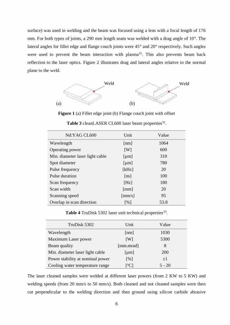
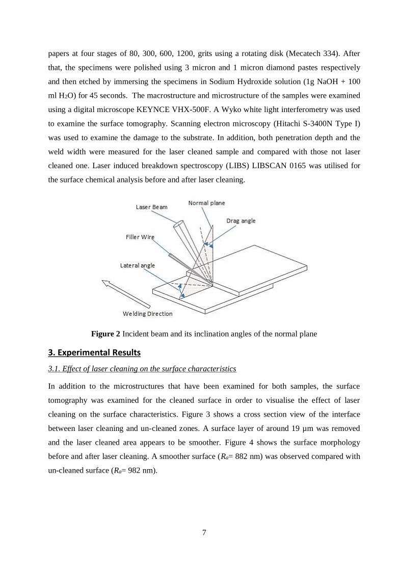
Two different joint configurations were examined in this work: fillet edge and flange couch
joints (Figure 1). Before laser welding, samples were cleaned using a Q-switched Nd:YAG
laser (CleanLASER CL600) supplied by ThyssenKrupp GmbH and operated at the parameters
given in Table 3. After the sheets were cleaned, they were welded using a TRUMPF disk laser
TruDisk 5302 (maximum output power of 5300 W) with the beam properties given in Table 4.
It should be noted that both types of laser used a Gaussian beam shape. The laser welding was
performed with a defocused laser beam with the focal point at of 8 mm above the workpiece
and shielded by argon gas at flow rate of 10 L/min. A 600 µm beam spot (on the workpiece
6
surface) was used in welding and the beam was focused using a lens with a focal length of 176
mm. For both types of joints, a 290 mm length seam was welded with a drag angle of 10°. The
lateral angles for fillet edge and flange couch joints were 45° and 20° respectively. Such angles
were used to prevent the beam interaction with plasma31. This also prevents beam back
reflection to the laser optics. Figure 2 illustrates drag and lateral angles relative to the normal
plane to the weld.
(a) (b)
Figure 1 (a) Fillet edge joint (b) Flange couch joint with offset
Table 3 cleanLASER CL600 laser beam properties32.
Nd:YAG CL600 Unit Value
Wavelength [nm] 1064
Operating power [W] 600
Min. diameter laser light cable [µm] 310
Spot diameter [µm] 780
Pulse frequency [kHz] 20
Pulse duration [ns] 100
Scan frequency [Hz] 180
Scan width [mm] 20
Scanning speed [mm/s] 95
Overlap in scan direction [%] 53.8
Table 4 TruDisk 5302 laser unit technical properties33.
TruDisk 5302 Unit Value
Wavelength [nm] 1030
Maximum Laser power [W] 5300
Beam quality [mm.mrad] 8
Min. diameter laser light cable [µm] 200
Power stability at nominal power [%] ±1
Cooling water temperature range [oC] 5 - 20
The laser cleaned samples were welded at different laser powers (from 2 KW to 5 KW) and
welding speeds (from 20 mm/s to 50 mm/s). Both cleaned and not cleaned samples were then
cut perpendicular to the welding direction and then ground using silicon carbide abrasive
Weld Weld
7
papers at four stages of 80, 300, 600, 1200, grits using a rotating disk (Mecatech 334). After
that, the specimens were polished using 3 micron and 1 micron diamond pastes respectively
and then etched by immersing the specimens in Sodium Hydroxide solution (1g NaOH + 100
ml H2O) for 45 seconds. The macrostructure and microstructure of the samples were examined
using a digital microscope KEYNCE VHX-500F. A Wyko white light interferometry was used
to examine the surface tomography. Scanning electron microscopy (Hitachi S-3400N Type I)
was used to examine the damage to the substrate. In addition, both penetration depth and the
weld width were measured for the laser cleaned sample and compared with those not laser
cleaned one. Laser induced breakdown spectroscopy (LIBS) LIBSCAN 0165 was utilised for
the surface chemical analysis before and after laser cleaning.
Figure 2 Incident beam and its inclination angles of the normal plane
3. Experimental Results
3.1. Effect of laser cleaning on the surface characteristics
In addition to the microstructures that have been examined for both samples, the surface
tomography was examined for the cleaned surface in order to visualise the effect of laser
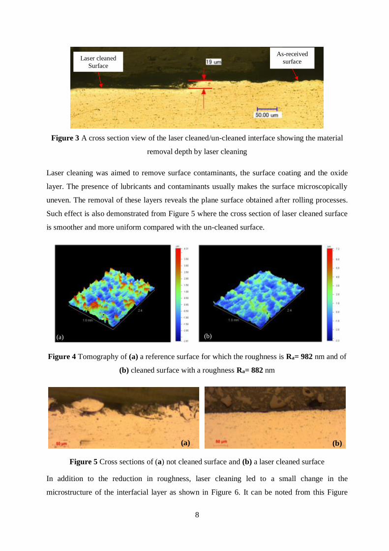
cleaning on the surface characteristics. Figure 3 shows a cross section view of the interface
between laser cleaning and un-cleaned zones. A surface layer of around 19 µm was removed
and the laser cleaned area appears to be smoother. Figure 4 shows the surface morphology
before and after laser cleaning. A smoother surface (Ra= 882 nm) was observed compared with
un-cleaned surface (Ra= 982 nm).
8
Figure 3 A cross section view of the laser cleaned/un-cleaned interface showing the material
removal depth by laser cleaning
Laser cleaning was aimed to remove surface contaminants, the surface coating and the oxide
layer. The presence of lubricants and contaminants usually makes the surface microscopically
uneven. The removal of these layers reveals the plane surface obtained after rolling processes.
Such effect is also demonstrated from Figure 5 where the cross section of laser cleaned surface
is smoother and more uniform compared with the un-cleaned surface.
Figure 4 Tomography of (a) a reference surface for which the roughness is Ra= 982 nm and of
(b) cleaned surface with a roughness Ra= 882 nm
Figure 5 Cross sections of (a) not cleaned surface and (b) a laser cleaned surface
In addition to the reduction in roughness, laser cleaning led to a small change in the
microstructure of the interfacial layer as shown in Figure 6. It can be noted from this Figure
(a) (b)
(a) (b)
Laser cleaned
Surface
As-received
surface
9
that magnesium silicide precipitants that exist in the surface layer are of much smaller in size
than the precipitants located deeply in the bulk material. This can be attributed to the rapid
heating and cooling induced by the laser pulses which do not allow enough time for the
precipitates to grow in comparison with those inside the bulk material.
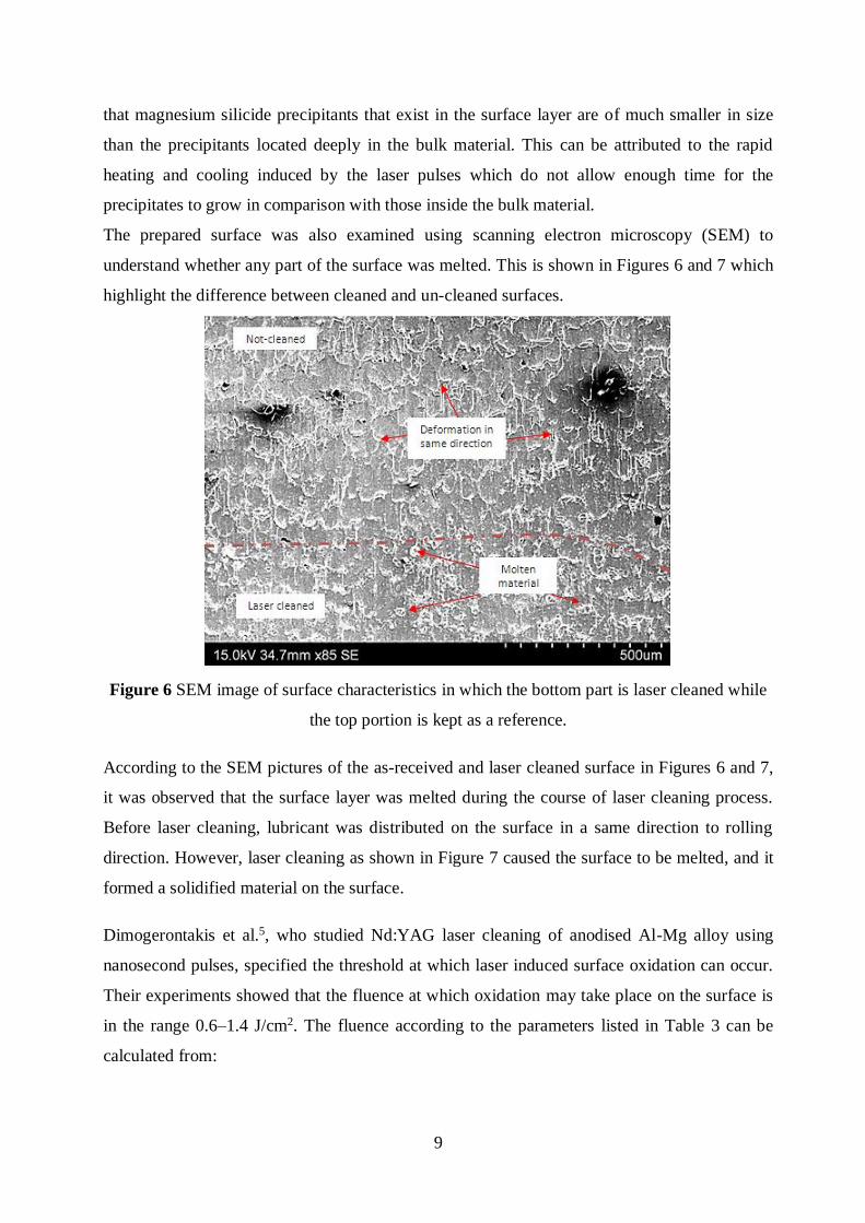
The prepared surface was also examined using scanning electron microscopy (SEM) to
understand whether any part of the surface was melted. This is shown in Figures 6 and 7 which
highlight the difference between cleaned and un-cleaned surfaces.
Figure 6 SEM image of surface characteristics in which the bottom part is laser cleaned while
the top portion is kept as a reference.
According to the SEM pictures of the as-received and laser cleaned surface in Figures 6 and 7,
it was observed that the surface layer was melted during the course of laser cleaning process.
Before laser cleaning, lubricant was distributed on the surface in a same direction to rolling
direction. However, laser cleaning as shown in Figure 7 caused the surface to be melted, and it
formed a solidified material on the surface.
Dimogerontakis et al.5, who studied Nd:YAG laser cleaning of anodised Al-Mg alloy using
nanosecond pulses, specified the threshold at which laser induced surface oxidation can occur.
Their experiments showed that the fluence at which oxidation may take place on the surface is
in the range 0.6–1.4 J/cm2. The fluence according to the parameters listed in Table 3 can be
calculated from:
10
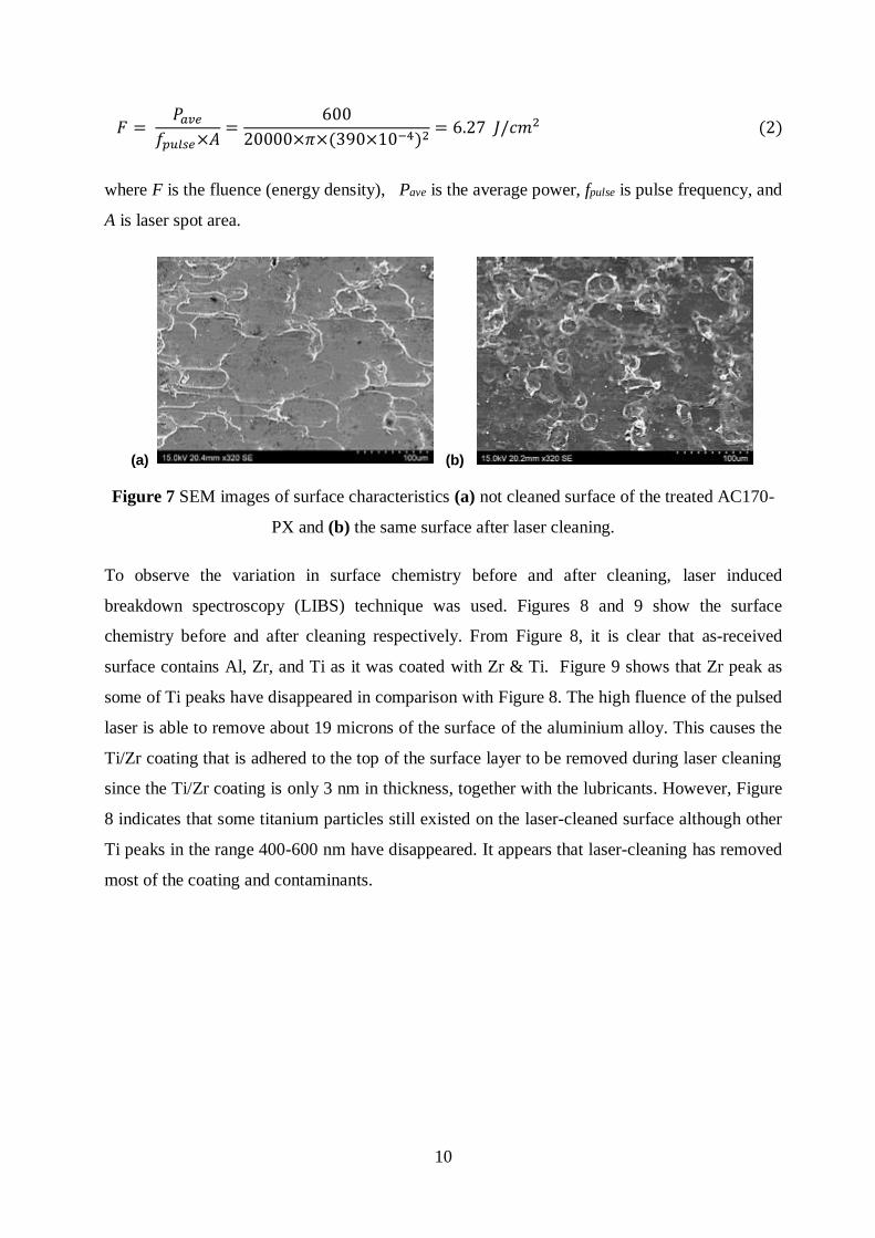
𝐹 = 𝑃𝑎𝑣𝑒
𝑓𝑝𝑢𝑙𝑠𝑒×𝐴=
600
20000×𝜋×(390×10−4)2= 6.27 𝐽/𝑐𝑚2 (2)
where F is the fluence (energy density), Pave is the average power, fpulse is pulse frequency, and
A is laser spot area.
(a) (b)
Figure 7 SEM images of surface characteristics (a) not cleaned surface of the treated AC170-
PX and (b) the same surface after laser cleaning.
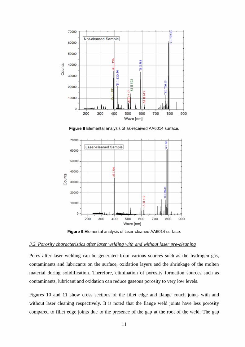
To observe the variation in surface chemistry before and after cleaning, laser induced
breakdown spectroscopy (LIBS) technique was used. Figures 8 and 9 show the surface
chemistry before and after cleaning respectively. From Figure 8, it is clear that as-received
surface contains Al, Zr, and Ti as it was coated with Zr & Ti. Figure 9 shows that Zr peak as
some of Ti peaks have disappeared in comparison with Figure 8. The high fluence of the pulsed
laser is able to remove about 19 microns of the surface of the aluminium alloy. This causes the
Ti/Zr coating that is adhered to the top of the surface layer to be removed during laser cleaning
since the Ti/Zr coating is only 3 nm in thickness, together with the lubricants. However, Figure
8 indicates that some titanium particles still existed on the laser-cleaned surface although other
Ti peaks in the range 400-600 nm have disappeared. It appears that laser-cleaning has removed
most of the coating and contaminants.
11
Figure 8 Elemental analysis of as-received AA6014 surface.
Figure 9 Elemental analysis of laser-cleaned AA6014 surface.
3.2. Porosity characteristics after laser welding with and without laser pre-cleaning
Pores after laser welding can be generated from various sources such as the hydrogen gas,
contaminants and lubricants on the surface, oxidation layers and the shrinkage of the molten
material during solidification. Therefore, elimination of porosity formation sources such as
contaminants, lubricant and oxidation can reduce gaseous porosity to very low levels.
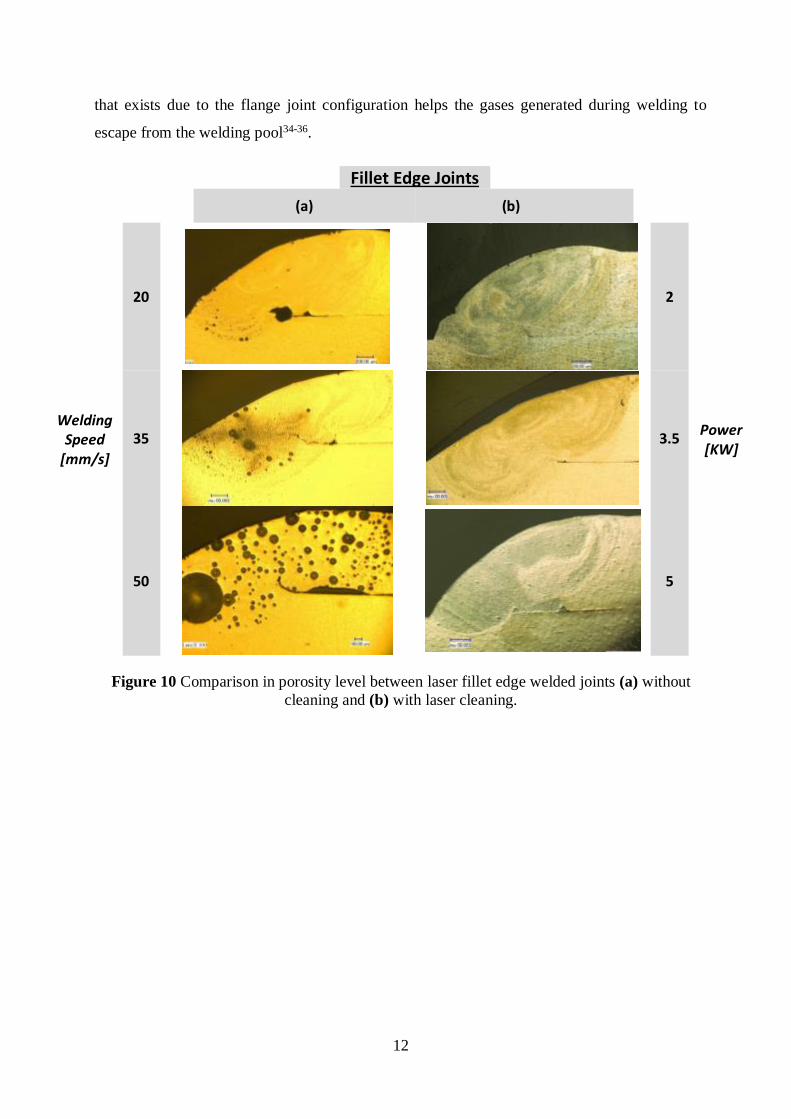
Figures 10 and 11 show cross sections of the fillet edge and flange couch joints with and
without laser cleaning respectively. It is noted that the flange weld joints have less porosity
compared to fillet edge joints due to the presence of the gap at the root of the weld. The gap
12
that exists due to the flange joint configuration helps the gases generated during welding to
escape from the welding pool34-36.
Fillet Edge Joints
(a) (b)
Welding Speed
[mm/s]
20
2
Power [KW]
35
3.5
50
5
Figure 10 Comparison in porosity level between laser fillet edge welded joints (a) without
cleaning and (b) with laser cleaning.

13
Flange couch joints
(a) (b)
Welding Speed
[mm/s]
20
2.4
Power [KW]
35
3.5
50
5
Figure 11 Comparison in porosity level in laser flange couch welded joints (a) without laser cleaning (b) with
laser cleaning.
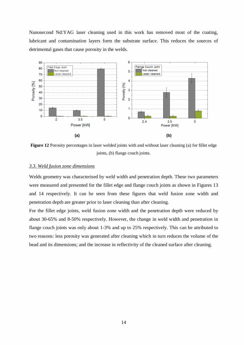
By comparing the cross sections of the as-received and cleaned samples (Figures 10 to 11), it
becomes evident that laser cleaning reduced porosity significantly in the weld zones. Porosity
percentages were specified as a ratio of the area occupied by the pores to the total area of the
weld. According to graphs shown in Figure 12, porosity was reduced after cleaning by about
95-98% for the fillet edge welds depending on welding parameters used in the process. Before
cleaning, porosity reached values between 10% and 80% of the cross section of the weld area,
while after cleaning it was reduced to less than 1% regardless welding parameters. For flange
couch joints, porosity was also decreased by 56% to 75% to reach values of 0.23-0.8% after
cleaning compared with 0.7-4.3% before laser cleaning depending on welding parameters.
14
Nanosecond Nd:YAG laser cleaning used in this work has removed most of the coating,
lubricant and contamination layers form the substrate surface. This reduces the sources of
detrimental gases that cause porosity in the welds.
(a) (b)
Figure 12 Porosity percentages in laser welded joints with and without laser cleaning (a) for fillet edge
joints, (b) flange couch joints.
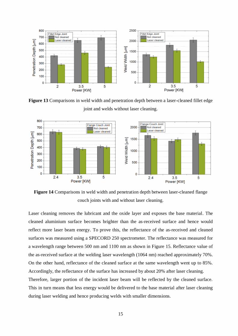
3.3. Weld fusion zone dimensions
Welds geometry was characterised by weld width and penetration depth. These two parameters
were measured and presented for the fillet edge and flange couch joints as shown in Figures 13
and 14 respectively. It can be seen from these figures that weld fusion zone width and
penetration depth are greater prior to laser cleaning than after cleaning.
For the fillet edge joints, weld fusion zone width and the penetration depth were reduced by
about 30-65% and 8-50% respectively. However, the change in weld width and penetration in
flange couch joints was only about 1-3% and up to 25% respectively. This can be attributed to
two reasons: less porosity was generated after cleaning which in turn reduces the volume of the
bead and its dimensions; and the increase in reflectivity of the cleaned surface after cleaning.
15
Figure 13 Comparisons in weld width and penetration depth between a laser-cleaned fillet edge
joint and welds without laser cleaning.
Figure 14 Comparisons in weld width and penetration depth between laser-cleaned flange
couch joints with and without laser cleaning.
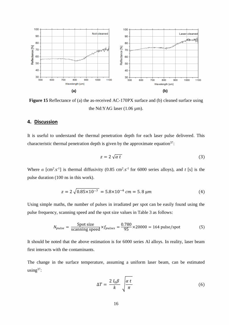
Laser cleaning removes the lubricant and the oxide layer and exposes the base material. The
cleaned aluminium surface becomes brighter than the as-received surface and hence would
reflect more laser beam energy. To prove this, the reflectance of the as-received and cleaned
surfaces was measured using a SPECORD 250 spectrometer. The reflectance was measured for
a wavelength range between 500 nm and 1100 nm as shown in Figure 15. Reflectance value of
the as-received surface at the welding laser wavelength (1064 nm) reached approximately 70%.
On the other hand, reflectance of the cleaned surface at the same wavelength went up to 85%.
Accordingly, the reflectance of the surface has increased by about 20% after laser cleaning.
Therefore, larger portion of the incident laser beam will be reflected by the cleaned surface.
This in turn means that less energy would be delivered to the base material after laser cleaning
during laser welding and hence producing welds with smaller dimensions.
16
(a) (b)
Figure 15 Reflectance of (a) the as-received AC-170PX surface and (b) cleaned surface using
the Nd:YAG laser (1.06 µm).
4. Discussion
It is useful to understand the thermal penetration depth for each laser pulse delivered. This
characteristic thermal penetration depth is given by the approximate equation37:
𝑧 = 2 √𝛼 𝑡 (3)
Where α [cm2.s-1] is thermal diffusivity (0.85 cm2.s-1 for 6000 series alloys), and t [s] is the
pulse duration (100 ns in this work).
𝑧 = 2 √0.85×10−7 = 5.8×10⁻⁴ 𝑐𝑚 = 5. 8 µ𝑚 (4)
Using simple maths, the number of pulses in irradiated per spot can be easily found using the
pulse frequency, scanning speed and the spot size values in Table 3 as follows:
𝑁𝑝𝑢𝑙𝑠𝑒 = Spot size
scanning speed×𝑓𝑝𝑢𝑙𝑠𝑒𝑠 =
0.78095
×20000 = 164 pulse/spot (5)
It should be noted that the above estimation is for 6000 series Al alloys. In reality, laser beam
first interacts with the contaminants.
The change in the surface temperature, assuming a uniform laser beam, can be estimated
using37:
∆𝑇 = 2 𝐼0𝛽
𝑘 √
𝛼 𝑡
𝜋 (6)
17
Where I0 is the power intensity, β = (1-R) and R is the surface reflectivity (70% as shown in
Figure 15(a)), k is thermal conductivity of AA6016 alloy (175 W/m.K as given in Table 3). For
one pulse and taking the reflectivity value from Figure15, equation (7) yields:
∆𝑇 = 2 ×6.27×1011 ×0.3
175 √
0.85 ×10−4 ×10−7
𝜋= 3236 °C (7)
If the room temperature is assumed to be 25oC, the surface temperature will be 3261°C which
is greater than the alloy boiling temperature (2520°C). It should be noted that this heat is
generated only by one pulse of 20,000 pulses in the second. The heat accumulated due to the
sequent pulses generates a very high temperature that results in vaporisation of the surface
material.
From the above calculation is can be seen that the surface temperature has reached above the
boiling point of the Al alloy. Thus the material removal mechanism would be based on
vaporisation.
Hydrogen solubility in aluminium differs significantly when aluminium is transformed from
solid to liquid. It was found that H2 solubility at melting temperature can reach up to 70 times
greater than the solid solubility for aluminium, while it is only 1.6 times greater than solid
solubility for iron38.
Hydrogen can be generated from the alloys’ material itself, moisture in the atmosphere and the
shielding gas, contaminants on the metal surface, moisture in shielding gas tubes, and oxide
layers. The following reaction explains how hydrogen can be generated from moisture38:
2Al + 3H2O Al2O3 + 3H2 (8)
Although laser cleaning helped to significantly reduce porosity in the studied Al alloys, there is
still a very small percentage of porosity in both types of welds after cleaning. This can be
attributed to many sources5, 39, 40:
1. Tiny layer of oxide that might have been formed after laser cleaning at fluence (6.27
J/cm2). This thin layer may generate a small percentage of porosity.
2. Ti particles that may still exist at the surface.
3. Hydrogen that already exists in the alloy composition.
4. Small amount of the shielding gas applied during welding process.
5. The keyhole collapse and instability during welding process.
18
It is worth mentioning that the automotive manufacturers set the maximum porosity level
allowed in aluminium welding to 10% of the weld cross section area. Moreover, the
companies require a minimum value of 25% of the sheet thickness for the penetration
depth, as well as a value of “t” (where t is the sheet thickness) for the weld width.
According to Figures 12-14, laser cleaning allowed the authors to meet the industrial
requirements in terms of porosity level and weld dimensions values and hence enabled
aluminium welding to be applied for car bodies welding.
5. Conclusions
According to the results reported in this work, the following conclusions can be drawn:
1. Laser cleaning was found to remove most of the lubricant and contaminants placed on
the surface of AC-170PX aluminium alloys. Moreover, laser cleaning removed about 19
microns from the substrate at the used cleaning parameters.
2. Depending on welding parameters, laser cleaning was found to achieve a significant
improvement of the weld quality by reducing porosity level to less than 1% for both
types of joints.
3. It is believed from this work that laser cleaning reduced porosity during the welding of
coated AC170 PX aluminium alloy due to the elimination of hydrogen and other gases
produced from coating, lubricant and the contaminants on the surface.
4. Weld dimensions were reduced when AC-170PX sheets were cleaned due to the
increase in reflectance of the surface after cleaning.
19
References
1. Feliu Jr. S., Pardo A., Merino M. C., Coy A. E., Viejo F., and A. R.: 'Correlation
between the surface chemistry and the atmospheric corrosion of AZ31, AZ80 and
AZ91D magnesium alloys', Appl Surf Science, 2009, 255(4102-8).
2. N. J. Cherepy, T. H. Shen, A. P. Esposito, and T. M. Tillotson: 'Characterization of an
effective cleaning procedure for aluminum alloys: surface enhanced Raman
spectroscopy and zeta potential analysis', Journal of Colloid and Interface Science,
2005, 282(1), 80-86.
3. Kersten H., Steffen H., and BehnkeJ.F.: 'Investigations on plasma-assisted surface
cleaning of aluminum contaminated with lubricants', Surface and Coatings Technology,
1996, 86-87, 762-768.
4. A. Haboudou, P. Peyre, A. B. Vannes, and G. Peix: 'Reduction of porosity content
generated during Nd:YAG laser welding of A356 and AA5083 aluminium alloys',
Materials Science and Engineering: A, 2003, 363(1-2), 40-52.
5. T. Dimogerontakis, R. Oltra, and O. Heintz: 'Thermal oxidation induced during laser
cleaning of an aluminium-magnesium alloy', Applied Physics A, 2005, 81(6), 1173-
1179.
6. Watkins K.G., Curran C., and Lee J.M.: 'Two new mechanisms for laser cleaning using
Nd:YAG sources', Journal of Cultural Heritage, 2003, 4, 59s-64s.
7. Yong-Feng L., Wen-Dong S., and Teck-Seng L.: 'Laser cleaning of micro-particles
from a solid surface --- theory and applications', Materials Chomiatry and Physics,
1998, 51, 181-185.
8. Tam A. C., Leung W. P., Zapka W., and Ziemlich W.: 'Laser cleaning techniques for
removal of surface particulates', Journal of Applied Physics, 1992, 71 (7), 3515.
9. Bäuerle D.: 'Laser Processing and Chemistry', 2000, Berlin Springer-Verlag.
10. Psyllaki P. and Oltra R.: 'Preliminary study on the laser cleaning of stainless steels after
high temperature oxidation', Mater Sci Eng, 2000, 282(1-2), 145.
11. M. W. Turner, P. L. Crouse, L. Li, and A. J. E. Smith: 'Investigation into CO2 laser
cleaning of titanium alloys for gas-turbine component manufacture', Applied Surface
Science, 2006, 252(13), 4798-4802.
12. Gruhn W., Kityk I.V., and Benet S.: 'Photoinduced optical second harmonic generation
in Fe–Co metallic spin glasses', Materials Letters, 2002, 55 158-164.
13. M. W. Turner, P. L. Crouse, and L. Li: 'Comparison of mechanisms and effects of
Nd:YAG and CO2 laser cleaning of titanium alloys', Applied Surface Science, 2006,
252(13), 4792-4797.
14. Turner M. W. , Schmidt M. J. J. , and Li L. : 'Preliminary study into the effects of YAG
laser processing of titanium 6Al–4V alloy for potential aerospace component cleaning
application', Applied Surface Science, 2005, 247(1-4), 623-630.
15. M. W. Turner, P. L. Crouse, and L. Li: 'Comparative interaction mechanisms for
different laser systems with selected materials on titanium alloys', Applied Surface
Science, 2007, 253(19), 7992-7997.
16. Rechner R. , Jansen I. , and Beyer E. : 'Influence on the strength and aging resistance of
aluminium joints by laser pre-treatment and surface modification', International Journal
of Adhesion and Adhesives, 2010, 30(7), 595-601.
17. Yue L., Wang Z., and Li L.: 'Material morphological characteristics in laser ablation of
alpha case from titanium alloy', Applied Surface Science, 2012, 258(20), 8065-8071.
18. Marimuthu S, Kamara A M, Whitehead D, Mativenga P T, and Li L.: 'Laser Removal
of TiN Coatings from WC Micro-tools and In-process Monitoring', Optics & Laser
Technology, 2010, 42(8), 1233-1239.
20
19. Marimuthu S. , Mhich A. , Molchan I. S. , Whitehead D. , Wang Z. B. , Mativenga P.,
Li L. , Liu Z. , Grafton-Reed C. , Cheetham S. , and Dilworth S. : 'Numerical
Simulation of Excimer Laser Cleaning of Film and Particle Contaminants', Journal of
Heat Transfer, 2013, 135(12), 121301-121301.
20. P. Zhang, Q. Su, and D. Luan: 'Twist Rotation Deformation of Titanium Sheet Metal in
Laser Curve Bending Based on Finite Element Analysis', 2014, 277, 921-928.
21. Delaporte P. , Gastaud M. , Marine W. , Sentis M. , Uteza O. , Thouvenot P. , Alcaraz J.
L. , Samedy J. M. Le , and Blin D. : 'Dry excimer laser cleaning applied to nuclear
decontamination', Applied Surface Science, 2003, 208-209, 298-305.
22. Allen S.D. , Miller A.S. , and Lee S.J.: 'laser cleaning of critical surface', Materials
Chomiatry and Physics, 1998, 51, 181-185.
23. Hallo L. , Riou O. , Stenz C. , and Tikhonchuk V. T.: 'Infrared emissivity studies of
melting thresholds and structural changes of aluminium and copper samples heated by
femtosecond laser pulses', Journal of Physics D: Applied Physics, 2006, 39(24), 5272-
5279.
24. Meja P. , Autric M. , Delaporte P. , and Alloncle P. : 'Dry laser cleaning of anodized
aluminium', Appl. Phys. A 69 [Suppl.], 1999, S343-S346.
25. Vilar R. , M. S. F. Lima, R. Riva, A. C. de Oliveira, G. R. Siqueira, O. Conde, M.
Fajardo, L. O. Silva, M. Pires, and A. Utkin: 'Laser beam welding aerospace aluminum
using fiber lasers', 2008, 7131, 713128-713128-713124.
26. El-Batahgy A. and Kutsuna M. : 'Laser Beam Welding of AA5052, AA5083, and
AA6061 Aluminum Alloys', Research Letters in Materials Science, 2009, 2009, 1-9.
27. Sánchez-Amaya J. M. , Delgado T. , De Damborenea J. J. , Lopez V. , and Botana F. J. :
'Laser welding of AA 5083 samples by high power diode laser', Science Technology of
Welding and Joining, 2009, 14(1), 78-86.
28. Anon: 'BS EN 10002-1:2001 - Tensile testing of metallic materials. Method of test at
ambient temperature', 2001.
29. Anon: 'AC-170Px Aluminium Technical Specifications', (ed. e. N. D. GmbH), 2011,
Stuttgart, Germany.
30. Anon: 'FONTARGEN A 405 M Aluminium-Silicon Wire Specifications', (ed. F. ed. F.
BRAZING), Germany.
31. Narikiyo T., Miura H., Fujinaga S., and Ohmori A.: 'Plume aspects and penetration
shape with inclined YAG laser beams', Opt Lett, 1996 21(19), 1562-1563.
32. Anon: 'cleanLASER CL600 Technical specifications', (ed. T. S. E. GmbH), Germany.
33. Anon: 'Trumpf Lasers', [viewed September 2013; Available from: http://www.trumpf-
laser.com/en/products/solid-state-lasers/disk-lasers/trudisk.html.
34. Pan Y. and Richardson I.M.: 'Study of laser welding of zinc coated steel sheets in
overlap configuration', 11th NOLAMP Conference in Laser Processing ofMaterials,
Lappeenranta 2007.
35. Mäkikangas J., Mäntyjärvi K., Keskitalo M., Karjalainen J.A., Niemela J., and O. J.:
'Laser welding of coated sheet metal constructions', 11th NOLAMP Conference in
Laser Processing of Materials, Lappeenranta 2007.
36. Gualini M.M.S.: 'Laser welding of zinc coated steel sheets. An old problem with a
possible solution', 20th International Congress on Applications of Lasers & Electro–
Optics, ICALEO, Jacksonville-Florida, 2001, 511.
37. Steen W. M. and Mazumder J. : 'Laser Material Processing', 2010, Springer.
38. Anon: 'ASM Handbook, Metallography and microstructures', 2004, American Society
for Metals (ASM).
39. Couso E. V. and G. J. V.: 'Laser Beam Welding and Automotive Engineering',
Advanced Structural Materials, 2012, 8, 59-84.
21
40. E. Vaamonde Couso and J. Vázquez Gómez: 'Laser Beam Welding and Automotive
Engineering', 2010, 8, 59-84.