Embed Size (px)
Citation preview
1
Article type: Full Paper
Manuscript ID: ic-2015-026878.R1
Title: Vanadium oxyfluorides/few layer graphene composite as high performance
cathode material for lithium batteries
Musa Ali Cambaz 1, B. P. Vinayan
1, Oliver Clemens
2,3, Anji Reddy Munnangi
1, Venkata Sai
Kiran Chakravadhanula 1, Christian Kübler
1,2 and Maximilian Fichtner
1,2,*
1Helmholtz Institute Ulm for Electrochemical Energy Storage (HIU), Helmholtzstr. 11, 89081
Ulm, Germany
2Institute of Nanotechnology, Karlsruhe Institute of Technology (KIT), P.O. Box 3640, 76021
Karlsruhe, Germany
3Technische Universität Darmstadt, Joint Research Laboratory Nanomaterials, Jovanka-
Bontschits-Straße 2, 64287 Darmstadt, Germany
E-mail: [email protected]
Keywords: metal oxyfluorides, lithium batteries, few layer graphene, high energy density,
structural rearrangement
2
Abstract
Metal oxyfluoride compounds are gathering significant interest as cathode materials for
lithium ion batteries at the moment, due to their high theoretical capacity and resulting high
energy density. In this regard, a new and direct approach is presented to synthesize vanadium
oxyfluorides (VO2F), which is phase pure. The structure of VO2F was identified by Rietveld
refinement of the powder XRD pattern. It crystallizes in perovskite type structure with a
disorder of oxide and fluoride ions. The as synthesized VO2F was tested as a cathode material
for lithium batteries after being surface coated with a few layer graphene. The VO2F delivered
a first discharge capacity of 254 mAh g-1
and a reversible capacity of 208 mAh g-1
at a rate of
C/20 for the first 20 cycles with an average discharge voltage of 2.84 V, yielding an energy
density of 591 Wh kg-1
. Improved rate capability, which outperforms the previous report, has
been achieved showing discharge capacity of 150 mAhg-1
for 1 C. The structural changes
during lithium insertion and extraction were monitored by ex-situ XRD analysis of the
electrodes discharged and charged to various stages. Lithium insertion results in irreversible
structural change of the anion lattice from ¾ cubic close packing to a hexagonal close packing
to accommodate the inserted lithium ions, but keeping the overall space-group symmetry. For
the first time we revealed a structural change for the ReO3 type structure of as-prepared VO2F
to a RhF3 structure after lithiation /delithiation, with structural changes that have not yet been
observed in previous reports. Furthermore, the new synthetic approach described here would
be a platform for the synthesis of new oxyfluoride compounds.
3
1. Introduction
In order to meet the various requirements for current and future developments of lithium ion
batteries (LIBs), performance improvements are necessary and the exploitation of novel types
of electrode materials with high energy density is therefore mandatory.1–3
The voltage, and
energy density related thereto, of LIBs is directly linked to the electronic and the crystal
structure, which is reflected in the bonding properties. In this context, metal oxides have
attracted the most attention due to their versatile and rich redox chemistry, which is governed
by the bonding nature of the metal to ligand (oxygen) bond (M-O bond).4–8
An appealing
alternative are metal fluorides, in which the strong ionic character of the M - F bond offers the
possibility of getting high redox potentials. However, pure metal fluorides are insulating, and
exhibit sluggish kinetics and low efficiency.9 The tailoring of the electrochemistry by partially
replacing the oxygen-ions (O2-
) by higher electronegative fluoride-ions (F-) are promising
approaches for designing new electrode materials.10
Mixed-anion materials like oxyfluorides
represent a good compromise between the aforementioned chemistries and can lead to high
redox potentials, lower polarization and good cyclic stability.11–13
After the introduction of a new type of disordered rock salt type intercalation compounds
Li2MO2F (M=V, Cr)14,15
as cathode material for LIBs, oxyfluoride chemistry has attracted a
lot of attention. Furthermore, perovskite type MO3-xFx (M = Ti, Ta, Mo, W, Nb) 16–18
transition metal oxyfluorides crystallizing in the cubic ReO3 structure type have been known
to reversibly insert lithium. Their structure can be derived from the well-known cubic ABO3
perovskite structure leaving all the A-sites vacant. The empty A-site substructure serves as a
3-dimensional sublattice, accessible for the intercalation of guest cations19
. The first report
for the intercalation of lithium into NbO2F was published by Chowdari’s group17
, with an
4
reported capacity of ~180 mAh g-1
, corresponding to the insertion of ~ 1.0 Li per NbO2F.
However, lithium insertion into ReO3 type materials is accompanied by structural
rearrangements along with a change in the Li-ion bonding and therefore in the
electrochemistry.20
Recent a report on the synthesis of VO2F obtained by a solid state reaction
using high pressures and temperatures of 4 GPa and 800°C appeared.21
The reported VO2F
had 3 wt% of unknown Impurities and is showing a first discharge capacity of 250 mAh/g in
the cycling range of 2.2 V-3.9 V with severe capacity fading for prolonged cycling and kinetic
limitations for higher current densities. VO2F, due to its low weight and higher redox
potential, offers a higher theoretical capacity of 262 mAh g-1
(with respect to the intercalation
of one Li per VO2F unit) and therefore higher gravimetric energy density compared to its
analogues. In addition, it is observed that the electrochemical performances of cathode
materials can significantly depend upon the conductive surface coating of active materials.
Among different conductive coating materials, graphene based nanostructures are very
promising due to their high surface area, excellent electronic conductivity and high
mechanical stability.22–24
Herein, we show a new way for the synthesis of phase pure vanadium dioxyfluoride (VO2F)
obtained by an one-step mechano-chemical approach using V2O5 and VOF3 as the starting
precursors at room temperature. VO2F particles were further coated with conductive few layer
graphene (FLG). The resulting VO2F-FLG composite serves from the electrochemical point
of view as cathode material showing a first discharge capacity of 254 mAh g-1
and a
reversible capacity of 208 mAh g-1
. Furthermore, we investigate the structural rearrangement,
occuring during lithiation/de-lithiation by ex-situ XRD analysis and unveil the relationship to
the RhF3 structure, which has not been observed before for VO2F before.
2. Experimental Section
5
Materials Preparation: The vanadium dioxyfluoride was synthesized by high-energy milling
of stoichiometric amounts of (1.1822 g; 0.0065 mol) V2O5 and (0.8056 g; 0.0065 mol) VOF3
for 20h using a Fritsch P6 planetary ball mill with 80 mL silicon nitride vial and silicon
nitride balls with a ball to powder ratio 15:1. 1 All synthesis steps were carried out under inert
gas atmosphere. Few layer graphene was synthesized by the thermal exfoliation of graphite
oxide at 1050 °C in argon atmosphere. Where graphite oxide was prepared by Hummer’s
method.25
The obtained VO2F was milled with 20 wt. % few layer graphene (FLG).
Materials Characterization: Powder XRD data were collected on a STOE Stadi P
diffractometer with Mo Kα1 (λ = 0.7093 Å) using Debye-Scherrer geometry. The powder
samples were sealed in quartz capillary (0.5mm in diameter) under an argon atmosphere. The
scanning electron microscope (SEM) and energy dispersive X-ray spectroscopy (EDS) were
carried out using the instrument LEO GEMINI 1550 VP equipped with Silicon Drift Detector
(OXFORD Instruments).
Transmission electron microscopy (TEM) characterization of the nanocomposite was carried
out using an aberration corrected FEI Titan 80-300 operated at 300 kV equipped with a Gatan
imaging filter (Tridiem 863). For (S)-TEM measurements, samples were prepared by
dispersing a small amount of powder directly onto holey carbon Au grids (Quantifoil GmbH).
EDX-EELS Elemental mapping of the sample was performed in the scanning transmission
electron microscopy mode (STEM- HAADF) with drift correction.
Electrochemical Measurement: Electrochemical tests were carried out in Swagelok-type cell
versus lithium. Electrode slurries were made of 90 wt% composite and 10 wt%
polyviniylidene difluoride (PVDF) binder with N-methyl-2-pyrrolidone (NMP) as solvent.
The mixed slurry was coated on an aluminum foil by doctor blade technique and dried at
120°C for 12h under vacuum. Each working electrode (12 mm diameter) contained
6
approximately 3 mg of active material and Li foil was used as counter electrode. LP30 from
BASF (ethylene carbonate/ dimethyl carbonate, 1:1 volume ratio with 1M LiPF6) was used as
electrolyte. Cyclic voltammetry (CV) experiments for the cells have been carried out from
2.1 to 4.3 V at a scan rate of 0.1 mV s-1
using a Bio-Logic VMP-3 potentiostat. Temperature
controlled galvanostatic charge-discharge experiments were conducted using Arbin
electrochemical workstation at the room temperature in the potential range 2.1 to 4.3 V.
3. Result and Discussion
Material Characterization
The synthesis methodology followed for vanadium oxyfluoride/few layer graphene
(VO2F/FLG) nanocomposites includes two steps: i) synthesis of pure phase of VO2F by one-
step mechano-chemical approach, (ii) surface coating of VO2F with a conductive few layer
graphene. In the first step, the VO2F was synthesized by high-energy milling of appropriate
stoichiometric amounts of V2O5 and VOF3 for 20h and the formation of the pure phase of
VO2F was confirmed by powder X-ray diffraction (see the further discussion below). In the
second step, few layer graphene coating on VO2F particles was carried out by milling
approach and confirmed by transmission electron microscopy (see the discussion below). The
final weight ratio of VO2F to FLG was 5:1 in the composite. It was observed that, as prepared
VO2F/FLG nanocomposite is stable in air. (See the experimental section for more details)
7
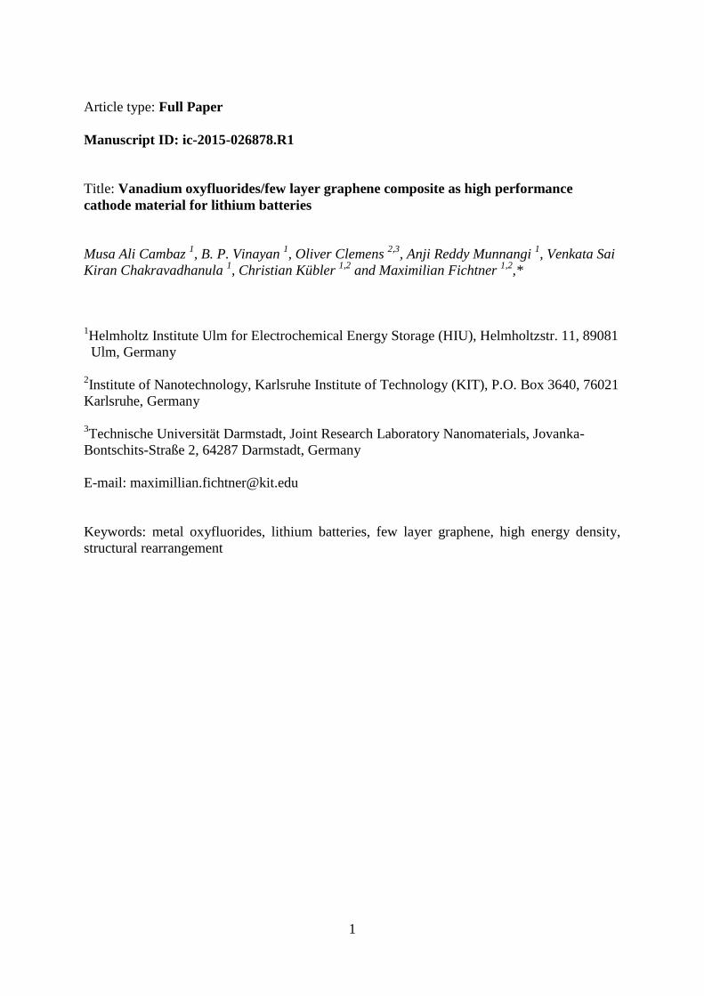
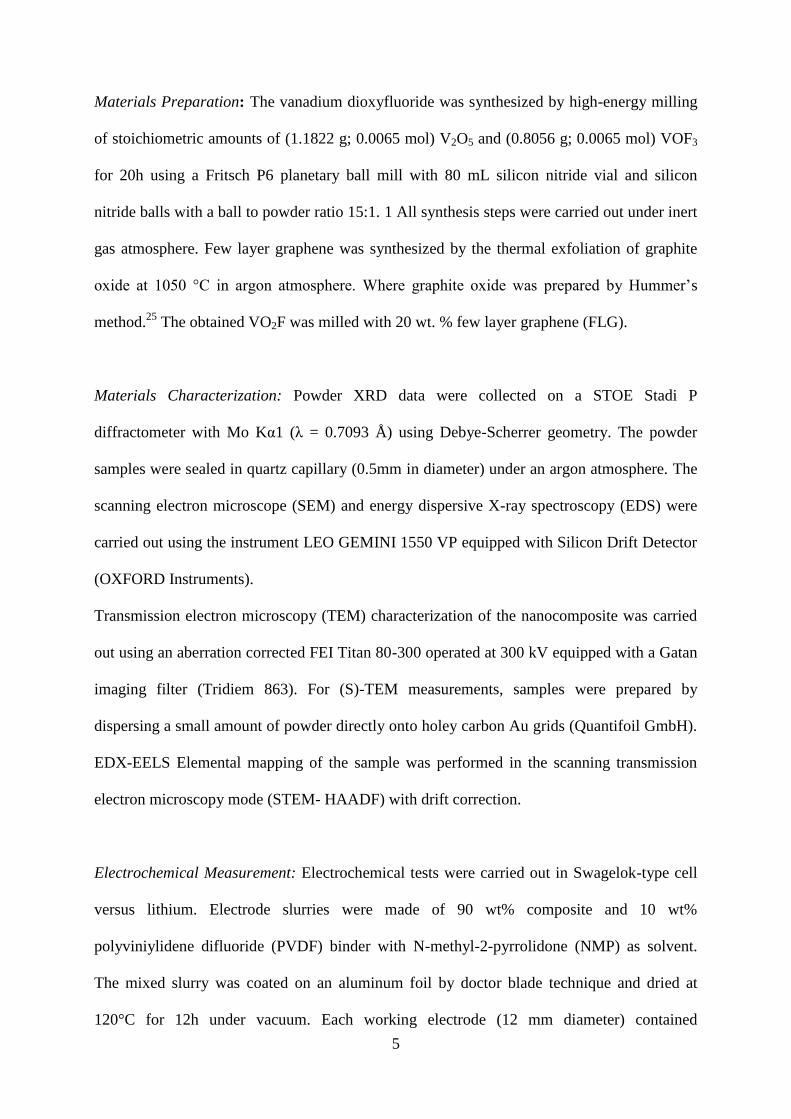
Figure 1. Rietveld refined XRD pattern of VO2F. Inset shows the crystal structure of VO2F.
The structure of VO2F was determined by powder X-ray diffraction (XRD). A single phase
with ReO3 related structure was detected without the presence of impurity phases. All the
reflections could be indexed using a trigonally distorted ReO3 type phase with space group R-
3c, which was confirmed using the Pawley method. The validity of this symmetry is clearly
indicated and well supported by the appearance of the (1 1 3)R-3c superstructure reflection as
well as the splitting pattern of the main reflections in comparison to the cubic aristotype
structure with space group Pm-3m. This symmetry was also found for the high pressure
modification of NbO2F.26
Full structural analysis was then performed using a modified
structural model of NbO2F26
as starting model, refining the structural parameters. This
resulted in an excellent fit of the pattern (see Figure 1). The refined structural data and a
drawing of the crystal structure is shown in Figure 1.
8
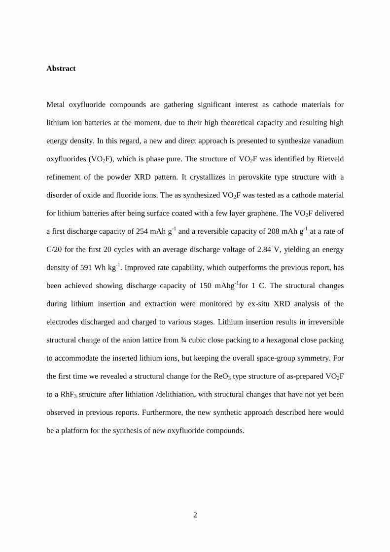
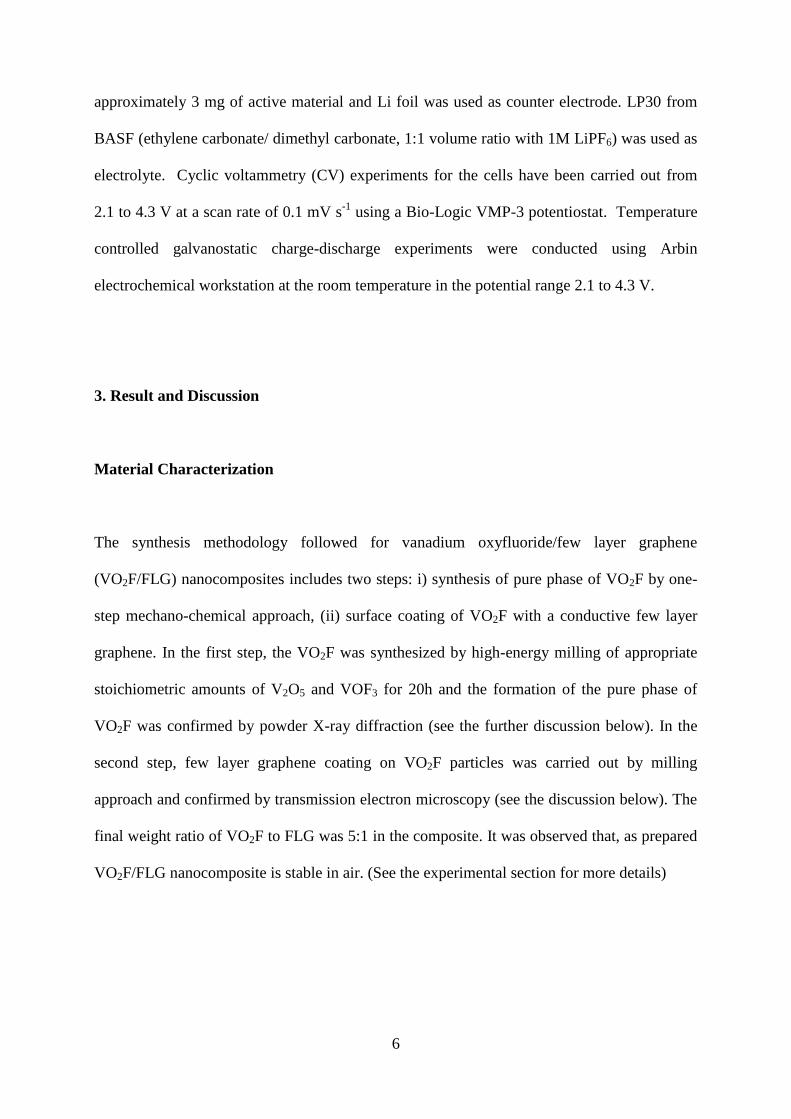
Figure 2. (a) Bright-field TEM (BF-TEM) images of VO2F/FLG sample. (b) Selected area
diffraction (SAED) pattern of the BF-TEM. (c) Dark-field TEM (DF-TEM) by using the
10µm aperture on the SAED reflection corresponding to 3.67 Å (012). (d) STEM-HAADF
image of VO2F/FLG sample. (e, f) High-resolution TEM micrograph of VO2F/FLG sample
with the corresponding FFT.
9
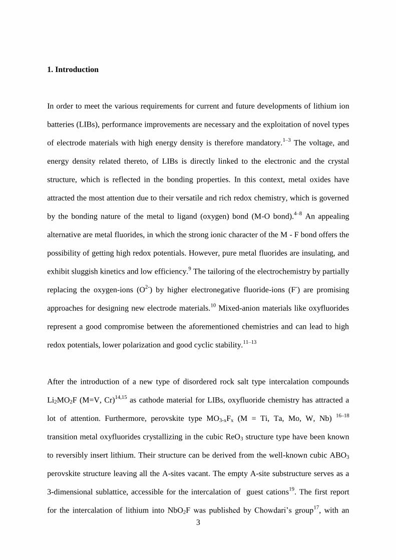
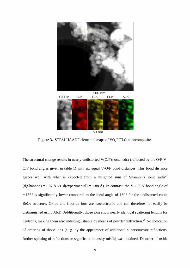
Figure 3. STEM-HAADF elemental maps of VO2F/FLG nanocomposite.
The structural change results in nearly undistorted V(O/F)6 octahedra (reflected by the O/F-V-
O/F bond angles given in table 1) with six equal V-O/F bond distances. This bond distance
agrees well with what is expected from a weighted sum of Shannon’s ionic radii27
(d(Shannon) = 1.87 Å vs. d(experimental) = 1.88 Å). In contrast, the V-O/F-V bond angle of
~ 156° is significantly lower compared to the ideal angle of 180° for the undistorted cubic
ReO3 structure. Oxide and fluoride ions are isoelectronic and can therefore not easily be
distinguished using XRD. Additionally, those ions show nearly identical scattering lengths for
neutrons, making them also indistinguishable by means of powder diffraction.28
No indication
of ordering of those ions (e. g. by the appearance of additional superstructure reflections,
further splitting of reflections or significant intensity misfit) was obtained. Disorder of oxide
10
and fluoride ions is a well-known phenomenon observed for many perovskite-type transition
metal oxyfluorides 29–35
which can be derived from a ccp stacking of AX3 layers. In contrast,
ordering of fluoride ions was found for many hexagonal type perovskite compounds36–39
.
Nevertheless, the structural distortion found for VO2F can be well understood in terms that the
distortion results in a lowering of the size of the empty A-site cavities, leading to an overall
decrease of cell volume and stabilization of the structural arrangement (see also discussion of
lithiated compounds later in this article).
Transmission electron microscope (TEM) studies were carried out to investigate the in-depth
morphology of the VO2F/FLG (Figure 2). Bright-field TEM (BF-TEM) imaging (Figure 2a)
of the material illustrate the composite nature of the sample. The dark contrast of VO2F
particles can be seen from the BF-TEM image and the corresponding selected area diffraction
(SAED) pattern were given in Figure 2b. The d-values measured from the indexed SAED
pattern correspond to the metrics from R-3c trigonal system VO2F 3.67 Å (012), 2.62 Å (104),
2.56 Å (110), 2.2 Å (113), respectively from the center of the SAED pattern. Dark-field
TEM (DF-TEM) by using the 10 µm aperture on the SAED reflection corresponding to 3.67
Å (012), depicts the regions of VO2F in the DF-TEM image (Figure 2c). From the BF-TEM
image, it is difficult to distinguish between carbon and VO2F very clearly, where STEM-
HAADF image (Figure 2d) shows a clear Z-contrast. Figure 2(e, f) shows the high resolution
TEM micrograph along with the corresponding fast Fourier transformation (FFT). The d-
values from the FFT (Figure 2f) correspond to aforementioned metrics from the SAED pattern
(Figure 2b) and XRD data. The presence of brighter and fainter rings in the diffraction
patterns (Figure 2(b, f)), indicates the polycrystalline to partly amorphous nature of the
particles and corresponds to the broadened reflections observed in the XRD pattern.
Furthermore, the high-resolution TEM micrograph (Figure 2e) shows that VO2F particles
were covered with few layer graphene. STEM-HAADF elemental maps of the corresponding
11
elements though EDX detector was shown in Figure 3 where the V-K, O-K and F-K maps
overlap with each other well. From the C-K map, it appears as if the VO2F is embedded in a
few layer graphene matrix. XPS measurements of the as synthesized sample were carried out,
and confirm the V5+
oxidation state (Figure S1 supporting information). From the diffraction
data, no significant deviation from an overall composition of VX3 is noticed. This in
combination with XPS measurement supports the assumption of an overall composition of
VO2F.
Electrochemical study
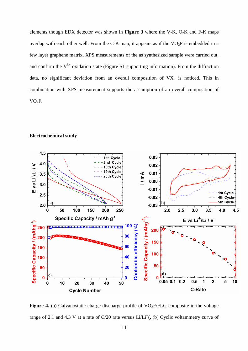
Figure 4. (a) Galvanostatic charge discharge profile of VO2F/FLG composite in the voltage
range of 2.1 and 4.3 V at a rate of C/20 rate versus Li/Li+(, (b) Cyclic voltammetry curve of
12
VO2F/FLG composite at a scan rate with of 0.1 mVs-1
(c) Cycling stability for C/20 rate
between 2.1 and 4.3 V versus Li/Li+(d) Discharge capacities of VO2F/FLG composite at
different rates between the voltage range of 2.1 and 4.3 V versus Li/Li+.
Figure 4 shows typical galvanostatic discharge and charge profiles of VO2F/FLG composite
versus lithium obtained at C/20 rate (assuming the aforementioned theoretical capacity of 262
mAh g-1
) within the voltage range of 2.1V - 4.3V. During the first discharge, which
corresponds to the insertion of lithium into the VO2F, no plateau is visible, suggesting a solid
solution system. The upcoming second cycle shows reduced polarization compared to the first
one. It is interesting to note is the gradual upshift of the discharge and charge voltages, which
were found to superimpose for prolonged cycling.
Figure 4 b depicts the corresponding cyclic voltammetry curves for the VO2F/FLG composite.
In the CV, for the first cathodic process broad peaks were observed at ~ 2.7 V and ~ 2.15 V,
which could be attributed to the Li+ insertion into the crystal structure and the structural
rearrangement. A broad anodic peak appears at 3.1 V, which can be assigned to the lithium
deintercalation. When cycling continues the shape of the cyclic voltammetry curves change
completely and CV curves tend to overlap, associated with a lower polarization. These
findings suggest the occurrence of some irreversible processes in the initial cycles. The broad
nature of the peaks for the initial cycles suggest indiscrete Li sites, which possibly can be
attributed to disordered or amorphous phases of the VO2F/FLG composite supported by the
finding of rings in the SAED pattern (Figure 2 f) and the broadened peaks as shown in the
XRD patterns. For mechano-synthesized perovskite type40
and nanocrystalline oxide41
compounds an amorphous shell has been reported.
13
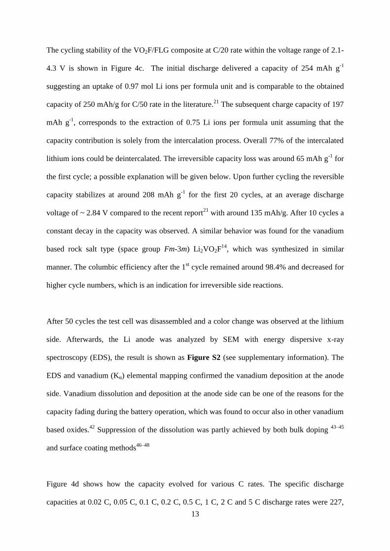
The cycling stability of the VO2F/FLG composite at C/20 rate within the voltage range of 2.1-
4.3 V is shown in Figure 4c. The initial discharge delivered a capacity of 254 mAh g-1
suggesting an uptake of 0.97 mol Li ions per formula unit and is comparable to the obtained
capacity of 250 mAh/g for C/50 rate in the literature.21
The subsequent charge capacity of 197
mAh g-1
, corresponds to the extraction of 0.75 Li ions per formula unit assuming that the
capacity contribution is solely from the intercalation process. Overall 77% of the intercalated
lithium ions could be deintercalated. The irreversible capacity loss was around 65 mAh g-1
for
the first cycle; a possible explanation will be given below. Upon further cycling the reversible
capacity stabilizes at around 208 mAh g-1
for the first 20 cycles, at an average discharge
voltage of ~ 2.84 V compared to the recent report21
with around 135 mAh/g. After 10 cycles a
constant decay in the capacity was observed. A similar behavior was found for the vanadium
based rock salt type (space group Fm-3m) Li2VO2F14
, which was synthesized in similar
manner. The columbic efficiency after the 1st cycle remained around 98.4% and decreased for
higher cycle numbers, which is an indication for irreversible side reactions.
After 50 cycles the test cell was disassembled and a color change was observed at the lithium
side. Afterwards, the Li anode was analyzed by SEM with energy dispersive x-ray
spectroscopy (EDS), the result is shown as Figure S2 (see supplementary information). The
EDS and vanadium (Kα) elemental mapping confirmed the vanadium deposition at the anode
side. Vanadium dissolution and deposition at the anode side can be one of the reasons for the
capacity fading during the battery operation, which was found to occur also in other vanadium
based oxides.42
Suppression of the dissolution was partly achieved by both bulk doping 43–45
and surface coating methods46–48
Figure 4d shows how the capacity evolved for various C rates. The specific discharge
capacities at 0.02 C, 0.05 C, 0.1 C, 0.2 C, 0.5 C, 1 C, 2 C and 5 C discharge rates were 227,
14
206,192, 180, 162, 150, 105, 80 mAh g-1
respectively. We are showing improved capacity
retention compared to the previous report21
, which is showing a discharge capacities of
around 240 mAh/g for 0.02C and around 50 mAh/g for 1 C. An increase in the current density
goes along with a decrease in capacity especially for higher rates. This finding indicates
kinetic limitations, which could be attributed to the low ionic or electronic conductivity. This
agrees well with the observations made on electrode of VO2F prepared without any carbon
coating, which did not show any noticeable electrochemical activity. For reasons of
comparability and in order to verify the impact of FLG coating, VO2F was coated with a
different carbon material (Super C65 carbon black) by a similar approach. For the latter a
lower capacity retention and poorer c-rate capability (Figure S3 see supplementary) was
found.
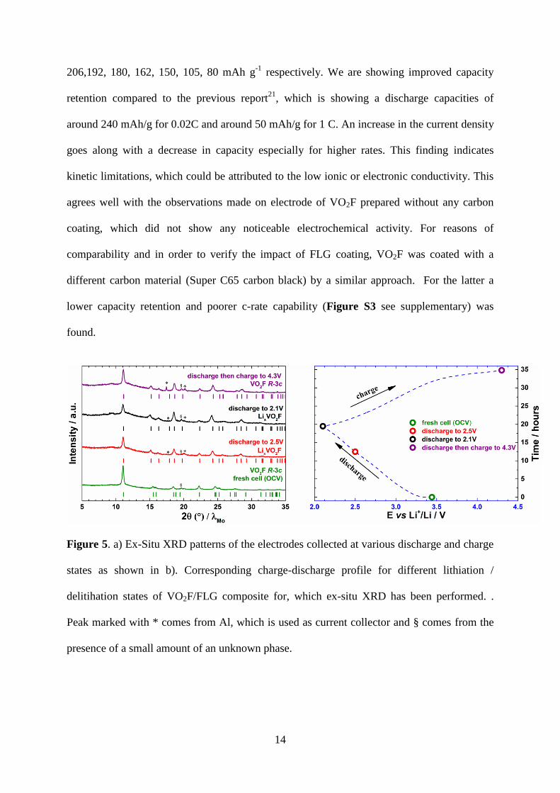
Figure 5. a) Ex-Situ XRD patterns of the electrodes collected at various discharge and charge
states as shown in b). Corresponding charge-discharge profile for different lithiation /
delitihation states of VO2F/FLG composite for, which ex-situ XRD has been performed. .
Peak marked with * comes from Al, which is used as current collector and § comes from the
presence of a small amount of an unknown phase.
15
Ex-situ XRD patterns were collected on the discharged and charged electrodes in order to
investigate the structural changes occurring during lithium insertion and extraction. Figure 5a
shows the XRD patterns of the electrodes collected at different discharge and charge states as
represented in Figure 5b as prepared discharged to 2.5 V, 2.1 V and recharged to 4.3 V.
Structural parameters obtained from Rietveld analysis of different products were summarized
in Table 1.
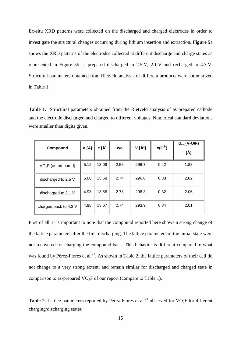
Table 1. Structural parameters obtained from the Rietveld analysis of as prepared cathode
and the electrode discharged and charged to different voltages. Numerical standard deviations
were smaller than digits given.
Compound a [Å] c [Å] c/a V [ų] x(O2-
) davg(V-O/F)
[Å]
VO2F (as-prepared) 5.12 13.09 2.56 296.7 0.42 1.88
discharged to 2.5 V 5.00 13.68 2.74 296.0 0.33 2.02
discharged to 2.1 V 4.98 13.88 2.78 298.3 0.32 2.06
charged back to 4.3 V 4.98 13.67 2.74 293.9 0.34 2.01
First of all, it is important to note that the compound reported here shows a strong change of
the lattice parameters after the first discharging. The lattice parameters of the initial state were
not recovered for charging the compound back. This behavior is different compared to what
was found by Pérez-Flores et al.21
. As shown in Table 2, the lattice parameters of their cell do
not change to a very strong extent, and remain similar for discharged and charged state in
comparison to as-prepared VO2F of our report (compare to Table 1).
Table 2. Lattice parameters reported by Pérez-Flores et al.21
observed for VO2F for different
charging/discharging states
16
Compound a [Å] c [Å] V [ų] c/a
VO2F (as-prepared) 5.1210(4) 13.073(2) 296.9(1) 2.55
Discharged 2.3 V 5.1162(9) 13.051(2) 295.9(1) 2.55
Charged 3.9 V 5.1190(4) 13.078(2) 296.8(1) 2.55
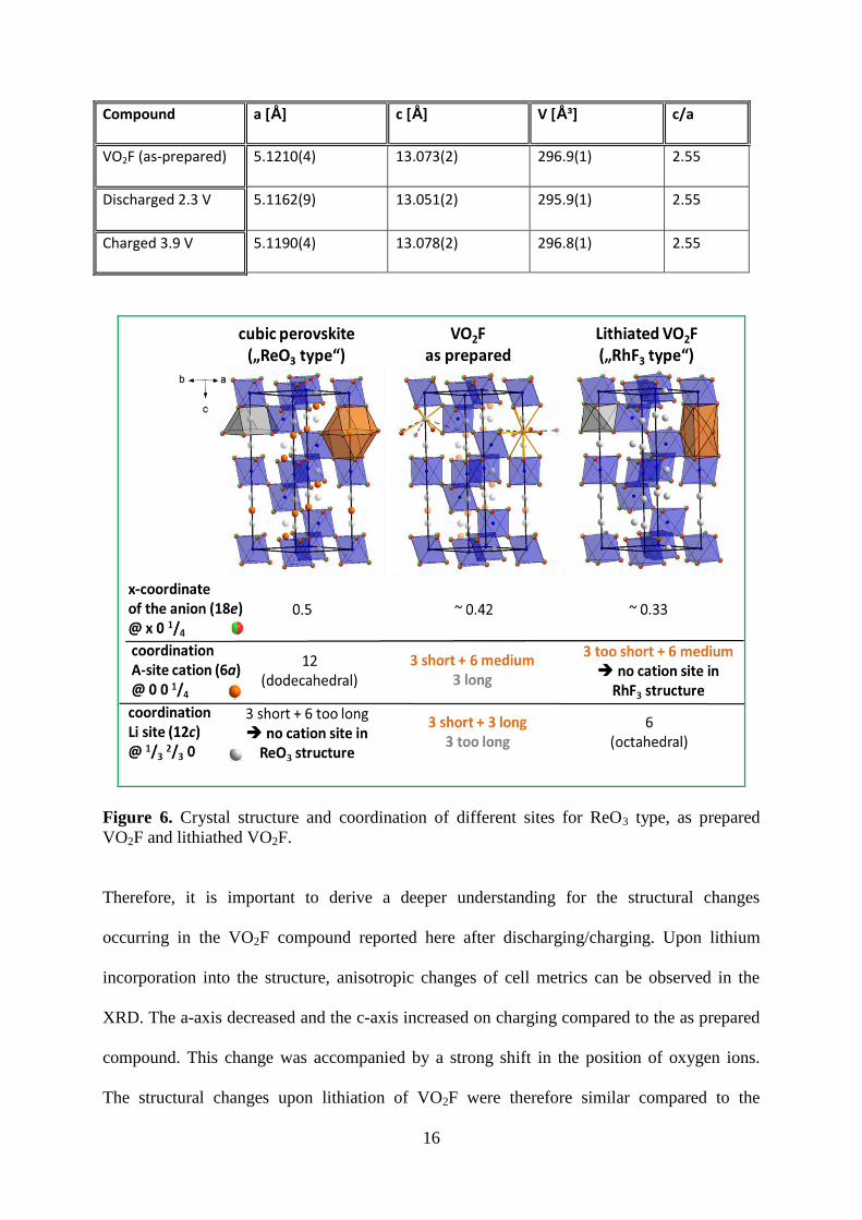
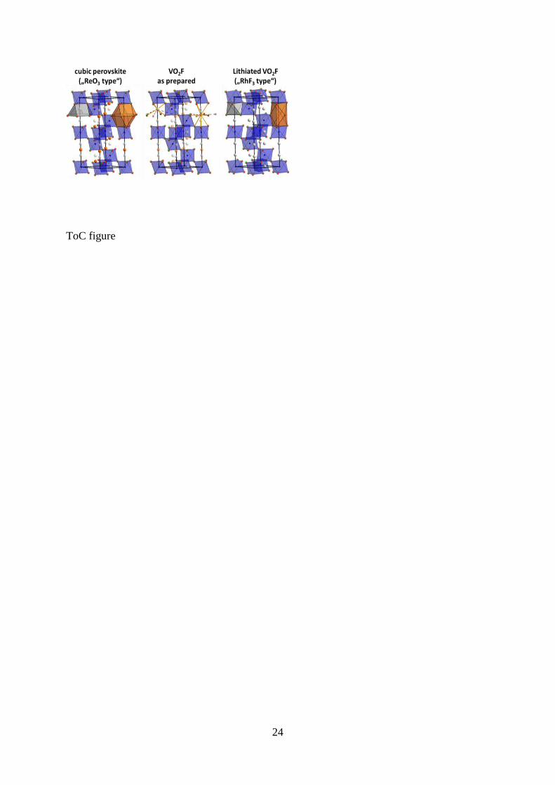
Figure 6. Crystal structure and coordination of different sites for ReO3 type, as prepared
VO2F and lithiathed VO2F.
Therefore, it is important to derive a deeper understanding for the structural changes
occurring in the VO2F compound reported here after discharging/charging. Upon lithium
incorporation into the structure, anisotropic changes of cell metrics can be observed in the
XRD. The a-axis decreased and the c-axis increased on charging compared to the as prepared
compound. This change was accompanied by a strong shift in the position of oxygen ions.
The structural changes upon lithiation of VO2F were therefore similar compared to the
17
lithiation of ReO319
, which were shown in figure 6 and could be summarized as follows: the
structure of VO2F can be understood in terms of distorted cubic perovskite structure (ABX3)
with an empty A-site sub lattice. For a pseudo cubic setting of the structure, the x coordinate
of the anion site must equal to ½ and the length of the c-axis must be exactly equal to 60.5
* a
~ 2.45 * a. For pure VO2F, the structure is already distorted to some degree (x(O2-
) ~ 0.42,
c/a ~ 2.56). Upon lithium incorporation, we found that the c/a ratio further deviates from a
value of 60.5
(2.74 – 2.78), and that the position of the oxygen ion approaches a value of 1/3.
This shift of the oxygen ion results in a strong structural change, which has been described as
a change from a ¾ cubic close packing (ReO3 type structure) of anions to a hexagonal close
packing of anions with 1/3 occupancy of the octahedral sites (RhF3 type structure)49
. The
structural change results from the fact that basically no energetically favorable interstitial sites
for Li cations would be available in the cubic ReO3 perovskite related structure, which only
possesses large 12-fold dodecahedrally coordinated sites to accommodate cations with similar
sizes than the anions (e. g. alkaline earth cations). In the transition to a hcp structure (x(O2-
)
1/3), additional octahedrally coordinated sites at 1/3,
2/3, 0 were generated, and such sites
were considered to be favorable to accommodate lithium ions. Although it is difficult to locate
and quantify the amount of lithium ions by means of X-ray powder diffraction data, their
presence on this site is indicated when applying the Fourier difference method. Most
interesting, upon de-intercalation of the lithium ions the larger c/a ratio is maintained and the
x-coordinate of the oxygen ions remains close to 1/3. In addition, although a significant
change of cell volume is observed, parts of the lithium ions seem to remain in the structure
(indicated by the larger mean V-O/F distance, i. e. reduced vanadium oxidation state). This
agrees well with our observation of irreversible capacity loss in the first cycle and the change
in the charge-discharge profile for the 2nd
cycle. Regarding the structural analysis reported
here, the VO2F compound of this report prepared by reactive ball-milling shows a clearly
different structural behavior than the compound reported by Pérez-Flores et al.21
. This
18
structural change from ¾ ccp to a hcp type structure could also be the reason for differences
observed in the electrochemical performance. However, the origin for the structural
differences in comparison to the previous report21
remain unclear so far.
To check the effect of structural changes of the cathode electrode on cell impedance, EIS
measurements were carried out at three different states of the cell: for the fresh cell, after first
discharge to 2.1 V and after charge to 4.2 V. The Nyquist plots (Figure S4: supporting
information) of the cell show a semicircle at high frequency region, that gives the cell
resistance ‘Rc’ contributed by electronic/ionic resistivity of the bulk electrode and charge
transfer resistance at the electrode-electrolyte interface.5017
A sloping line at low frequency is
connected with the diffusion of lithium ions at the cathode (Warburg region)50,51
.The
following things were observed by comparing the diameters of the arcs of Nyquist plots, (a)
an increase in the cell resistance of VO2F cathode from fresh cell to first discharged state, and
(b) after first charge, the cell resistance of VO2F cathode was decreased considerably. The
first increase of Rc could be associated with the with the formation of high intercalated film in
the grain surface52
in VO2F during initial lithiation. After first charging the Rc decreased as
compared to the initial phase and could be due to the structural rearrangement, which is taking
place as indicated by XRD. This can lead to better transport of electrons/ions within the
structure as suggested by the earlier studies on the cell impedance of TiOF2 and NbO2F
oxyflourides.17
19
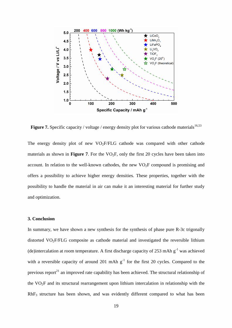
Figure 7. Specific capacity / voltage / energy density plot for various cathode materials16,53
The energy density plot of new VO2F/FLG cathode was compared with other cathode
materials as shown in Figure 7. For the VO2F, only the first 20 cycles have been taken into
account. In relation to the well-known cathodes, the new VO2F compound is promising and
offers a possibility to achieve higher energy densities. These properties, together with the
possibility to handle the material in air can make it an interesting material for further study
and optimization.
3. Conclusion
In summary, we have shown a new synthesis for the synthesis of phase pure R-3c trigonally
distorted VO2F/FLG composite as cathode material and investigated the reversible lithium
(de)intercalation at room temperature. A first discharge capacity of 253 mAh g-1
was achieved
with a reversible capacity of around 201 mAh g-1
for the first 20 cycles. Compared to the
previous report21
an improved rate capability has been achieved. The structural relationship of
the VO2F and its structural rearrangement upon lithium intercalation in relationship with the
RhF3 structure has been shown, and was evidently different compared to what has been
20
observed by Pérez-Flores et al.21
in their previous report. Upon electrochemical lithiation, the
anion lattice is transforming irreversibly from a 3/4 cubic close packed to a hexagonal closed
packed anion array. The structural rearrangement of VO2F upon lithiation appears to be
beneficial, lowering the polarization and due to an upshift of the output voltage.VO2F
competes well with the other cathode materials in terms of energy density. However, the
cycling stability needs to be improved. Further studies are necessary to understand the change
in the electrochemical profile and the capacity decay during the cycling.
Supporting Information
Refined crystal structure data, EDS, SEM and Vanadium (Kα) mapping of Li anode, EIS
spectra spectra for various states, XPS, Electrochemical performance of VO2F coated with
carbon black
Acknowledgements
Financial support by EU-RTD “Hi-C” (Novel in situ and in operando techniques for
characterization of interfaces in electrochemical storage systems") in the 7th FP, grant
agreement no. 608575 is gratefully acknowledged. The authors acknowledge the support by
the Karlsruhe Nano Micro Facility (KNMF) for electron microscopy and spectroscopy. C.V
acknowledges Dr. Christian Kübel and Prof. Dr. Horst Hahn for their continuous support.
Received: ((will be filled in by the editorial staff))
Revised: ((will be filled in by the editorial staff))
Published online: ((will be filled in by the editorial staff))
21
References
(1) Tarascon, J. M.; Armand, M. Nature 2001, 414 (6861), 359–367.
(2) Armand, M.; Tarascon, J.-M. Nature 2008, 451 (7179), 652–657.
(3) Amatucci, G.; Tarascon, J.-M. J. Electrochem. Soc. 2003, 150 (5), L9.
(4) Jain, A.; Hautier, G.; Moore, C. J.; Ping Ong, S.; Fischer, C. C.; Mueller, T.; Persson,
K. a.; Ceder, G. Comput. Mater. Sci. 2011, 50 (8), 2295–2310.
(5) Melot, B. C.; Scanlon, D. O.; Reynaud, M.; Rousse, G.; Chotard, J.-N.; Henry, M.;
Tarascon, J.-M. ACS Appl. Mater. Interfaces 2014, 6 (14), 10832–10839.
(6) Patoux, S.; Rousse, G.; Leriche, J. B.; Masquelier, C. Solid State Sci. 2004, 6 (10),
1113–1120.
(7) Nanjundaswamy, K. Solid State Ionics 1996, 92 (1-2), 1–10.
(8) Padhi, A. K.; Archibald, W. B.; Nanjundaswamy, K. S.; Godenough, J. B. J. Solid
State Chem. 1997, 128 (2), 267–272.
(9) Cabana, J.; Monconduit, L.; Larcher, D.; Palacín, M. R. Adv. Mater. 2010, 22 (35),
170–192.
(10) Rousse, G.; Tarascon, J. M. Chem. Mater. 2014, 26 (1), 394–406.
(11) Chen, R.; Ren, S.; Yavuz, M.; Guda, A. a.; Shapovalov, V.; Witter, R.; Fichtner, M.;
Hahn, H. Phys. Chem. Chem. Phys. 2015, 17 (26), 17288–17295.
(12) Ko, J. K.; Wiaderek, K. M.; Pereira, N.; Kinnibrugh, T. L.; Kim, J. R.; Chupas, P. J.;
Chapman, K. W.; Amatucci, G. G. ACS Appl. Mater. Interfaces 2014, 6 (14), 10858–
10869.
(13) Dambournet, D.; Chapman, K. W.; Chupas, P. J.; Gerald, R. E.; Penin, N.; Labrugere,
C.; Demourgues, A.; Tressaud, A.; Amine, K. J. Am. Chem. Soc. 2011, 133 (34),
13240–13243.
(14) Chen, R.; Ren, S.; Knapp, M.; Wang, D.; Witter, R.; Fichtner, M.; Hahn, H. Adv.
Energy Mater. 2015, 5 (9), DOI: 10.1002/aenm.201401814.
(15) Ren, S.; Chen, R.; Maawad, E.; Dolotko, O.; Guda, A. a.; Shapovalov, V.; Wang, D.;
Hahn, H.; Fichtner, M. Adv. Sci. 2015, DOI: 10.1002/advs.201500128.
(16) Louvain, N.; Karkar, Z.; El-Ghozzi, M.; Pierre, B.; Guérin, K.; Willmann, P. J. Mater.
Chem. A 2014, 2 (37).
(17) Reddy, M. V.; Madhavi, S.; Subba Rao, G. V.; Chowdari, B. V. R. J. Power Sources
2006, 162 (2 SPEC. ISS.), 1312–1321.
(18) Sleight, A. W. Inorg. Chem. 1969, 8 (8), 1764–1767.
(19) Cava, R. J.; Santoro, A.; Murphy, D. W.; Zahurak, S.; Roth, R. S. J. Solid State Chem.
1982, 42 (3), 251–262.
(20) Cava, R.; Santoro, a; Murphy, D.; Zahurak, S.; Roth, R. Solid State Ionics 1981, 5,
323–326.
(21) Pérez-Flores, J. C.; Villamor, R.; Ávila-Brande, D.; Gallardo Amores, J. M.; Morán,
E.; Kuhn, A.; García-Alvarado, F. J. Mater. Chem. A 2015, 3 (41), 20508–20515.

22
(22) Raccichini, R.; Varzi, A.; Passerini, S.; Scrosati, B. Nat. Mater. 2015, 14 (3), 271–279.
(23) Vinayan, B. P.; Nagar, R.; Rajalakshmi, N.; Ramaprabhu, S. Adv. Funct. Mater. 2012,
22 (16), 3519–3526.
(24) Vinayan, B. P.; Ramaprabhu, S. J. Mater. Chem. A 2013, 1 (12), 3865.
(25) William S. Hummers, J.; Offeman, R. E. J. Am. Chem. Soc 1958, 80, 1339.
(26) Carlson, S.; Larsson, A.-K.; Rohrer, F. E. Acta Crystallogr. Sect. B Struct. Sci. 2000,
56 (2), 189–196.
(27) Shannon, R. D. Acta Crystallogr. Sect. A 1976, 32 (5), 751–767.
(28) Clemens, O.; Slater, P. R. Rev. Inorg. Chem. 2013, 33 (2-3), 105–117.
(29) Berry, F. J.; Coomer, F. C.; Hancock, C.; Helgason, Ö.; Moore, E. A.; Slater, P. R.;
Wright, A. J.; Thomas, M. F. J. Solid State Chem. 2011, 184 (6), 1361–1366.
(30) Clemens, O.; Berry, F. J.; Wright, A. J.; Knight, K. S.; Perez-Mato, J. M.; Igartua, J.
M.; Slater, P. R. J. Solid State Chem. 2015, 226, 326–331.
(31) Berry, F. J.; Heap, R.; Helgason, Ö.; Moore, E. a.; Shim, S.; Slater, P. R.; Thomas, M.
F. J. Phys. Condens. Matter 2008, 20 (21), 215207.
(32) Berry, F. J.; Ren, X.; Heap, R.; Slater, P.; Thomas, M. F. Solid State Commun. 2005,
134 (9), 621–624.
(33) Clemens, O.; Berry, F. J.; Wright, A. J.; Knight, K. S.; Perez-Mato, J. M.; Igartua, J.
M.; Slater, P. R. J. Solid State Chem. 2013, 206, 158–169.
(34) Heap, R.; Slater, P. R.; Berry, F. J.; Helgason, O.; Wright, A. J. Solid State Commun.
2007, 141 (8), 467–470.
(35) Clemens, O.; Kuhn, M.; Haberkorn, R. J. Solid State Chem. 2011, 184 (11), 2870–2876.
(36) Berry, F. J.; Bowfield, A. F.; Coomer, F. C.; Jackson, S. D.; Moore, E. a; Slater, P. R.;
Thomas, M. F.; Wright, A. J.; Ren, X. J. Phys. Condens. Matter 2009, 21 (25), 256001.
(37) Clemens, O.; Berry, F. J.; Bauer, J.; Wright, A. J.; Knight, K. S.; Slater, P. R. J. Solid
State Chem. 2013, 203, 218–226.
(38) Clemens, O.; Wright, A. J.; Berry, F. J.; Smith, R. I.; Slater, P. R. J. Solid State Chem.
2013, 198, 262–269.
(39) Sturza, M.; Kabbour, H.; Daviero-Minaud, S.; Filimonov, D.; Pokholok, K.; Tiercelin,
N.; Porcher, F.; Aldon, L.; Mentré, O. J. Am. Chem. Soc. 2011, 133 (28), 10901–10909.
(40) Da Silva, K. L.; Menzel, D.; Feldhoff, A.; Kübel, C.; Bruns, M.; Paesano, A.; Düvel,
A.; Wilkening, M.; Ghafari, M.; Hahn, H.; Litterst, F. J.; Heitjans, P.; Becker, K. D.;
Šepelák, V. J. Phys. Chem. C 2011, 115 (15), 7209–7217.
(41) Heitjans, P.; Wilkening, M. MRS Bulletin. 2009, 915–922.
(42) Chernova, N. A.; Roppolo, M.; Dillon, A. C.; Whittingham, M. S. J. Mater. Chem.
2009, 19 (17), 2526–2552.
(43) Hung, F. Y.; Lui, T. S.; Liao, H. C. Appl. Surf. Sci. 2007, 253 (18), 7443–7448.
(44) Okada, M.; Lee, Y.; Yoshio, M. J. Power Sources 2000, 196–200.
(45) Shao-Horn, Y.; Middaugh, R. L. Solid State Ionics 2001, 139 (1-2), 13–25.
23
(46) Aarik, J.; Aidla, A.; Uustare, T.; Ritala, M.; Leskelä, M. Appl. Surf. Sci. 2000, 161 (3),
385–395.
(47) Thackeray, M. M.; Johnson, C. S.; Kim, J. S.; Lauzze, K. C.; Vaughey, J. T.; Dietz, N.;
Abraham, D.; Hackney, S. a.; Zeltner, W.; Anderson, M. a. Electrochem. commun.
2003, 5 (9), 752–758.
(48) Cheng, H.-M.; Wang, F.-M.; Chu, J. P.; Santhanam, R.; Rick, J.; Lo, S.-C. J. Phys.
Chem. C, 2012, 116, 7629–7637.
(49) Müller, U. Anorganische Strukturchemie; Teubner Studienbücher Chemie;
Vieweg+Teubner Verlag: Wiesbaden, 2004.
(50) Cui, C.; Wu, G.; Shen, J.; Zhou, B.; Zhang, Z.; Yang, H.; She, S. Electrochim. Acta
2010, 55 (7), 2536–2541.
(51) Chen, Z.; Cao, L.; Chen, L.; Zhou, H.; Xie, K.; Kuang, Y. J. Mater. Chem. A 2015, 3
(16), 8750–8755.
(52) Bohnke, C.; Fourquet, J. L.; Randrianantoandro, N.; Brousse, T.; Crosnier, O. J. Solid
State Electrochem. 2001, 5 (1), 1–7.
(53) Pralong, V.; Gopal, V.; Caignaert, V.; Duffort, V.; Raveau, B. Chem. Mater. 2012, 24
(1), 12–14.
For table of contents only
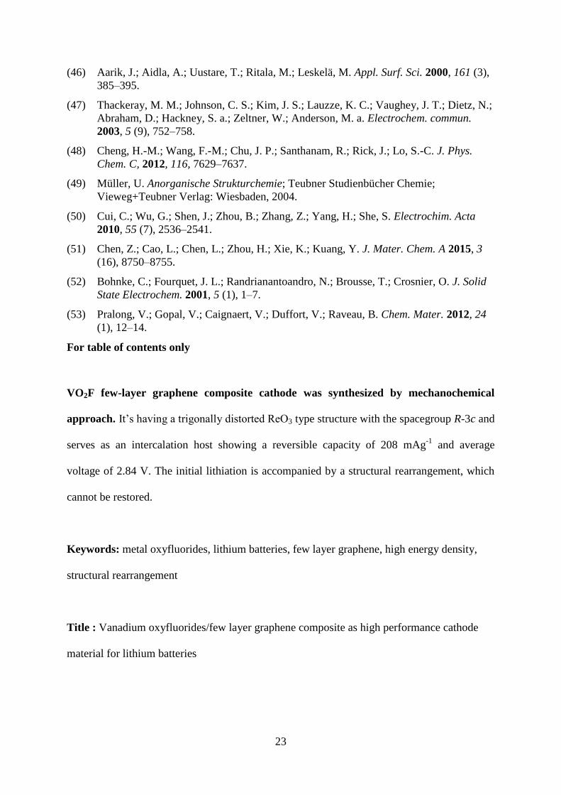
VO2F few-layer graphene composite cathode was synthesized by mechanochemical
approach. It’s having a trigonally distorted ReO3 type structure with the spacegroup R-3c and
serves as an intercalation host showing a reversible capacity of 208 mAg-1
and average
voltage of 2.84 V. The initial lithiation is accompanied by a structural rearrangement, which
cannot be restored.
Keywords: metal oxyfluorides, lithium batteries, few layer graphene, high energy density,
structural rearrangement
Title : Vanadium oxyfluorides/few layer graphene composite as high performance cathode
material for lithium batteries
24
ToC figure


![w%iC =.s^ c1 ayY sR ]&N · 2020-05-11 · y'J sR .;^ t%1 e$A gr*# {F Z1 -[1 \pS ]&, {^ w%iC =.s^ /=cN Z^B ;=r1 ayS -[1 '%/%A u-h!B ;=r1 ayS n\a*^ -r$ wG y%R {# wG a;@A w[IB ;=r1 ayS](https://img.pdfslide.net/doc/110x75/5f86c9ae5a1bdb60ed1eb04d/wic-s-c1-ayy-sr-n-2020-05-11-yj-sr-t1-ea-gr-f-z1-1-ps-.jpg)