Embed Size (px)
Citation preview
Artisan Scientific - Quality Instrumentation ... Guaranteed | (888) 88-SOURCE | www.artisan-scientific.com
Introduction
We would like to express our gratitude for your purchase of our autoclave. This brochure covers the operation method and a simple maintenance method for the Autoclave HV-25/50/85/110 you now own. We hope that owing to your proper handling the autoclave can demonstrate its full performance and that you will make regular use of it for a long time.
For optional equipment (0 printer, O floating sensor, 0 cooling fan, automatic water supply equipment), if any, read the attached operation manuals for the equipment.
Please check whether or not the product conforms to your order and confirm that it was not damaged during transportation, Should it be damaged or out of order, please contact the sales outlet from which you purchased it.
Be sure to send the enclosed warranty registration card to us.
+\\\\\\\\\\\\\\\\\\\\\\\\\\\\\\\\\\\\\\\\\\\\\\\\\\\\\\\\\\\\\\\\\\\\\\\\\\\\\\\\\\\\\\\\\\\\\\\\\\\\\\\\\\\\\\\\\\\\\\K
2 Q (1) No part of this document may be reproduced without permission. + Q (2) The contents of this document are subject to change without notice. Q 2 (3) This document has been carefully compiled. If you have any questions or necessary t $ information uncovered in the document, please contact us or the sales outlet from which ? $ you purchased the product. k\\\\\\\\\\\\\\\\\\\\\\\\\\\\\\\\\\\\\\\\\\\\\\\\\\\\\\\\\\\\\\\\\\\\\\\\\\\\\\\\\\\\\\\\\\\\\\\\\\\\\\\\\\\\\\\\\\\\\\~:
Table of Contents
Date Description of Revision
Jun . 1 1, 1996 Additions and revisions to WARNING, CAUTION and NOTE.
Instructions under "Replacing Lid Packing" in Chapter 4: Maintenance and Service revised. Instructions for "Operation with a WaSte Disposal Bag" added.
Instructions for "Successive Operations with the Product" added.
Artisan Scientific - Quality Instrumentation ... Guaranteed | (888) 88-SOURCE | www.artisan-scientific.com
Before Using
In this manual the following headwords are applied to items to which great attention should be given:
WARNING: Precaution indicating an imminent dangerous situation which if not avoided may lead to death or serious injury.
a CAUTION: Precaution indicating a dangerous situation which if not avoided may lead to moderate or slight injury.
IMPORTANT: Indicates items you are strongly advised to obey.
NOTE: Items you should pay attention to during operation.
r /(\ WARNING
Never use the autoclave to sterilize the following dangerous objects or substances containing alkali content. Sterilization of such objects may cause explosion, corrosion of the working chamber or piping, and deterioration in packing.
/ List of Dangerous Objects:
(1) Explosive substances Nitroglycol, nitroglycerin, nitrocellulose, and other explosive nitric esters.
*Trinitrobenzene, trinitrotoluene, picric acid, and other explosive nitro compounds. *Peracetic acid, methyl ethyl ketone peroxide, benzoyl peroxide, and other organic peroxides.
(2) Ignitable substances *Metallic lithium, potassium, sodium, yellow phosphorous, phosphorus sulfide, and red phosphorus Celluloids, calcium carbide (carbide), lime phosphide, and magnesium powder
Aluminum powder, magnesium powder, and metallic powders other than aluminum powder *Sodium.dithionite (or sodium hydrosulfite)
(3) Oxidizer *Potassium chlorate, sodium chlorate, ammonium chlorate, and other chlorates Potassium perchlorate, sodium perchlorate, ammonium perchlorate, and other perchlorates. *Potassium peroxide, sodium peroxide, barium peroxide, and other inorganic peroxides *Potassium nitrate, sodium nitrate, ammonium nitrate, and other nitrates Sodium chlorite and other chlorites Calcium hypochlorite and other hypochlorites
(4) Inflammable substances E t h y l ether, gasoline, acetaldehyde, propylene oxide, carbon disulfide, and other substances whose flash points range from -30°C to 0°C exclusive.
*Methanol, ethanol, xylene, benzyl acetate (or amyl acetate), and other substances whose flash points range from 0°C to 30°C exclusive. Kerosene, gas oil, turpenine oil, isopentyl alcohol (or isoamyl alcohol), acetic acid, and other substances whose flash points range from 30°C to 65°C exclusive.
Artisan Scientific - Quality Instrumentation ... Guaranteed | (888) 88-SOURCE | www.artisan-scientific.com
(5) Harnmable gas (hydrogen, acetylene, ethylene, methane, ethane, propane, butane, and other
substances that are gas at a temperature of 15°C at 1 atmospheric pressure.)
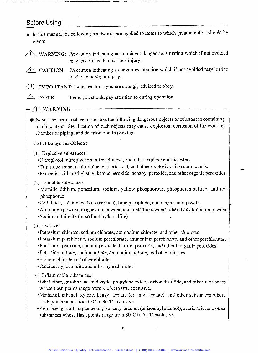
Before opening the lid, be sure to check that the pressure gauge reads "0 kgf/cm2".
I 0 Never modify the product.
- A CAUTION
Foreign matter (metals, liquid) may enter through the vent hole. Operating the equipment with such foreign matter inside may cause trouble with the equipment, fire and electric shock.
Do not forcibly bend, twist, tie or extend the power cord. Do not place heavy objects on the cord. A damaged cord or exposed wire may cause fire or electric shock.
Never connect the power cord to a power supply other than the voltage that is rated. Connection to such a power supply may cause fire or electric shock.
If not plugging the sterilizer into a grounded socket, ground the equipment separately before connecting it to a power source.
Never ground to a gas pipe or vinyl chloride water service pipe.
Before closing the lid, check to see that there are no foreign matters in the portion of the lid which is in contact with the lid packing. Foreign matters may cause steam leakage.
Whenever a bag, such as a waste disposal bag, is used for sterilization, put it in the wire mesh basket and place the basket in the working chamber. If the bag is placed directly in the working chamber, the piping may become clogged by it and overheating, overpressurization, and/or lack of water may result. ,
Be careful not to pinch hands when closing the Iid.
Do not put your face or hands close to the working chamber when lifting the lid after operations are complete; steam will gush out of the opening of the chamber.
The lid, working chamber, packing and panel are extremely hot immediately after the completion of operation. Do not touch the equipment or you may get burned.
Put on heat insulation gloves before removing a substance from the working chamber. Do not put your hands into the chamber until the steam has been vented.
@ It takes a lot of time for the liquid to cool. Be sure to check that the temperature has dropped sufficiently before unloading the liquid from the working chamber, or you may get burned.
Artisan Scientific - Quality Instrumentation ... Guaranteed | (888) 88-SOURCE | www.artisan-scientific.com
Do not unload the exhaust bottle or drain the working chamber when the chamber is under
pressure. Boiling water or steam may gush out, and you may get burned.
a Do not unload the exhaust bottle before water in the bottle has been sufficiently cooled.
0 Do not dispose of used batteries in fire; they may explode.
a If you encounter any anomaly (e.g. abnormal sound and smell, smoking), immediately shut off power. After checking to see that the abnormal condition is not continuing, call us or our authorized sales outlet from shich you purchased it.
0 If the display differs between the steps, turn off the POWER switch, and then turn the power on again. If the condition still remains, turn off the power and call us or our authorized sales outlet from which you purchased it.
a If the equipment is installed in a place which is 800 m or higher than sea level (i.e. under low pressure in mountain areas), the over pressure preventive device and the air vent device require changes to their setting. In this case, be sure to contact us. Do not use the equipment before changing the setting.
a In transporting the equipment, put the lid on and slide the open/close lever to the end of the close side to prevent the lid from opening.
When moving the lid, do not hold it by the handle, otherwise the lid may become difficult to close.
Artisan Scientific - Quality Instrumentation ... Guaranteed | (888) 88-SOURCE | www.artisan-scientific.com
How to Read This Manual
a This operation manual consists of the following sections covering the information required for proper operation of the autoclave HV-25/50/85/110:
Chapter 1. What Is Autoclave HV-25/50185/11 O?"
This section describes the uses and features of the product and the names and functions of its parts.
Chapter 2. Installation
This section explains where the equipment should be installed and how to install it. The product incorporates precision parts. Be sure to follow the instructions covered in this document.
Chapter 3. Operation Method
This section illustrates how to change various set values, and describes operation before starting the equipment and after automatic operation. This section also covers the display and action of the equipment during automatic operation.
Chapter 4. Maintenance and Servicing
This section explains the methods for draining water from the exhaust bottle or working charn- ber, servicing the body, and parts replacement.
Chapter 5. Specifications
his section includes dimensions, power consumption, working range, piping and wiring dia- grams of the product. Refer to this section as is required.
Chapter 6. In the Event of Suspected Failure
This section covers troubleshooting procedures for the product. If you encounter anything sus- pected to be due to failure, read this section first of all.
Artisan Scientific - Quality Instrumentation ... Guaranteed | (888) 88-SOURCE | www.artisan-scientific.com
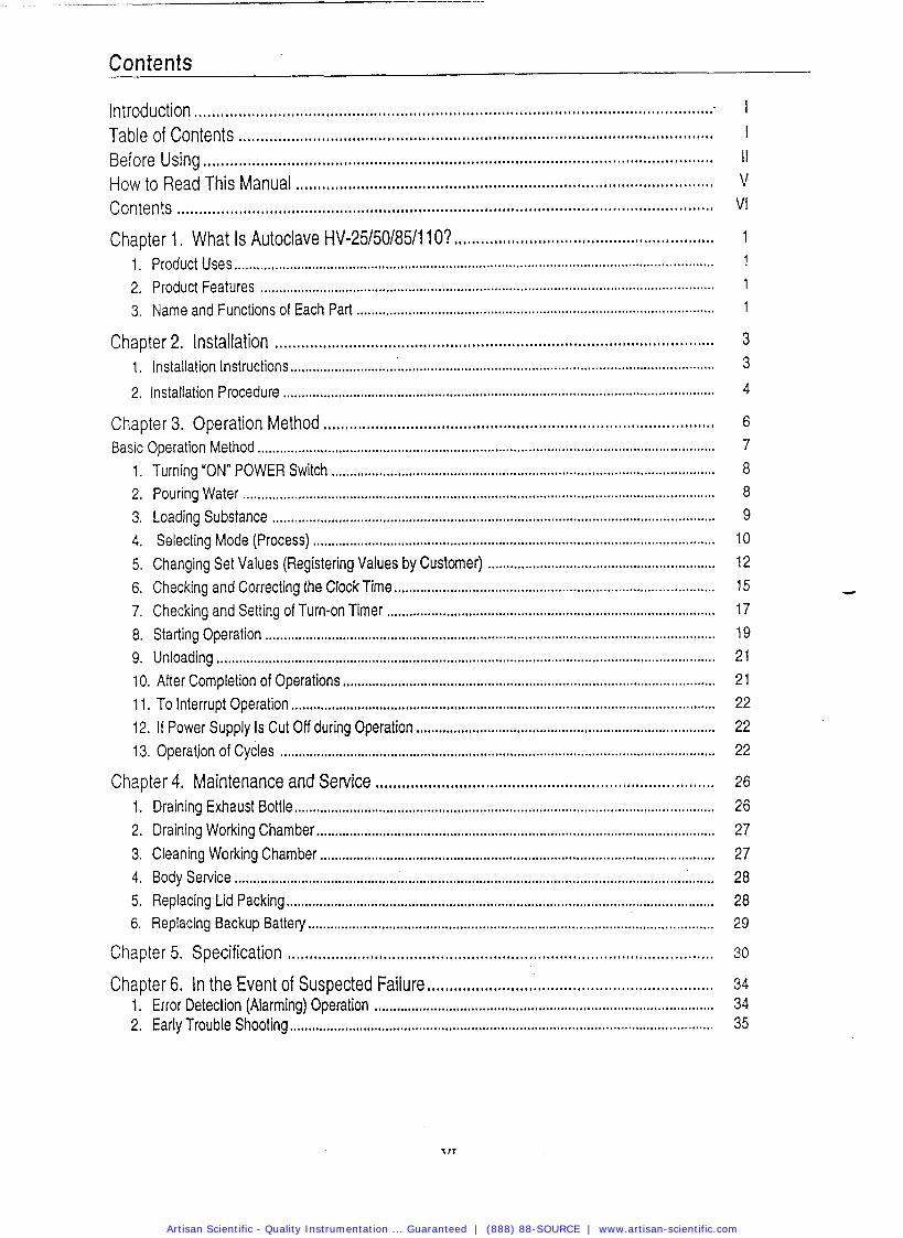
Contents
Introduction ................... .. ............................................................................................ Table of Contents ......................................................... .................................... Before Using ............................................................................................................... How to Read This Manual ................... .... ................................................................. Contents .................... ... ..............................................................................................
........................................................... Chapter 1 . What Is Autoclave HV-25/50/8511 l o ? ................................................................................................................................. 1 . Product Uses
2 . Product Features .......................................................................................................................... 3 . Name and Functions of Each Part .............................................................................................
Chapter 2 . Installation ................... ... ....................................................................... 1 . Installation Instructions ........................... .................................................................................... 2 . Installation Procedure ................................................................................................................
Chapter 3 . Operation Method ................... ...... ......................................................... Basic Operation Method ...........................................................................................................................
Turning "ON" POWER Switch .................................................................................................... Pouring Water ............................................................................................................................... Loading Substance ....................................................................................................................... Selecting Mode (Process) ............................................................................................................
Changing Set Values (Registering Values by Customer) ............................................................. Checking and Correcting the Clock Time ................................... .... ............................................... Checking and Setting of Turn-on Timer ...................................................................................... Starting Operation ........................................................................................................................ Unloading ......................................................................................................................................
10 . After Completion of Operations .................................................................................................. 11 . To Interrupt Operation ................................................................................................................ 12 . If Power Supply Is Cut Off during Operation ................... .. ....................................................... 13 . Operatjon of Cycles ................... .. .......................................................................................
Chapter 4 . Maintenance and Service ............................................................................. 1 . Draining Exhaust Bottle ................... A .................................................................................... 2 . Draining Working Chamber ........................... ............ .................................................................... 3 . Cleaning Working Chamber ....................................................................................................... 4 . Body Service ................................................................................................................................ 5 . Replacing Lid Packing ................................................................................................................... 6 . Replacing Backup Battery ........................................................................................................
Chapter 5 . Specification ................... .. ..................................................................... Chapter 6 . In the Event of Suspected Failure .................................................................
1 . Error Detection (Alarming) Operation ................... .. ...... .. ...................................................... 2 . Early Trouble Shooting .................................... .... ..........................................................................
Artisan Scientific - Quality Instrumentation ... Guaranteed | (888) 88-SOURCE | www.artisan-scientific.com
Cha~te r 1. What Is Autoclave HV-25/50/85111 O?
1. Product Uses
This product is designed for research use only (Modes 1 - 3). It is not labeled or marketed for use in medical or clinical applications. This product is also used to liquefy media (Mode 4). Mode 4 can also be used to prewarm the chamber for a faster start.
2. Product Features
This product is equipped with a cover for the lid that may be heated at hlgh temperature during use. The product incorporates an automatic timer which permits you to begin operation at any desired time within a period of one week. The product is provided with a variety of modes of operation. The modes are divided into two broad categories: Sterilization-warming mode and liquefaction mode. If you do not take out the sterilized medium immediately, then select the sterilization-warming mode, and coagulation is prevented. To liquefy a coagulated medium, use the liquefaction mode. This autoclave can be set to automatically exhaust % inside the chamber at a desired rate (exhaust valve aperture) after sterilization is over. Optional equipment (printer, floating sensor, cooling fan, automatic water supply equipment) can be installed onto the product at a later date.
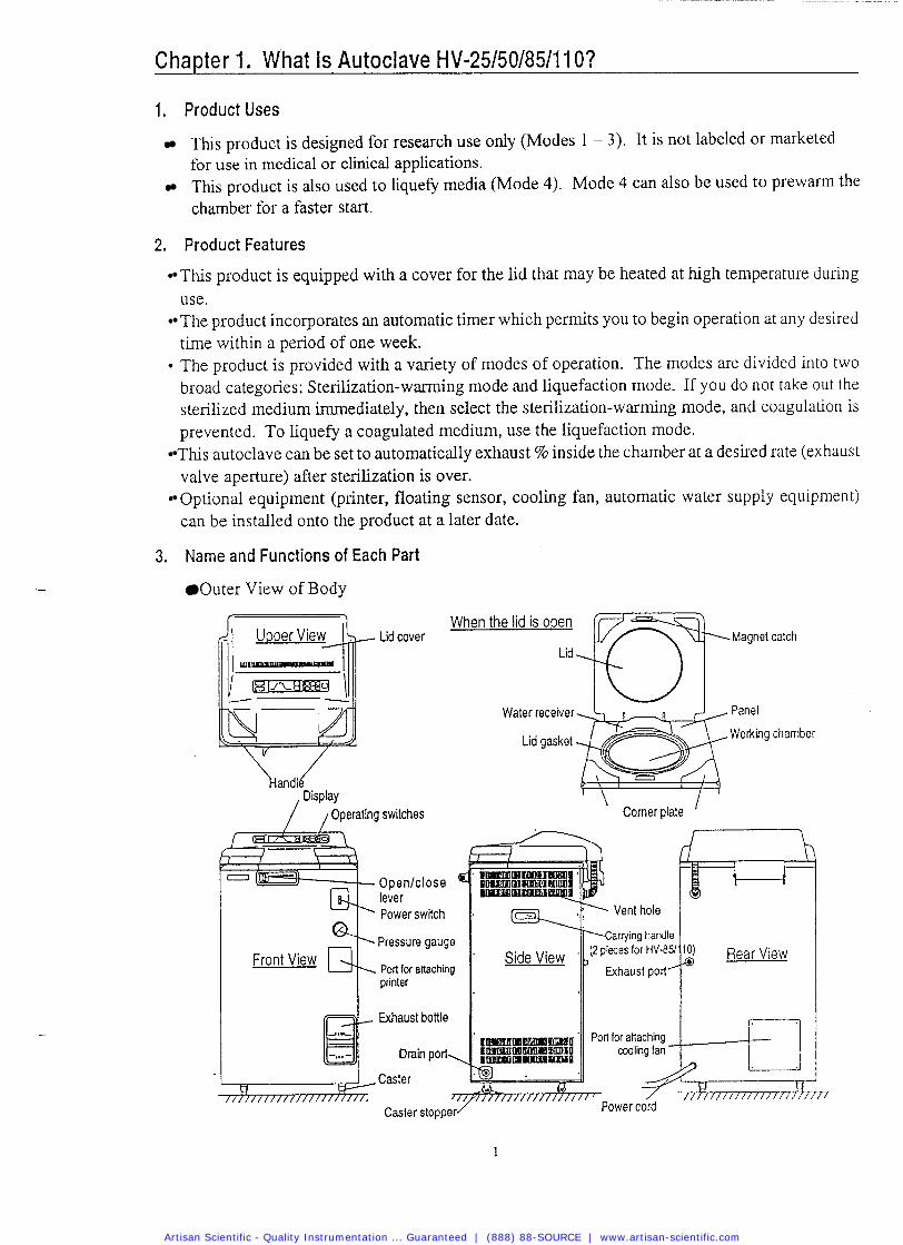
3. Name and Functions of Each Part
Outer View of Body
When the lid is open
Lid nT Magnet catch
!I:er switch
- % Pressure gauge Front View
Port for attaching printer
Exhaust bottle
-,..- El- Drain port,
Water receiver Panel
Lid gasket Working chamber
\ Comer plate I
Vent hole
arrying handle
Side View 11 (2 pieces for HV-85
Exhaust port' lo) Rear View fa
Artisan Scientific - Quality Instrumentation ... Guaranteed | (888) 88-SOURCE | www.artisan-scientific.com
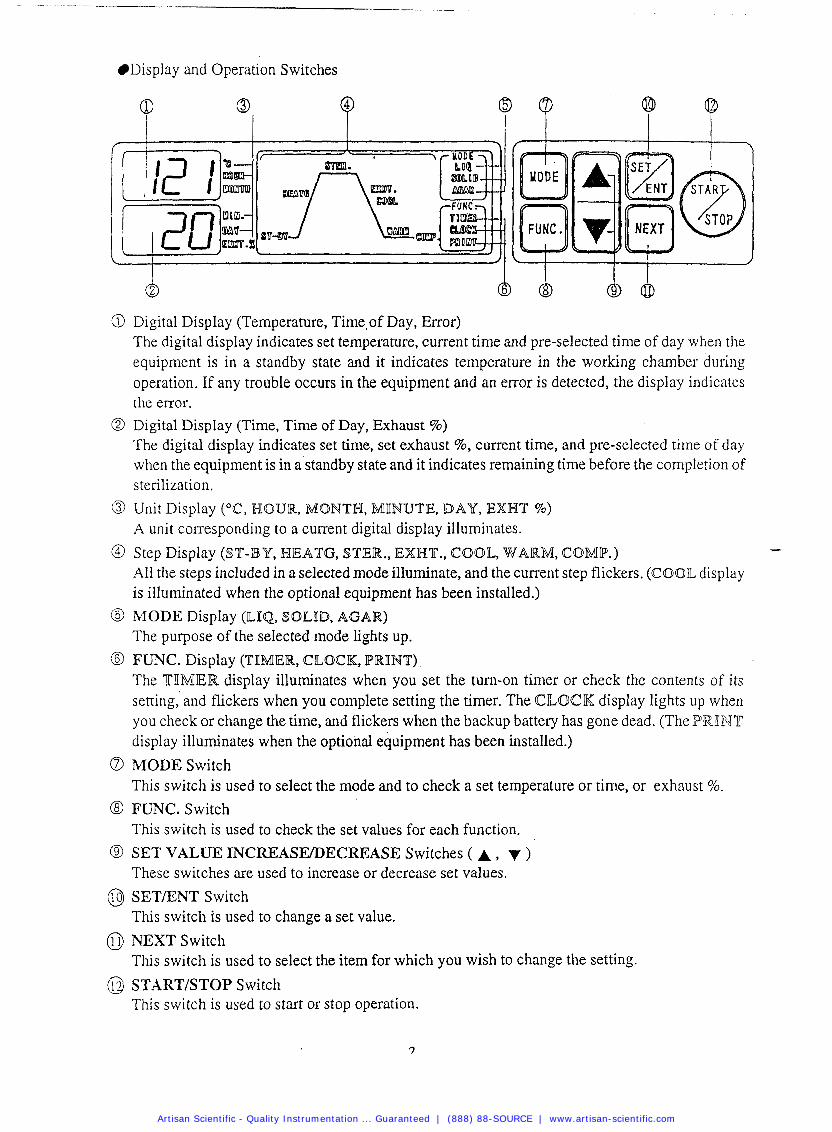
Display and Operation Switches
@ Digital Display (Temperature, Time,of Day, Error) The digital display indicates set temperature, current time and pre-selected time of day when the equipment is in a standby state and it indicates temperature in the working chamber during operation. If any troubIe occurs in the equipment and an error is detected, the display indicates the error.
@ Digital Display (Time, Time of Day, Exhaust %) The digital display indicates set time, set exhaust %, current time, and pre-selected time of day when the equipment is in a'standby state and it indicates remaining time before the completion of sterilization.
@ Unit Display ("C, HOUR, MONTH, MINUTE, DAY, EWHT %) A unit corresponding to a current digital display illuminates.
@ Step Display (ST-BY, HIEATG, $TIER., EXWT., COOL, WARM, COMP.) - All the steps included in a selected mode illuminate, and the current step flickers. (COOL display is illuminated when the optional equipment has been installed.)
6) MODE Display (ILIQ, SOILID, AGAR) The purpose of the selected mode Lights up.
@ FUNC. Display (TIMIER, CLOCK, PRINT) The TIIMIER display illuminates when you set the turn-on timer or check the contents of its setting, and flickers when you complete setting the timer. The CLOCK display lights up when you check or change the time, and flickers when the backup battery has gone dead. (The PRIINT display illuminates when the optional equipment has been instalIed.)
a MODE Switch This switch is used to select the mode and to check a set temperature or time, or exhaust 5%.
8 FUNC. Switch This switch is used to check the set values for each function.
@ SET VALUE INCREASEDECREASE Switches ( A , ) These switches are used to increase or decrease set values.
@ S E T E N T Switch This switch is used to change a set value.
0 NEXT Switch This switch is used to select the item for which you wish to change the setting.
@ START/STOP Switch This switch is used to start or stop operation.
Artisan Scientific - Quality Instrumentation ... Guaranteed | (888) 88-SOURCE | www.artisan-scientific.com
Chapter 2. Installation
- A CAUTION If the equipment is installed in a place which is 800 m or higher than sea level (i.e. under low pressure in mountain areas), its specifications require to be changed. In this case, be sure to contact us. Do not use the equipment before changing.
In transporting the equipment, put the lid on and slide the opedclose lever to the end of the close side to prevent the lid from opening.
When moving the lid, do not hold it by the handle, otherwise the lid may become difficult to close.
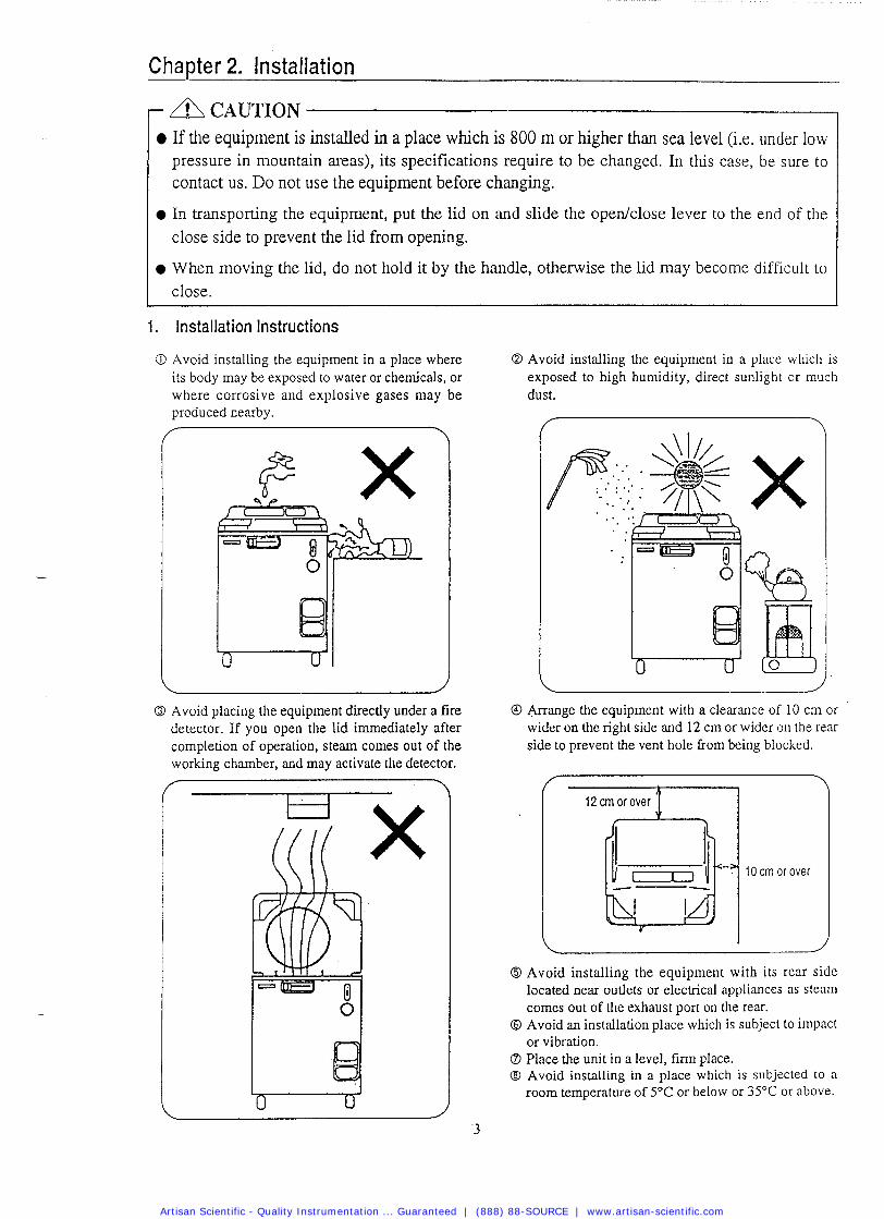
1. Installation Instructions
O Avoid installing the equipment in a place where its body may be exposed to water or chemicals, or where corrosive and explosive gases may be produced nearby.
Q Avoid installing the equipment in a place which is exposed to high humidity, direct sunlight or much dust.
O Avoid placing the equipment directly under a fire detector. If you open the lid immediately after completion of operation, steam comes out of the working chamber, and may activate the detector.
@ Arrange the equipment with a clearance of 10 cm or wider on the right side and 12 cm or wider on the rear side to prevent the vent hole fiom being blocked.
I 2 cm or over 1
10 cm or over
O Avoid installing the equipment with its rear side located near outlets or electrical appliances as steam comes out of the exhaust port on the rear.
@ Avoid an installation place which is subject to impact or vibration.
6 Place the unit in a level, fm place. @ Avoid installing in a place which is subjected to a
room temperature of 5°C or below or 35OC or above.
Artisan Scientific - Quality Instrumentation ... Guaranteed | (888) 88-SOURCE | www.artisan-scientific.com
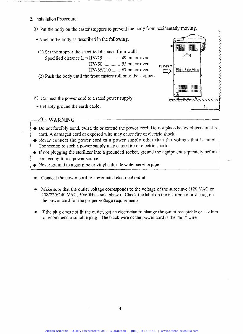
2, Installation Procedure
@ Put the body on the caster stoppers to prevent the body from ac
Anchor the body as described in the following.
(1) Set the stopper the specified distance from walls. Specified distance L = HV-25 .............. 49 cm or over
HV-50 .............. 55 cm or over Push ,, HV-85/110 ....... 67 cm or over
(2) Push the body until the front casters roll onto the stopper.
@ Connect the power cord to a rated power supply.
Reliably ground the earth cable. w a WARNING
Do not forcibly bend, twist, tie or extend the power cord. Do not place heavy objects on the cord. A damaged cord or exposed wire may cause fire or electric shock. Never connect the power cord to a power supply other than the voltage that is rated. Connection to such a power supply may cause f ~ e or electric shock.
0 If not plugging the sterilizer into a grounded socket, ground the equipment separately before connecting it to a power source.
0 Never ground to a gas pipe or vinyl chloride water service pipe.
Connect the power cord to a grounded electrical outlet.
Make sure that the outlet voltage corresponds to the voltage of the autoclave (120 VAC or 20812201240 VAC, 50160Hz single phase). Check the label on the instrument or the tag on the power cord for the proper voltage requirements.
If the plug does not fit the outlet, get an electrician to change the outlet receptable or ask him to recommend a suitable plug. The black wire of the power cord is the "hot" wire.
Artisan Scientific - Quality Instrumentation ... Guaranteed | (888) 88-SOURCE | www.artisan-scientific.com
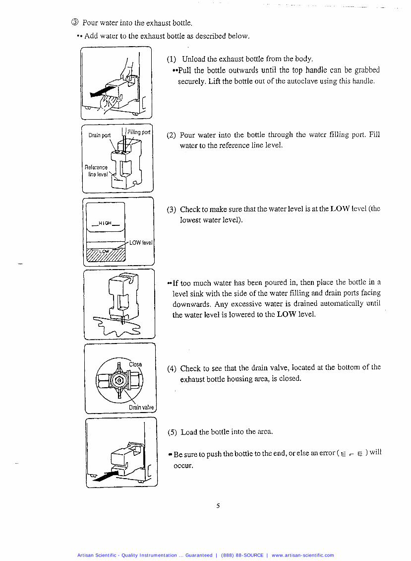
@ Pour water into the exhaust bottle.
Add water to the exhaust bottle as described below.
Drain po Pol
Reference line level
(1) UnIoad the exhaust bottle from the body. Pull the bottle outwards until the top handle can be grabbed securely. Lift the bottle out of the autoclave using this handle.
(2) Pour water into the bottle through the water filling port. Fill water to the reference line level.
LOW level
1 Drain valve
(3) Check to make sure that the water level is at the LOW level (the lowest water level).
If too much water has been poured in, then place the bottle in a level sink with the side of the water filling and drain ports facing downwards. Any excessive water is drained automatically until the water level is lowered to the LOW level.
(4) Check to see that the drain valve, located at the bottom of the exhaust bottle housing area, is closed.
( 5 ) Load the bottle into the area.
Be sure to push the bottle to the end, or else an error ( E , E ) will occur.
Artisan Scientific - Quality Instrumentation ... Guaranteed | (888) 88-SOURCE | www.artisan-scientific.com
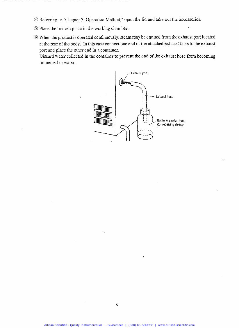
@ Referring to "chapter 3. Operation Method," open the lid and take out the accessories.
@ Place the bottom place in the working chamber.
@ When the product is operated continuously, steam may be emitted from the exhaust pon located at the rear of the body. In this case connect one end of the attached exhaust hose to the exhaust port and place the other end in a container. Discard water collected in the container to prevent the end of the exhaust hose from becoming immersed in water.
Bottle orsimilar item (for receiving steam)
Artisan Scientific - Quality Instrumentation ... Guaranteed | (888) 88-SOURCE | www.artisan-scientific.com
Chapter 3. Operation Method
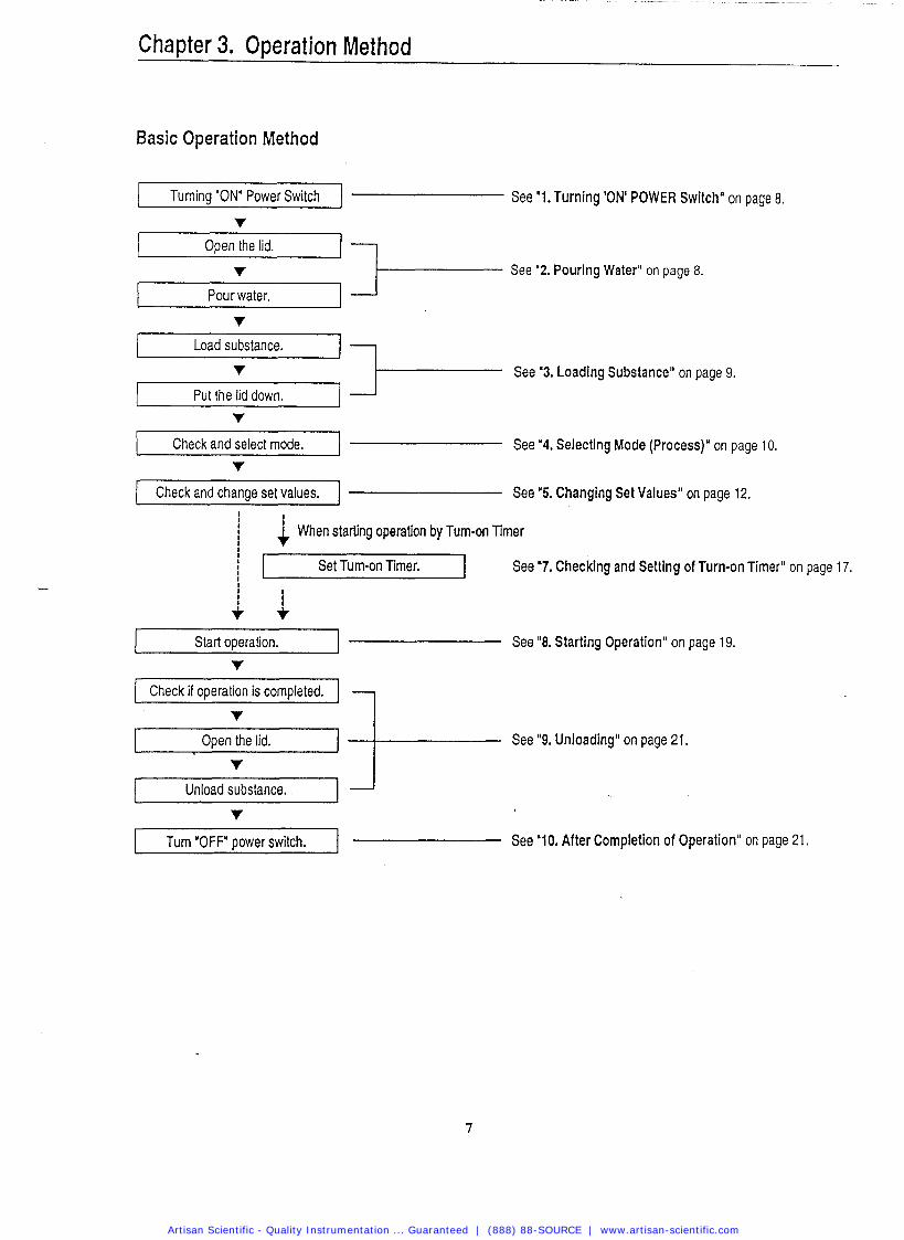
Basic Operation Method
Turning "ON' Power Switch 1 See '1. Turning 'ON' POWER Switch" on page 8.
v Open the lid. I1
v See '2. Pouring Water" on page 8.
Pour water.
v
i Load substance. 11 v A- See '3. Loading Substance" on page 9.
1 Put the lid down.
i Check and select mode. - See "4. Selecting Mode (Process)" on page 10.
I Check and change set values. 1 --------- See '5. Changing Set Values" on page 12. I I
i i When starting operation by Turn-on Timer
I Start operation. 1 See "8. Starting Operation" on page 19.
1 I Set Tum-on Timer.
Check if operation is completed. I v
1 Open the lid.
I
See "9. Unloading" on page 21.
v Unload substance.
v
See "7. Checking and Setting of Turn-on Timer" on page 17.
Turn 'OFF' power switch. I --------- See "10. After Completion of Operation'' on page 21.
Artisan Scientific - Quality Instrumentation ... Guaranteed | (888) 88-SOURCE | www.artisan-scientific.com
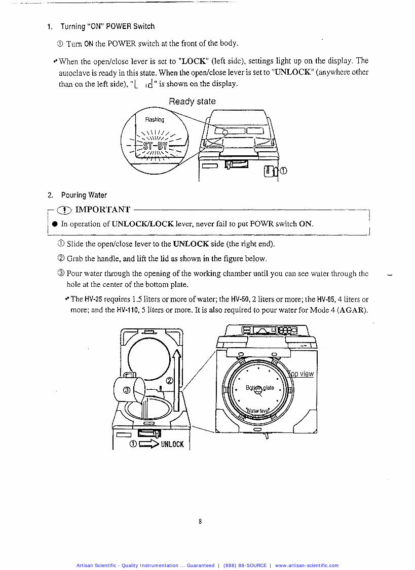
1. Turning "ON" POWER Switch
O Turn ON the POWER switch at the front of the body.
When the openiclose lever is set to "LOCK" (left side), settings light up on the display. The autoclave is ready in this state. When the open/close lever is set to "UNLOCK" (anywhere other than on the left side), " L is shown on the display.
Ready state
2. Pouring Water
, <r>. IMPORTANT
0 In operation of UNLOCKLOCK lever, never fail to put POWR switch ON.
a Slide the open/close lever to the UNLOCK side (the right end).
@ Grab the handle, and lift the lid as shown in the figure below.
@ Pour water through the opening of the working chamber until you can see water through the hole at the center of the bottom plate.
The HV-25 requires 1.5 liters or more of water; the HV-50,2 liters or more; the HV-85,4 liters or more; and the HV-110.5 liters or more. It is also required to pour water for Mode 4 (AGAR).
Artisan Scientific - Quality Instrumentation ... Guaranteed | (888) 88-SOURCE | www.artisan-scientific.com
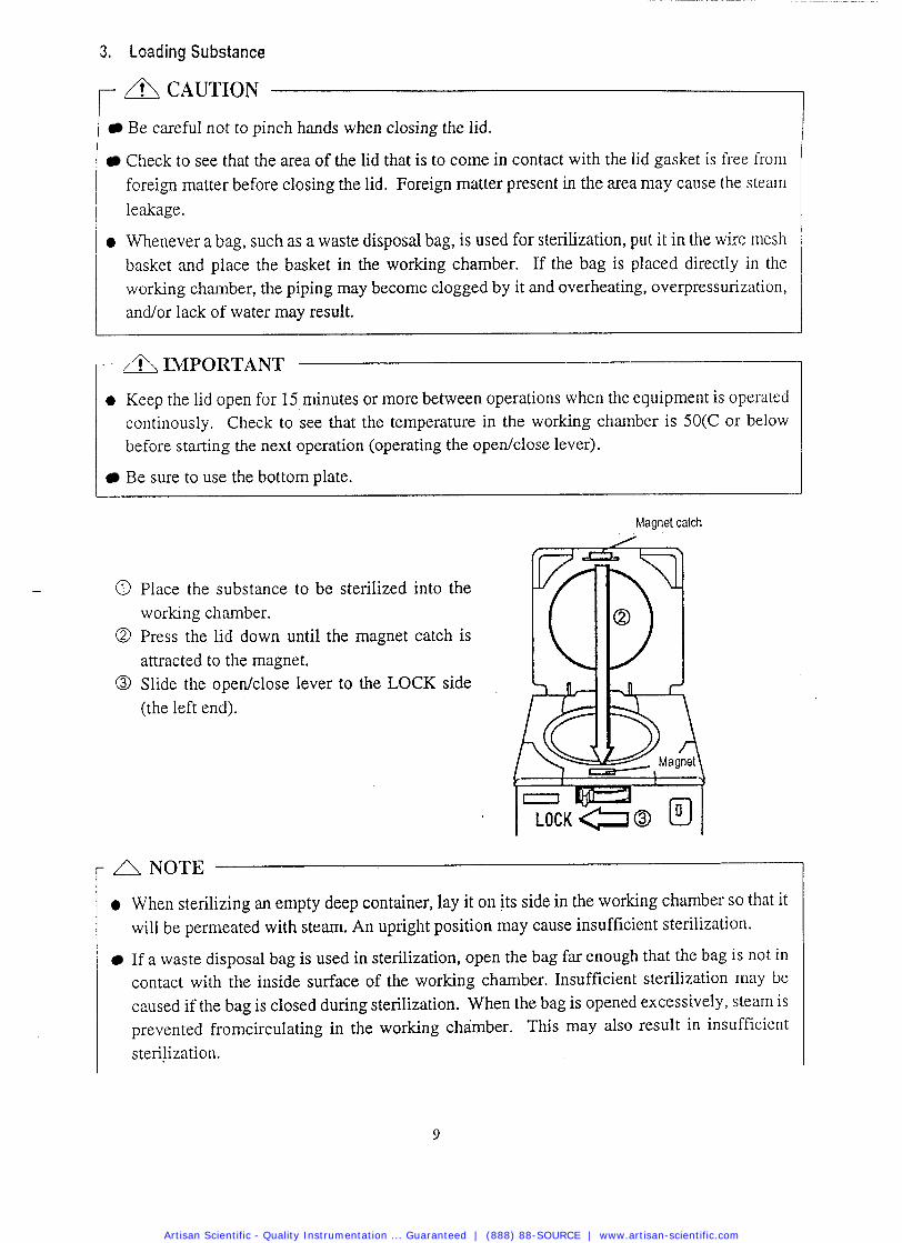
3. Loading Substance
I Be careful not to pinch hands when closing the lid.
Check to see that the area of the lid that is to come in contact with the lid gasket is free from foreign matter before closing the lid. Foreign matter present in the area may cause the steam leakage.
a Whenever a bag, such as a waste disposal bag, is used for sterilization, put it in the wire mesh basket and place the basket in the working chamber. If the bag is placed directly in the working chamber, the piping may become clogged by it and overheating, overpressurization, andor lack of water may result.
A IMPORTANT
0 Keep the lid open for 15 minutes or more between operations when the equipment is operated continously. Check to see that the temperature in the working chamber is 50(C or below before starting the next operation (operating the opedclose lever).
Be sure to use the bottom plate.
- @ Place the substance to be sterilized into the working chamber.
@ Press the lid down until the magnet catch is attracted to the magnet.
@ Slide the opedclose lever to the LOCK side (the left end).
Magnet catch
3 y A NOTE
a When sterilizing an empty deep container, lay it on its side in the working chamber so that it will be permeated with steam. An upright position may cause insufficient sterilization.
If a waste disposal bag is used in sterilization, open the bag far enough that the bag is not in contact with the inside surface of the working chamber. Insufficient sterilization may be caused if the bag is closed during sterilization. When the bag is opened excessively, steam is prevented fromcirculating in the working chamber. This may also result in insufficient sterilization.
Artisan Scientific - Quality Instrumentation ... Guaranteed | (888) 88-SOURCE | www.artisan-scientific.com
Do not pile specimens on top of one another. When the chamber is overly packed, steam fails
to penetrate to all points, resulting in incomplete sterilization.
0 In sterilizing liquids such as chemical and medium, pay attention to the quantity of the liquid in relation to its container. For an Erlenmeyer flask, the amount of chemical should be approx. 314 of the capacity of the container; for a test tube, the appropriate quantity of chemical is approx. half of the capacity of the container. Too much chemical may result in overflow from the container during the temperature rising or cooling process.
When using a container, loosen the cap or use a breathable cap. An unbreathable cap may cause the container to burst.
In the case of liquefaction of agar medium, its quantity should be 2 liters or less per container. Two liters or more of agar medium ,may not be completely liquefied.
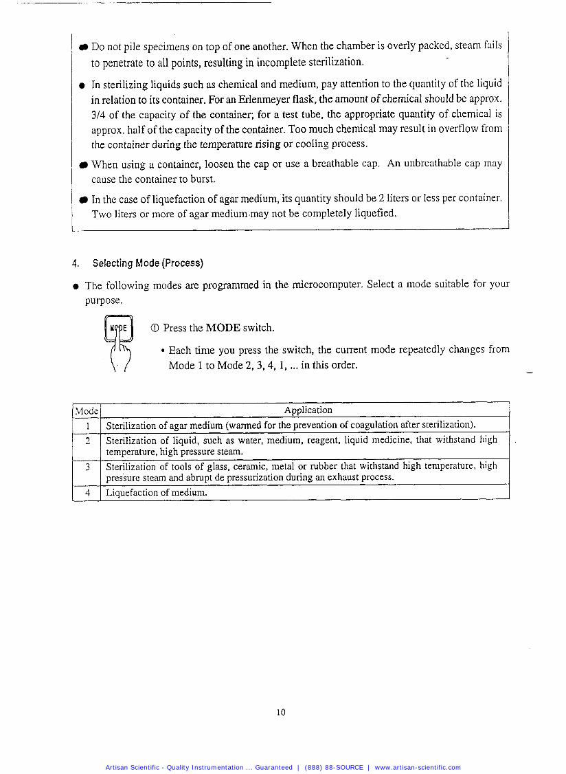
4. Selecting Mode (Process)
The following modes are programmed in the microcomputer. Select a mode suitable for your purpose.
O Press the MODE switch.
Each time you press the switch, the current mode repeatedly changes from
\. / Mode 1 to Mode 2, 3,4, 1, ... in this order.
Mode 1
2
Application Sterilization of agar medium (warmed for the prevention of coagulation after sterilization). Sterilization of liquid, such as water, medium, reagent, liquid medicine, that withstand high
3
temperature, high pressure steam. Sterilization of tools of glass, ceramic, metal or rubber that withstand high temperature, high
4
pressure steam and abrupt de pressurization during an exhaust process. Liquefaction of medium.
Artisan Scientific - Quality Instrumentation ... Guaranteed | (888) 88-SOURCE | www.artisan-scientific.com
Mode
1
Mode
2
Mode
3
Mode
4
Initial Set Value X I - J -
Step Display
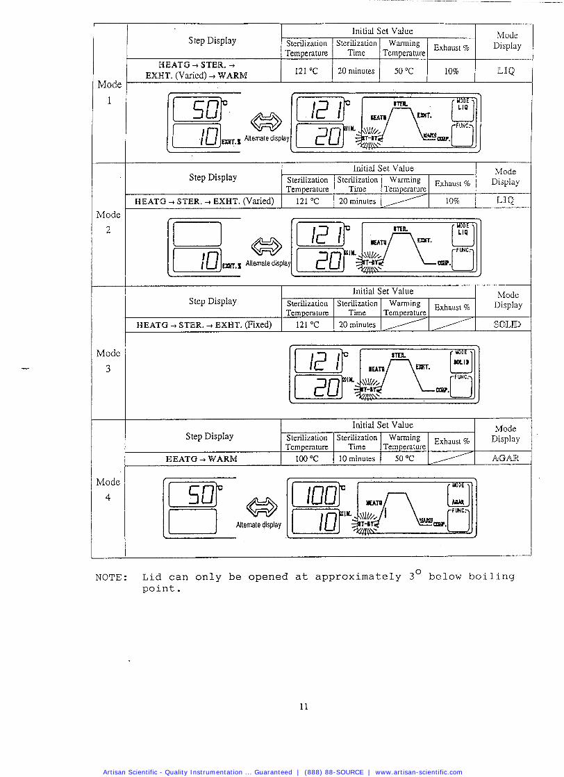
WEATG -+ STER. -+ EXHT. (Varied) -+WARM
Step Display
BEATG -+ STEW. -+ EXHT. (Varied)
Alternate display
IV IUUC
Display
ILJQ
Sterilization Temperature
12 1 OC
I
NOTE: Lid can only be opened at approximately 3 O below boiling point.
Mode ~ i ~ ~ l ~ ~
L ~ Q
Initial Set Value
Mode ~ i ~ ~ l a ~
XDLD
Step Display
HEATG -+ STER. -+ EXHT. (Fixed)
Sterilization Time
20 minutes
Mode Display
AGAR
Step Display
WEATG WARM
Exhaust %
10%
Initial Set Value
Warming Temperature
50 "C
Warming Temperature
/ Sterilization Temperatul~
121 OC
Sterilization Temperature
121 OC
Initial Set Value
Exhaust %
10%
Sterilization Time
20 minutes
Sterilization Time
20 minutes
W~rming Exhaust % Temperature
50 OC
Sterilization Temperature
100 OC
Sterilization Time
10 minutes
Warming Temperature
/ Exhaust %
/
Artisan Scientific - Quality Instrumentation ... Guaranteed | (888) 88-SOURCE | www.artisan-scientific.com
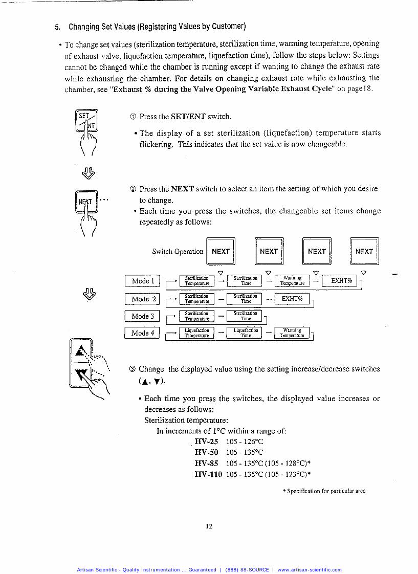
5. Changing Se t Values (Registering Values by Customer)
To change set values (sterilization temperature, sterilization time, warming temperature, opening of exhaust valve, liquefaction temperature, liquefaction time), follow the steps below: Settings cannot be changed while the chamber is running except if wanting to change the exhaust rate while exhausting the chamber. For details on changing exhaust rate while exhausting the chamber, see "Exhaust % during the Valve Opening Variable Exhaust Cycle" on pagel 8.
O Press the SETIENT switch.
The display of a set sterilization (liquefaction) temperature starts flickering. This indicates that the set value is now changeable.
O Press the NEXT switch to select an item the setting of which you desire to change.
* Each time you press the switches, the changeable set items change repeatedly as follows:
[mi W] Switch Operation NEXT
O Change the displayed value using the setting increaseldecrease switches
(A, v)- Each time you press the switches, the displayed value increases or decreases as follows: Sterilization temperature:
In increments of 1°C within a range of: HV-25 105 - 126°C
HV-50 105 - 135°C
EN-85 105 - 135OC (105 - 128OC)*
HV-110 105 - 135OC (105 - 123OC)*
* Specification for particular area
Artisan Scientific - Quality Instrumentation ... Guaranteed | (888) 88-SOURCE | www.artisan-scientific.com
@ Sterilization time: 1 minute increments within a range of 1-250 minute Liquefaction temperature: In increments of 1°C within a range of 60-
100°C Liquefaction time: 1 minute increments within a range of 1-60 minutes Warming temperature: 1°C increments w i t h a range of 45-60°C EXHT %: 1% increments within a range of 0-100% If you hold the switch down, the displayed value increases or decreases in 10 unit increments. When the displayed value exceeds the upper limit (lower limit), it returns to the lower limit (upper limit).
@ Press the SETLENT switch.
The changed value is stored, the display stops flickering and lights up.
\ I This completes the setting.
I- Canceling Changing the Set Values v If halfway you desire to cancel the setting change, press the MODE switch. The changed value is not stored, and the equipment returns to a standby state.
- NOTE
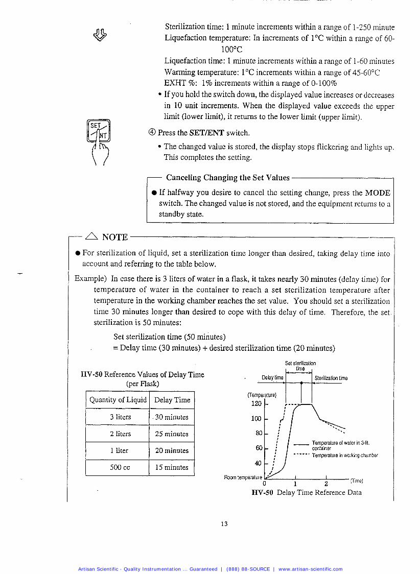
For sterilization of liquid, set a sterilization time longer than desired, taking delay time into account and referring to the table below.
Example) In case there is 3 liters of water in a flask, it takes nearly 30 minutes (delay time) for temperature of water in the container to reach a set sterilization temperature after temperature in the working chamber reaches the set value. You should set a sterilization time 30 minutes longer than desired to cope with this delay of time. Therefore, the set sterilization is 50 minutes:
Set sterilization time (50 minutes) = Delay time (30 minutes) + desired sterilization time (20 minutes)
Set sterilization
HV-50 Reference Values of Delay Time . , Dehy,time: ~~~= , Sterilization time
(per Flask)
Quantity of Liquid
3 liters
2 liters
1 liter
3 0 minutes
25 minutes
20 minutes Temperature in working chamber
HV-50 Delay Time Reference Data
Artisan Scientific - Quality Instrumentation ... Guaranteed | (888) 88-SOURCE | www.artisan-scientific.com
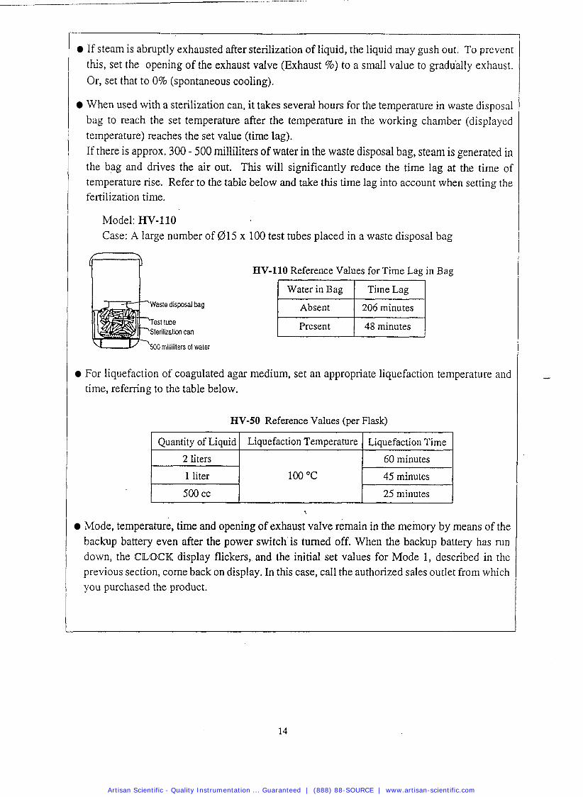
I If steam is abruptly exhausted after sterilization of liquid, the liquid may gush out. To prevenl this, set the opening of the exhaust valve (Exhaust %) to a small value to gradually exhaust.
I
Or, set that to 0% (spontaneous cooling).
When used with a sterilization can, it takes several hours for the temperature in waste disposal bag to reach the set temperature after the temperature in the working chamber (displayed temperature) reaches the set value (time lag). If there is approx. 300 - 500 milliliters of water in the waste disposal bag, steam is generated in the bag and drives the air out. This will significantly reduce the time lag at the time of temperature rise. Refer to the table below and take this time lag into account when setting the fertilization time.
Model: HV-110 Case: A large number of 0 1 5 x 100 test tubes placed in a waste disposal bag
7 7 HV-110 Reference Values for Time Lag in Bag
0 milliliters of water
For liquefaction of coagulated agar medium, set an appropriate liquefaction temperature and time, referring to the table below.
HV-50 Reference Values (per Flask)
Mode, temperature, time and opening of exhaust valve remain in the memory by means of the backup battery even after the power switch'is turned off. When the backup battery has run down, the CLOCK display flickers, and the initial set values for Mode 1, described in the previous section, come back on display. In this case, call the authorized sales outlet from which you purchased the product.
Quantity of Liquid
2 liters
1 liter
500 cc
Liquefaction Temperature
100 "C
Liquefaction Time
60 minutes
45 minutes
25 minutes
Artisan Scientific - Quality Instrumentation ... Guaranteed | (888) 88-SOURCE | www.artisan-scientific.com
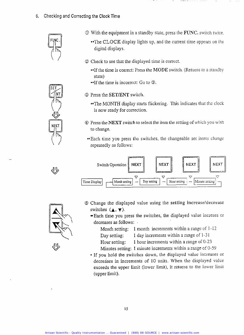
6. Checking and Correcting the Clock Time
@ With the equipment in a standby state, press the FUNC. switch twice.
The CILOCK display lights up, and the current time appears on the digital displays.
O Check to see that the displayed time is correct.
If the time is correct: Press the MODE switch. (Returns to a standby state) If the time is incorrect: Go to O.
O Press the SETENT switch.
The MONTH display starts flickering. This indicates that the clock is now ready for correction.
0 Press the NEXT switch to select the item the setting of which you wish
to change.
Each time you press the switches, the changeable set items change repeatedly as follows:
Switch Operation
O Change the displayed value using the setting increaseldecrease switches (A, y ) .
Each time you press the switches, the displayed value increses or decreases as follows: .
Month setting: 1 month increments within a range of 1-12 Day setting: 1 day increments within a range of 1-3 1 Hour setting: 1 hour increments within a range of 0-23 Minutes setting: 1 minute increments within a range of 0-59
If you hold the switches down, the displayed value increases or decreases in increments of 10 units. When the displayed value exceeds the upper limit (lower limit), it returns to the lower limit (upper limit).
Artisan Scientific - Quality Instrumentation ... Guaranteed | (888) 88-SOURCE | www.artisan-scientific.com
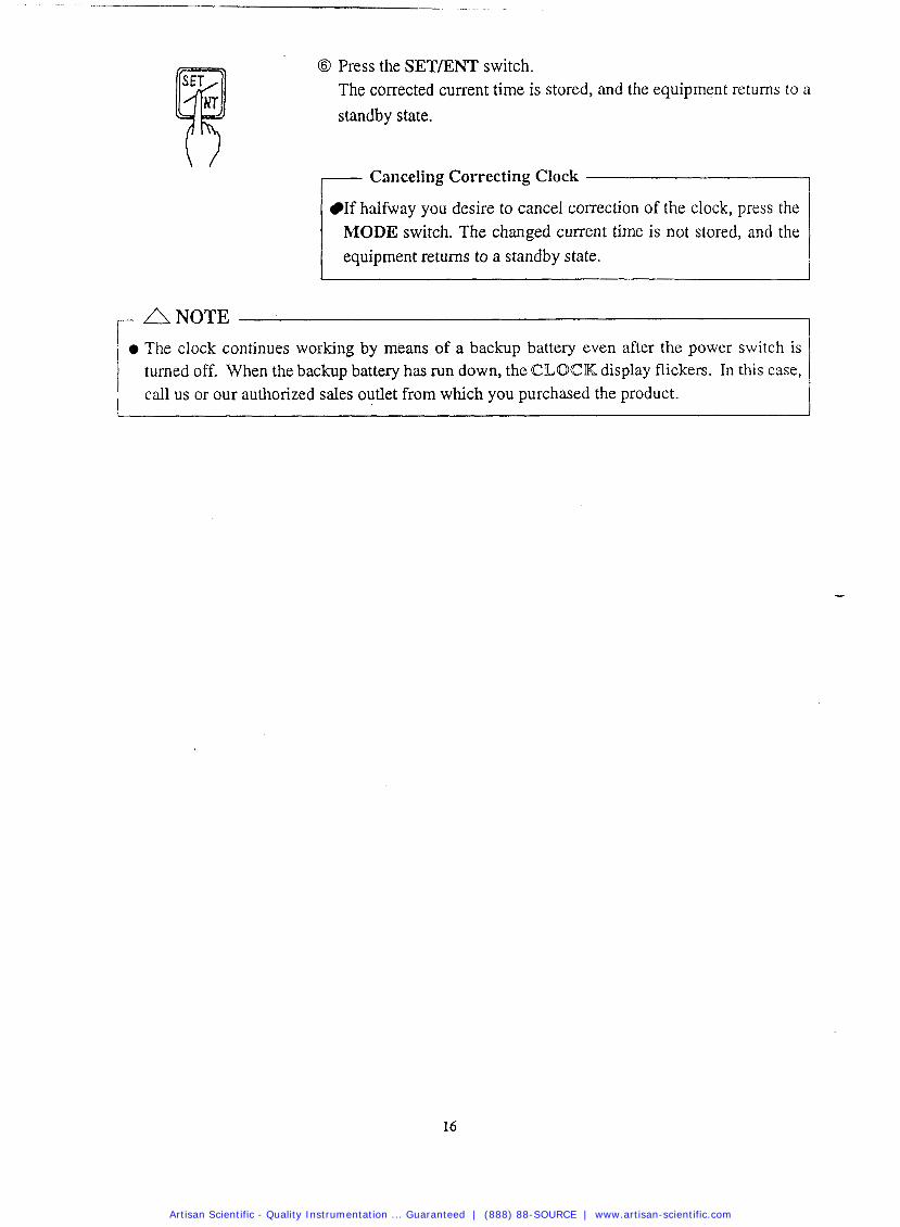
8 Press the SETIENT switch. The corrected current time is stored, and the equipment returns to a
standby state.
Canceling Correcting Clock
If halfway you desire to cancel correction of the clock, press the MODE switch. The changed current time is not stored, and the equipment returns to a standby state.
r /\ NOTE
The clock continues working by means of a backup battery even after the power switch is turned off, When the backup battery has run down, the QIILOCK display flickers. In this case, call us or our authorized sales outlet from which you purchased the product.
Artisan Scientific - Quality Instrumentation ... Guaranteed | (888) 88-SOURCE | www.artisan-scientific.com
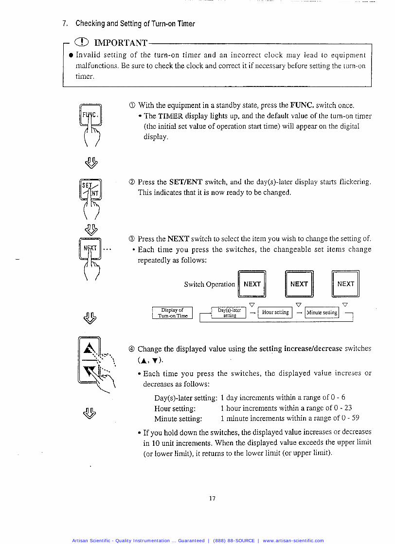
7. Checking and Setting of Turn-on Timer
a IMPORTANT 0 Invalid setting of the turn-on timer and an incorrect clock may lead to equipment i malfunctions. Be sure to check the clock and correct it if necessary before setting the turn-on I timer
With the equipment in a standby state, press the FUNC. switch once. The TIMER display lights up, and the default value of the turn-on timer (the initial set value of operation start time) will appear on the digital display.
Press the SETIENT switch, and the day(s)-later display starts flickering. This indicates that it is now ready to be changed.
Press the NEXT switch to select the item you wish to change the setting of. Each time you press the switches, the changeable set items change repeatedly as follows:
v v
Turn-on Time
Change the displayed value using the setting increaseldecrease switches
(A> v). Each time you press the switches, the displayed value increses or decreases as follows:
Day(s)-later setting: 1 day increments within a range of 0 - 6 Hour setting: 1 hour increments within a range of 0 - 23 Minute setting: 1 minute increments within a range of 0 - 59
If you hold down the switches, the displayed value increases or decreases in 10 unit increments. When the displayed value exceeds the upper limit (or lower limit), it returns to the lower limit (or upper limit).
Artisan Scientific - Quality Instrumentation ... Guaranteed | (888) 88-SOURCE | www.artisan-scientific.com
Example of Setting:
When you desire to start operation at 11:30 p.m. today, your setting
should be as follows: Day(s)-later setting = 0, Hour setting = 23, Minute setting = 30 When you desire to start operation at 5:00 a.m. the day after tomorrow, your setting should be as follows: Day(s)-later setting = 2, Hour setting = 5, Minute setting = 0
O Press the SET/ENT switch.
The set turn-on time is stored, and the equipment returns to the standby state with the Tl[MIEK display on. (If you enter a time before the current time, an electronic alarm sounds and display of the day(s)-later setting starts flickering. In this case, check the turn-on time you set, and correctly set the turn-on timer again.
Canceling Setting Turn-on Timer
If halfway you desire to cancel setting the turn-on timer, press the MODE switch. The changed turn-on time will not be stored, and the equipment returns to the standby state.
- A NOTE
0 Operation will not start at the set time unless theSTART/STOP switch has been pressed, even after completion of setting the turn-on timer.
0 To cancel a time set on the turn-on timer, turn off the power switch, and the set turn-on time will be ignored. A turn-on timer setting is effective for only one operation.
.If operation is stopped before the reaching the set start time, the start time setting is kept unchanged.
Artisan Scientific - Quality Instrumentation ... Guaranteed | (888) 88-SOURCE | www.artisan-scientific.com
8. Starting Operation
O Check again to see that the water level in the exhaust bottle is between the HIGH and LOW levels.
... If above the HIGH level See "2. Draining Working Chamber" on page 27.
... If below the LOW setting See "2. Installation Procedure O" on page 5.
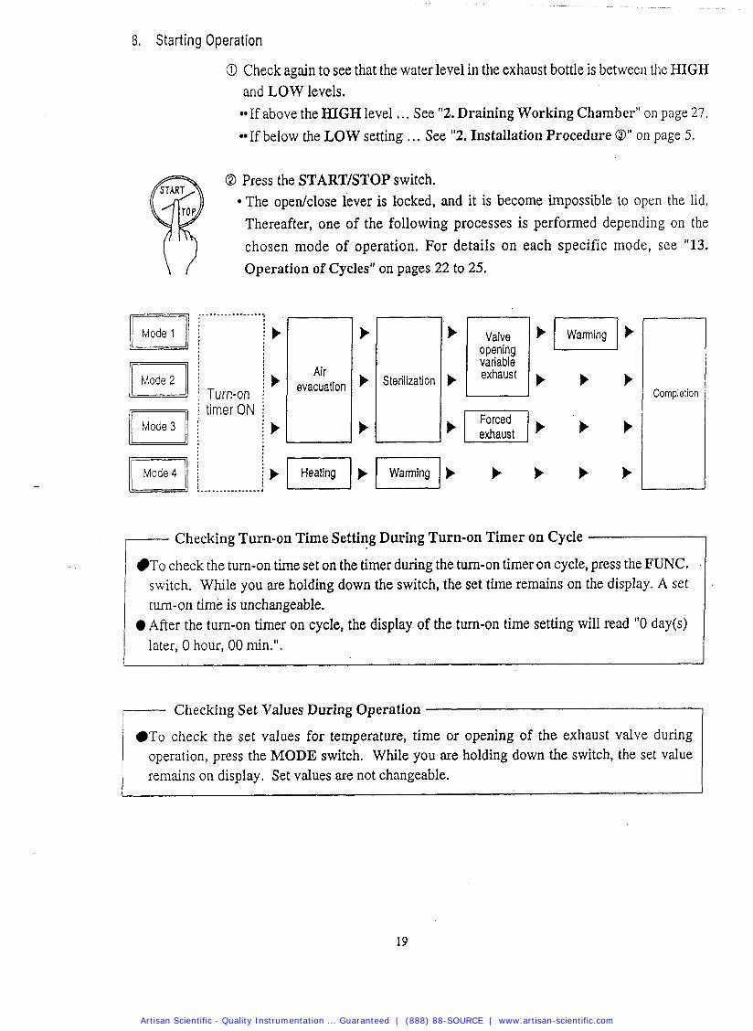
O Press the STARTISTOP switch. The open/close lever is locked, and it is become impossible to open the lid. Thereafter, one of the following processes is performed depending on the
chosen mode of operation. For details on each specific mode, see "13. \ Operation of Cycles" on pages 22 to 25.
t
evacuation b
b
i ' ) I I b F l b Heating b t b b i L................ 4
Complelion
I Checking Turn-on Time Setting During Turn-on Timer on Cycle I
r Checking Set Values During Operation
To check the turn-on time set on the timer during the turn-on timer on cycle, press the FUNC. .
switch. While you me holding down the switch, the set time remains on the display. A set turn-on time is unchangeable.
0 After the turn-on timer on cycle, the display of the turn-on time setting will read "0 day(s) later, 0 hour, 00 rnin.".
To check the set values for temperature, time or opening of the exhaust valve during operation, press the MODE switch. While you are holding down the switch, the set value remains on display. Set values are not changeable.
.
Artisan Scientific - Quality Instrumentation ... Guaranteed | (888) 88-SOURCE | www.artisan-scientific.com
- Exhaust % During the Valve Opening Variable Exhaust Cycle
O Press the SETIENT switch.
The display of opening of the exhaust % display starts flickering, and indicates that it is now ready to be changed.
O Change the numeric value using the set value increasddecrease switches (A, .I(.). Each time you press the switches, the displayed value increases or decreases in 1% increments within a range of 1-100%. If you hold down the switches, the displayed value increases or decreases in 10% increments. When the displayed value exceeds the upper limit (or lower limit), it returns to the lower limit (or upper limit).
O Press the SETENT switch. The changed value will be stored', and the display stops flickering and lights up again. The exhaust valve is controlled according to the set exhaust %. (The stored numerical value is also effective for the next operation.)
Artisan Scientific - Quality Instrumentation ... Guaranteed | (888) 88-SOURCE | www.artisan-scientific.com
9. Unloading
A WARNING
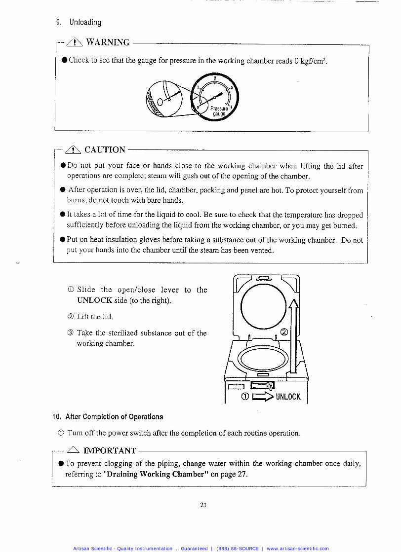
Check to see that the gauge for pressure in the working chamber reads 0 kgf/cm2.
- A CAUTION
D o not put your face or hands close to the working chamber when lifting the lid after operations are complete; steam will gush out of the opening of the chamber.
After operation is over, the lid, chamber, packing and panel are hot. To protect yourself from bums, do not touch with bare hands.
It takes a lot of time for the liquid to cool. Be sure to check that the temperature has dropped sufficiently before unloading the liquid from the working chamber, or you may get burned.
Put on heat insulation gloves before taking a substance out of the working chamber. Do not put your hands into the chamber until the steam has been vented.
O Slide the open/close lever to the UNLOCK side (to the right).
O Lift the lid.
O Take the sterilized substance out of the working chamber.
10. After Completion of Operations
O Turn off the power switch after the completion of each routine operation.
A IMPORTANT T o prevent clogging of the piping, change water within the working chamber once daily, r refemng to "Draining Working Chamber" on page 27.
Artisan Scientific - Quality Instrumentation ... Guaranteed | (888) 88-SOURCE | www.artisan-scientific.com
11. To Interrupt Operation
A NOTE
If operation is interrupted during the sterilization of liquid, the liquid may overflow into the worlung chamber. I
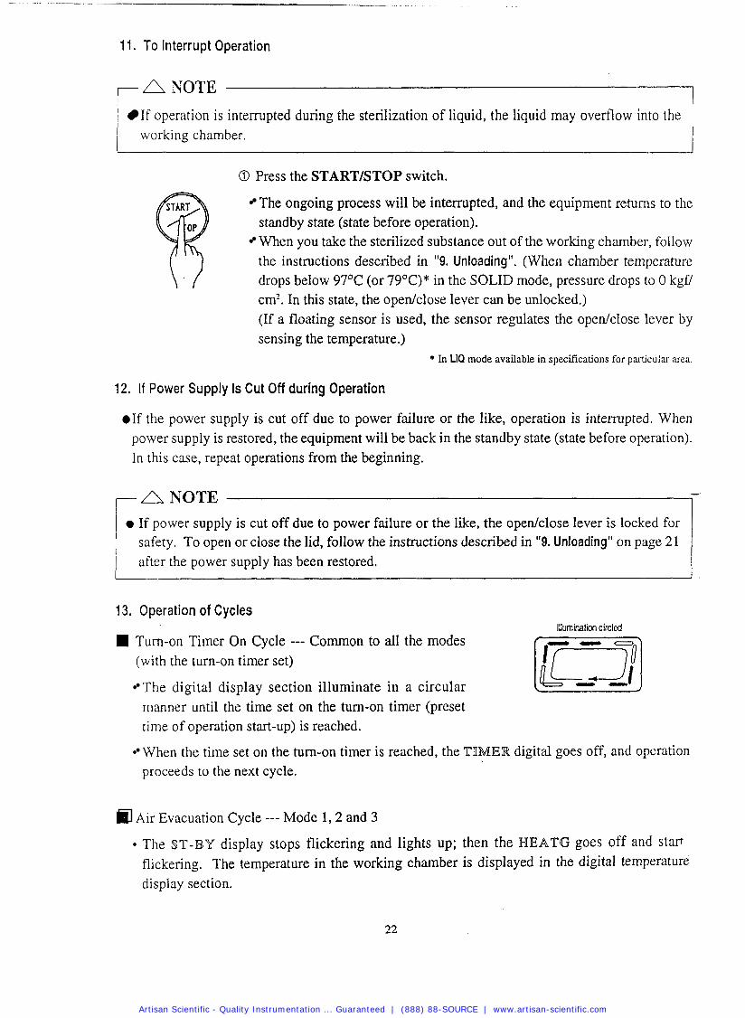
O Press the STARTISTOP switch.
The ongoing process will be interrupted, and the equipment returns to the standby state (state before operation). When you take the sterilized substance out of the working chamber, follow the instructions described in "9. Unloading". (When chamber temperature drops below 97'C (or 7g°C)* in the SOLID mode, pressure drops to 0 kgfl cm?. In this state, the opedclose lever can be unlocked.) (If a floating sensor is used, the sensor regulates the open/close lever by sensing the temperature.)
* In LIQ mode available in specifications for particular area.
12. If Power Supply Is Cut Off during Operation
.If the power supply is cut off due to power failure or the like, operation is interrupted. When power supply is restored, the equipment will be back in the standby state (state before operation). In this case, repeat operations from the beginning.
- ,--- A NOTE 1 0 If power supply is cut off due to power failure or the like, the opedclose lever is locked for
safety. To open or close the lid, follow the instructions described in "9. Unloading" on page 21 after the power supply has been restored.
13. Operation of Cycles Illumination circled
Turn-on Timer On Cycle --- Common to a11 the modes (with the turn-on timer set)
The digital display section illuminate in a circular manner until the time set on the turn-on timer (preset time of operation start-up) is reached.
When the time set on the turn-on timer is reached, the TIMER digital goes off, and operation proceeds to the next cycle.
Air Evacuation Cycle --- Mode 1,2 and 3
The ST-BY display stops flickering and lights up; then the BIEATG goes off and start flickering. The temperature in the working chamber is displayed in the digital temperature display section.
Artisan Scientific - Quality Instrumentation ... Guaranteed | (888) 88-SOURCE | www.artisan-scientific.com
Any air remaining in the working chamber makes the temperature distribution in the chamber uneven. This hinders temperature rise (sterilization). To cope with this, a microcomputer-con-
trolled automatic exhaust valve vents virtually 100% of the air.
Temperature rises until a set sterilization temperature (pressure) is reached.
After the set sterilization temperature is attained, the WIEATG stops flickering and lights up. Operation proceeds to the next step.
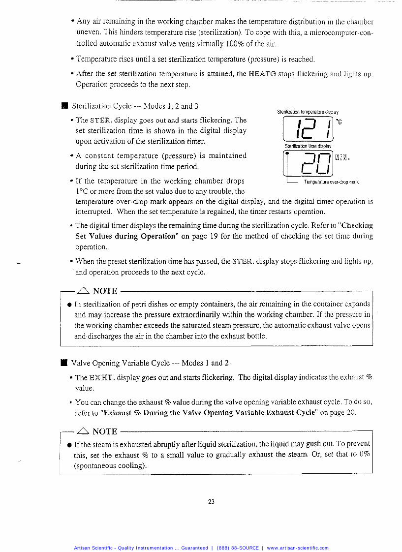
81 Sterilization Cycle --- Modes 1, 2 and 3 Sterilization temperature display
The STIER. display goes out and starts flickering. The set sterilization time is shown in the digital display upon activation of the sterilization timer.
[,I " Sterilization lime display
A constant temperature (pressure) is maintained during the set sterilization time period.
If the temperature in the working chamber drops Temperature over-drop ma&
1 "C or more from the set value due to any trouble, the temperature over-drop mark appears on the digital display, and the digital timer operation is interrupted. When the set temperahre is regained, the timer restarts operation.
The digital timer displays the remaining time during the sterilization cycle. Refer to "Checking Set Values during Operation" on page 19 for the method of checking the set time during operation.
When the preset sterilization time has passed, the STIER. display stops flickering and lights up, and operation proceeds to the next cycle.
0 In sterilization of petri dishes or empty containers, the air remaining in the container expands and may increase the pressure extraordinarily within the working chamber. If the pressure in the working chamber exceeds the saturated steam pressure, the automatic exhaust valve opens and.discharges the air in the chamber into the exhaust bottle.
Valve Opening Variable Cycle --- Modes 1 and 2 .
The IEXWT. display goes out and starts flickering. The digital display indicates the exhaust % value.
You can change the exhaust % value during the valve opening variable exhaust cycle. To do so, refer to "Exhaust % During the Valve Opening Variable Exhaust Cycle" on page 20
- A NOTE
If the steam is exhausted abruptly after liquid sterilization, the liquid may gush out. To prevent this, set the exhaust % to a small value to gradually exhaust the steam. Or, set that to 0% (spontaneous cooling).
Artisan Scientific - Quality Instrumentation ... Guaranteed | (888) 88-SOURCE | www.artisan-scientific.com
When the pressure in the working chamber falls below 0.1 kgf/cm2, the exhaust valve is fully
opened.
When the temperature in the working chamber (or the temperature resistered by the floating sensor, if used) falls to 97°C (or 7g°C)*, the EWWT. display stops flickering and lights up. The display of opening of the exhaust valve (exhaust %) disappears from the digital display, and operation proceeds to the next cycle.
* Specifications for particular area.
Forced Exhaust Cycle --- Mode 3
The IEXWT, display goes out and starts flickering, and the automatic exhaust valve is fully opened. When the temperature in the working chamber falls to 97"C, the IEXWT. display stops flickering and lights up, and operation proceeds to the next cycle.
II Heating Cycle --- Mode 4
The ST-BY display stops flickering and lights up, and the WIEATG display goes out and starts flickering. The digital display indicates the temperature in the working chamber.
Temperature rises until a set liquefaction temperature is reached.
After the set temperature is reached, a set liquefaction time is shown on the digital display upon the activation of the liquefaction timer.
The digital timer displays the remaining time during the heating cycle. Refer to "Checking Set - Values during Operation" on page 19 for the method of checking the set time during operation.
When the time preset for liquefaction has passed, the HEATING LED stops flickering and lights up, and operation proceeds to the next cycle.
Warming Cycle --- Modes 1 and 4
The WARM display goes out and starts flickering.
When the temperature in the working chamber falls to a set incubation temperature, the electronic alarm gives a beeping sound.
When 20 hr. (fixed) have passed after the temperature drops to the set incubation temperature, the WARM display stops flickering and.lights up, and operation proceeds to the next cycle.
-A NOTE After the warming time (20 hr.) has passed, the working chamber is not heated; temperature in the chamber falls to room temperature, and the remaining agar medium, if any, in the chamber will be coagulated.
a When you take a sterilized substance out of the working chamber during the warming cycle, press the START6TOP switch to stop operation. Refer to "9. Unloading" on page 21.
Artisan Scientific - Quality Instrumentation ... Guaranteed | (888) 88-SOURCE | www.artisan-scientific.com
Completion Cycle --- Common to all the Modes
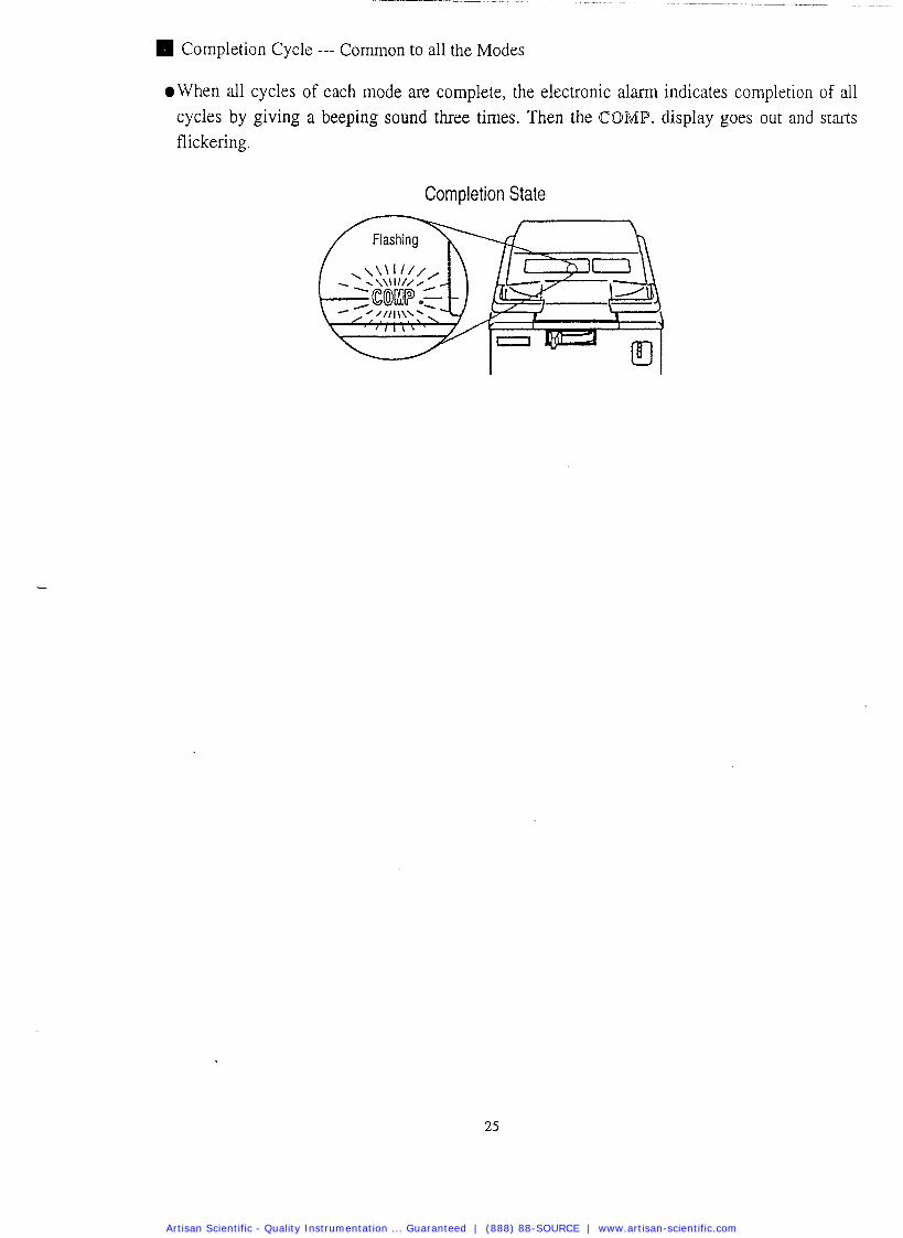
@When all cycles of each mode are complete, the electronic alarm indicates completion of all cycles by giving a beeping sound three times. Then the COMP. display goes out and starts flickering.
Completion State
Artisan Scientific - Quality Instrumentation ... Guaranteed | (888) 88-SOURCE | www.artisan-scientific.com
Chapter 4. Maintenance and Service
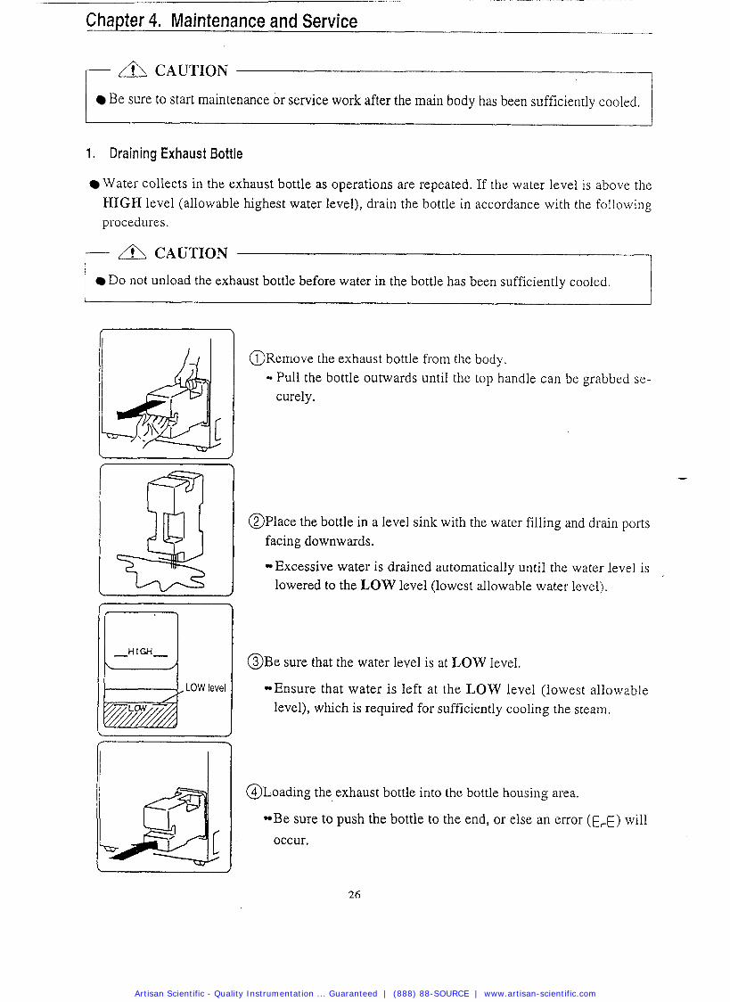
Be sure to start maintenance or service work after the main body has been sufficiently cooled. r I cAuT1oN
1. Draining Exhaust Bottle
Water collects in the exhaust bottle as operations are repeated. If the water level is above the HIGH level (allowable highest water level), drain the bottle in accordance with the following procedures.
Do not unload the exhaust bottle before water in the bottle has been sufficiently cooled. ; A cAuTroN
level
O ~ e m o v e the exhaust bottle from the body. Pull the bottle outwards until the top handle can be grabbed se- curely.
@ ~ l a c e the bottle in a level sink with the water filling and drain ports facing downwards.
Excessive water is drained automatically until the water level is lowered to the LOW level (lowest allowable water level).
@ ~ e sure that the water level is at LOW level.
Ensure that water is left at the LOW level (lowest allowable level), which is required for sufficiently cooling the steam.
@ ~ o a d i n ~ the exhaust bottle into the bottle housing area.
Be sure to push the bottle to the end, or else an error (I=,€) will
occur.
Artisan Scientific - Quality Instrumentation ... Guaranteed | (888) 88-SOURCE | www.artisan-scientific.com
- - - - - - - ---
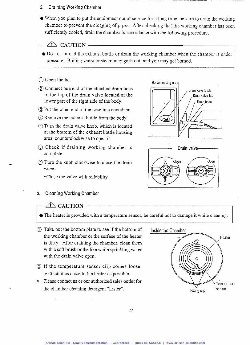
2. Draining Working Chamber
When you plan to put the equipment out of service for a long time, be sure to drain the working chamber to prevent the clogging of pipes. After checking that the working chamber has been sufficiently cooled, drain the chamber in accordance with the following procedure.
r A CAUTION
Do not unload the exhaust bottle or drain the working chamber when the chamber is under pressure. Boiling water or steam may gush out, and you may get burned.
@ Open the lid.
@ Connect one end of the attached drain hose to the tap of the drain valve located at the lower part of the right side of the body.
@ Put the other end of the hose in a container.
@ Remove the exhaust bottle from the body.
@ Turn the drain valve knob, which is located at the bottom of the exhaust bottle housing area, counterclockwise to open it.
@ Check if draining working chamber is complete.
@ Turn the knob clockwise to close the drain valve.
Close the valve with reliability.
Bottle housing areal
3. Cleaning Working Chamber
The heater is provided with a temperature sensor, be careful not to damage it while cleaning. r cAuT1oN
@ Take out the bottom plate to see if the bottom of Inside the Chamber the working chamber or the surface of the heater Heater is dirty. After draining the chamber, clean them with a soft brush or the like while sprinkling water with the drain valve open.
@ If the temperature sensor clip comes loose, reattach it as close to the heater as possible.
Please contact us or our authorized sales outlet for
the chamber cleaning detergent "Lister". V
Fixing clip
Artisan Scientific - Quality Instrumentation ... Guaranteed | (888) 88-SOURCE | www.artisan-scientific.com
3 . Body Service
, a IMPORTANT
Do not use benzine or thinner to clean the body. Also make sure that the volatile substances
such as insecticides do not come into contact with the body as these substances may deteriorate
[he body or strip its paint.
@ Gently wipe stains from the body with a soft cloth. To remove stubborn stains, wring a cloth moistened with neutral detergent diluted with water, and wipe off the stains with it. Wipe off any moisture with a dry cloth.
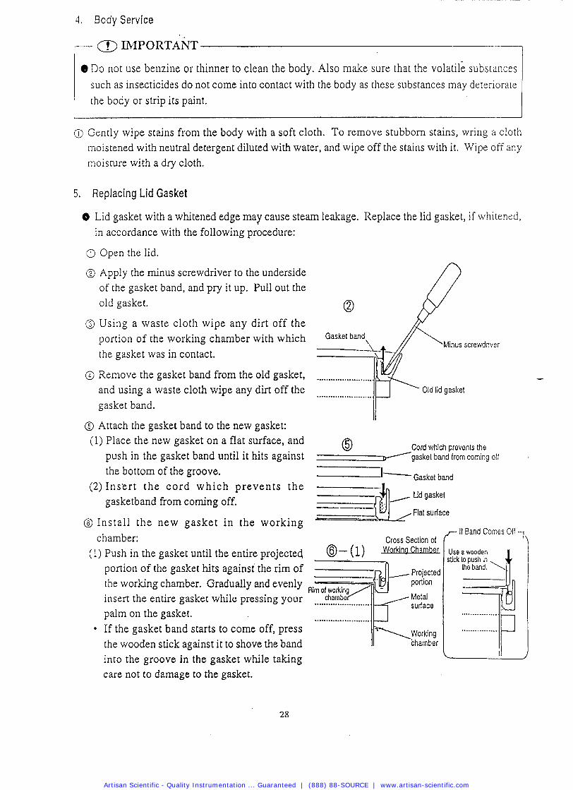
5. Replacing Lid Gasket
8 Lid gasket with a whitened edge may cause steam leakage. Replace the lid gasket, if whitened, in accordance with the following procedure:
@ Open the lid.
@ Apply the minus screwdriver to the underside of the gasket band, and pry it up. Pull out the old gasket.
@ Using a waste cloth wipe any dirt off the portion of the working chamber with which the gasket was in contact.
@ Remove the gasket band from the old gasket, and using a waste cloth wipe any dirt off the gasket band.
@ Attach the gasket band to the new gasket: (1) Place the new gasket on a flat surface, and 0 Cord which prevents the
push in the gasket band until it hits against g a s k e t band from coming off
the bottom of the groove. I- Gasket band (2 ) In se r t the c o r d wh ich p reven t s t he
gasketband from coming off.
@ Install the new gaske t in the working chamber:
(1) Push in the gasket until the entire projected portion of the gasket hits against the rim of the working chamber. Gradually and evenly insert the entire gasket while pressing your palm on the gasket.
* If the gasket band starts to come off, press the wooden stick against it to shove the band into the groove in the gasket while taking care not to damage to the gasket.
Cross Section of
@-(I) - ,_, Projecte
portion
charnbe , Metal ........................ surface ........................
,,-- I f Band Comes 011 --:
Use a wooden stick lo push in
R e band. \ / t
Artisan Scientific - Quality Instrumentation ... Guaranteed | (888) 88-SOURCE | www.artisan-scientific.com
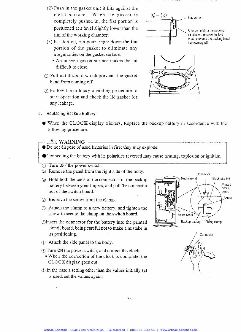
(2) Push in the gasket unit it hits against the metal surface . When the gasket is @- (2)
d- Flat porton
completely pushed in, the flat portion is
positioned at a level slightly lower than the ......................... After compleimg the packrng
rim of the working chamber. ........................ installation, remove the ford which prevents the packing band
(3) In addition, run your finger down the flat from coming off.
portion of the gasket to eliminate any irregularities on the gasket surface. An uneven gasket surface makes the lid I I difficult to close.
a Pull out the cord which prevents the gasket band from coming off.
@ Follow the ordinary operating procedure to start operation and check the lid gasket for I
any leakage.
6. Replacing Backup Battery
0 When the CILOC K display flickers, Replace the backup battery in accordance with the following procedure.
0 Do not dispose of used batteries in fire; they may explode. r / Connecting the battery with its polarities reversed may cause heating, explosion or ignition. I 1 i
@ Turn OFF the power switch. @ Remove the panel from the right side of the body.
Connector
@ Hold both the ends of the connector for the backup battery between your fingers, and pull the connector out of the switch board.
@ Remove the screw from the clamp.
@ Attach the clamp to a new battery, and tighten the screw to secure the clamp on the switch board.
@Insert the connector for the battery into the printed circuit board, being careful not to make a mistake in its positioning. / connector
Attach the side panel to the body.
@ Turn ON the power switch, and correct the clock. When the correction of the clock is complete, the CLOCK display goes out.
@ In the case a setting other than the values initially set is used, set the values again.
Artisan Scientific - Quality Instrumentation ... Guaranteed | (888) 88-SOURCE | www.artisan-scientific.com
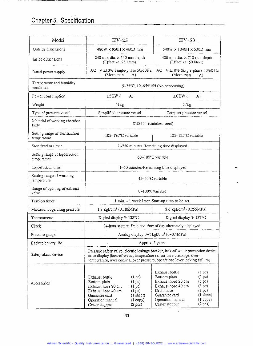
Chapter 5. Specification
Outside dimensions
HV-50 Model
Inside dimensions
Rated power supply
Temperature and humidity conditions
HV-25
1 480W x 950H x 460D mm
240 mm dia. x 550 rnm depth (Effective: 25 liters)
AC V f 10% Single-phase 50160Hz (More than A)
5-3S°C, 10-85%RH (No condensing)
540W x 1040H x 530D ~ n m
300 ~nrn dia. x 710 rnm depth (Effective: 50 liters)
AC V f 10% Single-phase 50/60 H (More than A)
Power consumption
Weight
Type of pressure vessel
41kg
~irn~l i ' f ied pressure vessel
Material of working chamber MY
57kg
Compact pressure vessel
SUS304 (stainless steel)
Setting range of sterilization temperature
105-126OC variable 105-135°C variable
Sterilization timer
Setting range of liquefaction temperature
1-250 minutes.Remaining lime displayed.
60-100°C variable
Liquefaction timer 1-60 minutes.Remaining time displayed
Setting range of warming temperature 45-60°C variable
Range of opening of exhaust valve 0-100% variable
Turn-on timer
Maximum oprating pressure
1 min. - 1 week 1ater:Start-up time to be set.
1.9 kgf/cm2 (0.186MPa)
Clock
2.6 kgf/cm2 (0.255MPa)
Digital display 5-128OC
Pressure gauge
Digitd display 5-137°C
Backup battery life
24-hour system. Date and time of day alternately displayed.
Analog display 0-4 kgf/c1n2 (0-0.4MPa)
Approx. 5 years
Pressure safety valve, electric leakage breaker, lack-of-water prevention device error display (lack-of-water, temperature sensor wire breakage, over- temperature, over cooling, over pressure, open/close lever locking failure)
I
Safety alarm device
I Exhaust bottle (1 PC)
Accessories Exhaust bottle (1 PC) Bottom plate (1 PC) Exhaust hose 20 cm (I PC)
Bottom plate (1 pc) Exhaust hose 20 cm (1 pc) Exhaust hose 40 cm (1 pc)
Exhaust hose 40 crn (1 pc) Guarantee card (1 sheet) Operation manual (1 copy) Caster stopper (2 PCS)
Drain hose (1 PC) Guarantee card (1 sheet) Operation manual (1 COPY)
Caster stopper (2 PC$)
Artisan Scientific - Quality Instrumentation ... Guaranteed | (888) 88-SOURCE | www.artisan-scientific.com
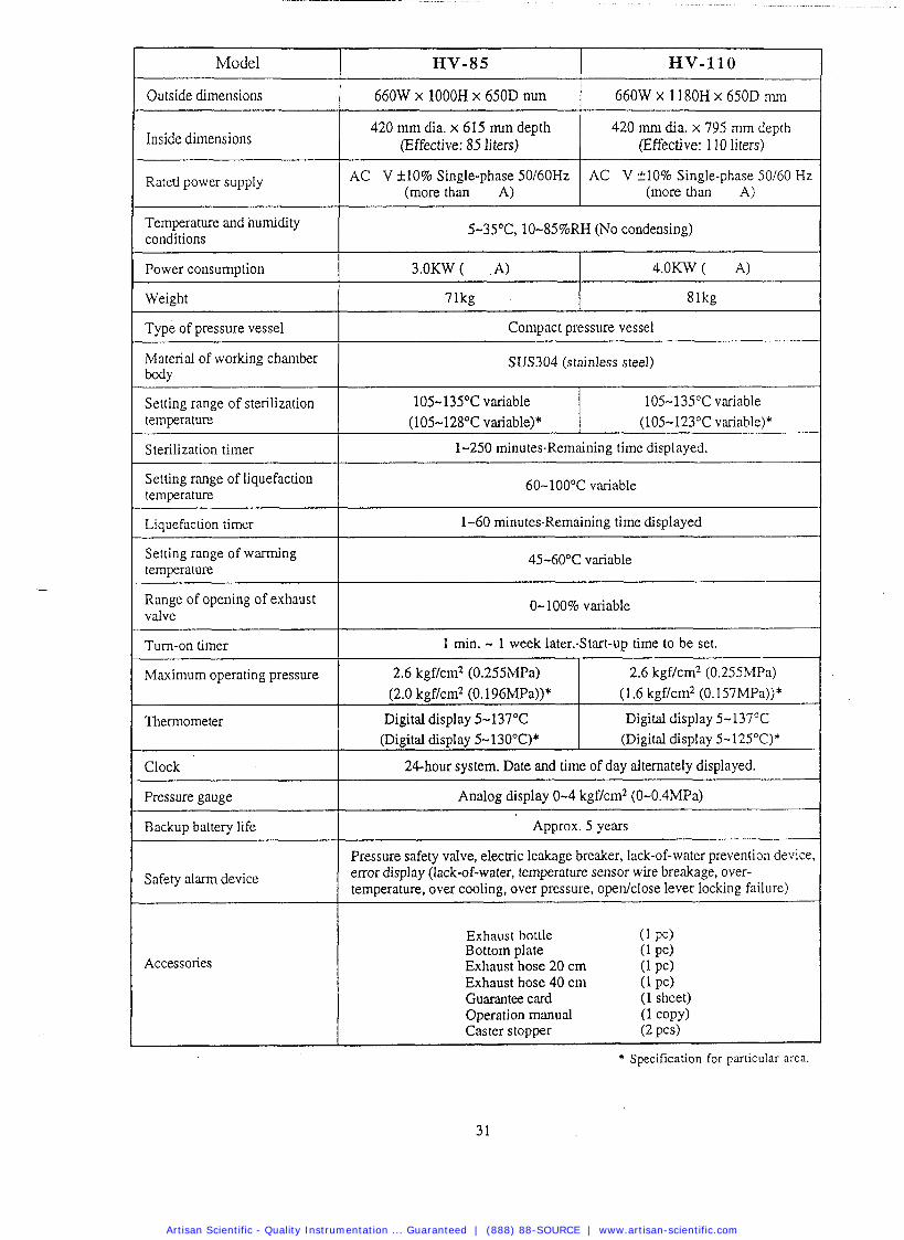
I Model
I Outside dimensions
Inside dimensions
Rated power supply
420 rnrn dia. x 615 mm depth I (Effective: 85 liters) 420 mrn dia. x 795 rnm depth
(Effective: 1 10 iiters)
Temperature and humidity conditions I
AC V f 10% Single-phase 50160Hz (more than A)
5-35"C, 10-85%RH (No condensing)
AC V f 10% Single-phase 50160 Hz (more than A)
I
Weight
Material of working chamber I MY
4.OKW ( A) Power consumption
~ p e of pressure vessel
SUS304 (stainless steel)
3.OKW ( ,A)
71kg
Compact pressure vessel
81kg
I
I
I Sterilization timer I 1-250 minutes.Remaining time displayed.
temperature
Setting range of liquefaction temperature I --
105-135°C variable Setting range of sterilization
60-100°C variable
105-135OC variable (105-128°C variable)* (105-123°C variable)*
Setting range of warming temperature I Liquefaction timer
45-60°C variable
1-60 minutes-Remaining time displayed
Range of opening of exhaust I valve
I
0-100% variable -- --
Turn-on timer
Maximum operating pressure
Thermometer
Clock
Safety alarm device
Pressure gauge
Backup battery life
Pressure safety valve, electric leakage breaker, lack-of-water prevention device enor display (lack-of-water, temperature sensor wire breakage, over- temperature, over cooling, over pressure, openklose lever locking failure)
1 min. - 1 week 1ater:Start-up time to be set.
Analog display 0-4 kgf/cm2 (0-0.4MPa)
Approx. 5 years
2.6 kgf/cm2 (0.255MPa) (2.0 kgf/cm2 (0.196MPa))*
Digital display 5-137OC (Digital display 5-130°C)*
2.6 kgf/cm2 (0.255MPa) (1.6 kgf/cm2 (0.157MPa))*
Digital display 5-137°C (Digital display 5-125"C)*
Accessories
24-hour system. Date and time of day alternately displayed.
Exhaust bottle ( 1 PC) Bottom plate (1 PC) Exhaust hose 20 cm (1 PC) Exhaust hose 40 cm (1 pcf Guarantee card (1 sheet) Operation manual (1 COPY) Caster stopper (2 PCS)
* Specification for particular area.
Artisan Scientific - Quality Instrumentation ... Guaranteed | (888) 88-SOURCE | www.artisan-scientific.com
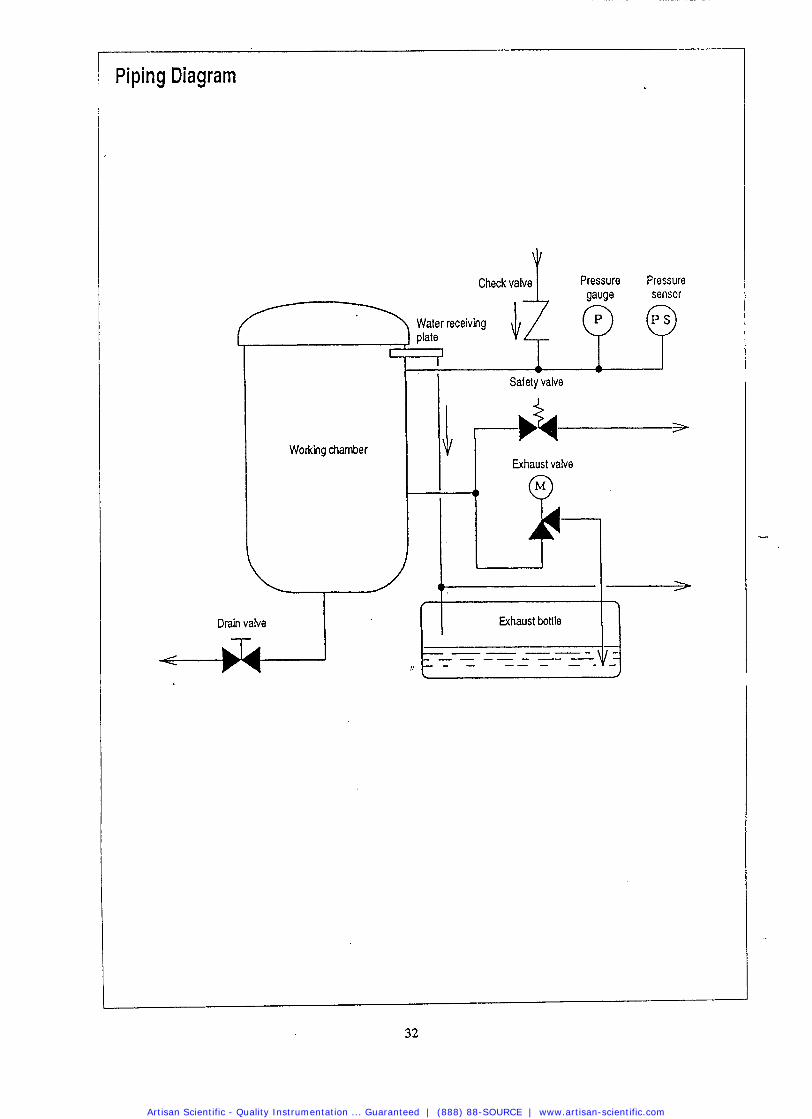
Piping Diagram
Pressure Pressure gauge sensor
Working chamber
I
Drain valve -
Safety valve
Exhaust valve
41
I
Exhaust bottle fl
Artisan Scientific - Quality Instrumentation ... Guaranteed | (888) 88-SOURCE | www.artisan-scientific.com
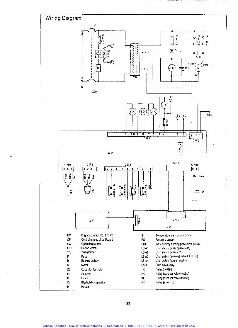
Wiring Diagram
U U L
DP CP SW ELB m F B M
Disphy printed circuit board Control printed circuit board Operation switch Power switch Transformer Fuse Backup battery Motor
S1 PS EGO LSWl LSW2 LSW3 LSW4 SSR
Temperalure sensor for cmtrol Pressure sensor Water empty heating preventive device Limit switch (lever opedclose) Lima switch (lever lock) Llmit switch (exhaust vake full close) Limit swlch (bottle housing) Solid-state relay
C2 Capacitor for motor 1 X Relay (heater) SL Solenoid 2X Relay (exhaust valve closing) D P i e 3X Relay (exhaust valve opening) C 1 Eleclrolylic capacitor 4X Relay (solenoid) H Heater
Artisan Scientific - Quality Instrumentation ... Guaranteed | (888) 88-SOURCE | www.artisan-scientific.com
Chapter 6. In the Event of Suspected Failure
1. Error Detection (Alarming) Operation
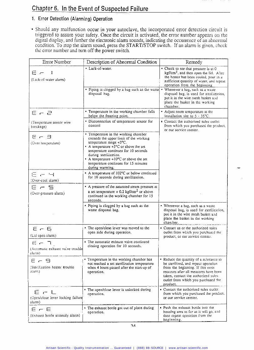
Should any malfunction occur in your autoclave, the incorporated error detection circuit is triggered to assure your safety. Once the circuit is activated, the error number appears on the digital display, and further the electronic alarm sounds, indicating the occurrence of an abnormal condition. To stop the alarm sound, press the STARTISTOP switch. If an alarm is given, check the error numberhnd turn off the switch.
-
Error Number
(Lack-of-water alarm)
(Temperature sensor wire breakage)
E r - 3 (Over temperature)
:Over-cool alarm)
E r S :Over-pressure alarm)
Lid open alarm)
E r - 1 .4utomatic exhaust valve troubl~ ~ l a r r n )
E r - 9 Sterilization heater trouble ~larm)
€ f- 'L Open/close lever locking failurc ~larm)
E r E Exhaust bottle anomaly alarm)
Description of Abnormal Condition
Piping is clogged by a bag such as the wast disposal bag.
Temperature in the working chamber falls below the freezing point.
Disconnection of temperature sensor for control
Temperature in the working chamber exceeds the upper limit of the working temperature range +3OC. A temperature +5OC or above the set temperature continues for 10 seconds during sterilization. A temperature +lO°C or above the set temperature continues for 15 minutes during warming.
A temperature of 102OC or below continued for 10 seconds during sterilization.
A pressure of the saturated steam pressure at a set temperature + 0.2 kgf/cm2 or above continued in the working chamber for 15 seconds.
Piping is clogged by a bag such as the waste disposal bag.
The opedclose lever was moved to the open side during operation.
The automatic exhaust valve continued closing operation for 10 seconds.
Temperature in the working chamber has not reached a set sterilization temperature when 4 hours passed after the start-up of operation.
* The openfclose lever is unlocked during operation.
* The exhaust bottle got out of place during operation.
Whenever a bag, such as a waste disposal bag, is used for sterilization, put it in the wire mesh basket and place the basket in the working chamber. Contact us or the authorized sales outlet from which you purchased the product, or our service cemter.
1
Reduce the quantity of a substance to be sterilized, and repeat operation from the beginning. If this error reoccurs after all measures have been [&en, contact the authorized sales outlet from which you purchased the product. Contact the authorized sales outlet from which you purchased the product, or our service cemter.
Remedy Check to see that pressure is at 0 kgf/cm2, and then open the lid. After the heater has been cooled. pour in a sufficient quantity of water, and repeat operation from the beginning Whenever a bag, such as a waste disposal bag, is used for srerilizntion. put it in the wire mesh basket and place the basket in the working c harnber. Adjust room temperature at the installation site to 5 - 35OC. Contact the authorized sales outlet from which you purchased the product, or our service cemter.
Push the exhaust bottle into the housing area as far as it will go. and then repeat operation from the beginning.
Artisan Scientific - Quality Instrumentation ... Guaranteed | (888) 88-SOURCE | www.artisan-scientific.com
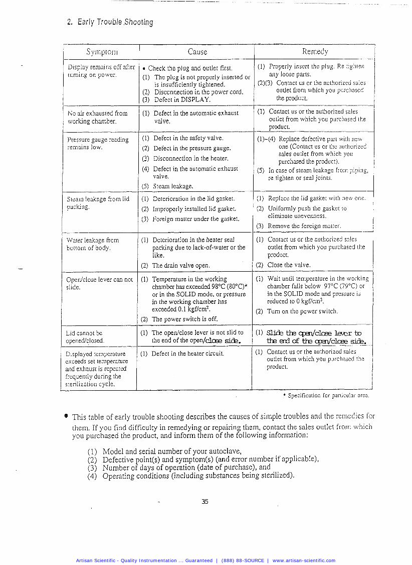
2 . E a r l y Trouble .Shooting
Symptom
Display remains off after turning on power.
No air exhausted from working chamber.
Pressure gauge reading remains low.
Steam leakage frorn lid packing.
Water leakage from bottom of body.
Opedclose lever can not slide.
Lid cannot be ~pened/closed.
Displayed temperature :xceeds set temperature md exhausr is repeared iequently during the ;terilization cycle.
Cause
Check the plug and outlet first. (1) The plug is not properly inserted or
is insufficiently tightened. (2) Disconnection in the power cord. (3) Defect in DISPLAY.
(1) Defect in the automatic exhaust valve.
(1) Defect in the safety valve.
(2) Defect in the pressure gauge.
(3) Disconnection in the heater.
(4) Defect in the automatic exhaust valve.
( 5 ) S t e m leakage.
(1) Deterioration in the lid gasket.
(2) Improperly installed lid gasket.
(3) Foreign matter under the gasket.
(1) Deterioratiorl in the heater seal packing due to lack-of-water or the like.
(2) The drain valve open.
(1) Temperature in the working chamber has exceeded 98°C (80°C)* or in the SOLID mode, or pressure in the working chamber has exceeded 0.1 kgf/cm2.
(2) The power switch is off. ~ --
(I) The open/close lever is not slid to the end of the o p e n / c k e &.
(1) Defect in the heater circuit.
Remedy
(1) Properly insert the plug. Re t~ghren any loose parts.
(2)(3) Contact us or the authorized sales outlet from which you purchased the product.
(1) Contact us or the authorized sales outlet frorn which you purchased the uroduct.
(1)-(4) Replace defective part wilh new one (Contact us or the authorized sales outlet from which you purchased the product).
(5) In case of s t e m leakage from piping, re tighten or seal joints.
(1) Replace the lid gasket with rlew one.
(2) Uniformly push the gasket to eliminate unevenness.
(3) Remove the foreign matter.
(1) Contact us or the authorized sales outlet from which you purchased the product.
(2) Close the valve.
(1) Wait until temperature in the working chamber falls below 97°C (79°C) or in the SOLID mode and pressure is reduced to 0 kgf/cm2.
(2) Turn on the power switch.
(1) Sli&tk&closelaerto tkcrddkqE?l /C lce2&.
(1) Contact us or the authorized sales outlet frorn which you purchased the product.
.* Specification for par[icular area .
This table of early trouble shooting describes the causes of simple troubles and the rernedies for them. If you find difficulty in remedying or repairing them, contact the sales outlet frorn which you purchased the product, and inform them of the following information:
(1) Model and serial number of your autoclave, (2) Defective point(s) and symptom(s) (and error number if applicable), (3) Number of days of operation (date of purchase), and (4) Operating conditions (including substances being sterilized).
Artisan Scientific - Quality Instrumentation ... Guaranteed | (888) 88-SOURCE | www.artisan-scientific.com
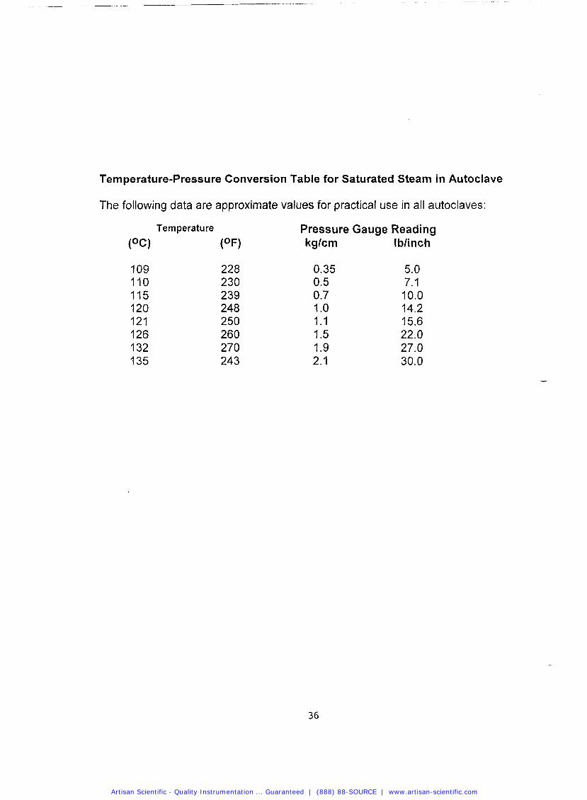
Temperature-Pressure Conversion Table for Saturated Steam in Autoclave
The following data are approximate values for practical use in all autoclaves:
Temperature Pressure Gauge Reading
(OC) (OF) kglcm lblinch
Artisan Scientific - Quality Instrumentation ... Guaranteed | (888) 88-SOURCE | www.artisan-scientific.com
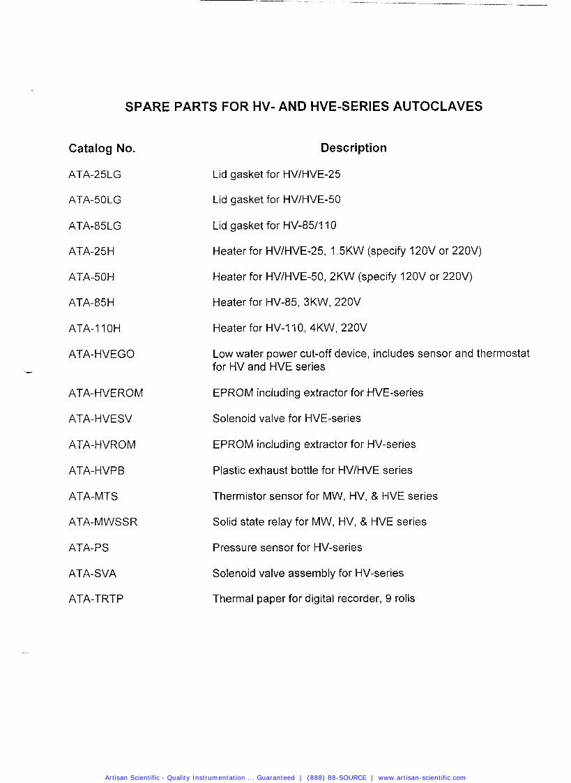
SPARE PARTS FOR HV- AND HVE-SERIES AUTOCLAVES
Catalog No.
ATA-25LG
ATA-50LG
ATA-85LG
ATA-25H
ATA-50H
ATA-85H
ATA-11 OH
ATA-HVEGO -
ATA-HVEROM
ATA-HVESV
ATA-HVROM
ATA-HVPB
ATA-MTS
ATA-MWSSR
ATA- P S
ATA-SVA
ATA-TRTP
Description
Lid gasket for HVIHVE-25
Lid gasket for HVIHVE-50
Lid gasket for HV-851110
Heater for HVIHVE-25, 1.5KW (specify 120V or 220V)
Heater for HVIHVE-50, 2KW (specify 120V or 220V)
Heater for HV-85, 3KW, 220V
Heater for HV-110, 4KW, 220V
Low water power cut-off device, includes sensor and thermostat for HV and HVE series
EPROM including extractor for HVE-series
Solenoid valve for HVE-series
EPROM including extractor for HV-series
Plastic exhaust bottle for HVIHVE series
Thermistor sensor for MW, HV, & HVE series
Solid state relay for MW, HV, & HVE series
Pressure sensor for HV-series
Solenoid valve assembly for HV-series
Thermal paper for digital recorder, 9 rolls
Artisan Scientific - Quality Instrumentation ... Guaranteed | (888) 88-SOURCE | www.artisan-scientific.com

Artisan Scientific - Quality Instrumentation ... Guaranteed | (888) 88-SOURCE | www.artisan-scientific.com

Looking for more information?Visit us on the web at http://www.artisan-scientific.com for more information:• Price Quotations • Drivers· Technical Specifications. Manuals and Documentation
Artisan Scientific is You~ Source for: Quality New and Certified-Used/Pre:-awned ECJuiflment• Tens of Thousands of In-Stock Items• Hundreds of Manufacturers Supported
• Fast Shipping and DelIve1y• Leasing / Monthly Rentals
• Equipment Demos• Consignment
Service Center RepairsExperienced Engineers and Technicians on staff in ourState-of-the-art Full-Service In-House Service Center Facility
InstraView Remote InspectionRemotely inspect equipment before purchasing with ourInnovative InstraView-website at http://www.instraview.com
We bUy used equipment! We also offer credit for Buy-Backs and Trade-InsSell your excess. underutilized. and idle used equipment. Contact one of our Customer Service Representatives todayl
Talk to a live person: 88EM38-S0URCE fB88-887-68721 I Contact us by email: [email protected] I Visit our website: http://www.artisan-scientific.com