Embed Size (px)
Citation preview

AS250
Ref.: DIV.SP.00151.DP.T.ASTR Issue: 1 Rev: 00
Date: 24/10/2011 Page 1 of 69
Document Autogenerated from DOORS Module : /DIVAS-AS250/Level 4/4.8 S-Band Transponder RS/AS250_S_Band_Transpondeur_ RS
AS250 Generic ---------------------
AS250 Low Cost S-BAND Transponder requirement specification
CI CODE: 439 DRL Refs :
Name and Function Date Signature
Prepared by E. COUTY
AS250 RF Engineer
Checked by: H.MARCILLE
AS250 Avionics Technical Synthesis
Approved by:
Serge CAZALS
AS250 Avionics Product Assurance Manager R. ROQUES
DHS and TTC MPC Manager
Authorised by: Ange DEFENDINI
AS250 Avionics Project Manager
Application Authorised by:
C. LEMERCIER
Head of Astrium EOS Satellite Product Definition & Implementation.
EADS ASTRIUM CONFIDENTIAL

AS250
Ref.: DIV.SP.00151.DP.T.ASTR Issue: 1 Rev: 00
Date: 24/10/2011 Page 2 of 69
The copyright in this document is the property of EADS ASTRIUM SAS and the contents may not be reproduced or revealed to third parties without prior permission of that company in writing. © EADS Astrium
EADS ASTRIUM CONFIDENTIAL
INTENTIONALLY BLANK

AS250
Ref.: DIV.SP.00151.DP.T.ASTR Issue: 1 Rev: 00
Date: 24/10/2011 Page 3 of 69
The copyright in this document is the property of EADS ASTRIUM SAS and the contents may not be reproduced or revealed to third parties without prior permission of that company in writing. © EADS Astrium
EADS ASTRIUM CONFIDENTIAL
CONTENTS
1. INTRODUCTION AND SCOPE ..................................................................................................................7 1.1 Introduction..........................................................................................................................................7 1.2 Scope ..................................................................................................................................................7 1.3 Summary Description...........................................................................................................................8
2. APPLICABLE DOCUMENTS....................................................................................................................12
3. UNIT/EQUIPMENT FUNCTIONAL AND PERFORMANCE REQUIREMENTS.........................................13 3.1 Unit/Equipment Definition ..................................................................................................................13 3.2 Transponder Performance Requirements ..........................................................................................13
3.2.1 Receiver Performance Requirements ......................................................................................13 3.2.2 Transmitter Performances Requirements ................................................................................22 3.2.3 General Transponder Requirements........................................................................................30
3.3 Ranging Performance Requirements.................................................................................................31 3.3.1 Ranging Input Signals..............................................................................................................31 3.3.2 Ranging Tone Frequency ........................................................................................................31 3.3.3 Ranging Modulation Indices.....................................................................................................32 3.3.4 Ranging Channel Group Delay Stability...................................................................................32 3.3.5 Ranging Video AGC.................................................................................................................32 3.3.6 Ranging Demodulation Performances .....................................................................................32 3.3.7 Ranging Signal Polarity............................................................................................................33 3.3.8 Ranging ON/OFF Switching.....................................................................................................33 3.3.9 Stability Requirement for Doppler Tracking..............................................................................33
3.4 S-Band TT&C Command & Housekeeping ........................................................................................33 3.4.1 Receiver Housekeeping...........................................................................................................33 3.4.2 Transmitter Housekeeping.......................................................................................................34 3.4.3 List of High Power Commands.................................................................................................36 3.4.4 List of Housekeeping Signals...................................................................................................36
4. UNIT/EQUIPMENT SPECIFIC DESIGN AND INTERFACE REQUIREMENTS ........................................38 4.1 Lifetime ..............................................................................................................................................38 4.2 Mechanical Requirements .................................................................................................................38
4.2.1 Mass ........................................................................................................................................38 4.2.2 Centre of Gravity......................................................................................................................38 4.2.3 Envelope..................................................................................................................................38
4.3 Electrical Requirements .....................................................................................................................38 4.3.1 Power Consumption / Dissipation ............................................................................................38 4.3.2 Power Interfaces......................................................................................................................38 4.3.3 Housekeeping Command & Telemetry Interfaces....................................................................39 4.3.4 S-Band Digital TC Channel Interface .......................................................................................39 4.3.5 S-Band Digital TM Channel Interface.......................................................................................40 4.3.6 Software data interfaces ..........................................................................................................40
4.4 Magnetic Moment ..............................................................................................................................40 4.5 Unit/Equipment Reliability Requirement.............................................................................................40 4.6 Doppler Frequency ............................................................................................................................42
5. GENERAL DESIGN AND INTERFACE REQUIREMENTS.......................................................................43
6. PRODUCT ASSURANCE REQUIREMENTS ...........................................................................................44

AS250
Ref.: DIV.SP.00151.DP.T.ASTR Issue: 1 Rev: 00
Date: 24/10/2011 Page 4 of 69
The copyright in this document is the property of EADS ASTRIUM SAS and the contents may not be reproduced or revealed to third parties without prior permission of that company in writing. © EADS Astrium
EADS ASTRIUM CONFIDENTIAL
7. VERIFICATION REQUIREMENTS ...........................................................................................................45 7.1 Required Unit/Equipment Level Tests................................................................................................45
7.1.1 Functional/Performance Tests .................................................................................................45 7.1.2 EMC Requirements..................................................................................................................45 7.1.3 Mechanical Tests.....................................................................................................................46 7.1.4 Thermal design environment....................................................................................................46 7.1.5 Radiation Requirements ..........................................................................................................46 7.1.6 Specific requirements ..............................................................................................................47
8. ANNEX I: GDIR APPLICABILITY MATRIX ........................................................................................48
9. ABBREVIATIONS LIST ............................................................................................................................66
TABLES None
FIGURES Figure 1.3-1: AS250 S-Band Transponder Block Diagram..............................................................................9 Figure 1.3-2: AS250 S-Band TT&C Block Diagram.......................................................................................10 Figure 3.2-1: Receiver Rejection Mask ........................................................................................................17 Figure 3.2-2 : conducted susceptibility at antenna terminal...........................................................................18 Figure 3.2-3: Data Valid Timing ....................................................................................................................19 Figure 3.2-4: Theoretical BER ......................................................................................................................21 Figure 3.2-5:QPSK mapping.........................................................................................................................23 Figure 3.2-6:mapping allocation....................................................................................................................23

AS250
Ref.: DIV.SP.00151.DP.T.ASTR Issue: 1 Rev: 00
Date: 24/10/2011 Page 5 of 69
The copyright in this document is the property of EADS ASTRIUM SAS and the contents may not be reproduced or revealed to third parties without prior permission of that company in writing. © EADS Astrium
EADS ASTRIUM CONFIDENTIAL
INTENTIONALLY BLANK

AS250
Ref.: DIV.SP.00151.DP.T.ASTR Issue: 1 Rev: 00
Date: 24/10/2011 Page 6 of 69
The copyright in this document is the property of EADS ASTRIUM SAS and the contents may not be reproduced or revealed to third parties without prior permission of that company in writing. © EADS Astrium
EADS ASTRIUM CONFIDENTIAL
SUMMARY

AS250
Ref.: DIV.SP.00151.DP.T.ASTR Issue: 1 Rev: 00
Date: 24/10/2011 Page 7 of 69
The copyright in this document is the property of EADS ASTRIUM SAS and the contents may not be reproduced or revealed to third parties without prior permission of that company in writing. © EADS Astrium
EADS ASTRIUM CONFIDENTIAL
1. INTRODUCTION AND SCOPE
1.1 Introduction
This document establishes the design, performance, interface and verification requirements of a low cost S Band Transponder for the Tracking, Telemetry and Command Subsystem on board the AS250 avionics.
Depending on the program, one out of the three following uplink modulations will be selected:
- Option 1: uplink direct BPSK modulation (Note 1),
- Option 2: uplink direct QPSK modulation (Note 1),
- Option 3: uplink PCM/SP-L/PM modulation.
One out of the five following downlink modulations will be selected (Note 2):
- Option A: downlink direct BPSK modulation,
- Option B: downlink direct QPSK modulation,
- Option C: downlink direct OQPSK modulation
- Option D: downlink PCM/PSK/PM modulation,
- Option E: downlink PCM/SP-L/PM modulation.
A project specific specification including all the specific requirements (selected options, frequency, output power, bit rate etc....) will be issued at the beginning of each program.The uplink modulation selection and the downlink modulation selection for a given program will be defined in the program-specific S-band transponder delta-specification.
All the requirements which are program dependant are identified by TBS (To be Specified) in the following technical specification.
Note: For specific project two different modulations can be selected for the downlink telemetry if two different bit rates are required. In such a case the uplink modulation is always the same but the downlink modulation can be selected between two different modulations by dedicated telecommand from ground.
For this option two specific commands (to set the high bit rate on or off which is the main requirement) and their corresponding status are defined.
1.2 Scope
The document in hand comprises the contractually relevant technical requirements and constraints for the AS250 S Band Transponder. This includes:
• the performance as well as design and interface requirements of subject hardware
• the testing and verification requirements.
AS250
Ref.: DIV.SP.00151.DP.T.ASTR Issue: 1 Rev: 00
Date: 24/10/2011 Page 8 of 69
The copyright in this document is the property of EADS ASTRIUM SAS and the contents may not be reproduced or revealed to third parties without prior permission of that company in writing. © EADS Astrium
EADS ASTRIUM CONFIDENTIAL
Requirements within this document are shown in an italic font. Each requirement is preceded by a summary line that contains the following fields, delimited by "/".
• Doors Requirement Number
• Created From
• Intended Verification Method
The Doors Requirement Number has the form SBTA-xxx where xxx is a unique number assigned consecutively.
The Created From field shows the parent requirement or "Created" if the requirement is created at this level.
The Intended Verification Method codes are as follows:
• R - Review
• A - Analysis
• I - Inspection
• T - Test
The requirement text follows the summary line. If tables are considered as part of requirement they are referenced clearly in the text and inserted after and separated from the requirement and are managed as free text attached to the identifier requirement.
All document elements, which are not presented in the format explained above are not requirements and will not be verified or tracked.
1.3 Summary Description
The here specified transponder is part of the AS250 S-band TT&C subsystem which is the spacecraft Tracking, Telemetry & Command subsystem operating in S-band.
This subsystem acts as the interface between the satellite and dedicated ground stations, and represents one essential part of the S/C command and control capability by ground.
The S-band TT&C subsystem consists of all elements for RF reception, demodulation, modulation and transmission. The fundamental functions are:
· to receive and demodulate S-band uplink signals (note 1) for telecommand purposes,
· to transmit S-band downlink telemetry data signals,
· and as an option to provide a ranging channel with or without coherent mode of operation to allow to provide range and range-rate (relative Doppler shift) measurements.
The S Band Transponder supports the TT&C in order to guarantee communication with ground during all mission phases.

AS250
Ref.: DIV.SP.00151.DP.T.ASTR Issue: 1 Rev: 00
Date: 24/10/2011 Page 9 of 69
The copyright in this document is the property of EADS ASTRIUM SAS and the contents may not be reproduced or revealed to third parties without prior permission of that company in writing. © EADS Astrium
EADS ASTRIUM CONFIDENTIAL
This present specification is the transponder only specification and is not the TTC subsystem specification.
note 1: At transponder level, there is no data processing for the TC.
The general block diagram of the on-board TT&C S-band subsystem based on the current S-band transponder is schematically depicted in the Figure below.
Power_busON/OFF TC
ON/OFF TCPower_bus
Transponder 1
Transponder 2
Figure 1.3-1: AS250 S-Band Transponder Block Diagram
Note: The received TC shall be output via the TC output port and this output shall be cross-strapped and send simultaneously at two numerical inputs for decoding. There are two inputs for redundancy reasons. The cross-strapping shall be done at harness level (option a1) or at receiver output level (option a2) i.e. it shall be possible for the receiver to output the TC received through two identical TC outputs (1 nominal output and 1 redundant output).
The TM interface is nominally made of two signals (DATA + CLK) but it shall be possible to receive also the BPSK frequency subcarrier.
And the transponder block diagram is given on the following diagram :

AS250
Ref.: DIV.SP.00151.DP.T.ASTR Issue: 1 Rev: 00
Date: 24/10/2011 Page 10 of 69
The copyright in this document is the property of EADS ASTRIUM SAS and the contents may not be reproduced or revealed to third parties without prior permission of that company in writing. © EADS Astrium
EADS ASTRIUM CONFIDENTIAL
diplexer
DC/DC Converter
DC/DC Converter
Coherent Ranging channel
Power supply
RF link
2025-2120 MHz
2200-2300 MHz
TM interface nomBPSK modulator orQPSK modulator orOQPSK modulator orPCM/BPSK/PM modulator or PCM/SPL/PM modulator
1 or 2 modulators(2 if dual bit rate)} 2 or 3
BPSK modulator orQPSK modulator or
PCM/BPSK/PM modulator or PCM/SPL/PM modulator
44
Rx LS +Data + CLK + Squelch
Data + CLK + Squelch+ Rx LS
Note: Rx LS Receiver Lock Status
TM interface red
2 or 3
CMD and HousekeepingPower supply
ConvolutionalEncoder
Figure 1.3-2: AS250 S-Band TT&C Block Diagram
Depending on which modulator option is selected, the TM interface input data will be provided as one of the following sets of signals :
- either NRZ data, clock (and sub-carrier clock),
- or a sub-carrier modulated by BPSK and clock signal (the frequency of which being equal to twice the pre-modulation frequency) in case BPSK modulation is done in the OBC,
- or I+Q+Clock signals for QPSK modulation by the transponder.
For TC output port, only DATA, CLK and SQUELCH are used to decode the numerical TC, the carrier lock status (Rx LS) is not directly used to decode the received TC.

AS250
Ref.: DIV.SP.00151.DP.T.ASTR Issue: 1 Rev: 00
Date: 24/10/2011 Page 11 of 69
The copyright in this document is the property of EADS ASTRIUM SAS and the contents may not be reproduced or revealed to third parties without prior permission of that company in writing. © EADS Astrium
EADS ASTRIUM CONFIDENTIAL
Rx
Output_1
OBC_A
OBC_B
Input_n
Input_r
Cross-strapped at harness level
OBC_A
OBC_B
Input_n
Input_r
RxOutput_n
Output_r
Cross-strapped at receiver output level
Option a1 Option a2

AS250
Ref.: DIV.SP.00151.DP.T.ASTR Issue: 1 Rev: 00
Date: 24/10/2011 Page 12 of 69
The copyright in this document is the property of EADS ASTRIUM SAS and the contents may not be reproduced or revealed to third parties without prior permission of that company in writing. © EADS Astrium
EADS ASTRIUM CONFIDENTIAL
2. APPLICABLE DOCUMENTS
The following documents are applicable documents to this specification. Only those parts of them are applicable for the contractors product design, test and manufacturing which are distinctly made transparent by references within this specification.
[AD 01] DIV.SP.00027.T.ASTR AS250 General Design and Interface Requirements.
[AD 02] N/A
[AD 03] ECSS-E-ST-50-01C Space engineering - Space data links - Telemetry Synchronization and Channel Coding
[AD 04] ECSS-E-ST-50-02C Ranging and Doppler Tracking
[AD 05] ECSS-E-ST-50-05C Radio Frequency and Modulation Standard.
[AD 06] ECSS-E-ST-50-03C Telemetry transfer frame protocol
[AD 07] ECSS-E-ST-50-04C Telecommand protocols, synchronization and channel coding
AS250
Ref.: DIV.SP.00151.DP.T.ASTR Issue: 1 Rev: 00
Date: 24/10/2011 Page 13 of 69
The copyright in this document is the property of EADS ASTRIUM SAS and the contents may not be reproduced or revealed to third parties without prior permission of that company in writing. © EADS Astrium
EADS ASTRIUM CONFIDENTIAL
3. UNIT/EQUIPMENT FUNCTIONAL AND PERFORMANCE REQUIREMENTS
3.1 Unit/Equipment Definition
SBTA-30 / R
The S Band Transponder shall be self contained except antennas and cables, it shall comprise all elements for RF reception, demodulation, modulation and transmission excluding the antennas, coaxial cables and the 3 dB coupler.
SBTA-31 / R
The principal functions of the S Band Transponder shall be:
· to receive and demodulate S-band uplink signals for telecommand purposes,
· to convolutionally code, modulate and transmit S-band downlink telemetry data signals,
· to provide as mandatory option a ranging channel to allow range and range-rate (relative Doppler shift) measurements. It shall be possible to not select this option.
· to provide as mandatory option a coherent mode of operation to allow range-rate (relative Doppler shift) measurements. It shall be possible to not select this option.
SBTA-32 / R
The S-band transponder shall comprise the following:
. a receiver, a transmitter and a diplexer.
. appropriate RF harness and any necessary feed through connectors interconnecting the individual elements of the transponder.
SBTA-33 / R
All the requirements and performances specified within this specification shall be applicable during the whole mission i.e. in worst case End Of life conditions.
3.2 Transponder Performance Requirements
3.2.1 Receiver Performance Requirements
3.2.1.1 Demodulation Characteristics
SBTA-416 / T,R
The uplink modulation type shall be :
- Binary Phase Shift Keying (BPSK) of the uplink carrier (TC option 1) or,
- Quadrature Phase Shift Keying (QPSK) of the uplink carrier (TC option 2) or
- Pulse Code Modulated, Split Phase Level, phase modulation(PCM/SP-L/PM) of the uplink carrier (TC option 3).

AS250
Ref.: DIV.SP.00151.DP.T.ASTR Issue: 1 Rev: 00
Date: 24/10/2011 Page 14 of 69
The copyright in this document is the property of EADS ASTRIUM SAS and the contents may not be reproduced or revealed to third parties without prior permission of that company in writing. © EADS Astrium
EADS ASTRIUM CONFIDENTIAL
In case of PM modulation selected (option 3) , the command PM modulation index shall be within 0,2 to 1,0 rad-peak with an accuracy of ± 5% with no simultaneous ranging (According to AD5, §6.1.6).
SBTA-417 / R
The nominal S-band telecommand bit rate shall be between 16 kbps and 64 Kbps in order to comply with the on-board computer TC bit rate performances supported.
SBTA-418 / R
Whatever is the modulation, BPSK (option 1), QPSK (option 2) or PCM/SP-L/PM (option 3), the receiver shall demodulate the telecommand data and shall output either to two buffered digital outputs of the telecommand, or to a signal buffered digital outputs design specially to allow reliable cross-strapping in the harness.
Each output is made of a telecommand data line, a clock data line and a squelch data signal. These 3 signals have the electrical interfaces compliant to AD1, SBDL definition, §3.5.4.2.
(The additional RF_carrier_lock signal is output in the same SBDL electrical format).
3.2.1.2 Rest Frequency
SBTA-41 / R
The rest frequency of the receiver shall be defined as the uplink frequency which leads to a zero beat frequency at the output of the phase detector (SPE) of the narrow band PLL when the receiver is locked on the uplink carrier measured with 1 second integration time.
The rest frequency is calculated as (221 / 240) x FTx. This method is used to calculate the receiver frequency during validation and test.
For Option 3 of the uplink modulation, the L.O. is implemented by a narrow band PLL, in which a VCO is driven by a crystal oscillator. The error signal of this narrow band loop drives the VCO when the Rx is not locked on the uplink carrier.
For Option 1 and Option 2 of the uplink modulation the receiver design is such that RF stages are able to recover the carrier in compatibility with the acquisition process and assuming a sufficient bit rate to ensure this compatibility. The same narrow band PLL are provided as for the 2 previous options.
SBTA-42 / R
The receiver rest frequency shall be TBS ( at ±2 KHz) at the time of manufacture in the range 2025 MHz - 2120 MHz and shall be defined at the kick-off of the project.
SBTA-44 / T
The frequency stability of the rest frequency shall have the following characteristics:
- the initial setting shall be within ±10 kHz of the assigned value, at a temperature 22°C ±3°C,
- the Ageing contribution shall be ±15 kHz,
- the Temperature contribution shall be ±15 kHz.

AS250
Ref.: DIV.SP.00151.DP.T.ASTR Issue: 1 Rev: 00
Date: 24/10/2011 Page 15 of 69
The copyright in this document is the property of EADS ASTRIUM SAS and the contents may not be reproduced or revealed to third parties without prior permission of that company in writing. © EADS Astrium
EADS ASTRIUM CONFIDENTIAL
3.2.1.3 PLL Equivalent Phase-Lock Noise Bandwidth
SBTA-46 / T
The double-sided phase-lock loop noise bandwidth (2BL) shall be 800 Hz ± 20% at carrier acquisition threshold.
3.2.1.4 Noise Figure
SBTA-48 / T
The receiver noise figure shall be lower than 2,5 dB at receiver level (i.e. 4,5 dB including the diplexer), at the Carrier Acquisition Threshold.
3.2.1.5 Carrier Acquisition and Tracking
The carrier acquisition threshold is the input RF power level at which the receiver gets locked with a probability better than 99% after a frequency sweep as described in STBA-52.
SBTA-419 / T
The worst case carrier acquisition threshold of the S Band Receiver shall be in the range -118dBm ;-128 dBm at the diplexer input interface, with a source noise temperature of 300 K, and using a non modulated carrier.
For RF level received lower than 7 dB under the lock threshold, the lock probability shall be lower than 1%.
=> with a -118 dBm threshold, the no lock threshold shall be -125 dBm and
=> with a -128 dBm threshold, the no lock threshold shall be -135 dBm.
SBTA-52 / T,A
The receiver shall acquire a non modulated uplink carrier swept by ±60 kHz through the rest frequency at any rate up to 32 kHz/s maximum for all carrier levels between carrier acquisition threshold and -50 dBm with a probability better than 99%, after 3 frequency transitions.
SBTA-53 / T
The receiver shall remain locked while the uplink carrier is swept by ±140 KHz around the nominal frequency at any rate up to 50 kHz/sec maximum for a residual carrier level from threshold to -50 dBm.

AS250
Ref.: DIV.SP.00151.DP.T.ASTR Issue: 1 Rev: 00
Date: 24/10/2011 Page 16 of 69
The copyright in this document is the property of EADS ASTRIUM SAS and the contents may not be reproduced or revealed to third parties without prior permission of that company in writing. © EADS Astrium
EADS ASTRIUM CONFIDENTIAL
3.2.1.6 RF Input Limits
SBTA-55 / T,A
The receiver shall withstand an input power of 0 dBm in the receive frequency 2025-2120 MHz range for 60 minutes without permanent damage.
The test duration could be reduced to 5 minutes if the 60 minutes of withstanding are proven by analysis.
3.2.1.7 Receiver Spurious Response
SBTA-57 / T
In the presence of an interference signal defined in the list of requirement below, at the transponder input interface, the following requirements shall be fulfilled:
· When the receiver is unlocked, it shall be free from all indications of false lock, frequency pushing, self lock or instability, independent of whether the associated transmitter is powered on or off.
· When the receiver is locked, it shall be free from all indications of instability, independent of whether the associated transmitter is powered on or off.
SBTA-428 / T
The Transponder Assembly shall keep all its performances characteristics when Narrowband (NB) disturbances according to the table below are injected into the diplexer input port with Fo being the nominal receiver rest frequency and level interpolation to be performed between the frequency steps.
13 kHz to Fo-150MHz 0 dBm
Fo-150MHz to Fo-80MHz decreasing from 0 dBm to -50 dBm
Fo-80MHz to Fo-20MHz decreasing from -50 dBm to -90 dBm
Fo-20MHz to Fo-4MHz decreasing from -90 dBm to -140 dBm
Fo +/- 4 MHz -140 dBm
Fo+4MHz to Fo+20MHz increasing from -140 dBm to -90 dBm
Fo+20MHz to Fo+80MHz increasing from -90 dBm to -50 dBm
Fo+80MHz to Fo+150MHz increasing from -50 dBm to 0 dBm
Fo+150MHz to 2.2GHz 0 dBm
2.2 GHZ to 2.3 GHz +37 dBm or the maximum RF output power defined in SBTA-422
-6dB whichever is highest value.
(RF Autocompatibility with TM downlink)

AS250
Ref.: DIV.SP.00151.DP.T.ASTR Issue: 1 Rev: 00
Date: 24/10/2011 Page 17 of 69
The copyright in this document is the property of EADS ASTRIUM SAS and the contents may not be reproduced or revealed to third parties without prior permission of that company in writing. © EADS Astrium
EADS ASTRIUM CONFIDENTIAL
2.3 GHz to 8.4 GHz 0 dBm
(RF Autocompatibility with X-band payload telemetry)
8.0 GHz to 8.5 GHz +10 dBm
8.5 GHz to 22 GHz 0 dBm
Here is the corresponding diagram :
+10 dBm
+ 0 dBm
-10 dBm
-50 dBm
-90 dBm
-100 dBm
+20 dBm
+40 dBm
+30 dBm+35 dBm
F0 + 150 MHz
2.2 2.3
8.0 8.5 GHz
22 GHz
-140 dBm
F0 + 80 MHz
F0 + 20 MHz
F0 + 4 MHzF0 - 4 MHz
F0 - 20 MHz
F0 - 80 MHz
F0 - 150 MHz F0
+35 dBm
+10 dBm
GHz GHz
Figure 3.2-1: Receiver Rejection Mask
3.2.1.8 RF compatibility during launch (via conducted susceptibility test)
SBTA-60 / T,A
During the launch phase, the Transponder assembly shall not be damaged by the following disturbances injected at the diplexer input without time limitation:
• In the frequency range [10 kHz - 100 MHz], sine wave signal with a maximum level of -30 dBm,
• In the frequency range [100 MHz - 10 GHz], sine wave signal with the maximum levels defined in the following figure.
Remark:

AS250
Ref.: DIV.SP.00151.DP.T.ASTR Issue: 1 Rev: 00
Date: 24/10/2011 Page 18 of 69
The copyright in this document is the property of EADS ASTRIUM SAS and the contents may not be reproduced or revealed to third parties without prior permission of that company in writing. © EADS Astrium
EADS ASTRIUM CONFIDENTIAL
During the injection of the sine wave signal of -30 dBm in the RX frequency range F0 +/- 80 MHz, full performances are not required but the receiver shall not be overstressed during the CS test and shall recover full performances after the injection in the RX band.
Conducted Susceptibility at antenna terminal
5900
MH
z; -7
dB
m
5400
MH
z; -7
dBm
3500
MH
z; -1
dBm
2750
MH
z; -1
dBm
2290
MH
z; 5
dBm
2200
MH
z; 5
dBm
1700
MH
z; 6
dB
m
1250
MH
z; 6
dBm
970
MH
z; 8
dB
m
650
MH
z; -1
dBm
630
MH
z; -1
dBm
250
MH
z; 1
dB
m
190
MH
z; 1
dB
m14
4.40
MH
z; -1
7 dB
m
140.
40 M
Hz;
-17
dBm
-40
-30
-20
-10
0
10
100 100001000 MHz
dBm
Figure 3.2-2 : conducted susceptibility at antenna terminal
3.2.1.9 Receiver Back Radiation
SBTA-63 / T
The receiver shall maintain its nominal performances when sharing the same signal source with another identical receiver in working mode, the two transponders operating with 6dB of inserted isolation and with any phase shift at their inputs.
3.2.1.10 Receiver RF input
SBTA-65 / T
The RX RF input impedance shall be of 50 ohm with a maximum VSWR of 1,3 for the input signal.
3.2.1.11 TC Demodulation Performances
3.2.1.11.1 Telecommand signal characteristics
SBTA-352 / T,A,R
For PM modulations, the carrier phase noise shall be better than 5° rms integrated between 10 Hz and 100 KHz.
AS250
Ref.: DIV.SP.00151.DP.T.ASTR Issue: 1 Rev: 00
Date: 24/10/2011 Page 19 of 69
The copyright in this document is the property of EADS ASTRIUM SAS and the contents may not be reproduced or revealed to third parties without prior permission of that company in writing. © EADS Astrium
EADS ASTRIUM CONFIDENTIAL
SBTA-353 / T,A,R
For PM modulation, the modulation linearity shall be better than 3%.
SBTA-354 / T,A,R
For PCM/BPSK/PM modulation the subcarrier shall be a sinus subcarrier with a frequency of 8 KHz or 16 KHz and a frequency stability better than ± 3.5 10-5 (all errors, including initial, setting and Doppler).
SBTA-360 /
The bit rate stability shall be ≤ ± 3.5 10-5 including all errors (initial, setting and Doppler).
3.2.1.11.2 Data Valid
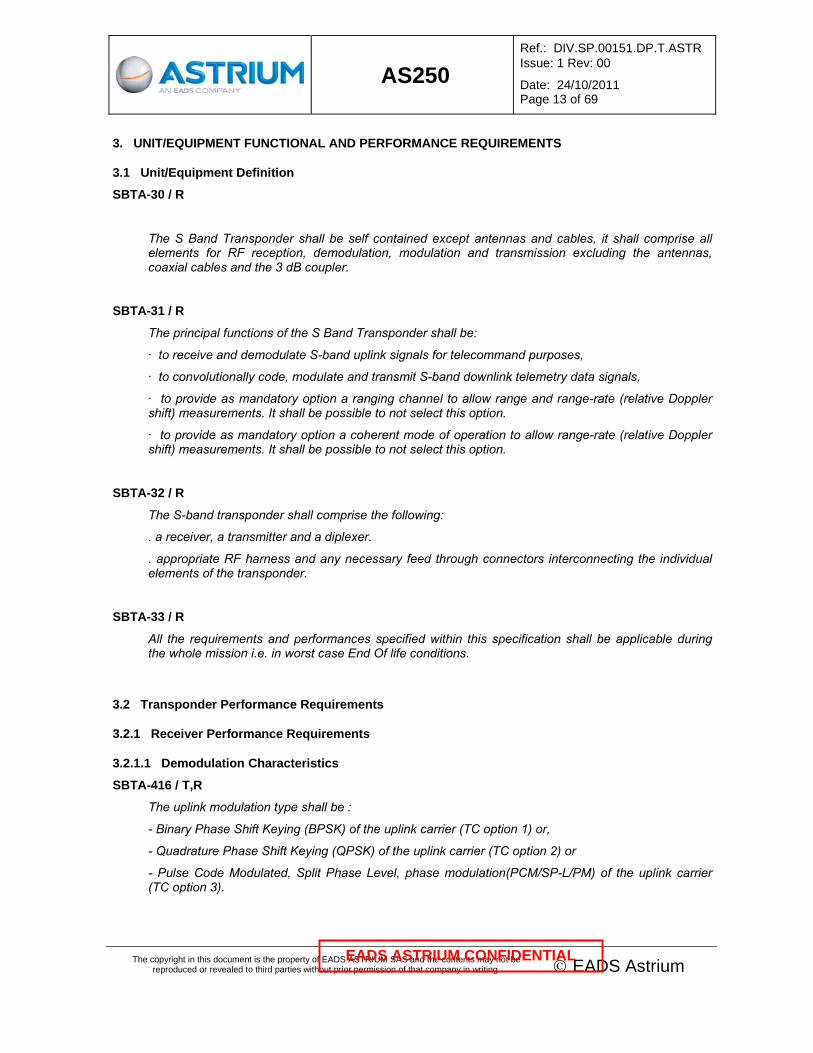
SBTA-69 / T
A data valid signal shall be generated in order to indicate that the output data stream quality is better than 9,6 dB Eb/N0 threshold (B.E.R. < 10-5).
The 'data valid' timing shall be as indicated in the figure below, where <T1 and T2 shall be less than the duration of 168 uplink bit periods for the specified uplink data rate TBC>.
Data Valid
Data preamble
T1 T2
Figure 3.2-3: Data Valid Timing
3.2.1.11.3 Command demodulation performances
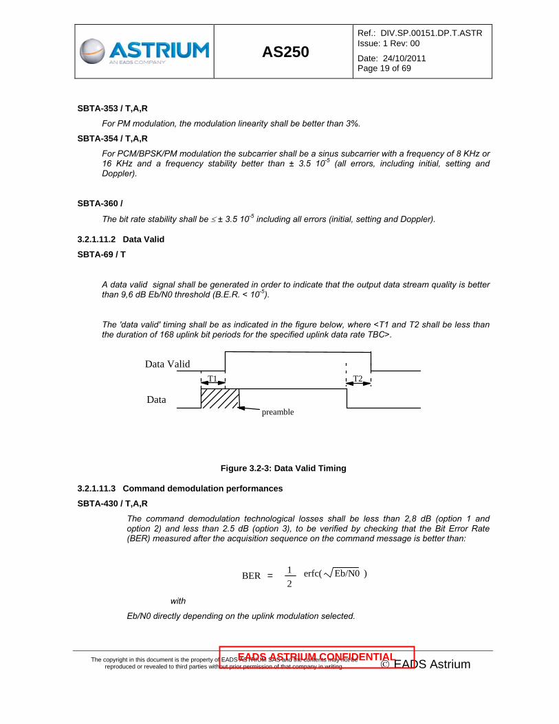
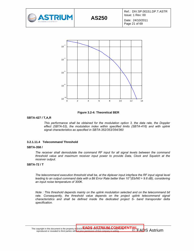
SBTA-430 / T,A,R
The command demodulation technological losses shall be less than 2,8 dB (option 1 and option 2) and less than 2.5 dB (option 3), to be verified by checking that the Bit Error Rate (BER) measured after the acquisition sequence on the command message is better than:
Eb/N0erfc(BER = 12
)
with
Eb/N0 directly depending on the uplink modulation selected.

AS250
Ref.: DIV.SP.00151.DP.T.ASTR Issue: 1 Rev: 00
Date: 24/10/2011 Page 20 of 69
The copyright in this document is the property of EADS ASTRIUM SAS and the contents may not be reproduced or revealed to third parties without prior permission of that company in writing. © EADS Astrium
EADS ASTRIUM CONFIDENTIAL
For Option 1 and option 2, uplink BPSK modulation or QPSK modulation, the Eb/N0 is given by the following formula :
dB 2.8 - (D) Log 10- Fb - 174.0 + Pe = N0Eb
For Option 3, the PCM/PSK/PM with subcarrier modulation the Eb/N0 is given by the following formula :
dB 2.5 - (D) Log 10- ))(J (2 Log 10 + Fb - 174.0 + Pe = N0Eb 2
1 θ
For Option 4, the PCM/SP-L/PM modulation without subcarrier and direct modulation of the carrier, the Eb/N0 is given by the following formula :
dB 2.5 - (D) Log 10- ))( Log 10 + Fb - 174.0 + Pe = N0Eb 2 θ(Sin
In all these equations, the following parameters are used:
Pe : Total transponder input power at diplexer input(dBm)
Fb : Specified noise figure (dB) (SBTA-48)
J1(θ) : 2nd order Bessel function
θ : Peak modulation angle
D : TC bit rate
2,8 dB : Maximum receiver demodulation technological losses (option 1 and 2)
2.5 dB : Maximum receiver demodulation technological losses (option 3 and 4)
And theoretical
Eb/N0erfc(BER = 12
)
illustrated in the following diagram.
AS250
Ref.: DIV.SP.00151.DP.T.ASTR Issue: 1 Rev: 00
Date: 24/10/2011 Page 21 of 69
The copyright in this document is the property of EADS ASTRIUM SAS and the contents may not be reproduced or revealed to third parties without prior permission of that company in writing. © EADS Astrium
EADS ASTRIUM CONFIDENTIAL
0 2 4 6 8 10 12 1410
-10
10-8
10-6
10-4
10-2
Figure 3.2-4: Theoretical BER
SBTA-427 / T,A,R
This performance shall be obtained for the modulation option 3, the data rate, the Doppler effect (SBTA-53), the modulation index within specified limits (SBTA-416) and with uplink signal characteristics as specified in SBTA-352/353/354/360
3.2.1.11.4 Telecommand Threshold
SBTA-358 /
The receiver shall demodulate the command RF input for all signal levels between the command threshold value and maximum receiver input power to provide Data, Clock and Squelch at the receiver output.
SBTA-72 / T
The telecommand execution threshold shall be, at the diplexer input interface the RF input signal level leading to an output command data with a Bit Error Rate better than 10-5(Eb/N0 > 9.6 dB), considering an input noise temperature of 300K.
Note : This threshold depends mainly on the uplink modulation selected and on the telecommand bit rate. Consequently, the threshold value depends on the project uplink telecommand signal characteristics and shall be defined inside the dedicated project S- band transponder delta specification.

AS250
Ref.: DIV.SP.00151.DP.T.ASTR Issue: 1 Rev: 00
Date: 24/10/2011 Page 22 of 69
The copyright in this document is the property of EADS ASTRIUM SAS and the contents may not be reproduced or revealed to third parties without prior permission of that company in writing. © EADS Astrium
EADS ASTRIUM CONFIDENTIAL
3.2.1.11.5 TC Timing
SBTA-420 / T
The receiver shall comply the uplink acquisition timing diagram defined in AD1, §3.5.4.13.1 with T1 ≤ 168 bits.
The lock carrier status output shall be generated as described on this timing diagram (§3.5.4.13.1 of [AD1]) when the transponder is locked on the RF carrier.
SBTA-75 / T
The Bit synchroniser within the Transponder shall not require a frequency sweep for subcarrier or bit lock acquisition, which shall be achieved using the preamble (idle sequence) transmitted before all uplink messages.
3.2.1.11.6 Bit Synchronisation
SBTA-77 / T
The demodulator shall not loose bit synchronisation, and the Data Valid shall remain in its valid state when the S-Band subassembly receives a telecommand according to the ESA Packet Telecommand Standard PSS-04-107, §5.2 (no scrambling) and with any given number of codeblocks, each consisting of seven octets of zeros (information field) and the referring error control field (seven “1” and a final “0” as check bits), i.e.:0000 0000 0000 0000 0000 0000 0000 0000 0000 0000 0000 0000 0000 0000 1111 1110. The generated check bits provides the minimum number of transitions, i.e. 2 transitions in a field of 64 bits.
3.2.1.11.7 Receiver Locking sequences
SBTA-421 / A,R
The receiver shall support without degradation (for a 7 years lifetime mission) :
-5000 locking cycles on ground during spacecraft integration and
-38000 cycles in orbit.
A locking cycle is defined by the consecutive states of the receiver: unlocked, locked (even on a pure carrier) and unlocked.
3.2.2 Transmitter Performances Requirements
3.2.2.1 Modulation Inputs
SBTA-84 / R
Each transmitter shall accept one external telemetry modulation input signal from the Data Handling subsystem.

AS250
Ref.: DIV.SP.00151.DP.T.ASTR Issue: 1 Rev: 00
Date: 24/10/2011 Page 23 of 69
The copyright in this document is the property of EADS ASTRIUM SAS and the contents may not be reproduced or revealed to third parties without prior permission of that company in writing. © EADS Astrium
EADS ASTRIUM CONFIDENTIAL
3.2.2.2 Convolutional Coding
SBTA-393 / R
Each Transmitter shall provide internally a convolutional (or viterbi) encoder. It shall be possible to activate or bypass/disable this encoder as a mission-dependent configuration option. In case of QPSK modulation, the mapping between Viterbi output bits S1, S2 and QPSK phases shall be deterministic (constant and predictable), preferably as described hereafter (TBC by supplier):
Figure 3.2-5:QPSK mapping
S1 S2 0 1 0 45° 315° 1 135° 225°
Figure 3.2-6:mapping allocation
3.2.2.3 Modulation Scheme
SBTA-86 / T
The transmitter frequency shall be selectable within 2200-2290 MHz at the time of manufacture with the following rules:
-when coherent mode is supported by the transponder, the frequency shall be exactly 240/221 of the reception frequency,
-when coherent mode is not supported by the transponder, the frequency shall be within the previous range.
In both cases, the frequency value shall be within ± 44 KHz of the frequency limits i.e. higher than 2200 MHz + 44 KHz and lower than 2290 MHz - 44 KHz.
AS250
Ref.: DIV.SP.00151.DP.T.ASTR Issue: 1 Rev: 00
Date: 24/10/2011 Page 24 of 69
The copyright in this document is the property of EADS ASTRIUM SAS and the contents may not be reproduced or revealed to third parties without prior permission of that company in writing. © EADS Astrium
EADS ASTRIUM CONFIDENTIAL
Note: The range 2290 MHz to 2300 MHz is reserved for DSN application.
SBTA-87 / T
The nominal transmit carrier frequency for the corresponding spacecraft shall be defined upon customer responsibility at the beginning of the project.
SBTA-88 / T
The transmitter carrier frequency shall be set within ± 5 ppm of the nominal transmit carrier frequency, at a temperature of 22°C ± 3°C.
SBTA-89 / T
The transmitter carrier frequency shall not vary by more than:
· ± 13 KHz for the initial setting,
· ± 13 KHz for the ageing drift and
· ± 18 KHz for the temperature.
Leading to a total maximum frequency stability of ± 20 ppm under all conditions and for the lifetime of the spacecraft according to AD5.
SBTA-90 /
The downlink modulation shall be selected at manufacturing between the following options:
-option A : direct Binary Phase Shift Keying (BPSK) of the carrier,
-option B : direct Quadrature Phase Shift Keying (QPSK) of the carrier,
-option C : direct Offset Quadrature Phase Shift Keying (OQPSK) of the carrier,
-option D : PCM/PSK/PM modulation with subcarrier or
-option E : direct PCM/SP-L/PM modulation of the carrier.
In case of PM modulation the phase modulation index shall be 1,0 ± 0,1 rad.
SBTA-91 /
In case of dual TM modulation for dual TM bit rate, two specific commands shall be defined :
- the command High Bit Rate On to set the high bit rate TM generation and
- the command High Bit Rate Off to return to the low bit rate which is sometimes preferred to perform ranging.
The corresponding high bit rate status shall be available to check the output bit rate.
( For information only, the TM is Viterbi + RS-concatenated coded).

AS250
Ref.: DIV.SP.00151.DP.T.ASTR Issue: 1 Rev: 00
Date: 24/10/2011 Page 25 of 69
The copyright in this document is the property of EADS ASTRIUM SAS and the contents may not be reproduced or revealed to third parties without prior permission of that company in writing. © EADS Astrium
EADS ASTRIUM CONFIDENTIAL
3.2.2.4 RF Output Power
SBTA-422 / R
Nominally one RF output power level selectable at time of manufacture according to bit rate modulation scheme and customer agreement within the range 26 dBm to 37 dBm shall be provided.
SBTA-94 / T
The output power variation shall be less than 1.5 dBpp under all conditions over any 10 seconds period and through the design lifetime.
3.2.2.5 Modulated Spectrum and Spurious Outputs
SBTA-96 / T
When unmodulated, and in both coherent and non coherent mode when applicable, the transmitter shall not show any spurious outputs, including harmonics, higher than -60 dBc measured in a reference bandwidth of 4 KHz in the frequency range from 100 MHz to 30000 MHz (out of band spurious).
SBTA-97 / T
When modulated, and in both coherent and non coherent mode when applicable, the spectrum shall contain only the expected energy distribution and shall show no spurious outputs higher than -60 dBc measured in a reference bandwidth of 4 KHz and in the frequency range out of the transmitter occupied bandwidth in the same frequency range from 100 MHz to 30000 MHz (out of band spurious).
SBTA-341 /
When modulated, the unit spurious outputs shall be in accordance with (in-band spurious) :
Residual carrier:
• Discrete lines in the unmodulated transmitted RF signal spectrum, caused by baseband or RF bandwidth limitations, non-linearity of the channel, digital implementation of the frequency synthesis, or any other effects shall be less than -45 dBc inside the occupied bandwidth
• Modulation shall not introduce lines with power greater than -30 dBc in the occupied bandwidth.
• Modulation shall not introduce discrete spectral lines greater than -30 dBc in the following frequency ranges around the carrier: ±300 kHz (to take into account the DC/DC converter).
Suppressed carrier schemes
• Discrete lines in the transmitted RF signal spectrum, caused by baseband or RF bandwidth limitations, non-linearity of the channel, or any other effects shall be less than -45 dBc inside the occupied bandwidth.
• Modulation shall not introduce lines with power greater than -30 dBc in the occupied bandwidth.

AS250
Ref.: DIV.SP.00151.DP.T.ASTR Issue: 1 Rev: 00
Date: 24/10/2011 Page 26 of 69
The copyright in this document is the property of EADS ASTRIUM SAS and the contents may not be reproduced or revealed to third parties without prior permission of that company in writing. © EADS Astrium
EADS ASTRIUM CONFIDENTIAL
SBTA-424 / T
The total output power resulting from the sum of any spurious signals, measured at Transponder RF interface, shall be lower than:
-82 dBW / 4 kHz within the frequency range [ 100 MHz - 32 GHz ] except :
(a) 405,5 MHz - 407,5 MHz -125 dBW / 1 KHz
(b) 400 MHz - 405,5 MHz and 407,5 MHz - 500 MHz -85 dBW / 1 KHz
(c) 1565 Mhz - 1585 Mhz -145 dBW / 1 KHz
(d) 1209 MHz - 1238 MHz -145 dBW / 1 kHz
(e) 2.025 GHz - 2.120 GHz (1) -125 dBW / 1 kHz
(f) 5.6 GHz - 5.8 GHz -115 dBW / 20 MHz
(g) 5.9 GHz - 6.4 GHz -120 dBW / 4 kHz
Note (1): Outside the command receiver bandwidth.
Inside the receiver bandwidth, the transmitter shall not transmit any parasitic spurious signal which may degrade the receiver performances.
SBTA-99 / T
When powered on, the transmitters shall not output any RF spurious which could be received at the transponder receiver input interfaces and could lead to the following requirements not being be fulfilled:
· When the receiver is unlocked, it shall be free from all indications of false lock, frequency pushing, self lock or instability, independent of whether the associated transmitter is powered on or off.
· When the receiver is locked, it shall be free from all indications of instability, independent of whether the associated transmitter is powered on or off.
3.2.2.6 RF spurious emission compatibility during launch (as defined in §3.2.3.2)
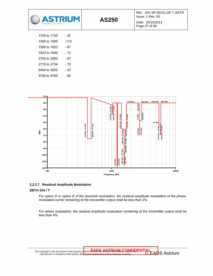
SBTA-101 / A,R
The transponder shall not transmit to the RF antenna terminal Narrow Band interference exceeding the Conducted Emission levels as defined here below:
• -12 dBm in the frequency range [10 kHz - 100 MHz],
• Conducted emission template defined by the following figure and the next table.
The above template shall be met with the transmitter ON at the exception of the TX frequency range [2200 MHz to 2290 MHz] where the transponder can exceed the CE limit with its nominal RF output power.
When the transmitter is off, the above CE template shall be met in the full frequency range [10 kHz to 10 GHz].
The next table defines the sensitive CE notches of the CE template:
Frequency range, MHz CE limit, dBm
420 to 480 - 75
1015 to 1050 - 37
1209 to 1238 -117
1425 to 1700 - 60
AS250
Ref.: DIV.SP.00151.DP.T.ASTR Issue: 1 Rev: 00
Date: 24/10/2011 Page 27 of 69
The copyright in this document is the property of EADS ASTRIUM SAS and the contents may not be reproduced or revealed to third parties without prior permission of that company in writing. © EADS Astrium
EADS ASTRIUM CONFIDENTIAL
1700 to 1720 - 22
1565 to 1585 -115
1585 to 1623 - 97
1623 to 1640 - 72
2700 to 2900 - 47
2716 to 2734 - 70
5450 to 5825 - 53
5745 to 5765 - 69
5825 MHz
5765
MH
z; -6
9 dB
m
-53 dBm
5745
MH
z; -6
9 dB
m
1565
MH
z; -1
15 d
Bm
420
MH
z; -7
5 dB
m
480
MH
z; -7
5 dB
m
1015
MH
z; -3
7 dB
m
1050
MH
z; -3
7 dB
m12
09 M
Hz
1238
MH
z14
25 M
Hz;
-60
dBm
1585
MH
z
1565
MH
z; -6
0 dB
m
1623
MH
z; -9
7 dB
m16
40 M
Hz
1700
MH
z; -6
0 dB
m
1720 MHz
2700
MH
z
2900 MHz 5450 MHz
-47
dBm
2716
MH
z
2734
MH
z29
00 M
Hz
-120
-110
-100
-90
-80
-70
-60
-50
-40
-30
-20
-10
100 1000 10000Frequency, MHz
dBm
3.2.2.7 Residual Amplitude Modulation
SBTA-104 / T
For option D or option E of the downlink modulation, the residual amplitude modulation of the phase-modulated carrier remaining at the transmitter output shall be less than 2%.
For others modulation, the residual amplitude modulation remaining at the transmitter output shall be less than 4%.

AS250
Ref.: DIV.SP.00151.DP.T.ASTR Issue: 1 Rev: 00
Date: 24/10/2011 Page 28 of 69
The copyright in this document is the property of EADS ASTRIUM SAS and the contents may not be reproduced or revealed to third parties without prior permission of that company in writing. © EADS Astrium
EADS ASTRIUM CONFIDENTIAL
3.2.2.8 Carrier Phase Noise
SBTA-106 / T
The phase noise of the unmodulated downlink carrier at nominal transmit frequency shall not exceed 3° rms integrated between 10 Hz and 1 MHz in non coherent or coherent mode when available (without uplink phase noise).
3.2.2.9 Output VSWR
SBTA-108 / T
The transmit function shall meet all performance requirements specified herein with a nominal load VSWR (antenna interface) up to 1.3 at any phase angle.
SBTA-109 / T
The transmit function when powered on shall not be damaged whatever is the VSWR at its output (open to short circuit at any phase angle (at the transponder output interface)).
This shall apply during all environmental conditions, and in particular during pressure decrease (CORONA effect) in the case of the corona-free option.
3.2.2.10 RF-Power Capability
SBTA-111 / R
In case the transmitter is specified to be ON during launch (as per option of SBTA-328), the transponder shall be corona-free. In this case, the complete transmit path shall allow RF transmission during launch phase and shall be free of any corona and multipactor effect
In the default case of a non-corona-free receiver (Tx OFF during launch), the transponder shall remain Multipactor free and it shall be possible to switch ON the receiver at satellite/launcher separation without any risk of corona effect. It will be assumed that at separation, the ambient pressure was below 0.1 mbar for more than 11 minutes.
3.2.2.11 Transmitter ON/OFF Switching
SBTA-113 / R
The transmitter shall be switchable ON/OFF by telecommand.
SBTA-343 / T
Additionally to this transmitter switching ON/OFF telecommand and upon specific requirement, a MUTE_ON/MUTE_OFF telecommand shall be provided to switch on or to switch off the carrier.

AS250
Ref.: DIV.SP.00151.DP.T.ASTR Issue: 1 Rev: 00
Date: 24/10/2011 Page 29 of 69
The copyright in this document is the property of EADS ASTRIUM SAS and the contents may not be reproduced or revealed to third parties without prior permission of that company in writing. © EADS Astrium
EADS ASTRIUM CONFIDENTIAL
3.2.2.12 Telemetry Modulation Performances
3.2.2.12.1 TM Interface
SBTA-116 / R
The nominal and high telemetry data rates for AS250 shall be in the range 128 kbps- 2 Mbps, corresponding to the available output bit rate at OBC interface level.
SBTA-117 / T
The telemetry input data shall consist of NRZ-M PCM Data.
SBTA-118 / T
The telemetry input signals shall be provided to the Transmitter inputs as one data bitstream and one clock signal (for BPSK, QPSK , PCM/PSK/PM or PCM/SP-L/PM)
SBTA-119 / T
The telemetry input data interface shall be implemented using SBDL interfaces in accordance with [AD01].
SBTA-120 / T
The telemetry signal shall be BPSK, QPSK, OQPSK or BPSK/PM modulated (upon TM modulation option selected) onto the down-link carrier in accordance with the requirements of [AD05].
SBTA-121 / R
The transmitter shall guarantee a minimum number of downlink switching cycles (removal of RF emission) of more than 43 000 cycles corresponding to 5000 cycles on ground and 38 000 cyles in orbit.
The switching cycle is defined as sequential Switch OFF and Switch ON of transmitter or sequential Mute ON & Mute OFF on the Transmitter.
The transmitter switch OFF being achieved by sequential external transmitter power supply OFF then internal Transmitter relay switch OFF.
The transmitter Switch ON being achieved by sequential internal Transmitter relay switch ON then external transmitter power supply ON.
3.2.2.12.2 Occupied Bandwidth
SBTA-123 / T
The occupied bandwidth 90% shall be limited as per:
For TM frequency, this requirement is given for a TM symbol rate instead of a TM bit rate as the occupied bandwidth depends on the modulation selected.
=> 300 KHz, for Rs(1) lower than 10 Ksps (except for SP-L),
=> 1200 KHz or 30 x Rs(1) whichever is smaller for Rs > 10 Ksps and < 60 Ksps (except for SP-L),
=> 1200 KHz or 12 x Rs(1) whichever is larger up to 6 MHz for Rs > 60 Ksps and < 2 Msps(2).
=> 1,1 x Rs(1) up to 6 MHz for Rs > 2Msps.

AS250
Ref.: DIV.SP.00151.DP.T.ASTR Issue: 1 Rev: 00
Date: 24/10/2011 Page 30 of 69
The copyright in this document is the property of EADS ASTRIUM SAS and the contents may not be reproduced or revealed to third parties without prior permission of that company in writing. © EADS Astrium
EADS ASTRIUM CONFIDENTIAL
Note 1 : Rs is the TM symbol rate.
Note 2 : The maximum rate available between the OBC and the transponder is 2 Mbps.
In case of ranging option selected, the corresponding occupied bandwidth shall be 2.5 time the major tone frequency selected.
Note however that the RG BW is digital and the selection of the filter is discrete over a filter selection bank so it has to be adapted to each program, besides there is no additional filtering possible if the rate for TM exceeds the RG BW in one mode of a program.
Note: SP-L is expected as the ECSS definition is as per unfiltered SP-L rectangular pulse. Then the occupied BW is bigger, either for unfiltered SP-L (recommended as per lowest loss) or filtered SP-L since the PM modulation process will increase the lines of the modulated signal having similar upper limit emission compared to the unfiltered case.
3.2.2.12.3 Carrier Suppression.
SBTA-125 / T
The carrier suppression shall be better than 30 dBc in accordance with the requirement in [AD05].
3.2.2.12.4 RF INTERFACE
SBTA-127 / A,R
The RF interface shall be a SMA female connector.
The impedance of the Transponder RF Interface is 50 ohms with a maximum VSWR of 1.3 in +/-10 MHz around receive and transmit frequencies.
3.2.3 General Transponder Requirements
3.2.3.1 Switch-On / Warm-up Requirements
SBTA-130 / T
For the whole range of temperature, the Transponder performances shall be reached after a warm-up time not exceeding 5 minutes, including the receiver rest frequency and transmitter frequency activation within their specified values.
3.2.3.2 Launch Mode
SBTA-132 / R
During launch the receivers shall be on.
SBTA-328 / T
The transmitters design shall allow operation during launch. For each specific mission, the transmitter state (ON or OFF) during launch shall be specified in the specific project delta-specification.

AS250
Ref.: DIV.SP.00151.DP.T.ASTR Issue: 1 Rev: 00
Date: 24/10/2011 Page 31 of 69
The copyright in this document is the property of EADS ASTRIUM SAS and the contents may not be reproduced or revealed to third parties without prior permission of that company in writing. © EADS Astrium
EADS ASTRIUM CONFIDENTIAL
SBTA-330 / T
Depending on the mission transmitter status during launch, the mechanical tests shall be performed with the same transmitter configuration than requested by the specific project delta-specification.
SBTA-331 / T
Depending on the mission transmitter status during launch, the EMC tests shall be performed with the same transmitter configuration than requested by the delta project specification.
3.3 Ranging Performance Requirements
For the ranging and Doppler tracking, [AD4] is fully applicable except the requirements superseded by the current requirements of this paragraph.
3.3.1 Ranging Input Signals
The ranging is only available for the option 3 of the uplink modulation and for the option D and the option E of the downlink modulation.
The RG signal will be a ranging tone (sinewave) which is PSK modulated by PCM data (ranging code). Detailed definition of the ranging function shall be as per ESA Ranging Standard [AD04].
SBTA-136 / A,R
The ranging performances requirements shall be met for an input signal, modulated or not with telecommand signal, which level is between -110 and -50 dBm, referred to the transponder input interface (at diplexer level).
SBTA-137 / T
The performances shall be valid for carrier frequency offsets of ± 140 kHz around the nominal carrier frequency.
SBTA-138 / T
Ranging and telemetry shall be able to be simultaneously active.
3.3.2 Ranging Tone Frequency
SBTA-140 / T
The ranging tone selection shall be done in accordance with §4.2.3.2 of [AD04].
SBTA-332 /
The nominal tone frequency plus and minus its expected Doppler shift value shall be selected in the range 100 kHz - 1.5 MHz as defined in the §4.2.3.2.1 of [AD04].
SBTA-333 /
Coherent and non coherent mode shall be available.

AS250
Ref.: DIV.SP.00151.DP.T.ASTR Issue: 1 Rev: 00
Date: 24/10/2011 Page 32 of 69
The copyright in this document is the property of EADS ASTRIUM SAS and the contents may not be reproduced or revealed to third parties without prior permission of that company in writing. © EADS Astrium
EADS ASTRIUM CONFIDENTIAL
In coherent mode the downlink frequency is down-converted from the uplink frequency with the 240/221 ratio.
In non coherent mode an on-board oscillator is used to generate the downlink frequency.
3.3.3 Ranging Modulation Indices
SBTA-142 / T
The Ranging Modulation Index when supported by the uplink modulation option and by the downlink modulation option shall be defined at manufacturing and shall be compliant to the ranging index defined in §4.4 and §4.5 of [AD04].
Nominally the uplink PM modulation index shall be in the range 0,5 rad - 1,4 rad.
The downlink PM modulation index shall be in the range 0,2 to 1,4 rad.
In TM +RG mode, the linear sum of the modulation indices on each subcarrier shall be lower than 1.75 rad peak.
SBTA-143 / T
The performance of the PM modulation shall be :
-modulation index stability ≤± 10% (all errors included),
-modulation index linearity versus input voltage ≤± 5% within the specified modulation index range,
-modulation index stability versus frequency ≤± 5% within the specified frequency range 100 KHz - 1,5 MHz.
3.3.4 Ranging Channel Group Delay Stability
SBTA-145 / T
The group delay shall comply to §4.5.4 of [AD04] when the ranging is applicable.
3.3.5 Ranging Video AGC
SBTA-147 / T
The §4.5.8 of [SD2] shall be applicable for the AGC.
3.3.6 Ranging Demodulation Performances
SBTA-149 / T
The ranging performances shall be compliant to the §4.6.3 of [AD04].

AS250
Ref.: DIV.SP.00151.DP.T.ASTR Issue: 1 Rev: 00
Date: 24/10/2011 Page 33 of 69
The copyright in this document is the property of EADS ASTRIUM SAS and the contents may not be reproduced or revealed to third parties without prior permission of that company in writing. © EADS Astrium
EADS ASTRIUM CONFIDENTIAL
3.3.7 Ranging Signal Polarity
SBTA-151 / T
A positive phase shift on the uplink shall give rise to a positive phase shift on the downlink.
3.3.8 Ranging ON/OFF Switching
SBTA-153 / T
The ranging modulation shall be switchable ON and OFF by separate telecommand.
3.3.9 Stability Requirement for Doppler Tracking
SBTA-155 / T
Coherent transponders used for Doppler tracking shall meet the [AD04] coherent transponders requirements with the table 2 of [AD05] for the ratio definition.
3.4 S-Band TT&C Command & Housekeeping
3.4.1 Receiver Housekeeping
3.4.1.1 AGC Telemetry
SBTA-159 / T
The receiver shall provide an AGC control voltage as a function of the received carrier power level.
SBTA-334 /
The telemetry shall be such that by means of AGC calibration curves and temperature telemetry, the actual received carrier level can be determined within ± 1dB.
SBTA-335 /
This output shall be an analog signal AN2 as defined in §3.5.4.8.2 of [AD1].
3.4.1.2 SPE Telemetry
SBTA-161 / T
The receiver shall deliver a signal, which indicates the static phase error of the spacecraft VCO.
It shall be used as transponder status signal but not for accurate frequency readings.
This signal shall be an analog signal AN2 defined in §3.5.4.8.2 of [AD1].

AS250
Ref.: DIV.SP.00151.DP.T.ASTR Issue: 1 Rev: 00
Date: 24/10/2011 Page 34 of 69
The copyright in this document is the property of EADS ASTRIUM SAS and the contents may not be reproduced or revealed to third parties without prior permission of that company in writing. © EADS Astrium
EADS ASTRIUM CONFIDENTIAL
3.4.1.3 Lock Status
SBTA-163 / T,A
The receiver shall deliver a bi-level signal indicating that it is locked to the carrier.
This output is an SBDL used as bi-level like defined in §3.5.4.2 of [AD1].
(In case of dual TC output port, this status shall be double output also).
3.4.1.4 Receiver Temperature
SBTA-165 / T,R
The receiver shall deliver a signal indicating its temperature close to the hot temperature point (To be defined by the manufacturer).
This output shall be an ANF as defined in §3.5.4.9.3 of [AD1].
3.4.1.5 RX DC/DC secondary voltage
SBTA-167 / T
The receiver shall deliver the DC/DC converter secondary voltage.
This output shall comply to the AN2 defined in §3.5.4.8.2 of [AD1].
3.4.2 Transmitter Housekeeping
3.4.2.1 Transmitter ON/OFF Telemetry
SBTA-170 / T
The transmitter shall provide a signal indicating the TX ON/OFF status.
This status shall comply to the RSA output defined in §3.5.4.11 of [AD1].
3.4.2.2 Output Power Telemetry
SBTA-172 / T
The transmitter shall provide the transmit output power level.
This output shall comply to AN2 defined in §3.5.4.8.2 of [AD1].

AS250
Ref.: DIV.SP.00151.DP.T.ASTR Issue: 1 Rev: 00
Date: 24/10/2011 Page 35 of 69
The copyright in this document is the property of EADS ASTRIUM SAS and the contents may not be reproduced or revealed to third parties without prior permission of that company in writing. © EADS Astrium
EADS ASTRIUM CONFIDENTIAL
3.4.2.3 Ranging On/Off Telemetry
SBTA-174 / T
The transponder shall provide a signal of the RG ON/OFF status when the ranging is selected.
This telemetry shall comply to the RSA output defined in §3.5.4.11 of [AD1] or to Serial TM interface USL defined in §3.5.4.4 of [AD1].
3.4.2.4 Coherent / Non-Coherent Status
SBTA-176 / T
The receiver shall provide a signal of the status of the COHERENT / NON-COHERENT command.
This telemetry shall comply to the RSA output defined in §3.5.4.11 of [AD1] or to Serial TM interface USL defined in §3.5.4.4 of [AD1].
3.4.2.5 High Bite Rate On / High Bit Rate Off
SBTA-178 / T
In the case where the transmitter provides 2 different bit rate for the telemetry, i.e. a low bit rate which is selected in order to perform simultaneous ranging and a high bit rate which is used for telemetry only without ranging, the transmitter shall provide a signal of the High Bit Rate ON / OFF status.
This telemetry shall comply to RSA output defined in §3.5.4.11 of [AD1] or to Serial TM interface USL defined in §3.5.4.4 of [AD1].
3.4.2.6 Transmitter Temperature Telemetry
SBTA-180 / T
The transmitter shall provide a signal indicating its temperature close to the hottest temperature reference point of the transmitter (TBD by the manufacturer).
This output shall comply to ANF as defined in §3.5.4.9.3 of [AD1].
3.4.2.7 Transmitter DC/DC secondary voltage telemetry
SBTA-182 / T
The transmitter shall output a DC/DC secondary voltage telemetry in order to check the DC/DC converter status of the transmitter.
The corresponding output shall comply to AN2, §3.4.5.8.2 of [AD1].

AS250
Ref.: DIV.SP.00151.DP.T.ASTR Issue: 1 Rev: 00
Date: 24/10/2011 Page 36 of 69
The copyright in this document is the property of EADS ASTRIUM SAS and the contents may not be reproduced or revealed to third parties without prior permission of that company in writing. © EADS Astrium
EADS ASTRIUM CONFIDENTIAL
3.4.2.8 Transmitter carrier ON/OFF telemetry
SBTA-347 / T
The transmitter shall provide a signal indicating the TX carrier ON/OFF status.
This status shall comply to the RSA output defined in §3.5.4.11 of [AD1] or to Serial TM interface USL defined in §3.5.4.4 of [AD1].
3.4.3 List of High Power Commands
SBTA-184 / T
Each Transponder shall accept as a minimum the following Standard High Power Commands (SHP).
·Transmitter ON (A and B) SHP
·Transmitter OFF (A and B) SHP
.Mute ON (A and B) SHP or serial CMD interface (MLC / USL) TBC.
.Mute OFF (A and B) SHP or serial CMD interface (MLC / USL) TBC.
·Coherent Mode Select, TBC (A and B) SHP or serial CMD interface (MLC / USL) TBC.
·Non-coherent Select, TBC (A and B) SHP or serial CMD interface (MLC / USL) TBC.
·Ranging ON, TBC (A and B) SHP or serial CMD interface (MLC / USL) TBC.
·Ranging OFF, TBC (A and B) SHP or serial CMD interface (MLC / USL) TBC.
.Low Bit Rate off/High Bit Rate on, TBC (A and B) SHP or serial CMD interface (MLC / USL) TBC.
.Low Bit Rate on/High Bit Rate off, TBC (A and B) SHP or serial CMD interface (MLC / USL) TBC.
The detailed interface characteristics shall be in accordance to the SHP definition, §3.5.4.10.1 of [AD01].
The detailed interface characteristics of MLC are given in §3.5.4.4 of [AD1].
The detailed interface characteristics of USL are given in §3.5.4.5 of [AD1].
Each SHP, MLC or USL command shall be provided with two redundant inputs for case of cross-strapping, TBC, shown as A and B.
3.4.4 List of Housekeeping Signals
SBTA-186 / T
The Transponder shall provide as a minimum the following housekeeping signals:
RX analog outputs O 3 AN2 Yes AGC,SPE, 2nd volt.
RX temperature O 1 ANF(1) Yes Temperature
RX logical status O 1 / 2 SBDL Yes Lock Status
TX status O 1 RSA Yes Transmitter On/Off status.

AS250
Ref.: DIV.SP.00151.DP.T.ASTR Issue: 1 Rev: 00
Date: 24/10/2011 Page 37 of 69
The copyright in this document is the property of EADS ASTRIUM SAS and the contents may not be reproduced or revealed to third parties without prior permission of that company in writing. © EADS Astrium
EADS ASTRIUM CONFIDENTIAL
TX carrier status O 1 RSA(2) Yes Mute On/Off status.
TX analog outputs O 2 AN2 Yes RF power, TX 2nd volt.
TX Temperature O 1 ANF(1) Yes TX temperature.
Ranging on/off status O 1 RSA(2) Yes Ranging mode ON or OFF
Coherent on/off status O 1 RSA(2) Yes Coherent mode ON or OFF
High Bit Rate on/off status O 1 RSA(2) Yes High Bit Rate ON or OFF
Note 1: RX and TX temperatures shall be ANF or ANY TBC. ANF and ANY are described in §3.5.4.9.
Note 2: These status shall be RSA or Serial TM interface USL depending on the corresponding command characteristics.
Each housekeeping signal shall be provided with two redundant outputs (TBC) in order to be in line with the input commands number i.e., one command, one status. Two cross-strapped commands, two statuses.

AS250
Ref.: DIV.SP.00151.DP.T.ASTR Issue: 1 Rev: 00
Date: 24/10/2011 Page 38 of 69
The copyright in this document is the property of EADS ASTRIUM SAS and the contents may not be reproduced or revealed to third parties without prior permission of that company in writing. © EADS Astrium
EADS ASTRIUM CONFIDENTIAL
4. UNIT/EQUIPMENT SPECIFIC DESIGN AND INTERFACE REQUIREMENTS
4.1 Lifetime
SBTA-383 / A,R
The lifetime shall be 7 years
4.2 Mechanical Requirements
4.2.1 Mass
SBTA-192 / T
The mass of one Transponder ( i.e. Transmitter, Receiver and Diplexer ) shall be less than 3,3 kg.
4.2.2 Centre of Gravity
SBTA-194 / A
The CoG position measurement shall be provided with ±1 cm of accuracy on the 3 axis.
4.2.3 Envelope
SBTA-196 / R
The dimensions of each Transponder housing including mounting feet and connectors shall not exceed
229 mm; 170 mm; 165 mm [length; wide; height]
4.3 Electrical Requirements
4.3.1 Power Consumption / Dissipation
SBTA-199 / T
The maximum power consumption / dissipation of each transponder shall be less than:
- for the RX only 7,5 W at 25°C,
- for the TX only 28 W at 25°C belonging to 35,5 W for the whole transponder for DC consumption at transponder primary power supply.
4.3.2 Power Interfaces
SBTA-201 / T
Each Transponder shall have two DC/DC converters, one for the Receiver and one for the Transmitter.
As soon as the main bus applies, the receiver shall be operating.
As soon as the main bus applies and the TC Transmitter ON is received, the transmitter shall enter the operating mode in the following configuration (for the transmitter which provide ranging option and dual data rate option):

AS250
Ref.: DIV.SP.00151.DP.T.ASTR Issue: 1 Rev: 00
Date: 24/10/2011 Page 39 of 69
The copyright in this document is the property of EADS ASTRIUM SAS and the contents may not be reproduced or revealed to third parties without prior permission of that company in writing. © EADS Astrium
EADS ASTRIUM CONFIDENTIAL
- RANGING OFF
- COHERENT MODE OFF,
- Low Bit Data Rate selected.
SBTA-202 / T
Each Transponder shall receive unregulated primary power for its Receiver from one FCL interface and for its transmitter from one LCL interface.
SBTA-203 / T,A
The contractor shall design its power interface to be compliant with the interface characteristics defined in [AD01].
4.3.3 Housekeeping Command & Telemetry Interfaces
SBTA-205 / R
All Standard High Power Commands (SHP) will be cross-strapped between the OBC and the Transponder.
The Transponder shall comply with the SHP cross-strapping requirement as given in §3.5.4.10.1and §3.5.6.1 of [AD1].
4.3.4 S-Band Digital TC Channel Interface
SBTA-207 / R
The S-Band Digital TC Channel output interface shall consist of 4 signals:
- the NRZ-L DATA signal,
- the CLOCK signal,
- the data valid signal and
- the RF carrier lock status.
These 4 signals are SBDL compliant to the §3.5.4.2 of AD1.
The 3 signals (NRZ-L DATA, CLOCK and data valid) are the input NRZ-L DATA signal coming on 3 discrete lines.
SBTA-208 / R
The contractor shall design his part of the interface to be compliant to the SBDL requirements defined in [AD01], §3.5.4.2 for electrical characteristics and §3.5.4.13 for timing parameters.

AS250
Ref.: DIV.SP.00151.DP.T.ASTR Issue: 1 Rev: 00
Date: 24/10/2011 Page 40 of 69
The copyright in this document is the property of EADS ASTRIUM SAS and the contents may not be reproduced or revealed to third parties without prior permission of that company in writing. © EADS Astrium
EADS ASTRIUM CONFIDENTIAL
The input timing is given on the diagram of the §3.5.4.13.1 of [AD1] with the following precision :
The clock is running as soon as the RX is powered on, not only when the RX is locked.
4.3.5 S-Band Digital TM Channel Interface
SBTA-210 / R
The possible combination of data input interfaces with modulations as per-SBTA-90 are given in the following table :
Downlink modulation option
Input Interface A B C D E
NRZ + Clock + Sub-carrier NA NA NA x NA
BPSK + Clock NA NA NA x NA
I,Q + Clock NA x x NA NA
NRZ + Clock x x x x x
'x' as interface supported for this modulation option.
See [AD01] for interfaces electrical definition.
SBTA-211 / T,R
The contractor shall design his part of the interface to be compliant to the SBDL requirements defined in [AD01] for electrical characteristics and shall comply to the §3.5.4.13.3 of [AD1] for timing parameters.
4.3.6 Software data interfaces
SBTA-325 /
If software is used the related PROM(s) shall be accessible externally to the box or patchable on ground.
4.4 Magnetic Moment
SBTA-213 / T,A
§4.5.7 of [AD1] shall be applicable for Magnetic moment.
4.5 Unit/Equipment Reliability Requirement
SBTA-215 / A
The Transponder shall run without degradation, throughout 7 years in orbit with a probability better than 0.9438 with the following assumptions :
- RX always supplied on and
- TX supplied on during 10% of the time (during the 7 years).

AS250
Ref.: DIV.SP.00151.DP.T.ASTR Issue: 1 Rev: 00
Date: 24/10/2011 Page 41 of 69
The copyright in this document is the property of EADS ASTRIUM SAS and the contents may not be reproduced or revealed to third parties without prior permission of that company in writing. © EADS Astrium
EADS ASTRIUM CONFIDENTIAL
This reliability result from the following failure rate assumptions:
- receiver : 850 fits,
- transmitter : 940 fits,
for a skin temperature of 30°C. The calculation shall be performed for 20°C, 30°C, 40°C.
SBTA-216 / A,R
The failure modes and effects analysis of the transponder shall consider the following severity categories:
Category 1:
Failure propagation outside the transponder.
Category 2:
Complete loss of the receiver
Complete loss of the emitter
Complete loss of the transponder
Degradation of the transponder functions performances.
Category 3:
Effect leading to minor impact on the mission (latent failure on protection devices, ...)
Category 4:
Effect without any operational impacts
SBTA-217 / A
No single failure within the transponder shall lead to feared event of category 1.
SBTA-218 / A
The design shall ensure that the failed function when it is switchable can be switched off from the power supply (except
cases specified).
This doesn't apply to the receiver which cannot be switched off for requirement reason.
SBTA-219 / A
For the electrical and thermal interfaces, the levels to be worst case levels are specified in the [AD1], for each interface type.

AS250
Ref.: DIV.SP.00151.DP.T.ASTR Issue: 1 Rev: 00
Date: 24/10/2011 Page 42 of 69
The copyright in this document is the property of EADS ASTRIUM SAS and the contents may not be reproduced or revealed to third parties without prior permission of that company in writing. © EADS Astrium
EADS ASTRIUM CONFIDENTIAL
4.6 Doppler Frequency
SBTA-327 /
The Doppler Frequency shift shall be considered additionally for received uplink carrier frequency, TC subcarrier frequency, TC bit rate, ranging tone, band and TM carrier frequency in coherent mode.
The Doppler Frequency shift depends on the spacecraft orbit.
Orbit characteristics (if available) will be provided by the mission prime to allow the calculation of the Doppler Frequency shift according to [AD04].
Without the specific orbit characteristics, the assumptions will assumed the worst case values.

AS250
Ref.: DIV.SP.00151.DP.T.ASTR Issue: 1 Rev: 00
Date: 24/10/2011 Page 43 of 69
The copyright in this document is the property of EADS ASTRIUM SAS and the contents may not be reproduced or revealed to third parties without prior permission of that company in writing. © EADS Astrium
EADS ASTRIUM CONFIDENTIAL
5. GENERAL DESIGN AND INTERFACE REQUIREMENTS
SBTA-223 / T,A
[AD1] shall be applicable.

AS250
Ref.: DIV.SP.00151.DP.T.ASTR Issue: 1 Rev: 00
Date: 24/10/2011 Page 44 of 69
The copyright in this document is the property of EADS ASTRIUM SAS and the contents may not be reproduced or revealed to third parties without prior permission of that company in writing. © EADS Astrium
EADS ASTRIUM CONFIDENTIAL
6. PRODUCT ASSURANCE REQUIREMENTS
Deleted

AS250
Ref.: DIV.SP.00151.DP.T.ASTR Issue: 1 Rev: 00
Date: 24/10/2011 Page 45 of 69
The copyright in this document is the property of EADS ASTRIUM SAS and the contents may not be reproduced or revealed to third parties without prior permission of that company in writing. © EADS Astrium
EADS ASTRIUM CONFIDENTIAL
7. VERIFICATION REQUIREMENTS
7.1 Required Unit/Equipment Level Tests
7.1.1 Functional/Performance Tests
SBTA-229 / T
The performance requirements defined in this specification are worst case values and shall be met through the lifetime of the spacecraft, environmental conditions. Functional and performance parameters derived from the requirements above shall be measured under relevant boundary conditions and shall include measurement accuracy.
SBTA-230 / T
The subcontractor shall demonstrate by means of functional and performance tests that there is no degradation caused by environmental testing.
7.1.2 EMC Requirements
7.1.2.1 Conducted Emission
SBTA-233 / T
§4.5.1 of [AD1] shall be applicable for EMC Conducted Emission.
7.1.2.2 Conducted susceptibility
SBTA-235 / T
§4.5.2 of [AD1] shall be applicable for EMC Conducted Susceptibility.
7.1.2.3 Radiated Emissions (E Field)
SBTA-237 / T
§4.5.3 of [AD1] shall be applicable for EMC Radiated Emissions (E field) with the following modifications :
♣ Falcon 9 : the unit shall not exceed the following radiated emissions levels:
410-430 MHz : 20dBµV/m ; 1565-1585 MHz : 20dBµV/m ; 1610-1630 MHz : 20dBµV/m ; 2025-2110 MHz : 20dBµV/m ;
5680-5700 MHz : 60dBµV/m
♣ PSLV : the unit shall not exceed the following radiated emissions levels:
429-434 MHz : 35dBµV/m ; 1570-1580 MHz : 10dBµV/m
.
7.1.2.4 Radiated Emissions (H Field)
SBTA-239 / T
§4.5.4 of [AD1] shall be applicable for EMC Radiated Emissions (H Field).
AS250
Ref.: DIV.SP.00151.DP.T.ASTR Issue: 1 Rev: 00
Date: 24/10/2011 Page 46 of 69
The copyright in this document is the property of EADS ASTRIUM SAS and the contents may not be reproduced or revealed to third parties without prior permission of that company in writing. © EADS Astrium
EADS ASTRIUM CONFIDENTIAL
7.1.2.5 Radiated Susceptibility (E Field)
SBTA-241 / T
§4.5.5 of [AD1] shall be applicable for EMC Radiated Susceptibility (E field) with the following modifications :
♣ Falcon 9 : the unit shall not show any malfunction or deviation from the specified performance when irradiated with following E-fields : 1610 - 1626 MHz : 140dBµV/m ; 2200 - 2300 MHz : 150dBµV/m ; 5755 - 5775 MHz : 163dBµV/m
♣ PSLV : the unit shall not show any malfunction or deviation from the specified performance when irradiated with following E-fields : 2000 - 2400 MHz : 134dBµV/m
7.1.2.6 Radiated Susceptibility (H field)
SBTA-243 / T
§4.5.6 of [AD1] shall be applicable for EMC Radiated Susceptibility (H field).
7.1.2.7 DC Magnetic Requirements
SBTA-245 / T
§4.5.7 of [AD1] shall be applicable for EMC DC Magnetic
7.1.2.8 ESD Susceptibility
SBTA-247 / T
§4.5.8 of [AD1] shall be applicable for EMC ESD Susceptibility.
7.1.3 Mechanical Tests
SBTA-249 / T
§5.2.1.2, §5.2.1.3 and § 5.2.1.6 of [AD1] shall be applicable for mechanical tests.
7.1.4 Thermal design environment
7.1.4.1 On-ground Phase
Refer to §4.3.1 of [AD1].
7.1.4.2 In-Orbit Phase
SBTA-254 / A
§4.3.2 of [AD1] shall be applicable.
7.1.5 Radiation Requirements
7.1.5.1 Total ionizing dose.
SBTA-257 / A
§4.4.4.1 of [AD1] shall be applicable.

AS250
Ref.: DIV.SP.00151.DP.T.ASTR Issue: 1 Rev: 00
Date: 24/10/2011 Page 47 of 69
The copyright in this document is the property of EADS ASTRIUM SAS and the contents may not be reproduced or revealed to third parties without prior permission of that company in writing. © EADS Astrium
EADS ASTRIUM CONFIDENTIAL
7.1.5.2 Non Ionising Dose
Refer to §4.4.4.2 of [AD1] for applicable conditions.
7.1.5.3 Single Event Effect
SBTA-261 / A
§4.4.4.3 of [AD1] shall be applicable.
7.1.6 Specific requirements
SBTA-263 / A
All the input/output of the transponder shall be electrically protected against external short-circuit in case of incorrect connection during validation campaign.
SBTA-264 / A
All the input/output shall be able to support bad current injection or short-circuit to higher external voltage with no damage, in accordance with the specific interface requirement of [AD1].

AS250
Ref.: DIV.SP.00151.DP.T.ASTR Issue: 1 Rev: 00
Date: 24/10/2011 Page 48 of 69
The copyright in this document is the property of EADS ASTRIUM SAS and the contents may not be reproduced or revealed to third parties without prior permission of that company in writing. © EADS Astrium
EADS ASTRIUM CONFIDENTIAL
8. ANNEX I: ............................................................................................... GDIR APPLICABILITY MATRIX
SBTA-266 /
All the requirements of [AD1] reported in the Tables below are applicable to the AS250 Transponder. The other [AD1] requirement not listed below are then not applicable.
type GDIR paragraph / GDIR Requirement AS250-X Applicability
1 Introduction and Scope1.1 Scope1.2 Guidelines2 Applicable and Reference Documents.3 General Design and interface Requirements3.1 General Design Requirements3.1.1 Lifetime
Reqt GDI-135 ApplicableReqt GDI-137 ApplicableReqt GDI-138 Applicable
3.1.2 Design SafetyReqt GDI-140 ApplicableReqt GDI-142 Applicable
3.1.3 Dependability and Safety3.1.3.1 Failure propagation
Reqt GDI-145 ApplicableReqt GDI-4506 ApplicableReqt GDI-5535 Applicable
3.1.3.2 DisconnectionReqt GDI-149 Applicable
3.1.3.3 SegregationReqt GDI-151 ApplicableReqt GDI-4723 ApplicableReqt GDI-4724 Applicable
3.1.3.4 DetectionReqt GDI-154 ApplicableReqt GDI-4725 Applicable
3.1.3.5 Failure tolerance requirementsReqt GDI-4718 ApplicableReqt GDI-4719 ApplicableReqt GDI-4720 Applicable
3.1.3.6 Single Point Failure Tolerance requirementsReqt GDI-4728 Applicable
3.1.3.7 Reliability estimationReqt GDI-5539 Applicable
3.1.4 VentingReqt GDI-159 ApplicableReqt GDI-161 Applicable
3.1.5 InterchangeabilityReqt GDI-164 Applicable
3.1.6 Identification & MarkingReqt GDI-166 ApplicableReqt GDI-167 ApplicableReqt GDI-168 Applicable
3.1.7 Accessibility/MaintainabilityReqt GDI-170 ApplicableReqt GDI-171 ApplicableReqt GDI-172 Applicable
3.1.8 Transportation, Handling and Storage3.1.8.1 Transport
Reqt GDI-175 ApplicableReqt GDI-176 ApplicableReqt GDI-177 ApplicableReqt GDI-178 Applicable
3.1.8.2 Unit PackingReqt GDI-180 ApplicableReqt GDI-181 Applicable
3.1.8.3 Container IdentificationReqt GDI-183 ApplicableReqt GDI-184 Applicable
3.1.8.4 Handling3.1.9 Materials3.1.9.1 Magnetic Materials
Reqt GDI-190 ApplicableReqt GDI-191 Applicable
3.1.9.2 Seals and Life limited items3.1.9.3 Lubricants and Sealants
Reqt GDI-196 Applicable

AS250
Ref.: DIV.SP.00151.DP.T.ASTR Issue: 1 Rev: 00
Date: 24/10/2011 Page 49 of 69
The copyright in this document is the property of EADS ASTRIUM SAS and the contents may not be reproduced or revealed to third parties without prior permission of that company in writing. © EADS Astrium
EADS ASTRIUM CONFIDENTIAL
type GDIR paragraph / GDIR Requirement AS250-X Applicability
3.1.9.4 Screw LockingReqt GDI-198 Applicable
3.1.10 Ground Support Equipments3.2 Mechanical Design and Interface Requirements
Reqt GDI-203 ApplicableReqt GDI-204 Applicable
3.2.1 Structural Design3.2.1.1 General Requirements
Reqt GDI-207 ApplicableReqt GDI-208 ApplicableReqt GDI-209 ApplicableReqt GDI-211 Applicable
3.2.1.2 Mass propertiesReqt GDI-213 ApplicableReqt GDI-240 ApplicableReqt GDI-241 Applicable
3.2.1.3 Centre of Gravity and Moment of InertiaReqt GDI-243 ApplicableReqt GDI-271 ApplicableReqt GDI-272 Applicable
3.2.1.4 Stiffness requirementReqt GDI-276 ApplicableReqt GDI-277 Applicable
3.2.1.5 Strength Requirements3.2.1.5.1 Definitions and General Requirements
Reqt GDI-280 ApplicableReqt GDI-294 Applicable
3.2.1.5.2 Margin of Safety & Safety FactorsReqt GDI-298 ApplicableReqt GDI-299 ApplicableReqt GDI-390 ApplicableReqt GDI-396 ApplicableReqt GDI-397 ApplicableReqt GDI-398 ApplicableReqt GDI-399 ApplicableReqt GDI-400 ApplicableReqt GDI-401 ApplicableReqt GDI-402 ApplicableReqt GDI-403 ApplicableReqt GDI-404 ApplicableReqt GDI-405 ApplicableReqt GDI-406 Applicable
3.2.1.6 Alignment and Stability RequirementsReqt GDI-408 Applicable
3.2.2 Design Requirements3.2.2.1 Attachment Requirements
Reqt GDI-412 ApplicableReqt GDI-413 ApplicableReqt GDI-414 ApplicableReqt GDI-415 ApplicableReqt GDI-416 ApplicableReqt GDI-417 ApplicableReqt GDI-437 ApplicableReqt GDI-438 ApplicableReqt GDI-439 ApplicableReqt GDI-440 ApplicableReqt GDI-441 ApplicableReqt GDI-442 ApplicableReqt GDI-443 Applicable
3.2.2.2 Alignment Requirements3.2.2.3 Electrical Connectors
Reqt GDI-468 ApplicableReqt GDI-469 ApplicableReqt GDI-470 Applicable
3.2.3 Mechanical Interface Control DocumentsReqt GDI-472 ApplicableReqt GDI-473 ApplicableReqt GDI-474 Applicable

AS250
Ref.: DIV.SP.00151.DP.T.ASTR Issue: 1 Rev: 00
Date: 24/10/2011 Page 50 of 69
The copyright in this document is the property of EADS ASTRIUM SAS and the contents may not be reproduced or revealed to third parties without prior permission of that company in writing. © EADS Astrium
EADS ASTRIUM CONFIDENTIAL
type GDIR paragraph / GDIR Requirement AS250-X Applicability
Reqt GDI-475 ApplicableReqt GDI-476 ApplicableReqt GDI-477 ApplicableReqt GDI-479 ApplicableReqt GDI-480 Applicable
3.2.4 Mechanical Mathematical Model RequirementsReqt GDI-483 ApplicableReqt GDI-484 Applicable
3.2.5 Mechanism Design3.2.5.1 General requirements3.2.5.2 Lifetime Requirement3.2.5.3 Torque Margin Requirements
Reqt GDI-504 ApplicableReqt GDI-505 ApplicableReqt GDI-506 Applicable
3.3 Thermal Design and Interface Requirements3.3.1 Definition of Temperatures and Terms3.3.1.1 Radiatively Controlled Unit
Reqt GDI-510 Applicable3.3.1.2 Conductively Controlled Unit
Reqt GDI-512 ApplicableReqt GDI-513 Applicable
3.3.1.3 Isothermal UnitReqt GDI-515 ApplicableReqt GDI-516 ApplicableReqt GDI-517 ApplicableReqt GDI-518 Applicable
3.3.1.4 Temperature Reference Point (TRP)Reqt GDI-520 ApplicableReqt GDI-5476 Applicable
3.3.2 Thermal Interface Requirements3.3.2.1 Conductive Interface
Reqt GDI-524 ApplicableReqt GDI-525 ApplicableReqt GDI-526 Applicable
3.3.2.2 Radiative InterfaceReqt GDI-529 ApplicableReqt GDI-530 Applicable
3.3.2.3 Internal Temperature MonitoringReqt GDI-532 ApplicableReqt GDI-533 Applicable
3.3.2.4 Units Mounted Outside Spacecraft3.3.3 Thermal Design Requirements
Reqt GDI-537 ApplicableReqt GDI-568 ApplicableReqt GDI-569 ApplicableReqt GDI-571 Applicable
3.3.4 Thermal Control3.3.4.1 General
Reqt GDI-574 ApplicableReqt GDI-575 ApplicableReqt GDI-576 ApplicableReqt GDI-577 ApplicableReqt GDI-578 ApplicableReqt GDI-579 ApplicableReqt GDI-580 ApplicableReqt GDI-581 ApplicableReqt GDI-582 ApplicableReqt GDI-583 Applicable
3.3.4.2 Thermal AnalysisReqt GDI-585 ApplicableReqt GDI-586 Applicable
3.3.5 Thermal Interface Control DocumentsReqt GDI-588 ApplicableReqt GDI-589 Applicable
3.3.6 Thermal Mathematical Model Requirements3.3.6.1 Thermal Interface Modelling
Reqt GDI-592 Applicable

AS250
Ref.: DIV.SP.00151.DP.T.ASTR Issue: 1 Rev: 00
Date: 24/10/2011 Page 51 of 69
The copyright in this document is the property of EADS ASTRIUM SAS and the contents may not be reproduced or revealed to third parties without prior permission of that company in writing. © EADS Astrium
EADS ASTRIUM CONFIDENTIAL
type GDIR paragraph / GDIR Requirement AS250-X Applicability
3.4 Optical Design and Interface Requirements3.4.1 Optical Design Requirements3.4.1.1 General Optical Design3.4.1.2 Materials3.4.1.3 Coatings3.4.1.4 Performances3.4.2 Optical Interface Requirements3.4.3 Optical Mathematical Model Requirements3.5 Electrical Design and Interface Requirements3.5.1 General Requirements
Reqt GDI-622 ApplicableReqt GDI-623 ApplicableReqt GDI-4675 Applicable
3.5.2 Power Requirements3.5.2.1 Primary Power Bus3.5.2.1.1 Unregulated Power Requirements
Reqt GDI-4839 ApplicableReqt GDI-4840 ApplicableReqt GDI-805 ApplicableReqt GDI-4674 ApplicableReqt GDI-806 ApplicableReqt GDI-4592 ApplicableReqt GDI-4590 ApplicableReqt GDI-807 ApplicableReqt GDI-808 ApplicableReqt GDI-809 ApplicableReqt GDI-810 ApplicableReqt GDI-811 ApplicableReqt GDI-4643 ApplicableReqt GDI-812 ApplicableReqt GDI-813 ApplicableReqt GDI-814 ApplicableReqt GDI-815 ApplicableReqt GDI-816 Applicable
3.5.2.1.1.1 LCL Source Circuit Interface SpecificationReqt GDI-822 ApplicableReqt GDI-823 ApplicableReqt GDI-824 ApplicableReqt GDI-825 Applicable
3.5.2.1.1.2 LCL Load Circuit Interface SpecificationReqt GDI-4648 ApplicableReqt GDI-4705 ApplicableReqt GDI-4649 ApplicableReqt GDI-836 ApplicableReqt GDI-837 ApplicableReqt GDI-838 ApplicableReqt GDI-4846 Applicable
3.5.2.1.1.3 LCL Harness Interface specification3.5.2.1.1.4 FCL Source Circuit Interface Specification
Reqt GDI-4847 ApplicableReqt GDI-4613 ApplicableReqt GDI-4614 ApplicableReqt GDI-4615 Applicable
3.5.2.1.1.5 FCL Load Circuit Interface SpecificationReqt GDI-4655 ApplicableReqt GDI-4623 ApplicableReqt GDI-4624 ApplicableReqt GDI-4625 ApplicableReqt GDI-4626 ApplicableReqt GDI-4628 Applicable
3.5.2.1.1.6 FCL Harness Interface Specification3.5.2.2 Power Consumption Requirements
Reqt GDI-918 ApplicableReqt GDI-919 ApplicableReqt GDI-920 Applicable
3.5.2.3 Tolerance to Power Bus FailuresReqt GDI-923 Applicable
3.5.2.4 Initial Electrical StatusReqt GDI-925 Applicable

AS250
Ref.: DIV.SP.00151.DP.T.ASTR Issue: 1 Rev: 00
Date: 24/10/2011 Page 52 of 69
The copyright in this document is the property of EADS ASTRIUM SAS and the contents may not be reproduced or revealed to third parties without prior permission of that company in writing. © EADS Astrium
EADS ASTRIUM CONFIDENTIAL
type GDIR paragraph / GDIR Requirement AS250-X Applicability
3.5.2.5 Special Case: Secondary Power Supplied Units3.5.3 Standard Signals3.5.3.1 General Conventions
Reqt GDI-936 ApplicableReqt GDI-937 ApplicableReqt GDI-938 ApplicableReqt GDI-939 ApplicableReqt GDI-940 ApplicableReqt GDI-941 Applicable
3.5.3.2 Harness CapacitanceReqt GDI-950 Applicable
3.5.4 Standard Interfaces3.5.4.1 MIL-STD-1553 Interfaces3.5.4.1.1 BC/RT Test Requirements3.5.4.1.1.1 Qualification Test3.5.4.1.1.2 Acceptance Test3.5.4.2 Standard Balanced Digital link (SBDL)
Reqt GDI-1182 ApplicableReqt GDI-1190 Applicable
3.5.4.2.1 SBDL Driver Inteface specificationReqt GDI-1192 ApplicableReqt GDI-1193 ApplicableReqt GDI-1194 ApplicableReqt GDI-1195 ApplicableReqt GDI-1196 ApplicableReqt GDI-1197 ApplicableReqt GDI-1198 ApplicableReqt GDI-1199 ApplicableReqt GDI-1200 ApplicableReqt GDI-1201 ApplicableReqt GDI-1202 ApplicableReqt GDI-1203 ApplicableReqt GDI-1205 ApplicableReqt GDI-1206 ApplicableReqt GDI-1207 Applicable
3.5.4.2.2 SBDL Receiver Interface SpecificationReqt GDI-1209 ApplicableReqt GDI-1210 ApplicableReqt GDI-1211 ApplicableReqt GDI-1213 ApplicableReqt GDI-1214 ApplicableReqt GDI-1215 ApplicableReqt GDI-1216 ApplicableReqt GDI-1218 ApplicableReqt GDI-1219 ApplicableReqt GDI-1220 Applicable
3.5.4.2.3 SBDL Harness Interface Specification3.5.4.3 Low Voltage Differential Signalling (LVDS)3.5.4.3.1 point-to-point LVDS link3.5.4.3.2 Multi-drop LVDS configuration3.5.4.4 UART Serial Link (USL)3.5.4.5 Memory Load Commands (MLC)3.5.4.6 Serial Data Transfer (SDT)3.5.4.7 Timing Pulses3.5.4.7.1 On-Board Time Synchronisation or Datation Pulses (PPS)3.5.4.7.2 Synchronisation Pulse Interface (SY)3.5.4.8 Housekeeping Analog Acquisitions
Reqt GDI-1286 Applicable3.5.4.8.1 Analogue Telemetry Acquisition [-5V;+5V] (AN1)3.5.4.8.1.1 Driver Circuit Interface Specification3.5.4.8.1.2 Receiver Circuit Interface Specification3.5.4.8.1.3 Harness Interface Specification3.5.4.8.2 Analogue Telemetry Acquisition [0;+5V] (AN2)3.5.4.8.2.1 Driver Circuit Interface Specification
Reqt GDI-1320 ApplicableReqt GDI-1321 ApplicableReqt GDI-1322 ApplicableReqt GDI-1323 ApplicableReqt GDI-1324 Applicable
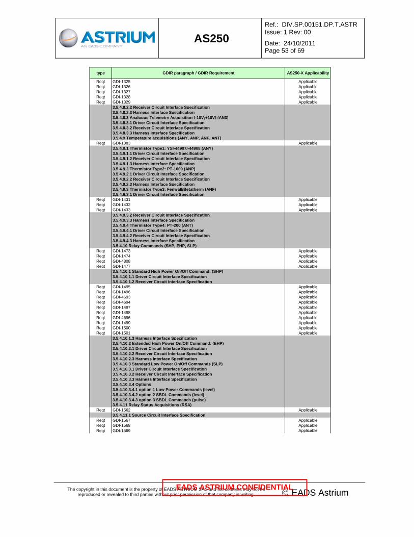
AS250
Ref.: DIV.SP.00151.DP.T.ASTR Issue: 1 Rev: 00
Date: 24/10/2011 Page 53 of 69
The copyright in this document is the property of EADS ASTRIUM SAS and the contents may not be reproduced or revealed to third parties without prior permission of that company in writing. © EADS Astrium
EADS ASTRIUM CONFIDENTIAL
type GDIR paragraph / GDIR Requirement AS250-X Applicability
Reqt GDI-1325 ApplicableReqt GDI-1326 ApplicableReqt GDI-1327 ApplicableReqt GDI-1328 ApplicableReqt GDI-1329 Applicable
3.5.4.8.2.2 Receiver Circuit Interface Specification3.5.4.8.2.3 Harness Interface Specification3.5.4.8.3 Analogue Telemetry Acquisition [-10V;+10V] (AN3)3.5.4.8.3.1 Driver Circuit Interface Specification3.5.4.8.3.2 Receiver Circuit Interface Specification3.5.4.8.3.3 Harness Interface Specification3.5.4.9 Temperature acquisitions (ANY, ANP, ANF, ANT)
Reqt GDI-1383 Applicable3.5.4.9.1 Thermistor Type1: YSI-44907/-44908 (ANY)3.5.4.9.1.1 Driver Circuit Interface Specification3.5.4.9.1.2 Receiver Circuit Interface Specification3.5.4.9.1.3 Harness Interface Specification3.5.4.9.2 Thermistor Type2: PT-1000 (ANP)3.5.4.9.2.1 Driver Circuit Interface Specification3.5.4.9.2.2 Receiver Circuit Interface Specification3.5.4.9.2.3 Harness Interface Specification3.5.4.9.3 Thermistor Type3: Fenwall/Betatherm (ANF)3.5.4.9.3.1 Driver Circuit Interface Specification
Reqt GDI-1431 ApplicableReqt GDI-1432 ApplicableReqt GDI-1433 Applicable
3.5.4.9.3.2 Receiver Circuit Interface Specification3.5.4.9.3.3 Harness Interface Specification3.5.4.9.4 Thermistor Type4: PT-200 (ANT)3.5.4.9.4.1 Driver Circuit Interface Specification3.5.4.9.4.2 Receiver Circuit Interface Specification3.5.4.9.4.3 Harness Interface Specification3.5.4.10 Relay Commands (SHP, EHP, SLP)
Reqt GDI-1473 ApplicableReqt GDI-1474 ApplicableReqt GDI-4808 ApplicableReqt GDI-1477 Applicable
3.5.4.10.1 Standard High Power On/Off Command: (SHP)3.5.4.10.1.1 Driver Circuit Interface Specification3.5.4.10.1.2 Receiver Circuit Interface Specification
Reqt GDI-1495 ApplicableReqt GDI-1496 ApplicableReqt GDI-4693 ApplicableReqt GDI-4694 ApplicableReqt GDI-1497 ApplicableReqt GDI-1498 ApplicableReqt GDI-4696 ApplicableReqt GDI-1499 ApplicableReqt GDI-1500 ApplicableReqt GDI-1501 Applicable
3.5.4.10.1.3 Harness Interface Specification3.5.4.10.2 Extended High Power On/Off Command: (EHP)3.5.4.10.2.1 Driver Circuit Interface Specification3.5.4.10.2.2 Receiver Circuit Interface Specification3.5.4.10.2.3 Harness Interface Specification3.5.4.10.3 Standard Low Power On/Off Commands (SLP)3.5.4.10.3.1 Driver Circuit Interface Specification3.5.4.10.3.2 Receiver Circuit Interface Specification3.5.4.10.3.3 Harness Interface Specification3.5.4.10.3.4 Options3.5.4.10.3.4.1 option 1 Low Power Commands (level)3.5.4.10.3.4.2 option 2 SBDL Commands (level)3.5.4.10.3.4.3 option 3 SBDL Commands (pulse)3.5.4.11 Relay Status Acquisitions (RSA)
Reqt GDI-1562 Applicable3.5.4.11.1 Source Circuit Interface Specification
Reqt GDI-1567 ApplicableReqt GDI-1568 ApplicableReqt GDI-1569 Applicable

AS250
Ref.: DIV.SP.00151.DP.T.ASTR Issue: 1 Rev: 00
Date: 24/10/2011 Page 54 of 69
The copyright in this document is the property of EADS ASTRIUM SAS and the contents may not be reproduced or revealed to third parties without prior permission of that company in writing. © EADS Astrium
EADS ASTRIUM CONFIDENTIAL
type GDIR paragraph / GDIR Requirement AS250-X Applicability
Reqt GDI-1570 ApplicableReqt GDI-1571 ApplicableReqt GDI-1572 Applicable
3.5.4.11.2 Receiver Circuit Interface Specification3.5.4.11.3 Harness Interface Specification3.5.4.12 Digital Bi-Level TM Acquisitions (BLD)
Reqt GDI-1586 ApplicableReqt GDI-1587 ApplicableReqt GDI-1588 Applicable
3.5.4.12.1 Driver Circuit Interface SpecificationReqt GDI-1592 ApplicableReqt GDI-1593 ApplicableReqt GDI-1594 ApplicableReqt GDI-1595 ApplicableReqt GDI-1596 ApplicableReqt GDI-1597 Applicable
3.5.4.12.2 Receiver Circuit Interface Specification3.5.4.12.3 Harness Interface Specification3.5.4.12.4 option SBDL status (level)
Reqt GDI-5468 ApplicableReqt GDI-5469 Applicable
3.5.4.13 COMMS Interfaces (TT&C)3.5.4.13.1 S-Band Digital TC Channel Interface
Reqt GDI-1612 ApplicableReqt GDI-1613 ApplicableReqt GDI-1615 Applicable
3.5.4.13.2 S-Band Carrier Lock Status InterfaceReqt GDI-1620 Applicable
3.5.4.13.3 S-Band Digital TM Channel InterfaceReqt GDI-1623 ApplicableReqt GDI-1624 Applicable
3.5.4.13.4 S-Band Transponder Uplink Interface3.5.4.13.4.1 Driver Circuit Interface Specification
Reqt GDI-1630 Applicable3.5.4.13.4.2 Receiver Circuit Interface Specification
Reqt GDI-1632 ApplicableReqt GDI-1634 ApplicableReqt GDI-1635 ApplicableReqt GDI-1636 Applicable
3.5.4.13.4.3 Harness Interface SpecificationReqt GDI-1638 ApplicableReqt GDI-1639 Applicable
3.5.4.13.5 S-Band Transponder Downlink Interface3.5.4.13.5.1 Driver Circuit Interface Specification
Reqt GDI-1644 ApplicableReqt GDI-1646 ApplicableReqt GDI-1647 Applicable
3.5.4.13.5.2 Receiver Circuit Interface SpecificationReqt GDI-1649 ApplicableReqt GDI-1650 Applicable
3.5.4.13.5.3 Harness Interface SpecificationReqt GDI-1652 Applicable
3.5.4.14 Pyrotechnics (PYR)3.5.4.14.1 General Concept3.5.4.14.1.1 Release Initiator Interface3.5.4.14.1.2 Safe and Arm Connector3.5.4.14.1.3 Safe plug3.5.4.14.1.4 Arming plug3.5.4.14.2 Detailed Interface Characteristics3.5.4.14.2.1 EED Source Circuit Interface Specification3.5.4.14.2.2 EED Receiver Circuit Interface Specification3.5.4.14.2.3 EED Harness Interface Specification3.5.4.14.2.4 SMD Source Circuit Interface Specification3.5.4.14.2.5 SMD Receiver Circuit Interface Specification3.5.4.14.2.6 SMD Harness Interface Specification3.5.4.14.2.7 MDD Source Circuit Interface Specification3.5.4.14.2.8 MDD Receiver Circuit Interface Specification3.5.4.14.2.9 MDD Harness Interface Specification3.5.4.15 Propulsion Interfaces

AS250
Ref.: DIV.SP.00151.DP.T.ASTR Issue: 1 Rev: 00
Date: 24/10/2011 Page 55 of 69
The copyright in this document is the property of EADS ASTRIUM SAS and the contents may not be reproduced or revealed to third parties without prior permission of that company in writing. © EADS Astrium
EADS ASTRIUM CONFIDENTIAL
type GDIR paragraph / GDIR Requirement AS250-X Applicability
3.5.4.15.1 Latch Valve Interfaces (LVC, LVS)3.5.4.15.1.1 LVC Driver Circuit Interface Specification3.5.4.15.1.2 LVC Receiver Circuit Interface Specification3.5.4.15.1.3 LVC Harness Interface Specification3.5.4.15.1.4 Latch Valve Status Interface (LVS)3.5.4.15.2 Flow Control Valve Command Interfaces (FCVC)3.5.4.15.2.1 Driver Circuit Interface Specification3.5.4.15.2.2 Receiver Circuit Interface Specification3.5.4.15.2.3 Harness Interface Specification3.5.4.15.3 Pressure Transducer Interface's (PTS, PTA)3.5.4.15.3.1 PTA Driver Circuit Interface Specification3.5.4.15.3.2 PTA Receiver Circuit Interface Specification3.5.4.15.3.3 PTA Harness Interface Specification3.5.4.15.3.4 PTS Driver Circuit Interface Specification3.5.4.15.3.5 PTS Receiver Circuit Interface Specification3.5.4.15.3.6 PTS Harness Interface Specification3.5.4.15.4 Main Engine Interface3.5.4.16 SpaceWire3.5.4.16.1 Terms, Definitions and Abbreviated Terms3.5.4.16.2 Physical Layer3.5.4.16.2.1 Cables3.5.4.16.2.2 Connectors3.5.4.16.2.3 Cable Assembly3.5.4.16.2.4 Printed Circuit Board (PCB) & Backplane Tracking3.5.4.16.3 Signal Layer3.5.4.16.3.1 Low Voltage Differential Signalling (LVDS)3.5.4.16.3.2 Failsafe Operation of LVDS3.5.4.16.3.3 Signal Coding3.5.4.16.3.4 Data Signalling Rate3.5.4.16.3.5 Skew and Jitter3.5.4.16.4 Character Layer3.5.4.16.4.1 Data Characters, Control Characters and Codes3.5.4.16.4.2 Parity Coverage3.5.4.16.4.3 First Null Token after Reset or Link Error3.5.4.16.4.4 Time Interface3.5.4.16.5 Exchange Layer3.5.4.16.5.1 Link Characters & Nominal Characters3.5.4.16.5.2 Flow Control3.5.4.16.5.4 State Machine3.5.4.16.5.5 Autostart / Link Initialisation3.5.4.16.5.6 Normal Operation3.5.4.16.5.7 Error Detection3.5.4.16.5.8 Exception Conditions3.5.4.16.5.9 Link Timing3.5.4.16.5.10 Time Distribution3.5.4.16.6 Packet Layer3.5.4.16.6.1 SpaceWire Packet Composition3.5.4.16.6.2 CCSDS Packet3.5.4.16.6.3 Science Packet3.5.4.16.6.4 Maintenance of Synchronisation on SpaceWire Packet Level3.5.4.16.6.5 Maintenance of Syncronisation on CCSDS Packet Level3.5.5 Connectors and Harness General Design Requirements3.5.5.1 Connector Types
Reqt GDI-2099 ApplicableReqt GDI-2100 ApplicableReqt GDI-2101 ApplicableReqt GDI-2102 ApplicableReqt GDI-2103 ApplicableReqt GDI-2104 ApplicableReqt GDI-2105 Applicable
3.5.5.2 Connector CharacteristicsReqt GDI-2107 ApplicableReqt GDI-2108 ApplicableReqt GDI-2109 ApplicableReqt GDI-4768 ApplicableReqt GDI-2110 ApplicableReqt GDI-4386 ApplicableReqt GDI-4387 ApplicableReqt GDI-2111 Applicable

AS250
Ref.: DIV.SP.00151.DP.T.ASTR Issue: 1 Rev: 00
Date: 24/10/2011 Page 56 of 69
The copyright in this document is the property of EADS ASTRIUM SAS and the contents may not be reproduced or revealed to third parties without prior permission of that company in writing. © EADS Astrium
EADS ASTRIUM CONFIDENTIAL
type GDIR paragraph / GDIR Requirement AS250-X Applicability
Reqt GDI-2112 ApplicableReqt GDI-2113 ApplicableReqt GDI-4391 ApplicableReqt GDI-2114 ApplicableReqt GDI-2115 ApplicableReqt GDI-4392 ApplicableReqt GDI-2116 ApplicableReqt GDI-2117 ApplicableReqt GDI-4767 Applicable
3.5.5.3 Connector MountingReqt GDI-2119 ApplicableReqt GDI-2120 ApplicableReqt GDI-2121 ApplicableReqt GDI-2122 ApplicableReqt GDI-2123 ApplicableReqt GDI-2124 Applicable
3.5.5.4 Test ConnectorsReqt GDI-2126 ApplicableReqt GDI-2127 ApplicableReqt GDI-4388 ApplicableReqt GDI-2128 ApplicableReqt GDI-4390 ApplicableReqt GDI-2129 Applicable
3.5.5.5 Harness3.5.5.6 Cable and Harness Shields3.5.6 Cross Strapping
Reqt GDI-2146 ApplicableReqt GDI-2148 ApplicableReqt GDI-2150 ApplicableReqt GDI-2151 ApplicableReqt GDI-2152 ApplicableReqt GDI-2153 Applicable
3.5.6.1 Cross-Strapping for Relay CommandsReqt GDI-2155 ApplicableReqt GDI-2157 Applicable
3.5.6.2 Cross-Strapping for Relay Status AcquisitionReqt GDI-2159 ApplicableReqt GDI-2161 Applicable
3.5.7 Electrical Interface Control DocumentReqt GDI-2163 Applicable
3.5.8 EMC Requirements3.5.8.1 Bonding
Reqt GDI-2167 ApplicableReqt GDI-2168 ApplicableReqt GDI-2169 ApplicableReqt GDI-4394 ApplicableReqt GDI-2170 ApplicableReqt GDI-2171 ApplicableReqt GDI-2172 Applicable
3.5.8.1.1 Ground Reference Rail3.5.8.1.2 Structure Parts
Reqt GDI-2179 Applicable3.5.8.1.3 Mechanical Parts
Reqt GDI-2187 ApplicableReqt GDI-2188 Applicable
3.5.8.2 Grounding and Isolation3.5.8.2.1 General
Reqt GDI-2191 ApplicableReqt GDI-2192 Applicable
3.5.8.2.2 Electrical and Electronic unit requirementReqt GDI-2194 ApplicableReqt GDI-2195 ApplicableReqt GDI-2196 ApplicableReqt GDI-2197 ApplicableReqt GDI-2198 ApplicableReqt GDI-4395 Applicable
3.5.8.2.3 Insulating materialsReqt GDI-2200 Applicable

AS250
Ref.: DIV.SP.00151.DP.T.ASTR Issue: 1 Rev: 00
Date: 24/10/2011 Page 57 of 69
The copyright in this document is the property of EADS ASTRIUM SAS and the contents may not be reproduced or revealed to third parties without prior permission of that company in writing. © EADS Astrium
EADS ASTRIUM CONFIDENTIAL
type GDIR paragraph / GDIR Requirement AS250-X Applicability
3.5.8.2.4 Thermal parts3.5.8.2.4.1 MLI3.5.8.2.4.2 Paints
Reqt GDI-2208 Applicable3.5.8.2.4.3 Heaters and Thermistors
Reqt GDI-2210 Applicable3.5.8.2.5 Primary and Secondary Power Lines3.5.8.2.5.1 Primary Power Lines
Reqt GDI-2216 ApplicableReqt GDI-4400 ApplicableReqt GDI-2218 ApplicableReqt GDI-2219 ApplicableReqt GDI-4397 ApplicableReqt GDI-4398 ApplicableReqt GDI-4399 Applicable
3.5.8.2.5.2 Secondary Power LinesReqt GDI-2222 ApplicableReqt GDI-4402 ApplicableReqt GDI-2223 ApplicableReqt GDI-2226 ApplicableReqt GDI-4404 ApplicableReqt GDI-2227 ApplicableReqt GDI-2228 Applicable
3.5.8.2.5.3 Signal InterfacesReqt GDI-2231 ApplicableReqt GDI-2232 ApplicableReqt GDI-2233 Applicable
3.5.8.2.5.4 EGSE Grounding and IsolationReqt GDI-2235 Applicable
3.5.9 Justification of Electrical Design3.5.9.1 Worst Case Analysis
Reqt GDI-2239 ApplicableReqt GDI-2240 Applicable
3.5.9.2 Success Criteria during testingReqt GDI-2242 ApplicableReqt GDI-2243 Applicable
3.5.9.3 Electrical SchematicsReqt GDI-2245 Applicable
3.6 Operations Design and Interface Requirements3.6.2 Bit / Byte Numbering Convention
Reqt GDI-2252 ApplicableReqt GDI-2254 ApplicableReqt GDI-2255 Applicable
3.6.3 Operational Functions3.6.3.1 Handling of Operational Configuration, Modes and States
Reqt GDI-2262 ApplicableReqt GDI-2263 ApplicableReqt GDI-2264 ApplicableReqt GDI-2265 ApplicableReqt GDI-2266 ApplicableReqt GDI-2267 ApplicableReqt GDI-2268 ApplicableReqt GDI-2270 Applicable
3.6.3.1.1 On-Board Software Mode Transition ManagementReqt GDI-2272 ApplicableReqt GDI-2273 ApplicableReqt GDI-2274 ApplicableReqt GDI-2275 Applicable
3.6.3.2 Commandability3.6.3.2.1 General
Reqt GDI-2280 ApplicableReqt GDI-2281 ApplicableReqt GDI-2282 ApplicableReqt GDI-2283 ApplicableReqt GDI-2285 ApplicableReqt GDI-2286 ApplicableReqt GDI-2287 ApplicableReqt GDI-2289 ApplicableReqt GDI-2292 Applicable

AS250
Ref.: DIV.SP.00151.DP.T.ASTR Issue: 1 Rev: 00
Date: 24/10/2011 Page 58 of 69
The copyright in this document is the property of EADS ASTRIUM SAS and the contents may not be reproduced or revealed to third parties without prior permission of that company in writing. © EADS Astrium
EADS ASTRIUM CONFIDENTIAL
type GDIR paragraph / GDIR Requirement AS250-X Applicability
Reqt GDI-2293 ApplicableReqt GDI-2295 ApplicableReqt GDI-2296 ApplicableReqt GDI-2297 ApplicableReqt GDI-2299 ApplicableReqt GDI-2300 Applicable
3.6.3.2.2 Command Acknowledgement and ExecutionReqt GDI-2302 ApplicableReqt GDI-2303 ApplicableReqt GDI-2305 ApplicableReqt GDI-2307 ApplicableReqt GDI-2308 ApplicableReqt GDI-2309 ApplicableReqt GDI-2311 ApplicableReqt GDI-2312 Applicable
3.6.3.2.3 Conflicting Command HandlingReqt GDI-2314 ApplicableReqt GDI-2315 Applicable
3.6.3.3 Observability3.6.3.3.1 General
Reqt GDI-2319 ApplicableReqt GDI-2321 ApplicableReqt GDI-2322 ApplicableReqt GDI-2323 ApplicableReqt GDI-2324 ApplicableReqt GDI-2325 ApplicableReqt GDI-2327 ApplicableReqt GDI-2328 ApplicableReqt GDI-2330 ApplicableReqt GDI-2332 ApplicableReqt GDI-2333 ApplicableReqt GDI-2334 ApplicableReqt GDI-2335 ApplicableReqt GDI-2336 ApplicableReqt GDI-2337 Applicable
3.6.3.3.2 Telemetry AcquisitionReqt GDI-2340 ApplicableReqt GDI-2341 ApplicableReqt GDI-2342 ApplicableReqt GDI-2343 ApplicableReqt GDI-2345 ApplicableReqt GDI-2346 ApplicableReqt GDI-2347 ApplicableReqt GDI-2348 Applicable
3.6.3.3.3 Observability of Hardware ConfigurationReqt GDI-2350 ApplicableReqt GDI-2351 ApplicableReqt GDI-2352 ApplicableReqt GDI-2353 ApplicableReqt GDI-2354 ApplicableReqt GDI-2355 Applicable
3.6.3.3.4 Observability of redundancyReqt GDI-4658 ApplicableReqt GDI-4661 ApplicableReqt GDI-4662 ApplicableReqt GDI-4659 Applicable
3.6.3.3.5 Converter observabilityReqt GDI-4663 Applicable
3.6.3.4 Mission Critical and Hazardous Functions3.6.3.5 Time Synchronisation & Datation3.6.3.6 Memory Management3.6.3.7 Autonomy3.6.3.8 Fault Management / FDIR3.6.3.8.1 Equipment/Instrument Fault Protection
Reqt GDI-2399 ApplicableReqt GDI-2400 ApplicableReqt GDI-2401 Applicable
3.6.3.8.2 Equipment/Instrument Self Checks3.6.3.8.3 Failure Detection, Isolation and Recovery (FDIR) Functions

AS250
Ref.: DIV.SP.00151.DP.T.ASTR Issue: 1 Rev: 00
Date: 24/10/2011 Page 59 of 69
The copyright in this document is the property of EADS ASTRIUM SAS and the contents may not be reproduced or revealed to third parties without prior permission of that company in writing. © EADS Astrium
EADS ASTRIUM CONFIDENTIAL
type GDIR paragraph / GDIR Requirement AS250-X Applicability
3.6.3.9 Monitoring and Surveillance RequirementsReqt TBD Applicable
3.6.4 Operational Services3.6.5 Data Interface Protocol Requirements3.6.6 Other Requirements3.6.6.1 Inputs to Design Justification File3.6.6.2 Inputs to Satellite TM/TC Database
Reqt GDI-2436 ApplicableReqt GDI-2437 Applicable
3.6.6.3 Operation ManualReqt GDI-2439 ApplicableReqt GDI-2440 Applicable
3.7 deleted4 Environment Design Requirements4.1 Atmospheric Conditions4.1.1 Humidity
Reqt GDI-2455 Applicable4.1.2 Cleanliness
Reqt GDI-2457 Applicable4.1.3 Storage time
Reqt GDI-2459 Applicable4.1.4 Pressure Environment
Reqt GDI-2462 Applicable4.1.5 Contamination
Reqt GDI-2464 Applicable4.2 Mechanical Environment4.2.1 Ground Operations Loads
Reqt GDI-2470 ApplicableReqt GDI-2481 ApplicableReqt GDI-2516 ApplicableReqt GDI-2517 ApplicableReqt GDI-2518 Applicable
4.2.2 Launch and Early Orbit Phase.4.2.2.1 Unit Quasi-Static Loads4.2.2.2 Dynamic Environment4.2.2.2.1 Sinusoidal Environment
Reqt GDI-2663 Applicable4.2.2.2.2 Unit Random Vibration Environment
Reqt GDI-2742 Applicable4.2.2.2.3 Shock Environment
Reqt GDI-2937 ApplicableReqt GDI-2938 ApplicableReqt GDI-2939 ApplicableReqt GDI-2940 ApplicableReqt GDI-2941 Applicable
4.2.3 In Orbit Phase4.2.3.1 Quasi-static Loads and thermoelastic loads
Reqt GDI-2976 ApplicableReqt GDI-2977 Applicable
4.2.3.2 Micro-vibrationsReqt GDI-2979 ApplicableReqt GDI-2980 Applicable
4.3 Thermal Environment4.3.1 On-ground phase
Reqt GDI-2987 ApplicableReqt GDI-2988 ApplicableReqt GDI-2989 Applicable
4.3.2 In-orbit phase4.3.2.1 Temperature requirements
Reqt GDI-2991 Applicable4.3.2.2 Thermal radiation4.3.2.2-1.1 Solar constant4.3.2.2-1.2 Earth albedo4.3.2.2-1.3 Earth emitted radiation4.3.2.3 Vacuum
Reqt GDI-4805 Applicable4.3.2.4 Atomic Oxygen Environment4.4 Radiation Environment4.4.1 Deleted

AS250
Ref.: DIV.SP.00151.DP.T.ASTR Issue: 1 Rev: 00
Date: 24/10/2011 Page 60 of 69
The copyright in this document is the property of EADS ASTRIUM SAS and the contents may not be reproduced or revealed to third parties without prior permission of that company in writing. © EADS Astrium
EADS ASTRIUM CONFIDENTIAL
type GDIR paragraph / GDIR Requirement AS250-X Applicability
4.4.2 Deleted4.4.3 Deleted4.4.3.1 Deleted4.4.3.2 Deleted4.4.3.3 Deleted4.4.4 Radiation Requirements applicable to ASTROSAT 250
Reqt GDI-4599 ApplicableReqt GDI-4600 ApplicableReqt GDI-4601 ApplicableReqt GDI-4602 ApplicableReqt GDI-4603 ApplicableReqt GDI-4604 ApplicableReqt GDI-4605 ApplicableReqt GDI-4606 ApplicableReqt GDI-4607 ApplicableReqt GDI-4608 ApplicableReqt GDI-3054 ApplicableReqt GDI-3055 Applicable
4.4.4.1 Total DoseReqt GDI-3057 ApplicableReqt GDI-3058 ApplicableReqt GDI-3059 Applicable
4.4.4.2 Displacement DamageReqt GDI-3061 ApplicableReqt GDI-3062 ApplicableReqt GDI-3063 Applicable
4.4.4.3 Single Event EffectReqt GDI-3065 ApplicableReqt GDI-3069 ApplicableReqt GDI-3072 ApplicableReqt GDI-4700 ApplicableReqt GDI-4701 ApplicableReqt GDI-4712 Applicable
4.5 EMC Environment4.5.1 Conducted Emissions4.5.1.1 Inrush Current
Reqt GDI-3077 Applicable4.5.1.2 Voltage Transients
Reqt GDI-3079 ApplicableReqt GDI-3081 Applicable
4.5.1.3 Conducted Emissions on Power Leads, Frequency DomainReqt GDI-3083 ApplicableReqt GDI-3085 ApplicableReqt GDI-3087 Applicable
4.5.1.4 Conducted Emissions on Power Leads, Time DomainReqt GDI-3090 ApplicableReqt GDI-3091 Applicable
4.5.1.5 Conducted Emissions in case of failureReqt GDI-3093 Applicable
4.5.1.6 Conducted Emissions on Secondary Power Lines4.5.1.6.1 CE for secondary power supply units, Frequency Domain4.5.1.6.2 CE for secondary power supply units, Time Domain4.5.1.7 Conducted Emissions on Signal Bundles, Common Mode
Reqt GDI-3101 Applicable4.5.2 Conducted Susceptibility4.5.2.1 CS Sine Wave, Differential Mode on power lines
Reqt GDI-3105 ApplicableReqt GDI-4589 Applicable
4.5.2.2 CS Sine Wave, Common Mode on power linesReqt GDI-3107 ApplicableReqt GDI-4411 ApplicableReqt GDI-4413 ApplicableReqt GDI-4414 Applicable
4.5.2.3 CS Transient on power linesReqt GDI-3109 Applicable
4.5.2.4 CS on secondary power lines4.5.2.4.1 CS Sinewave injection for secondary power supply units4.5.2.4.2 Requirement at subsystem or system level4.5.3 Radiated Emissions (E field)

AS250
Ref.: DIV.SP.00151.DP.T.ASTR Issue: 1 Rev: 00
Date: 24/10/2011 Page 61 of 69
The copyright in this document is the property of EADS ASTRIUM SAS and the contents may not be reproduced or revealed to third parties without prior permission of that company in writing. © EADS Astrium
EADS ASTRIUM CONFIDENTIAL
type GDIR paragraph / GDIR Requirement AS250-X Applicability
Reqt GDI-3166 Applicable4.5.4 Radiated Emissions (H field)
Reqt GDI-3227 Applicable4.5.5 Radiated Susceptibility (E field)
Reqt GDI-3230 ApplicableReqt GDI-3231 Applicable
4.5.6 Radiated Susceptibility (H field)Reqt GDI-3313 ApplicableReqt GDI-3314 Applicable
4.5.7 DC Magnetic RequirementsReqt GDI-3317 ApplicableReqt GDI-3319 ApplicableReqt GDI-3321 ApplicableReqt GDI-4406 ApplicableReqt GDI-3322 ApplicableReqt GDI-4405 Applicable
4.5.8 ESD SusceptibilityReqt GDI-3325 ApplicableReqt GDI-4575 Applicable
5 Unit Level Environment Test Requirements5.1 General5.1.1 Test Definition5.1.1.1 Qualification tests
Reqt GDI-3330 Applicable5.1.1.2 Acceptance Tests
Reqt GDI-3332 Applicable5.1.1.3 Functional Performance Tests
Reqt GDI-3334 Applicable5.1.2 Test Facilities Requirements
Reqt GDI-3336 Applicable5.1.2.1 Accuracy of Test Instrumentation
Reqt GDI-3338 Applicable5.1.2.2 Tolerances of Test Parameters
Reqt GDI-3340 Applicable5.1.2.2.1 Temperature5.1.2.2.2 Pressure5.1.2.2.3 Relative Humidity5.1.2.2.4 Acceleration5.1.2.2.5 Vibration Frequency5.1.2.2.6 Vibration Level5.1.2.2.7 Acoustic Noise5.1.2.2.8 Test Duration Time5.1.2.2.9 Shock5.1.2.2.10 Solar simulation5.1.2.2.11 Balancing5.1.2.2.12 Others5.1.2.3 Facility Ambient Condition
Reqt GDI-3541 Applicable5.1.3 Test Execution
Reqt GDI-3543 Applicable5.1.4 Success Criteria
Reqt GDI-3545 Applicable5.2 Unit Tests
Reqt GDI-3547 ApplicableReqt GDI-3590 ApplicableReqt GDI-3591 Applicable
5.2.1 Mechanical Environment Tests5.2.1.1 Vibration Test Set Up
Reqt GDI-3594 ApplicableReqt GDI-3595 ApplicableReqt GDI-3596 ApplicableReqt GDI-3597 Applicable
5.2.1.2 Test FixtureReqt GDI-3600 ApplicableReqt GDI-3601 ApplicableReqt GDI-3602 ApplicableReqt GDI-3603 Applicable
5.2.1.3 Frequency SearchReqt GDI-3605 ApplicableReqt GDI-3607 Applicable
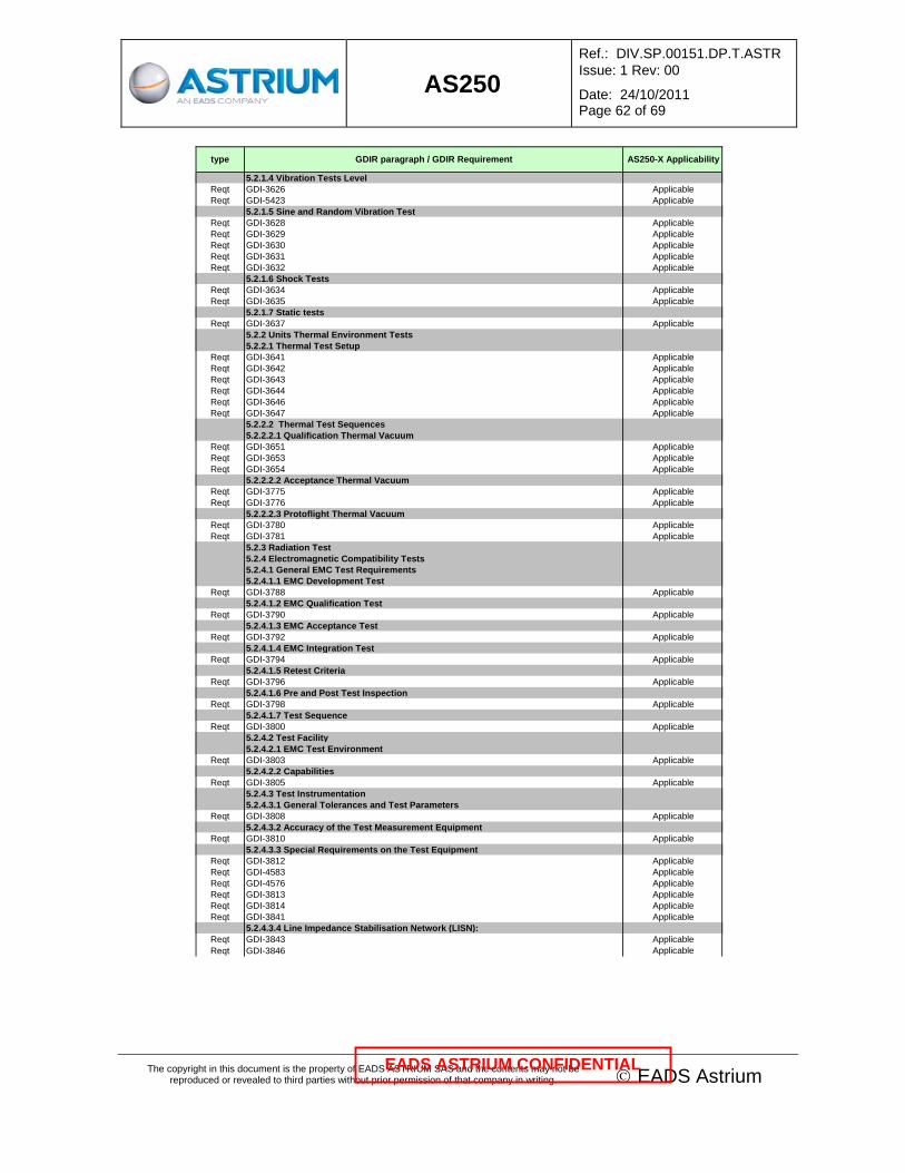
AS250
Ref.: DIV.SP.00151.DP.T.ASTR Issue: 1 Rev: 00
Date: 24/10/2011 Page 62 of 69
The copyright in this document is the property of EADS ASTRIUM SAS and the contents may not be reproduced or revealed to third parties without prior permission of that company in writing. © EADS Astrium
EADS ASTRIUM CONFIDENTIAL
type GDIR paragraph / GDIR Requirement AS250-X Applicability
5.2.1.4 Vibration Tests LevelReqt GDI-3626 ApplicableReqt GDI-5423 Applicable
5.2.1.5 Sine and Random Vibration TestReqt GDI-3628 ApplicableReqt GDI-3629 ApplicableReqt GDI-3630 ApplicableReqt GDI-3631 ApplicableReqt GDI-3632 Applicable
5.2.1.6 Shock TestsReqt GDI-3634 ApplicableReqt GDI-3635 Applicable
5.2.1.7 Static testsReqt GDI-3637 Applicable
5.2.2 Units Thermal Environment Tests5.2.2.1 Thermal Test Setup
Reqt GDI-3641 ApplicableReqt GDI-3642 ApplicableReqt GDI-3643 ApplicableReqt GDI-3644 ApplicableReqt GDI-3646 ApplicableReqt GDI-3647 Applicable
5.2.2.2 Thermal Test Sequences5.2.2.2.1 Qualification Thermal Vacuum
Reqt GDI-3651 ApplicableReqt GDI-3653 ApplicableReqt GDI-3654 Applicable
5.2.2.2.2 Acceptance Thermal VacuumReqt GDI-3775 ApplicableReqt GDI-3776 Applicable
5.2.2.2.3 Protoflight Thermal VacuumReqt GDI-3780 ApplicableReqt GDI-3781 Applicable
5.2.3 Radiation Test5.2.4 Electromagnetic Compatibility Tests5.2.4.1 General EMC Test Requirements5.2.4.1.1 EMC Development Test
Reqt GDI-3788 Applicable5.2.4.1.2 EMC Qualification Test
Reqt GDI-3790 Applicable5.2.4.1.3 EMC Acceptance Test
Reqt GDI-3792 Applicable5.2.4.1.4 EMC Integration Test
Reqt GDI-3794 Applicable5.2.4.1.5 Retest Criteria
Reqt GDI-3796 Applicable5.2.4.1.6 Pre and Post Test Inspection
Reqt GDI-3798 Applicable5.2.4.1.7 Test Sequence
Reqt GDI-3800 Applicable5.2.4.2 Test Facility5.2.4.2.1 EMC Test Environment
Reqt GDI-3803 Applicable5.2.4.2.2 Capabilities
Reqt GDI-3805 Applicable5.2.4.3 Test Instrumentation5.2.4.3.1 General Tolerances and Test Parameters
Reqt GDI-3808 Applicable5.2.4.3.2 Accuracy of the Test Measurement Equipment
Reqt GDI-3810 Applicable5.2.4.3.3 Special Requirements on the Test Equipment
Reqt GDI-3812 ApplicableReqt GDI-4583 ApplicableReqt GDI-4576 ApplicableReqt GDI-3813 ApplicableReqt GDI-3814 ApplicableReqt GDI-3841 Applicable
5.2.4.3.4 Line Impedance Stabilisation Network (LISN):Reqt GDI-3843 ApplicableReqt GDI-3846 Applicable

AS250
Ref.: DIV.SP.00151.DP.T.ASTR Issue: 1 Rev: 00
Date: 24/10/2011 Page 63 of 69
The copyright in this document is the property of EADS ASTRIUM SAS and the contents may not be reproduced or revealed to third parties without prior permission of that company in writing. © EADS Astrium
EADS ASTRIUM CONFIDENTIAL
type GDIR paragraph / GDIR Requirement AS250-X Applicability
5.2.4.3.5 Test ConditionsReqt GDI-3850 ApplicableReqt GDI-3851 ApplicableReqt GDI-3852 ApplicableReqt GDI-3853 ApplicableReqt GDI-3854 ApplicableReqt GDI-3855 ApplicableReqt GDI-3856 ApplicableReqt GDI-4577 ApplicableReqt GDI-4579 ApplicableReqt GDI-4580 ApplicableReqt GDI-4581 ApplicableReqt GDI-4582 Applicable
5.2.4.3.6 Susceptibility Testing5.2.4.4 Specific EMC Test Requirement5.2.4.4.1 Electrical Bonding
Reqt GDI-3862 ApplicableReqt GDI-3863 ApplicableReqt GDI-3864 Applicable
5.2.4.4.2 IsolationReqt GDI-3866 ApplicableReqt GDI-3867 Applicable
5.2.4.4.3 Conducted Emissions on Power Lines5.2.4.4.3.1 CE on Primary Power Lines
Reqt GDI-3871 ApplicableReqt GDI-3872 ApplicableReqt GDI-3874 Applicable
5.2.4.4.3.2 CE on Secondary Power Lines5.2.4.4.4 Conducted Emissions on Signal Bundles
Reqt GDI-3885 Applicable5.2.4.4.5 Conducted Susceptibility on Power Lines
Reqt GDI-3888 ApplicableReqt GDI-3889 ApplicableReqt GDI-4585 ApplicableReqt GDI-4587 Applicable
5.2.4.4.6 Conducted Susceptibility on Secondary Power Lines5.2.4.4.7 Radiated Emission, Electric Field
Reqt GDI-3904 Applicable5.2.4.4.8 Radiated Emission, Magnetic Field
Reqt GDI-3908 Applicable5.2.4.4.9 Radiated Susceptibility, Electric Field
Reqt GDI-3911 ApplicableReqt GDI-3912 Applicable
5.2.4.4.10 Radiated Susceptibility, Magnetic FieldReqt GDI-3915 ApplicableReqt GDI-3916 Applicable
5.2.4.4.11 Electrostatic Discharge (ESD)Reqt GDI-3919 ApplicableReqt GDI-3920 Applicable
5.2.4.4.12 Magnetic MomentReqt GDI-3924 ApplicableReqt GDI-3926 Applicable
5.2.5 Life TestReqt GDI-3938 ApplicableReqt GDI-3939 ApplicableReqt GDI-3940 ApplicableReqt GDI-3941 Applicable
5.2.6 Space ConditioningReqt GDI-3969 ApplicableReqt GDI-3970 ApplicableReqt GDI-3971 Applicable
6 Appendix A : MICD6.1 Mechanical Interface Datasheet
Reqt GDI-3974 Applicable7 APPENDIX B : TICD7.1 Thermal Interface Control Document
Reqt GDI-4108 Applicable8 APPENDIX C : EICD8.1 Electrical Interface Datasheets (Format)

AS250
Ref.: DIV.SP.00151.DP.T.ASTR Issue: 1 Rev: 00
Date: 24/10/2011 Page 64 of 69
The copyright in this document is the property of EADS ASTRIUM SAS and the contents may not be reproduced or revealed to third parties without prior permission of that company in writing. © EADS Astrium
EADS ASTRIUM CONFIDENTIAL
type GDIR paragraph / GDIR Requirement AS250-X Applicability
9 APPENDIX D : DOUBLE INSULATION TECHNOLOGICAL GUIDELINE9.1 PRINCIPLE9.2 DESIGN RULES10 APPENDIX E : FPGA / ASIC Design & Validation Requirements10.1 Timing DomainS
Reqt GDI-4285 ApplicableReqt GDI-4286 ApplicableReqt GDI-4287 ApplicableReqt GDI-4288 ApplicableReqt GDI-4289 ApplicableReqt GDI-4290 ApplicableReqt GDI-4291 Applicable
10.2 ClocksReqt GDI-4293 ApplicableReqt GDI-4294 ApplicableReqt GDI-4295 Applicable
10.3 InputsReqt GDI-4297 ApplicableReqt GDI-4298 Applicable
10.4 Asynchronous InputsReqt GDI-4300 ApplicableReqt GDI-4301 ApplicableReqt GDI-4302 ApplicableReqt GDI-4303 Applicable
10.5 OutputsReqt GDI-4305 ApplicableReqt GDI-4306 ApplicableReqt GDI-4307 ApplicableReqt GDI-4308 ApplicableReqt GDI-4309 Applicable
10.6 ResetReqt GDI-4311 ApplicableReqt GDI-4312 ApplicableReqt GDI-4313 Applicable
10.7 Internal Logic DesignReqt GDI-4315 ApplicableReqt GDI-4316 ApplicableReqt GDI-4317 ApplicableReqt GDI-4318 ApplicableReqt GDI-4319 ApplicableReqt GDI-4320 ApplicableReqt GDI-4321 ApplicableReqt GDI-4322 Applicable
10.8 State Machines and SEUReqt GDI-4324 ApplicableReqt GDI-4325 ApplicableReqt GDI-4326 Applicable
10.9 TimingReqt GDI-4328 ApplicableReqt GDI-4329 ApplicableReqt GDI-4330 ApplicableReqt GDI-4331 ApplicableReqt GDI-4332 ApplicableReqt GDI-4333 ApplicableReqt GDI-4334 ApplicableReqt GDI-4335 ApplicableReqt GDI-4336 ApplicableReqt GDI-4337 ApplicableReqt GDI-4338 ApplicableReqt GDI-4339 Applicable
10.10 Sensitive SignalsReqt GDI-4341 ApplicableReqt GDI-4342 Applicable
10.11 Pin and Size MarginReqt GDI-4344 Applicable
10.12 Design DatabaseReqt GDI-4346 ApplicableReqt GDI-4347 ApplicableReqt GDI-4348 Applicable

AS250
Ref.: DIV.SP.00151.DP.T.ASTR Issue: 1 Rev: 00
Date: 24/10/2011 Page 65 of 69
The copyright in this document is the property of EADS ASTRIUM SAS and the contents may not be reproduced or revealed to third parties without prior permission of that company in writing. © EADS Astrium
EADS ASTRIUM CONFIDENTIAL
type GDIR paragraph / GDIR Requirement AS250-X Applicability
10.13 Manufacturer’s / Vendor’s RecommendationsReqt GDI-4350 ApplicableReqt GDI-4351 ApplicableReqt GDI-4352 ApplicableReqt GDI-4353 Applicable
10.14 FPGA / ASIC ValidationReqt GDI-4356 ApplicableReqt GDI-4357 ApplicableReqt GDI-4358 ApplicableReqt GDI-4359 ApplicableReqt GDI-4360 ApplicableReqt GDI-4361 ApplicableReqt GDI-4362 ApplicableReqt GDI-4363 ApplicableReqt GDI-4364 ApplicableReqt GDI-4365 ApplicableReqt GDI-4366 ApplicableReqt GDI-4367 ApplicableReqt GDI-4368 ApplicableReqt GDI-4369 ApplicableReqt GDI-4370 ApplicableReqt GDI-4371 ApplicableReqt GDI-4372 ApplicableReqt GDI-4373 ApplicableReqt GDI-4374 ApplicableReqt GDI-4375 ApplicableReqt GDI-4376 ApplicableReqt GDI-4377 ApplicableReqt GDI-4378 ApplicableReqt GDI-4379 Applicable
11 APPENDIX F NIEL TABLES FOR PROTONS AND ELECTRONS11.1 NIEL for protons in SILICON
Reqt GDI-4759 Applicable11.2 NIEL for electrons in SILICON
Reqt GDI-4761 Applicable11.3 NIEL for protons in AsGA
Reqt GDI-4766 Applicable11.4 NIEL for electrons in AsGA
Reqt GDI-4765 Applicable

AS250
Ref.: DIV.SP.00151.DP.T.ASTR Issue: 1 Rev: 00
Date: 24/10/2011 Page 66 of 69
The copyright in this document is the property of EADS ASTRIUM SAS and the contents may not be reproduced or revealed to third parties without prior permission of that company in writing. © EADS Astrium
EADS ASTRIUM CONFIDENTIAL
9. ABBREVIATIONS LIST
A Analysis
ADM Atmospheric Dynamic Mission
AIT Assembly, Integration & Test
ATP Authorisation to Proceed
CoG Centre of Gravity
D Definition
EMC Electromagnetic Compatibility
ESA European Space Agency
FCL Fold back Current Limiter
FOV Field of View
GDIR General Design and Interface Requirements Specification
I Inspection
ICD Interface Control Document
Id Identifier
LCL Latching Current Limiter
LHC Left Handed Circular
NWP Numerical Weather Prediction
R Review of Design
RF Radio Frequency
RHC Right Handed Circular
RX Receiver
S Similarity
S/C Spacecraft
SDS Satellite Design Specification
T Test
TBC To Be Confirmed
TBD To Be Defined
TC Telecommand
TM Telemetry
TT&C Tracking, Telemetry & Command
TX Transmitter
VSWR Voltage Standing Wave Ratio

AS250
Ref.: DIV.SP.00151.DP.T.ASTR Issue: 1 Rev: 00
Date: 24/10/2011 Page 67 of 69
The copyright in this document is the property of EADS ASTRIUM SAS and the contents may not be reproduced or revealed to third parties without prior permission of that company in writing. © EADS Astrium
EADS ASTRIUM CONFIDENTIAL
Requirement/Section Cross Reference Page numbers are the pages where the sections start
SBTA-30............. 3.1....................13 SBTA-31............. 3.1....................13 SBTA-32............. 3.1....................13 SBTA-33............. 3.1....................13 SBTA-39............. 3.2.1.1..............13 SBTA-41............. 3.2.1.2..............14 SBTA-42............. 3.2.1.2..............14 SBTA-44............. 3.2.1.2..............14 SBTA-46............. 3.2.1.3..............15 SBTA-48............. 3.2.1.4..............15 SBTA-52............. 3.2.1.5..............15 SBTA-53............. 3.2.1.5..............15 SBTA-55............. 3.2.1.6..............16 SBTA-57............. 3.2.1.7..............16 SBTA-60............. 3.2.1.8..............17 SBTA-63............. 3.2.1.9..............18 SBTA-65............. 3.2.1.10............18 SBTA-69............. 3.2.1.11.2.........19 SBTA-72............. 3.2.1.11.4.........21 SBTA-75............. 3.2.1.11.5.........22 SBTA-77............. 3.2.1.11.6.........22 SBTA-84............. 3.2.2.1..............22 SBTA-86............. 3.2.2.3..............23 SBTA-87............. 3.2.2.3..............23 SBTA-88............. 3.2.2.3..............23 SBTA-89............. 3.2.2.3..............23 SBTA-90............. 3.2.2.3..............23 SBTA-91............. 3.2.2.3..............23 SBTA-94............. 3.2.2.4..............25 SBTA-96............. 3.2.2.5..............25 SBTA-97............. 3.2.2.5..............25 SBTA-99............. 3.2.2.5..............25 SBTA-101........... 3.2.2.6..............26 SBTA-104........... 3.2.2.7..............27 SBTA-106........... 3.2.2.8..............28 SBTA-108........... 3.2.2.9..............28 SBTA-109........... 3.2.2.9..............28 SBTA-111........... 3.2.2.10............28 SBTA-113........... 3.2.2.11............28 SBTA-116........... 3.2.2.12.1.........29 SBTA-117........... 3.2.2.12.1.........29 SBTA-118........... 3.2.2.12.1.........29 SBTA-119........... 3.2.2.12.1.........29 SBTA-120........... 3.2.2.12.1.........29 SBTA-121........... 3.2.2.12.1.........29 SBTA-123........... 3.2.2.12.2.........29 SBTA-125........... 3.2.2.12.3.........30 SBTA-127........... 3.2.2.12.4.........30 SBTA-130........... 3.2.3.1..............30 SBTA-132........... 3.2.3.2..............30 SBTA-136........... 3.3.1.................31 SBTA-137........... 3.3.1.................31 SBTA-138........... 3.3.1.................31 SBTA-140........... 3.3.2.................31 SBTA-142........... 3.3.3.................32 SBTA-143........... 3.3.3.................32
SBTA-145 ...........3.3.4 ................ 32 SBTA-147 ...........3.3.5 ................ 32 SBTA-149 ...........3.3.6 ................ 32 SBTA-151 ...........3.3.7 ................ 33 SBTA-153 ...........3.3.8 ................ 33 SBTA-155 ...........3.3.9 ................ 33 SBTA-159 ...........3.4.1.1 ............. 33 SBTA-161 ...........3.4.1.2 ............. 33 SBTA-163 ...........3.4.1.3 ............. 34 SBTA-165 ...........3.4.1.4 ............. 34 SBTA-167 ...........3.4.1.5 ............. 34 SBTA-170 ...........3.4.2.1 ............. 34 SBTA-172 ...........3.4.2.2 ............. 34 SBTA-174 ...........3.4.2.3 ............. 35 SBTA-176 ...........3.4.2.4 ............. 35 SBTA-178 ...........3.4.2.5 ............. 35 SBTA-180 ...........3.4.2.6 ............. 35 SBTA-182 ...........3.4.2.7 ............. 35 SBTA-184 ...........3.4.3 ................ 36 SBTA-186 ...........3.4.4 ................ 36 SBTA-189 ...........4.1 ................... 38 SBTA-192 ...........4.2.1 ................ 38 SBTA-194 ...........4.2.2 ................ 38 SBTA-196 ...........4.2.3 ................ 38 SBTA-199 ...........4.3.1 ................ 38 SBTA-201 ...........4.3.2 ................ 38 SBTA-202 ...........4.3.2 ................ 38 SBTA-203 ...........4.3.2 ................ 38 SBTA-205 ...........4.3.3 ................ 39 SBTA-207 ...........4.3.4 ................ 39 SBTA-208 ...........4.3.4 ................ 39 SBTA-210 ...........4.3.5 ................ 40 SBTA-211 ...........4.3.5 ................ 40 SBTA-213 ...........4.4 ................... 40 SBTA-215 ...........4.5 ................... 40 SBTA-216 ...........4.5 ................... 40 SBTA-217 ...........4.5 ................... 40 SBTA-218 ...........4.5 ................... 40 SBTA-219 ...........4.5 ................... 40 SBTA-223 ...........5 ...................... 43 SBTA-229 ...........7.1.1 ................ 45 SBTA-230 ...........7.1.1 ................ 45 SBTA-233 ...........7.1.2.1 ............. 45 SBTA-235 ...........7.1.2.2 ............. 45 SBTA-237 ...........7.1.2.3 ............. 45 SBTA-239 ...........7.1.2.4 ............. 45 SBTA-241 ...........7.1.2.5 ............. 46 SBTA-243 ...........7.1.2.6 ............. 46 SBTA-245 ...........7.1.2.7 ............. 46 SBTA-247 ...........7.1.2.8 ............. 46 SBTA-249 ...........7.1.3 ................ 46 SBTA-254 ...........7.1.4.2 ............. 46 SBTA-257 ...........7.1.5.1 ............. 46 SBTA-261 ...........7.1.5.3 ............. 47 SBTA-263 ...........7.1.6 ................ 47 SBTA-264 ...........7.1.6 ................ 47
SBTA-266 ........... 8 .......................48 SBTA-325 ........... 4.3.6 .................40 SBTA-327 ........... 4.6 ....................42 SBTA-328 ........... 3.2.3.2 ..............30 SBTA-330 ........... 3.2.3.2 ..............30 SBTA-331 ........... 3.2.3.2 ..............30 SBTA-332 ........... 3.3.2 .................31 SBTA-333 ........... 3.3.2 .................31 SBTA-334 ........... 3.4.1.1 ..............33 SBTA-335 ........... 3.4.1.1 ..............33 SBTA-341 ........... 3.2.2.5 ..............25 SBTA-343 ........... 3.2.2.11 ............28 SBTA-347 ........... 3.4.2.8 ..............36 SBTA-352 ........... 3.2.1.11.1 .........18 SBTA-353 ........... 3.2.1.11.1 .........18 SBTA-354 ........... 3.2.1.11.1 .........18 SBTA-358 ........... 3.2.1.11.4 .........21 SBTA-360 ........... 3.2.1.11.1 .........18 SBTA-383 ........... 3.2.1.11.3 .........38 SBTA-393 ........... 3.2.2.2 ..............23 SBTA-416 ........... 3.2.1.1 ..............13 SBTA-417 ........... 3.2.1.1 ..............13 SBTA-418 ........... 3.2.1.1 ..............13 SBTA-419 ........... 3.2.1.5 ..............15 SBTA-420 ........... 3.2.1.11.5 .........22 SBTA-421 ........... 3.2.1.11.7 .........22 SBTA-422 ........... 3.2.2.4 ..............25 SBTA-424 ........... 3.2.2.5 ..............25 SBTA-427 ........... 3.2.1.11.3 .........19 SBTA-428 ........... 3.2.1.7 ..............16 SBTA-430 ........... 3.2.1.11.3 .........19
AS250
Ref.: DIV.SP.00151.DP.T.ASTR Issue: 1 Rev: 00
Date: 24/10/2011 Page 68 of 69
The copyright in this document is the property of EADS ASTRIUM SAS and the contents may not be reproduced or revealed to third parties without prior permission of that company in writing. © EADS Astrium
EADS ASTRIUM CONFIDENTIAL
DOCUMENT CHANGE DETAILS
ISSUE CHANGE AUTHORITY CLASS RELEVANT INFORMATION/INSTRUCTIONS Issue 1 Initial issue for RFP in the frame of AS250 project.

AS250
Ref.: DIV.SP.00151.DP.T.ASTR Issue: 1 Rev: 00
Date: 24/10/2011 Page 69 of 69
The copyright in this document is the property of EADS ASTRIUM SAS and the contents may not be reproduced or revealed to third parties without prior permission of that company in writing. © EADS Astrium
EADS ASTRIUM CONFIDENTIAL
DISTRIBUTION LIST
Corporate use Project Controlled ConfiguredInternal
Astrium AS250 Avionics Distribution Astrium AS250 Avionics Team DistributionASTRUC Jean-Charles LECUREUX Yves
AUVERGNON Celine LEBREDONCHEL Jérôme
BARADAT Pierre MARCILLE Herve X
BISCARROS Didier MARTIN Philippe
BOUCHER Estelle X MARTINEZ Alain X
CARLIER Corinne MORANDINI Guillaume
CASPAR Raoul MOURNIAC Eric
CAZALS Serge X PALOUS Jean-Claude X
BARTOSCH Eric X PASQUET Francis
CHEVALIER Mathieu PENALVA Sonia
COSCULLUELA Valérie POQUET GOURDON Emmanuelle X
COUTY Eric X REBUFFEL Philippe
DEFENDINI Ange X SALAMI Adet
DE ZOETEN Peter SHAABAN Sami
DUMONT Patrick SOUTRIC Anne-Laure
DUMONTEUIL Maxime TABOUELLE Alain
FOURNE Brigitte TARDIVIER Raphael X
GALLAND Philippe THIBAUD Pierre
GENTY Patrick THIEUW Alain
GILLOT Bernard X AS250 Documentation manager X
KOMAR Eric AS250 Configuration manager X
LEBLOND Philippe
Astrium Product Policy Distribution
BERTHEUX Philippe
PREVOT Sylvain X
LEMERCIER Christophe X
PITZ Wolfgang
Astrium MPC
ALCINDOR Peter
BALDWIN Robert
BARRIERE Jacques