Embed Size (px)
Citation preview

BC.ASU.SP.00003
Issue 1.0Page 1 of 50
Document Autogenerated from DOORS Module : /BepiColombo Implementation Phase/Level 3 Equipment Specifications/MPB/MPO Structure Specification BC_ASU_SP_00001_MPO_structure_spec_15-8-2007.doc
MERCURY PLANETARY ORBITER STRUCTURE SPECIFICATION
CI CODE: B3210 PRIMARY DRL Refs : EN-U16
UK EXPORT CONTROL RATING : Not Listed
Rated By :
Prepared by: Date:
Checked by: Date:
Approved by: Date:
Authorised by: Date:
This document is produced under ESA contract, ESA export exemptions may therefore apply. These Technologies may require an export licence if exported from the EU
© Astrium Limited 2007
Astrium Ltd owns the copyright of this document which is supplied in confidence and which shall not be used for any purpose other than that for which it is supplied and shall not in whole or in part be reproduced, copied, or communicated
to any person without written permission from the owner.
Astrium Limited, Registered in England and Wales No. 2449259 Registered Office: Gunnels Wood Road, Stevenage, Hertfordshire, SG1 2AS, England
BC.ASU.SP.00003Issue 1.0
Page 2 of 50
Astrium Ltd owns the copyright of this document which is supplied in confidence and which shall not be used for any purpose other than that for which it is supplied and shall not in whole or in part be reproduced, copied, or communicated to any person without written permission from the owner.
BC_ASU_SP_00001_MPO_structure_spec_15-8-2007.doc
INTENTIONALLY BLANK

BC.ASU.SP.00003Issue 1.0
Page 3 of 50
Astrium Ltd owns the copyright of this document which is supplied in confidence and which shall not be used for any purpose other than that for which it is supplied and shall not in whole or in part be reproduced, copied, or communicated to any person without written permission from the owner.
BC_ASU_SP_00001_MPO_structure_spec_15-8-2007.doc
CONTENTS 1 INTRODUCTION AND SCOPE................................................................................................................. 5
1.1 Introduction ........................................................................................................................................ 5 1.2 Requirement Definition....................................................................................................................... 5
2 APPLICABLE AND REFERENCE DOCUMENTS .................................................................................... 6 2.1 Applicable Documents ....................................................................................................................... 6 2.2 Abbreviations ..................................................................................................................................... 6
3 FUNCTIONAL REQUIREMENTS ............................................................................................................. 7 3.1 System Requirement.......................................................................................................................... 7
3.1.1 Satellite Design ........................................................................................................................... 7 3.1.2 Reference Frames ...................................................................................................................... 8 3.1.3 Mission Phases........................................................................................................................... 9 3.1.4 Structure Configuration............................................................................................................... 9 3.1.5 Mass.......................................................................................................................................... 14
3.2 Interface Requirements.................................................................................................................... 15 3.2.1 Separation System Interfaces................................................................................................... 15 3.2.2 Sunshield Support Interfaces.................................................................................................... 15
3.3 Mechanical Design Requirements ................................................................................................... 15 3.3.1 Functional Requirements.......................................................................................................... 15 3.3.2 Performance Requirements...................................................................................................... 16
3.4 Electromagnetic Compatibility.......................................................................................................... 17 3.5 MGSE Requirements ....................................................................................................................... 18 3.6 Alignment Requirements.................................................................................................................. 21 3.7 Separation System Requirements ................................................................................................... 22
3.7.1 Key Features............................................................................................................................. 22 3.7.2 Summary of Separation System............................................................................................... 23 3.7.3 Interface bolt loads.................................................................................................................... 23 3.7.4 Separation System Alignment .................................................................................................. 23 3.7.5 Separation System Cup- Cone Coating.................................................................................... 23
4 GENERAL DESIGN AND INTERFACE REQUIREMENTS .................................................................... 24 4.1 Product Assurance........................................................................................................................... 24 4.2 General Design Requirements......................................................................................................... 24
4.2.1 Design Safety............................................................................................................................ 24 4.2.2 Venting...................................................................................................................................... 24 4.2.3 Identification & Marking............................................................................................................. 24 4.2.4 Transportation, Handling and Storage...................................................................................... 24 4.2.5 Parts Material and Processes................................................................................................... 25
4.3 Mechanical Design and Interface Requirements ............................................................................. 25 4.3.1 Structural Design ...................................................................................................................... 25 4.3.2 Design Requirements ............................................................................................................... 29 4.3.3 Mechanical Mathematical Model Requirements....................................................................... 30
5 ENVIRONMENT DESIGN REQUIREMENTS......................................................................................... 31 5.1 Atmospheric Conditions ................................................................................................................... 31
5.1.1 Cleanliness ............................................................................................................................... 31 5.2 Mechanical Environment.................................................................................................................. 31
5.2.1 Ground Environment................................................................................................................. 31 5.2.2 Launch and Flight Environment. ............................................................................................... 31 5.2.3 Mechanical Testing ................................................................................................................... 32
5.3 Thermal Environment....................................................................................................................... 35 6 VERIFICATION ....................................................................................................................................... 37
6.1 Verification Matrix............................................................................................................................. 37 7 GDIR Applicability Matrix......................................................................................................................... 38 8 ANNEXES ............................................................................................................................................... 46
8.1 Additional Drawings and Information ............................................................................................... 46

BC.ASU.SP.00003Issue 1.0
Page 4 of 50
Astrium Ltd owns the copyright of this document which is supplied in confidence and which shall not be used for any purpose other than that for which it is supplied and shall not in whole or in part be reproduced, copied, or communicated to any person without written permission from the owner.
BC_ASU_SP_00001_MPO_structure_spec_15-8-2007.doc
TABLES Table 3.1-1: Exploded MPO Structure Notes ................................................................................................. 11 Table 3.1-2: Flight Structural Items ................................................................................................................ 12 Table 3.1-3: Connector Brackets.................................................................................................................... 14 Table 3.3-1: MPO Structure Stiffness Matrix. ................................................................................................. 16 Table 3.3-2: MPO Structure Separation Cup/Cone Interface loads, MTM to MPO. ...................................... 17 Table 3.3-3: MPO Structure Separation Cup/Cone Interface loads, MPO to MOSIF. ................................... 17 Table 3.3-4: MPO Tank Interface loads. ........................................................................................................ 17 Table 3.6-1: Required Alignment Accuracy and Adjustment Facilities (Degrees). ....................................... 22 Table 3.6-2: Alignment Stability Requirements (Degrees). ............................................................................ 22 Table 3.7-1: Predicted Maximum Interface Bolt Loads. ................................................................................. 23 Table 4.3-1: Design Safety Factors ................................................................................................................ 27 Table 4.3-2: Design Additional Safety Factors. .............................................................................................. 28 Table 5.2-1: MPO Equipment Mass Distribution ............................................................................................ 32 Table 5.3-1: Structural Design Temperatures ................................................................................................ 36 Table 6.1-1: Verification Matrix....................................................................................................................... 37
FIGURES Figure 3.1-1: BepiColombo Assembled Primary Central Structure.................................................................. 7 Figure 3.1-2: View of MPO without MTM and MOSIF. ..................................................................................... 8 Figure 3.1-3: MPO & MCS Reference Frames................................................................................................. 9 Figure 3.1-4: Exploded View Of MPO Primary Structure ............................................................................... 10 Figure 3.5-1: Integration Configuration: MPO Hoisting .................................................................................. 19 Figure 3.5-2: Integration Configuration: MPO Hoisting at stack level ............................................................ 20 Figure 4.3-1: Load Factor Philosophy for Definition of Design Loads............................................................ 26 Figure 5.2-1: MPO Primary Structure definition. ........................................................................................... 33 Figure 5.2-2: MPO Primary Structure definition - without tanks. ................................................................... 34 Figure 8.1-1: MPO Separation Interface configuration................................................................................... 46 Figure 8.1-2: MPO Structure Geometry (1). ................................................................................................... 47 Figure 8.1-3: MPO Structure Geometry (2). ................................................................................................... 48

BC.ASU.SP.00003Issue 1.0
Page 5 of 50
Astrium Ltd owns the copyright of this document which is supplied in confidence and which shall not be used for any purpose other than that for which it is supplied and shall not in whole or in part be reproduced, copied, or communicated to any person without written permission from the owner.
BC_ASU_SP_00001_MPO_structure_spec_15-8-2007.doc
1 INTRODUCTION AND SCOPE
1.1 Introduction
BepiColombo is an Interdisciplinary Cornerstone Mission to the planet Mercury, in collaboration between ESA and ISAS/JAXA of Japan. It consists of two scientific orbiters, the Mercury Planetary Orbiter (MPO) and the Mercury Magnetospheric Orbiter (MMO), which are dedicated to the detailed study of the planet and of its magnetosphere.
This document defines the mission, performances, environment, interface and design requirements for the Mercury Transfer Module structure subsystem for the BepiColombo spacecraft.
This document gathers together all the contractually relevant requirements and constraints for the BepiColombo Mercury Planetary Orbiter (MPO) Structure and its supporting elements. This issue of the specification includes:
• the performance as well as design and interface requirements of subject hardware;
• the product assurance requirements;
• the testing and verification requirements.
1.2 Requirement Definition
Requirements within this document are shown in an italic font.
Information within this document is shown in normal font.
Each requirements is preceded by a summary line that contains the following fields, delimited by "/".
• <Doors Requirement Number> MPO-xyz. This is a unique number, assigned consecutively
• <Created From> Shows parent requirement
• <Test Method> T= Test, A = Analysis, I = Inspection, R = Review of Design
Requirement Text - If tables are considered as part of requirement they are referenced clearly in the text and inserted after and separated from the requirement table and are managed as free text attached to the identifier requirement.
Upper Links - The trace to the upper level requirements shall be managed with the following format:
• AAA-NNNN where AAA is a label associated to the upper document and NNNN the requirement identifier of this upper level.
• Or CREATED key word if the requirement has no link with upper level
All document elements, which are not presented in the format explained above are not requirements and will not be verified or tracked.
In references to GDIR requirements the section number is provided for information only. If there is any conflict between the GDIR requirement number and the section number then the requirement number takes precedence.

BC.ASU.SP.00003Issue 1.0
Page 6 of 50
Astrium Ltd owns the copyright of this document which is supplied in confidence and which shall not be used for any purpose other than that for which it is supplied and shall not in whole or in part be reproduced, copied, or communicated to any person without written permission from the owner.
BC_ASU_SP_00001_MPO_structure_spec_15-8-2007.doc
2 APPLICABLE AND REFERENCE DOCUMENTS
2.1 Applicable Documents
The Applicable Documents are listed below, and are referenced in the text with the acronym AD-x.
AD-1 General Design & Interface Requirements BC.ASD.SP.00001
AD-2 Subcontractor PA Requirements BC.ASD.SP.00018
AD-3 Mercury Planetary Orbiter Mechanical Interface Control Document BC.ASU.IF.00002
AD-4 Deleted
AD-5 Generic Mechanical Finite Element Models (FEM) Specification ASD.E.0787
AD-6 Deleted
AD-7 Deleted
AD-8 Mercury Planetary Orbiter Load synthesis document BC.ASU.RP.00008
AD-9 Environmental Requirements and Test Specification BC.ASD.SP.00002
AD-10 EMC requirements Specification BC.ASD.SP.0033
The issue valid at contract signature applies.
2.2 Abbreviations
Abbreviations and acronyms are contained in:-
Acronyms, Abbreviations & Terminology BC.EAD.LI.00003-1

BC.ASU.SP.00003Issue 1.0
Page 7 of 50
Astrium Ltd owns the copyright of this document which is supplied in confidence and which shall not be used for any purpose other than that for which it is supplied and shall not in whole or in part be reproduced, copied, or communicated to any person without written permission from the owner.
BC_ASU_SP_00001_MPO_structure_spec_15-8-2007.doc
3 FUNCTIONAL REQUIREMENTS
3.1 System Requirement
The system requirements for the MPO Structure require a design solution that minimises mass without compromising structural integrity. To this end, the expected design solution is expected to be an Aluminium sandwich panel construction.
MPO-74/CREATED/A,R
Structural distortions due to all effects shall be identified and quantified at all critical interfaces.
3.1.1 Satellite Design
At launch, the BepiColombo Mercury Composite Structure (MCS) incorporates 3 modules, the Mercury Transfer Module (MTM), the Mercury Planetary Orbiter (MPO) and the Mercury Magnetospheric Orbiter (MMO), plus the MOSIF interface structure and sunshield for the MMO. The configuration of which is shown illustratively in Figure 3.1.1.
MOSIF
MPO
MTM
LVA
MMO MMO
600
1250
1500
1540
1510
Figure 3.1.1: BepiColombo Assembled Primary Central Structure
The MTM is mounted on top of the LVA and secured by 4 low shock pyronut separation devices, which allow the BepiColombo MCS to be separated from the Soyuz Fregat upper stage, via the MTM.
The MPO is then mounted on top of the MTM via 4 low shock separation devices. The same type of low shock separation devices are used again at the top of the MPO at the 4 interfaces to the MOSIF sunshield support structure. The MOSIF sunshield support structure supports the MOSIF sunshield and the MMO. The MMO has its own spin up and separation system which attaches to the MOSIF Structure via a series of bolts.
The MPO is shown on its own, with sunshield and instruments, in Figure 3.1.2.

BC.ASU.SP.00003Issue 1.0
Page 8 of 50
Astrium Ltd owns the copyright of this document which is supplied in confidence and which shall not be used for any purpose other than that for which it is supplied and shall not in whole or in part be reproduced, copied, or communicated to any person without written permission from the owner.
BC_ASU_SP_00001_MPO_structure_spec_15-8-2007.doc
Figure 3.1.2: View of MPO without MTM and MOSIF.
3.1.2 Reference Frames
MPO-81/MPB-4043/R
The MPO design shall adopt the axis system defined in Figure 3.1.3.
MPO-82/MPB-4041/R
The MPO reference frame shall be right-handed orthogonal triads.

BC.ASU.SP.00003Issue 1.0
Page 9 of 50
Astrium Ltd owns the copyright of this document which is supplied in confidence and which shall not be used for any purpose other than that for which it is supplied and shall not in whole or in part be reproduced, copied, or communicated to any person without written permission from the owner.
BC_ASU_SP_00001_MPO_structure_spec_15-8-2007.doc
MMO
MTMMCS
LVA
+Z_mmo_mf
+X_mmo_mf
+Y_mmo_mf
+X_mpo_mf
+Z_mpo_mf+Y_mpo_mf
+Z_mcs_mf
+X_mcs_mf
+Y_mcs_mf
MOSIF
+X_mtm_mf
+Y_mtm_mf
MPO
+X_lva_mf
+Y_lva_mf
+Z_mtm_mf
+Z_lva_mf
+X_mosif_mf
+Y_mosif_mf
+Z_mosif_mf
FREGAT
MMT / MPOseparation plane
FREGATmounting plane
MPO / MOSIFseparation plane
MOSIF / MMOseparation plane
LVA / MTMseparation plane
O_mmo_mf
O_mosif_mf
O_mpo_mf
O_mtm_mfO_mcs_mf O_lva_mf
Figure 3.1.3: MPO & MCS Reference Frames
3.1.3 Mission Phases
The BepiColombo spacecraft has the following mission phases:
• Launch
• Earth escape
• Cruise
• Mercury capture
• MPO operation
3.1.4 Structure Configuration
The MPO structure is mounted on the MTM at 4 stack separation points based around a 1230mm diameter (separation nuts inside machined end fittings at the central structure corners). There are also 4 more stack separation points at the top of the MPO where the MOSIF is mounted (separation nuts inside machined end fittings at the central structure corners). The MPO is shown in the stack configuration in Figure 3.1.1.

BC.ASU.SP.00003Issue 1.0
Page 10 of 50
Astrium Ltd owns the copyright of this document which is supplied in confidence and which shall not be used for any purpose other than that for which it is supplied and shall not in whole or in part be reproduced, copied, or communicated to any person without written permission from the owner.
BC_ASU_SP_00001_MPO_structure_spec_15-8-2007.doc
MPO-1057/CREATED/R
All equipment is to be carried by Aluminium sandwich panels (±X-sides) with embedded heat-pipes. The Optical Bench panels shall be M55J CFRP faced aluminium honeycomb sandwich.
Critical items such as cameras and instruments are located on an optical bench (30mm aluminium core and 2mm CFRP facings on iso-static mounts). There are 2 tank support frames connecting the propellant tank skirts each to a sandwich panel tank floor configured within the MPO central square (items 3 and 7 in Figure 3.1.4).
To enable pre-assembly and mounting/de-mounting of the solar array, hold-downs and drive, the MPO has a dedicated solar generator support structure. The HGA interface points at the surface of the MPO panel (item 12 in Figure 3.1.4) provide support to the dedicated HGA support structure (consisting of a tripod supporting the drive mechanisms and 1 hold-down point, bipod supporting second hold-down and single strut supporting the third hold-down. The HGA support structure is not part of the MPB.
The radiator panel is likely to be constructed from a sandwich panel with 0.8mm thick commercially pure fully strain hardened aluminium skins, aluminium honeycomb core, and contain embedded heat-pipes (see requirement MPO-479).
The MPO structure and associated units are enclosed in High Temperature Multi-layered insulation (HTMLI), which is supported on a lightweight support structure. This structure does NOT form part of the MPO structure but interfaces to must be provided.
An exploded view of the MPO Structure is shown in Figure 3.1.4.
ZXY
1
2
3
41 1
1 2
8
7
6
5
1 5
1 4
1 3
9
1 6
1 0
ZXY
1
2
3
41 1
1 2
8
7
6
5
1 5
1 4
1 3
9
1 6
1 0
Figure 3.1.4: Exploded View Of MPO Primary Structure

BC.ASU.SP.00003Issue 1.0
Page 11 of 50
Astrium Ltd owns the copyright of this document which is supplied in confidence and which shall not be used for any purpose other than that for which it is supplied and shall not in whole or in part be reproduced, copied, or communicated to any person without written permission from the owner.
BC_ASU_SP_00001_MPO_structure_spec_15-8-2007.doc
Table 3.1-1: Exploded MPO Structure Notes
MTM to MPO separation brackets16Bottom floor15Optical bench14Optical bench ISM brackets13+X Panel12-Y Panel11-Y Radiator panel ( Inc Sub Panels)10MPO to MOSIF separation brackets9Solar Array Support Panel8Lower tank floor7+Y Inner panel6Accelerometer panel5-X Panel4Upper tank floor3Top floor2Top floor closure panel1NameNumber
MTM to MPO separation brackets16Bottom floor15Optical bench14Optical bench ISM brackets13+X Panel12-Y Panel11-Y Radiator panel ( Inc Sub Panels)10MPO to MOSIF separation brackets9Solar Array Support Panel8Lower tank floor7+Y Inner panel6Accelerometer panel5-X Panel4Upper tank floor3Top floor2Top floor closure panel1NameNumber
MPO-91/CREATED/R
The MPO Structure configuration shall comply to the interfaces defined in AD-3.
MPO-92/CREATED/R
The MPO Structure shall comprise of the items listed in Table 3.1-2.

BC.ASU.SP.00003Issue 1.0
Page 12 of 50
Astrium Ltd owns the copyright of this document which is supplied in confidence and which shall not be used for any purpose other than that for which it is supplied and shall not in whole or in part be reproduced, copied, or communicated to any person without written permission from the owner.
BC_ASU_SP_00001_MPO_structure_spec_15-8-2007.doc
Table 3.1-2: Flight Structural Items
MPO Structure Quantity Category(STM + PFM)
Main Structure+X panel 1 1-X panel 1 1+Y panel 1 1-Y panel 1 1+Z panel 1 1-Z panel 1 1Panel connections 1 Set 1Tank support 2 1Optical bench:panel 1 2ISM 3 2Torx Head Fasteners 1500 2Equipment Inserts 1500 2
Supports:Array 1 2He Tank bracket 2 2T1 & T2 thruster bkts 16 2Acc support Panel 1 2Radiator Panel 1 2Radiator Panel struts 1 Set 1Separation device brackets 8 2Umbilical brackets 16 2Propellant Tank 2 2Fill and Drain Valves 16 (TBC) 2CPS Valves 1 Set 2CPS Pipework 1 Set 2Category 1 : Core structural items.
Category 2 : Equipment mounting hardware. MPO-94/CREATED/R
The MPO Structure panels shall include all structural, grounding and equipment inserts and all necessary surface treatments, including black paint as described below but excluding thermal finishes such radiator (SSM) tapes.
MPO-726/CREATED/I,R
The surface of the MPO radiator panels facing the interior of the spacecraft shall be painted with black paint as described in MPO-723. The panels shall be masked in accordance with AD-3.
MPO-723/CREATED/I,R
The internal faces of structure panels shall be painted black using a Chemglaze Z306 type paint or equivalent.
MPO-95/CREATED/I
The MPO Structure shall be fitted with temperature compensated strain gauges at critically loaded locations to assist in the system level MPO Structure test.
The MPO Structure Contractor shall identify the number and locations required.

BC.ASU.SP.00003Issue 1.0
Page 13 of 50
Astrium Ltd owns the copyright of this document which is supplied in confidence and which shall not be used for any purpose other than that for which it is supplied and shall not in whole or in part be reproduced, copied, or communicated to any person without written permission from the owner.
BC_ASU_SP_00001_MPO_structure_spec_15-8-2007.doc
The minimum number of gauges, type and locations are to be proposed by the supplier and approved by the customer.
MPO-96/CREATED/R
The MPO Structure configuration shall be as defined in detail in AD-3.
MPO-97/CREATED/R
The MPO Structure shall provide the physical interfaces to all equipment or units. This includes fasteners (bolts, washers, nuts), brackets, shims, cut-outs, etc.
MPO-1004/CREATED/R
All bolts to be provided shall have Torx head.
MPO-99/CREATED/T,A
All removable panels shall be designed to ensure that the position of the panel datum point does not vary by more than 1mm with respect to a fixed structure datum following any removal/replacement operation.
MPO-100/CREATED/R
The MPO structure shall use the MPO/MOSIF adapter I/F attachment points to allow vertical hoisting and suspension for the purpose of performing thermo-elastic distortion measurements on the bare structure.
MPO-101/SYS-2215/A
The MPO structure and deliverable GSE shall be compatible with the AIV handling cases defined in the load synthesis document, AD-8, when it is subjected to the AIV handling loads identified in AD-8.
MPO-103/CREATED/R
The MPO Structure shall accommodate the following elements of the Dual Mode Propulsion subsystem:-
• Thruster Assemblies (16),
• Propellant tanks (2)
• Pressurant Tank (1)
• Pipework
• Fill and Drain Valves (16 TBC)
• Other valves
Detailed interfaces for these items shall be as defined in AD-3.
MPO-104/CREATED/R
The structure shall provide interfaces for accommodating electrical harness (including cut-outs, structural supports, tie-bases, inserts etc) as defined in AD-3.
MPO-105/CREATED/R
The MPO Structure shall provide 1 fixed optical reference cubes for system alignment activities. The cubes shall be produced from flight grade materials and be delivered complete with protective covers for AIV activities. Detailed interfaces for these items shall be as defined in AD-3.
MPO-106/CREATED/T,I
Repeatability of measurements of insert positions (at panel level) shall be better than 0.02mm at 23oC ± 2oC, including removal/reinstallation of tooling devices, if relevant.
MPO-724/CREATED/I
The location tolerance of inserts shall be within 0.1 mm of the panel datum.
BC.ASU.SP.00003Issue 1.0
Page 14 of 50
Astrium Ltd owns the copyright of this document which is supplied in confidence and which shall not be used for any purpose other than that for which it is supplied and shall not in whole or in part be reproduced, copied, or communicated to any person without written permission from the owner.
BC_ASU_SP_00001_MPO_structure_spec_15-8-2007.doc
MPO-107/CREATED/R
The MPO Structure shall provide the electrical connector brackets defined in Table 3.1-3. Detailed interfaces for these items shall be as defined in AD-3. The STM will have a reduced number of electrical connector brackets (TBC).
Table 3.1-3: Connector Brackets
Item QTYMPO – MTM umbilicals 8MPO – MOSIF umbilicals 8lectrical harness (internal) 20Skin Connectors 10
MPO-109/CREATED/R
The MPO Structure lower separation system shall be compatible with the interfaces of the MTM upper I/F as defined in Appendix A and AD-3.
MPO-110/CREATED/R
The MPO Structure upper I/F shall be compatible with the interfaces of the MOSIF Adapter separation system as defined in Appendix A and AD-3.
MPO-111/CREATED/R
The lifting of the MPO structure shall be via the separation interface points at the MOSIF Interface (see also Section 3.5).
MPO-995/CREATED/R
The MPO structure shall provide the physical interfaces for the Multi Layer Insulation (MLI) and High Temperature MLI (HTMLI) support structure (MPO Sunshield Support).
3.1.5 Mass
MPO-113/CREATED/T
The MPO Structure mass shall be minimised, and less than 75.22 kg including margins.
This shall include the items listed in Table 3.1-2 (excluding heat pipes and external paint), and shall declare the mass for each category separately.
Note: The mass margin philosophy to be applied is defined in AD-1.
MPO-115/CREATED/A
The MPO shall be designed taking into account the unit mass distributions defined in AD-8.
Note: These masses are defined for design purposes only and are conservative. They include worst case margins and distributed masses and may not reflect the true predicted masses of the units. Two sets of mass distributions shall be taken into account by the Supplier:
• Initial Mass Distribution for Preliminary Design,
• Final Mass Distribution for Detailed Design (Pre CDR).

BC.ASU.SP.00003Issue 1.0
Page 15 of 50
Astrium Ltd owns the copyright of this document which is supplied in confidence and which shall not be used for any purpose other than that for which it is supplied and shall not in whole or in part be reproduced, copied, or communicated to any person without written permission from the owner.
BC_ASU_SP_00001_MPO_structure_spec_15-8-2007.doc
3.2 Interface Requirements
3.2.1 Separation System Interfaces
MPO-119/SYS-9794/I,R
The MPO Structure shall interface with the MTM via 4 separation bolt locations defined in Appendix A and AD-3.
MPO-733/CREATED/I,R
The MPO structure shall provide adequate access or assembly capability so as to allow replacement of the MPO to MTM and MPO to MOSIF Adapter separation systems.
MPO-120/CREATED/R
The MPO Structure shall provide brackets to support the 8 (TBC) "fly off" umbilical connectors that allow electrical connection between the MPO and MTM in accordance with AD-3.
MPO-121/CREATED/I,R
The MPO Structure shall provide brackets to support the TBD Purge interface that allow purge line connection to the MPO in accordance with AD-3.
MPO-122/CREATED/I,R
The MPO structure shall interface with the MOSIF adapter via 4 separation bolt locations defined in Appendix A and AD-3.
MPO-123/CREATED/I,R
The MPO Structure shall provide brackets to support the 8 (TBC) "fly off" umbilical connectors that allow electrical connection between the MPO and MOSIF adapter in accordance with AD-3.
MPO-124/CREATED/R
The MPO Structure shall provide brackets to support the TBD Purge interface that allow purge line connection between the MPO and MOSIF adapter in accordance with AD-3.
3.2.2 Sunshield Support Interfaces
MPO-1063/CREATED/R
The MPO structure shall provide 50 (TBC) insert interfaces for attachment of the sunshield support structure, as defined in AD-3.
MPO-1064/CREATED/T,A
Each insert shall have a load carrying capability of not less than 800 N in all directions.
3.3 Mechanical Design Requirements
3.3.1 Functional Requirements
MPO-127/AD-2/A
The MPO Structure shall be protected against corrosion, moisture and stress corrosion.
MPO-128/CREATED/R
Metallic materials used in structural applications shall have a high resistance to Stress Corrosion Cracking (SCC) and shall be chosen from Table 1 of ECSS-Q-70-36.
MPO-129/CREATED/R
The MPO Structure shall be designed to provide sufficient access to enable the mounting and removal of all equipment (including harness connectors) using standard tools.
N.B - The removal of tanks shall be possible and changing/Installing tanks during the STM testing maybe necessary.

BC.ASU.SP.00003Issue 1.0
Page 16 of 50
Astrium Ltd owns the copyright of this document which is supplied in confidence and which shall not be used for any purpose other than that for which it is supplied and shall not in whole or in part be reproduced, copied, or communicated to any person without written permission from the owner.
BC_ASU_SP_00001_MPO_structure_spec_15-8-2007.doc
3.3.2 Performance Requirements
MPO-131/MPB-4438/T,A
The MPO structural design shall provide a minimum stiffness in accordance with Table 3.3-1.
MPO-755/CREATED/T
The Stiffness data is based on a fully fixed base boundary condition at the model mid-plane of the lower MPO panels (2.15m above LVA I/F) and the height of the MPO top floor for application of unit loads is 3.64m above the LVA I/F. These interfaces represent the 4 lower and 4 upper separation cup-cone interfaces respectively.
Table 3.3-1: MPO Structure Stiffness Matrix.
Location Ktx N/m
Kty N/m
Ktz N/m
Krx Nm/rad
Kry Nm/rad
Krz Nm/rad
MPO Upper Interfaces Individually
11.8e+6 14.0e+6 56.8e+6 0.27e+6 0.24e+6 0.08e+6
MPO-1005/CREATED/A,R
All panels shall have a fundamental frequency greater than 100Hz with the mass distribution in Table 5.2-1.
MPO-1071/CREATED/A,R
The fundamental frequency of the Optical Bench with mass distribution as shown in Table 5.2-1, hard mounted on its ISM's, shall be greater than 100Hz.
MPO-1008/CREATED/R
The Optical Bench Coefficient of Thermal Expansion values shall be between ± 1.0 x 10⁻⁶ C-1. With the optical bench supported from the aluminium equipment mounting panel on ISMs, and a temperature range of - 30oC to + 60oC, the maximum load that will be generated in the ISM brackets, due to differential expansion within the Aluminium structure, shall be less than 500N.
MPO-1006/CREATED/R
The following equipment interfaces shall have a deployed stiffness greater than 20,000Nm/rad about all axes.
- SADM
- HGA
- Magnetometer Boom
MPO-134/CREATED/A
The structural performance of all elements shall be verified taking into account worst case design or material uncertainties and the maximum mass of the element.
MPO-135/CREATED/T,A
The MPO structure shall be compliant with the Separation interface loads defined in Table 3.3-2, Table 3.3-3 and AD-8. In a worst case scenario loads are to be applied simultaneously, this is in addition to the separation bolt preload.

BC.ASU.SP.00003Issue 1.0
Page 17 of 50
Astrium Ltd owns the copyright of this document which is supplied in confidence and which shall not be used for any purpose other than that for which it is supplied and shall not in whole or in part be reproduced, copied, or communicated to any person without written permission from the owner.
BC_ASU_SP_00001_MPO_structure_spec_15-8-2007.doc
Table 3.3-2: MPO Structure Separation Cup/Cone Interface loads, MTM to MPO.
Fx (N) Fy (N) Fz (N) Mx (Nm) My (Nm) Mz (Nm)Maxima (TBC) +/-14000 +/-14000 +/-50000 +/-700 +/-700 +/-200
Table 3.3-3: MPO Structure Separation Cup/Cone Interface loads, MPO to MOSIF.
Fx (N) Fy (N) Fz (N) Mx (Nm) My (Nm) Mz (Nm)Maxima (TBC) +/-15000 +/-15000 +/-25000 +/-500 +/-500 +/-200
MPO-734/CREATED/T,A
The MPO structure shall be compliant with the Tank interface loads defined in Table 3.3-4 and AD-8. The loads are to be applied simultaneously.
Table 3.3-4: MPO Tank Interface loads.
Fx (N) Fy (N) Fz (N) Mx (Nm) My (Nm) Mz (Nm)Maxima (TBC) +/-20000 +/-20000 +/-25000 +/-TBD +/-TBD +/-TBD
The +/- X equipment mounting panels and the radiator panel will contain embedded heatpipes which will have the following performance requirements;
MPO-477/MPB-4425/I,R,TBC
The in-plane thermal conductivity requires that the face skins of the Aluminium sandwich panel are either:
≥ 0.8mm thick commercially pure Aluminium
or ≥ 1.0 mm thick structural Aluminium alloy. MPO-479/CREATED/I,R,TBC
The layout of the embedded and orthogonal surface heatpipes is defined in AD-3. The supplier shall install 30 embedded heat pipes.
MPO-736/CREATED/T,A
The surface flatness defined in MPO-213 shall be specifically demonstrated along the line of each surface heat-pipe as identified in MPO-479 and AD-3.
Failure to achieve requirement MPO-736 will result in the rejection of the hardware.
MPO-480/CREATED/T,A
Embedded heatpipe to face skin conductivity shall be greater than 20,000 W/m2/°K.
MPO-738/CREATED/A,I
The MPO structure shall provide removable panels for late access to certain internal units, such as Battery.
3.4 Electromagnetic Compatibility
MPO-138/CREATED/R
The structure shall provide all hardware necessary (e.g. structure mounted grounding studs, rivets, grounding straps and attachments, ground reference points/rail etc) to provide the ground return for all equipment, harness and structure. Ground reference rail (required to guarantee adequate grounding on a CFRP structure) and unit grounding points shall be located as defined in AD-3.
MPO-139/CREATED/R
A unit grounding point shall be provided in the structure panel for each unit.
MPO-140/CREATED/R
Two grounding points shall be provided on the external face of each external structure panel for grounding of external thermal blankets.

BC.ASU.SP.00003Issue 1.0
Page 18 of 50
Astrium Ltd owns the copyright of this document which is supplied in confidence and which shall not be used for any purpose other than that for which it is supplied and shall not in whole or in part be reproduced, copied, or communicated to any person without written permission from the owner.
BC_ASU_SP_00001_MPO_structure_spec_15-8-2007.doc
MPO-141/CREATED/T,R
Grounding straps shall be provided between each structure panel to ensure continuous ground to the grounding point on both the MTM and MOSIF I/F.
MPO-142/CREATED/R
The structure shall provide the grounding point on both the MTM and MOSIF I/F.
MPO-143/CREATED/R
The maximum dimension of any gap between structure panels shall not exceed 5 mm.
3.5 MGSE Requirements
MPO-145/CREATED/R
MGSE shall be designed for the execution of structural assembly, integration, verification, transportation, and maintenance of MPO Structure items and spares. It is intended to have removable MGSE bracket(s) mounted at the MOSIF and MTM interface points (to avoid repeated handling of flight interfaces).
MPO-146/CREATED/A,R
The MGSE shall comply with requirements and safety standard imposed by the facility in which it has to operate.
MPO-147/DERIVED; MGSE-2067/T
MGSE shall be proof tested to 2 times the maximum expected load.
MPO-148/CREATED/R
The MPO Structure supplier shall be responsible for all MGSE required to manufacture and assemble the MPO Structure at the supplier premises and perform qualification/verification testing at module level and for transportation to the customer.
The MPO Structure supplier shall note the Ground Operations Loads defined in AD-8 which remain applicable during all MPO integration phases.
MPO-150/CREATED/T,A
MPO structure and GSE shall be compatible with the various integration configurations illustrated in Figure 3.5.1 and Figure 3.5.2.

BC.ASU.SP.00003Issue 1.0
Page 19 of 50
Astrium Ltd owns the copyright of this document which is supplied in confidence and which shall not be used for any purpose other than that for which it is supplied and shall not in whole or in part be reproduced, copied, or communicated to any person without written permission from the owner.
BC_ASU_SP_00001_MPO_structure_spec_15-8-2007.doc
Lifting points at MOSIF interface.
Figure 3.5.1: Integration Configuration: MPO Hoisting

BC.ASU.SP.00003Issue 1.0
Page 20 of 50
Astrium Ltd owns the copyright of this document which is supplied in confidence and which shall not be used for any purpose other than that for which it is supplied and shall not in whole or in part be reproduced, copied, or communicated to any person without written permission from the owner.
BC_ASU_SP_00001_MPO_structure_spec_15-8-2007.doc
Figure 3.5.2: Integration Configuration: MPO Hoisting at stack level
MPO-152/CREATED/A
MGSE shall be designed taking into account the following factors:-
General MGSE Items
• Yield Factor = 1.5
• Ultimate Factor = 2
Lifting Devices
• Yield Factor = 2
• Ultimate Factor = 3
MGSE used as test rigs
• Yield Factor = 2
• Ultimate Factor = 4

BC.ASU.SP.00003Issue 1.0
Page 21 of 50
Astrium Ltd owns the copyright of this document which is supplied in confidence and which shall not be used for any purpose other than that for which it is supplied and shall not in whole or in part be reproduced, copied, or communicated to any person without written permission from the owner.
BC_ASU_SP_00001_MPO_structure_spec_15-8-2007.doc
MPO-153/CREATED/R
All MGSE will have grounding points. These points will be accessible during all activities.
MPO-154/CREATED/R
All MGSE shall be assessed, by the contractor, for compliance with European legislation, as specified in AD2. If applicable, a Declaration of Conformity shall be supplied to the Customer and the MGSE shall be CE marked. This requirement is applicable irrespective of the site upon which the MGSE is to be used.
MPO-155/CREATED/A,R
The design of the MGSE shall be such that risks to either human health or to the integrity of the supported MPO Structure/equipment during its use is minimised.
MPO-156/CREATED/R
All like parts of MGSE shall have the same part number. Each equipment item shall be directly interchangeable in form, fit and function with other equipment of the same part number. The performance characteristics shall permit equipment interchange with a minimum of adjustments and re-calibrations. The equipment must be of the same qualification status and reliability to meet interchangeability requirements.
MPO-157/CREATED/R
All fasteners associated with MGSE shall be metric, stainless steel with a minimum grade of A2-70.
MPO-158/CREATED/R
MGSE shall be designed to give an operational life of 10 years without the need for major refurbishment other than repairs due to mishandling.
MPO-159/CREATED/A,R
MGSE that will be transported by air shall remain serviceable after experiencing an atmospheric pressure change corresponding to a descent of not greater than 920 meters/min.
MPO-160/CREATED/A,R
MGSE that will be transported by air shall remain serviceable after experiencing an atmospheric pressure corresponding to that experienced at sea level up a height of 11,000 metres.
MPO-161/CREATED/R
MGSE shall be of modular design and construction where practicable, such that any damage due to rough handling during transportation can be repaired with the minimum amount of dismantling.
MPO-162/CREATED/A,R
The dimensions of MGSE shall be kept to the minimum, consistent with performing its function. Its width and length in its operational condition shall be compatible with the requirement to be inherently stable in all operational modes.
MPO-163/CREATED/R
MGSE shall be as light as is practical, consistent with performing its function. The materials used in the design of the MGSE shall be chosen so as to minimise its weight, whilst maintaining the desired strength characteristics.
3.6 Alignment Requirements
MPO-748/MPB-4422/
The structure shall provide an optical master reference cube on the dimensionally stable part of the MPO structure with its reference faces nominally perpendicular to the structure mechanical build axes, see Figure 3.1.3, and calibrated to an accuracy of ±0.0167° about all axes. The location shall provide uninterrupted visibility during integration activities. These are two separate requirements:

BC.ASU.SP.00003Issue 1.0
Page 22 of 50
Astrium Ltd owns the copyright of this document which is supplied in confidence and which shall not be used for any purpose other than that for which it is supplied and shall not in whole or in part be reproduced, copied, or communicated to any person without written permission from the owner.
BC_ASU_SP_00001_MPO_structure_spec_15-8-2007.doc
MPO-749/MPB-4422/A
The structural dimensional stability shall be such that the critical alignment requirements between equipment can be maintained under worst case combinations of the following effects:
• Structural Hysteresis
• 1g/Zero g
• Thermal distortion
• Hygrothermal
• Ageing.
• Temperature data for worstcase thermal distortion shall be defined in the load synthesis document, AD-8
Table 3.6-2 defines the maximum allowable misalignment between the structural interfaces of alignment critical pairs of equipment.
MPO-1007/CREATED/T
Coupon test pieces of the optical bench material will demonstrate verification of Coefficient of Thermal Expansion and in plane thermal conductivity.
MPO-750/MPB-4422/A
The structure shall ensure that the alignment requirements for all equipment can be met by providing suitable support/adjustment brackets, as specified in Table 3.6-1.
Note - Optical Bench is Carbon but supports Aluminium Units
Table 3.6-1: Required Alignment Accuracy and Adjustment Facilities (Degrees).
Unit Alignment Accuracy Adjustment facility22N Thrusters 0.1 Y ± 2.0o
1N Thrusters 0.1 Y ± 2.0o
Table 3.6-2: Alignment Stability Requirements (Degrees).
UnitWith respect to
Alignment Bias
Alignment short term stability*
22N Thrusters STR 0.1 0.11N Thrusters STR 0.1 0.1Accelerometer STR 0.04 0.04HGA Interface STR 0.04 0.04BELA IMU/STR 0.01 0.01Other Instruments IMU/STR 0.04 0.04
* half cone angle about nominal
3.7 Separation System Requirements
3.7.1 Key Features
The separation systems at both the MPO/MTM and MPO/MOSIF interface consist of 8 cup/cone interfaces (four at the MPO/MTM interface and four at the MPO/MOSIF interface) bolted together by means of a bolt and a Non-Explosive Actuation (NEA) device. Further details are given in Section 3.7.2 and AD-3.
MPO-1036/CREATED/R
Structural integrity of holddown and separation system, via a cup/cone device, shall be assured through all phases of mission until release and separation.
BC.ASU.SP.00003Issue 1.0
Page 23 of 50
Astrium Ltd owns the copyright of this document which is supplied in confidence and which shall not be used for any purpose other than that for which it is supplied and shall not in whole or in part be reproduced, copied, or communicated to any person without written permission from the owner.
BC_ASU_SP_00001_MPO_structure_spec_15-8-2007.doc
MPO-1037/CREATED/A,R
The assurance of separation after a prolonged time in vacuum at a temperature under high preload (cold welding avoidance) , shall be 6.3 years for MPO/MTM and MPO/MOSIF separation (long cruise phase).
MPO-1038/CREATED/R
The MPO structure shall provide accessibility to the separation systems for NEA replacement, module to module integration and disassembly.
3.7.2 Summary of Separation System
The separation system structure comprises four subassemblies between the MPO and the MTM and four between the MPO and the MOSIF.
MPO-1042/CREATED/R
Each shall include: (a) a bolted interface to the MPO structure, (b) a cup / cone device at the separation point and an interface to the adjacent module (bolted in the case of the MOSIF and clamped in the case of the MTM).
MPO-1043/CREATED/A,R
Bolted interfaces are base lined for all separation interfaces on the MPO. The interfaces will be designed to survive the launch environment and in the case of the interfaces between the MPO / MTM and the MPO / MOSIF successfully separate after 6.3 years cruise phase. Cup/cone interfaces are expected to be used to withstand the lateral loads. The cup / cone interfaces will be preloaded by a centrally mounted bolt.
3.7.3 Interface bolt loads
The predicted maximum bolt tensile preloads are defined in Table 3.7-1. These are the pre loads necessary to prevent gapping and slippage of the joint at each of the three interfaces. A 15 deg cup/cone is to be assumed for the proposal.
MPO-1046/CREATED/T,A,R
The bolt loads envelope the loads of lifting the complete stack using the cross bars, Flight loads and Qualification testing loads is shown in Table 3.7-1.
Table 3.7-1: Predicted Maximum Interface Bolt Loads.
MTM / MPO Interface
P0 max MPO/MOSIF Interface
P0 max
Spec bolt preload
97 KN Spec bolt preload
53 KN
3.7.4 Separation System Alignment
MPO-1054/CREATED/R
The MPO/ MTM and MPO/MOSIF separation systems shall be built and integrated onto the MPO structure to match the build jigs supplied by the customer.
3.7.5 Separation System Cup- Cone Coating
MPO-1056/CREATED/R
The contact surfaces of the cup-cone will be selected and applied by the customer.

BC.ASU.SP.00003Issue 1.0
Page 24 of 50
Astrium Ltd owns the copyright of this document which is supplied in confidence and which shall not be used for any purpose other than that for which it is supplied and shall not in whole or in part be reproduced, copied, or communicated to any person without written permission from the owner.
BC_ASU_SP_00001_MPO_structure_spec_15-8-2007.doc
4 GENERAL DESIGN AND INTERFACE REQUIREMENTS
See also Section 7 for GDIR Applicability.
4.1 Product Assurance
MPO-167/MPB-1718/T,A,I,R
AD-2 shall apply in its entirety; those requirements of AD-2 particular to the product shall be reflected in the contractors PA Plan. All products supplied against this specification shall be as safe as reasonably possible, and assessed in accordance with ECSS-Q-40B. It shall be supplied with documentation addressing safety & EMC risks. Safety warning labels are to be attached as appropriate.
4.2 General Design Requirements
4.2.1 Design Safety
MPO-170/AD-2/R
All elements of the system shall be designed to minimise hazards to personnel and property.
MPO-171/AD-2/R
Design choices likely to create safety concerns shall be identified and submitted to Prime (and the Agency) for approval.
4.2.2 Venting
MPO-173/CREATED/A
The alignment stability requirements of any item that does not include venting provisions shall not be compromised by any resulting deformations due to internal pressure.
MPO-997/CREATED/I,R
The structure shall be designed to allow venting of any enclosed volumes (including aluminium core).
MPO-998/DERIVED; ET-251/A
The structure shall be designed to survive a maximum depressurisation rate of 40mbar/s.
4.2.3 Identification & Marking
MPO-175/AD-2/I
Identification nameplates shall be mounted on the external surface of each removable MPO Structure Panel. Each nameplate shall be visible when installed on the MPO Structure, shall not interfere with any interfacing item and its location shall be noted on the ICD.
Identification nameplate shall meet the requirements of AD-2.
4.2.4 Transportation, Handling and Storage
4.2.4.1 Handling
MPO-178/CREATED/R
Any item of structural hardware weighing more than 10 kg (including removable structural panels whose mass with units installed exceeds 10kg) shall be supplied with GSE to aid in its installation. For the smaller units, this could be removable handles, however heavier or larger units shall be supplied with MGSE handling frames. Such GSE shall be common for all similar items to be handled. See AD-2 sections 3.14 and 3.15.
As any other piece of hardware used only during ground operations, such handles shall be clearly identified as non-flight item (red anodised or painted and a red flag carrying the notation "NOT FOR FLIGHT" attached to them) as specified in AD2.
Such items shall be clearly identified on the relevant Interface Control Drawing.

BC.ASU.SP.00003Issue 1.0
Page 25 of 50
Astrium Ltd owns the copyright of this document which is supplied in confidence and which shall not be used for any purpose other than that for which it is supplied and shall not in whole or in part be reproduced, copied, or communicated to any person without written permission from the owner.
BC_ASU_SP_00001_MPO_structure_spec_15-8-2007.doc
4.2.4.2 Thermally Conductive Materials
MPO-180/CREATED/I
The MPO Structure shall be compatible with the use of any thermally conducting interface filler, used between a unit and the surface on which it is mounted. However the structural joint does not have thermal filler applied. The filler will nominally be a non-curing gasket type.
MPO-1022/CREATED/A,R
The thermal conductivity of the optical bench ISM between the optical bench and the rest of the MPO structure shall be less than 3W/K.
4.2.5 Parts Material and Processes
MPO-182/AD-2/A
Materials, mechanical parts and processes intended for use on the MPO Structure must be selected in accordance with the requirements detailed in AD-2.
In particular, all materials, mechanical parts and processes must be subject to a criticality analysis against the requirements detailed in AD-2.
MPO-183/AD-2/T,A
All critical materials, mechanical parts and processes must be subject to evaluation and validation/qualification and subsequent request for approval against BepiColombo mission requirements prior to incorporation into the MPO Structure.
Critical items must also be included on the Critical Items List for the BepiColombo mission, refer to AD-2.
4.3 Mechanical Design and Interface Requirements
4.3.1 Structural Design
MPO-186/CREATED/I
Unless otherwise stated in AD-3, the level of the insert top face relative to the panel surface should be:-
• flush to subflush by 0.05 mm for all equipment mounting applications,
• flush to proud by 0.1 mm for all structural mounting applications, for the MCS and for the solar array (excluding SADM) interface.
MPO-187/CREATED/T
If bonded joint technology is used, then these shall be proven by a specific test programme which shall include a minimum of 10 thermal cycles prior to mechanical testing of the joints.
MPO-188/MPB-3823/R
Titanium alloy fasteners and fasteners smaller than M5 are not allowed for safe-life design implementations of the structure.
MPO-189/SYS-2215; MPB-3497/A
The MPO Structure shall be able to withstand, without failure (including significant permanent deformation or deformation detrimental to the specified performances) the worst case expected combination of the required loads and associated environments encountered during ground and in-orbit operational phases and taking into account all safety factors specified. These include manufacturing, assembly, testing, transport, launch and in-orbit operations.
All mechanical elements shall demonstrate positive margins of safety when calculated as follows:

BC.ASU.SP.00003Issue 1.0
Page 26 of 50
Astrium Ltd owns the copyright of this document which is supplied in confidence and which shall not be used for any purpose other than that for which it is supplied and shall not in whole or in part be reproduced, copied, or communicated to any person without written permission from the owner.
BC_ASU_SP_00001_MPO_structure_spec_15-8-2007.doc
MoS = Allowable load/stress (yield/ultimate) - 1
Applied load/stress x safety factors (FOSN x KADD x FOSPF)
Where:
Allowable load is the allowable load under specified functional conditions (e.g. yield, buckling, ultimate),
Applied load is the computed or measured load under defined load conditions, i.e. The Design Load (DL),
Safety factors (denoted FOSN) are the applicable factors of safety applicable to the specified load condition (e.g. yield (FOSY), buckling (FOSB), ultimate (FOSU)).
MPO-192/MPB-3492/T,A
The loads for designing the MPO structure shall be determined by application of load factors as defined in Figure 4.3.1.
x Qualification Factor, KQ x Design Factor, FOSD x Uncertainty Factor, FOSUN x Protoflight Factor, FOSPF x Yield Factor, FOSY x Ultimate Factor, FOSu x Buckling Factor, FOSB
Design Load (DL)
Yield Load
(YL)
Ultimate Load
(UL)
Buckling Load
(BL)
Flight Limit Load(LL)
Qualification Load (QL)
Figure 4.3.1: Load Factor Philosophy for Definition of Design Loads
The Flight Limit Load, LL, is the load that can be encountered during the life of the structure that results from the flight environments. These are expected to be during the launch phase but also include combinations of thermally induced loads, preloads, inertia loads (e.g. for mechanisms).
Design Load, DL is derived by the multiplication of the (Flight) Limit Load by the relevant factors of safety. These include the Design Factor, FOSD and where appropriate an Uncertainty Factor, FOSUN where design loads are generated using FE analyses. For equipments/assemblies following a protoflight development philosophy, an additional Protoflight Factor of Safety, FOSPFM shall be applied to the FLL to cover additional risks for equipments/assemblies following a protoflight development philosophy.
i.e. The Design Load = Limit Load x FOSD x (FOSUN x FOSPF where applicable).

BC.ASU.SP.00003Issue 1.0
Page 27 of 50
Astrium Ltd owns the copyright of this document which is supplied in confidence and which shall not be used for any purpose other than that for which it is supplied and shall not in whole or in part be reproduced, copied, or communicated to any person without written permission from the owner.
BC_ASU_SP_00001_MPO_structure_spec_15-8-2007.doc
MPO-196/CREATED/A
For MPO structural design the minimum design factor of safety shall be FOSD = 1.25.
MPO-197/CREATED/A
A Protoflight Factor of Safety, FOSPF of 1.1 shall be taken into account in the design of the structure.
MPO-198/CREATED/
Where design loads are generated using FE analyses, then an additional Uncertainty Factor, FOSUN shall be added to the Design factor where FOSUN shall not be less than 1.1.
MPO-199/CREATED/A
The factors of safety to be applied to the MPO structure are as defined in Table 4.3-1.
Table 4.3-1: Design Safety Factors
COMPONENT/LOAD TYPE Structure Type and Sizing Case
YIELD FOSY
ULTIMATE FOSU
YIELD FOSY (1)
ULTIMATE FOSU (1)
Additional factors (2)
Metallic Structures 1.1 1.25 1.25 2.0
Composite Structures, Uniform material, brittle
1.25 2.0
Sandwich Structures: • Face wrinkling • Intracell buckling • Honeycomb
shear
1.25 1.25 1.25
2.0 2.0 2.0
1.2 1.2 1.2
Glass structures 2.5 5.0
Composite structure discontinuities
1.5 2.0
Joints and inserts 1.25 2.0 1.2
Global Buckling 2.0 2.0
Notes to Table 4.3-1
• (1): For verification by analysis only.
• (2): To be applied in addition to stress concentration factors.
MPO-725/GDI-189/R
The total factoring between the limit loads and the design loads shall not exceed 1.5.
MPO-202/MPB-3596/T,A
For acceptance testing of all MPO elements an Acceptance Factor, KA of 1.0 shall be applied to all Flight Limit Loads.
MPO-203/MPB-3597/T,A
For qualification testing of MPO elements a Qualification Factor, KQ shall be applied to all Limit Loads, where KQ = 1.3 as a minimum for in-flight loads and KQ = 1.5 for ground operations and transportation loads.

BC.ASU.SP.00003Issue 1.0
Page 28 of 50
Astrium Ltd owns the copyright of this document which is supplied in confidence and which shall not be used for any purpose other than that for which it is supplied and shall not in whole or in part be reproduced, copied, or communicated to any person without written permission from the owner.
BC_ASU_SP_00001_MPO_structure_spec_15-8-2007.doc
MPO-1072/DERIVED; GDI-3621/A,R
Additional Factor of Safety, KADD are additional factors that shall be applied for specific applications, as shown in Table 4.3-2.
Table 4.3-2: Design Additional Safety Factors.
Strength / Material Kadd
Slippage of interfaces 1.2
Buckling (knock-down factor) 1.5 (detailed analysis if section is sensitive to
bucking)
Bonded joints (based on average shear stress) 2.0 (detailed analysis if not redundant load path)
Handling / Lifting points inside flight H/W 1.2
MGSE non-flight H/W 1.5
MPO-204/MPB-3598/
Any structural element shall demonstrate by test the capability of withstanding its qualification loads (for qualification) or its acceptance loads (for acceptance).
MPO-205/MPB-3599/A
The MPO Structural Thermal model shall be able to survive:-
• 3 times all mechanical qualification tests plus;
• 3 times all Thermal qualification tests.
MPO-206/MPB-3600/A
The MPO Flight Structure shall be able to survive:-
• 2 times all mechanical acceptance tests plus;
• 2 times all Thermal acceptance tests plus;
• one launch campaign.
MPO-1000/CREATED/T,A
The MPO Structure centre of mass shall be better than:
• ±0.5 mm (TBC) along the X-Axis
• ±0.5 mm (TBC) along the Y-Axis
MPO-207/CREATED/T
The MPO Structure centre of mass shall be determined with an accuracy of ±0.5 mm
MPO-208/CREATED/A
The MPO Structure moments of inertia shall be determined with an accuracy of better than ±10%.
MPO-1001/CREATED/A
The MPO Structure Products of inertia shall be determined with an accuracy of better than ±10%. TBC

BC.ASU.SP.00003Issue 1.0
Page 29 of 50
Astrium Ltd owns the copyright of this document which is supplied in confidence and which shall not be used for any purpose other than that for which it is supplied and shall not in whole or in part be reproduced, copied, or communicated to any person without written permission from the owner.
BC_ASU_SP_00001_MPO_structure_spec_15-8-2007.doc
MPO-209/CREATED/R
One attachment hole on each panel shall be specified as the reference hole. This shall be clearly indicated on the mechanical interface drawings by the identification letter R.
MPO-210/GDI-246/R
The dimensioning of the attachment hole pattern for each insert shall be specified with respect to the Panel Reference Hole, in MPO-209.
4.3.2 Design Requirements
4.3.2.1 Attachment Requirements
MPO-213/CREATED/I
The interface plane flatness of a structure panel under any unit shall be better than:-
• less than 0.1 mm over any 100 mm length,
• less than 0.8 mm over any single continuous length up to 2 metres.
MPO-214/CREATED/T
The interface plane flatness of the structure panels at the Solar Array Assembly I/F shall be better than:-
• less than 0.05 mm within the mounting plane
MPO-215/CREATED/R
The MPO Structure shall be delivered with all surfaces unpainted, except where otherwise specified.
MPO-216/CREATED/R
The structure panels shall be compatible with structural bonding onto the unpainted surface of:-
• harness ty-bases,
• MLI attachment studs,
• thermal doublers,
• second surface mirrors,
• heaters,
• thermistors,
• Pipe Support brackets,
• and Heatpipes.
See AD-3 for details.
MPO-217/CREATED/A
All bolts shall be sized to prevent sliding under mechanical and thermal environments.
Initially a friction coefficient of 0.2 shall be considered for preliminary sizing of the bolts, unless an actual friction coefficient has been measured.
MPO-732/CREATED/I
The locking function for any bolt shall be insured by an adequate method which does not generate significant running torque.
MPO-746/CREATED/R
The supplier shall identify fasteners that have limited number of applications, and create a log of the number of applications.

BC.ASU.SP.00003Issue 1.0
Page 30 of 50
Astrium Ltd owns the copyright of this document which is supplied in confidence and which shall not be used for any purpose other than that for which it is supplied and shall not in whole or in part be reproduced, copied, or communicated to any person without written permission from the owner.
BC_ASU_SP_00001_MPO_structure_spec_15-8-2007.doc
4.3.3 Mechanical Mathematical Model Requirements
MPO-219/DERIVED; MPB-3573/I,R
The MPO structure Finite Element Model shall be delivered in accordance with AD-5. The deliverable FEM shall be suitable to support system level analyses, i.e. static, dynamic and thermo-elastic distortion analyses.
MPO-220/GDI-2534/R
All entities in the deliverable MPO Structure Finite Element Models shall be within the number range from 50000-79999.
The node ranges can only be changed after agreement of the Customer.
MPO-221/CREATED/R
The geometry of all the GRIDS for delivered models, at the MPO to MTM interface and the MPO to the MOSIF adapter shall be defined in a right-handed orthogonal co-ordinate system. Additionally, Field 7 of the NASTRAN GRID card is to call up a right-handed orthogonal co-ordinate system.

BC.ASU.SP.00003Issue 1.0
Page 31 of 50
Astrium Ltd owns the copyright of this document which is supplied in confidence and which shall not be used for any purpose other than that for which it is supplied and shall not in whole or in part be reproduced, copied, or communicated to any person without written permission from the owner.
BC_ASU_SP_00001_MPO_structure_spec_15-8-2007.doc
5 ENVIRONMENT DESIGN REQUIREMENTS
5.1 Atmospheric Conditions
5.1.1 Cleanliness
MPO-225/AD-2/R
The MPO Structure design shall be compatible with the cleanliness requirements, and contamination environment encountered during all phases, as defined in AD-2.
5.2 Mechanical Environment
MPO-227/CREATED/A
The design loads applicable to the MPO Structure throughout manufacture, integration, test and flight shall be established and maintained by the customer throughout the course of the program, as defined in AD-8.
MPO-228/CREATED/A
The margins of safety for all structural elements for all design loads shall be provided.
5.2.1 Ground Environment
MPO-230/CREATED/A
The MPO Structure shall be designed to withstand the cases defined in the load synthesis document, AD-8, taking into account the configurations identified in AD-8.
MPO-231/CREATED/A
The fully integrated MPO Structure shall be designed to withstand all transportation limit load cases defined in the load synthesis document, AD-8.
MPO-233/MPB-2847/T
The MPO Structure lifting points shall be designed to lift a total mass not less than 3106 kg. This includes the LVA, MTM, MOSIF adapter and sunshield, and the MMO mass, under load factors defined in AD-1.
Accelerations encountered by the MPO during AIV are detailed in the load synthesis document, AD-8.
MPO-236/CREATED/A
Brackets supporting electrical connectors or umbilicals shall be compatible with installation/removal loads of ±100 N.
5.2.2 Launch and Flight Environment.
MPO-238/MPB-4411/A
The MPO structure shall demonstrate compatibility with the flight limit loads defined in the load synthesis document AD-8. The proposed structure shall demonstrate compatibility against interface loads given in MPO-485, MPO-999,MPO-735 and loads derived from the mass distribution in MPO-1031 and the relevant equipment acceleration given in AD-1.
BC.ASU.SP.00003Issue 1.0
Page 32 of 50
Astrium Ltd owns the copyright of this document which is supplied in confidence and which shall not be used for any purpose other than that for which it is supplied and shall not in whole or in part be reproduced, copied, or communicated to any person without written permission from the owner.
BC_ASU_SP_00001_MPO_structure_spec_15-8-2007.doc
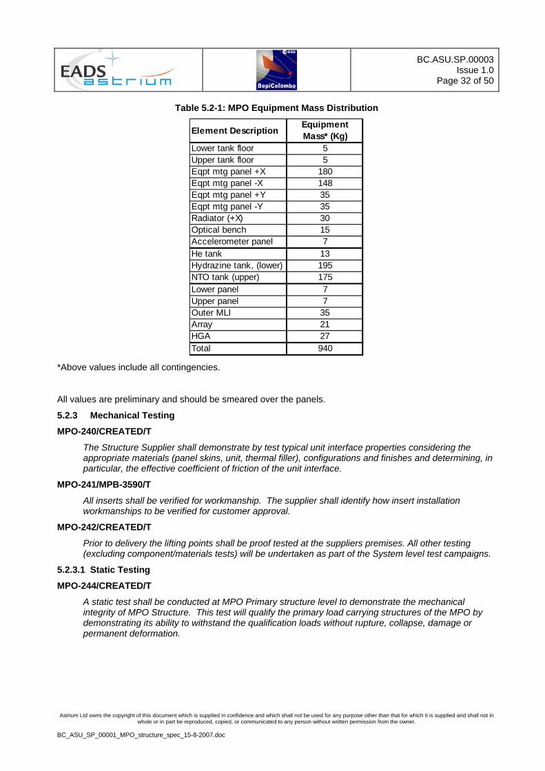
Table 5.2-1: MPO Equipment Mass Distribution
Element DescriptionEquipment Mass* (Kg)
Lower tank floor 5Upper tank floor 5Eqpt mtg panel +X 180Eqpt mtg panel -X 148Eqpt mtg panel +Y 35Eqpt mtg panel -Y 35Radiator (+X) 30Optical bench 15Accelerometer panel 7He tank 13Hydrazine tank, (lower) 195NTO tank (upper) 175Lower panel 7Upper panel 7Outer MLI 35Array 21HGA 27Total 940
*Above values include all contingencies.
All values are preliminary and should be smeared over the panels.
5.2.3 Mechanical Testing
MPO-240/CREATED/T
The Structure Supplier shall demonstrate by test typical unit interface properties considering the appropriate materials (panel skins, unit, thermal filler), configurations and finishes and determining, in particular, the effective coefficient of friction of the unit interface.
MPO-241/MPB-3590/T
All inserts shall be verified for workmanship. The supplier shall identify how insert installation workmanships to be verified for customer approval.
MPO-242/CREATED/T
Prior to delivery the lifting points shall be proof tested at the suppliers premises. All other testing (excluding component/materials tests) will be undertaken as part of the System level test campaigns.
5.2.3.1 Static Testing
MPO-244/CREATED/T
A static test shall be conducted at MPO Primary structure level to demonstrate the mechanical integrity of MPO Structure. This test will qualify the primary load carrying structures of the MPO by demonstrating its ability to withstand the qualification loads without rupture, collapse, damage or permanent deformation.

BC.ASU.SP.00003Issue 1.0
Page 33 of 50
Astrium Ltd owns the copyright of this document which is supplied in confidence and which shall not be used for any purpose other than that for which it is supplied and shall not in whole or in part be reproduced, copied, or communicated to any person without written permission from the owner.
BC_ASU_SP_00001_MPO_structure_spec_15-8-2007.doc
MPO-245/CREATED/T
For static testing, the flight representative MPO Primary Structure (shown in Figure 5.2.1) shall be attached to test adapter via the flight Separation System and subjected to a MPO level static test. The MPO structure subcontractor shall have full technical responsibility for the conductance of this test from the point of view of ensuring MPO structure qualification is achieved.
Figure 5.2.1: MPO Primary Structure definition.
The Loads necessary to fulfil the MPO level static test, described in MPO-245, shall be introduced via jacks attached to the flight separation system at the top of the MPO Primary Structure and also at the tank interfaces via the tank dummies, shown in Figure 5.2.1 as tank geometry.
The test will be performed with representative boundary conditions and shall envelope the flight configuration and load cases. The test article will be mounted in a dedicated test rig capable of introducing representative loads in incremental steps.
As part of the MPO level Static Test, the following will be tested and verified:-
• MPO-248,
• MPO-249,
• MPO-250,
• MPO-251,
• MPO-252,
• MPO-253,
• MPO-254,
• MPO-255.
MPO-248/CREATED/A
The MPO Structure shall provide load introduction points to support static testing without compromising the integrity or stiffness of the structure. The MPO Supplier shall provide all test hardware (load plates, beams etc) needed to guarantee a suitable distribution of loads into the MPO structure.
MPO-249/CREATED/I
The MPO Structure shall be delivered already instrumented with strain gauges.

BC.ASU.SP.00003Issue 1.0
Page 34 of 50
Astrium Ltd owns the copyright of this document which is supplied in confidence and which shall not be used for any purpose other than that for which it is supplied and shall not in whole or in part be reproduced, copied, or communicated to any person without written permission from the owner.
BC_ASU_SP_00001_MPO_structure_spec_15-8-2007.doc
MPO-250/CREATED/A
The locations and orientations of the strain and deflection gauges necessary to record the loads and deflections at the critical positions required to demonstrate structural qualification shall be identified by the supplier.
MPO-251/CREATED/T,A
Structural strength tests shall be performed on all safety critical structures (e.g. the primary load paths and primary load introductions such as lifting points) such that the applied loads envelope the qualification load cases specified.
MPO-252/CREATED/T,A
A dedicated stiffness test shall be conducted to verify MPO Primary Structure without tank dummies (shown in Figure 5.2.2) compliance to the stiffness requirements. The MPO Structure stiffness matrix shall be output from the tests including stiffness and stress loads for loading and un-loading phases.
Figure 5.2.2: MPO Primary Structure definition - without tanks.
MPO-253/CREATED/I
Following each test phase, a detailed inspection shall be conducted to verify that no part of the MPO Structure has been damaged.

BC.ASU.SP.00003Issue 1.0
Page 35 of 50
Astrium Ltd owns the copyright of this document which is supplied in confidence and which shall not be used for any purpose other than that for which it is supplied and shall not in whole or in part be reproduced, copied, or communicated to any person without written permission from the owner.
BC_ASU_SP_00001_MPO_structure_spec_15-8-2007.doc
MPO-254/CREATED/T,A
After the stiffness test, the test results shall be compared to the analysis predictions and any differences greater than 10% shall be explained and justified.
MPO-255/CREATED/T,A
The FE model shall then be correlated to the test results such that the difference between the analysis predictions and test results shall be less than 10%.
5.2.3.2 Proof Testing
MPO-257/CREATED/T
A proof test of all bonded joints on the MPO structure shall be carried out by the supplier.
5.3 Thermal Environment
MPO-259/CREATED/T
The MPO Structure shall be designed to be compatible with a post launch design temperature range of -40°C to +100°C.
MPO-731/CREATED/T,A
The MPO Radiator structure shall be compatible with the existence of localised cold spots to -90°C.
MPO-729/CREATED/T
10 cycles between minimum and maximum temperatures shall be taken into account.
MPO-730/CREATED/T
Qualification factors in addition to these shall be taken into account as defined in the GDIR.
MPO-260/CREATED/T
The MPO interface points to the MOSIF adapter shall be qualified to a minimum qualification temperature of -20°C.
MPO-261/CREATED/T
The performance of adhesively bonded joints shall not be degraded by thermal cycling within the temperature range appropriate to the application as defined in MPO-259, MPO-729 or MPO-731.
MPO-262/CREATED/A
The MPO structure design shall take into account the temperature distributions defined in Table 5.3-1:
• Thermoelastic distortions at critical interfaces shall be determined,
• Thermally induced stresses shall be accommodated by the structure design.
MPO-263/CREATED/A
Structural brackets shall be designed to take into account the extreme temperature cases defined in Table 5.3-1.

BC.ASU.SP.00003Issue 1.0
Page 36 of 50
Astrium Ltd owns the copyright of this document which is supplied in confidence and which shall not be used for any purpose other than that for which it is supplied and shall not in whole or in part be reproduced, copied, or communicated to any person without written permission from the owner.
BC_ASU_SP_00001_MPO_structure_spec_15-8-2007.doc
Table 5.3-1: Structural Design Temperatures
Ground test Min (deg C)
Ground test Max (deg C)
Qual temp post launch Min (deg C)
Qual temp post launch Max (deg C)
(2) (2) (1) (1)General -30 +90 -40 +100 Long Term
Local areas of radiators -80 +90 -90 +100
Long term away from heatpipes
Optical Bench
-30 +60 -40 +70 Long Term
Radiators N/A N/A N/A +150
Short term exposure: Max 2 minutes
Description Comments
Notes:
(1) it is essential that the thermal path from radiator mounted units and heatpipes to the outer surface of the radiator surface is not degraded by the post launch qualification environments (ie no permanent relaxation of bolt preload and no voids in or detachments of any radiator bonded surface)
(2) The structure shall be capable of supporting the specified qualification loads, without degradation or failure, after experiencing the specified ground test environment.

BC.ASU.SP.00003Issue 1.0
Page 37 of 50
Astrium Ltd owns the copyright of this document which is supplied in confidence and which shall not be used for any purpose other than that for which it is supplied and shall not in whole or in part be reproduced, copied, or communicated to any person without written permission from the owner.
BC_ASU_SP_00001_MPO_structure_spec_15-8-2007.doc
6 VERIFICATION
6.1 Verification Matrix
Section will detail verification methods and requirements for various structural components including a verification matrix.
MPO-483/CREATED/T
Structural qualification shall be achieved by static test, or other agreed method.
Table 6.1-1: Verification Matrix
Design Workmanship
Embedded Heatpipe to panel conductivity Analysis and coupon tests Ultrasonic testingHeatpipe panel flatness Design NDTOptical bench Coefficient of Thermal Expansion and in plane thermal conductivity
Analysis and coupon tests-
Optical bench and ISM compatibility with differential expanson Coupon test -Structure Design allowables (Insert strength, bonded joint strength) Coupon test Proof test/ coupon testsStructure load carrying capability Static test of STM primary structure* Proof test of all bonded elementsStructure stiffness Static test of STM primary structure plus
local load application to verify interface stiffnesses of complete structure**
Dynamic testing of flight model at system level by customer
Verification MethodItem
Note * Load application points to be MPO to MOSIF interface and Tank interfaces
** Load application points to be MPO to MOSIF interface and Tank interfaces plus; SADM, HGA and Magnetometer Boom interfaces

BC.ASU.SP.00003Issue 1.0
Page 38 of 50
Astrium Ltd owns the copyright of this document which is supplied in confidence and which shall not be used for any purpose other than that for which it is supplied and shall not in whole or in part be reproduced, copied, or communicated to any person without written permission from the owner.
BC_ASU_SP_00001_MPO_structure_spec_15-8-2007.doc
7 GDIR APPLICABILITY MATRIX
The following table lists the applicable requirements of the GDIR.
It contains, in the first column, the Local ID for each applicable GDIR requirement number.
The second column contains the GDIR Requirement number and the opening text of the requirement.
The third column defines the Applicability Y/N
The final column shows the intended verification method. If no method is shown it shall be assumed that verification is required and the method is TBD
Req No. Reference Applicability Verif. Method
2 Applicable and Reference Documents 2.1 Applicable Documents MPO-762 GDI-3994:
The following documents, of the latest issue, or o ... Y
2.2 Applicable Standards MPO-764 GDI-3993:
The following documents, of the latest issue, or o ... Y
2.2.1 ECSS 2.2.2 Military/Industrial 3 General Design and Interface Requirements 3.1 General Design Requirements 3.1.1 Lifetime MPO-770 GDI-35:
The equipment/subsystem shall meet the requirement ... Y TBD
MPO-771 GDI-38: Maintenance during storage shall be as limited as ...
Y A
MPO-772 GDI-37: The MPO equipment/subsystems shall be designed wit ...
Y A
MPO-773 GDI-51: The MPO equipment/subsystems shall be designed to ...
Y T,A
MPO-774 GDI-47: All MPO consumables shall be sized to allow for th ...
Y T,A
MPO-775 GDI-48: Where the design margin on nominal lifetime is not ...
Y R,TBC
MPO-776 GDI-49: The lifetime of items which degrade shall be desig ...
Y R,TBC
3.1.2 Safety and Product Liability MPO-778 GDI-55:
The subcontractor shall comply to the applicable s ... Y A
MPO-779 GDI-56: The subcontractor shall comply to the applicable p ...
Y A
3.1.4 Venting MPO-781 GDI-65:
Provisions shall be implemented in the design of t ... Y R
MPO-782 GDI-66: The method of venting shall prevent the release of ...
Y R
MPO-783 GDI-59: The equipment/subsystem shall be able to operate w ...
Y A,R
MPO-784 GDI-63: Vents shall be < 5mm diameter and > 1.5mm diameter ...
Y R
MPO-785 GDI-60: For all relevant thermal hardware, explicitly MLI, ...
Y R
MPO-786 GDI-62: Structural members (honeycomb panels, in particula ...
Y R

BC.ASU.SP.00003Issue 1.0
Page 39 of 50
Astrium Ltd owns the copyright of this document which is supplied in confidence and which shall not be used for any purpose other than that for which it is supplied and shall not in whole or in part be reproduced, copied, or communicated to any person without written permission from the owner.
BC_ASU_SP_00001_MPO_structure_spec_15-8-2007.doc
Req No. Reference Applicability Verif. Method
3.1.5 Interchangeability MPO-788 GDI-70:
All spacecraft equipment/subsystems of the same pa ... Y R
3.1.6 Identification & Marking MPO-790 GDI-72:
The equipment hardware shall be identified with a ... Y I
MPO-791 GDI-73: The equipment/subsystem identification nameplate s ...
Y I
MPO-792 GDI-74: For the particular case of connector identificatio ...
Y I
MPO-793 GDI-82: The design of the equipment/subsystem, the positio ...
Y R
MPO-794 GDI-83: The equipment shall be designed to require a minim ...
Y R
MPO-795 GDI-84: No field maintenance, servicing or adjustment shal ...
Y R
MPO-796 GDI-87: Pyro or release mechanism or single shot device in ...
Y R
MPO-797 GDI-3157: Spacecraft subsystems that make use of pyrotechnic ...
Y R
MPO-798 GDI-3152: The design of the spacecraft shall be constrained ...
Y R
MPO-799 GDI-3154: It shall be possible to access or remove equipment ...
Y R
MPO-800 GDI-3155: Items requiring integration, adjustment, servicing ...
Y R
MPO-801 GDI-3156: Items to be removed before flight (red-tag items) ...
Y I
3.1.8 Transportation, Handling and Storage 3.1.8.1 Transport MPO-804 GDI-77:
The equipment/subsystems shall be transported usin ... Y R
MPO-805 GDI-78: The equipment/subsystem containers, covers (for op ...
Y R
MPO-806 GDI-79: The equipment/subsystem transport container shall ...
Y R
MPO-807 GDI-80: The equipment/subsystem storage container shall be ...
Y R
3.1.8.2 Equipment/Subsystem Packing MPO-809 GDI-90:
Where applicable blanking caps shall be fitted to ... Y I
MPO-810 GDI-91: All equipment shall be packaged to ensure that it ...
Y I
MPO-811 GDI-93: The specified item GSE shall follow as far as appr ...
Y I
3.1.8.3 Container Identification MPO-813 GDI-95:
Each container shall be labelled, tagged or marked ... Y I
MPO-814 GDI-96: In addition to the above, the container shall also ...
Y I
MPO-815 GDI-2267: Size of company labels on containers shall be agre ...
Y R
3.1.8.4 Handling

BC.ASU.SP.00003Issue 1.0
Page 40 of 50
Astrium Ltd owns the copyright of this document which is supplied in confidence and which shall not be used for any purpose other than that for which it is supplied and shall not in whole or in part be reproduced, copied, or communicated to any person without written permission from the owner.
BC_ASU_SP_00001_MPO_structure_spec_15-8-2007.doc
Req No. Reference Applicability Verif. Method
MPO-817 GDI-98: Equipment/subsystem weighing more than 10 kg shall ...
Y R
3.1.9 Seals MPO-819 GDI-100:
Any seals used shall comply with all the applicabl ... Y R
MPO-820 GDI-101: Any seals requiring periodic replacement during gr ...
Y R
3.1.10 Lubricants and Sealants MPO-822 GDI-103:
No lubricants or sealants shall be used without th ... Y R
3.1.13 Contamination Sensitive Items MPO-824 GDI-3969:
For items known to be sensitive to contamination s ... Y R
MPO-825 GDI-3970: implementation of protective covers which can be e ...
Y R
MPO-826 GDI-3971: implementation of purge port allowing the connecti ...
Y R
3.2 Mechanical Design and Interface Requirements MPO-828 GDI-105:
All drawings, specifications and engineering data ... Y R
MPO-829 GDI-106: Equipment/subsystem shall be compatible with mecha ...
Y R
MPO-830 GDI-2137: Material selection shall be in accordance with ECS ...
Y R
MPO-831 GDI-2139: Mechanical parts selection shall be in accordance ...
Y R
3.2.1 Coordinate System 3.2.1.1 General MPO-834 GDI-3980:
All reference frames shall be right-handed orthogo ... Y R
3.2.1.2 MCS Physical Reference Frame MPO-836 GDI-3982:
The MCS coordinate system shall be as defined in F ... Y R
3.2.1.3 MPO Physical Reference Frame MPO-838 GDI-3986:
The MPO coordinate system shall be as defined in F ... Y R
3.2.2 Structural Design 3.2.2.1 General Requirements MPO-841 GDI-117:
The following failure modes, for equipment/subsyst ... Y A
MPO-842 GDI-118: For all structural items the following analyses ar ...
Y A
MPO-843 GDI-119: Dynamic Analysis: The dynamic analysis shall show ...
Y A
MPO-844 GDI-120: Static Analysis: The analysis shall identify and r ...
Y A
MPO-845 GDI-121: Stress Analysis: For each item a complete stress/s ...
Y A
MPO-846 GDI-122: No yielding is allowed at proof load/proof pressur ...
Y T
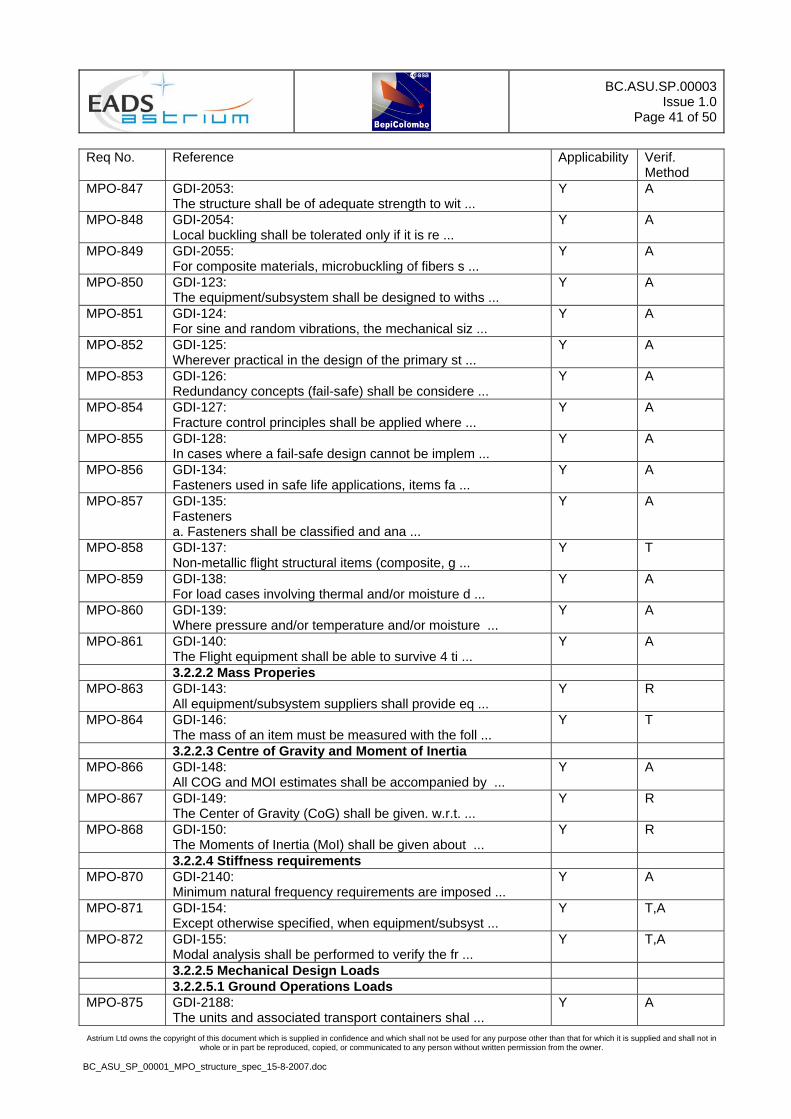
BC.ASU.SP.00003Issue 1.0
Page 41 of 50
Astrium Ltd owns the copyright of this document which is supplied in confidence and which shall not be used for any purpose other than that for which it is supplied and shall not in whole or in part be reproduced, copied, or communicated to any person without written permission from the owner.
BC_ASU_SP_00001_MPO_structure_spec_15-8-2007.doc
Req No. Reference Applicability Verif. Method
MPO-847 GDI-2053: The structure shall be of adequate strength to wit ...
Y A
MPO-848 GDI-2054: Local buckling shall be tolerated only if it is re ...
Y A
MPO-849 GDI-2055: For composite materials, microbuckling of fibers s ...
Y A
MPO-850 GDI-123: The equipment/subsystem shall be designed to withs ...
Y A
MPO-851 GDI-124: For sine and random vibrations, the mechanical siz ...
Y A
MPO-852 GDI-125: Wherever practical in the design of the primary st ...
Y A
MPO-853 GDI-126: Redundancy concepts (fail-safe) shall be considere ...
Y A
MPO-854 GDI-127: Fracture control principles shall be applied where ...
Y A
MPO-855 GDI-128: In cases where a fail-safe design cannot be implem ...
Y A
MPO-856 GDI-134: Fasteners used in safe life applications, items fa ...
Y A
MPO-857 GDI-135: Fasteners a. Fasteners shall be classified and ana ...
Y A
MPO-858 GDI-137: Non-metallic flight structural items (composite, g ...
Y T
MPO-859 GDI-138: For load cases involving thermal and/or moisture d ...
Y A
MPO-860 GDI-139: Where pressure and/or temperature and/or moisture ...
Y A
MPO-861 GDI-140: The Flight equipment shall be able to survive 4 ti ...
Y A
3.2.2.2 Mass Properies MPO-863 GDI-143:
All equipment/subsystem suppliers shall provide eq ... Y R
MPO-864 GDI-146: The mass of an item must be measured with the foll ...
Y T
3.2.2.3 Centre of Gravity and Moment of Inertia MPO-866 GDI-148:
All COG and MOI estimates shall be accompanied by ... Y A
MPO-867 GDI-149: The Center of Gravity (CoG) shall be given. w.r.t. ...
Y R
MPO-868 GDI-150: The Moments of Inertia (MoI) shall be given about ...
Y R
3.2.2.4 Stiffness requirements MPO-870 GDI-2140:
Minimum natural frequency requirements are imposed ... Y A
MPO-871 GDI-154: Except otherwise specified, when equipment/subsyst ...
Y T,A
MPO-872 GDI-155: Modal analysis shall be performed to verify the fr ...
Y T,A
3.2.2.5 Mechanical Design Loads 3.2.2.5.1 Ground Operations Loads MPO-875 GDI-2188:
The units and associated transport containers shal ... Y A

BC.ASU.SP.00003Issue 1.0
Page 42 of 50
Astrium Ltd owns the copyright of this document which is supplied in confidence and which shall not be used for any purpose other than that for which it is supplied and shall not in whole or in part be reproduced, copied, or communicated to any person without written permission from the owner.
BC_ASU_SP_00001_MPO_structure_spec_15-8-2007.doc
Req No. Reference Applicability Verif. Method
MPO-876 GDI-2189: Vertical and horizontal loads shall be considered ...
Y A
MPO-877 GDI-2199: The transportation containers shall be designed to ...
Y A
MPO-878 GDI-2200: The MGSE design and analysis shall consider a desi ...
Y A
MPO-879 GDI-3629: During ground transportation the units shall withs ...
Y A
MPO-880 GDI-3664: All MGSE, containers, transportation and handling ...
Y A
MPO-881 GDI-3665: Sine and random vibrations: the unit transport con ...
Y A
3.2.2.5.2 Launch and Early Orbit Phase. 3.2.2.5.2.1 Unit Quasi-Static Loads MPO-884 GDI-3670:
The quasi-static and low frequency flight limit ac ... Y A
MPO-885 GDI-3671: The loads shall be applied at the unit CoG in out- ...
Y A
3.2.2.6 Strength requirements 3.2.2.6.1 Definitions and General Requirements MPO-888 GDI-3612:
The design load factor philosophy of the unit shal ... Y A
MPO-889 GDI-3614: The Flight or Ground Limit Load, LL, is the load t ...
Y A
MPO-890 GDI-3615: Qualification Load, QL is equal to the Limit Load ...
Y A
MPO-891 GDI-3616: Design Load, DL is derived by the multiplication o ...
Y A
MPO-892 GDI-3617: Yield Load, YL is derived by the multiplication of ...
Y A
MPO-893 GDI-3618: Ultimate Load, UL is derived by the multiplication ...
Y A
MPO-894 GDI-3619: Yield Factor of Safety, FOSY ensures that unaccept ...
Y A
MPO-895 GDI-3620: Ultimate Factor of Safety, FOSU ensures that unacc ...
Y A
MPO-896 GDI-3621: Additional Factor of Safety, KADD are additional f ...
Y A
MPO-897 GDI-3622: Unit mechanical testing shall take into account an ...
Y A
MPO-898 GDI-3623: An additional Protoflight Factor of Safety, FOSPF ...
Y A
3.2.2.6.2 Margins of Safety and Factors of Safety MPO-900 GDI-186:
An uncertainty factor Jf shall be defined to provi ... Y A
MPO-901 GDI-187: A Qualification Factor of 1.5 shall be used for KQ ...
Y T
MPO-902 GDI-188: An Acceptance Factor of 1.0 shall be used for KA t ...
Y A
MPO-903 GDI-189: A Design Factor of 1.5 shall be used for DF to det ...
Y A
MPO-904 GDI-194: The unit shall be able to withstand, without failu ...
Y A

BC.ASU.SP.00003Issue 1.0
Page 43 of 50
Astrium Ltd owns the copyright of this document which is supplied in confidence and which shall not be used for any purpose other than that for which it is supplied and shall not in whole or in part be reproduced, copied, or communicated to any person without written permission from the owner.
BC_ASU_SP_00001_MPO_structure_spec_15-8-2007.doc
Req No. Reference Applicability Verif. Method
MPO-905 GDI-195: Margin of safety (MOS) a. Margins of safety (MOS) ...
Y A
MPO-906 GDI-198: For combined loads where L(P) is the load due to m ...
Y A
MPO-907 GDI-3229: Table [SRD-3782]: Minimum Factors of Safety ...
Y A
MPO-908 GDI-207: Conservative friction coefficients regarding minim ...
Y A
MPO-909 GDI-208: Wherever applicable, for general design of bolts, ...
Y R
MPO-910 GDI-209: In addition, in case of combined loads due to ther ...
Y A
MPO-911 GDI-3398: The design loads for the structure elements are t ...
Y A
MPO-912 GDI-3400: The internal loads (thermo elastic, pre-stressed ...
Y A
MPO-913 GDI-3401: For sine and random vibrations, the mechanical siz ...
Y A
MPO-914 GDI-3402: The margins of safety for all elements of the unit ...
Y A
3.2.3 Design Requirements 3.2.3.1 Mounting Requirements MPO-917 GDI-219:
The attachment points of the equipment/subsystem s ... Y R
MPO-918 GDI-3995: The attachment points shall provide a controlled s ...
Y I,R
MPO-919 GDI-3996: The mechanical mounting interface shall be consist ...
Y R
MPO-920 GDI-220: The number of attachement bolts for a equipment sh ...
Y A
MPO-921 GDI-221: The interface plane flatness of a equipment/subsys ...
Y I
MPO-922 GDI-222: The equipment/subsystem bolts type and number shal ...
Y R
MPO-923 GDI-223: Except otherwise specified, all equipment/subsyste ...
Y R
MPO-924 GDI-228: Unless special conditions override, the thickness ...
Y R
MPO-925 GDI-229: Minimum clearance between mechanical parts shall c ...
Y R
MPO-926 GDI-230: All equipment/subsystems shall be designed allowin ...
Y A
MPO-927 GDI-2550: The minimum load carrying capability of the insert ...
Y A,R
MPO-928 GDI-2551: The following typical insert distances along the m ...
Y A,R
3.2.3.2 Alignment Requirements MPO-930 GDI-232:
Equipment/subsystems requiring alignment with an a ... Y R
MPO-931 GDI-233: Optical references are required to withstand all t ...
Y R

BC.ASU.SP.00003Issue 1.0
Page 44 of 50
Astrium Ltd owns the copyright of this document which is supplied in confidence and which shall not be used for any purpose other than that for which it is supplied and shall not in whole or in part be reproduced, copied, or communicated to any person without written permission from the owner.
BC_ASU_SP_00001_MPO_structure_spec_15-8-2007.doc
Req No. Reference Applicability Verif. Method
MPO-932 GDI-234: Location of optical references for equipment/subsy ...
Y R
MPO-933 GDI-235: The alignment errors shall be included in pointing ...
Y R
MPO-934 GDI-236: Equipment/subsystems which require alignment accur ...
Y R
3.2.4 Mechanical / Optical Interface Control Documents MPO-936 GDI-239:
The mechanical and optical configuration and its i ... Y A
MPO-937 GDI-240: Interfaces will be subjected to a formal inspectio ...
Y T,I
MPO-938 GDI-241: The issues of ICDs have to be released as defined ...
Y A
MPO-939 GDI-244: The equipment/subsystem alignment reference frame ...
Y R
MPO-940 GDI-246: The dimensioning of the attachment hole pattern sh ...
Y A
MPO-941 GDI-247: Interface Control Drawings shall be provided to AS ...
Y R
3.2.5 Mechanical Mathematical Model Requirements MPO-943 GDI-253:
Detailed Finite Element Models (FEM) shall be prov ... Y A
MPO-944 GDI-3830: Detailed Finite Element Models (FEM) shall be prov ...
Y A
MPO-945 GDI-254: All FE model requirements, checks and formats are ...
Y T
3.2.5.1 Allocation of Node Ranges for External Models MPO-947 GDI-2534:
The table below specifies the node ranges applicab ... Y R
3.4 Thermal Design and Interface Requirements 3.4.1 Definitions MPO-950 GDI-3179:
Chapter 3 of ECSS-E-30 Part 1 shall apply with the ... Y A
3.4.2 Definition of Temperatures and Terms 3.4.2.4 Temperature Reference Point (TRP) MPO-953 GDI-307:
The temperature reference point (TRP) shall be sel ... Y R
3.4.2.5 System Interface Temperature Point (STP) MPO-955 GDI-3876:
The system interface temperature point (STP) if de ... Y T,A
MPO-956 GDI-3882: The equipment/unit supplier shall analyse the heat ...
Y A
MPO-957 GDI-3877: Items mounted on the optical bench shall be cooled ...
Y R
3.4.3 Thermal Interface Requirements 3.4.3.1 Conductive Interface MPO-960 GDI-316:
The mounting interface shall comply with the mecha ... Y A
MPO-961 GDI-317: Equipment/subsystem mounting areas shall not be pa ...
Y R
MPO-962 GDI-318: All equipment/subsystems shall have a smooth and p ...
Y R
MPO-963 GDI-319: Local heat flux shall not be greater than 1.5x spe ...
Y A

BC.ASU.SP.00003Issue 1.0
Page 45 of 50
Astrium Ltd owns the copyright of this document which is supplied in confidence and which shall not be used for any purpose other than that for which it is supplied and shall not in whole or in part be reproduced, copied, or communicated to any person without written permission from the owner.
BC_ASU_SP_00001_MPO_structure_spec_15-8-2007.doc
Req No. Reference Applicability Verif. Method
MPO-964 GDI-2536: An interface filler with a coefficient of friction ...
Y R
3.4.3.2 Radiative Interface MPO-966 GDI-322:
Equipment/subsystems shall be designed with an emi ... Y R
3.4.3.3 Internal Temperature Monitoring MPO-968 GDI-324:
Temperature monitoring of selected points within a ... Y R
MPO-969 GDI-325: The location, type and electrical interface of all ...
Y R
3.4.4 Thermal Design Requirements MPO-971 GDI-3184:
Dimensioning of the Thermal Control of space expos ... Y A
MPO-972 GDI-3881: Dimensioning of the standard Equipment/UnitThermal ...
Y A
MPO-973 GDI-327: The equipment/subsystems shall be designed such th ...
Y A
MPO-974 GDI-3188: Use of materials with non-stable thermo-optical pr ...
Y T,R
MPO-975 GDI-3193: It shall be possible to demonstrate conformance of ...
Y T,A
3.4.5 Thermal Control MPO-977 GDI-331:
All thermal hardware mounted on the equipment/subs ... Y R
3.4.6 Thermal Interface Control Documents MPO-979 GDI-333:
All equipment/subsystem thermal interfaces shall b ... Y R
3.4.7 Thermal Mathematical Model Requirements MPO-981 GDI-3201:
The compliance to the thermal performance requirem ... Y A
MPO-982 GDI-3202: In case of TB test execution, the temperature unce ...
Y A
3.4.7.2 Thermal Interface Modeling MPO-984 GDI-336:
The Thermal mathematical model shall be provided f ... Y A
MPO-985 GDI-337: SI units: All units used in thermal models (geomet ...
Y A
3.4.7.3 Thermal Model Correlation MPO-987 GDI-339:
The detailed thermal model of a equipment/subsyste ... Y T,A
3.4.7.4 Reduced Thermal Model MPO-989 GDI-341:
The consistency between reduced and detailed therm ... Y A
MPO-990 GDI-342: The convergence of the thermal models shall be dem ...
Y A
4 Unit/Equipment/Subsystem Level Environment Test Requirements
5 Appendix A : MICD 5.1 Mechanical Interface Datasheet MPO-994 GDI-2760:
The mechanical and optical configuration and its i ... Y R

BC.ASU.SP.00003Issue 1.0
Page 46 of 50
Astrium Ltd owns the copyright of this document which is supplied in confidence and which shall not be used for any purpose other than that for which it is supplied and shall not in whole or in part be reproduced, copied, or communicated to any person without written permission from the owner.
BC_ASU_SP_00001_MPO_structure_spec_15-8-2007.doc
8 ANNEXES
8.1 Additional Drawings and Information
Figure 8.1.1: MPO Separation Interface configuration.

BC.ASU.SP.00003
Issue 1.0Page 47 of 50
Document Autogenerated from DOORS Module : /BepiColombo Implementation Phase/Level 3 Equipment Specifications/MPB/MPO Structure Specification BC_ASU_SP_00001_MPO_structure_spec_15-8-2007.doc
Figure 8.1.2: MPO Structure Geometry (1).

BC.ASU.SP.00003Issue 1.0
Page 48 of 50
Astrium Ltd owns the copyright of this document which is supplied in confidence and which shall not be used for any purpose other than that for which it is supplied and shall not in whole or in part be reproduced, copied, or communicated to any person without written permission from the owner.
BC_ASU_SP_00001_MPO_structure_spec_15-8-2007.doc
Figure 8.1.3: MPO Structure Geometry (2).

BC.ASU.SP.00003Issue 1.0
Page 49 of 50
Astrium Ltd owns the copyright of this document which is supplied in confidence and which shall not be used for any purpose other than that for which it is supplied and shall not in whole or in part be reproduced, copied, or communicated to any person without written permission from the owner.
BC_ASU_SP_00001_MPO_structure_spec_15-8-2007.doc
Requirement/Section Cross Reference Page numbers are the pages where the sections start
MPO-74 .............. 3.1....................7 MPO-81 .............. 3.1.2.................8 MPO-82 .............. 3.1.2.................8 MPO-91 .............. 3.1.4.................9 MPO-92 .............. 3.1.4.................9 MPO-94 .............. 3.1.4.................9 MPO-95 .............. 3.1.4.................9 MPO-96 .............. 3.1.4.................9 MPO-97 .............. 3.1.4.................9 MPO-99 .............. 3.1.4.................9 MPO-100 ............ 3.1.4.................9 MPO-101 ............ 3.1.4.................9 MPO-103 ............ 3.1.4.................9 MPO-104 ............ 3.1.4.................9 MPO-105 ............ 3.1.4.................9 MPO-106 ............ 3.1.4.................9 MPO-107 ............ 3.1.4.................9 MPO-109 ............ 3.1.4.................9 MPO-110 ............ 3.1.4.................9 MPO-111 ............ 3.1.4.................9 MPO-113 ............ 3.1.5.................14 MPO-115 ............ 3.1.5.................14 MPO-119 ............ 3.2.1.................15 MPO-120 ............ 3.2.1.................15 MPO-121 ............ 3.2.1.................15 MPO-122 ............ 3.2.1.................15 MPO-123 ............ 3.2.1.................15 MPO-124 ............ 3.2.1.................15 MPO-127 ............ 3.3.1.................15 MPO-128 ............ 3.3.1.................15 MPO-129 ............ 3.3.1.................15 MPO-131 ............ 3.3.2.................16 MPO-134 ............ 3.3.2.................16 MPO-135 ............ 3.3.2.................16 MPO-138 ............ 3.4....................17 MPO-139 ............ 3.4....................17 MPO-140 ............ 3.4....................17 MPO-141 ............ 3.4....................17 MPO-142 ............ 3.4....................17 MPO-143 ............ 3.4....................17 MPO-145 ............ 3.5....................18 MPO-146 ............ 3.5....................18 MPO-147 ............ 3.5....................18 MPO-148 ............ 3.5....................18 MPO-150 ............ 3.5....................18 MPO-152 ............ 3.5....................18 MPO-153 ............ 3.5....................18 MPO-154 ............ 3.5....................18 MPO-155 ............ 3.5....................18 MPO-156 ............ 3.5....................18 MPO-157 ............ 3.5....................18 MPO-158 ............ 3.5....................18 MPO-159 ............ 3.5....................18 MPO-160 ............ 3.5....................18 MPO-161 ............ 3.5....................18 MPO-162 ............ 3.5....................18 MPO-163 ............ 3.5....................18
MPO-167.............4.1 ................... 24 MPO-170.............4.2.1 ................ 24 MPO-171.............4.2.1 ................ 24 MPO-173.............4.2.2 ................ 24 MPO-175.............4.2.3 ................ 24 MPO-178.............4.2.4.1 ............. 24 MPO-180.............4.2.4.2 ............. 25 MPO-182.............4.2.5 ................ 25 MPO-183.............4.2.5 ................ 25 MPO-186.............4.3.1 ................ 25 MPO-187.............4.3.1 ................ 25 MPO-188.............4.3.1 ................ 25 MPO-189.............4.3.1 ................ 25 MPO-192.............4.3.1 ................ 25 MPO-196.............4.3.1 ................ 25 MPO-197.............4.3.1 ................ 25 MPO-198.............4.3.1 ................ 25 MPO-199.............4.3.1 ................ 25 MPO-202.............4.3.1 ................ 25 MPO-203.............4.3.1 ................ 25 MPO-204.............4.3.1 ................ 25 MPO-205.............4.3.1 ................ 25 MPO-206.............4.3.1 ................ 25 MPO-207.............4.3.1 ................ 25 MPO-208.............4.3.1 ................ 25 MPO-209.............4.3.1 ................ 25 MPO-210.............4.3.1 ................ 25 MPO-213.............4.3.2.1 ............. 29 MPO-214.............4.3.2.1 ............. 29 MPO-215.............4.3.2.1 ............. 29 MPO-216.............4.3.2.1 ............. 29 MPO-217.............4.3.2.1 ............. 29 MPO-219.............4.3.3 ................ 30 MPO-220.............4.3.3 ................ 30 MPO-221.............4.3.3 ................ 30 MPO-225.............5.1.1 ................ 31 MPO-227.............5.2 ................... 31 MPO-228.............5.2 ................... 31 MPO-230.............5.2.1 ................ 31 MPO-231.............5.2.1 ................ 31 MPO-233.............5.2.1 ................ 31 MPO-236.............5.2.1 ................ 31 MPO-238.............5.2.2 ................ 31 MPO-240.............5.2.3 ................ 32 MPO-241.............5.2.3 ................ 32 MPO-242.............5.2.3 ................ 32 MPO-244.............5.2.3.1 ............. 32 MPO-245.............5.2.3.1 ............. 32 MPO-248.............5.2.3.1 ............. 32 MPO-249.............5.2.3.1 ............. 32 MPO-250.............5.2.3.1 ............. 32 MPO-251.............5.2.3.1 ............. 32 MPO-252.............5.2.3.1 ............. 32 MPO-253.............5.2.3.1 ............. 32 MPO-254.............5.2.3.1 ............. 32 MPO-255.............5.2.3.1 ............. 32 MPO-257.............5.2.3.2 ............. 35
MPO-259 ............ 5.3 ....................35 MPO-260 ............ 5.3 ....................35 MPO-261 ............ 5.3 ....................35 MPO-262 ............ 5.3 ....................35 MPO-263 ............ 5.3 ....................35 MPO-477 ............ 3.3.2 .................16 MPO-479 ............ 3.3.2 .................16 MPO-480 ............ 3.3.2 .................16 MPO-483 ............ 6.1 ....................37 MPO-723 ............ 3.1.4 .................9 MPO-724 ............ 3.1.4 .................9 MPO-725 ............ 4.3.1 .................25 MPO-726 ............ 3.1.4 .................9 MPO-729 ............ 5.3 ....................35 MPO-730 ............ 5.3 ....................35 MPO-731 ............ 5.3 ....................35 MPO-732 ............ 4.3.2.1 ..............29 MPO-733 ............ 3.2.1 .................15 MPO-734 ............ 3.3.2 .................16 MPO-736 ............ 3.3.2 .................16 MPO-738 ............ 3.3.2 .................16 MPO-746 ............ 4.3.2.1 ..............29 MPO-748 ............ 3.6 ....................21 MPO-749 ............ 3.6 ....................21 MPO-750 ............ 3.6 ....................21 MPO-755 ............ 3.3.2 .................16 MPO-995 ............ 3.1.4 .................9 MPO-997 ............ 4.2.2 .................24 MPO-998 ............ 4.2.2 .................24 MPO-1000 .......... 4.3.1 .................25 MPO-1001 .......... 4.3.1 .................25 MPO-1004 .......... 3.1.4 .................9 MPO-1005 .......... 3.3.2 .................16 MPO-1006 .......... 3.3.2 .................16 MPO-1007 .......... 3.6 ....................21 MPO-1008 .......... 3.3.2 .................16 MPO-1022 .......... 4.2.4.2 ..............25 MPO-1036 .......... 3.7.1 .................22 MPO-1037 .......... 3.7.1 .................22 MPO-1038 .......... 3.7.1 .................22 MPO-1042 .......... 3.7.2 .................23 MPO-1043 .......... 3.7.2 .................23 MPO-1046 .......... 3.7.3 .................23 MPO-1054 .......... 3.7.4 .................23 MPO-1056 .......... 3.7.5 .................23 MPO-1057 .......... 3.1.4 .................9 MPO-1063 .......... 3.2.2 .................15 MPO-1064 .......... 3.2.2 .................15 MPO-1071 .......... 3.3.2 .................16 MPO-1072 .......... 4.3.1 .................25

BC.ASU.SP.00003Issue 1.0
Page 50 of 50
Astrium Ltd owns the copyright of this document which is supplied in confidence and which shall not be used for any purpose other than that for which it is supplied and shall not in whole or in part be reproduced, copied, or communicated to any person without written permission from the owner.
BC_ASU_SP_00001_MPO_structure_spec_15-8-2007.doc
DOCUMENT CHANGE DETAILS
ISSUE CHANGE AUTHORITY CLASS RELEVANT INFORMATION/INSTRUCTIONS 1.0 - Initial Issue.
DISTRIBUTION LIST
INTERNAL EXTERNAL