Embed Size (px)
Citation preview

1 Copyright © 2012 by ASME
Proceedings of ASME Turbo Expo 2012 GT2012
June 11-15, 2012, Copenhagen, Denmark
GT2012-69065
DEVELOPMENT OF A ROBUST STRUCTURAL HEALTH MONITORING SYSTEM FOR WIND TURBINE FOUNDATIONS
Magnus Currie
EPSRC Wind Energy DTC Department of EEE
University of Strathclyde, Glasgow, Scotland, G1 1XW [email protected]
Dr Mohamed Saafi
Department of Civil Engineering University of Strathclyde
Glasgow, Scotland, G1 1XW [email protected]
Dr Francis Quail
Dept. of Electrical Engineering University of Strathclyde
Glasgow, Scotland, G1 1XW [email protected]
ABSTRACT The construction of onshore wind turbines has rapidly been
increasing as the UK attempts to meet its renewable energy
targets. As the UK’s future energy depends more on wind
farms, safety and security are critical to the success of this
renewable energy source. Structural integrity is a critical
element of this security of supply. With the stochastic nature
of the load regime a bespoke low cost structural health
monitoring system is required to monitor integrity. This paper
presents an assessment of ‘embedded can’ style foundation
failure modes in large onshore wind turbines and proposes a
novel condition based monitoring solution to aid in early
warning of failure.
INTRODUCTION Large scale development of onshore wind turbines as part of a
strategy to meet UK government targets has been a result of the
Governments obligations to reach European Union carbon
reduction targets. Increasing the percentage of renewable
energy in the electricity mix, displacing older, fossil fuelled,
thermal generation will result in wind energy becoming an
important component. The United Kingdom has a target to
produce 15% of its energy needs through renewable methods
by the year 2020 [1]. In order to meet this ambitious target
numerous wind farms have been constructed recently and
others are under construction or in planning phases. Ensuring
reliability of wind turbine structures allows safe operation and
maximum availability.
Wind turbines operate under challenging loading regimes [2]
the effects of which could diminish their structural integrity
leading to significant remediation costs and disruption to the
electrical grid. Current research activities focus on for example
structural damage of blades [3]. Structural health monitoring
(SHM) provides the means to track the structural condition of
turbines throughout their 20-25 year lifecycle [3]. Protecting
assets and maximizing power production are challenges and
priorities for wind turbine operators.
Over time, the onshore turbine structure will become less
efficient and less effective when compared with a new one.
This can be caused by numerous factors including
environmental exposure, fatigue of blades, tower and concrete
foundation, soil settlement, poor construction and poor
maintenance. Health and condition monitoring systems are
often used on components such as the gearbox but are used less
frequently to monitor the state of structural components [4].
There are three main areas where SHM can be applied to an
onshore wind turbine: the rotor (including the blades), the
tower and the foundation. Each structural component presents
different structural problems, failure modes and failure rates.
This paper considers some technical challenges including
structural behavior/failure modes of onshore wind turbines and
affect on wind turbine foundations. Current health monitoring
technologies with potential applications to onshore wind
turbines are considered and a novel health monitoring strategy
for the wind turbine’s foundation with continuous proactive
capability is presented. The paper also presents some key
research themes to develop a robust SHM technology.
Structural failure rates and an analysis of foundation failure
modes are presented. The outcome of a field visit to a wind
farm site exhibiting signs of failure is then covered. Finally a
novel structural health monitoring system is proposed to
continuously monitor the level of failure in the foundation.

2 Copyright © 2012 by ASME
1. STRUCTURAL DAMAGE IN ONSHORE WIND TURBINES Figure 1 shows a usual arrangement of an onshore wind
turbine, with blades, tower and gravity concrete foundation.
Main types of foundation-tower interface used for large onshore
turbines are the ‘embedded can’ and the ‘bolted’.
Figure 1: MAIN STRUCTURAL COMPONENTS OF A TURBINE
Current research is focused on structural damage of blades
and towers; specific information on the structural behavior of
wind turbine foundations however is very limited, in particular
there is a lack of in-depth reporting of failures. Tavner et al [5]
provides a useful guide to the levels of component structural
failure within turbines in several countries. The work shows
the blade failure rate including pitch mechanism is between 0.2
and 1.0 per turbine per year, although the average is closer to
0.2. The actual blade failure rate (not including the pitch
mechanism) is much lower reaching 0.025 failures per turbine
per year as calculated in [6]. A survey effort of more than 1500
offshore wind turbines conducted by the European Wind
Energy Measurement and Evaluation Program (WMEP)
showed that the blade failure rate is around 0.11 per turbine per
year whereas the failure rate of support and housing is about
0.1 failures per turbine per year [7]. The same survey shows
that the rate of failure of the nacelle is 0.003 failures per year
per turbine and the tower failure is around 0.001. Based on the
literature review it was found that the average turbine is
extremely unlikely to suffer failure of the tower or the nacelle.
However, the chance that of one of the blades could fail during
its lifecycle is around 50%. The fragility of the blades and risk
of failure is demonstrated by the large amount of research work
in that area compared to articles concerning the turbine tower
and foundation.
2. DAMAGE MECHANISMS AND FAILURE MODES OF WIND TURBINE FOUNDATIONS It is unknown how reliable wind turbine foundations are as
there is a lack of published data available. Whilst a complete
collapse of a turbine is rare, non-catastrophic localized failure
of the reinforced concrete elements of foundations appears to
be more frequent. Recent studies showed that the structural
failures in the tower and foundation account for only a very
small percentage of the total number of failures accounting for
1.5% of failures and 1.2% of downtime [8]. Wind turbine
foundations are normally subjected to large cyclic moments and
forces and if designed incorrectly this could produce structural
damage in the foundation and jeopardize the stability of the
wind turbine. Problems in the foundation can manifest
themselves in a number of ways including deterioration of the
underlying fill and ground below the foundation or in the
degradation of the reinforced concrete pedestal and base. Long-term cyclic loading causes the foundation-soil interface
to degrade resulting in a reduced rotational stiffness which in
return decreases the bearing capacity of the soil. In this case,
gravity foundations exhibit large differential movement and can
tilt under a high lateral wind load as witnessed by the
catastrophic failure of a wind turbine concrete foundation
during a heavy storm in Goldenstedt, Nortwestern Germany in
2002 where it appears the eccentric load severally damaged the
soil subgrade causing the turbine to overturn (see Figure 2).
Figure 2: GOLDENSTEDT WIND TURBINE COLLAPSE
Figure 3 shows the area where voids can develop in a
concrete foundation for embedded can type connections when
the turbine is subjected to eccentric and cyclic loading. Water
ingress through the damaged concrete-web interface coupled
with the movement of the tower can interface acts to exacerbate
the level of movement through erosion. The presence of voids
around the embedded can allows the whole tower to move
significantly in the vertical direction as well as to a smaller
extent in the horizontal direction. There has been no published
work relating to this type of displacement but movements in the

3 Copyright © 2012 by ASME
range of 5mm were noted during a site visit with reports of
movement up to 20mm on other turbines at the same site.
Figure 3: FAILURE MODES (EMBEDDED CAN)
3. FOUNDATION STRUCTURAL HEALTH MONITORING A novel sensing solution is proposed to monitor the state of
large scale multi-MW wind turbine foundations. The system
has been designed for ‘embedded can’ style foundations. The
only data currently gathered on the tower movement is based
upon accelerometer readings from the nacelle. This data does
not give specific details on the foundation. It is unknown how
widespread the problems are due a lack of published data
relating to wind turbine foundations. As existing embedded
can foundations will be in operation for the next 20 – 25 years a
suitable monitoring system is desirable. The machines
involved in the study were Vestas V80 2.0MW [9] turbines
constructed in the last 10 years. During a site visit eight
different turbines were inspected. The turbines showed varying
degrees of movement. A further turbine was inspected which
had undergone remedial work. Figure 4 displays the general
layout of a turbine on site.
Figure 4: EMBEDDED CAN, TOWER AND FOUNDATION
The top section of the foundation is completely buried under
back fill. The embedded can sits around 30mm above the top
of the pedestal and is joined internally to the lower tower
section. Due to this construction technique, any movement of
the can results in an equivalent movement of the tower and
nacelle structure above.
4. EMBEDDED CAN FAILURE MODES The failure of the embedded can is complex and has several
different possible failure modes which may act as one or
together over time to accelerate the failure of the foundation.
The general layout of an embedded can foundation from the
site in question is shown in Figure 5.
Figure 5: EMBEDDED CAN ELEVATION
The steel can is highlighted and has a diameter of 4m. The
foundation has a total diameter of 15m at its base. During
construction the steel can is sited and concrete is then poured
around to complete the upper part of the foundation. Failure of
each foundation is not identical and some may fail at varying
rates, as was witnessed during the site visit. The general order
of events is listed below:
1. Small movements of the tower are possible due to the low
level of friction between the painted can and the concrete. As
the tower moves during operation the green plasticized
waterproof membrane eventually cracks. Cracking occurs
principally around the area between the pedestal and the
penetrating steel can. This is shown in Figure 6.
Figure 6: WATERPROOF MEMBRANE CRACKING
Area where voids develop
4 Copyright © 2012 by ASME
There was no evidence that cracking was only occurring in a
uniform manner. Some turbines had only small single cracks
whereas others have cracks extending to around 2m around the
circumference of the foundation/tower connection. This is
illustrated in Figure 7.
Figure 7: WATERPROOFING DETERIORATION
2. With the waterproof membrane cracked, water is able to
penetrate the foundation, migrating down the gap between the
steel can and the concrete. Water migrates between pores
within the concrete as well as finding pathways along
construction joints. However, with the waterproofing breached
much greater volumes of water can penetrate the entire way
around the foundation even if there is only cracking at one
location. During the site visit it was noted that the water
ingress was compounded by ponding on several pedestals and
also the constant flow of water running down from the tower
during precipitation.
3. The presence of water at the base of the embedded can
coupled with the continual movement of the tower creates an
environment where erosion begins to take place. The force of
the tower movement results in concrete being eroded. The
eroded concrete particles mix with the water to create a paste.
4. Evidence of internal foundation erosion is visible at the
surface in the form of cementitious deposits being pumped
through the cracks at the top of the foundation pedestal (Figure
8). Larger particles that become dislodged such as aggregate
are broken up inside the foundation.
5. Voids are created where material is eroded. The presence of
voids has been confirmed through the use of remote cameras
inserted into the foundation through small boreholes. Video
evidence, on this specific foundation, shows the steel can
moving in the vertical direction and water being transported
around it. Figure 9 illustrates the ingress and location of voids.
Figure 8: CEMENTITIOUS DEPOSITS EMERGING
FROM BASE
Figure 9: FAILURE MECHANISMS
6. As the depth and width of the void increases the steel can is
able to move more in the vertical direction as well as to a
smaller extent in the horizontal direction. Erosion is possible
both beneath and on the upper side of the flanges.
7. As the steel can movement increases, increased erosion and
the magnitude of movement occurs. The amount of material
being released from the foundation at the surface is different in
each individual case and whilst can be used to suggest a
problem is not enough to determine the scale or nature of the
failure mode.
8. Eventually the movement reaches a level where remedial
action is required. At this particular wind farm it was decided
to pump grout into the void in an effort to stabilize the steel
can. It is not known for how long this solution will be
effective. The turbines which had undergone remedial work
were not showing any signs of movement after 18 months.
Water ingress
Voids

5 Copyright © 2012 by ASME
The pattern of failure has been noted in a number of turbines
on several sites with some turbines showing failure early in
their operational life and others taking a longer time to develop
symptoms. The failures witnessed on site represent a specific
wind farm.
5. FOUNDATION MONITORING Current monitoring for the wind turbines in the study
involves a technician visiting each turbine on a regular basis to
record visible movement. Inspections are increased when there
is a significant change in the magnitude of vertical movement.
This method of inspection is time consuming and costly as well
as being unavailable for extended periods during winter
conditions. The typical measurement approach is illustrated in
Figure 10 and incorporates a sight and rule which is
magnetically attached to the turbine tower. The technician on
site calls for the operating station to request the turbine to be
temporarily paused. The greatest movement could be seen
during shutdown when it is operating at or above its rated wind
speed.
Figure 10: MEASURING DISPLACEMENT MANUALLY
Whilst this method has been used successfully there are some
key drawbacks which make it ineffective and inefficient
including site access difficulties during winter, the lack of
ongoing monitoring and the use of staff resource.
This paper proposes an inexpensive monitoring solution that
actively monitors the structural integrity of the turbine and
reports its status to a remote technical centre or head office.
Inspection of the displacement data and trending can enable
technical personnel to improve the understanding of failures
and allow the development of appropriate techniques to resolve
them.
6. DESIGN REQUIREMENTS The design requirements for the SHM system to diagnose
tower displacement for can style foundations are:
1. Accurate sensing with a resolution of +/- 0.1mm
2. Robust under conditions inside the tower. This includes the
presence of oils, hydraulic fluids, moisture and varying
temperatures.
3. Measurement frequency of 10 Hz to enable suitable detection
of tower displacement.
4. Multiple displacement sensors will be placed around the
tower to enable complete profiling of the tower.
5. Data processing and aggregation of the individual sensors
allowing the development of a simple traffic-light notification
system to enable personnel to easily interpret the status of each
foundation.
6. The data collected and processed for each foundation will be
categorized for the asset operator. An example classification is
indicated in Table 1. The categories have been defined by the
asset operator and relate to the degree of the movement. It
should be noted that on the site in question vertical
displacements of up to 18mm have been recorded by engineers.
Data from other sites has been difficult to acquire due to the
commercial sensitivities involved although it is thought that
movements up to 40mm are possible without total foundation
failure and wind turbine overturning. The initial 1-2mm
accounts for the elastic stretching of the tower under loading.
Table 1. DISPLACEMENT WARNING SYSTEM
Displacement Warning Light Action
1 -2 mm Green Least concern
3-5mm Amber Increased Inspection
>5mm Red Inspection/Remediation
6 Copyright © 2012 by ASME
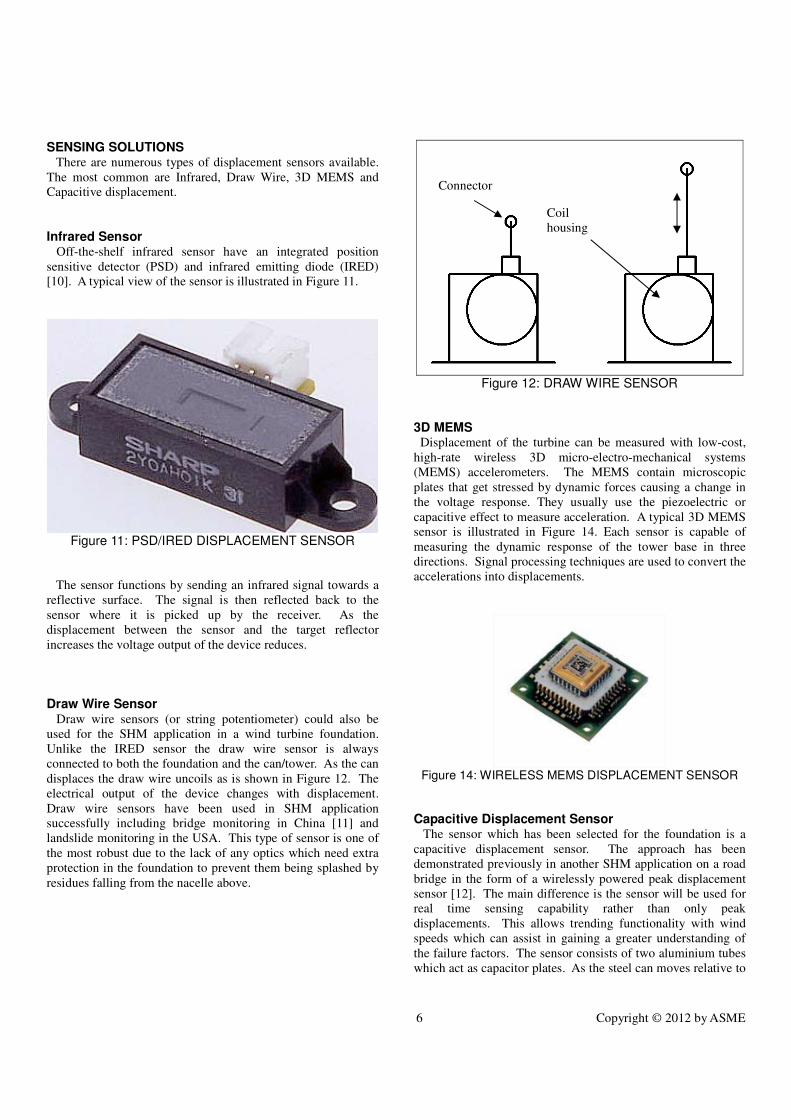
SENSING SOLUTIONS There are numerous types of displacement sensors available.
The most common are Infrared, Draw Wire, 3D MEMS and
Capacitive displacement.
Infrared Sensor
Off-the-shelf infrared sensor have an integrated position
sensitive detector (PSD) and infrared emitting diode (IRED)
[10]. A typical view of the sensor is illustrated in Figure 11.
Figure 11: PSD/IRED DISPLACEMENT SENSOR
The sensor functions by sending an infrared signal towards a
reflective surface. The signal is then reflected back to the
sensor where it is picked up by the receiver. As the
displacement between the sensor and the target reflector
increases the voltage output of the device reduces.
Draw Wire Sensor Draw wire sensors (or string potentiometer) could also be
used for the SHM application in a wind turbine foundation.
Unlike the IRED sensor the draw wire sensor is always
connected to both the foundation and the can/tower. As the can
displaces the draw wire uncoils as is shown in Figure 12. The
electrical output of the device changes with displacement.
Draw wire sensors have been used in SHM application
successfully including bridge monitoring in China [11] and
landslide monitoring in the USA. This type of sensor is one of
the most robust due to the lack of any optics which need extra
protection in the foundation to prevent them being splashed by
residues falling from the nacelle above.
Figure 12: DRAW WIRE SENSOR
3D MEMS Displacement of the turbine can be measured with low-cost,
high-rate wireless 3D micro-electro-mechanical systems
(MEMS) accelerometers. The MEMS contain microscopic
plates that get stressed by dynamic forces causing a change in
the voltage response. They usually use the piezoelectric or
capacitive effect to measure acceleration. A typical 3D MEMS
sensor is illustrated in Figure 14. Each sensor is capable of
measuring the dynamic response of the tower base in three
directions. Signal processing techniques are used to convert the
accelerations into displacements.
Figure 14: WIRELESS MEMS DISPLACEMENT SENSOR
Capacitive Displacement Sensor The sensor which has been selected for the foundation is a
capacitive displacement sensor. The approach has been
demonstrated previously in another SHM application on a road
bridge in the form of a wirelessly powered peak displacement
sensor [12]. The main difference is the sensor will be used for
real time sensing capability rather than only peak
displacements. This allows trending functionality with wind
speeds which can assist in gaining a greater understanding of
the failure factors. The sensor consists of two aluminium tubes
which act as capacitor plates. As the steel can moves relative to
Connector
Coil
housing

7 Copyright © 2012 by ASME
the static foundation the capacitance of the device changes as
the area of overlapping contact area decreases. The sensor is
connected to a voltage source and capacitance. As the
displacement varies the overlapping area of the capacitance
plates changes in a proportional manner. The varying
capacitance results to voltages changes which can be digitally
captured and processed. The basic layout of the two capacitor
tubes is displayed in Figure 13.
Figure 13: CAPACITOR LAYOUT
The capacitance (C) varies proportionally to the overlap height
of the two cylinders (h) as shown in Eqn. (1). It is also
proportional to the dielectric constant (K), the air permittivity
(ε0) is the permittivity and inversely proportional to the distance
between cylinders (d).
(1)
The rate of change of the capacitance in respect to the overlap
height is defined by the first derivative (Eqn. 2):
Finally, the captured voltage levels will be correlated with
displacement values during the testing phase.
7. CONDITION MONITORING
Data gathered from the chosen sensor system will be
gathered, analyzed and displayed in manner suitable for the
asset owner. A Bayesian Inference Program will be used to
determine the state of the foundation condition.
LabVIEW Bayesian Inference Program To analyse data from each sensor a Bayesian inference
program will be used. Initially, probability density functions
(pdf) are created for each foundation condition (Green, Amber
and Red). An example is shown in Figure 14 where three pdfs
for three component temperature conditions are displayed. For
the foundation monitoring system temperature will be replaced
with displacement.
Figure 14: PROBABILITY OF A TEMPERATURE GIVEN COMPONENT CONDITION IS: GOOD, ABNORMAL OR CRITICAL
Once the sensor is active, data is fed into the Bayesian
inference program (BIP) where it determines the state condition
of the foundation. The output is a simple traffic light system
which is easy and quick to interpret by the technician staff
monitoring the foundations. Three typical operating modes are
displayed in Figure 15 for a wind turbine monitoring. The wind
turbine foundation monitoring solution will be simpler as it will
only track a single input value. It is envisaged that additional
inputs, such as wind speed will be added. It is also quick and
easy to change the levels of each of the three conditions, for
example to change the critical limit from 5mm displacement to
6mm.
(2)

8 Copyright © 2012 by ASME
Figure 15: CRITICAL CONDITION
Communication System Architecture A proposed communications system architecture is shown in
Figure 16. Multiple sensors (S) will be deployed on the turbine
foundation sampling continuously for displacement and report
the measurements to a data aggregator device (A) located in the
turbine. The communications between the sensors and the data
aggregation device could be either wired or wireless. In order to
reduce the installation cost and ease deployment a wireless
solution based on the widely used and mature communications
standard IEEE 802.15.4 [13] will be adopted. Using this
technology devices can operate for more than 3 years with two
AAA batteries reporting every 10 seconds [14] making it ideal
for SHM applications.
Wind Farm
G
Site Office
G
Site Office
S
S
S
S
S S
SS
A
Remote Technical
Centre
A Aggregator G Gateway S Sensor
Wind Farm
AA
A
A
A
Link
AA
A AA
Turbine Tower
Cross Section
Figure 16: COMMUNICATIONSYSTEM ARCHITECTURE
Aggregator devices are used to combine measurements from
the displacement sensors in order to create a displacement
profile of the tower as a whole. Also correlation of
displacement readings and measurement verification can be
achieved at this level (for example elimination of ambiguous
readings from sensors placed on the same proximity).
After initial processing, the aggregator devices transmit the
combined measurements over the existing SCADA
infrastructure to the Remote Technical Centre (RTC) for further
processing and classification using a traffic-light system (green,
amber, red). The classification and processing will be
performed by Bayesian Inference Program and allow the
Human Machine Interface (HMI) to display the status of each
individual turbine in an easy to understand format. In this
scenario the gateway devices (G) shown in
Figure 16, are not necessary since communications are handled
directly by the existing SCADA infrastructure. Also note that
the Bayesian Inference Program will be executed in the Remote
Technical Centre.
For wind farms where SCADA infrastructure is restricted or
not available due to warranty issues, an autonomous
communications solution will be provided. In this scenario,
aggregator devices will transmit aggregate measurements to a
gateway device (G) which is physically located in the Site
Office. The gateway device will have two communication
interfaces:
• A wireless interface to communicate with the aggregators.
This interface will be based on IEEE 802.15.4 and enlist
the aid of aggregators to route measurements from remote
locations of the wind farm (i.e. turbines which do not have
a direct link to the site office due to limited range).
• An Internet capable interface (i.e. GPRS/HSDPA,
WiMAX, Ethernet, ADSL, Cable) for communications
with the Remote Technical Centre.
In order to minimize the communications overhead over
the Internet link, the Bayesian Inference Program will perform
the classification on the gateway device and while the turbine
status is green only update notifications will be send back to the
Remote Technical Centre for HMI purposes. When the turbine
status changes to amber and red, then the gateway will stream
measurements back to the RTC along with the normal
notifications for further processing, inspection and analysis
from technical staff.
If a wind farm consists of a large number of turbines,
multiple gateway devices may be deployed increasing data
communication bandwidth, reliability and availability.
It is proposed displacement data is trended with real time
wind speeds from anemometer point measurements enabling
the operator to gain clear indication of relationship between
movement and damage. It is expected that displacements are
the highest during start up and shut down events and periods of
extreme weather conditions. Further work must be undertaken
to test and commission the solution and to prove it is robust for
this application.

9 Copyright © 2012 by ASME
CONCLUSION Embedded can wind turbine foundations have been
displaying signs of failure in the form of vertical displacement.
Several inexpensive sensors have been suggested as being
suitable for integration in a simple SHM system to continuously
monitor real-time displacements in embedded can style wind
turbine foundations. The proposed data acquisition and
processing architecture allows the asset operator to reduce
inspection costs whilst providing greater levels of real time
information. Future work will report on field assessments
captured from the developed SHM system and provide greater
insight to failure modes. This work will also comment on the
recommended number of sensors and layout.
NOMENCLATURE
ADSL Asymmetric Digital Subscriber Line
AE Acoustic Emission
C Capacitance
CM Condition Monitoring
d Gap distance in sensor
EMI Electromagnetic Interference
h Overlap between sensor plates
HMI Human Machine Interface
G Gateway Device
GPRS General Packet Radio Service
IRED Infrared Emitting Diode
K Dielectric constant
MEMS Micro Electrical-Mechanical Sensor
PSD Position Sensitive Detector
r Radius
RTC Remote Technical Centre
SCADA Supervisory Control and Data Acquisition
SHM Structural Health Monitoring
WiMAX Worldwide Interoperability for Microwave Access
WMEP Wind Energy Management and Evaluation Program
Free space permittivity
ACKNOWLEDGEMENTS
(i) EPSRC Wind Energy Systems Centre for Doctoral Training,
University of Strathclyde, Glasgow.
(ii) Centre for Advanced Condition Monitoring, University of
Strathclyde, Glasgow.
REFERENCES
1. DECC, UK Renewable Energy Roadmap. Department
of Energy and Climate Change, 2011.
2. Burton, T., et al., Wind Energy Handbook. 2001,
Chichester: John Wiley and Sons. 211-219.
3. Ciang, C.C., J.R. Lee, and H.J. Bang, Structural health
monitoring for a wind turbine system: a review of
damage detection methods. Measurement Science &
Technology, 2008. 19(12).
4. Hamilton, A. and F. Quail, Detailed State of the Art
Review for the Different Online/Inline Oil Analysis
Techniques in Context of Wind Turbine Gearboxes.
Journal of Tribology, 2011. 133(4): p. 044001.
5. Tavnet, P.J., G.J.W. Van Bussel, and F. Spinato.
Machine and Converter Reliabilities in Wind Turbines.
in Power Electronics, Machines and Drives, 2006. The
3rd IET International Conference on. 2006.
6. Echavarria, E., et al., Reliability of Wind Turbine
Technology Through Time. Journal of Solar Energy
Engineering, 2008. 130(3): p. 031005-8.
7. Faulstich, S., B. Hahn, and P.J. Tavner, Wind turbine
downtime and its importance for offshore deployment.
Wind Energy, 2011. 14(3): p. 327-337.
8. Ribrant, J. and L.M. Bertling, Survey of failures in
wind power systems with focus on Swedish wind
power plants during 1997-2005. Ieee Transactions on
Energy Conversion, 2007. 22(1): p. 167-173.
9. Vestas. V80 - 2.0MW. 2011 [cited 2012 14/02/2012];
Available from: http://www.vestas.com/en/wind-
power-plants/procurement/turbine-overview/v80-2.0-
mw.aspx#/vestas-univers.
10. Sharp. GP2Y0AH01K0F. 2007 [cited 2012
22/02/2012]; Available from:
http://www.sharpsme.com/webfm_send/1476.
11. Qian, Z.D., Y.H. Fan, and Z.B. Lu, Application of
draw-wire displacement sensors on structural health
monitoring of Jiangyin Bridge - art. no. 617619, in
Nondestructive Evaluation and Health Monitoring of
Aerospace Materials, Composites, and Civil
Infrastructure V, A.A. Mufti, A.L. Gyekenyesi, and
P.J. Shull, Editors. 2006, Spie-Int Soc Optical
Engineering: Bellingham. p. 17619-17619.
12. Mascarenas, D., et al., A Mobile Host Approach for
Wireless Powering and Interrogation of Structural
Health Monitoring Sensor Networks. Ieee Sensors
Journal, 2009. 9(12): p. 1719-1726.
13. IEEE Standard for Local and metropolitan area
networks--Part 15.4: Low-Rate Wireless Personal
Area Networks (LR-WPANs). IEEE Std 802.15.4-2011
(Revision of IEEE Std 802.15.4-2006), 2011: p. 1-314.
14. Casilari, E., et al. Characterization of battery
consumption in 802.15.4/ZigBee sensor motes. in
Industrial Electronics (ISIE), 2010 IEEE International
Symposium on. 2010.

10 Copyright © 2012 by ASME


![International Experience at Strathclyde - mabbett.eu · Spring 2013 - Issue 09] Caption Strathclyde Students Triumph Again at Talent Discovery Event [Strathclyde Students Triumph](https://img.pdfslide.net/doc/110x75/5e1039f32863e50a3d68e760/international-experience-at-strathclyde-spring-2013-issue-09-caption-strathclyde.jpg)