Embed Size (px)
Citation preview
Assembly andMaintenance InstructionsMechanical Sliding Caliper Disc BrakeType NG 22
1th Edition
Copyright WABCO 2007
Vehicle Control Systems
The right of amendment is reservedVersion 001/05.06(en)
8150101283 815 010 128 3

31
Table of Contents
Page
1. Description of the Mechanical Sliding Caliper Disc Brake 4
1.1 Introduction 4
2. Service Instructions 6
2.1 Safety tips during repair 6
2.2 Checking brake function 6
2.2.1 Checking the adjustment 7
2.3 Checking the brake pads 8
2.4 Checking the brake disc 9
3. Renewing brake pads 10
4. Renewing brake 17
5. Renewing gaiters 18
5.1 Renewing guide pin gaiters and bushes 19
5.2 Renewing adjuster screw gaiter 24
6. Renewing brake cylinder 26
Table 1: Spanner widths [AF] and tightening torques [Nm] 27
Exploded view of the exchange units NG 22 28
Note:The Service Instruction focuses on trained specialists. Operations on the brake can only becarried out if the appropriate paragraphs have been read through and understood. The safetyinstructions according to paragraph 2.1 are to be considered and to be followed.
These Service Instructions are copyright. All rights reserved.
This publication is not subject to any update service. You will find the latest versions inINFORM under www.wabco-auto.com when quotingthe publications number 815 010 128 3.
No part of this publication maybe reproduced, stored in a retrieval system, or transmitted inany form or by any means, electronic, photocopying, recording or otherwise without permis-sion in writing from WABCO Radbremesen GmbH.
4
Mechanical Sliding Caliper Disc BrakeNG 22
1
1. Description of the Mechanical Sliding Caliper Disc Brake1.1 Introduction
The brake “NG 22” is a new developed one-piston-brake, which is intended for use in commercial vehiclesand trailers on front and rear axles for 22,5" wheel rimsas service, auxiliary and parking brake. It is actuatedmechanically via a diaphragm brake cylinder or a springbrake actuator. This is mounted to the end cover of thebrake caliper.
A very compact unit is achieved by the direct mountingof the brake cylinder onto the caliper. This enables opti-mal utilisation of the installation situations.
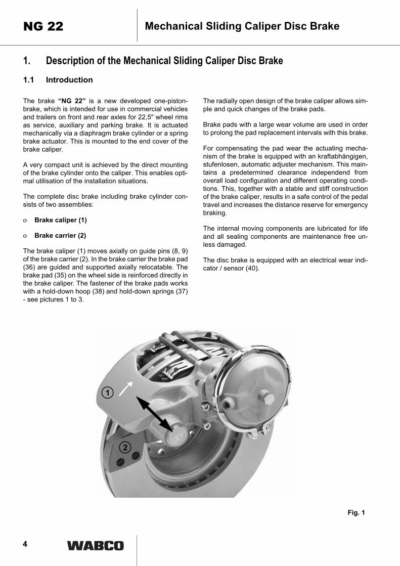
The complete disc brake including brake cylinder con-sists of two assemblies:
o Brake caliper (1)
o Brake carrier (2)
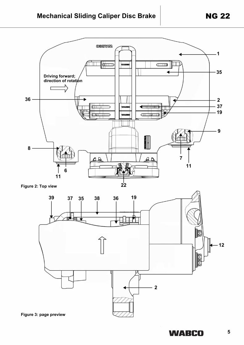
The brake caliper (1) moves axially on guide pins (8, 9)of the brake carrier (2). In the brake carrier the brake pad(36) are guided and supported axially relocatable. Thebrake pad (35) on the wheel side is reinforced directly inthe brake caliper. The fastener of the brake pads workswith a hold-down hoop (38) and hold-down springs (37)- see pictures 1 to 3.
The radially open design of the brake caliper allows sim-ple and quick changes of the brake pads.
Brake pads with a large wear volume are used in orderto prolong the pad replacement intervals with this brake.
For compensating the pad wear the actuating mecha-nism of the brake is equipped with an kraftabhängigen,stufenlosen, automatic adjuster mechanism. This main-tains a predetermined clearance independend fromoverall load configuration and different operating condi-tions. This, together with a stable and stiff constructionof the brake caliper, results in a safe control of the pedaltravel and increases the distance reserve for emergencybraking.
The internal moving components are lubricated for lifeand all sealing components are maintenance free un-less damaged.
The disc brake is equipped with an electrical wear indi-cator / sensor (40).
1
2
Fig. 1
5
Mechanical Sliding Caliper Disc Brake NG 22
Figure 2: Top view
Figure 3: page preview
1
2
35
19
9
37
22
8
39 37 35 38 36 19
2
12
711
611
Driving forward;direction of rotation
36
6
Mechanical Sliding Caliper Disc BrakeNG 22
2. Service Instructions
This instruction with the following pictures contains therequired steps and work sequences to replace the avail-able repair kits. The spanner size and the tightening tor-ques in the sequences are listed in table 1 (see page27). For lubrication use only the tube of grease supplied withthe WABCO brake repair kit.
2.1 Safety tips to be considered during repair
The flawless technical condition of the disc brake is mostimportant to ensure good driving and safe braking char-acteristics.
Observe brake pad and disc wear limits!Worn-out pads and discs reduce the brakeeffectiveness and cause brake failure! Dan-ger of accidents! Burned, glazed or oil con-taminated brake pads must be replacedimmediately. Always replace brake pads on a per axlebasis!
During repairs on the brake the vehicle mustbe parked on a level surface and blocked toprevent rollaway. Only approved and suitablefixtures are to be used for the lifting andblocking of the vehicle. While working on thebrake ensure that the brake cannot be actu-ated inadvertently. Do not actuate the brake while the brakepads are removed. Danger of bodily inju-ry!
Do not clean the brake with pressurised air orother high cleaning pressure apparatus.Danger of bodily injury! Danger of destruc-tion of rubber parts!
Keep hands and fingers out of the inside ofthe caliper to avoid injury!
A second technican must assist during re-moval and installation of the brake. Heavyload - Danger of bodily injury!
During repairs outside of the vehicle, thebrake must be secured in a fixture, such as aheavy vise as high torque is required duringremoval and installation of the bolts. Largeloosening and tightening torques of thescrew connexions - Danger of bodily injury!
The brake caliper with clamping unit shall not beopened. Therefore the bolts holding the cover shall notbe loosened.
Only original and genuine WABCO Service Parts andapproved brake pads are to be used.
During repairs use only recommended tools. Do not usea power-driven socket or tools! Tighten nuts and boltsonly to specified torque limits.
With newly installed brake pads during the first 50 km noemergency stops should be made if possible. Also avoidlong braking cycles and forced braking.
When wear of the cast brake parts such as cracks orheavy abrasion is noticied replace the entire brake as-sembly according to the instructions.
Upon completion of repairs the vehicle's braking systemmust be tested on a roller dynamometer. If no roller dy-namometer is available a driving test with brake applica-tions must be perfomed.
2.2 Checking brake function
Attention: Do not use a power-driven socket! Whileworking at the brake or moving the brakecaliper handle the caliper only from out-side to avoid injury!

7
2.2.1 Checking the adjustmentGeneral note:The turning directions and the torques for the hexagonon the adjuster nut are given in table 1, position I. Theactuation cylinder does not need to be removed for thischeck.
Work sequences:• Remove plug (12) for the adjuster from the caliper
(22) carefully.
Caution: On disassembly the proper tool position isagainst the plug (12) set in the anular groove!
Caution: Internal seal with the development do notdamage!
• Using a AF 8 ring spanner turn the adjuster (22) hex-agon approx. 1/2 turn in the clockwise direction.
Attention: Do not overload the adjuster hexagon(22)! Do not use an open-ended spanner. With thering spanner mounted on the adjuster nut ensurethat there is sufficient such that it will not be pre-vented from turning during the adjuster check!
Mechanical Sliding Caliper Disc Brake NG 22
22
Fig. 4
12
Fig. 5 12 22
8
Mechanical Sliding Caliper Disc BrakeNG 22
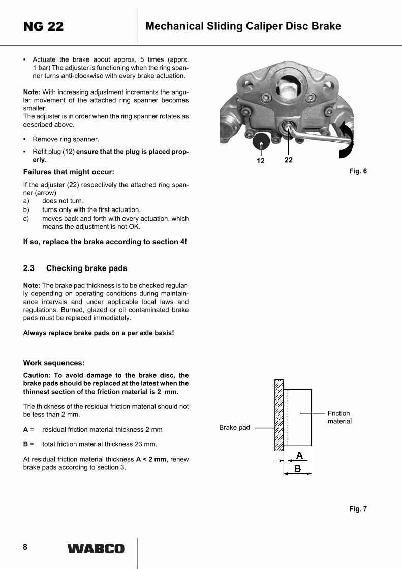
• Actuate the brake about approx. 5 times (apprx.1 bar) The adjuster is functioning when the ring span-ner turns anti-clockwise with every brake actuation.
Note: With increasing adjustment increments the angu-lar movement of the attached ring spanner becomessmaller.The adjuster is in order when the ring spanner rotates asdescribed above.
• Remove ring spanner.
• Refit plug (12) ensure that the plug is placed prop-erly.
Failures that might occur:If the adjuster (22) respectively the attached ring span-ner (arrow)a) does not turn.b) turns only with the first actuation.c) moves back and forth with every actuation, which
means the adjustment is not OK.
If so, replace the brake according to section 4!
2.3 Checking brake pads
Note: The brake pad thickness is to be checked regular-ly depending on operating conditions during maintain-ance intervals and under applicable local laws andregulations. Burned, glazed or oil contaminated brakepads must be replaced immediately.
Always replace brake pads on a per axle basis!
Work sequences:Caution: To avoid damage to the brake disc, thebrake pads should be replaced at the latest when thethinnest section of the friction material is 2 mm.
The thickness of the residual friction material should notbe less than 2 mm.
A = residual friction material thickness 2 mm
B = total friction material thickness 23 mm.
At residual friction material thickness A < 2 mm, renewbrake pads according to section 3.
Fig. 6
Fig. 7
Friction
Brake pad
12 22
material

9
Measuring of wearThe average brake pad wear can be measured, depend-ing on the access, at the close fit (longer guide pin at thebrake disc entry) or at the clearence fit (shorter guide pinat the brake disc exit).
Therefore measure the thickness (X) of the flange of theaxle and the distance (Y) between the flange and theedge of the brake caliper of the particular close fit (ar-rows).
The maximum wear is reached or exceeded wtih the fol-lowing values.
Shorter guide pin:maximum wear X + Y > 90.5 mmChange lining
Longer guide pin:maximum wear X + Y > 129.5 mmChange lining
2.4 Checking brake disc
Work sequences:• Remove brake pads according to section 3.
• Measure disc thickness over the rubbing faces.
C = total disc thickness - new 45 mm
D = wear allowance limit 37 mm, the brake discmust be renewed. The renewal is recommend-ed on a per axle basis.
E = total pad thickness - new 32 mm
F = pad backplate thickness 9 mm
G = minimum residual friction material thickness 2 mm
H = absolute minimum pad and pad backplatethickness 11 mm, the brake pads must be renewed.
Attention:Observe brake pad and disc wear limits!Worn-out pads and discs reduce thebrake effectiveness and cause brake fail-ure! Danger of accidents!
Mechanical Sliding Caliper Disc Brake NG 22
Fig. 8
Fig. 9
XY
10
Mechanical Sliding Caliper Disc BrakeNG 22
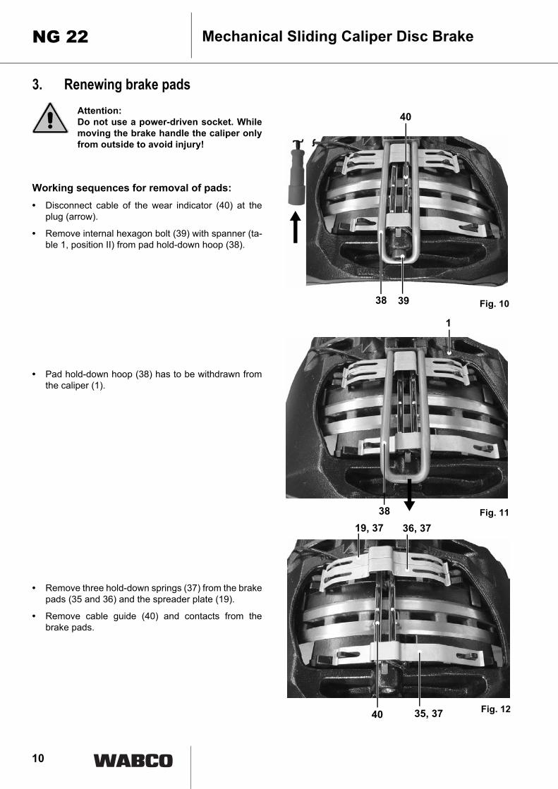
3. Renewing brake padsAttention: Do not use a power-driven socket. Whilemoving the brake handle the caliper onlyfrom outside to avoid injury!
Working sequences for removal of pads:• Disconnect cable of the wear indicator (40) at the
plug (arrow).
• Remove internal hexagon bolt (39) with spanner (ta-ble 1, position II) from pad hold-down hoop (38).
• Pad hold-down hoop (38) has to be withdrawn fromthe caliper (1).
• Remove three hold-down springs (37) from the brakepads (35 and 36) and the spreader plate (19).
• Remove cable guide (40) and contacts from thebrake pads.
Fig. 10
Fig. 11
Fig. 12
3938
40
38
1
40 35, 37
19, 37 36, 37
11
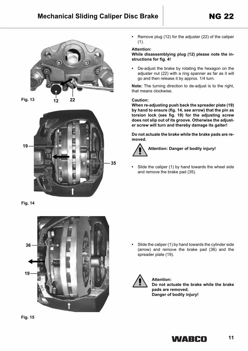
• Remove plug (12) for the adjuster (22) of the caliper(1).
Attention: While disassemblying plug (12) please note the in-structions for fig. 4!
• De-adjust the brake by rotating the hexagon on theadjuster nut (22) with a ring spanner as far as it willgo and then release it by approx. 1/4 turn.
Note: The turning direction to de-adjust is to the right,that means clockwise.
Caution: When re-adjusting push back the spreader plate (19)by hand to ensure (fig. 14, see arrow) that the pin astorsion lock (see fig. 19) for the adjusting screwdoes not slip out of its groove. Otherwise the adjust-er screw will turn and thereby damage its gaiter!
Do not actuate the brake while the brake pads are re-moved.
Attention: Danger of bodily injury!
• Slide the caliper (1) by hand towards the wheel sideand remove the brake pad (35).
• Slide the caliper (1) by hand towards the cylinder side(arrow) and remove the brake pad (36) and thespreader plate (19).
Attention: Do not actuate the brake while the brakepads are removed. Danger of bodily injury!
Mechanical Sliding Caliper Disc Brake NG 22
Fig. 13
Fig. 14
Fig. 15
19
35
2212
19
36

12
Mechanical Sliding Caliper Disc BrakeNG 22
• Using a wire brush remove any corrosion from thespreader plate, brake pad slot and brake pads guidesurfaces.
Caution: Take care not to damage the dust caps (5, 10). Theguide surfaces must be free of grease!
Checking the dust caps (gaiters) and the brakecaliper movement:• Slide the caliper towards the side to allow examina-
tion of the gaiters (5, 10), the guide pins (8, 9) and theadjuster screw (21) for wear and damage. Renewdefective gaiters! (see section 5.1 and 5.2).
Caution: In case of a defective the gaiter (10) must bechecked if dirt or water has already entered or dam-aged the inner parts of the brake or the gaiter seat inthe caliper by corrosion. In case of doubt the brakemust be renewed according to section 4. If the gaiter(10) is damaged while the brake is serviced, the gai-ter must be renewed according to section 5.2.
• Slide the caliper on the guide pins by hand over its to-tal displacement and check for freedom of move-ment. If the movement is restricted renew theguide pins bushes and gaiters according to sec-tion 5.1
Caution: Do not squeeze the dust caps of the guide pinsagainst the brake carrier!
Fig. 16
Fig. 17
Fig. 18
10, 21
5, 8
5 10 5
5, 9

13
Checking of the adjuster unit (clamping unit):• Secure the adjuster nut during checking and turning
on the hexagon from twisting, e.g. by holding the pin(see arrow).
• Extend the adjuster (22) towards the brake disc byturning the adjuster hexagon in the anti-clockwise di-rection with a ring spanner and check for ease ofmovement.
• After checking the adjuster unit return the adjustescrew completely by turning in the clock-wise direc-tion.
Note: The torque to return the adjuster screw is greaterthan the torque to turn the torque towards the disc.
Caution: Do not overload the adjuster hexagon! Do not usean open-ended spanner. With the ring spannermounted on the adjuster nut ensure that there is suf-ficient such that it will not be prevented from turningduring the adjuster check.
• Actuate the brake lightly several times and check thatthe adjuster unit automatically adjusts. The ringspanner will turn with every brake actuation.
Attention: Do not touch any part of thebrake while testing.
Brake disc condition inspection:Check brake disc for cracks, condition of the rubbingfaces and maximum wear dimension.
A= crazing = permissible
B = Radial cracksto max: 0.5 mm width = permissible
C = unevennedd under 1.5 mm of the plate surface = permisssible
D = continuous cracks = not permissible
a= braking surface
Mechanical Sliding Caliper Disc Brake NG 22
Fig. 19
Fig. 20
Fig. 21
22
14
Mechanical Sliding Caliper Disc BrakeNG 22
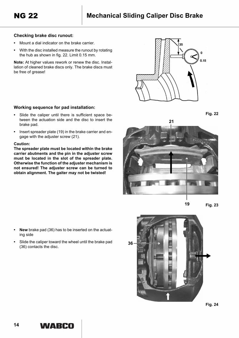
Checking brake disc runout:• Mount a dial indicator on the brake carrier.
• With the disc installed measure the runout by rotatingthe hub as shown in fig. 22. Limit 0.15 mm.
Note: At higher values rework or renew the disc. Instal-lation of cleaned brake discs only. The brake discs mustbe free of grease!
Working sequence for pad installation:• Slide the caliper until there is sufficient space be-
tween the actuation side and the disc to insert thebrake pad.
• Insert spreader plate (19) in the brake carrier and en-gage with the adjuster screw (21).
Caution: The spreader plate must be located within the brakecarrier abutments and the pin in the adjuster screwmust be located in the slot of the spreader plate.Otherwise the function of the adjuster mechanism isnot ensured! The adjuster screw can be turned toobtain alignment. The gaiter may not be twisted!
• New brake pad (36) has to be inserted on the actuat-ing side
• Slide the caliper toward the wheel until the brake pad(36) contacts the disc.
Fig. 22
Fig. 23
Fig. 24
19
21
36
15
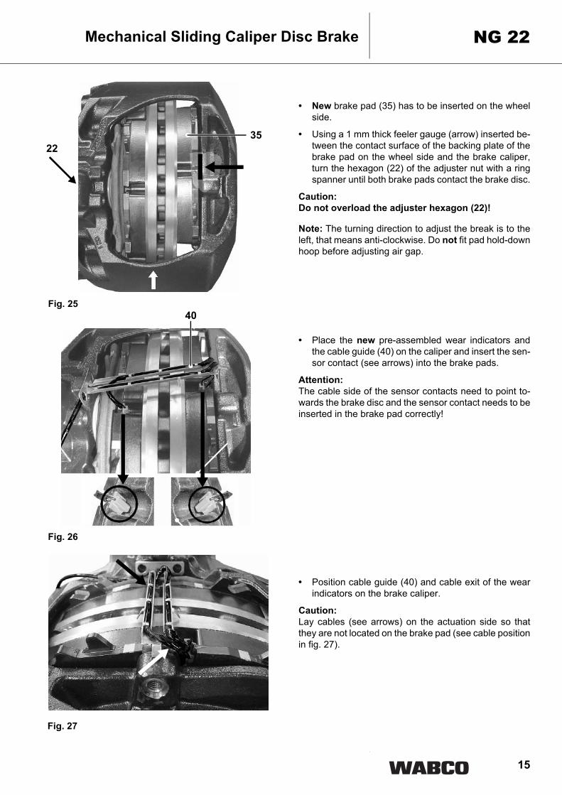
• New brake pad (35) has to be inserted on the wheelside.
• Using a 1 mm thick feeler gauge (arrow) inserted be-tween the contact surface of the backing plate of thebrake pad on the wheel side and the brake caliper,turn the hexagon (22) of the adjuster nut with a ringspanner until both brake pads contact the brake disc.
Caution: Do not overload the adjuster hexagon (22)!
Note: The turning direction to adjust the break is to theleft, that means anti-clockwise. Do not fit pad hold-downhoop before adjusting air gap.
• Place the new pre-assembled wear indicators andthe cable guide (40) on the caliper and insert the sen-sor contact (see arrows) into the brake pads.
Attention: The cable side of the sensor contacts need to point to-wards the brake disc and the sensor contact needs to beinserted in the brake pad correctly!
• Position cable guide (40) and cable exit of the wearindicators on the brake caliper.
Caution: Lay cables (see arrows) on the actuation side so thatthey are not located on the brake pad (see cable positionin fig. 27).
Mechanical Sliding Caliper Disc Brake NG 22
Fig. 25
Fig. 27
40
Fig. 26
3522

16
Mechanical Sliding Caliper Disc BrakePAN 22
• Position the new hold down springs (37) over the ca-ble guide and on top of the spreader plate (19) andthe brake pads (35, 36).
Caution: The hold-down spring (37) is placed withthe long side on the brake pad (35). The long side ofthe hold-down spring points to the brake disc trail-ing side (arrow).
• Slide new hold down hoop 38 through opening in thecable guide and openings in the brake caliper, thenpush downward so that the radial corners of the holddown springs snap into the hold down hoop.
• Fit new internal hexagon bolt (39) to the brake cali-per (Table 1 Position II) with required tighteningtorque.
Fig. 28
Fig. 29
Fig. 30
37
39
35
38
36
17
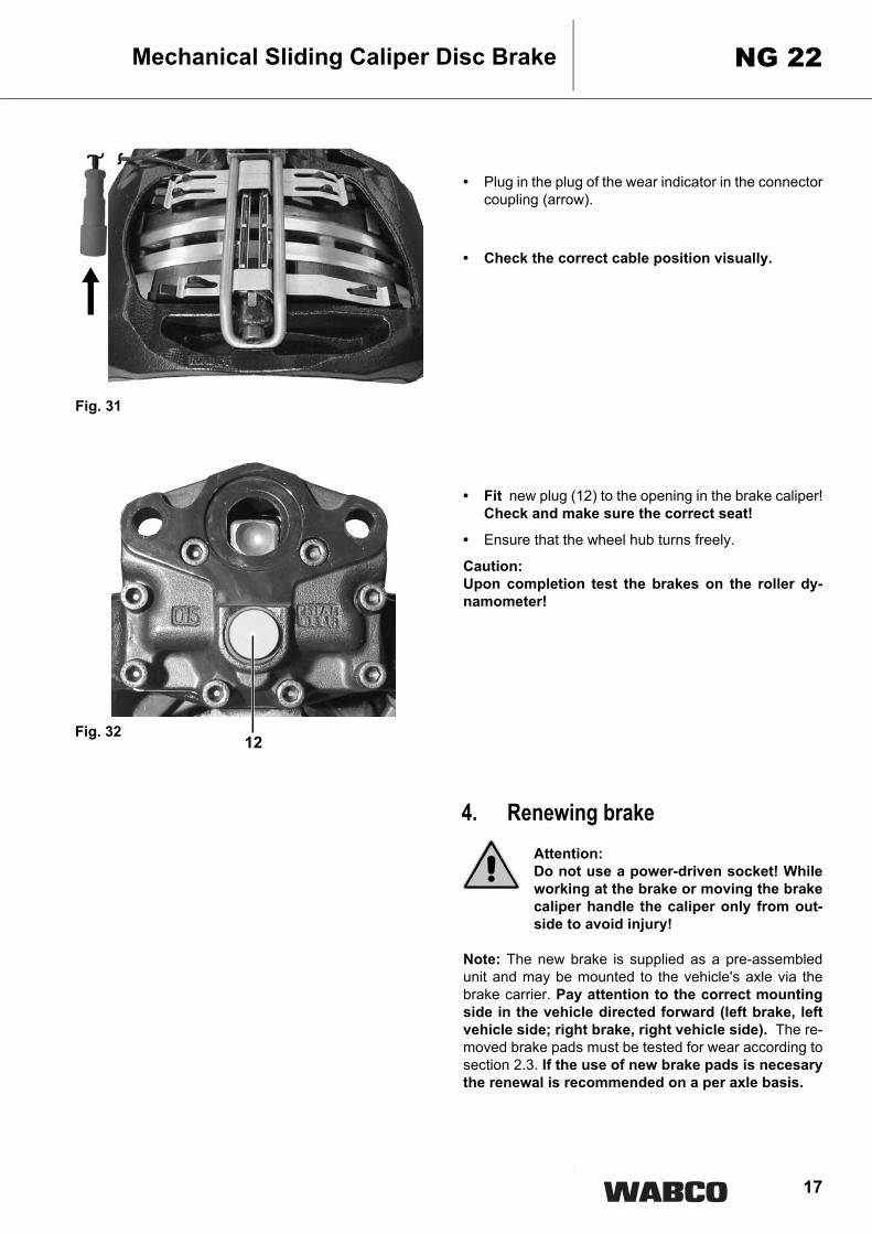
• Plug in the plug of the wear indicator in the connectorcoupling (arrow).
• Check the correct cable position visually.
• Fit new plug (12) to the opening in the brake caliper!Check and make sure the correct seat!
• Ensure that the wheel hub turns freely.
Caution: Upon completion test the brakes on the roller dy-namometer!
4. Renewing brakeAttention: Do not use a power-driven socket! Whileworking at the brake or moving the brakecaliper handle the caliper only from out-side to avoid injury!
Note: The new brake is supplied as a pre-assembledunit and may be mounted to the vehicle's axle via thebrake carrier. Pay attention to the correct mountingside in the vehicle directed forward (left brake, leftvehicle side; right brake, right vehicle side). The re-moved brake pads must be tested for wear according tosection 2.3. If the use of new brake pads is necesarythe renewal is recommended on a per axle basis.
Mechanical Sliding Caliper Disc Brake NG 22
Fig. 31
Fig. 3212
18
Mechanical Sliding Caliper Disc BrakeNG 22
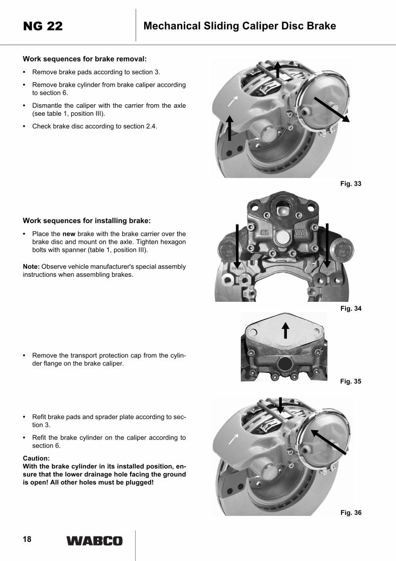
Work sequences for brake removal:
• Remove brake pads according to section 3.
• Remove brake cylinder from brake caliper accordingto section 6.
• Dismantle the caliper with the carrier from the axle(see table 1, position III).
• Check brake disc according to section 2.4.
Work sequences for installing brake:
• Place the new brake with the brake carrier over thebrake disc and mount on the axle. Tighten hexagonbolts with spanner (table 1, position III).
Note: Observe vehicle manufacturer's special assemblyinstructions when assembling brakes.
• Remove the transport protection cap from the cylin-der flange on the brake caliper.
• Refit brake pads and sprader plate according to sec-tion 3.
• Refit the brake cylinder on the caliper according tosection 6.
Caution: With the brake cylinder in its installed position, en-sure that the lower drainage hole facing the groundis open! All other holes must be plugged!
Fig. 33
Fig. 34
Fig. 35
Fig. 36

19
5. Renewing gaitersAttention: Do not use a power-driven socket! Whileworking at the brake or moving the brakecaliper handle the caliper only from out-side to avoid injury!
Note: When replacing all of the gaiters in the caliper, thework sequences 5.1 and 5.2 are to be combined. In thiscase work sequences do not need to be repeated sever-al times.
When replacing individual gaiters, follow the corre-sponding work sequences of the sections 5.1 and 5.2.
5.1 Renewing guide pin gaiters andbushes
Working sequences for removal:• Remove brake pads according to section 3.
• Remove brake cylinder from brake caliper accordingto section 6.
• Dismantle the caliper with the carrier from the axleaccording to section 4.
• Dismantle brake caliper (1) from brake carrier (2) byremoving sealing caps (11) of the guide pins (8, 9)from the caliper (1) with a suitable tool, e.g. chisel.
Caution: Take care not to damage cover bores in housing.Position the proper tool on the cover.
Mechanical Sliding Caliper Disc Brake NG 22
Fig. 38
Fig. 37
11 8, 9
1
2
F
20
Mechanical Sliding Caliper Disc BrakeNG 22
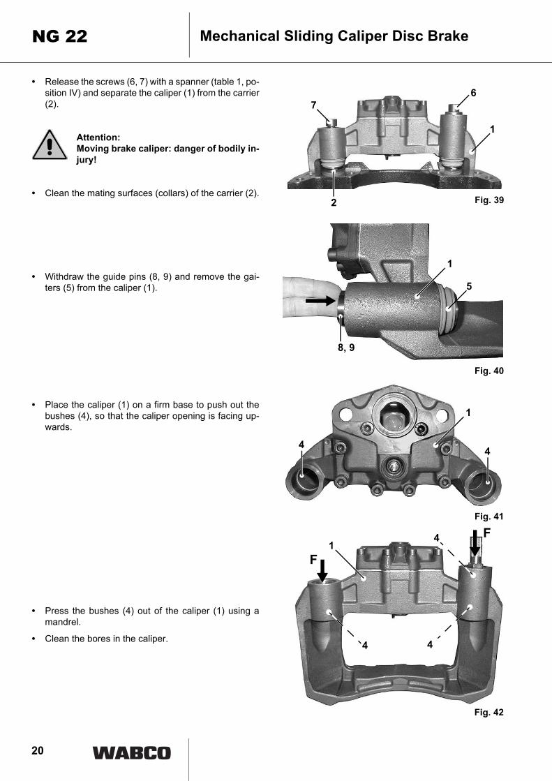
• Release the screws (6, 7) with a spanner (table 1, po-sition IV) and separate the caliper (1) from the carrier(2).
Attention: Moving brake caliper: danger of bodily in-jury!
• Clean the mating surfaces (collars) of the carrier (2).
• Withdraw the guide pins (8, 9) and remove the gai-ters (5) from the caliper (1).
• Place the caliper (1) on a firm base to push out thebushes (4), so that the caliper opening is facing up-wards.
• Press the bushes (4) out of the caliper (1) using amandrel.
• Clean the bores in the caliper.
Fig. 40
Fig. 39
Fig. 42
4
1
Fig. 41
67
1
2
5
8, 9
4 4
1
1F
F
4
4
21
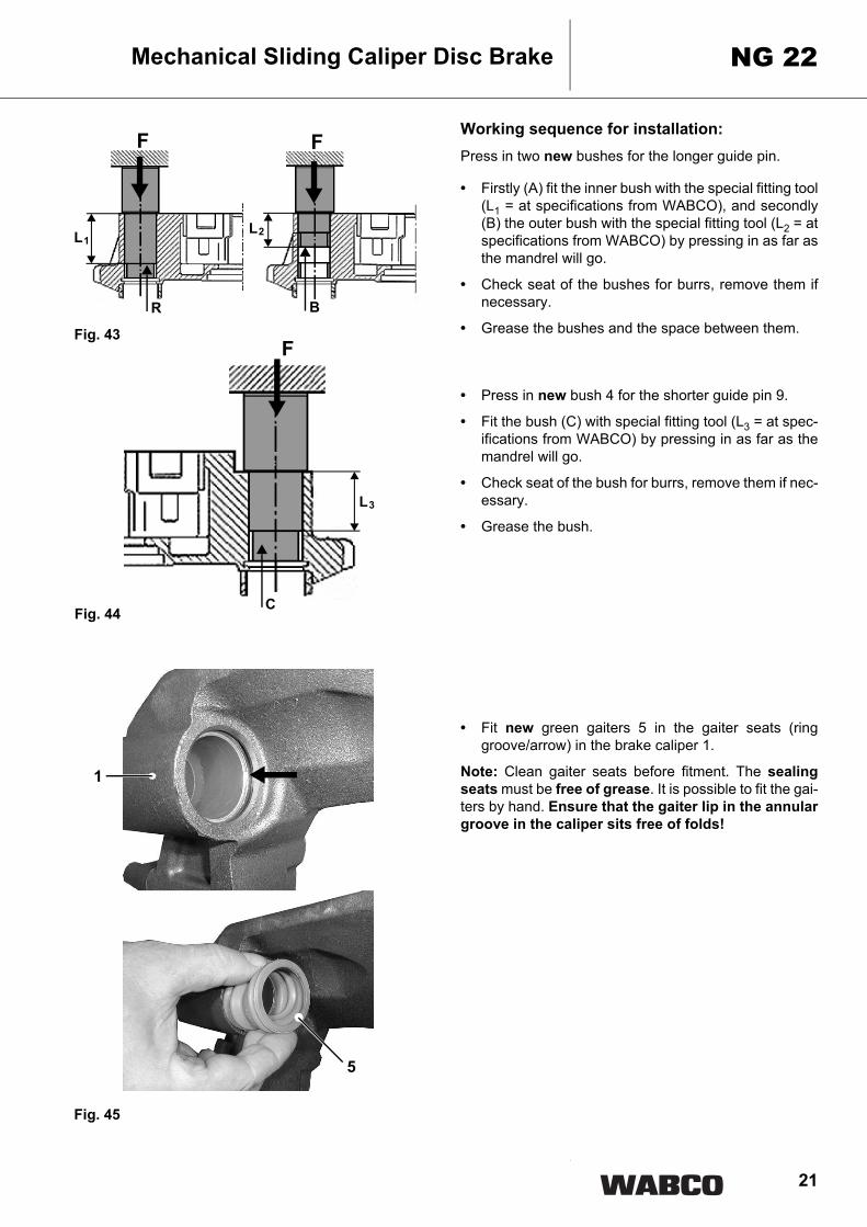
Working sequence for installation:Press in two new bushes for the longer guide pin.
• Firstly (A) fit the inner bush with the special fitting tool(L1 = at specifications from WABCO), and secondly(B) the outer bush with the special fitting tool (L2 = atspecifications from WABCO) by pressing in as far asthe mandrel will go.
• Check seat of the bushes for burrs, remove them ifnecessary.
• Grease the bushes and the space between them.
• Press in new bush 4 for the shorter guide pin 9.
• Fit the bush (C) with special fitting tool (L3 = at spec-ifications from WABCO) by pressing in as far as themandrel will go.
• Check seat of the bush for burrs, remove them if nec-essary.
• Grease the bush.
• Fit new green gaiters 5 in the gaiter seats (ringgroove/arrow) in the brake caliper 1.
Note: Clean gaiter seats before fitment. The sealingseats must be free of grease. It is possible to fit the gai-ters by hand. Ensure that the gaiter lip in the annulargroove in the caliper sits free of folds!
Mechanical Sliding Caliper Disc Brake NG 22
Fig. 44
Fig. 43
Fig. 45
F F
R
L1
B
L2
F
C
L3
1
5
22
Mechanical Sliding Caliper Disc BrakeNG 22
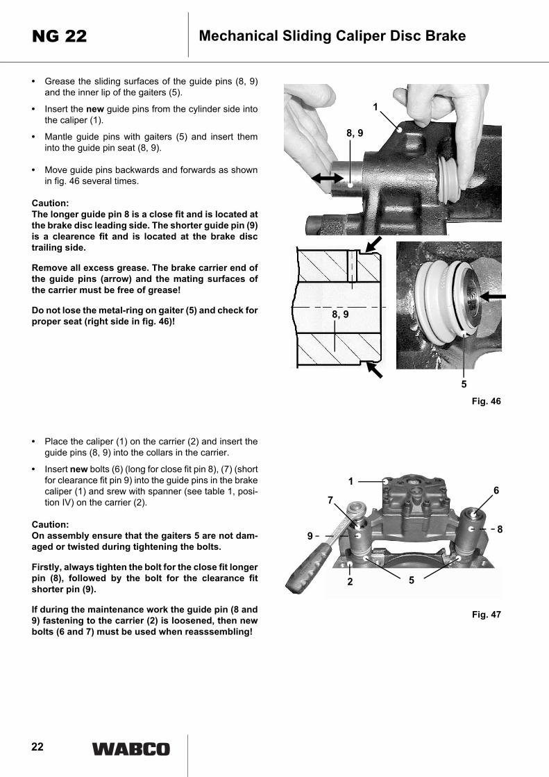
• Grease the sliding surfaces of the guide pins (8, 9)and the inner lip of the gaiters (5).
• Insert the new guide pins from the cylinder side intothe caliper (1).
• Mantle guide pins with gaiters (5) and insert theminto the guide pin seat (8, 9).
• Move guide pins backwards and forwards as shownin fig. 46 several times.
Caution: The longer guide pin 8 is a close fit and is located atthe brake disc leading side. The shorter guide pin (9)is a clearence fit and is located at the brake disctrailing side.
Remove all excess grease. The brake carrier end ofthe guide pins (arrow) and the mating surfaces ofthe carrier must be free of grease!
Do not lose the metal-ring on gaiter (5) and check forproper seat (right side in fig. 46)!
• Place the caliper (1) on the carrier (2) and insert theguide pins (8, 9) into the collars in the carrier.
• Insert new bolts (6) (long for close fit pin 8), (7) (shortfor clearance fit pin 9) into the guide pins in the brakecaliper (1) and srew with spanner (see table 1, posi-tion IV) on the carrier (2).
Caution: On assembly ensure that the gaiters 5 are not dam-aged or twisted during tightening the bolts.
Firstly, always tighten the bolt for the close fit longerpin (8), followed by the bolt for the clearance fitshorter pin (9).
If during the maintenance work the guide pin (8 and9) fastening to the carrier (2) is loosened, then newbolts (6 and 7) must be used when reasssembling!
Fig. 46
Fig. 47
8, 9
5
1
8, 9
8
1
9
52
76

23
• Move brake caliper backwards and forwards onguide pins (8, 9) several times. Check for ease ofmovement.
Caution: Do not squeeze the dust caps of the guide pinsagainst the brake carrier!
• Grease the bore holes for the covers (11) in the brakecalipers (1).
• Place new caps (11) in the bores in t he brake caliper1 and press home with a suitable tool.
Note: Take care to avoid damaging the covers.
• Mount brake over the brake disc on the axle accord-ing to section 4.
Note: Observe vehicle manufacturer's special assemblyinstructions when assembling brakes.
• Install brake pads and set clearence. Carry out ac-cording to section 3 and pay attention to notes.
• Before refitting the brake cylinder clean the sealingsurface on the caliper and grease the concave seat(arrow) in the brake lever.
• Refit the brake cylinder on the caliper according tosection 6.
Caution: With the brake cylinder in its installed position, en-sure that the lower drainage hole facing the groundis open! All other holes must be plugged!
Mechanical Sliding Caliper Disc Brake NG 22
Fig. 49
Fig. 48
9
8
1
1111
Fig. 53
FF

24
Mechanical Sliding Caliper Disc BrakeNG 22
5.2 Renewing adjuster screw gaiter
Note: If the gaiter only is to be renewed it is not neces-sary to dismantle the brake caliper and cylinder.
Working sequences for removal:• Remove brake pads and spreader plate according to
section 3.
• Pull brake caliper to actuation / cylinder side by hand.
• Pull the gaiter (10) out the annular groove in the ad-juster screw (21).
• Remove the gaiter from the seat in the brake caliperby means of a screwdriver.
• Check the adjuster screw thread (21).
Note: For this purpose refit the wheel side brake pad sothat the adjuster screw cannot be screwed completelyout of the adjuster. After the thread check remove thebrake pad.
Fig. 51
21
Fig. 52
10
Fig. 53
21

25
• Secure adjuster screw (21) against turning (arrowFig. 53) and screw out the adjuster screw c. 30 mmby turning the adjuster hexagon in the anti-clockwisedirection with a ring spanner.
• Examine the thread for corrosion and damage whilstscrewing out.
Caution: The gaiter (10) can be renewed, if definitely no dirt orwater has penetrated into the brake caliper, or if thegaiter has been directly damaged during servicingthe brake. In case of doubt the brake must be re-placed according to section 4, if internal parts arecorroded.
• After examination grease the thread and partly screwback the adjuster screw clockwise.
Working sequence for installation:• Clean the gaiter seat (10) (arrow) in the caliper.
• Push new gaiter (10) over the adjuster screw, centreit and push down the gaiter into the seat of the caliper(1) manually.
• Grease the gaiter lips (10) and insert the gaiter (10)into the seat of the adjuster screw (21).
Note: Ensure that the gaiter lip in the annular groove inthe adjuster screw sits free of folds!
• Install brake pads and set clearence. Carry out ac-cording to section 3 and pay attention to notes.
Mechanical Sliding Caliper Disc Brake NG 22
Fig. 55
Fig. 54
Fig. 56
Fig. 57
21
10
1
10
26
Mechanical Sliding Caliper Disc BrakeNG 22
6. Renewing brake cylinderAttention: Do not use a power-driven socket! Whileworking at the brake or moving the brakecaliper handle the caliper only from out-side to avoid injury!
Note: Only use cylinders as specified by vehicle manu-facturer. The following work sequences onla inform inprinciple about the assembly and disassembly of thebrake cylinder on the axles.
Detailed assembly and check instructions have to beused according to the cylilnder type and the instructionsof the cylinder manufacturer.
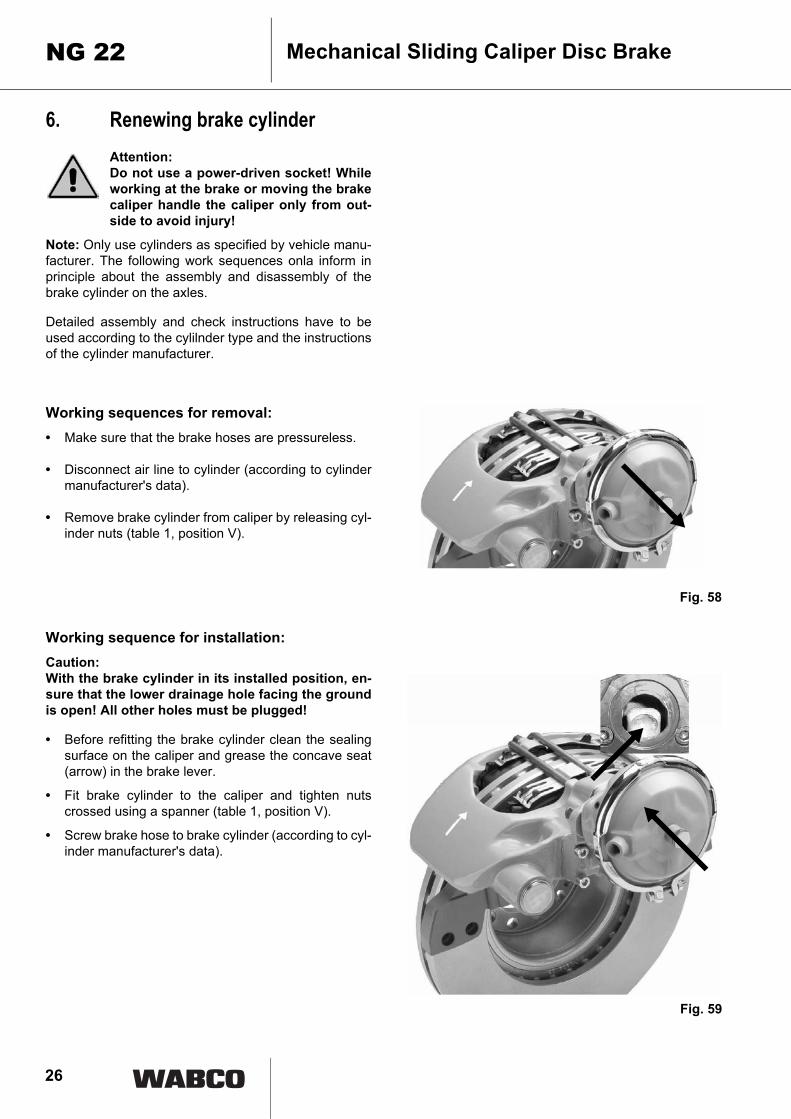
Working sequences for removal:• Make sure that the brake hoses are pressureless.
• Disconnect air line to cylinder (according to cylindermanufacturer's data).
• Remove brake cylinder from caliper by releasing cyl-inder nuts (table 1, position V).
Working sequence for installation:Caution: With the brake cylinder in its installed position, en-sure that the lower drainage hole facing the groundis open! All other holes must be plugged!
• Before refitting the brake cylinder clean the sealingsurface on the caliper and grease the concave seat(arrow) in the brake lever.
• Fit brake cylinder to the caliper and tighten nutscrossed using a spanner (table 1, position V).
• Screw brake hose to brake cylinder (according to cyl-inder manufacturer's data).
Fig. 58
Fig. 59

27
Note: The brake hose must not be twisted or locatedsuch that it will rub against anything! The brake hose ofthe air supply is not allowed to have an influence on themovability of the brake caliper.
• Test air connection for leaks (according to cylindermanufacturer's data).
• Carry out function and effectiveness check. Pay at-tention to the regulations of the cylinder manufactur-er!
Mechanical Sliding Caliper Disc Brake NG 22
Table 1: Tightening torques
Position Name Spanner width[AF]
hexagon Tightening torque:[Nm]External Internal
I Hexagon Adjuster 8 X –
Turning direction of the hexagon:• Adjust, anti-clockwise (left) maximum 3,
clearance decreases.
• De-adjust, clockwise (right), maximum 12, clearance increases.
Caution: Do not use a power-driven socket!
IIInternal hexagon bolt / Pad hold
down pin8 – X 30 + 15
III Brake fixation 27 X –
450 ± 30 recommended.Please pay attention to special assembly
instructions and if applicable to wrench size of the vehicle manufacturer!
IV Coupling guide pin 14 – X
310 ± 30Tightening order for guide pins:
1. Close fit pin (long internal hexagon bolt)2. Clearence fit pin (short internal hexagon bolt)
V Coupling brake cylinder 24 X –
210 - 30Please pay attention to special assembly
instructions and if applicable to wrench size of the cylinder manufacturer!
28
Mechanical Sliding Caliper Disc BrakeNG 22
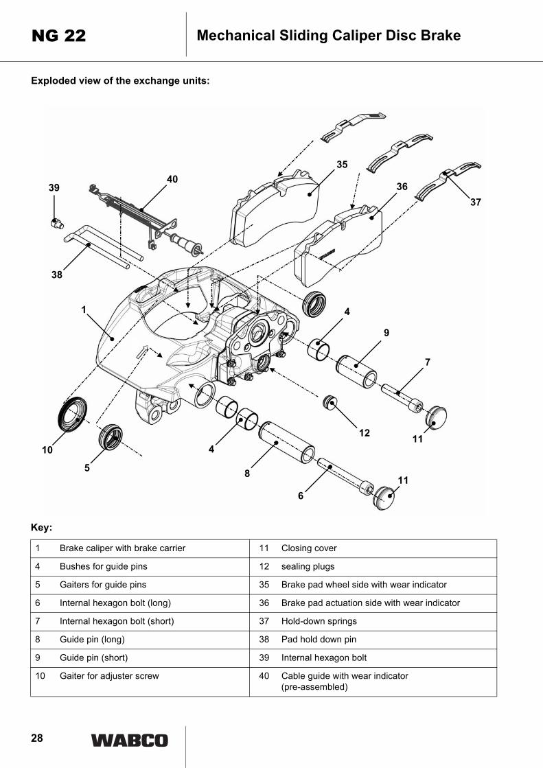
Exploded view of the exchange units:
1
40
38
39
35
3637
8
6
4
9
7
11
1210
5
11
4
Key:
1 Brake caliper with brake carrier 11 Closing cover
4 Bushes for guide pins 12 sealing plugs
5 Gaiters for guide pins 35 Brake pad wheel side with wear indicator
6 Internal hexagon bolt (long) 36 Brake pad actuation side with wear indicator
7 Internal hexagon bolt (short) 37 Hold-down springs
8 Guide pin (long) 38 Pad hold down pin
9 Guide pin (short) 39 Internal hexagon bolt
10 Gaiter for adjuster screw 40 Cable guide with wear indicator(pre-assembled)