Embed Size (px)
Citation preview

Operating Instructionsfor the WABCO Diagnostic Controller with Program Card ABS-Hydraulic446 300 782 0
WABCO


Operating Instructions
for the WABCO Diagnostic Controllerwith Program Card ABS-Hydr.446 300 782 0
Edition: March 1998
© Copyright WABCO 1998
WABCOFahrzeugbremsen
A Division ofWABCO Standard GmbH
The right of amendment is reserved

2
TABLE OF CONTENTSPage
1 Diagnostic Controller Set . . . . . . . . . . . . . . . . . . . . . . . . . . . . . . . . . . . . . . 31.1 General . . . . . . . . . . . . . . . . . . . . . . . . . . . . . . . . . . . . . . . . . . . . . . . . 41.2 Operation . . . . . . . . . . . . . . . . . . . . . . . . . . . . . . . . . . . . . . . . . . . . . . 4
2 What Systems Can Be Tested? . . . . . . . . . . . . . . . . . . . . . . . . . . . . . . . . . . 63 Connection of the Diagnostic Controller . . . . . . . . . . . . . . . . . . . . . . . . . . . 64 Program Structure . . . . . . . . . . . . . . . . . . . . . . . . . . . . . . . . . . . . . . . . . . . . 7
4.1 Diagnosis . . . . . . . . . . . . . . . . . . . . . . . . . . . . . . . . . . . . . . . . . . . . . . 84.1.1 Error Memory . . . . . . . . . . . . . . . . . . . . . . . . . . . . . . . . . . . . . . . 84.1.2 Component Actuate . . . . . . . . . . . . . . . . . . . . . . . . . . . . . . . . . . 84.1.3 Measured Values . . . . . . . . . . . . . . . . . . . . . . . . . . . . . . . . . . . . . 94.1.4 Controller data . . . . . . . . . . . . . . . . . . . . . . . . . . . . . . . . . . . . . . 9
4.2 System Check . . . . . . . . . . . . . . . . . . . . . . . . . . . . . . . . . . . . . . . . . . 94.3 Multimeter . . . . . . . . . . . . . . . . . . . . . . . . . . . . . . . . . . . . . . . . . . . . . 124.4 Options . . . . . . . . . . . . . . . . . . . . . . . . . . . . . . . . . . . . . . . . . . . . . . . 13
4.4.1 Online Help . . . . . . . . . . . . . . . . . . . . . . . . . . . . . . . . . . . . . . . 134.4.2 Version . . . . . . . . . . . . . . . . . . . . . . . . . . . . . . . . . . . . . . . . . . . 134.4.3 ECUs for Testing . . . . . . . . . . . . . . . . . . . . . . . . . . . . . . . . . . . 13
4.5 Special functions . . . . . . . . . . . . . . . . . . . . . . . . . . . . . . . . . . . . . . . 135 Functional Fault in Diagnostic System . . . . . . . . . . . . . . . . . . . . . . . . . . . 146 Pulse Program Sequence: Modulator Valves . . . . . . . . . . . . . . . . . . . . . 177 Plug Pin Assignment
ABS 446 044 07 . 0 . . . . . . . . . . . . . . . . . . . . . . . . . . . . . . . . . . . . . . 188 Connection Diagrams
ABS 446 044 07 . 0 . . . . . . . . . . . . . . . . . . . . . . . . . . . . . . . . . . . . . . 199 Test Log . . . . . . . . . . . . . . . . . . . . . . . . . . . . . . . . . . . . . . . . . . . . . . . . . . 20
LIST OF ABBREVIATIONS USED:
ABS Anti-Lock Braking SystemECU Electronic Control Unitel. electricallyHA rear axlehyd hydraulicle leftri rightVA front axle
3
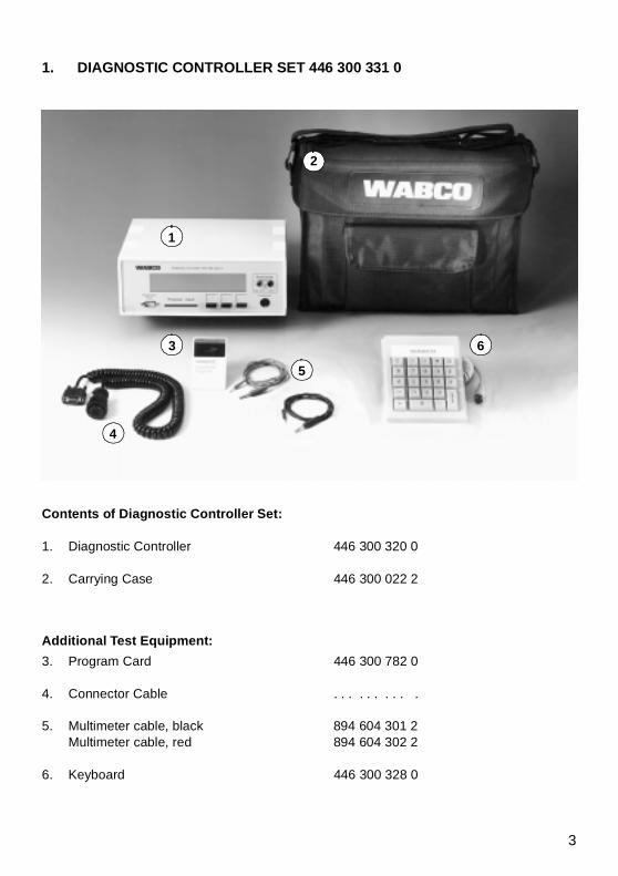
1. DIAGNOSTIC CONTROLLER SET 446 300 331 0
Contents of Diagnostic Controller Set:
1. Diagnostic Controller 446 300 320 0
2. Carrying Case 446 300 022 2
Additional Test Equipment:
3. Program Card 446 300 782 0
4. Connector Cable . . . . . . . . . .
5. Multimeter cable, black 894 604 301 2Multimeter cable, red 894 604 302 2
6. Keyboard 446 300 328 0
1
2
3
4
5
6
4
The DIAGNOSTIC-CONTROLLER
1.1 General
The Diagnostic Controller, referred to as the“Controller“ below, is a computer which iscapable of exchanging data with controlunits (which are computers, too). In thiscontext, data mean the following:
error messages stored in the ECU
commands sent from the Controller tothe ECU where they trigger certainprocesses.
In order to communicate with an ECU, aspecial program is required. This program isstored on the respective program card.
If an attempt is made to run an ECU with aprogram card which is not intended for it, theController will react by returning a messageto this effect.
*** Unknown control unit ***Diagnosis not possiblewith this program card !
CONTINUE
Any attempt to manipulate the connectedECU via the controller will be futile.
Program Card and ECU must match!
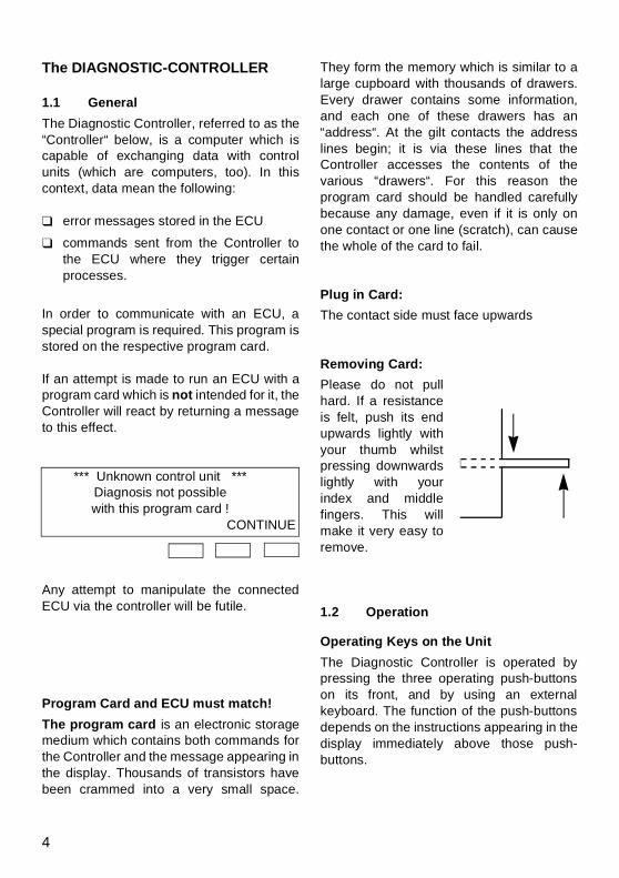
The program card is an electronic storagemedium which contains both commands forthe Controller and the message appearing inthe display. Thousands of transistors havebeen crammed into a very small space.
They form the memory which is similar to alarge cupboard with thousands of drawers.Every drawer contains some information,and each one of these drawers has an“address“. At the gilt contacts the addresslines begin; it is via these lines that theController accesses the contents of thevarious “drawers“. For this reason theprogram card should be handled carefullybecause any damage, even if it is only onone contact or one line (scratch), can causethe whole of the card to fail.
Plug in Card:
The contact side must face upwards
Removing Card:
Please do not pullhard. If a resistanceis felt, push its endupwards lightly withyour thumb whilstpressing downwardslightly with yourindex and middlefingers. This willmake it very easy toremove.
1.2 Operation
Operating Keys on the Unit
The Diagnostic Controller is operated bypressing the three operating push-buttonson its front, and by using an externalkeyboard. The function of the push-buttonsdepends on the instructions appearing in thedisplay immediately above those push-buttons.

5
1 Diagnosis 4 Options2 System check 5 Special functions3 MultimeterSelect function! EXIT Ò START
display instruction (function) push-buttons
Here are some examples for different push-button functions:
push-buttons function
START Initiate program
RETURN The display will return to the lastmain menu.
Ò Select an item from the main
menu.Scroll forward one item at a timeby pressing the push-button.The item selected will flash.
CONTINUE
The menu item selected istriggered, i. e. activated.
ABORT You have the option to abort thefunction in the event of an error
END Ending the function you havebeen working on, i. e. settingparameters.
CHANGE Changing the parametersappearing in the display.
COMPLETE
Confirms to the program that theprocess demanded by theoperator has been completed.
Operating the External Keyboard446 300 328 0
The external keyboard is recommendedbecause it makes operating the Controllervery simple.
Functions are only assigned to the markedkeys.
The keys can be usedinstead oft he three push-buttons on thediagnostic controller
Exception: if it is necessary to enter figuresduring the program, this function does notapply.
Using the ten-key block it is possible either to enter numerical data(for example ISO addresses) or to selectnumbered items from the main menu.
Using the key, the menu itemindicated is executed. The key has the samefunction as the controller key CONTINUE.
Using you can revert to the previousmain menu displayed.
Using , when there is a series of datadisplayed (eg., parameter, function test,calibration data), you can revert to theprevious display.
0
ENTER.
0 1 9to
ENTER
C
*

6
2. WHAT SYSTEMS CAN BETESTED?
This program card can be used to testcertain ABS-hydraulic systems which areidentified by the part number of the ABScontrol unit.
*) As per November ´97. Additional ECUsmay be suitable for testing. The program card won't realize any test
if it cannot identify the ECU.
system/plug 4-channel 6-channel
program card 446 300 782 0
ECUs which can be tested *)
446 044 071 0446 044 072 0
3. CONNECTING THE DIAGNOSTIC CONTROLLER
The Diagnostic Controller is connected tothe vehicle with a special cable (fromMERITOR WABCO):
Plug SUB DB9 Socket
+12 V Pin ? + 12 V Pin 1Ground Pin ? Ground Pin 2A-Line Pin ? A-Line Pin 6B-LIne Pin ? B-Line Pin 7
Connect the plug to the vehicle and the SUBDB9 socket to the Diagnostic Controller.This not only establishes the diagnosticconnection but also provides the voltagesupply. Black bars will appear in the display.
Now you push the program card into the slotprovided. Make sure that the contacts on thecard face upwards. You will now seesomething like this in the display:
ABS-HydraulicVersion 1.03 (English)
START
If this is not the case, please refer to Chapter5 on Functional Defects “DIAGNOSIS“. Thefirst display shows the system tested and theversion (in this case 1.03).

7
4. PROGRAME STRUCTURE
Menu Selection ABS Hydraulics
1 Diagnosis
1 Error memory
2 Component actuate
1 Warning lamp
2 Pump
3 Modulator valves
1 Front-right2 Front-left3 Rear-right4 Rear-left
4 Endurance brake *
3 Measured values
1 Voltages
2 Wheel speed
4 ECU parameters **
1 Reconfigure endurance brake relay
2 System check
3 Multimeter
1 Direct voltage (DC)
2 Alternating voltage (AC)
3 Resistance
4 Options
1 Online help
2 Version
3 Supported ECU’s
5 Special functions
* only if fitted on the vehicle** only available after entering the PIN
8
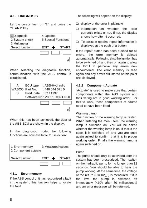
4.1. DIAGNOSIS
Let the cursor flash on “1“, and press the“START“ key.
1 Diagnosis 4 Options2 System check 5 Special Functions3 MultimeterSelect function! EXIT Ò START
G
When selecting the diagnostic function,communication with the ABS control isestablished.
A ECU type : ABS-HydraulicWABCO Part No. : 446 044 071 0
S Prod. date : 32 / 1997Software No.: V8551 CONTINUE
G
When this has been achieved, the data ofthe ABS ECU are shown in the display.
In the diagnostic mode, the followingfunctions are now available for selection:
1 Error memory 3 Measured values2 Component actuate
Select function! EXIT Ò START
4.1.1 Error memory
If the ABS control unit has recognized a faultin the system, this function helps to locatethe fault
The following will appear on the display:
display of the error in plaintext
information on whether the errorcurrently exists or not. If not, the displayshows how often it occurred.
To assist in repairs, repair information isdisplayed at the push of a button
If the repair button has been pushed for allerrors, the error memory is deletedautomatically. Following this, the ignition hasto be switched off and then on again to allowthe ECU to perceive any errors nowencountered. The error memory is readagain and any errors still stored at this pointare displayed.
4.1.2 Component Actuate
“Actuate“ is used to make sure that certaincomponents within the ABS system andtheir wiring are in good working order. Forthis to work, those components of courseneed to have been fitted
Warning LampThe function of the warning lamp is tested.When entering the menu item, the warninglamp is switched on. You will be askedwhether the warning lamp is on. If this is thecase, it is switched off and you are onceagain asked to confirm that it is in properworking order. Finally the warning lamp isagain switched on.
PumpThe pump should only be activated after thesystem has been pressurized. Then switchon the hydraulic pump for no longer than 12seconds. You should be able to hear thepump working. At the same time, the voltageat the return (Pin X2_8) is measured. If it istoo low, the pump is switched offimmediately (<10V after 30 milliseconds)and an error message will be returned.

9
Solenoid ValvesA pulse programme can be used to makesure the solenoid valves and their wiring(hydraulic and electrical) are in properworking order, and that the allocation to allfour ABS valves is correct. For the pressure curve, please refer to thediagram on Page 17.
Retarder RelayThe relay for switching off the retarderfunction in the event of ABS interventionduring the braking process can be actuated.It is switched on for the length of time thepush-button is depressed, i. e. the contactswill open. The moment the retarder relay isactuated, the braking force must fall sincethe retarder no longer affects the brakingprocess. This menu item is displayed only ifa retarder relay has been fitted.
4.1.3 Measuring Values
In this part of the program, variousmeasuring values provided by the ECU canbe displayed.
VoltagesThe ignition voltage (X2_2) and the valverelay voltage (internal) are displaced.
Wheel SpeedsAll four wheel speeds picked up by thespeed sensors (mph) are output in awindow. They will not be displayed until aspeed of 1.1 mph has been reached.
4.1.4 Control Unit Data
Reconfiguration of Retarder RelayWhen it is first put into operation(commissioning), the ECU will checkwhether a retarder relay has beenconnected at its terminals. If this is the case,the relay is entered in the parameters as
having been fitted. If, at a later point in time,no relay is connected, the ECU will perceivean error. This menu item can be used toonce again achieve automatic recognition(reconfiguration). This item is available onlywhen a PIN has been entered.
4.2. SYSTEM CHECK
System check permits a complete ABS testincluding print-out of a test log (e.g. after firstinstallation or after extensive repairs).
System check is divided into 2 sections:
functional test
print results
Important notes:Once a test section has been initiated, thishas to be processed step by step. It isneither possible to return to individual stepsnor to leave them out.
If the supply voltage to the DiagnosticController is interrupted, all data measuredand stored for the print log up to that point oftime are destroyed. Thus it is important thatthe supply to the Diagnostic Controller is notinterrupted if a print log is required.
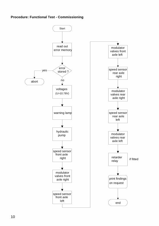
Functional Test
The functional test can be used only whilethe vehicle is stationary (in current ignition-on phase, its wheels may not simultaneouslyhave exceeded a speed of 4.35 mph), and ifno errors have been stored.
10
Procedure: Functional Test - Commissioning
Fehlerspeicherauslesen
Spannungen(U>10.78V)
Warnlampe
Drehzahl-sensor VA
rechts
Modulator-ventile VA
rechts
Drehzahl-sensor VA
links
Modulator-ventile VA
links
Drehzahl-sensor HA
links
Modulator-ventile HA
links
Bei BedarfAusdruck derErgebnisse
Hydraulik-Pumpe
Drehzahl-sensor HA
rechts
Modulator-ventile HA
rechts
Fehler gesp. ?
Abbruch
Ende
Retarder-Relais
wennverbaut
Start
Ja
Nein
read outerror memory
error stored ?
no
yes
abort
voltages
warning lamp
hydraulicpump
speed sensorfront axle
right
modulator valves front
axle right
speed sensorfront axle
left
speed sensorrear axle
right
speed sensorrear axle
left
modulator valves front
axle left
modulator valves rear
axle right
modulator valves rear
axle left
retarder relay
print findings on request
if fitted
end
11
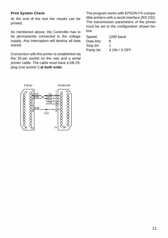
Print System Check
At the end of the test the results can beprinted.
As mentioned above, the Controller has tobe permanently connected to the voltagesupply. Any interruption will destroy all datastored.
Connection with the printer is established viathe 25-pin socket on the rear and a serialprinter cable. The cable must have a DB 25-plug (not socket !) at both ends.
The program works with EPSON FX-compa-tible printers with a serial interface (RS 232).The transmission parameters of the printermust be set to the configuration shown be-low:
Speed: 1200 baudData bits: 8Stop bit: 1Parity bit: X ON / X OFF
12
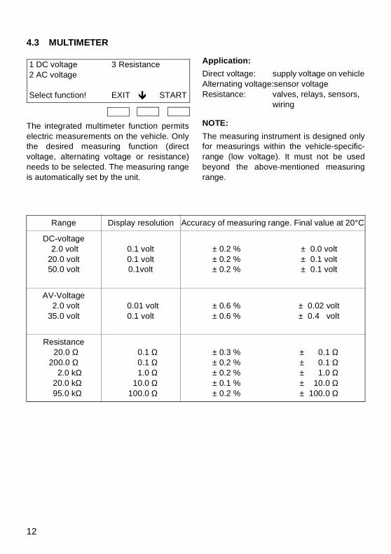
4.3 MULTIMETER
1 DC voltage 3 Resistance2 AC voltage
Select function! EXIT Ò START
The integrated multimeter function permitselectric measurements on the vehicle. Onlythe desired measuring function (directvoltage, alternating voltage or resistance)needs to be selected. The measuring rangeis automatically set by the unit.
Application:
Direct voltage: supply voltage on vehicleAlternating voltage:sensor voltageResistance: valves, relays, sensors,
wiring
NOTE:
The measuring instrument is designed onlyfor measurings within the vehicle-specific-range (low voltage). It must not be usedbeyond the above-mentioned measuringrange.
Range Display resolution Accuracy of measuring range. Final value at 20°C
DC-voltage 2.0 volt20.0 volt50.0 volt
0.1 volt0.1 volt0.1volt
± 0.2 %± 0.2 %± 0.2 %
± 0.0 volt± 0.1 volt± 0.1 volt
AV-Voltage 2.0 volt35.0 volt
0.01 volt0.1 volt
± 0.6 %± 0.6 %
± 0.02 volt± 0.4 volt
Resistance 20.0 Ω200.0 Ω
2.0 kΩ 20.0 kΩ 95.0 kΩ
0.1 Ω 0.1 Ω 1.0 Ω 10.0 Ω 100.0 Ω
± 0.3 %± 0.2 %± 0.2 %± 0.1 %± 0.2 %
± 0.1 Ω± 0.1 Ω± 1.0 Ω± 10.0 Ω± 100.0 Ω
13
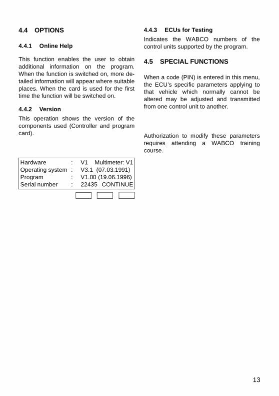
4.4 OPTIONS
4.4.1 Online Help
This function enables the user to obtainadditional information on the program.When the function is switched on, more de-tailed information will appear where suitableplaces. When the card is used for the firsttime the function will be switched on.
4.4.2 Version
This operation shows the version of thecomponents used (Controller and programcard).
Hardware : V1 Multimeter: V1Operating system : V3.1 (07.03.1991)Program : V1.00 (19.06.1996)Serial number : 22435 CONTINUE
4.4.3 ECUs for Testing
Indicates the WABCO numbers of thecontrol units supported by the program.
4.5 SPECIAL FUNCTIONS
When a code (PIN) is entered in this menu,the ECU’s specific parameters applying tothat vehicle which normally cannot bealtered may be adjusted and transmittedfrom one control unit to another.
Authorization to modify these parametersrequires attending a WABCO trainingcourse.

14
5. FUNCTIONAL FAULT IN DIAGNOSTIC SYSTEM
no display
black „bars“
*** LOW VOLTAGE ***
CONT.
Cause Remedy
– no voltage supply
– undervoltage (less than about 7 volts)
– check all plugged connections
– check supply voltage
Cause Remedy
– program card not inserted – push program card in as far as the stop (Kontakte nach oben).
Cause Remedy
– Supply voltage too low (only during diagnostic operation)
– check battery load capacity, and ensure adequate supply.
15
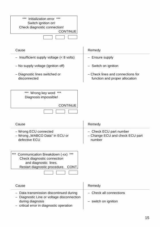
*** Initialization error ***Switch ignition on!
Check diagnostic connection!CONTINUE
*** Wrong key word ***Diagnosis impossible!
CONTINUE
*** Communication Breakdown (-xx) ***Check diagnostic connection
and diagnostic lines. Restart diagnostic procedure. CONT.
Cause Remedy
– Insufficient supply voltage (< 8 volts)
– No supply voltage (ignition off)
– Diagnostic lines switched or disconnected
– Ensure supply
– Switch on ignition
– Check lines and connections for function and proper allocation
Cause Remedy
– Wrong ECU connected– Wrong „WABCO Data“ in ECU or defective ECU
– Check ECU part number– Change ECU and check ECU part number
Cause Remedy
– Data transmission discontinued during– Diagnostic Line or voltage disconnection during diagnosis– critical error in diagnostic operation
– Check all connections
– switch on ignition

16
*** Unknown control unit ***Diagnosis not possiblewith this program card!
CONTINUE
*** Error during self-test ***EEPROM of Diagnostic Controller
faultyCONTINUE
Cause Remedy
– ECU cannot be tested with this program card
– Use right program card
Cause Remedy
– EEPROM (Diagnostic Controller's) non-volatile memory of DC defective
– Repair Diagnostic Controller
17
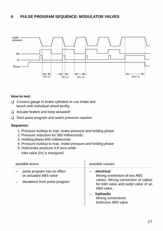
6 PULSE PROGRAM SEQUENCE: MODULATOR VALVES
How to test:
Connect gauge to brake cylinders or use brake test bench with individual wheel facility.
Actuate brakes and keep actuated!
Start pulse program and watch pressure reaction.
Sequence:
1. Pressure buildup to max. brake pressure and holding phase2. Pressure reduction for 360 milliseconds3. Holding phase 840 milliseconds4. Pressure buildup to max. brake pressure and holding phase5. Hold brake pressure 4.8 secs while
inlet valve (IV) is energized
possible errors possible causes
– pulse program has no effect on actuated ABS valve
– deviations from pulse program
– electrical Wrong connection of two ABS valves. Wrong connection of cablesfor inlet valve and outlet valve of anABS valve.
– hydraulic Wrong connectionsDefective ABS valve
18
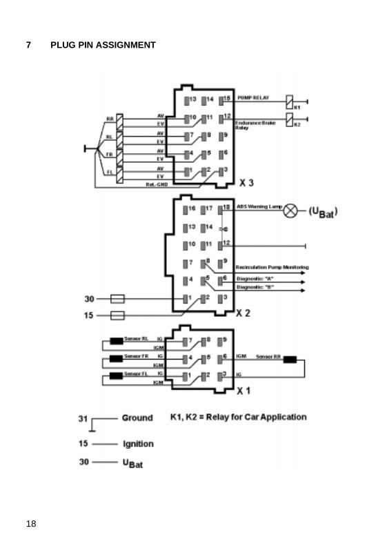
7 PLUG PIN ASSIGNMENT
19
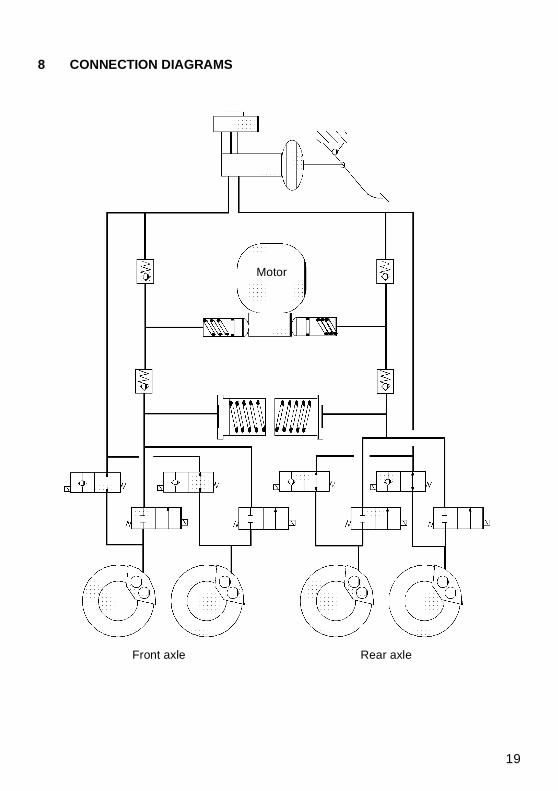
8 CONNECTION DIAGRAMS
Front axle Rear axle
Motor
20
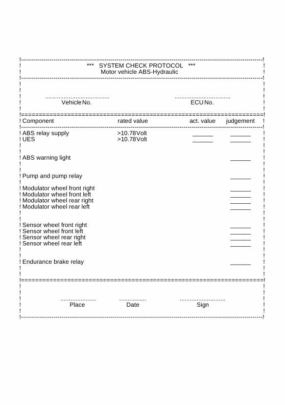
9 TEST LOG
The printed commissioning log shows amaximum version to be copied for operationwhere there is no printer available. Thecorresponding findings of the various stepswithin the testing procedure are enteredfrom the commissioning run.
21
!-----------------------------------------------------------------------------------------------------------------------!! *** SYSTEM CHECK PROTOCOL *** !! Motor vehicle ABS-Hydraulic !!-----------------------------------------------------------------------------------------------------------------------!! !! !! ...................................... ................................. !! Vehicle No. ECU No. !! !!====================================================================!! Component rated value act. value judgement !!-----------------------------------------------------------------------------------------------------------------------!! ABS relay supply >10.78 Volt ______ ______ !! UES >10.78 Volt ______ ______ !! !! !! ABS warning light ______ !! !! !! Pump and pump relay ______ !! !! Modulator wheel front right ______ !! Modulator wheel front left ______ !! Modulator wheel rear right ______ !! Modulator wheel rear left ______ !! !! !! Sensor wheel front right ______ !! Sensor wheel front left ______ !! Sensor wheel rear right ______ !! Sensor wheel rear left ______ !! !! !! Endurance brake relay ______ !! !! !!====================================================================!! !! !! ..................... ................ ........................... !! Place Date Sign !! !!-----------------------------------------------------------------------------------------------------------------------!

22
Cop
yrig
ht: W
AB
CO
´98
. Prin
ted
in G
erm
any.
No
part
of t
his
publ
icat
ion
may
be
repr
oduc
ed w
ithou
t our
prio
r pe
rmis
sion
. The
rig
ht o
f am
endm
ent i
s re
serv
ed. W
abco
druc
k 81
5 00
0 26
7 3/
03.9
8
WABCOFahrzeugbremsenA Division ofWABCO Standard GmbH
Am Lindener Hafen 2130453 HannoverTelefon (05 11) 9 22-0Telefax (05 11) 2 10 23 57
WABCO