Embed Size (px)
Citation preview

ASSEMBLY, INSTALLATION, AND REMOVAL OF CONTACTS AND MODULESFOR HIGH POWER CONTACTS AND MODULES
Table of Contents
SECTION 1 RECEIVER CONTACT ASSEMBLY INSTRUCTIONS
SECTION 2 ITA CONTACT ASSEMBLY INSTRUCTIONS
SECTION 3 CONTACT INSTALLATION AND REMOVAL INSTRUCTIONS
SECTION 4 MODULE INSTALLATION AND REMOVAL INSTRUCTIONS
SECTION 5 ITA CABLE ASSEMBLY INSTRUCTIONS
SECTION 6 HIGH POWER ACCESSORIES
SECTION 7 CROSS REFERENCE TABLES
APPENDIX PRODUCT PERFORMANCE SPECIFICATIONS
5/9/2017
Please note that any printed or downloaded User Manuals or Procedure Sheets may not reflect the most current revisions. The information contained in these materials is subject to change.
For the most current information available, visit www.vpc.com.

HIGH POWER CONTACTS AND MODULES USER’S MANUAL: SECTION 1 VIRGINIA PANEL CORPORATION
1-1 For the most current information available, visit www.vpc.com. 5/9/2017
TOOLS REQUIREDWire CutterJacket StripperPneumatic Crimp Tool Kit, Part # 910 102 116, (Figure A) includes: • High Power Pneumatic Crimper • High Power Contact Locator • High Power Contact Die SetPoint MicrometerHeat Gun
CRIMP TOOL SETUP1. Disconnect airline.
2. Install locator into locator cavity (Figure B).
3. Install die set into pneumatic crimper (Figure B).
4. Ensure front plate is installed on crimper (Figure A).
5. Re-connect airline.
ASSEMBLY INSTRUCTIONS1. Cut wire to length.
2. Strip wire 0.75" (19.05 mm).
3. Carefully insert wire into the wire end of the contact. NOTE: Be careful not to disturb the natural lay of the individual wire strands,
this could make it difficult to insert the strands into the contact.
4. Place the contact into the crimper cavity until it completely bottoms out against the end of the locator.
5. Depress button to crimp and then remove the crimped wire and contact from the crimp cavity (Figure C).
6. Inspect the location of crimp indentions. Indentions should be located between the wire end of the crimp barrel and the wire inspection hole. The wire should be visible in the inspection hole (Figure C).
7. Use a point micrometer to measure the crimp height across the crimp indentions. Measure across the crimp indentions, rotate the contact 90° and measure across remaining crimp indentions. The measurement should be 0.279" ± 0.005" [7.087 ± 0.127 mm] (Figure D).
8. Slide a 2" piece of Ø0.5" shrink tubing over the contact up to the first shoulder from the wire end of the contact covering the inspection hole and shrink in place with heat gun (Figure E).
HIGH POWER RECEIVER CONTACT ASSEMBLYPART # 610 149 101, 610 150 101
NOTE: Contact tested and designed for specific use with Cooner Wire CW6044-14(UL Rated), AS 105-14(Non-UL), or equivalent. If using a wire other than prescribed, reference “5.3.5 Machined Contacts - CMA buildup” of the IPC/WHMA-A-620A standard.
NOTE: Recommended CMA range for this contact falls between 63,206 and 66,499 with a max conductor Ø of .340" [8.636 mm] and a min conductor Ø of .315" [8.001 mm]. To calculate CMA please reference Figure F.
Figure C1. 610 149 101 contact.
Figure E. Applied shrink tubing.
Figure D. Measuring crimp.
HIGH POWER PNEUMATIC CRIMPER
HIGH POWER CONTACT LOCATOR
HIGH POWER CONTACT DIE SET
Figure B. Exploded view of pneumatic crimper.
Figure A. Pneumatic crimper.
FRONT PLATE
INSPECTION HOLE
D
Number ofStrands
Stranded Wire AWG
Metric DimensionsCMA = D2 x N x 1550.003
CMA = Circular Mil AreaD = Diameter of Single Strand
N = Number of Strandsin millimeters
D
U.S. Customary DimensionsCMA = D2 x N
CMA = Circular Mil AreaD = Diameter of Single Strand
N = Number of Strandsin mils
Figure F. Calculate circular mil area.
Figure C2. 610 150 101 contact.

HIGH POWER CONTACTS AND MODULES USER’S MANUAL: SECTION 2 VIRGINIA PANEL CORPORATION
2-1
For the most current information available, visit www.vpc.com. 5/9/2017
HIGH POWER ITA CONTACT ASSEMBLYPART # 610 150 101
TOOLS REQUIREDWire CutterJacket StripperPneumatic Crimp Tool Kit, Part # 910 102 116, (Figure A) includes: • High Power Pneumatic Crimper • High Power Contact Locator • High Power Contact Die SetPoint MicrometerHeat Gun
CRIMP TOOL SETUP1. Disconnect airline.
2. Install locator into locator cavity (Figure B).
3. Install die set into pneumatic crimper (Figure B).
4. Ensure front plate is installed on crimper (Figure A).
5. Re-connect airline.
ASSEMBLY INSTRUCTIONS
1. Cut wire to length.
2. Strip wire 0.75" (19.05 mm).
3. Carefully insert wire into the wire end of the contact. NOTE: Be careful not to disturb the natural lay of the individual wire strands,
this could make it difficult to insert the strands into the contact.
4. Place the contact into the crimper cavity until it completely bottoms out against the end of the locator.
5. Depress button to crimp and then remove the crimped wire and contact from the crimp cavity (Figure C).
6. Inspect the location of crimp indentions. Indentions should be located between the wire end of the crimp barrel and the wire inspection hole. The wire should be visible in the inspection hole (Figure C).
7. Use a point micrometer to measure the crimp height across the crimp indentions. Measure across the crimp indentions, rotate the contact 90° and measure across remaining crimp indentions. The measurement should be 0.279" ± 0.005" [7.087 ± 0.127 mm] (Figure D).
8. Slide a 2" piece of Ø0.5" shrink tubing over the contact up to the first shoulder from the wire end of the contact covering the inspection hole and shrink in place with heat gun (Figure E).
NOTE: Contact tested and designed for specific use with Cooner Wire CW6044-14(UL Rated), AS 105-14(Non-UL), or equivalent. If using a wire other than prescribed, reference “5.3.5 Machined Contacts - CMA buildup” of the IPC/WHMA-A-620A standard.
NOTE: Recommended CMA range for this contact falls between 63,206 and 66,499 with a max conductor Ø of .340" [8.636 mm] and a min conductor Ø of .315" [8.001 mm]. To calculate CMA please reference Figure F.
Figure B. Exploded view of pneumatic crimper.
Figure C. Crimped contact.
Figure D. Measuring crimp.
Figure E. Applied shrink tube.
High Power Pneumatic Crimper
High Power Contact Locator
High Power Contact Die Set
Figure A. Pneumatic crimper.
FRONT PLATE
D
Number ofStrands
Stranded Wire AWG
Metric DimensionsCMA = D2 x N x 1550.003
CMA = Circular Mil AreaD = Diameter of Single Strand
N = Number of Strandsin millimeters
D
U.S. Customary DimensionsCMA = D2 x N
CMA = Circular Mil AreaD = Diameter of Single Strand
N = Number of Strandsin mils
Figure F. Calculate circular mil area.
INSPECTION HOLE

HIGH POWER CONTACTS AND MODULES USER’S MANUAL: SECTION 3 VIRGINIA PANEL CORPORATION
3-1 5/9/2017 For the most current information available, visit www.vpc.com.
Figure B. Fully seat extraction tool before depressing.
HIGH POWER RECEIVER CONTACT
A
DETAIL A
RETAINING RING TAB
HIGH POWER 90 SERIES RECEIVER CONTACT INSTALLATION AND REMOVALPART # 510 104 307
Figure A. Separating the module.
TOOLS REQUIREDPhillips Head ScrewdriverHigh Power Receiver/ITA Contact Extraction Tool, Part # 910 112 129In/Lbs Torque Driver
CONTACT INSTALLATION INSTRUCTIONS1. Assemble the contact to the respective wire. NOTE: Contact tested and designed for specific use with 2 AWG
Cooner Wire CW6044-14(UL Rated), AS 105-14(Non-UL), or equivalent. NOTE: For more information concerning the contact assembly
process, please see contact assembly instructions in Section 1 of this User’s Manual.
2. Insert the assembled contact into the back (wiring side) of the assembled module. Once in place, pull the wire slightly to ensure that the contact is fully seated.
3. Install strain relief plate and secure wires to strain relief. NOTE: In all High Power contact applications, VPC highly
recommends the use of a strain relief plate.
CONTACT REMOVAL INSTRUCTIONS1. Remove the module from the receiver frame. NOTE: For more information concerning the process of removing the module from the receiver frame, see module installation and removal instructions in Section 4 of this User’s Manual.
2. Use a Phillips head screwdriver to remove the screws located at the top and bottom of the module.
3. Grasp the module halves and apply force in opposite directions, rocking the ends of the module while slightly pulling the top of the module away from the mating bottom section, until separated
(Figure A).
4. Place the High Power Receiver/ITA Contact Extraction Tool, Part # 910 112 129 (Figure B), over the contact to be removed/ replaced. Use care to keep the tool perpendicular to the surface of the module, otherwise the tool or contact could be damaged. Rotate the tool slightly while pushing it into the counter
bore on the mating side of the module.
5. Once the extraction tool is seated and the retaining tabs on the retaining ring are compressed (Figure B), push the tool into the
module. The contact will be pushed out of the rear of the module.
DO NOT PUSH THE TOOL INTO THE MODULE UNTILTHE TIP OF THE EXTRACTION TOOL HAS FULLY SEATED INTO THE MODULE AND COMPRESSED THE RETAINING RING TABS ON THE CONTACT.
6. If necessary, replace the module cap using both hands to push the separated halves together. Replace and tighten the module retaining screws to a maximum torque of 1.5 in-lbs [0.17 Nm].
EXTRACTION TOOLPART # 910 112 129

HIGH POWER CONTACTS AND MODULES USER’S MANUAL: SECTION 3 VIRGINIA PANEL CORPORATION
3-2 5/9/2017 For the most current information available, visit www.vpc.com.
HIGH POWER iCON/i1 RECEIVER CONTACT INSTALLATION AND REMOVALPART # 510 160 124
TOOLS REQUIREDFlat Head ScrewdriverPhillips Head ScrewdriverHigh Power Receiver/ITA Contact Extraction Tool, Part # 910 112 129In/Lbs Torque Driver
CONTACT INSTALLATION/LOADING INSTRUCTIONS1. Assemble the contact to the respective wire. NOTE: Contact tested and designed for specific use with 2 AWG Cooner Wire
CW6044-14(UL Rated), AS 105-14(Non-UL), or equivalent. NOTE: For more information concerning the contact assembly process, please see contact assembly instructions in Section 1 of this User’s Manual.
2. Ensure empty modules are secure in receiver frame. Insert the assembled contact into the back (wiring side) of the assembled module. Once in place, pull the wire slightly to ensure that the contact is fully seated.
NOTE: For more information concerning the module installation process, please see iCon module installation and removal instructions in Section 4 of this User’s Manual.
3. If loading an iCon frame, repeat steps 1 and 2 for module “A”, loading High Power contacts in positions 3 and 4 only (All TriPaddle positions may be used).
4. Install strain relief plate and secure wires to strain relief. NOTE: In all High Power contact applications, VPC highly recommends the
use of a strain relief plate.
CONTACT REMOVAL INSTRUCTIONS1. Remove the module from the receiver frame. NOTE: For more information concerning the process of removing the module from
the receiver frame, see module installation and removal instructions in Section 4 of this User’s Manual.
2. Use a Phillips head screwdriver to remove the screws located at the top and bottom of the module.
3. Grasp the module halves and apply force in opposite directions, rocking the ends of the module while slightly pulling the top of the module away from the mating bottom section, until separated. You may pry at the machined slot on the module using a flat head screwdriver to assist in opening the module. Be sure to open both sides of the module simultaneously or contacts could be damaged.
4. Place the High Power Receiver/ITA Contact Extraction Tool, Part # 910 112 129 (Figure C), over the contact to be removed/ replaced. Use care to keep the tool perpendicular to the surface of the module, otherwise the tool or contact could be damaged. Rotate the tool slightly while pushing it into the counter bore on the mating side of the module.
5. Once the extraction tool is seated and the retaining tabs on the retaining ring are compressed (Figure C), push the tool into the module. The contact will be pushed out of the rear of the module.
DO NOT PUSH THE TOOL INTO THE MODULE UNTIL THE TIP OF THE EXTRACTION TOOL HAS FULLY SEATED INTO THE MODULE AND COMPRESSED THE RETAINING RING TABS ON THE CONTACT
6. If necessary, replace the module cap using both hands to push the separated halves together. Replace and tighten the module retaining screws to a maximum torque of 1.5 in-lbs [0.17 Nm].
Figure C. Fully seat extraction tool before depressing.
A
Figure B. Correctly loaded receiver contacts in iCon.
Figure A. Correctly loaded receiver contacts in i1.
DETAIL A
“B”or
BOTTOMPOSITION
“A”or
TOPPOSITION
EXTRACTION TOOLPART # 910 112 129
HIGH POWERRECEIVER CONTACT
RETAINING RING TAB

HIGH POWER CONTACTS AND MODULES USER’S MANUAL: SECTION 3 VIRGINIA PANEL CORPORATION
3-3 5/9/2017 For the most current information available, visit www.vpc.com.
TOOLS REQUIREDPhillips Head ScrewdriverHigh Power Receiver/ITA Contact Extraction Tool, Part # 910 112 129In/Lbs Torque Driver
CONTACT INSTALLATION INSTRUCTIONS1. Assemble the contact to the respective wire. NOTE: Contact tested and designed for specific use with 2 AWG
Cooner Wire CW6044-14(UL Rated), AS 105-14(Non-UL), or equivalent. NOTE: For more information concerning the contact assembly
process, please see contact assembly instructions in Section 2 of this User’s Manual.
2. Insert the assembled contact into the back (wiring side) of the assembled module. Once in place, pull the wire slightly to ensure that the contact is fully seated.
3. Install strain relief plate and secure wires to strain relief. NOTE: In all High Power contact applications, VPC highly
recommends the use of a strain relief plate.
CONTACT REMOVAL INSTRUCTIONS1. Remove the module from the ITA frame. NOTE: Prior to extracting contacts, wire must be untied from the strain
relief. NOTE: For more information concerning the process of removing the
module from the ITA frame, see module installation and removal instructions in Section 4 of this User’s Manual.
2. Use a Phillips head screwdriver to remove the screws located at the top and bottom of the module.
3. Grasp the module halves and apply force in opposite directions, rocking the ends of the module while slightly pulling the top of the module away from the mating bottom section, until separated. Be sure to open both sides of the module simultaneously or contacts could be damaged (Figure A).
4. Place the High Power Receiver/ITA Contact Extraction Tool, Part # 910 112 129 (Figure B), over the contact to be removed/ replaced. Use care to keep the tool perpendicular to the surface of the module, otherwise the tool or contact could be damaged. Rotate the tool slightly while pushing it into the counter bore on the mating side of the module.
5. Once the extraction tool is seated and the retaining tabs on the retaining ring are compressed (Figure B), push the tool into the module. The contact will be pushed out of the rear of the module.
DO NOT PUSH THE TOOL INTO THE MODULE UNTIL THE TIP OF THE EXTRACTION TOOL HAS FULLY SEATED INTO THE MODULE AND COMPRESSED THE RETAINING RING TABS ON THE CONTACT
6. If necessary, replace the module cap using both hands to push the separated halves together. Replace and tighten the module retaining screws to a maximum torque of 1.5 in-lbs [0.17 Nm].
HIGH POWER 90 SERIES ITA CONTACT INSTALLATION AND REMOVALPART # 510 108 281
Figure A. Separating the module.
Figure B. Fully seat extraction tool before depressing.
HIGH POWER ITA CONTACT
A
DETAIL AEXTRACTION TOOLPART # 910 112 129
RETAINING RING TAB
HIGH POWER CONTACTS AND MODULES USER’S MANUAL: SECTION 3 VIRGINIA PANEL CORPORATION
3-4 5/9/2017 For the most current information available, visit www.vpc.com.
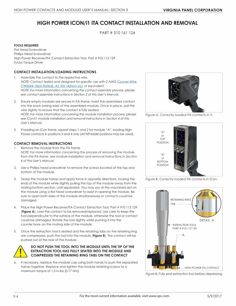
HIGH POWER iCON/i1 ITA CONTACT INSTALLATION AND REMOVALPART # 510 161 124
TOOLS REQUIREDFlat Head ScrewdriverPhillips Head ScrewdriverHigh Power Receiver/ITA Contact Extraction Tool, Part # 910 112 129In/Lbs Torque Driver
CONTACT INSTALLATION/LOADING INSTRUCTIONS1. Assemble the contact to the respective wire. NOTE: Contact tested and designed for specific use with 2 AWG Cooner Wire
CW6044-14(UL Rated), AS 105-14(Non-UL), or equivalent. NOTE: For more information concerning the contact assembly process, please
see contact assembly instructions in Section 2 of this User’s Manual.
2. Ensure empty modules are secure in ITA frame. Insert the assembled contact into the back (wiring side) of the assembled module. Once in place, pull the wire slightly to ensure that the contact is fully seated.
NOTE: For more information concerning the module installation process, please see iCon/i1 module installation and removal instructions in Section 4 of this User’s Manual.
3. If loading an iCon frame, repeat steps 1 and 2 for module “A”, loading High Power contacts in positions 3 and 4 only (All TriPaddle positions may be used).
CONTACT REMOVAL INSTRUCTIONS1. Remove the module from the ITA frame. NOTE: For more information concerning the process of removing the module
from the ITA frame, see module installation and removal instructions in Section 4 of this User’s Manual.
2. Use a Phillips head screwdriver to remove the screws located at the top and bottom of the module.
3. Grasp the module halves and apply force in opposite directions, rocking the ends of the module while slightly pulling the top of the module away from the mating bottom section, until separated. You may pry at the machined slot on the module using a flat head screwdriver to assist in opening the module. Be sure to open both sides of the module simultaneously or contacts could be damaged.
4. Place the High Power Receiver/ITA Contact Extraction Tool, Part # 910 112 129 (Figure A), over the contact to be removed/replaced. Use care to keep the tool perpendicular to the surface of the module, otherwise the tool or contact could be damaged. Rotate the tool slightly while pushing it into the
counter bore on the mating side of the module.
5. Once the extraction tool is seated and the retaining tabs on the retaining ring are compressed, push the tool into the module (Figure B). The contact will be pushed out of the rear of the module.
DO NOT PUSH THE TOOL INTO THE MODULE UNTIL THE TIP OF THE EXTRACTION TOOL HAS FULLY SEATED INTO THE MODULE AND COMPRESSED THE RETAINING RING TABS ON THE CONTACT
6. If necessary, replace the module cap using both hands to push the separated halves together. Replace and tighten the module retaining screws to a maximum torque of 1.5 in-lbs [0.17 Nm].
Figure B. Correctly loaded ITA contacts in iCon.
Figure A. Correctly loaded ITA contacts in i1.
“B”or
BOTTOMPOSITION
“A”or
TOPPOSITION
Figure B. Fully seat extraction tool before depressing.
HIGH POWER ITA CONTACT
A
EXTRACTION TOOLPART # 910 112 129
DETAIL A
RETAINING RING TAB

HIGH POWER CONTACTS AND MODULES USER’S MANUAL: SECTION 4 VIRGINIA PANEL CORPORATION
4-1 5/9/2017 For the most current information available, visit www.vpc.com.
HIGH POWER STANDARD/90 SERIES MODULE INSTALLATION AND REMOVAL
Figure A. Receiver Module.
Figure B. ITA Module.
TOOLS REQUIRED3/32 Allen WrenchIn-lbs Torque Driver
INSTALLATION INSTRUCTIONS1. Place the module in the receiver or ITA until the upper and lower module screws touch the mating holes in the inner frame. Ensure that Position 1 is located at the top for systems in which the modules are oriented vertically or to the left for systems in which the modules are oriented horizontally.
2. Using a 3/32 Allen wrench, tighten the top screw (4-40 x 5/8 captive screw for the receiver module and 4-40 x 9/16 captive screw for ITA module)1 to 2 full revolutions, while pushing lightly against the face of the
module.
3. Maintain this pressure while tightening the bottom screw 1 to 2 full revolutions.
4. Repeat this sequence until the module is seated. Tighten screws to a maximum torque of 4 in-lbs [0.45 Nm].
REMOVAL INSTRUCTIONS1. To remove, loosen the top screw (4-40 x 5/8 captive screw for the
receiver module and 4-40 x 9/16 captive screw for ITA module) 1 to 2 full revolutions. Loosen bottom screw 1 to 2 full revolutions.
2. Repeat this sequence until the module is separated from the receiver or ITA.
NOTE: For optimum performance and system longevity, distributethe contact load evenly throughout the module.

HIGH POWER CONTACTS AND MODULES USER’S MANUAL: SECTION 4 VIRGINIA PANEL CORPORATION
4-2 5/9/2017 For the most current information available, visit www.vpc.com.
HIGH POWER iCON/i1 MODULE INSTALLATION AND REMOVAL
Figure A. Receiver Module.
Figure B. ITA Module.
TOOLS REQUIREDPhillips Head ScrewdriverIn-lbs Torque Driver
INSTALLATION INSTRUCTIONSNOTE: The receiver strain relief plate or the ITA cover may need to beremoved prior to installing or removing an iCon module. Please refer to the appropriate User’s Manual for instructions on how to performthese steps.
1. Place the module in the receiver or ITA until the upper and lower module screws touch the mating holes in the inner frame. Install modules such that Position 1 is located at the top of the ITA/ receiver frame.
2. Using a Phillips head screwdriver, tighten the top screw 1 to 2 full revolutions, while pushing lightly against the face of the module.
3. Maintain this pressure while tightening the bottom screw 1 to 2 full revolutions.
4. Repeat this sequence until the module is seated. Tighten screws to a maximum torque of 1.5 in-lbs [0.17 Nm].
REMOVAL INSTRUCTIONS1. To remove, loosen the top screw 1 to 2 full revolutions. Loosen bottom screw 1 to 2 full revolutions.
2. Repeat this sequence until the module is separated from the receiver or ITA.
NOTE: For optimum performance and system longevity, distribute thecontact load evenly throughout the module.
“B”or
BOTTOMPOSITION
“A” or
TOPPOSITION
“B”or
BOTTOMPOSITION
“A” or
TOPPOSITION
HIGH POWER CONTACTS AND MODULES USER’S MANUAL: SECTION 5 VIRGINIA PANEL CORPORATION
5-1 5/9/2017 For the most current information available, visit www.vpc.com.
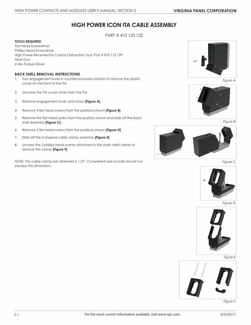
HIGH POWER iCON ITA CABLE ASSEMBLYPART # 410 123 122
TOOLS REQUIREDFlat Head ScrewdriverPhillips Head ScrewdriverHigh Power Receiver/ITA Contact Extraction Tool, Part # 910 112 129Heat GunIn-lbs Torque Driver
BACK SHELL REMOVAL INSTRUCTIONS1. Turn engagement knob in counterclockwise rotation to remove the plastic
cover on the front of the ITA
2. Unscrew the ITA cover chain from the ITA
3. Remove engagement knob and screw [Figure A].
4. Remove 4 flat head screws from the positions shown [Figure B].
5. Remove the flat head screw from the position shown and slide off the back shell assembly [Figure C].
6. Remove 2 flat head screws from the positions shown [Figure D].
7. Slide off the U-shaped cable clamp assemnly [Figure E].
8. Uncrew the 2 phillips head screws attached to the strain relief clamp to remove the clamp [Figure F].
NOTE: The cable clamp exit diameter is 1.55". Completed wire bundle should not exceed this dimension.
Figure B.
Figure C.
Figure D.
Figure F.
Figure E.
Figure A.

HIGH POWER CONTACTS AND MODULES USER’S MANUAL: SECTION 5 VIRGINIA PANEL CORPORATION
5-2 5/9/2017 For the most current information available, visit www.vpc.com.
HIGH POWER iCON ITA CABLE ASSEMBLYPART # 410 123 106, 410 123 116, AND 410 123 122
TOOLS REQUIREDFlat Head ScrewdriverPhillips Head Screwdriver3/32 Allen WrenchHigh Power Receiver/ITA Contact Extraction Tool, Part # 910 112 129Heat GunIn-lbs Torque Driver
CONTACT INSTALLATION INSTRUCTIONSNOTE: The ITA backshell must be removed prior to installing an iCon module. Please refer to the iCon User’s Manual for instructions on how to perform this step.
1. Assemble the contact to the respective wire. NOTE: Contact tested and designed for specific use with 2 AWG Cooner
Wire CW6044-14(UL Rated), AS 105-14(Non-UL), or equivalent. NOTE: For more information concerning the contact assembly process, please
see contact assembly instructions in Section 2 of this User’s Manual.
2. Ensure empty modules are secure in ITA frame.
3. Insert the assembled contacts into the back (wiring side) of module “A”, in positions 3 and 4 only for 410123106 and 410123116; once in place, pull the wire slightly to ensure that the contact is fully seated. For 410123122 all High Power positions may be used. NOTE: For more information concerning the module installation process please see module installation and removal instructions in Section 4 of this User’s Manual.
4. Insert TriPaddle contacts into the back (wiring side) of module “A”; once in place, pull the wire slightly to ensure that the contact is fully seated (All TriPaddle positions may be used).
5. Repeat steps 3 and 4 for module “B” contact loading, except that module “B” can be loaded in all four positions of the module (Figure A).
6. Route wires down both sides of engagement post (Figure B).
NOTE: Consult VPC for more information on the use of wire other than recommended.
NOTE: The cable clamp exit diameter is 1.55". Completed wire bundle should not exceed this dimension.
Figure B. Route wires around engagement post.
Figure A. Fully loaded ITA.
“B” orBOTTOMPOSITION
“A” or TOP
POSITION
HIGH POWER CONTACTS AND MODULES USER’S MANUAL: SECTION 5 VIRGINIA PANEL CORPORATION
5-3 5/9/2017 For the most current information available, visit www.vpc.com.
HIGH POWER iCON ITA CABLE ASSEMBLYPART # 410 123 106, 410 123 116, AND 410 123 122
TOOLS REQUIREDFlat Head ScrewdriverPhillips Head Screwdriver3/32 Allen WrenchHigh Power Receiver/ITA Contact Extraction Tool, Part # 910 112 129Heat GunIn-lbs Torque Driver
CONTACT INSTALLATION INSTRUCTIONSNOTE: The ITA backshell must be removed prior to installing an iCon module. Please refer to the iCon User’s Manual for instructions on how to perform this step.
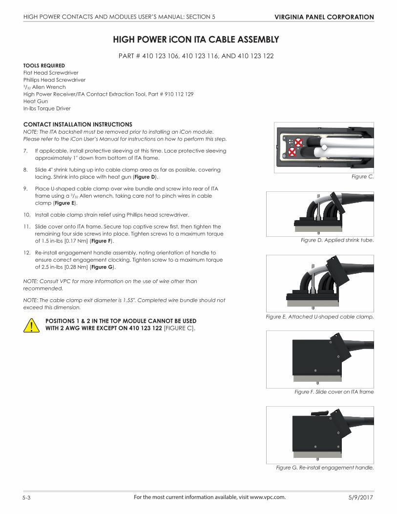
7. If applicable, install protective sleeving at this time. Lace protective sleeving approximately 1" down from bottom of ITA frame.
8. Slide 4" shrink tubing up into cable clamp area as far as possible, covering lacing. Shrink into place with heat gun (Figure D).
9. Place U-shaped cable clamp over wire bundle and screw into rear of ITA frame using a 3/32 Allen wrench, taking care not to pinch wires in cable clamp (Figure E).
10. Install cable clamp strain relief using Phillips head screwdriver.
11. Slide cover onto ITA frame. Secure top captive screw first, then tighten the remaining four side screws into place. Tighten screws to a maximum torque of 1.5 in-lbs [0.17 Nm] (Figure F).
12. Re-install engagement handle assembly, noting orientation of handle to ensure correct engagement clocking. Tighten screw to a maximum torque of 2.5 in-lbs [0.28 Nm] (Figure G).
NOTE: Consult VPC for more information on the use of wire other than recommended.
NOTE: The cable clamp exit diameter is 1.55". Completed wire bundle should not exceed this dimension.
Figure D. Applied shrink tube.
Figure E. Attached U-shaped cable clamp.
Figure F. Slide cover on ITA frame
Figure C.
POSITIONS 1 & 2 IN THE TOP MODULE CANNOT BE USED WITH 2 AWG WIRE EXCEPT ON 410 123 122 [FIGURE C].
Figure G. Re-install engagement handle.
HIGH POWER CONTACTS AND MODULES USER’S MANUAL: SECTION 5 VIRGINIA PANEL CORPORATION
5-4 5/9/2017 For the most current information available, visit www.vpc.com.
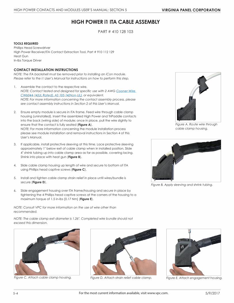
TOOLS REQUIREDPhillips Head ScrewdriverHigh Power Receiver/ITA Contact Extraction Tool, Part # 910 112 129Heat GunIn-lbs Torque Driver
CONTACT INSTALLATION INSTRUCTIONSNOTE: The ITA backshell must be removed prior to installing an iCon module. Please refer to the i1 User’s Manual for instructions on how to perform this step.
1. Assemble the contact to the respective wire. NOTE: Contact tested and designed for specific use with 2 AWG Cooner Wire
CW6044-14(UL Rated), AS 105-14(Non-UL), or equivalent. NOTE: For more information concerning the contact assembly process, please
see contact assembly instructions in Section 2 of this User’s Manual.
2. Ensure empty module is secure in ITA frame. Feed wire through cable clamp housing (uninstalled). Insert the assembled High Power and TriPaddle contacts into the back (wiring side) of module; once in place, pull the wire slightly to ensure that the contact is fully seated (Figure A).
NOTE: For more information concerning the module installation process please see module installation and removal instructions in Section 4 of this User’s Manual.
3. If applicable, install protective sleeving at this time. Lace protective sleeving approximately 1" below exit of cable clamp when in installed position. Slide 4" shrink tubing up into cable clamp area as far as possible, covering lacing. Shrink into place with heat gun (Figure B).
4. Slide cable clamp housing up length of wire and secure to bottom of ITA using Phillips head captive screws (Figure C).
5. Install and tighten cable clamp strain relief in place until wires/bundle is secure (Figure D).
6. Slide engagement housing over ITA frame/housing and secure in place by tightening the 4 Phillips head captive screws at the corners of the housing to a maximum torque of 1.5 in-lbs [0.17 Nm] (Figure E).
NOTE: Consult VPC for more information on the use of wire other than recommended.
NOTE: The cable clamp exit diameter is 1.26". Completed wire bundle should not exceed this dimension.
HIGH POWER i1 ITA CABLE ASSEMBLYPART # 410 128 103
Figure A. Route wire through cable clamp housing.
Figure B. Apply sleeving and shrink tubing.
Figure C. Attach cable clamp housing. Figure E. Attach engagement housing.Figure D. Attach strain relief cable clamp.

HIGH POWER CONTACTS AND MODULES USER’S MANUAL: SECTION 6 VIRGINIA PANEL CORPORATION
6-1 5/9/2017 For the most current information available, visit www.vpc.com.
TOOLS REQUIREDPhillips Head Screwdriver
ASSEMBLY INSTRUCTIONS 90 SERIES
1. Use a Phillips Head Screwdriver to fasten the strain relief to the 90 Series receiver module on the side of the receiver module as shown in (Figure A).
2. Wires should be restrained with slots in strain relief and be inline with the axis of its contact cavity. Twelve wire ties are included with the strain relief.
ASSEMBLY INSTRUCTIONS ICON/I1
1. Use a Phillips Head Screwdriver to fasten the strain relief to the iCon/i1 receiver module on the sides of the receiver module as shown in (Figure B).
2. Wires should be restrained with slots in strain relief and be inline with the axis of its contact cavity. Eight wire ties are included with the strain relief.
HIGH POWER ACCESSORIESPART # 510 109 549, AND 510 109 572
Figure A. 90 Series Strain Relief Installation. Figure B. iCon/i1 Strain Relief Installation.
HIGH POWER CONTACTS AND MODULES USER’S MANUAL: SECTION 7 VIRGINIA PANEL CORPORATION
7-1 5/9/2017 For the most current information available, visit www.vpc.com.
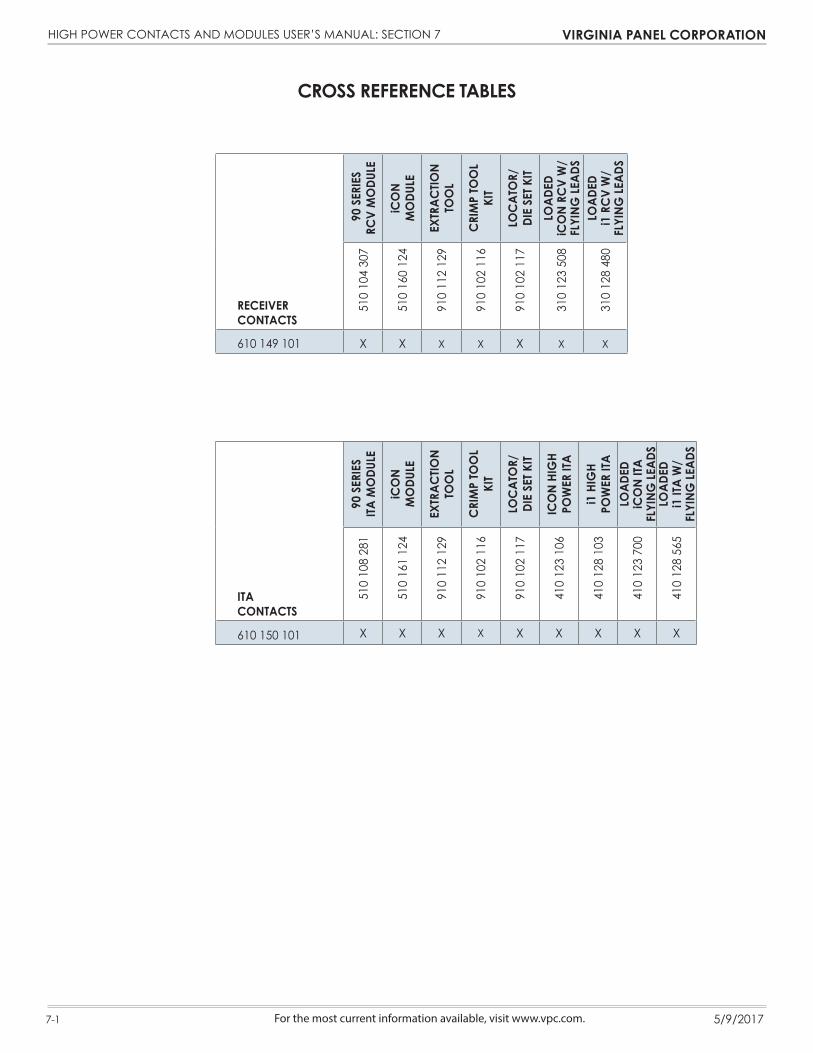
RECEIVER CONTACTS
90
SERI
ES
RCV
MO
DULE
iCO
N M
ODU
LE
EXTR
ACTIO
N TO
OL
CRI
MP
TOO
L KI
T
LOC
ATO
R/DI
E SE
T KIT
LOAD
ED
iCO
N RC
V W
/ FL
YING
LEAD
SLO
ADED
i1
RC
V W
/ FL
YING
LEAD
S
510
104
307
510
160
124
910
112
129
910
102
116
910
102
117
310
123
508
310
128
480
610 149 101 X X X X X X X
ITA CONTACTS
90 S
ERIE
S ITA
MO
DULE
iCO
N M
ODU
LE
EXTR
ACTIO
N TO
OL
CRI
MP
TOO
L KI
T
LOC
ATO
R/DI
E SE
T KIT
ICO
N HI
GH
POW
ER IT
A
i1 H
IGH
POW
ER IT
ALO
ADED
iC
ON
ITA
FLYI
NG LE
ADS
LOAD
ED
i1 IT
A W
/ FL
YING
LEAD
S
510
108
281
510
161
124
910
112
129
910
102
116
910
102
117
410
123
106
410
128
103
410
123
700
410
128
565
610 150 101 X X X X X X X X X
CROSS REFERENCE TABLES

HIGH POWER CONTACTS AND MODULES USER’S MANUAL: APPENDIX VIRGINIA PANEL CORPORATION
For the most current information available, visit www.vpc.com. 5/9/2017
HIGH POWER CONTACT ELECTRICAL SPECIFICATIONS
Electrical Specifications
Operating Current 150 Amp Continuous using 2 AWG wire
Operating Voltage 600VDC or Peak AC
Contact Resistance 0.35 mOhms
Dielectric Withstanding Voltage 1500VDC Minimum
Insulation Resistance 1000 Mohms Minimum
Temperature Rise +40°C at 150 Amps+30°C at 125 Amps
Mechanical Characteristics
Mating Force 2.5 lb Max [1.13 Kg]
Cycle Life 10,000 cycles
Material
Contact Body Material Cu Alloy
Receiver Contact Body Plating 10μ" Au over 100μ" Ni
ITA Contact Body Plating 30μ" Au over 100μ" Ni
Operating Temperature -40°C to 125°C
8.83.348
11.12.438
12.70.500
38.481.515
5.89.232
36.201.425
12.70.500
5.72.225
8.83.348
11.12.438
Receiver ContactPart # 610 149 101
ITA ContactPart # 610 150 101
Dimensions shown: [millimeters] inches
1 of 6

HIGH POWER CONTACTS AND MODULES USER’S MANUAL: APPENDIX VIRGINIA PANEL CORPORATION
For the most current information available, visit www.vpc.com. 5/9/2017
High Power ConnectorProduct Performance Specification
1. Scope
1.1 Content
This specification covers the performance, tests and quality requirements for the High Power contact and connector system. The High Power contact is a separable electrical connection device, designed and tested using 2 AWG Cooner Wire CW6044-14(UL Rated), AS 105-14(Non-UL) wire. All High Power contact types are to be used in High Power connector modules. 1.2 Qualification Testing When tests are performed on subject product line, the following procedures shall be used: • All inspections shall be performed using applicable inspection plans and product drawings. • Upon completion of qualification testing, this specification will be assigned a number and be classified, 2. Applicable Documents 2.1 Content The following documents form a part of this specification to the extent specified herein. Unless otherwise specified, the latest edition of the document applies. In the event of a conflict between requirements of this specification and product drawing, the product drawing will take precedence. In the event of a conflict between requirements of this specification and referenced documents, this specification shall take precedence. 2.2 Documents A. Standards: • AMS 2422 • EIA 364-06 • EIA 364-5 • EIA 364-29 • EIA 364-21 • EIA 364-09 • EIA 364-13 • EIA 364-17 • EIA 364-20 B. Product Drawings: Housings • 510104307 • 510108281 • 510160124 • 510161124 Contacts • 610149101 • 610150101
2 of 6
HIGH POWER CONTACTS AND MODULES USER’S MANUAL: APPENDIX VIRGINIA PANEL CORPORATION
For the most current information available, visit www.vpc.com. 5/9/2017
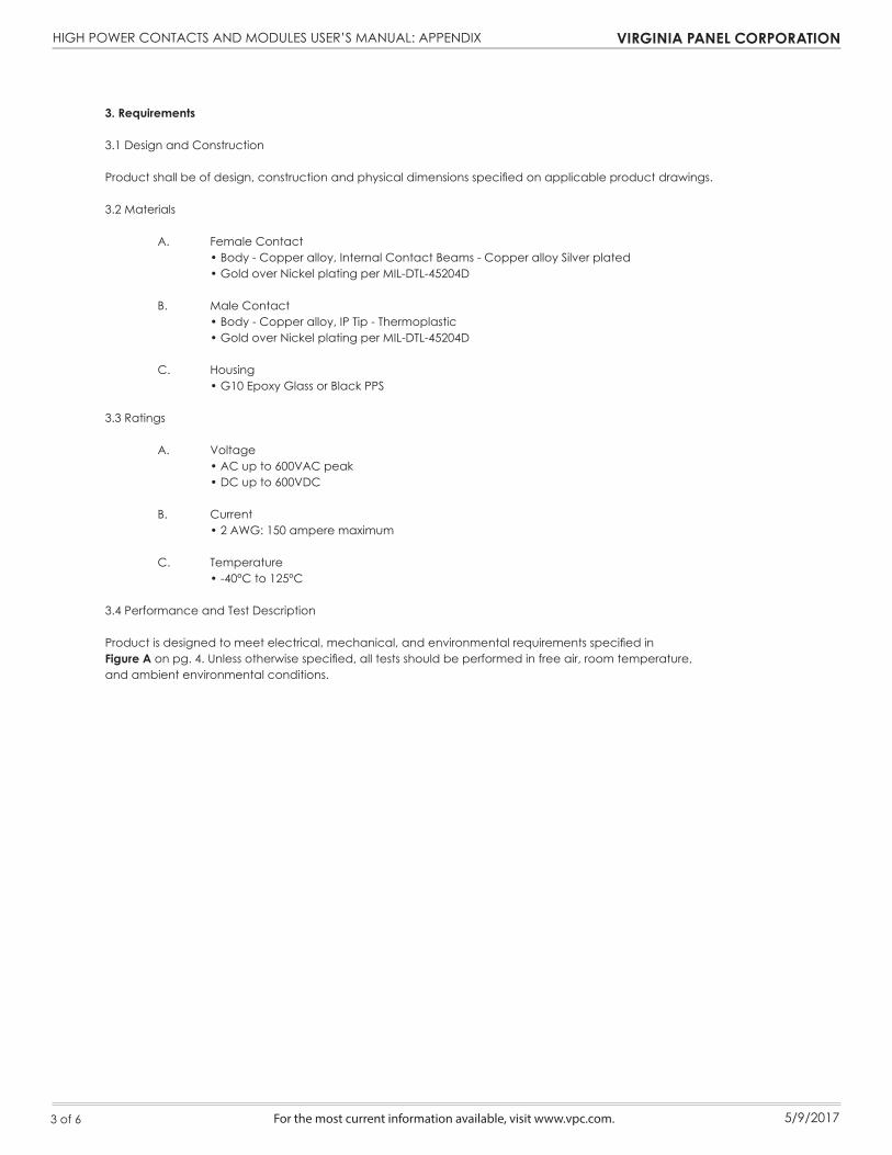
3. Requirements
3.1 Design and Construction
Product shall be of design, construction and physical dimensions specified on applicable product drawings.
3.2 Materials A. Female Contact • Body - Copper alloy, Internal Contact Beams - Copper alloy Silver plated • Gold over Nickel plating per MIL-DTL-45204D B. Male Contact • Body - Copper alloy, IP Tip - Thermoplastic • Gold over Nickel plating per MIL-DTL-45204D
C. Housing • G10 Epoxy Glass or Black PPS 3.3 Ratings
A. Voltage • AC up to 600VAC peak • DC up to 600VDC
B. Current • 2 AWG: 150 ampere maximum C. Temperature • -40°C to 125°C 3.4 Performance and Test Description
Product is designed to meet electrical, mechanical, and environmental requirements specified in Figure A on pg. 4. Unless otherwise specified, all tests should be performed in free air, room temperature, and ambient environmental conditions.
3 of 6
HIGH POWER CONTACTS AND MODULES USER’S MANUAL: APPENDIX VIRGINIA PANEL CORPORATION
For the most current information available, visit www.vpc.com. 5/9/2017
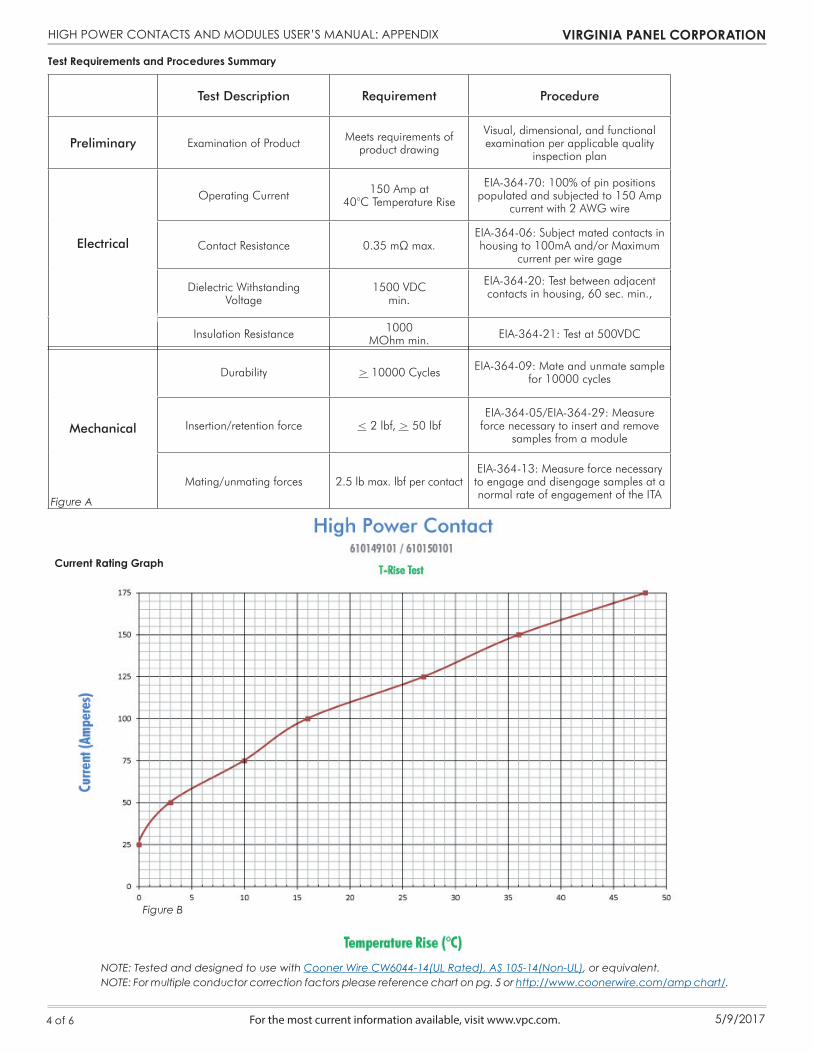
Test Requirements and Procedures Summary
NOTE: Tested and designed to use with Cooner Wire CW6044-14(UL Rated), AS 105-14(Non-UL), or equivalent.NOTE: For multiple conductor correction factors please reference chart on pg. 5 or http://www.coonerwire.com/amp chart/.
Test Description Requirement Procedure
Preliminary Examination of Product Meets requirements ofproduct drawing
Visual, dimensional, and functionalexamination per applicable quality
inspection plan
Electrical
Operating Current 150 Amp at40°C Temperature Rise
EIA-364-70: 100% of pin positions populated and subjected to 150 Amp
current with 2 AWG wire
Contact Resistance 0.35 mΩ max.EIA-364-06: Subject mated contacts in housing to 100mA and/or Maximum
current per wire gage
Dielectric Withstanding Voltage
1500 VDCmin.
EIA-364-20: Test between adjacent contacts in housing, 60 sec. min.,
Insulation Resistance 1000 MOhm min. EIA-364-21: Test at 500VDC
4 of 6
Current Rating Graph
Figure A
Figure B
Mechanical
Durability > 10000 Cycles EIA-364-09: Mate and unmate sample for 10000 cycles
Insertion/retention force < 2 lbf, > 50 lbfEIA-364-05/EIA-364-29: Measure
force necessary to insert and remove samples from a module
Mating/unmating forces 2.5 lb max. lbf per contactEIA-364-13: Measure force necessary to engage and disengage samples at a normal rate of engagement of the ITA
HIGH POWER CONTACTS AND MODULES USER’S MANUAL: APPENDIX VIRGINIA PANEL CORPORATION
For the most current information available, visit www.vpc.com. 5/9/2017
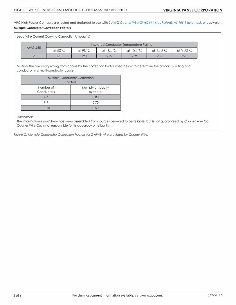
Lead Wire Current Carrying Capacity (Ampacity)
Multiply the ampacity rating from above by the correction factor listed below to determine the ampacity rating of aconductor in a multi-conductor cable.
Disclaimer:The information shown here has been assembled from sources believed to be reliable, but is not guaranteed by Cooner Wire Co. Cooner Wire Co. is not responsible for its accuracy or reliability.
Multiple Conductor Correction Factors
AWG SIZEInsulated Conductor Temperature Rating
at 80°C at 90°C at 105°C at 125°C at 150°C at 200°C2 170 190 215 232 255 293
Multiple Conductor CorrectionFactors
Number of Conductors
Multiply ampacityby factor
4-6 0.80
7-9 0.70
10-20 0.50
VPC High Power Contacts are tested and designed to use with 2 AWG Cooner Wire CW6044-14(UL Rated), AS 105-14(Non-UL), or equivalent.
Figure C. Multiple Conductor Correction Factors for 2 AWG wire provided by Cooner Wire.
5 of 6

HIGH POWER CONTACTS AND MODULES USER’S MANUAL: APPENDIX VIRGINIA PANEL CORPORATION
For the most current information available, visit www.vpc.com. 5/9/2017
4. Quality Assurance Provisions
4.1 Qualification Testing
A. Sample Selection Samples shall be prepared in accordance with applicable instruction sheets and shall be selected at random from current production. Each test group shall consist of a minimum of 5 connectors containing at least 30 contacts total each and equal posts to mate with receptacles. B. Test Sequence Qualification inspection shall be verified by testing samples as specified in Figure A on pg. 4. 4.2 Requalification Testing If changes which significantly affect form, fit or function are made to product or manufacturing process, quality assurance shall coordinate requalification testing, consisting of all or part of original testing sequence as determined by development, product, and quality, and reliability engineering. 4.3 Acceptance Acceptance is based on verification that product meets requirements of Figure A on pg. 4. Failures attributed to equipment, test set-up or operator deficiencies shall not disqualify product. When product failure occurs, corrective action shall be taken and samples resubmitted for qualification. Testing to confirm corrective action is required before re-submittal. 4.4 Quality Conformance Inspection A Certificate of Conformance dimensional inspection must be completed for all samples prior to qualification testing. The applicable quality inspection plan will specify sampling acceptable quality level to be used. Dimensional and functional requirements shall be in accordance with applicable product drawing and this specification.
REV Date Rev Change Prepared By
1 11/27/13 Original Release R. Brightwell
2 1/20/2014 Market Release R. Brightwell
3 1/22/2014 Official Market Release C. Slagle
4 3/10/2014 Updated R. Brightwell
5 5/28/2014 Update J. Harman
6 11/25/2014 Update J. Harman
7 5/9/2017 Update J. Diggs
6 of 6