Embed Size (px)
Citation preview
Assembly instructionsSlat band chain conveyor systems CS SL

Assembly instructionsSlat band chain conveyor systems CS SL
305.2011 J170 055 / EN
Contents
1 General 5. . . . . . . . . . . . . . . . . . . . . . . . . . . . . . . . . . . . .
1.1 Reservation 5. . . . . . . . . . . . . . . . . . . . . . . . . . . . .
1.2 Explanation of safety symbols 5. . . . . . . . . . . . .
2 Proper use 6. . . . . . . . . . . . . . . . . . . . . . . . . . . . . . . . . .
2.1 Declaration of Incorporation 7. . . . . . . . . . . . . . .
3 General operating conditions 8. . . . . . . . . . . . . .
4 General technical conditions 9. . . . . . . . . . . . .
4.1 Chain pulling force 10. . . . . . . . . . . . . . . . . . . . . . .
4.2 Noise emission 11. . . . . . . . . . . . . . . . . . . . . . . . . .
5 Technical specifications 12. . . . . . . . . . . . . . . . . .
5.1 CS 065 SL 12. . . . . . . . . . . . . . . . . . . . . . . . . . . . . .
5.1.1 Conveyor chains 12. . . . . . . . . . . . . . . . . . . . . . . . .
5.1.2 Drives 13. . . . . . . . . . . . . . . . . . . . . . . . . . . . . . . . . .
5.1.3 Idlers 13. . . . . . . . . . . . . . . . . . . . . . . . . . . . . . . . . . .
5.2 CS 090 SL 14. . . . . . . . . . . . . . . . . . . . . . . . . . . . . .
5.2.1 Conveyor chains 14. . . . . . . . . . . . . . . . . . . . . . . . .
5.2.2 Drives 15. . . . . . . . . . . . . . . . . . . . . . . . . . . . . . . . . .
5.2.3 Idlers 15. . . . . . . . . . . . . . . . . . . . . . . . . . . . . . . . . . .
5.3 CS 200 SL 16. . . . . . . . . . . . . . . . . . . . . . . . . . . . . .
5.3.1 Conveyor chains 16. . . . . . . . . . . . . . . . . . . . . . . . .
5.3.2 Drives 16. . . . . . . . . . . . . . . . . . . . . . . . . . . . . . . . . .
5.3.3 Idlers 17. . . . . . . . . . . . . . . . . . . . . . . . . . . . . . . . . . .
6 Safety warnings 18. . . . . . . . . . . . . . . . . . . . . . . . . . . .
6.1 Owner’s obligation to exercise due care 18. . . . .
6.2 Operator’s obligation to exercise due care 18. . .
6.3 Potential residual risks 19. . . . . . . . . . . . . . . . . . . .
6.3.1 Measures to avoids residual risks 19. . . . . . . . . .
7 Transportation and storage 20. . . . . . . . . . . . . . .
8 Assembly 21. . . . . . . . . . . . . . . . . . . . . . . . . . . . . . . . . . .
8.1 Installing guide profiles 21. . . . . . . . . . . . . . . . . . . .
8.1.1 Installing line section joints 21. . . . . . . . . . . . . . . .
8.2 Installing function units 22. . . . . . . . . . . . . . . . . . . .
8.2.1 Vertical idler 22. . . . . . . . . . . . . . . . . . . . . . . . . . . . .
8.2.2 Drives 22. . . . . . . . . . . . . . . . . . . . . . . . . . . . . . . . . .
8.2.2.1 Setting slip-clutch torque 23. . . . . . . . . . . . . . . . . .
8.2.2.2 Reducing slip-clutch torque 24. . . . . . . . . . . . . . . .
8.2.2.3 Setting pretensioning force of tensioning box 25.
8.2.2.4 Setting tension of flat belt 25. . . . . . . . . . . . . . . . . .
8.3 Installing sliding strips 26. . . . . . . . . . . . . . . . . . . .
8.3.1 Screwing down sliding strip 27. . . . . . . . . . . . . . . .
8.3.1.1 Screwing down at joints 29. . . . . . . . . . . . . . . . . . .
8.3.1.2 Screwing down upstream of function units 29. . .
8.3.2 Sliding-strip projection at the horizontal curvewith disc 30. . . . . . . . . . . . . . . . . . . . . . . . . . . . . . . .
8.4 Checking assembled line 30. . . . . . . . . . . . . . . . . .
8.5 Drawing conveyor chain into the line 31. . . . . . . .
8.6 Line crossovers 33. . . . . . . . . . . . . . . . . . . . . . . . . .
8.6.1 Roll transfer 33. . . . . . . . . . . . . . . . . . . . . . . . . . . . .
8.6.2 Crossover with railing 34. . . . . . . . . . . . . . . . . . . . .
8.6.2.1 Parallel crossover 34. . . . . . . . . . . . . . . . . . . . . . . .
8.6.2.2 Curved crossover 34. . . . . . . . . . . . . . . . . . . . . . . .
9 Start-up 35. . . . . . . . . . . . . . . . . . . . . . . . . . . . . . . . . . . . .
9.1 Danger zones 35. . . . . . . . . . . . . . . . . . . . . . . . . . .
9.2 Normal operation 36. . . . . . . . . . . . . . . . . . . . . . . .
9.3 Hot motors 36. . . . . . . . . . . . . . . . . . . . . . . . . . . . . .
10 Maintenance, cleaning and servicing 37. . . .
10.1 Conveyor chain lubrication 38. . . . . . . . . . . . . . . .
10.2 Drive units with chain gear 38. . . . . . . . . . . . . . . .
10.3 Drive units with belt reducing gear 39. . . . . . . . . .
10.4 Shortening or renewing conveyor chain 40. . . . .
11 Troubleshooting 42. . . . . . . . . . . . . . . . . . . . . . . . . . .
12 Taking out of operation 43. . . . . . . . . . . . . . . . . . . .
13 Disposal 43. . . . . . . . . . . . . . . . . . . . . . . . . . . . . . . . . . . .
Reproduction, even in part, is not permitted except with our approval. We reserve the right to make changes in the interests of technicalprogress. Our general sales and delivery conditions apply.E 2011 MS Plus Automation
Assembly instructionsSlat band chain conveyor systems CS SL
4 05.2011J170 055 / EN
Contents
14 Appendix: Drawings and parts lists 44. . . . . .
15 CS 065 SL 45. . . . . . . . . . . . . . . . . . . . . . . . . . . . . .
15.1 CS 065 SL vertical drive, with belt reducinggear 45. . . . . . . . . . . . . . . . . . . . . . . . . . . . . . . . . . . .
15.1.1 Parts list for CS 065 SL vertical drive, withbelt reducing gear 46. . . . . . . . . . . . . . . . . . . . . . . .
15.2 CS 065 SL vertical drive, with chain gear 47. . . .
15.2.1 Parts list for CS 065 SL vertical drive, withchain gear 48. . . . . . . . . . . . . . . . . . . . . . . . . . . . . .
15.3 CS 065 SL direct drive 49. . . . . . . . . . . . . . . . . . . .
15.3.1 Parts list for CS 065 SL direct drive 50. . . . . . . . .
15.4 CS 065 SL centre drive, with belt reducinggear 51. . . . . . . . . . . . . . . . . . . . . . . . . . . . . . . . . . . .
15.4.1 Parts list for CS 065 SL centre drive, with beltreducing gear 52. . . . . . . . . . . . . . . . . . . . . . . . . . .
15.5 CS 065 SL centre drive, with chain gear 53. . . . .
15.5.1 Parts list for CS 065 SL centre drive, withchain gear 54. . . . . . . . . . . . . . . . . . . . . . . . . . . . . .
15.6 CS 065 SL direct centre drive 55. . . . . . . . . . . . . .
15.6.1 Parts list for CS 065 SL direct centre drive 56. . .
15.7 CS 065 SL vertical idler, 180˚ 57. . . . . . . . . . . . . .
15.7.1 Parts list for CS 065 SL vertical idler, 180˚ 57. . .
15.8 CS 065 SL horizontal curve with disk 58. . . . . . .
15.8.1 Parts list for CS 065 SL horizontal curvewith disk 59. . . . . . . . . . . . . . . . . . . . . . . . . . . . . . . .
16 CS 090 SL 60. . . . . . . . . . . . . . . . . . . . . . . . . . . . . .
16.1 CS 090 SL vertical drive, with belt reducinggear 60. . . . . . . . . . . . . . . . . . . . . . . . . . . . . . . . . . . .
16.1.1 Parts list for CS 090 SL vertical drive, withchain gear 61. . . . . . . . . . . . . . . . . . . . . . . . . . . . . .
16.2 CS 090 SL vertical drive, with chain gear 62. . . .
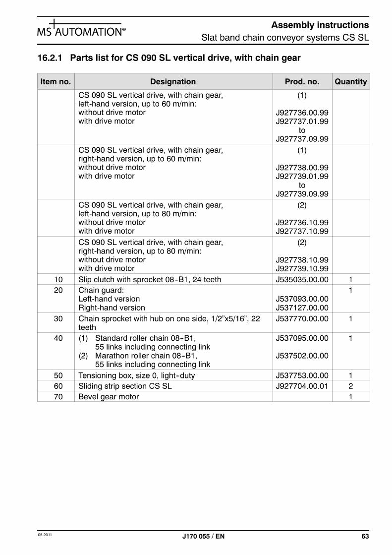
16.2.1 Parts list for CS 090 SL vertical drive, withchain gear 63. . . . . . . . . . . . . . . . . . . . . . . . . . . . . .
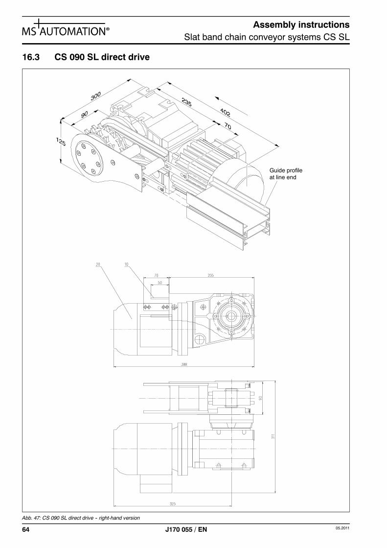
16.3 CS 090 SL direct drive 64. . . . . . . . . . . . . . . . . . . .
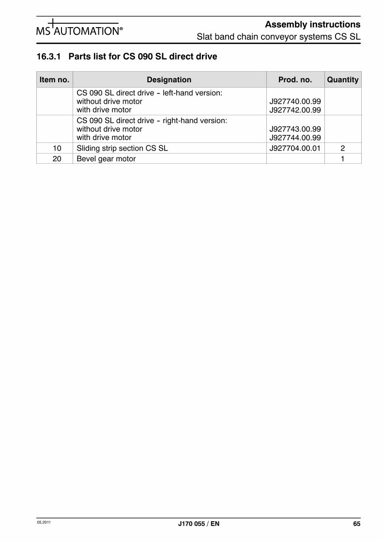
16.3.1 Parts list for CS 090 SL direct drive 65. . . . . . . . .
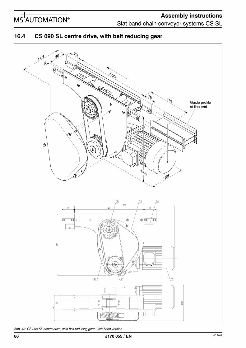
16.4 CS 090 SL centre drive, with belt reducinggear 66. . . . . . . . . . . . . . . . . . . . . . . . . . . . . . . . . . . .
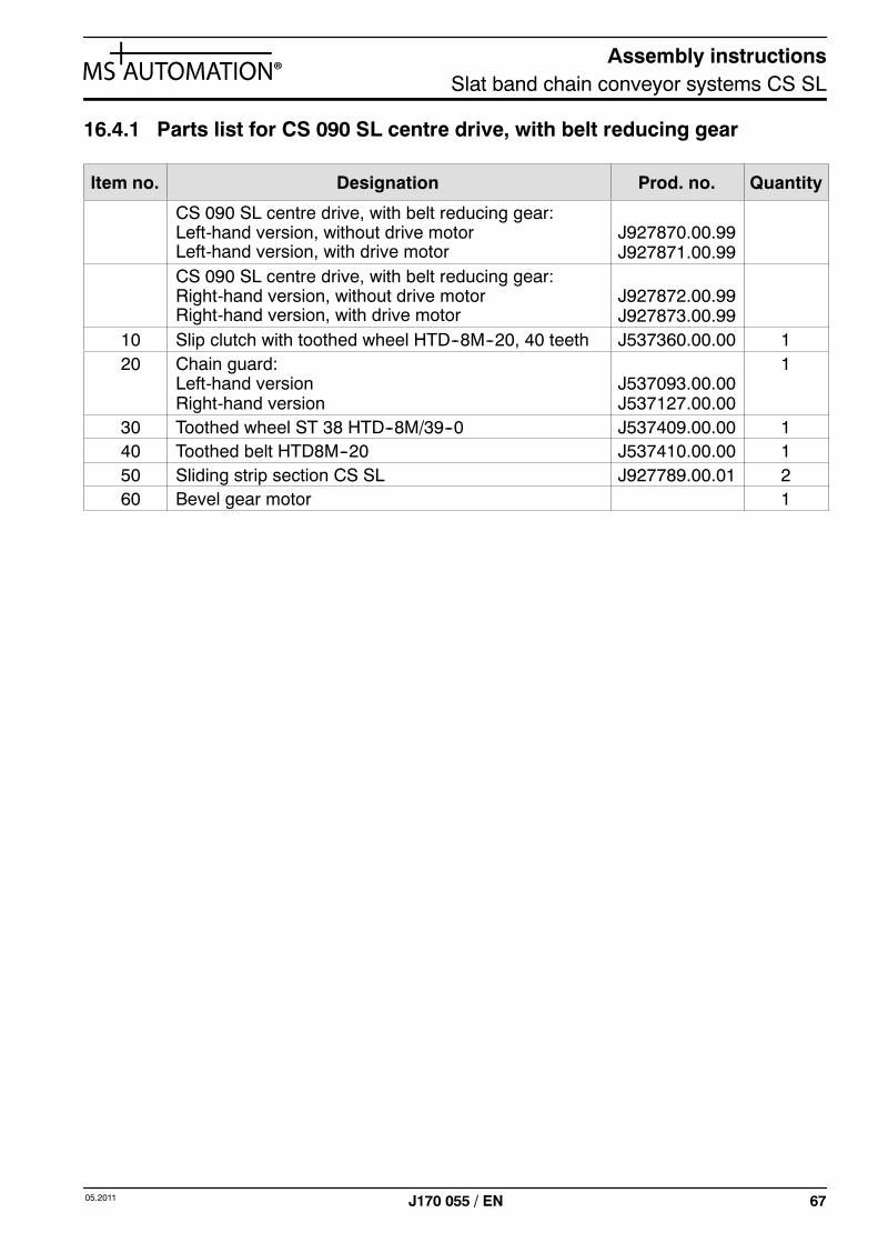
16.4.1 Parts list for CS 090 SL centre drive, with beltreducing gear 67. . . . . . . . . . . . . . . . . . . . . . . . . . .
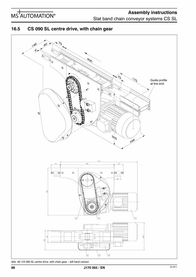
16.5 CS 090 SL centre drive, with chain gear 68. . . . .
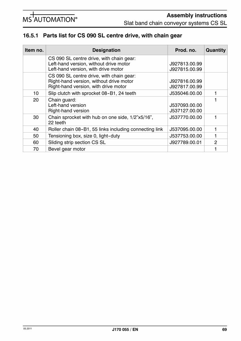
16.5.1 Parts list for CS 090 SL centre drive, withchain gear 69. . . . . . . . . . . . . . . . . . . . . . . . . . . . . .
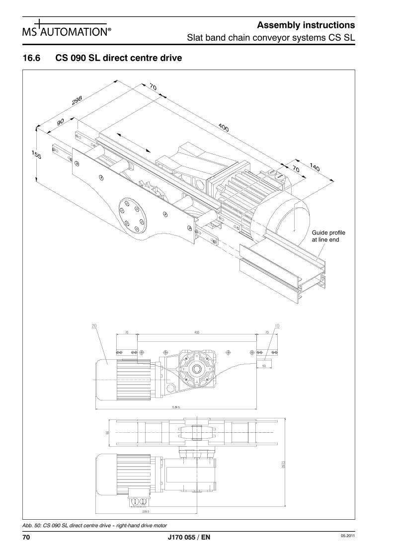
16.6 CS 090 SL direct centre drive 70. . . . . . . . . . . . . .
16.6.1 Parts list for CS 090 SL direct centre drive 71. . .
16.7 CS 090 SL vertical idler, 180˚ 72. . . . . . . . . . . . . .
16.7.1 Parts list for CS 090 SL vertical idler, 180˚ 72. . .
16.8 CS 090 SL horizontal curve with disk 73. . . . . . .
16.8.1 Parts list for CS 090 SL horizontal curvewith disk 74. . . . . . . . . . . . . . . . . . . . . . . . . . . . . . . .
17 CS 200 SL 75. . . . . . . . . . . . . . . . . . . . . . . . . . . . . .
17.1 CS 200 SL vertical drive, with belt reducinggear 75. . . . . . . . . . . . . . . . . . . . . . . . . . . . . . . . . . . .
17.1.1 Parts list for CS 200 SL vertical drive, with beltreducing gear 76. . . . . . . . . . . . . . . . . . . . . . . . . . .
17.2 CS 200 SL vertical drive, with chain gear 77. . . .
17.2.1 Parts list for CS 200 SL vertical drive, withchain gear 78. . . . . . . . . . . . . . . . . . . . . . . . . . . . . .
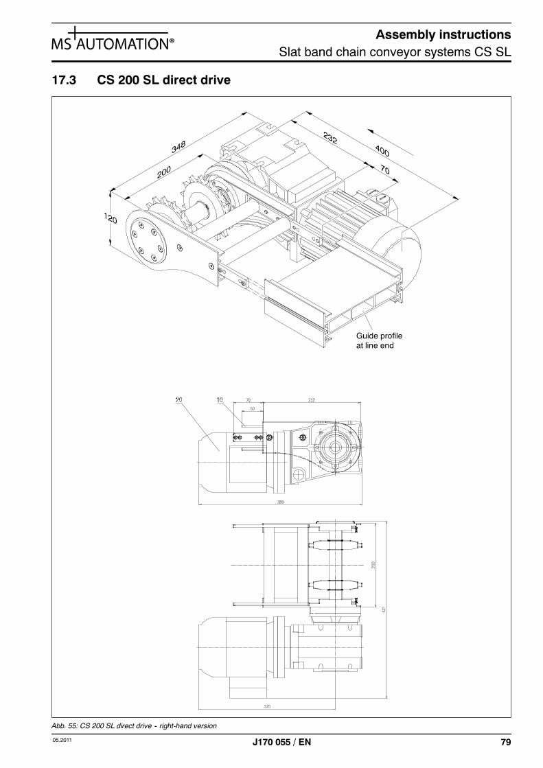
17.3 CS 200 SL direct drive 79. . . . . . . . . . . . . . . . . . . .
17.3.1 Parts list for CS 200 SL direct drive 80. . . . . . . . .
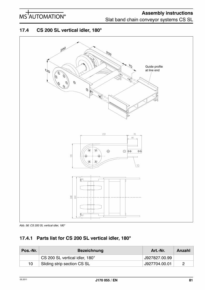
17.4 CS 200 SL vertical idler, 180˚ 81. . . . . . . . . . . . . .
17.4.1 Parts list for CS 200 SL vertical idler, 180˚ 81. . .
Assembly instructionsSlat band chain conveyor systems CS SL
505.2011 J170 055 / EN
1 General
These assembly instructions for partly completed machines comply withDIN EN ISO 12100--2/A1. The manufacturer has included them with the product toprovide the owner and operator of the machine with the fundamental knowledgerequired for its safe and proper operation.
The assembly instructions should always be kept within easy reach in machineproximity.
The assembly instructions provide assistance in using, servicing and maintainingthe machine. They are intended to contribute towards extending the system’s use-ful life under high-capacity use and help prevent accidents.
Caution! Read the assembly instructions through carefully before putting the machine into /back into operation. The manufacturer accepts no liability for damage and mal-functions resulting from any failure to observe these operating instructions!
1.1 Reservation
We reserve the right to make technical modifications diverging from the illustrations and infor-mation provided in these assembly instructions if such help to improve the machine.
The assembly instructions may only be duplicated for internal use. They must not be passedon to third parties.
1.2 Explanation of safety symbols
The safety symbols together with the wording of the safety warning are intended to draw at-tention to unavoidable residual risks involved in handling and using the machine.
These residual risks relate to persons, the machine, other property and objects as well as tothe environment.
The following safety symbols are used in these assembly instructions. In particular, these sym-bols are intended to draw the reader’s attention to the wording of the safety warning appearingnext to them.
Caution! Warning of a point of danger.
This symbol points draws attention to dangers posing a particular threat to life and health -- inaddition to this, risks may also exist for machine, property or the environment.
Assembly instructionsSlat band chain conveyor systems CS SL
6 05.2011J170 055 / EN
Caution! Warning of dangerous voltage.
This symbol draws attention to particular threats to life and health from dangerous voltages.
Any work necessary must only be performed by persons in possession of the requisite exper-tise (e.g. qualified electricians or persons with electrotechnical training) and who have beeninstructed to do so by the company owning the system.
Caution! Important note that must be observed.
This note without additional safety symbol marks passages in these assembly instructionswhere it is necessary to observe guidelines, regulations, information and the correct sequenceof work as well as avoid causing damage to the machine.
2 Proper use
The vertical and centre drives as well as the vertical idlers and horizontal curves with disk oftype CS SL in CS 065 SL, CS 090 SL and CS 200 SL overall widths -- also referred to belowas drives and idlers -- are only intended for use as components in constructing an overallsystem.
This overall system is slat band chain conveyor for moving unit loads and in which a curve-going link chain is guided in a guide profile.
The drives have the purpose of transferring motor power to the conveyor chain. They are usedat the end/centre of the line. The vertical idlers are used for returning the chain to the start ofthe line.
Caution! The conveyor system must only be set up indoors where it is protected from theelements. The system must not be operated in potentially explosive atmospheres.
Caution! Proper use also includes reading these assembly instructions as well as followingall of the information contained in them -- in particular the safety warnings. Thisalso includes carrying out all servicing and maintenance work at the prescribedintervals.
If the conveyor system is not used for its intended purpose, safe operation will not be ensured.
It is the owner and operator of the conveyor system, and not the manufacturer, who is respon-sible for all personal injury and damage to property resulting from improper use!
Assembly instructionsSlat band chain conveyor systems CS SL
705.2011 J170 055 / EN
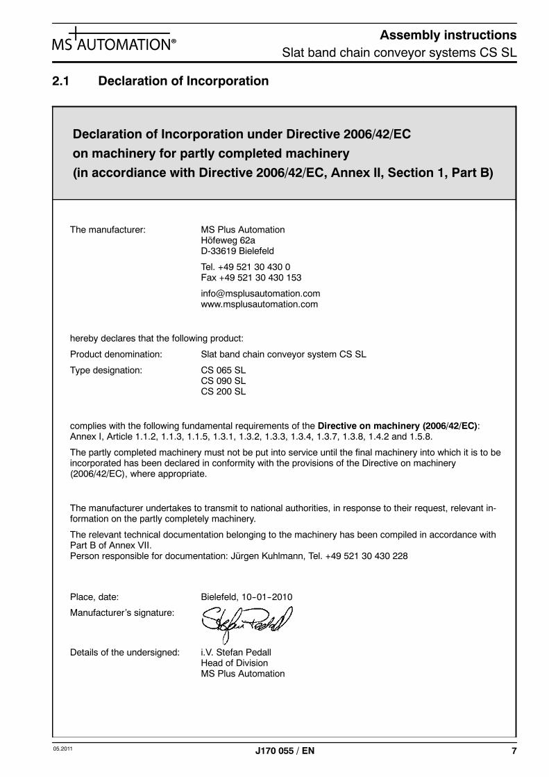
2.1 Declaration of Incorporation
Place, date: Bielefeld, 10--01--2010
Manufacturer’s signature:
Details of the undersigned: i.V. Stefan PedallHead of DivisionMS Plus Automation
The manufacturer: MS Plus AutomationHöfeweg 62aD-33619 Bielefeld
Tel. +49 521 30 430 0Fax +49 521 30 430 153
hereby declares that the following product:
Product denomination: Slat band chain conveyor system CS SL
Type designation: CS 065 SLCS 090 SLCS 200 SL
complies with the following fundamental requirements of the Directive on machinery (2006/42/EC):Annex I, Article 1.1.2, 1.1.3, 1.1.5, 1.3.1, 1.3.2, 1.3.3, 1.3.4, 1.3.7, 1.3.8, 1.4.2 and 1.5.8.
The partly completed machinery must not be put into service until the final machinery into which it is to beincorporated has been declared in conformity with the provisions of the Directive on machinery(2006/42/EC), where appropriate.
The manufacturer undertakes to transmit to national authorities, in response to their request, relevant in-formation on the partly completely machinery.
The relevant technical documentation belonging to the machinery has been compiled in accordance withPart B of Annex VII.Person responsible for documentation: Jürgen Kuhlmann, Tel. +49 521 30 430 228
Declaration of Incorporation under Directive 2006/42/EC
on machinery for partly completed machinery
(in accordiance with Directive 2006/42/EC, Annex II, Section 1, Part B)
Assembly instructionsSlat band chain conveyor systems CS SL
8 05.2011J170 055 / EN
3 General operating conditions
Description
The conveyor system is a slat band chain conveyor for handling unit loads.
The aluminium guide profile accommodates a curve-going link chain made of plastic. Clip-onsliding strips minimise sliding friction between chain and profile.
Plastic chains
The plastic chains required for operation are made of POM.
The individual links are fitted together without connecting bolts. The chains exhibit good resi-stance to chemicals as well as to liquids with a pH value of 4.5 to 9 (list on request).
Ambient conditions
Permissible operating temperature range from --20 to +80°C.
Conveyor chain lubrication
CS SL conveyor systems can in general be operated without lubrication. This is made possibleby the excellent material properties of the sliding strip.
Assembly instructionsSlat band chain conveyor systems CS SL
905.2011 J170 055 / EN
4 General technical conditions
Width of conveyed item
The maximum width of items being conveyed is governed by their shape and the position oftheir gravitational centre.
Weight of conveyed item
Horizontal conveyance:The maximum weight of individual conveyed items is limited by sliding-strip wear and chainpulling force.
Vertical conveyance:The maximum weight of individual conveyed items is governed by the strength of the catchplates.
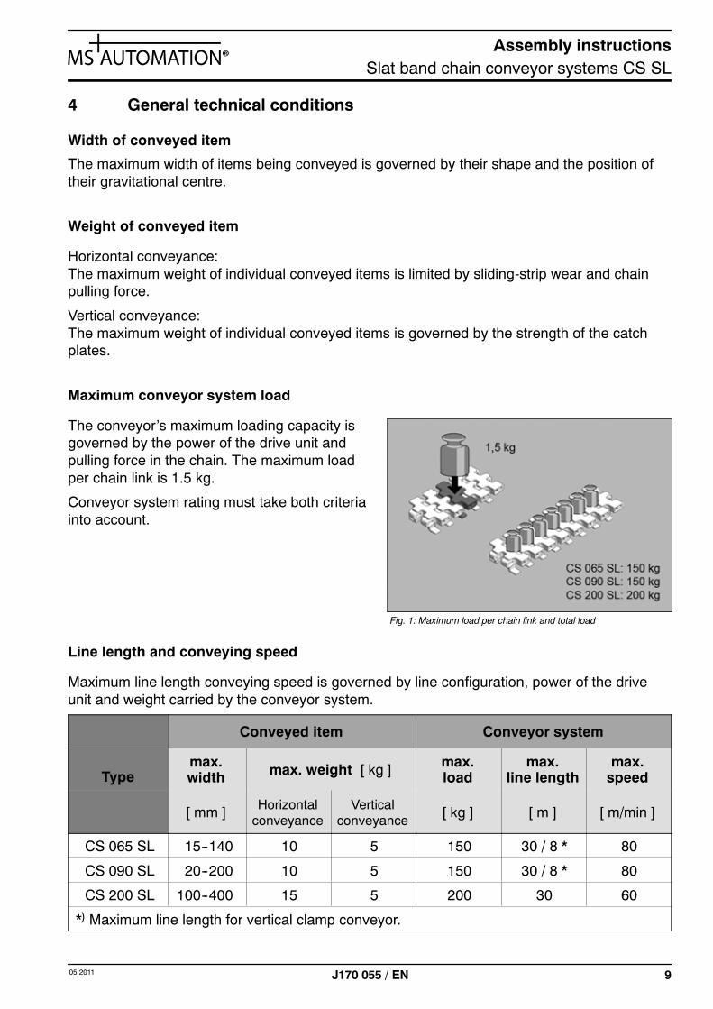
Maximum conveyor system load
The conveyor’s maximum loading capacity isgoverned by the power of the drive unit andpulling force in the chain. The maximum loadper chain link is 1.5 kg.
Conveyor system rating must take both criteriainto account.
Line length and conveying speed
Maximum line length conveying speed is governed by line configuration, power of the driveunit and weight carried by the conveyor system.
Conveyed item Conveyor system
Typemax.width max. weight [ kg ] max.
loadmax.
line lengthmax.
speed
[ mm ] Horizontalconveyance
Verticalconveyance
[ kg ] [ m ] [ m/min ]
CS 065 SL 15--140 10 5 150 30 / 8 * 80
CS 090 SL 20--200 10 5 150 30 / 8 * 80
CS 200 SL 100--400 15 5 200 30 60
*) Maximum line length for vertical clamp conveyor.
Fig. 1: Maximum load per chain link and total load
Assembly instructionsSlat band chain conveyor systems CS SL
10 05.2011J170 055 / EN
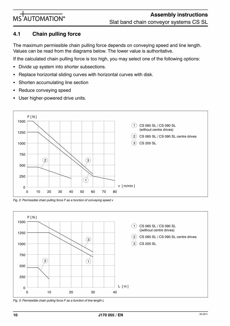
4.1 Chain pulling force
The maximum permissible chain pulling force depends on conveying speed and line length.Values can be read from the diagrams below. The lower value is authoritative.
If the calculated chain pulling force is too high, you may select one of the following options:
S Divide up system into shorter subsections.
S Replace horizontal sliding curves with horizontal curves with disk.
S Shorten accumulating line section
S Reduce conveying speed
S User higher-powered drive units.
F [ N ]
1250
1000
750
500
250
0 20 40 60 80
v [ m/min ]010 30 50 70
1500
3
1
2
1 CS 065 SL / CS 090 SL(without centre drives)
2 CS 065 SL / CS 090 SL centre drives
3 CS 200 SL
Fig. 2: Permissible chain pulling force F as a function of conveying speed v
1 CS 065 SL / CS 090 SL((without centre drives)
2 CS 065 SL / CS 090 SL centre drives
3 CS 200 SL
F [ N ]
1250
1000
750
500
250
0 10 20 30 40
L [ m ]0
1500
3
12
Fig. 3: Permissible chain pulling force F as a function of line length L
Assembly instructionsSlat band chain conveyor systems CS SL
1105.2011 J170 055 / EN
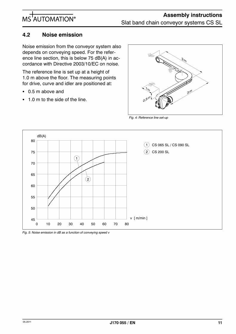
4.2 Noise emission
Noise emission from the conveyor system alsodepends on conveying speed. For the refer-ence line section, this is below 75 dB(A) in ac-cordance with Directive 2003/10/EC on noise.
The reference line is set up at a height of1.0 m above the floor. The measuring pointsfor drive, curve and idler are positioned at:
S 0.5 m above and
S 1.0 m to the side of the line.
1 CS 065 SL / CS 090 SL
2 CS 200 SL
1
2
dB(A)80
75
70
65
60
0 20 40 60 80
v [ m/min ]
55
10 30 50 70
50
45
Fig. 5: Noise emission in dB as a function of conveying speed v
Fig. 4: Reference line set-up
Assembly instructionsSlat band chain conveyor systems CS SL
12 05.2011J170 055 / EN
5 Technical specifications
5.1 CS 065 SL
S Overall width 65 mm
S Guide profile material EN AW--6063 T66, E6/EV1 anodised finish
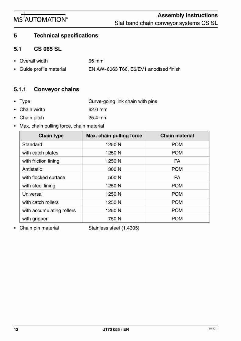
5.1.1 Conveyor chains
S Type Curve-going link chain with pins
S Chain width 62.0 mm
S Chain pitch 25.4 mm
S Max. chain pulling force, chain material
Chain type Max. chain pulling force Chain material
Standard 1250 N POM
with catch plates 1250 N POM
with friction lining 1250 N PA
Antistatic 300 N POM
with flocked surface 500 N PA
with steel lining 1250 N POM
Universal 1250 N POM
with catch rollers 1250 N POM
with accumulating rollers 1250 N POM
with gripper 750 N POM
S Chain pin material Stainless steel (1.4305)
Assembly instructionsSlat band chain conveyor systems CS SL
1305.2011 J170 055 / EN
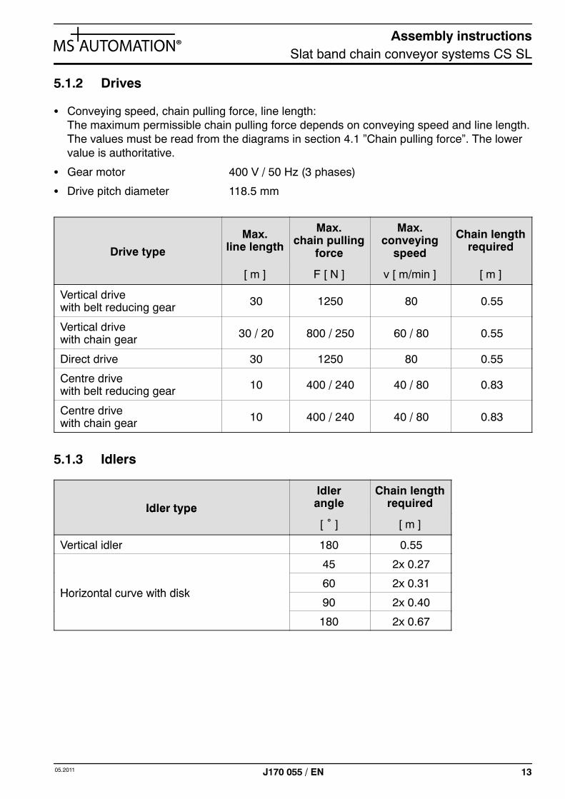
5.1.2 Drives
S Conveying speed, chain pulling force, line length:The maximum permissible chain pulling force depends on conveying speed and line length.The values must be read from the diagrams in section 4.1 ”Chain pulling force”. The lowervalue is authoritative.
S Gear motor 400 V / 50 Hz (3 phases)
S Drive pitch diameter 118.5 mm
Drive type
Max.line length
Max.chain pulling
force
Max.conveying
speed
Chain lengthrequired
[ m ] F [ N ] v [ m/min ] [ m ]
Vertical drivewith belt reducing gear 30 1250 80 0.55
Vertical drivewith chain gear 30 / 20 800 / 250 60 / 80 0.55
Direct drive 30 1250 80 0.55
Centre drivewith belt reducing gear 10 400 / 240 40 / 80 0.83
Centre drivewith chain gear 10 400 / 240 40 / 80 0.83
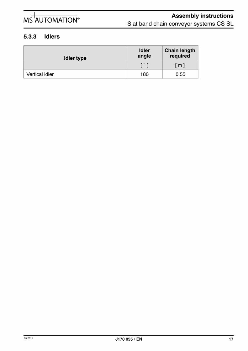
5.1.3 Idlers
Idler type
Idlerangle
Chain lengthrequiredIdler type
[ ˚ ] [ m ]
Vertical idler 180 0.55
45 2x 0.27
Horizontal curve with disk60 2x 0.31
Horizontal curve with disk90 2x 0.40
180 2x 0.67
Assembly instructionsSlat band chain conveyor systems CS SL
14 05.2011J170 055 / EN
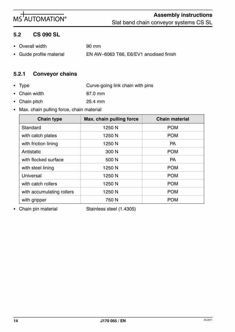
5.2 CS 090 SL
S Overall width 90 mm
S Guide profile material EN AW--6063 T66, E6/EV1 anodised finish
5.2.1 Conveyor chains
S Type Curve-going link chain with pins
S Chain width 87.0 mm
S Chain pitch 25.4 mm
S Max. chain pulling force, chain material
Chain type Max. chain pulling force Chain material
Standard 1250 N POM
with catch plates 1250 N POM
with friction lining 1250 N PA
Antistatic 300 N POM
with flocked surface 500 N PA
with steel lining 1250 N POM
Universal 1250 N POM
with catch rollers 1250 N POM
with accumulating rollers 1250 N POM
with gripper 750 N POM
S Chain pin material Stainless steel (1.4305)
Assembly instructionsSlat band chain conveyor systems CS SL
1505.2011 J170 055 / EN
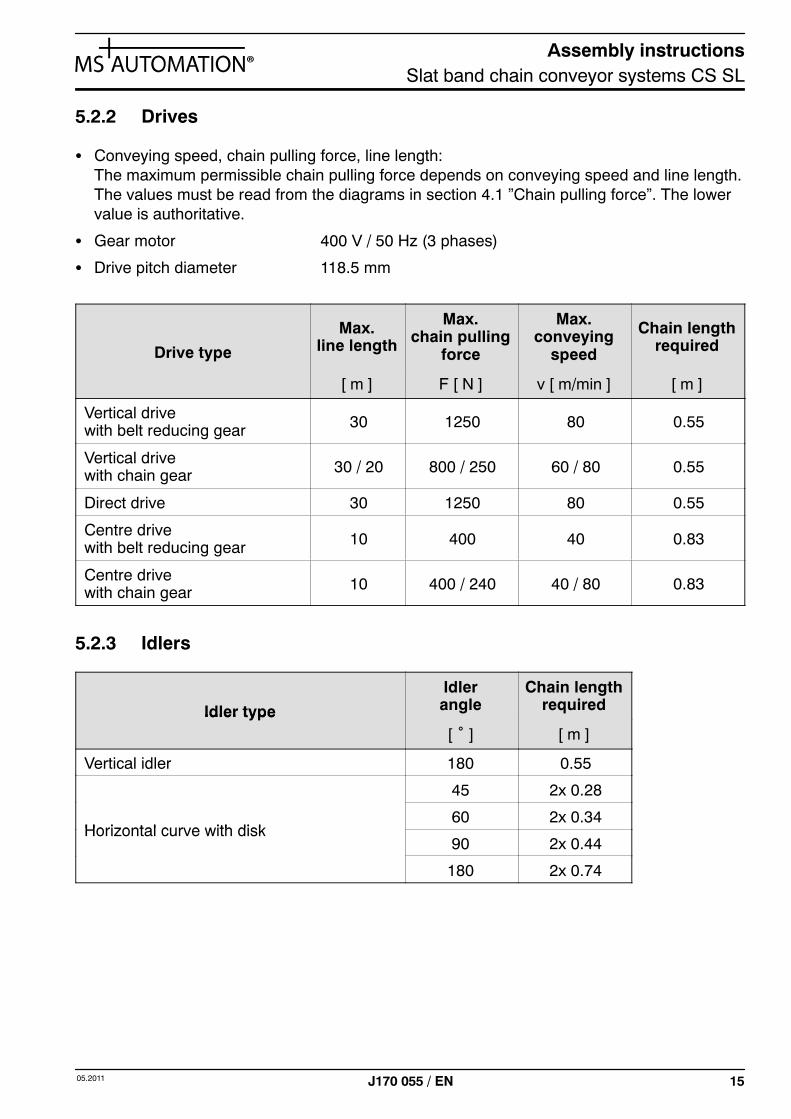
5.2.2 Drives
S Conveying speed, chain pulling force, line length:The maximum permissible chain pulling force depends on conveying speed and line length.The values must be read from the diagrams in section 4.1 ”Chain pulling force”. The lowervalue is authoritative.
S Gear motor 400 V / 50 Hz (3 phases)
S Drive pitch diameter 118.5 mm
Drive type
Max.line length
Max.chain pulling
force
Max.conveying
speed
Chain lengthrequired
[ m ] F [ N ] v [ m/min ] [ m ]
Vertical drivewith belt reducing gear 30 1250 80 0.55
Vertical drivewith chain gear 30 / 20 800 / 250 60 / 80 0.55
Direct drive 30 1250 80 0.55
Centre drivewith belt reducing gear 10 400 40 0.83
Centre drivewith chain gear 10 400 / 240 40 / 80 0.83
5.2.3 Idlers
Idler type
Idlerangle
Chain lengthrequiredIdler type
[ ˚ ] [ m ]
Vertical idler 180 0.55
45 2x 0.28
Horizontal curve with disk60 2x 0.34
Horizontal curve with disk90 2x 0.44
180 2x 0.74
Assembly instructionsSlat band chain conveyor systems CS SL
16 05.2011J170 055 / EN
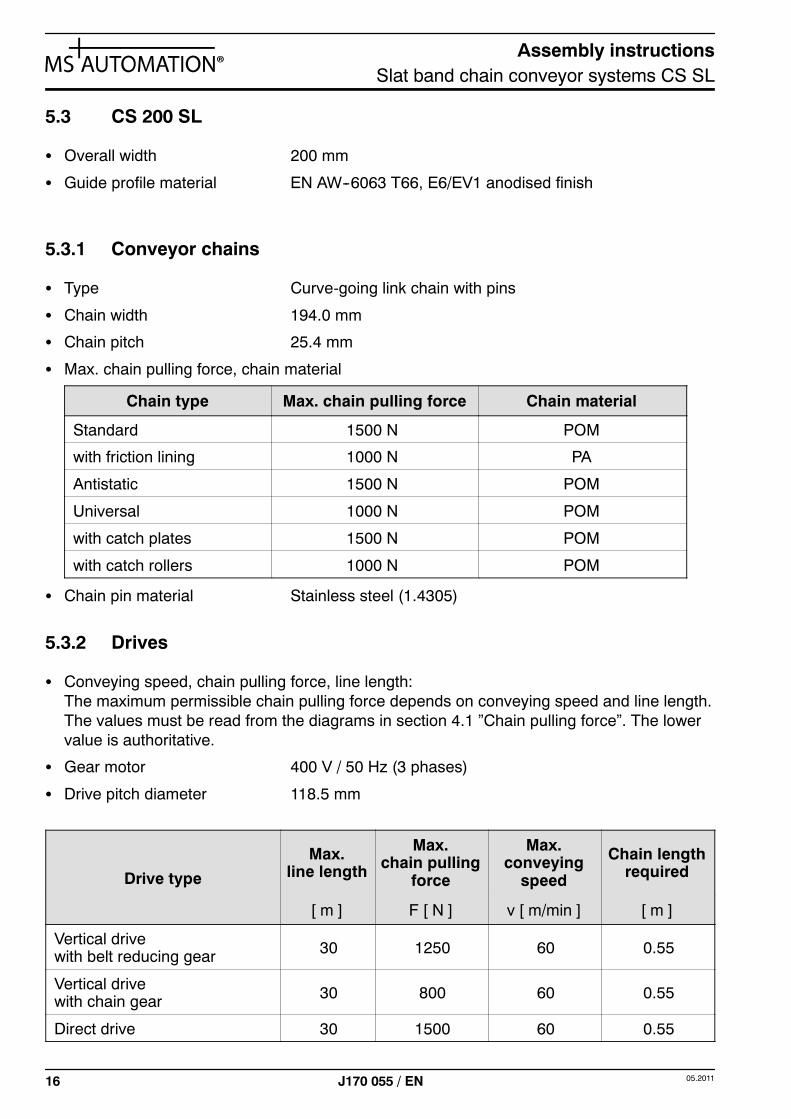
5.3 CS 200 SL
S Overall width 200 mm
S Guide profile material EN AW--6063 T66, E6/EV1 anodised finish
5.3.1 Conveyor chains
S Type Curve-going link chain with pins
S Chain width 194.0 mm
S Chain pitch 25.4 mm
S Max. chain pulling force, chain material
Chain type Max. chain pulling force Chain material
Standard 1500 N POM
with friction lining 1000 N PA
Antistatic 1500 N POM
Universal 1000 N POM
with catch plates 1500 N POM
with catch rollers 1000 N POM
S Chain pin material Stainless steel (1.4305)
5.3.2 Drives
S Conveying speed, chain pulling force, line length:The maximum permissible chain pulling force depends on conveying speed and line length.The values must be read from the diagrams in section 4.1 ”Chain pulling force”. The lowervalue is authoritative.
S Gear motor 400 V / 50 Hz (3 phases)
S Drive pitch diameter 118.5 mm
Drive type
Max.line length
Max.chain pulling
force
Max.conveying
speed
Chain lengthrequired
[ m ] F [ N ] v [ m/min ] [ m ]
Vertical drivewith belt reducing gear 30 1250 60 0.55
Vertical drivewith chain gear 30 800 60 0.55
Direct drive 30 1500 60 0.55
Assembly instructionsSlat band chain conveyor systems CS SL
1705.2011 J170 055 / EN
5.3.3 Idlers
Idler type
Idlerangle
Chain lengthrequiredIdler type
[ ˚ ] [ m ]
Vertical idler 180 0.55
Assembly instructionsSlat band chain conveyor systems CS SL
18 05.2011J170 055 / EN
6 Safety warnings
The individual machine components of the conveyor system being assembled have been desi-gned and manufactured in allowing for a risk assessment and after carefully selecting the ap-plicable harmonised standards as well as other technical specifications. As a result, they re-flect the state of the art and guarantee a maximum of safety.
However, this safety can only be achieved in working practice if all of the measures necessaryto do so are taken. Planning these measures and monitoring their implementation falls withinthe machine owner’s obligation to exercise due care.
Caution! Never work in any manner posing a safety hazard!
6.1 Owner’s obligation to exercise due care
In particular, the owner must ensure that:
S the system is only used for its intended purpose (see section 2 for details).
S the system is only operated if it is in proper working order and, in particular, that the safetydevices are regularly inspected for effective operation.
S requisite personal protective equipment is provided for and used by operating, servicingand repair personnel.
S the assembly instructions are kept in a legible state and are available in full at the place ofmachine use.
S the system is only operated, serviced and repaired by adequately qualified and authorisedpersonnel.
S these persons receive regular instruction on all matters concerning work safety and envi-ronmental protection and are familiar with the assembly instructions and, in particular, withthe safety warnings they contain.
S the system’s main switch is switched off and protected from being switched back on againwithout authorisation before conducting servicing, repair and cleaning work.
6.2 Operator’s obligation to exercise due care
In particular, the operator must ensure that:
S any identified defects with the potential to impair safe operation are reported to the ownerfor the owner to take care of rectifying them.
S the system’s main switch is switched off and protected from being switched back on againwithout authorisation before conducting cleaning work.
Assembly instructionsSlat band chain conveyor systems CS SL
1905.2011 J170 055 / EN
6.3 Potential residual risks
The conveyor system being assembled from the machine components is a machine with mo-ving parts.
Movement of the chain links presents the following potential mechanical hazards:
S Standard conveyor chain (on system CS 200 SL only): The slot-shaped gap between thechain links presents a risk of getting drawn in and crushed.
S Conveyor chains with catch plates, grippers, accumulating rollers or catch rollers, as well aschains fitted with client-specific components:
-- Risk of being pulled in and crushing hazard in the area of drive and idler units, as well assmall-radius horizontal curves.
-- Crushing hazard between railing and chain in the upper run.
-- Crushing hazard between leg joint and chain returning in the lower run.
S Line transitions (if fitted): Risk of being pulled in and crushing hazard at transition to down-stream line.
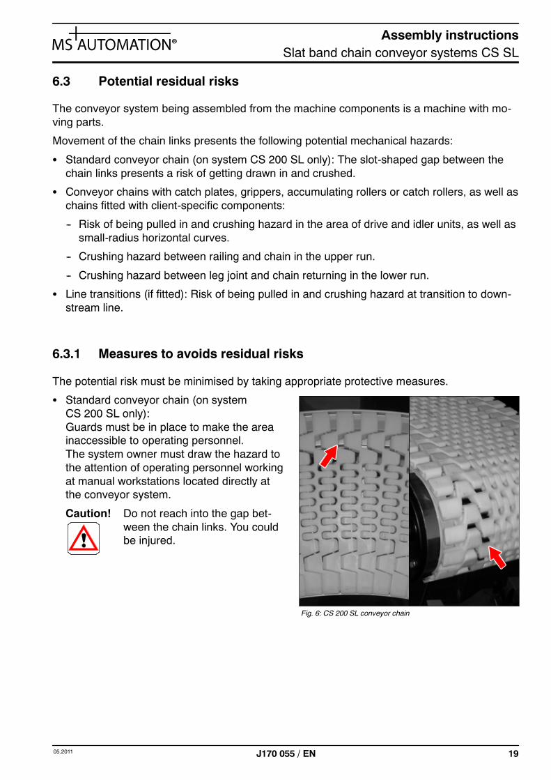
6.3.1 Measures to avoids residual risks
The potential risk must be minimised by taking appropriate protective measures.
S Standard conveyor chain (on systemCS 200 SL only):Guards must be in place to make the areainaccessible to operating personnel.The system owner must draw the hazard tothe attention of operating personnel workingat manual workstations located directly atthe conveyor system.
Caution! Do not reach into the gap bet-ween the chain links. You couldbe injured.
Fig. 6: CS 200 SL conveyor chain
Assembly instructionsSlat band chain conveyor systems CS SL
20 05.2011J170 055 / EN
S Conveyor chains with catch plates, accumulating rollers and catch rollers:When using these chain types, drive and idler units must be made inaccessible to operatingpersonnel by means of guards (e.g. protective covers). The lower run must be screened offby guards (e.g. protective grilles or protection plate) at places where manual work is carriedout directly on the conveyor system.
S Line transitions:These zones must be made accessible to operating personal by means of guards (e.g. pro-tective covers).If this is not possible, you must observe the information in Section 8.6 ”Line crossovers”.
7 Transportation and storage
Improper transportation may result in damage that can persistently impair proper workingorder.
Caution! System components must only be handled and moved by skilled personnel or pro-perly trained persons. System components must only be handled and moved usingsuitable means.
The machine components are shipped out in pre-assembled units. During transit, the compo-nents should be protected from the elements.
The site of installation or intermediate storage is of importance to proper working order. Thefollowing requirements must be met:
S Room protected from the elements (indoor space).
S Room temperature 5 -- 40°C.
S Low air humidity, low dust accumulation.
S Free from excessive vibration.
Assembly instructionsSlat band chain conveyor systems CS SL
2105.2011 J170 055 / EN
8 Assembly
The following information applies to overall widths of CS 065 SL, CS 090 SL and CS 200 SL.
The drive and idler units are delivered fully pre-assembled. The units must merely be connec-ted to the end of the line.
8.1 Installing guide profiles
8.1.1 Installing line section joints
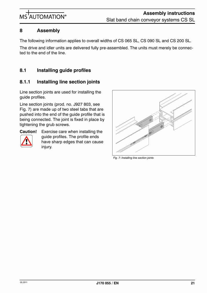
Line section joints are used for installing theguide profiles.
Line section joints (prod. no. J927 803, seeFig. 7) are made up of two steel tabs that arepushed into the end of the guide profile that isbeing connected. The joint is fixed in place bytightening the grub screws.
Caution! Exercise care when installing theguide profiles. The profile endshave sharp edges that can causeinjury.
Fig. 7: Installing line section joints
Assembly instructionsSlat band chain conveyor systems CS SL
22 05.2011J170 055 / EN
8.2 Installing function units
8.2.1 Vertical idler
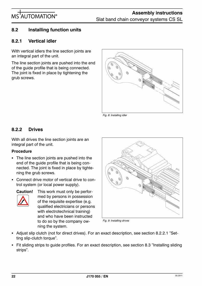
With vertical idlers the line section joints arean integral part of the unit.
The line section joints are pushed into the endof the guide profile that is being connected.The joint is fixed in place by tightening thegrub screws.
8.2.2 Drives
With all drives the line section joints are anintegral part of the unit.
Procedure
S The line section joints are pushed into theend of the guide profile that is being con-nected. The joint is fixed in place by tighte-ning the grub screws.
S Connect drive motor of vertical drive to con-trol system (or local power supply).
Caution! This work must only be perfor-med by persons in possessionof the requisite expertise (e.g.qualified electricians or personswith electrotechnical training)and who have been instructedto do so by the company ow-ning the system.
S Adjust slip clutch (not for direct drives). For an exact description, see section 8.2.2.1 ”Set-ting slip-clutch torque”.
S Fit sliding strips to guide profiles. For an exact description, see section 8.3 ”Installing slidingstrips”.
Fig. 8: Installing idler
Fig. 9: Installing drives
Assembly instructionsSlat band chain conveyor systems CS SL
2305.2011 J170 055 / EN
8.2.2.1 Setting slip-clutch torque
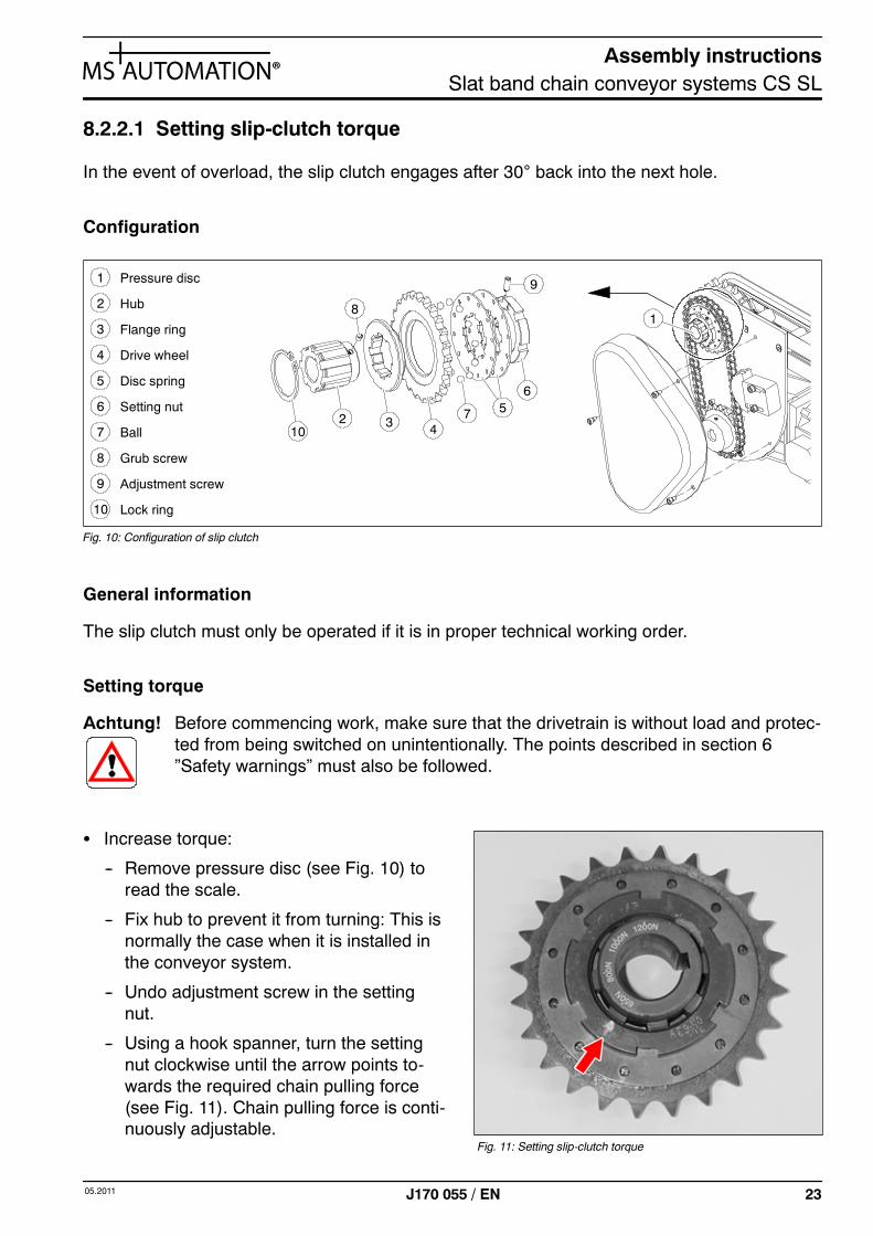
In the event of overload, the slip clutch engages after 30° back into the next hole.
Configuration
2 Hub
3 Flange ring
Drive wheel4
5 Disc spring
Setting nut6
107 Ball
Grub screw8
9 Adjustment screw
Lock ring10
1 Pressure disc
1
2 3 47 5
8
9
6
Fig. 10: Configuration of slip clutch
General information
The slip clutch must only be operated if it is in proper technical working order.
Setting torque
Achtung! Before commencing work, make sure that the drivetrain is without load and protec-ted from being switched on unintentionally. The points described in section 6”Safety warnings” must also be followed.
S Increase torque:
-- Remove pressure disc (see Fig. 10) toread the scale.
-- Fix hub to prevent it from turning: This isnormally the case when it is installed inthe conveyor system.
-- Undo adjustment screw in the settingnut.
-- Using a hook spanner, turn the settingnut clockwise until the arrow points to-wards the required chain pulling force(see Fig. 11). Chain pulling force is conti-nuously adjustable.
Fig. 11: Setting slip-clutch torque
Assembly instructionsSlat band chain conveyor systems CS SL
24 05.2011J170 055 / EN
Caution! The value set must not exceed the maximum permissible pulling force for thechain type selected (see section 5 ”Technical specifications”)!
-- After setting the chosen chain pulling force, the setting nut must be fixed in place againby tightening the adjustment screw on the threaded part of the hub.
-- Re-fit pressure disc.
S Reduce torque:
-- Remove pressure disc to read the scale.
-- Fix hub to prevent it from turning: This is normally the case when it is installed in the con-veyor system.
-- Undo adjustment screw in the setting nut.
-- Using a hook spanner, turn the setting nut anticlockwise until the arrow points towardsthe required chain pulling force (see Fig. 11). Chain pulling force is continuously adjusta-ble.
-- After setting the chosen chain pulling force, the setting nut must be fixed in place againby tightening the adjustment screw on the threaded part of the hub.
-- Re-fit pressure disc.
8.2.2.2 Reducing slip-clutch torque
On all drives with belt reducing or chain gears (except centre drives), the chain-pulling forcetransferred can be reduced by about a half by removing a disc spring (see Fig. 10).
Procedure
S Remove pressure disc.
S Fix hub to prevent it from turning: This is normally the case when it is installed in the con-veyor system.
S Undo adjustment screw in the setting nut.
S Remove setting nut with a hook spanner.
S Remove a disc spring. Achievable chain force is now about half the level printed on the unit.
S Re-fit the setting nut and, using a hook spanner, turn the setting nut anticlockwise until thearrow points towards the required chain pulling force (see Fig. 11). Chain pulling force iscontinuously adjustable.
S After setting the chosen chain pulling force, the setting nut must be fixed in place again bytightening the adjustment screw on the threaded part of the hub.
S Re-fit pressure disc.
Assembly instructionsSlat band chain conveyor systems CS SL
2505.2011 J170 055 / EN
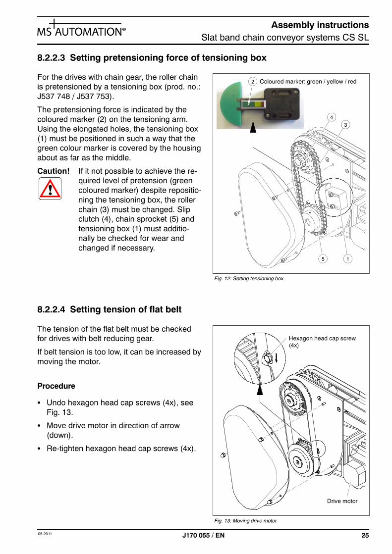
8.2.2.3 Setting pretensioning force of tensioning box
For the drives with chain gear, the roller chainis pretensioned by a tensioning box (prod. no.:J537 748 / J537 753).
The pretensioning force is indicated by thecoloured marker (2) on the tensioning arm.Using the elongated holes, the tensioning box(1) must be positioned in such a way that thegreen colour marker is covered by the housingabout as far as the middle.
Caution! If it not possible to achieve the re-quired level of pretension (greencoloured marker) despite repositio-ning the tensioning box, the rollerchain (3) must be changed. Slipclutch (4), chain sprocket (5) andtensioning box (1) must additio-nally be checked for wear andchanged if necessary.
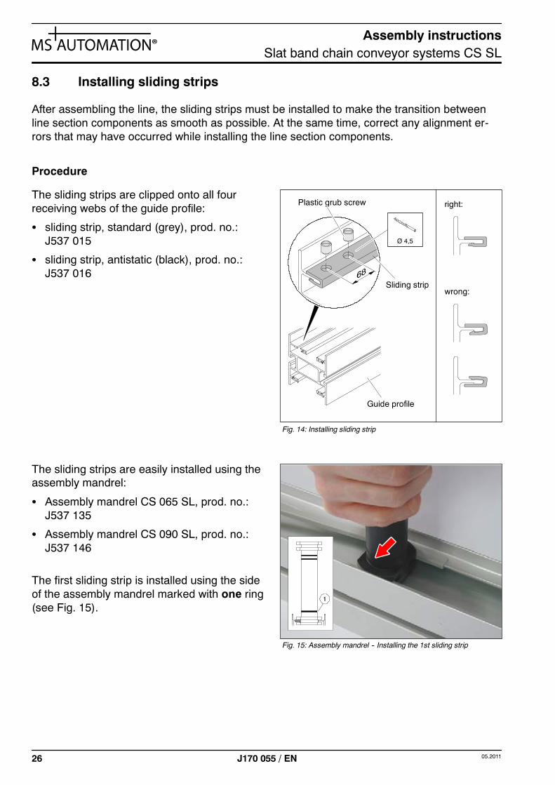
8.2.2.4 Setting tension of flat belt
The tension of the flat belt must be checkedfor drives with belt reducing gear.
If belt tension is too low, it can be increased bymoving the motor.
Procedure
S Undo hexagon head cap screws (4x), seeFig. 13.
S Move drive motor in direction of arrow(down).
S Re-tighten hexagon head cap screws (4x).
Fig. 12: Setting tensioning box
Coloured marker: green / yellow / red
15
43
2
Fig. 13: Moving drive motor
Hexagon head cap screw(4x)
Drive motor
Assembly instructionsSlat band chain conveyor systems CS SL
26 05.2011J170 055 / EN
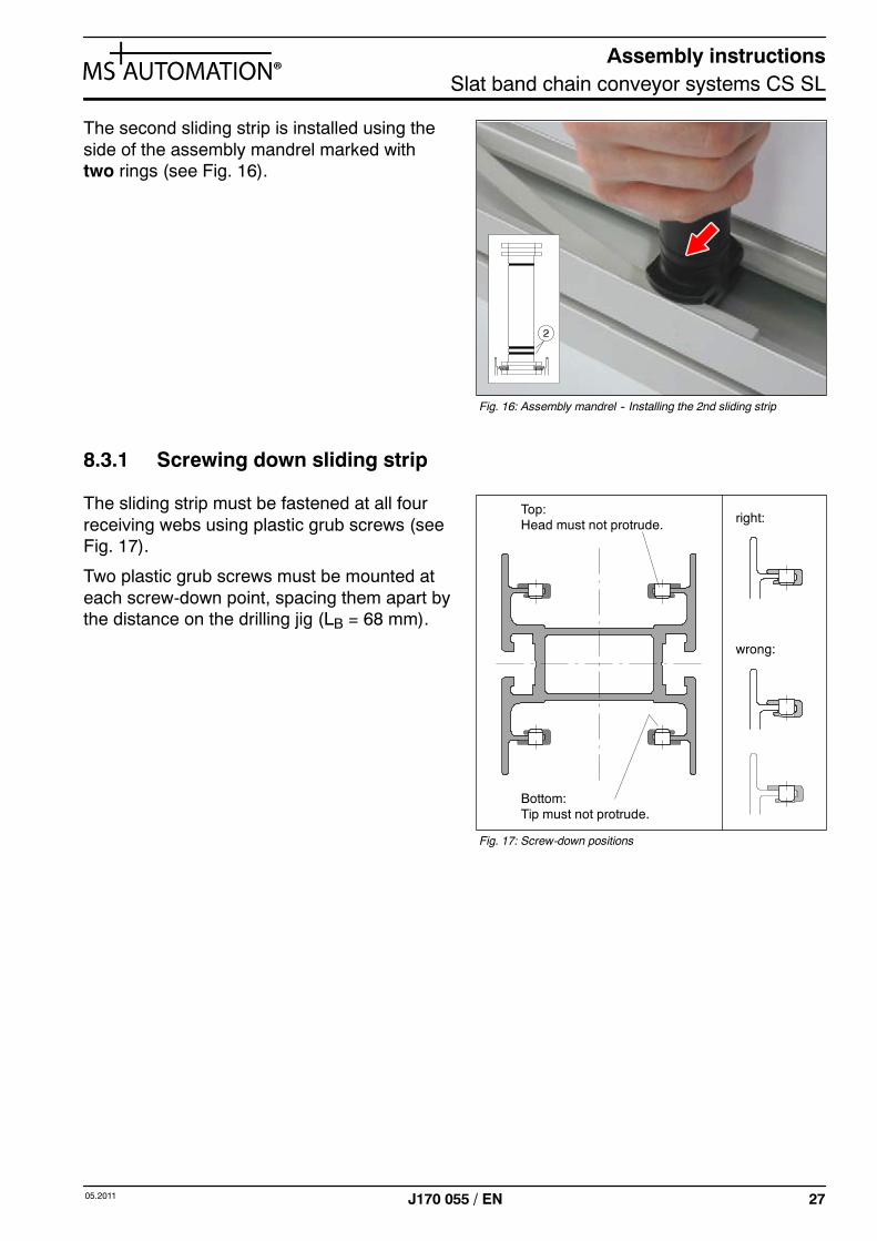
8.3 Installing sliding strips
After assembling the line, the sliding strips must be installed to make the transition betweenline section components as smooth as possible. At the same time, correct any alignment er-rors that may have occurred while installing the line section components.
Procedure
The sliding strips are clipped onto all fourreceiving webs of the guide profile:
S sliding strip, standard (grey), prod. no.:J537 015
S sliding strip, antistatic (black), prod. no.:J537 016
The sliding strips are easily installed using theassembly mandrel:
S Assembly mandrel CS 065 SL, prod. no.:J537 135
S Assembly mandrel CS 090 SL, prod. no.:J537 146
The first sliding strip is installed using the sideof the assembly mandrel marked with one ring(see Fig. 15).
Fig. 14: Installing sliding strip
right:
wrong:
Guide profile
Sliding strip
Plastic grub screw
Ø 4,5
Fig. 15: Assembly mandrel -- Installing the 1st sliding strip
Assembly instructionsSlat band chain conveyor systems CS SL
2705.2011 J170 055 / EN
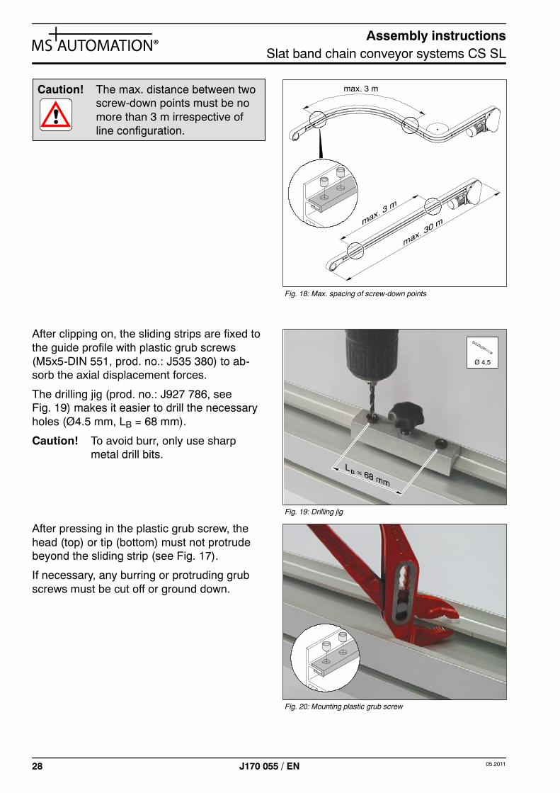
The second sliding strip is installed using theside of the assembly mandrel marked withtwo rings (see Fig. 16).
8.3.1 Screwing down sliding strip
The sliding strip must be fastened at all fourreceiving webs using plastic grub screws (seeFig. 17).
Two plastic grub screws must be mounted ateach screw-down point, spacing them apart bythe distance on the drilling jig (LB = 68 mm).
Fig. 16: Assembly mandrel -- Installing the 2nd sliding strip
Fig. 17: Screw-down positions
Top:Head must not protrude.
Bottom:Tip must not protrude.
right:
wrong:
Assembly instructionsSlat band chain conveyor systems CS SL
28 05.2011J170 055 / EN
Caution! The max. distance between twoscrew-down points must be nomore than 3 m irrespective ofline configuration.
After clipping on, the sliding strips are fixed tothe guide profile with plastic grub screws(M5x5-DIN 551, prod. no.: J535 380) to ab-sorb the axial displacement forces.
The drilling jig (prod. no.: J927 786, seeFig. 19) makes it easier to drill the necessaryholes (Ø4.5 mm, LB = 68 mm).
Caution! To avoid burr, only use sharpmetal drill bits.
After pressing in the plastic grub screw, thehead (top) or tip (bottom) must not protrudebeyond the sliding strip (see Fig. 17).
If necessary, any burring or protruding grubscrews must be cut off or ground down.
Fig. 18: Max. spacing of screw-down points
max. 3 m
Fig. 19: Drilling jig
Ø 4,5
Fig. 20: Mounting plastic grub screw
Assembly instructionsSlat band chain conveyor systems CS SL
2905.2011 J170 055 / EN
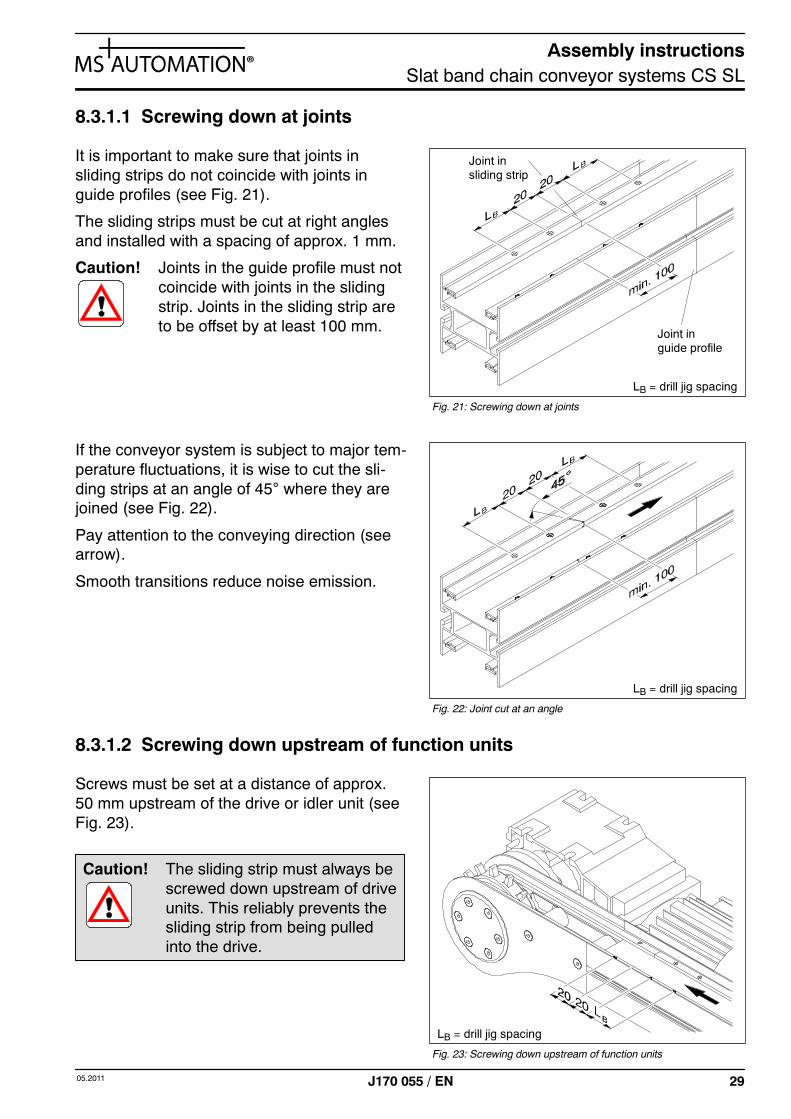
8.3.1.1 Screwing down at joints
It is important to make sure that joints insliding strips do not coincide with joints inguide profiles (see Fig. 21).
The sliding strips must be cut at right anglesand installed with a spacing of approx. 1 mm.
Caution! Joints in the guide profile must notcoincide with joints in the slidingstrip. Joints in the sliding strip areto be offset by at least 100 mm.
If the conveyor system is subject to major tem-perature fluctuations, it is wise to cut the sli-ding strips at an angle of 45° where they arejoined (see Fig. 22).
Pay attention to the conveying direction (seearrow).
Smooth transitions reduce noise emission.
8.3.1.2 Screwing down upstream of function units
Screws must be set at a distance of approx.50 mm upstream of the drive or idler unit (seeFig. 23).
Caution! The sliding strip must always bescrewed down upstream of driveunits. This reliably prevents thesliding strip from being pulledinto the drive.
Fig. 21: Screwing down at joints
Joint inguide profile
Joint insliding strip
LB = drill jig spacing
Fig. 22: Joint cut at an angle
LB = drill jig spacing
Fig. 23: Screwing down upstream of function units
LB = drill jig spacing
Assembly instructionsSlat band chain conveyor systems CS SL
30 05.2011J170 055 / EN
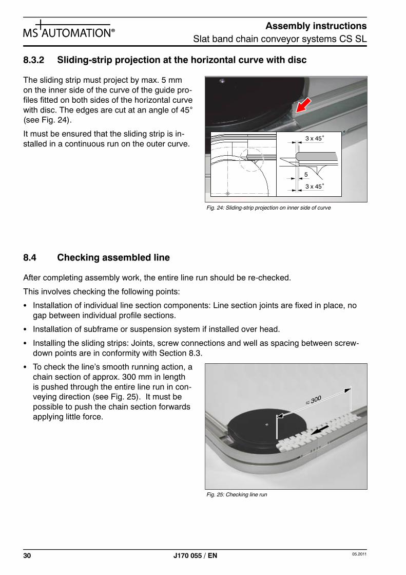
8.3.2 Sliding-strip projection at the horizontal curve with disc
The sliding strip must project by max. 5 mmon the inner side of the curve of the guide pro-files fitted on both sides of the horizontal curvewith disc. The edges are cut at an angle of 45°(see Fig. 24).
It must be ensured that the sliding strip is in-stalled in a continuous run on the outer curve.
8.4 Checking assembled line
After completing assembly work, the entire line run should be re-checked.
This involves checking the following points:
S Installation of individual line section components: Line section joints are fixed in place, nogap between individual profile sections.
S Installation of subframe or suspension system if installed over head.
S Installing the sliding strips: Joints, screw connections and well as spacing between screw-down points are in conformity with Section 8.3.
S To check the line’s smooth running action, achain section of approx. 300 mm in lengthis pushed through the entire line run in con-veying direction (see Fig. 25). It must bepossible to push the chain section forwardsapplying little force.
Fig. 24: Sliding-strip projection on inner side of curve
5
3 x 45˚
3 x 45˚
Fig. 25: Checking line run
Assembly instructionsSlat band chain conveyor systems CS SL
3105.2011 J170 055 / EN
8.5 Drawing conveyor chain into the line
The chain assembly unit allows you to draw the chain into the assembled line.
The unit can be mounted at any point in the line. Installation takes place using the line sectionjoints belonging to the unit. For an exact description, see Section 8.1.1 ”Installing line sectionjoints”.
Use of the chain assembly aid facilitates feeding the conveyor chain into the line:
S Chain assembly aid CS 065 SL, prod. no.: J927 823
S Chain assembly aid CS 090 SL, prod. no.: J927 824
S Chain assembly aid CS 200 SL, prod. no.: J927 821
The split-pin driver helps to fit/remove the chain pin: prod. no. J537 131.
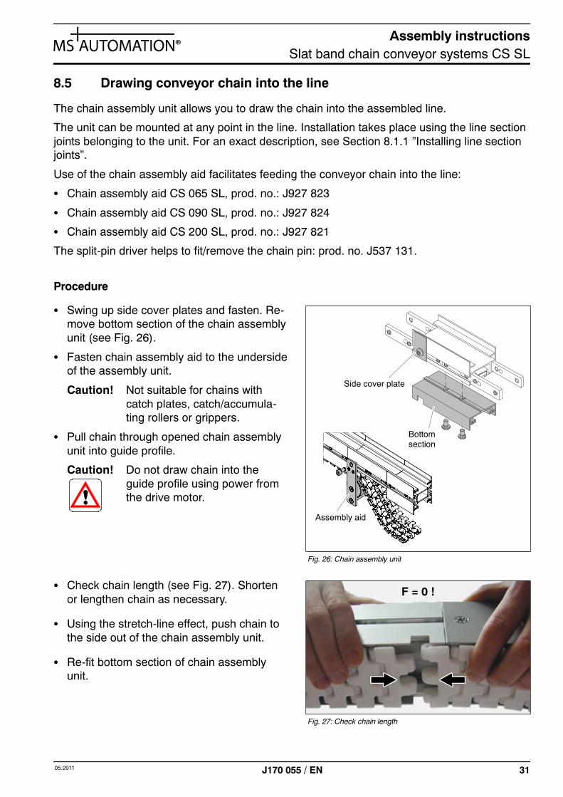
Procedure
S Swing up side cover plates and fasten. Re-move bottom section of the chain assemblyunit (see Fig. 26).
S Fasten chain assembly aid to the undersideof the assembly unit.
Caution! Not suitable for chains withcatch plates, catch/accumula-ting rollers or grippers.
S Pull chain through opened chain assemblyunit into guide profile.
Caution! Do not draw chain into theguide profile using power fromthe drive motor.
S Check chain length (see Fig. 27). Shortenor lengthen chain as necessary.
S Using the stretch-line effect, push chain tothe side out of the chain assembly unit.
S Re-fit bottom section of chain assemblyunit.
Side cover plate
Bottomsection
Assembly aid
Fig. 26: Chain assembly unit
Fig. 27: Check chain length
F = 0 !
Assembly instructionsSlat band chain conveyor systems CS SL
32 05.2011J170 055 / EN
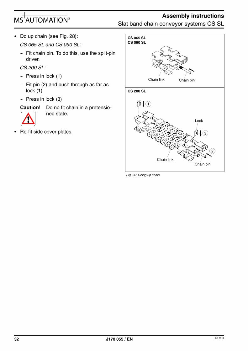
S Do up chain (see Fig. 28):
CS 065 SL and CS 090 SL:
-- Fit chain pin. To do this, use the split-pindriver.
CS 200 SL:
-- Press in lock (1)
-- Fit pin (2) and push through as far aslock (1)
-- Press in lock (3)
Caution! Do no fit chain in a pretensio-ned state.
S Re-fit side cover plates.
Fig. 28: Doing up chain
Chain pin
Lock
Chain link
CS 065 SL
CS 200 SL
2
3
1
Chain pinChain link
CS 090 SL
Assembly instructionsSlat band chain conveyor systems CS SL
3305.2011 J170 055 / EN
8.6 Line crossovers
8.6.1 Roll transfer
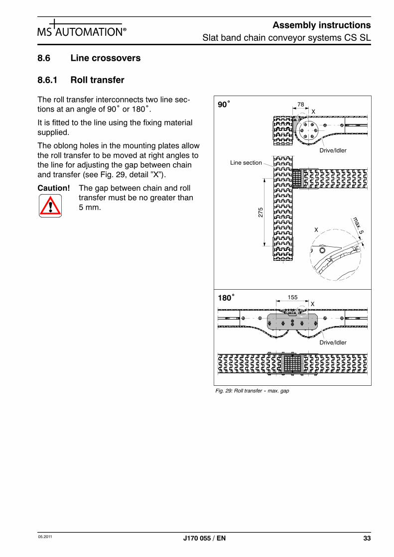
The roll transfer interconnects two line sec-tions at an angle of 90˚ or 180˚.
It is fitted to the line using the fixing materialsupplied.
The oblong holes in the mounting plates allowthe roll transfer to be moved at right angles tothe line for adjusting the gap between chainand transfer (see Fig. 29, detail ”X”).
Caution! The gap between chain and rolltransfer must be no greater than5 mm.
Fig. 29: Roll transfer -- max. gap
90˚
180˚
X
X
X
Drive/Idler
Line section
78
155
275
Drive/Idler
Assembly instructionsSlat band chain conveyor systems CS SL
34 05.2011J170 055 / EN
8.6.2 Crossover with railing
In this crossover option, two line sections are connected with a continuous railing.
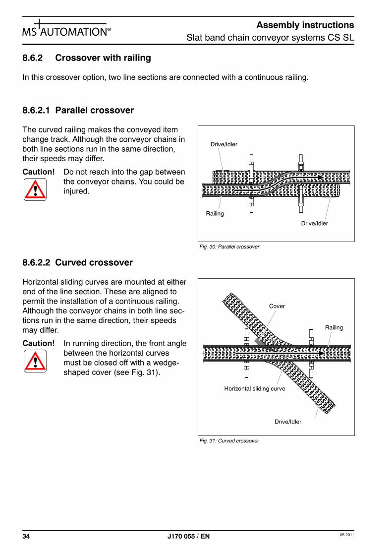
8.6.2.1 Parallel crossover
The curved railing makes the conveyed itemchange track. Although the conveyor chains inboth line sections run in the same direction,their speeds may differ.
Caution! Do not reach into the gap betweenthe conveyor chains. You could beinjured.
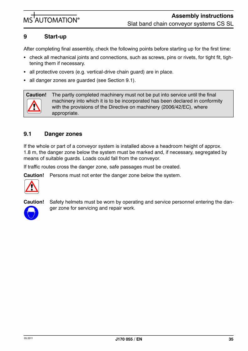
8.6.2.2 Curved crossover
Horizontal sliding curves are mounted at eitherend of the line section. These are aligned topermit the installation of a continuous railing.Although the conveyor chains in both line sec-tions run in the same direction, their speedsmay differ.
Caution! In running direction, the front anglebetween the horizontal curvesmust be closed off with a wedge-shaped cover (see Fig. 31).
Fig. 30: Parallel crossover
Drive/Idler
Drive/Idler
Railing
Fig. 31: Curved crossover
Drive/Idler
Railing
Horizontal sliding curve
Cover
Assembly instructionsSlat band chain conveyor systems CS SL
3505.2011 J170 055 / EN
9 Start-up
After completing final assembly, check the following points before starting up for the first time:
S check all mechanical joints and connections, such as screws, pins or rivets, for tight fit, tigh-tening them if necessary.
S all protective covers (e.g. vertical-drive chain guard) are in place.
S all danger zones are guarded (see Section 9.1).
Caution! The partly completed machinery must not be put into service until the finalmachinery into which it is to be incorporated has been declared in conformitywith the provisions of the Directive on machinery (2006/42/EC), whereappropriate.
9.1 Danger zones
If the whole or part of a conveyor system is installed above a headroom height of approx.1.8 m, the danger zone below the system must be marked and, if necessary, segregated bymeans of suitable guards. Loads could fall from the conveyor.
If traffic routes cross the danger zone, safe passages must be created.
Caution! Persons must not enter the danger zone below the system.
Caution! Safety helmets must be worn by operating and service personnel entering the dan-ger zone for servicing and repair work.
Assembly instructionsSlat band chain conveyor systems CS SL
36 05.2011J170 055 / EN
9.2 Normal operation
It is important to ensure that the servicing intervals for normal operation (see Section 10 ”Clea-ning, servicing and maintenance”) are observed.
The ”Safety precautions” described in Section 6 must also be followed.
Caution! Never work in any manner posing a safety hazard!
Only operate the system if all guards and safety equipment are in place and in pro-per working order!
Check the system for externally visible damage or deficiencies at least once everyshift!Immediately report any changes that have occurred (including operating beha-viour) to the department / person responsible!Immediately shut down and immobilise the system!
In the event of malfunctions, immediately shut down and immobilise thesystem!Immediately take steps to rectify faults!
Before switching the system on/setting the system in motion, make sure that no-body is exposed to any danger when the system starts running!
9.3 Hot motors
Motors in permanent operation heat up to high temperatures.
Caution! Do not touch motor casing!You could burn your skin!
Beware ofhot surface

Assembly instructionsSlat band chain conveyor systems CS SL
3705.2011 J170 055 / EN
10 Maintenance, cleaning and servicing
The entire conveyor system must be checked at regular intervals to ensure trouble-free, quietoperation.
Depending on the length of conveyor run and loads carried by the conveyor system, servicingmust be carried out at intervals of 250 to a maximum of 500 operating hours.
The servicing and maintenance work listed below is intended to contribute towards extendingthe machine’s useful life under high-capacity use and help prevent accidents.
Caution! Only perform this work if you are qualified to do so. Before commencing work, readSection 6 ”Safety warnings”.
The following work must be carried out at regular intervals:
S The entire conveyor system must be protected from dirt.
S Chain and sliding strips in particular must be kept free of dirt, pieces of broken glass, sandetc.
Caution! Always wear protective goggles when cleaning the system with compressed air.
S Regularly clean off dirt with steam, water or soapy water. Cleaning agents may be used witha pH value of between 4.5 and 9.0.
Caution! Due to their caustic effect, cleaners containing solvent must not be used onchain and sliding strips.
S Irregularities on guides and sliding strips must be eliminated to ensure that the chain runssmoothly.
S Check conveyor chain for damage: Defects, such as broken chain links or high levels of ab-rasion, may occur if actual pulling force is higher than permissible pulling force. This mayalso result in the drive chain sprocket slipping.
S Check conveyor chain for elongation: The chain may lengthen under load and must beshortened if necessary. For further details, see Section 10.4 ”Shortening or renewing con-veyor chain”.
S Check sliding strips for wear: If grooving or cracking occurs, the sliding strip must bechanged.
S Check the points at which the sliding strips are screwed down. These may tear out underheavy loads. The sliding-strip section concerned must be changed and screwed back inplace more frequently.
S Drives with chain gears: Lubricate roller chain. For further details, see Section 10.2 ”Driveunits with chain gear”.
S Drives with belt reducing gear: Re-tension flat belt. For further details, see Section 10.3”Drive units with belt reducing gear”.
S Check all wear parts (conveyor chain, chain wheels, chain guides, bearings, idler wheelsetc.) for proper working order.
Assembly instructionsSlat band chain conveyor systems CS SL
38 05.2011J170 055 / EN
10.1 Conveyor chain lubrication
CS SL conveyor systems can in general be operated without lubrication. This is made possibleby the excellent material properties of the sliding strip.
10.2 Drive units with chain gear
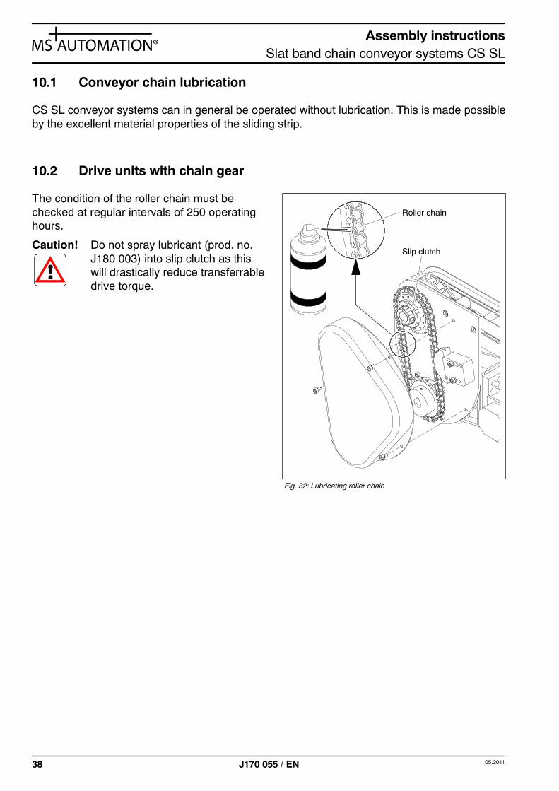
The condition of the roller chain must bechecked at regular intervals of 250 operatinghours.
Caution! Do not spray lubricant (prod. no.J180 003) into slip clutch as thiswill drastically reduce transferrabledrive torque.
Fig. 32: Lubricating roller chain
Slip clutch
Roller chain
Assembly instructionsSlat band chain conveyor systems CS SL
3905.2011 J170 055 / EN
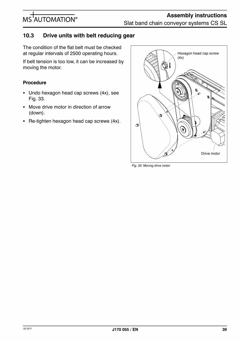
10.3 Drive units with belt reducing gear
The condition of the flat belt must be checkedat regular intervals of 2500 operating hours.
If belt tension is too low, it can be increased bymoving the motor.
Procedure
S Undo hexagon head cap screws (4x), seeFig. 33.
S Move drive motor in direction of arrow(down).
S Re-tighten hexagon head cap screws (4x).
Fig. 33: Moving drive motor
Hexagon head cap screw(4x)
Drive motor
Assembly instructionsSlat band chain conveyor systems CS SL
40 05.2011J170 055 / EN
10.4 Shortening or renewing conveyor chain
In case of elongation, wear or irreparable damage, the entire chain or only individual chainlinks may be removed and renewed.
To remove the chain or individual links, the chain loop must be undone with the aid of thechain assembly unit.
Use of the chain assembly aid facilitates feeding the conveyor chain into the line:
S Chain assembly aid CS 065 SL, prod. no.: J927 823
S Chain assembly aid CS 090 SL, prod. no.: J927 824
S Chain assembly aid CS 200 SL, prod. no.: J927 821
The split-pin driver helps to fit/remove the chain pin: prod. no. J537 131.
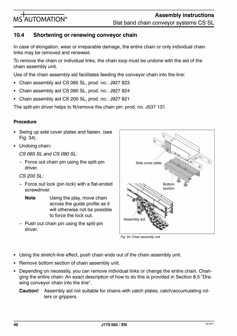
Procedure
S Swing up side cover plates and fasten. (seeFig. 34).
S Undoing chain:
CS 065 SL and CS 090 SL:
-- Force out chain pin using the split-pindriver.
CS 200 SL:
-- Force out lock (pin lock) with a flat-endedscrewdriver.
Note Using the play, move chainacross the guide profile as itwill otherwise not be possibleto force the lock out.
-- Push out chain pin using the split-pindriver.
S Using the stretch-line effect, push chain ends out of the chain assembly unit.
S Remove bottom section of chain assembly unit.
S Depending on necessity, you can remove individual links or change the entire chain. Chan-ging the entire chain: An exact description of how to do this is provided in Section 8.5 ”Dra-wing conveyor chain into the line”.
Caution! Assembly aid not suitable for chains with catch plates, catch/accumulating rol-lers or grippers.
Assembly aid
Fig. 34: Chain assembly unit
Side cover plate
Bottomsection
Assembly instructionsSlat band chain conveyor systems CS SL
4105.2011 J170 055 / EN
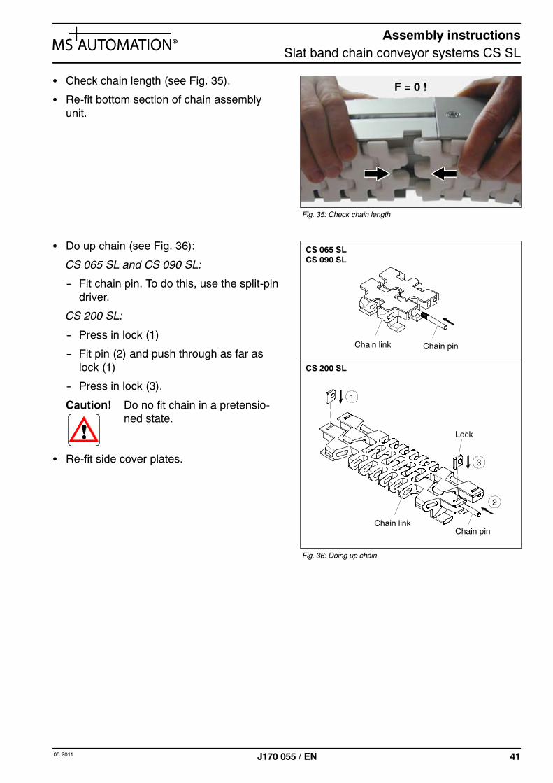
S Check chain length (see Fig. 35).
S Re-fit bottom section of chain assemblyunit.
S Do up chain (see Fig. 36):
CS 065 SL and CS 090 SL:
-- Fit chain pin. To do this, use the split-pindriver.
CS 200 SL:
-- Press in lock (1)
-- Fit pin (2) and push through as far aslock (1)
-- Press in lock (3).
Caution! Do no fit chain in a pretensio-ned state.
S Re-fit side cover plates.
Fig. 35: Check chain length
F = 0 !
Fig. 36: Doing up chain
Chain pin
Lock
Chain link
CS 065 SL
CS 200 SL
2
3
1
Chain pinChain link
CS 090 SL
Assembly instructionsSlat band chain conveyor systems CS SL
42 05.2011J170 055 / EN
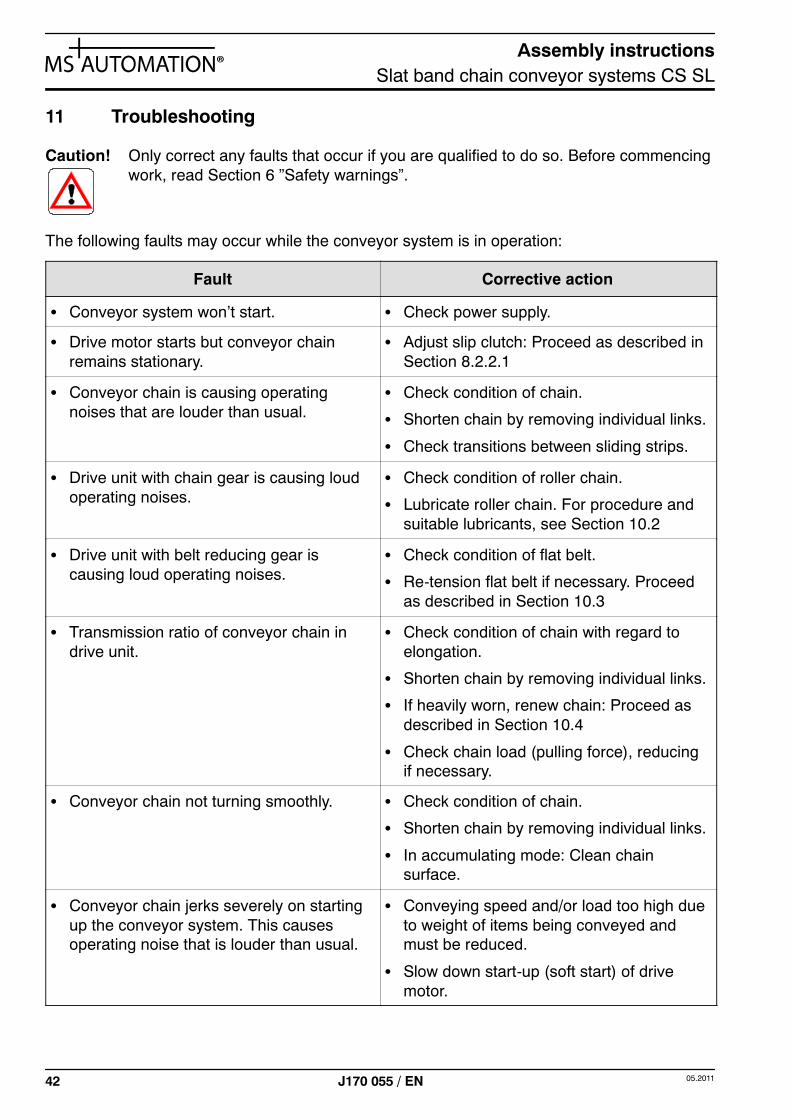
11 Troubleshooting
Caution! Only correct any faults that occur if you are qualified to do so. Before commencingwork, read Section 6 ”Safety warnings”.
The following faults may occur while the conveyor system is in operation:
Fault Corrective action
S Conveyor system won’t start. S Check power supply.
S Drive motor starts but conveyor chainremains stationary.
S Adjust slip clutch: Proceed as described inSection 8.2.2.1
S Conveyor chain is causing operatingnoises that are louder than usual.
S Check condition of chain.
S Shorten chain by removing individual links.
S Check transitions between sliding strips.
S Drive unit with chain gear is causing loudoperating noises.
S Check condition of roller chain.
S Lubricate roller chain. For procedure andsuitable lubricants, see Section 10.2
S Drive unit with belt reducing gear iscausing loud operating noises.
S Check condition of flat belt.
S Re-tension flat belt if necessary. Proceedas described in Section 10.3
S Transmission ratio of conveyor chain indrive unit.
S Check condition of chain with regard toelongation.
S Shorten chain by removing individual links.
S If heavily worn, renew chain: Proceed asdescribed in Section 10.4
S Check chain load (pulling force), reducingif necessary.
S Conveyor chain not turning smoothly. S Check condition of chain.
S Shorten chain by removing individual links.
S In accumulating mode: Clean chainsurface.
S Conveyor chain jerks severely on startingup the conveyor system. This causesoperating noise that is louder than usual.
S Conveying speed and/or load too high dueto weight of items being conveyed andmust be reduced.
S Slow down start-up (soft start) of drivemotor.
Assembly instructionsSlat band chain conveyor systems CS SL
4305.2011 J170 055 / EN
12 Taking out of operation
To take the conveyor system out of operation, disconnect the drive motor from the control sy-stem (or local power supply).
Caution! This work must only be performed by persons in possession of the requisite exper-tise (e.g. qualified electricians or persons with electrotechnical training) and whohave been instructed to do so by the company owning the system.
To store the conveyor system, following the points described in Section 7 ”Transportation andstorage”. This is important, particularly in relation to putting the system back into operation at alater date.
13 Disposal
The conveyor system is disassembled at the end of its useful life. Doing so, individual compo-nents should be dismantled by skilled personnel or properly instructed persons and reusablematerials recycled.
Caution! Any hazardous materials involved must be disposed of in the proper manner.
Assembly instructionsSlat band chain conveyor systems CS SL
44 05.2011J170 055 / EN
14 Appendix: Drawings and parts lists
Drives and idlers
The following figures show the configuration of drive and idler units in detail.The parts lists contain all wearing parts that can be reordered individually.
Conveyor chain and sliding strip
Conveyor chain and sliding strip are defined as wearing parts.
Assembly instructionsSlat band chain conveyor systems CS SL
4505.2011 J170 055 / EN
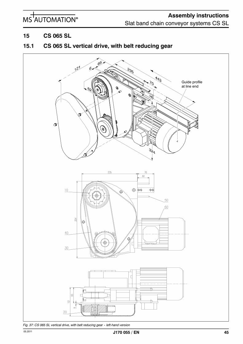
15 CS 065 SL
15.1 CS 065 SL vertical drive, with belt reducing gear
Guide profileat line end
Fig. 37: CS 065 SL vertical drive, with belt reducing gear -- left-hand version
Assembly instructionsSlat band chain conveyor systems CS SL
46 05.2011J170 055 / EN
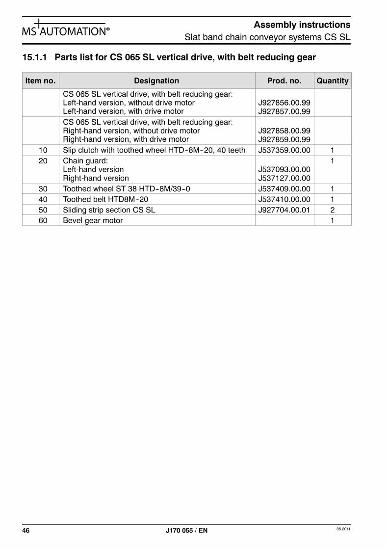
15.1.1 Parts list for CS 065 SL vertical drive, with belt reducing gear
Item no. Designation Prod. no. Quantity
CS 065 SL vertical drive, with belt reducing gear:Left-hand version, without drive motorLeft-hand version, with drive motor
J927856.00.99J927857.00.99
CS 065 SL vertical drive, with belt reducing gear:Right-hand version, without drive motorRight-hand version, with drive motor
J927858.00.99J927859.00.99
10 Slip clutch with toothed wheel HTD--8M--20, 40 teeth J537359.00.00 120 Chain guard:
Left-hand versionRight-hand version
J537093.00.00J537127.00.00
1
30 Toothed wheel ST 38 HTD--8M/39--0 J537409.00.00 140 Toothed belt HTD8M--20 J537410.00.00 150 Sliding strip section CS SL J927704.00.01 260 Bevel gear motor 1
Assembly instructionsSlat band chain conveyor systems CS SL
4705.2011 J170 055 / EN
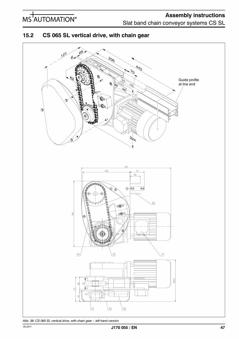
15.2 CS 065 SL vertical drive, with chain gear
Guide profileat line end
Abb. 38: CS 065 SL vertical drive, with chain gear -- left-hand version
Assembly instructionsSlat band chain conveyor systems CS SL
48 05.2011J170 055 / EN
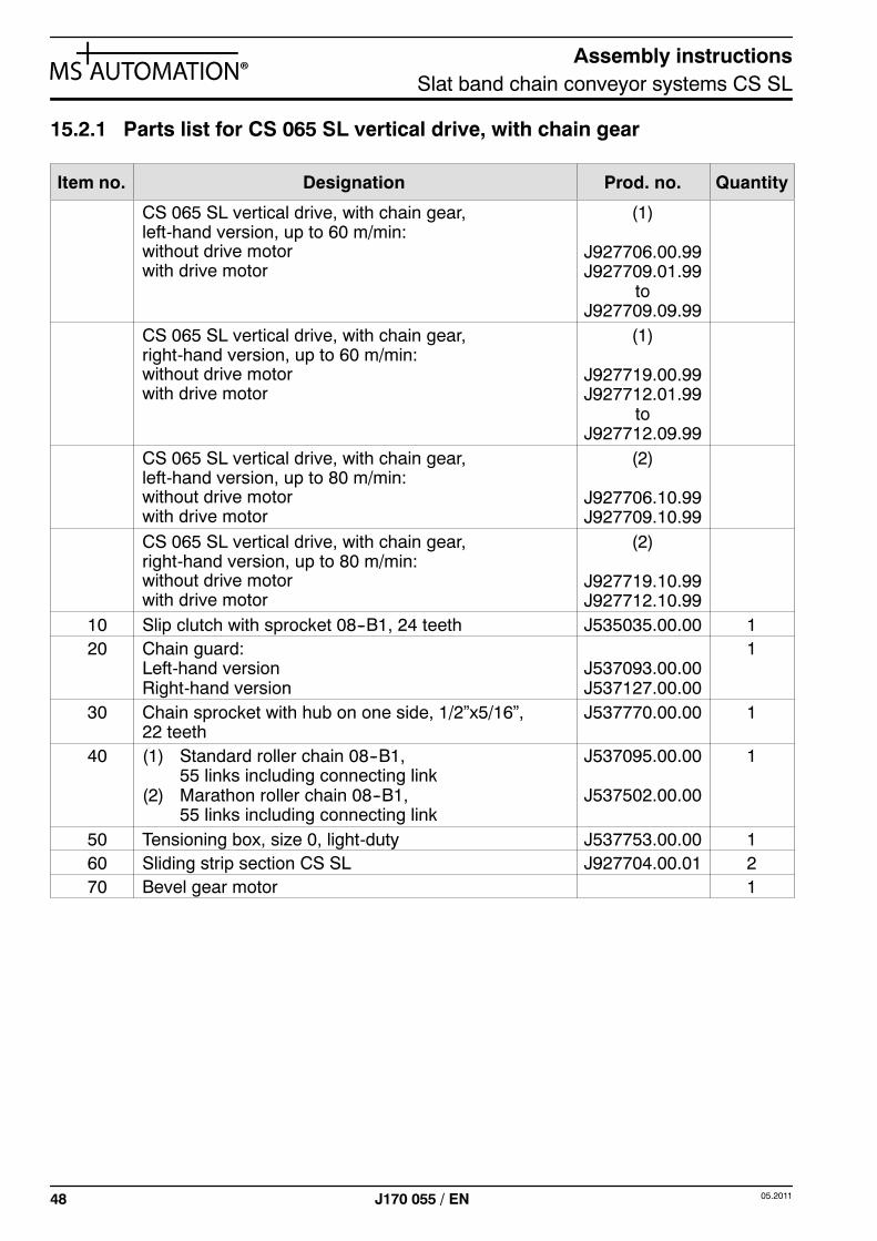
15.2.1 Parts list for CS 065 SL vertical drive, with chain gear
Item no. Designation Prod. no. Quantity
CS 065 SL vertical drive, with chain gear,left-hand version, up to 60 m/min:without drive motorwith drive motor
(1)
J927706.00.99J927709.01.99
toJ927709.09.99
CS 065 SL vertical drive, with chain gear,right-hand version, up to 60 m/min:without drive motorwith drive motor
(1)
J927719.00.99J927712.01.99
toJ927712.09.99
CS 065 SL vertical drive, with chain gear,left-hand version, up to 80 m/min:without drive motorwith drive motor
(2)
J927706.10.99J927709.10.99
CS 065 SL vertical drive, with chain gear,right-hand version, up to 80 m/min:without drive motorwith drive motor
(2)
J927719.10.99J927712.10.99
10 Slip clutch with sprocket 08--B1, 24 teeth J535035.00.00 120 Chain guard:
Left-hand versionRight-hand version
J537093.00.00J537127.00.00
1
30 Chain sprocket with hub on one side, 1/2”x5/16”,22 teeth
J537770.00.00 1
40 (1) Standard roller chain 08--B1,55 links including connecting link
(2) Marathon roller chain 08--B1,55 links including connecting link
J537095.00.00
J537502.00.00
1
50 Tensioning box, size 0, light-duty J537753.00.00 160 Sliding strip section CS SL J927704.00.01 270 Bevel gear motor 1
Assembly instructionsSlat band chain conveyor systems CS SL
4905.2011 J170 055 / EN
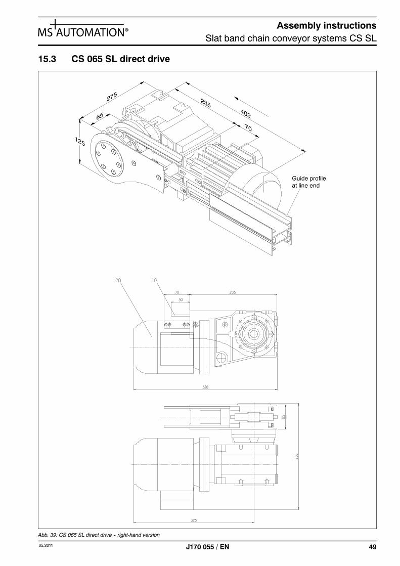
15.3 CS 065 SL direct drive
Guide profileat line end
Abb. 39: CS 065 SL direct drive -- right-hand version
Assembly instructionsSlat band chain conveyor systems CS SL
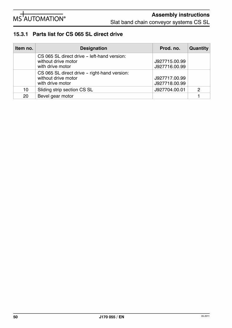
50 05.2011J170 055 / EN
15.3.1 Parts list for CS 065 SL direct drive
Item no. Designation Prod. no. Quantity
CS 065 SL direct drive -- left-hand version:without drive motorwith drive motor
J927715.00.99J927716.00.99
CS 065 SL direct drive -- right-hand version:without drive motorwith drive motor
J927717.00.99J927718.00.99
10 Sliding strip section CS SL J927704.00.01 220 Bevel gear motor 1
Assembly instructionsSlat band chain conveyor systems CS SL
5105.2011 J170 055 / EN
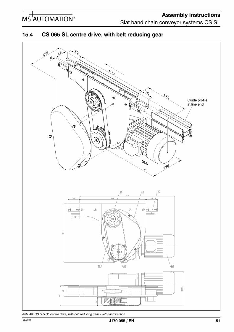
15.4 CS 065 SL centre drive, with belt reducing gear
Guide profileat line end
Abb. 40: CS 065 SL centre drive, with belt reducing gear -- left-hand version

Assembly instructionsSlat band chain conveyor systems CS SL
52 05.2011J170 055 / EN
15.4.1 Parts list for CS 065 SL centre drive, with belt reducing gear
Item no. Designation Prod. no. Quantity
CS 065 SL centre drive, with belt reducing gear:Left-hand version, without drive motorLeft-hand version, with drive motor
J927860.00.99J927861.00.99
CS 065 SL centre drive, with belt reducing gear:Right-hand version, without drive motorRight-hand version, with drive motor
J927862.00.99J927863.00.99
10 Slip clutch with toothed wheel HTD--8M--20, 40 teeth J537360.00.00 120 Chain guard:
Left-hand versionRight-hand version
J537093.00.00J537127.00.00
1
30 Toothed wheel ST 38 HTD--8M/39--0 J537409.00.00 140 Toothed belt HTD8M--20 J537410.00.00 150 Sliding strip section CS SL J927789.00.01 260 Bevel gear motor 1
Assembly instructionsSlat band chain conveyor systems CS SL
5305.2011 J170 055 / EN
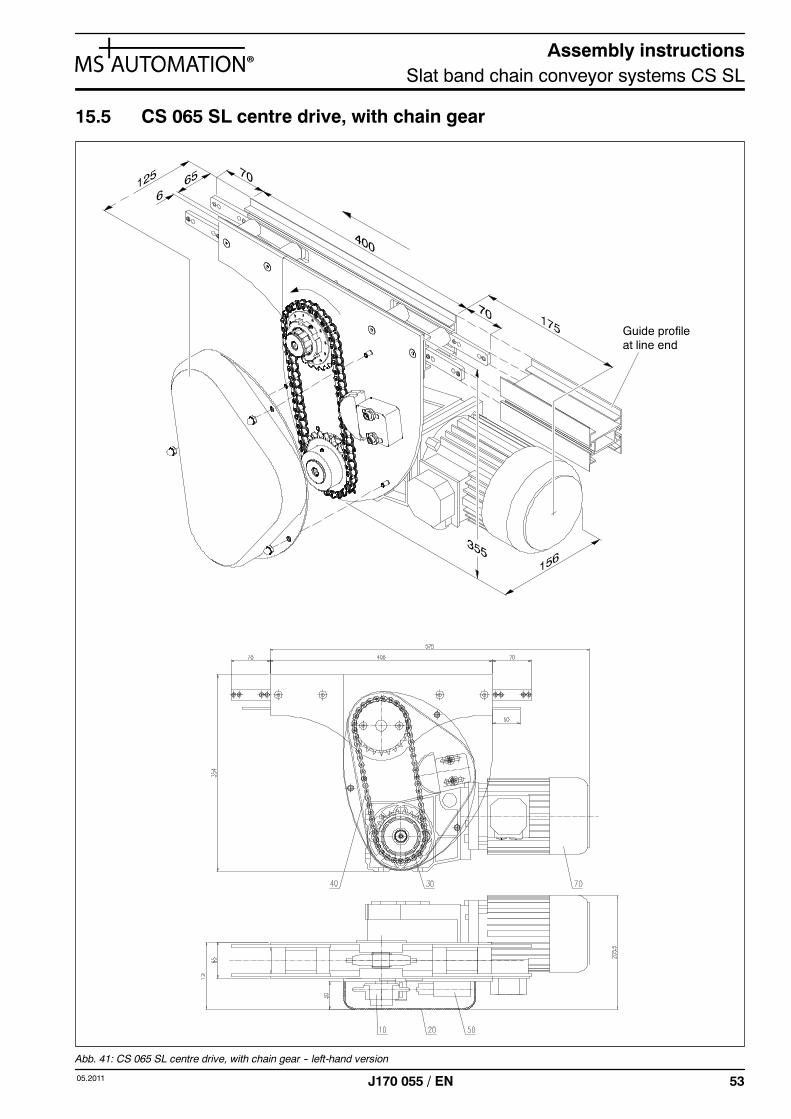
15.5 CS 065 SL centre drive, with chain gear
Guide profileat line end
Abb. 41: CS 065 SL centre drive, with chain gear -- left-hand version
Assembly instructionsSlat band chain conveyor systems CS SL
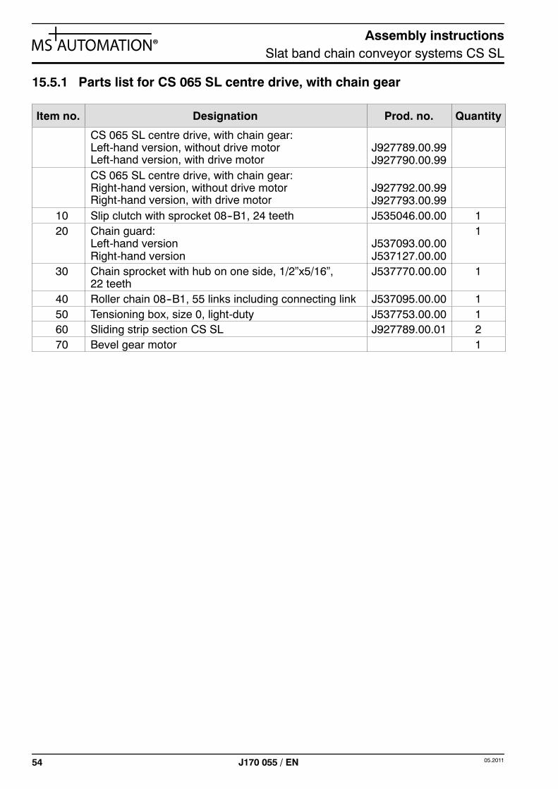
54 05.2011J170 055 / EN
15.5.1 Parts list for CS 065 SL centre drive, with chain gear
Item no. Designation Prod. no. Quantity
CS 065 SL centre drive, with chain gear:Left-hand version, without drive motorLeft-hand version, with drive motor
J927789.00.99J927790.00.99
CS 065 SL centre drive, with chain gear:Right-hand version, without drive motorRight-hand version, with drive motor
J927792.00.99J927793.00.99
10 Slip clutch with sprocket 08--B1, 24 teeth J535046.00.00 120 Chain guard:
Left-hand versionRight-hand version
J537093.00.00J537127.00.00
1
30 Chain sprocket with hub on one side, 1/2”x5/16”,22 teeth
J537770.00.00 1
40 Roller chain 08--B1, 55 links including connecting link J537095.00.00 150 Tensioning box, size 0, light-duty J537753.00.00 160 Sliding strip section CS SL J927789.00.01 270 Bevel gear motor 1
Assembly instructionsSlat band chain conveyor systems CS SL
5505.2011 J170 055 / EN
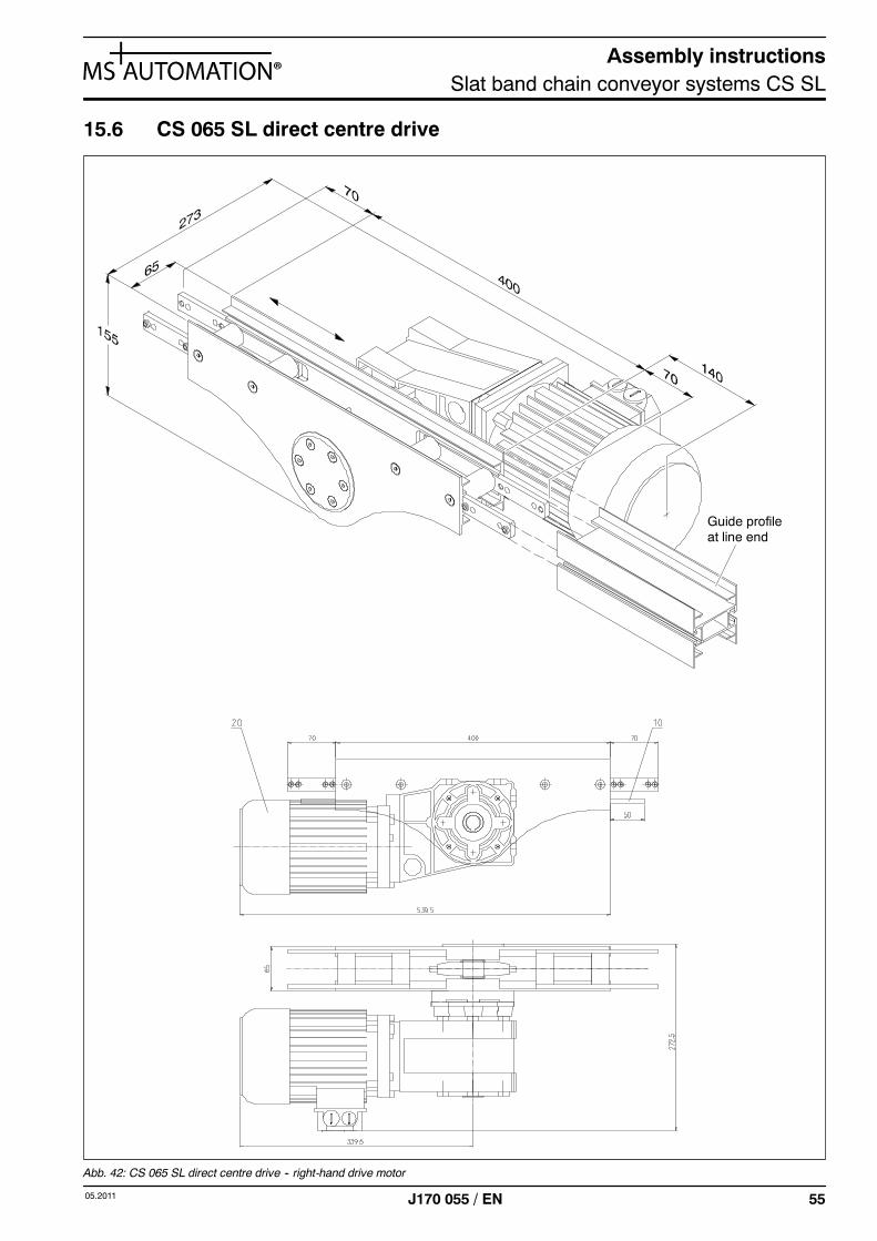
15.6 CS 065 SL direct centre drive
Guide profileat line end
Abb. 42: CS 065 SL direct centre drive -- right-hand drive motor
Assembly instructionsSlat band chain conveyor systems CS SL
56 05.2011J170 055 / EN
15.6.1 Parts list for CS 065 SL direct centre drive
Item no. Designation Prod. no. Quantity
CS 065 SL direct centre drive -- version:without drive motorwith drive motor
J927795.00.99J927796.00.99
10 Sliding strip section CS SL J927789.00.01 220 Bevel gear motor 1
Assembly instructionsSlat band chain conveyor systems CS SL
5705.2011 J170 055 / EN
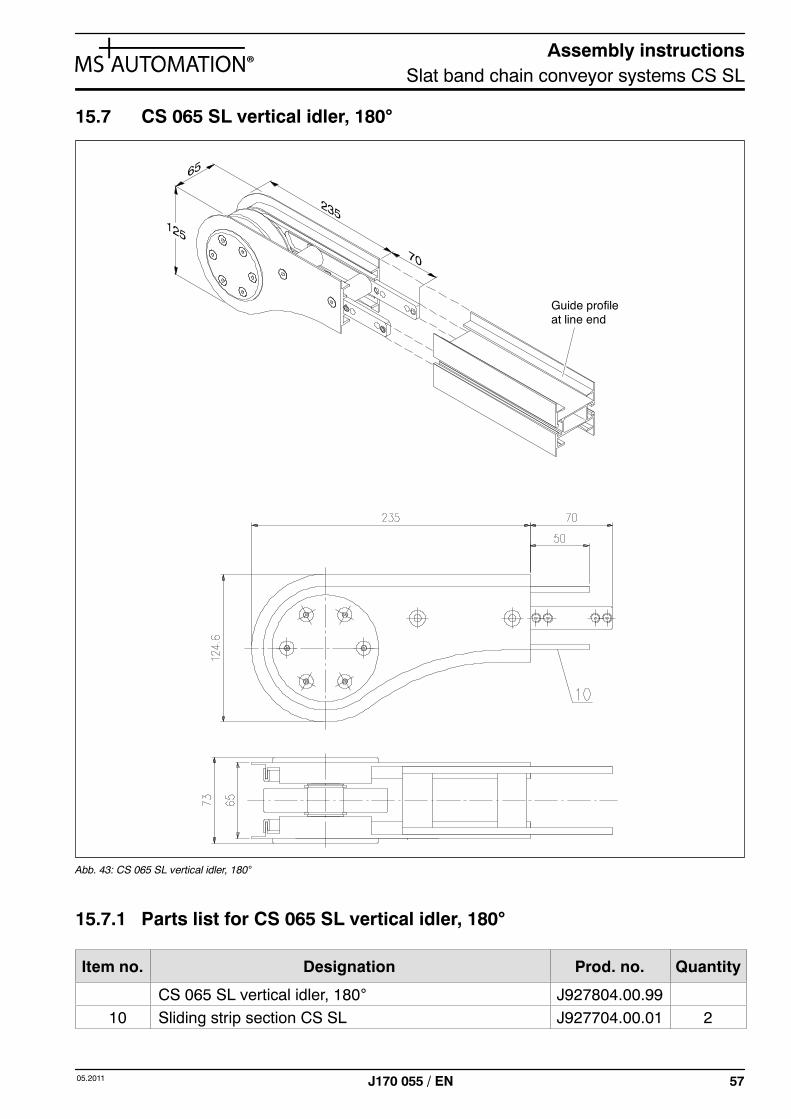
15.7 CS 065 SL vertical idler, 180°
Guide profileat line end
Abb. 43: CS 065 SL vertical idler, 180°
15.7.1 Parts list for CS 065 SL vertical idler, 180°
Item no. Designation Prod. no. Quantity
CS 065 SL vertical idler, 180° J927804.00.9910 Sliding strip section CS SL J927704.00.01 2
Assembly instructionsSlat band chain conveyor systems CS SL
58 05.2011J170 055 / EN
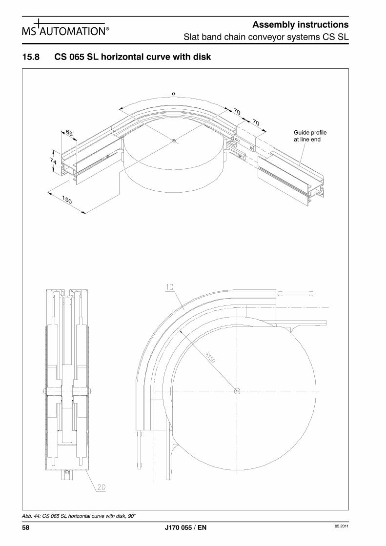
15.8 CS 065 SL horizontal curve with disk
α
Guide profileat line end
Abb. 44: CS 065 SL horizontal curve with disk, 90°
Assembly instructionsSlat band chain conveyor systems CS SL
5905.2011 J170 055 / EN
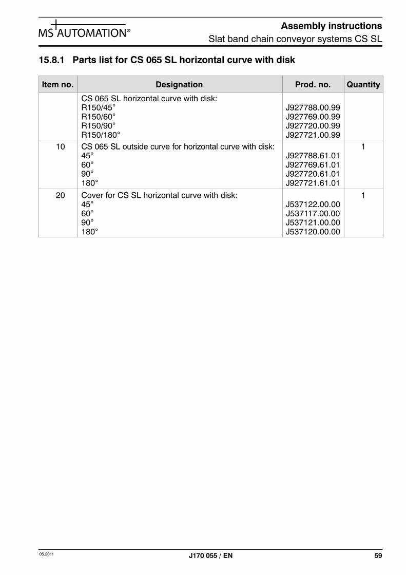
15.8.1 Parts list for CS 065 SL horizontal curve with disk
Item no. Designation Prod. no. Quantity
CS 065 SL horizontal curve with disk:R150/45°R150/60°R150/90°R150/180°
J927788.00.99J927769.00.99J927720.00.99J927721.00.99
10 CS 065 SL outside curve for horizontal curve with disk:45°60°90°180°
J927788.61.01J927769.61.01J927720.61.01J927721.61.01
1
20 Cover for CS SL horizontal curve with disk:45°60°90°180°
J537122.00.00J537117.00.00J537121.00.00J537120.00.00
1
Assembly instructionsSlat band chain conveyor systems CS SL
60 05.2011J170 055 / EN
16 CS 090 SL
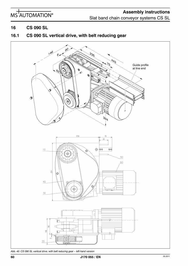
16.1 CS 090 SL vertical drive, with belt reducing gear
Guide profileat line end
Abb. 45: CS 090 SL vertical drive, with belt reducing gear -- left-hand version
Assembly instructionsSlat band chain conveyor systems CS SL
6105.2011 J170 055 / EN
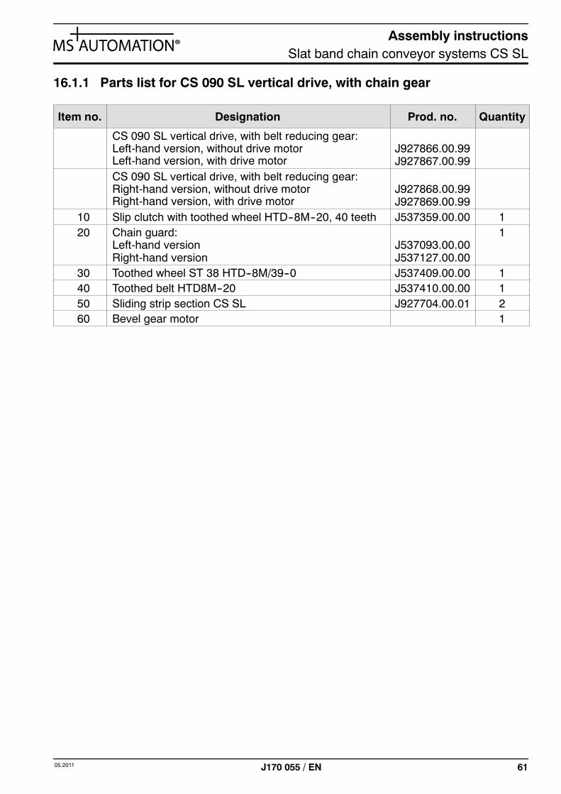
16.1.1 Parts list for CS 090 SL vertical drive, with chain gear
Item no. Designation Prod. no. Quantity
CS 090 SL vertical drive, with belt reducing gear:Left-hand version, without drive motorLeft-hand version, with drive motor
J927866.00.99J927867.00.99
CS 090 SL vertical drive, with belt reducing gear:Right-hand version, without drive motorRight-hand version, with drive motor
J927868.00.99J927869.00.99
10 Slip clutch with toothed wheel HTD--8M--20, 40 teeth J537359.00.00 120 Chain guard:
Left-hand versionRight-hand version
J537093.00.00J537127.00.00
1
30 Toothed wheel ST 38 HTD--8M/39--0 J537409.00.00 140 Toothed belt HTD8M--20 J537410.00.00 150 Sliding strip section CS SL J927704.00.01 260 Bevel gear motor 1
Assembly instructionsSlat band chain conveyor systems CS SL
62 05.2011J170 055 / EN
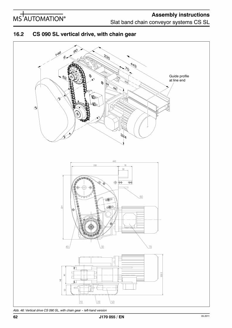
16.2 CS 090 SL vertical drive, with chain gear
Guide profileat line end
Abb. 46: Vertical drive CS 090 SL, with chain gear -- left-hand version
Assembly instructionsSlat band chain conveyor systems CS SL
6305.2011 J170 055 / EN
16.2.1 Parts list for CS 090 SL vertical drive, with chain gear
Item no. Designation Prod. no. Quantity
CS 090 SL vertical drive, with chain gear,left-hand version, up to 60 m/min:without drive motorwith drive motor
(1)
J927736.00.99J927737.01.99
toJ927737.09.99
CS 090 SL vertical drive, with chain gear,right-hand version, up to 60 m/min:without drive motorwith drive motor
(1)
J927738.00.99J927739.01.99
toJ927739.09.99
CS 090 SL vertical drive, with chain gear,left-hand version, up to 80 m/min:without drive motorwith drive motor
(2)
J927736.10.99J927737.10.99
CS 090 SL vertical drive, with chain gear,right-hand version, up to 80 m/min:without drive motorwith drive motor
(2)
J927738.10.99J927739.10.99
10 Slip clutch with sprocket 08--B1, 24 teeth J535035.00.00 120 Chain guard:
Left-hand versionRight-hand version
J537093.00.00J537127.00.00
1
30 Chain sprocket with hub on one side, 1/2”x5/16”, 22teeth
J537770.00.00 1
40 (1) Standard roller chain 08--B1,55 links including connecting link
(2) Marathon roller chain 08--B1,55 links including connecting link
J537095.00.00
J537502.00.00
1
50 Tensioning box, size 0, light--duty J537753.00.00 160 Sliding strip section CS SL J927704.00.01 270 Bevel gear motor 1
Assembly instructionsSlat band chain conveyor systems CS SL
64 05.2011J170 055 / EN
16.3 CS 090 SL direct drive
Guide profileat line end
Abb. 47: CS 090 SL direct drive -- right-hand version
Assembly instructionsSlat band chain conveyor systems CS SL
6505.2011 J170 055 / EN
16.3.1 Parts list for CS 090 SL direct drive
Item no. Designation Prod. no. Quantity
CS 090 SL direct drive -- left-hand version:without drive motorwith drive motor
J927740.00.99J927742.00.99
CS 090 SL direct drive -- right-hand version:without drive motorwith drive motor
J927743.00.99J927744.00.99
10 Sliding strip section CS SL J927704.00.01 220 Bevel gear motor 1
Assembly instructionsSlat band chain conveyor systems CS SL
66 05.2011J170 055 / EN
16.4 CS 090 SL centre drive, with belt reducing gear
Guide profileat line end
Abb. 48: CS 090 SL centre drive, with belt reducing gear -- left-hand version
Assembly instructionsSlat band chain conveyor systems CS SL
6705.2011 J170 055 / EN
16.4.1 Parts list for CS 090 SL centre drive, with belt reducing gear
Item no. Designation Prod. no. Quantity
CS 090 SL centre drive, with belt reducing gear:Left-hand version, without drive motorLeft-hand version, with drive motor
J927870.00.99J927871.00.99
CS 090 SL centre drive, with belt reducing gear:Right-hand version, without drive motorRight-hand version, with drive motor
J927872.00.99J927873.00.99
10 Slip clutch with toothed wheel HTD--8M--20, 40 teeth J537360.00.00 120 Chain guard:
Left-hand versionRight-hand version
J537093.00.00J537127.00.00
1
30 Toothed wheel ST 38 HTD--8M/39--0 J537409.00.00 140 Toothed belt HTD8M--20 J537410.00.00 150 Sliding strip section CS SL J927789.00.01 260 Bevel gear motor 1
Assembly instructionsSlat band chain conveyor systems CS SL
68 05.2011J170 055 / EN
16.5 CS 090 SL centre drive, with chain gear
Guide profileat line end
Abb. 49: CS 090 SL centre drive, with chain gear -- left-hand version
Assembly instructionsSlat band chain conveyor systems CS SL
6905.2011 J170 055 / EN
16.5.1 Parts list for CS 090 SL centre drive, with chain gear
Item no. Designation Prod. no. Quantity
CS 090 SL centre drive, with chain gear:Left-hand version, without drive motorLeft-hand version, with drive motor
J927813.00.99J927815.00.99
CS 090 SL centre drive, with chain gear:Right-hand version, without drive motorRight-hand version, with drive motor
J927816.00.99J927817.00.99
10 Slip clutch with sprocket 08--B1, 24 teeth J535046.00.00 120 Chain guard:
Left-hand versionRight-hand version
J537093.00.00J537127.00.00
1
30 Chain sprocket with hub on one side, 1/2”x5/16”,22 teeth
J537770.00.00 1
40 Roller chain 08--B1, 55 links including connecting link J537095.00.00 150 Tensioning box, size 0, light--duty J537753.00.00 160 Sliding strip section CS SL J927789.00.01 270 Bevel gear motor 1
Assembly instructionsSlat band chain conveyor systems CS SL
70 05.2011J170 055 / EN
16.6 CS 090 SL direct centre drive
Guide profileat line end
Abb. 50: CS 090 SL direct centre drive -- right-hand drive motor
Assembly instructionsSlat band chain conveyor systems CS SL
7105.2011 J170 055 / EN
16.6.1 Parts list for CS 090 SL direct centre drive
Item no. Designation Prod. no. Quantity
CS 090 SL direct centre drive -- version:without drive motorwith drive motor
J927819.00.99J927820.00.99
10 Sliding strip section CS SL J927789.00.01 220 Bevel gear motor 1
Assembly instructionsSlat band chain conveyor systems CS SL
72 05.2011J170 055 / EN
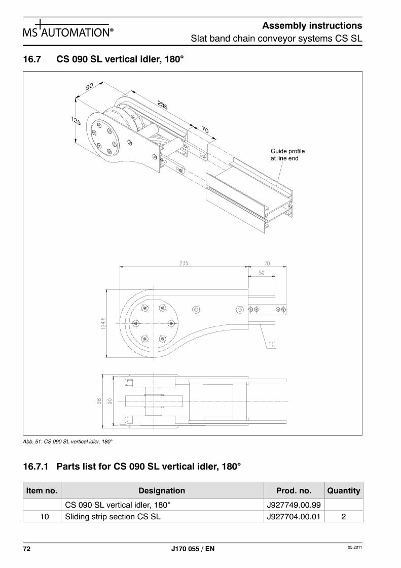
16.7 CS 090 SL vertical idler, 180°
Guide profileat line end
Abb. 51: CS 090 SL vertical idler, 180°
16.7.1 Parts list for CS 090 SL vertical idler, 180°
Item no. Designation Prod. no. Quantity
CS 090 SL vertical idler, 180° J927749.00.9910 Sliding strip section CS SL J927704.00.01 2
Assembly instructionsSlat band chain conveyor systems CS SL
7305.2011 J170 055 / EN
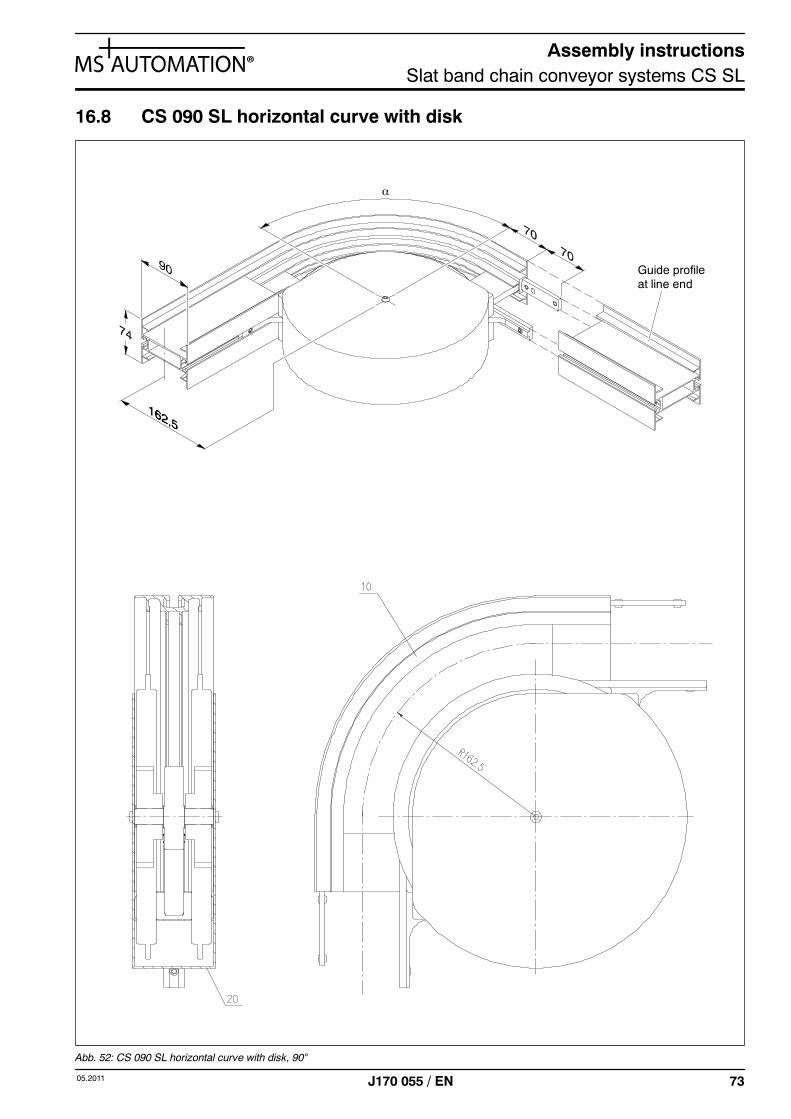
16.8 CS 090 SL horizontal curve with disk
α
Guide profileat line end
Abb. 52: CS 090 SL horizontal curve with disk, 90°
Assembly instructionsSlat band chain conveyor systems CS SL
74 05.2011J170 055 / EN
16.8.1 Parts list for CS 090 SL horizontal curve with disk
Item no. Designation Prod. no. Quantity
CS 090 SL horizontal curve with disk:R162.5/45°R162.5/60°R162.5/90°R162.5/180°
J927770.00.99J927771.00.99J927751.00.99J927752.00.99
10 CS 090 SL outside curve for horizontal curve with disk:45°60°90°180°
J927770.61.01J927771.61.01J927751.61.01J927752.61.01
1
20 Cover for CS SL horizontal curve with disk:45°60°90°180°
J537122.00.00J537117.00.00J537121.00.00J537120.00.00
1
Assembly instructionsSlat band chain conveyor systems CS SL
7505.2011 J170 055 / EN
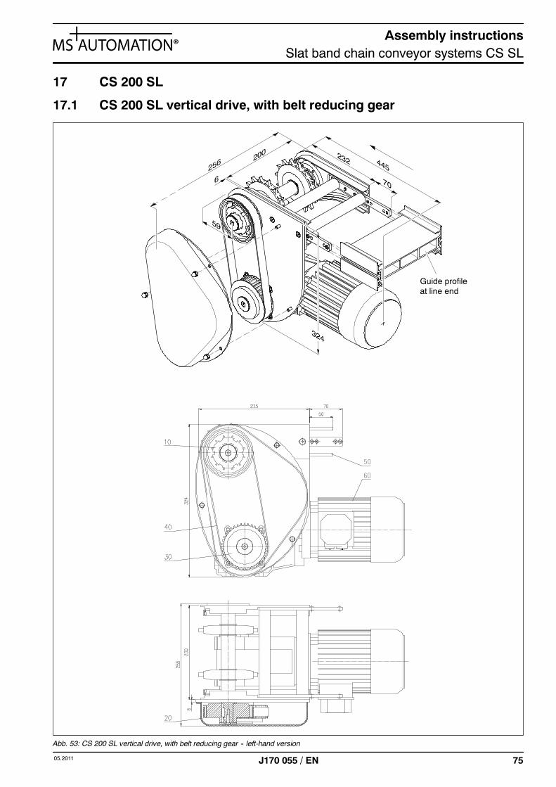
17 CS 200 SL
17.1 CS 200 SL vertical drive, with belt reducing gear
Guide profileat line end
Abb. 53: CS 200 SL vertical drive, with belt reducing gear -- left-hand version
Assembly instructionsSlat band chain conveyor systems CS SL
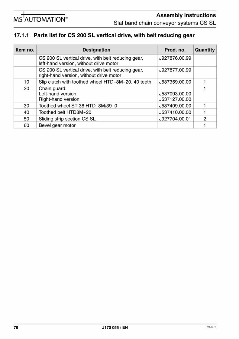
76 05.2011J170 055 / EN
17.1.1 Parts list for CS 200 SL vertical drive, with belt reducing gear
Item no. Designation Prod. no. Quantity
CS 200 SL vertical drive, with belt reducing gear,left-hand version, without drive motor
J927876.00.99
CS 200 SL vertical drive, with belt reducing gear,right-hand version, without drive motor
J927877.00.99
10 Slip clutch with toothed wheel HTD--8M--20, 40 teeth J537359.00.00 120 Chain guard:
Left-hand versionRight-hand version
J537093.00.00J537127.00.00
1
30 Toothed wheel ST 38 HTD--8M/39--0 J537409.00.00 140 Toothed belt HTD8M--20 J537410.00.00 150 Sliding strip section CS SL J927704.00.01 260 Bevel gear motor 1
Assembly instructionsSlat band chain conveyor systems CS SL
7705.2011 J170 055 / EN
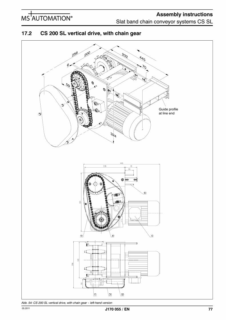
17.2 CS 200 SL vertical drive, with chain gear
Guide profileat line end
Abb. 54: CS 200 SL vertical drive, with chain gear -- left-hand version
Assembly instructionsSlat band chain conveyor systems CS SL
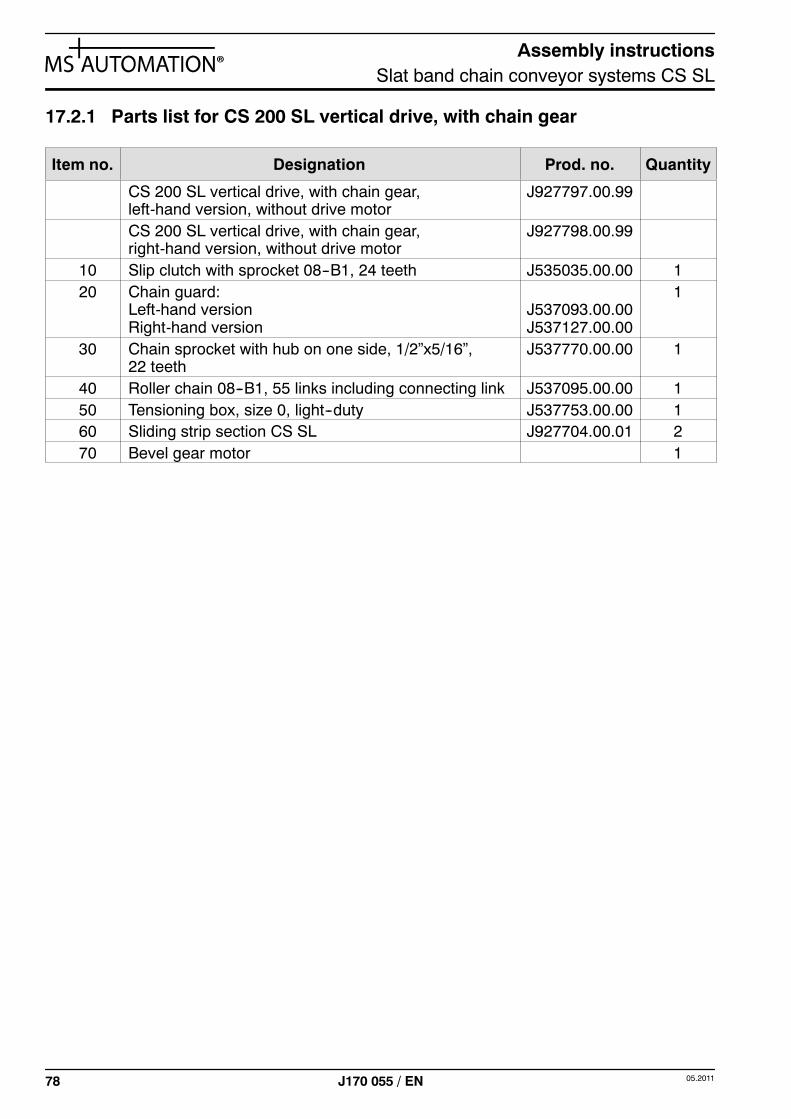
78 05.2011J170 055 / EN
17.2.1 Parts list for CS 200 SL vertical drive, with chain gear
Item no. Designation Prod. no. Quantity
CS 200 SL vertical drive, with chain gear,left-hand version, without drive motor
J927797.00.99
CS 200 SL vertical drive, with chain gear,right-hand version, without drive motor
J927798.00.99
10 Slip clutch with sprocket 08--B1, 24 teeth J535035.00.00 120 Chain guard:
Left-hand versionRight-hand version
J537093.00.00J537127.00.00
1
30 Chain sprocket with hub on one side, 1/2”x5/16”,22 teeth
J537770.00.00 1
40 Roller chain 08--B1, 55 links including connecting link J537095.00.00 150 Tensioning box, size 0, light--duty J537753.00.00 160 Sliding strip section CS SL J927704.00.01 270 Bevel gear motor 1
Assembly instructionsSlat band chain conveyor systems CS SL
7905.2011 J170 055 / EN
17.3 CS 200 SL direct drive
Guide profileat line end
Abb. 55: CS 200 SL direct drive -- right-hand version
Assembly instructionsSlat band chain conveyor systems CS SL
80 05.2011J170 055 / EN
17.3.1 Parts list for CS 200 SL direct drive
Item no. Designation Prod. no. Quantity
CS 200 SL direct drive -- left-hand version,without drive motor
J927799.00.99
CS 200 SL direct drive -- right-hand version,without drive motor
J927801.00.99
10 Sliding strip section CS SL J927704.00.01 220 Bevel gear motor 1
Assembly instructionsSlat band chain conveyor systems CS SL
8105.2011 J170 055 / EN
17.4 CS 200 SL vertical idler, 180°
Guide profileat line end
Abb. 56: CS 200 SL vertical idler, 180°
17.4.1 Parts list for CS 200 SL vertical idler, 180°
Pos.-Nr. Bezeichnung Art.-Nr. Anzahl
CS 200 SL vertical idler, 180° J927827.00.9910 Sliding strip section CS SL J927704.00.01 2
Assembly instructionsSlat band chain conveyor systems CS SL
82 05.2011J170 055 / EN


MS Plus AutomationHöfeweg 62a, 33619 BielefeldTel.: +49 521 304 30-0 Fax: +49 521 304 [email protected] www.msplusautomation.com
Artic
le n
o. J
170
055
Tran
slat
ion
- Tec
hnic
al c
hang
es r
eser
ved
- TI C
S SL
-e -
04/2
011
- 200
10379_Monatgeanleitung SBKFS_CSSL_DINA5_e_110504.indd 2 04.05.2011 15:36:47 Uhr