Embed Size (px)
Citation preview

STA0003
CPS TO POT LIMIT SWITCH
CONVERSION
F2459540(CPS)
F2549296(POT)
ASSEMBLY MANUAL
1
CONTENTS TOOLS REQUIRED .............................................................................................................................................. 2
PARTS LIST ........................................................................................................................................................... 3
INSTRUCTIONS .................................................................................................................................................... 4
0. Limit Switch Identification .......................................................................................................................... 4
1. Removing the CPS Limit Switch ................................................................................................................. 4
2. Installing the POT Limit Switch .................................................................................................................. 8
2
TOOLS REQUIRED (1) Flathead Screw Driver (small)
(1) Philips Head Screw Driver
NOTE: Some screws may need a larger Philips Head to grip properly,
so a second, thicker screwdriver may be necessary.

3
PARTS LIST
Item # Description Qty.
ITEMS USED IN CONVERSION
F2459296 LIMIT.SW.S. LM.125/250+POTM. 1
F34331018-06 LM.125 200-240V 60HZ 1~PH +CPS 1 (IF CONVERGING 125)
F34331024-06 LM.250 200-230V 60HZ 1~PH + CPS 1 (IF CONVERTING 250)
AFTER CONVERSION, ITEMS BECOME:
F34331005-06 LM.125 200-240V 60HZ 1~PH+POT 1 (IF CONVERTING 125)
F34331010-06 LM.250 200-240V 60HZ 1~PH +POT 1 (IF CONVERTING 250)
LEFTOVER ITEMS (TAKEN OUT OF ACT.):
F2459540 LIMIT SW.SET iM-LM.125/250+CPS 1

4
INSTRUCTIONS 0. Limit Switch Identification
Before beginning the CPS to POT
Limit Switch exchange, it is
important to confirm the motor’s
limit switch is CPS and a POT
switch is being put in its place. The
POT version, F2459296, shown on
the left, has a flathead screw shown
in the location with the arrow,
while the CPS version, F2459540,
on the right has a Philips head
screw. The center gears on the POT
is black, while the CPS ones are
white.
1. Removing the CPS Limit
Switch a. Remove the black cover on the
F34331018-06 (125) or
F34331024-06 (250) actuator
with a Philips head
screwdriver.

5
b. Inside this cover is a plastic bag
of parts. Remove it for now, it
will be replaced when the
conversion is finished.
c. Inside the cover you’ll see two
white wire junction boxes.
Using a Philips screwdriver,
remove the two front-facing
mounting screws that hold the
smaller junction box to the
switch assembly. This will also
remove the plastic guard sheet
attached to it. Set the sheet and
screws aside for now.
d. There are two black wires
running into the larger junction
box that must be unfastened
and removed from the box
using a Philips head
screwdriver as shown.
IMPORTANT:
Keep track of the wires and
their positions in this step and
the next step, as they will need
to be reinstalled later.

6
e. Additionally, on the same box
are two more wires near the
bottom (black and
green/yellow) that must be
removed.
f. There is a screw and washer
behind the junction box that
fastens the Limit Switch
assembly to the actuator.
Remove these using a Philips
head screwdriver.
7
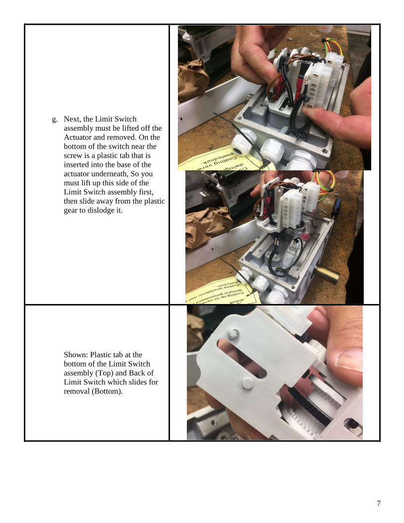
g. Next, the Limit Switch
assembly must be lifted off the
Actuator and removed. On the
bottom of the switch near the
screw is a plastic tab that is
inserted into the base of the
actuator underneath, So you
must lift up this side of the
Limit Switch assembly first,
then slide away from the plastic
gear to dislodge it.
Shown: Plastic tab at the
bottom of the Limit Switch
assembly (Top) and Back of
Limit Switch which slides for
removal (Bottom).

8
2. Installing the POT Limit
Switch a. In the same manner that the
CPS switch assembly was
removed from the actuator,
slide in and snap in the new
POT assembly in its place. The
black plastic gear may need to
be turned slightly to fit into the
worm gear, which could
prevent it from fully seating.
IMPORTANT!
Make sure the limit switch tab
on the bottom snaps into the
actuator!
9
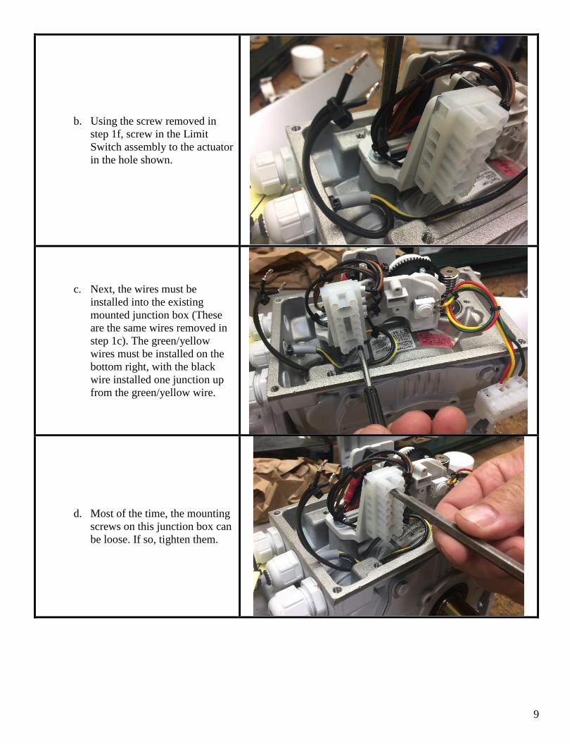
b. Using the screw removed in
step 1f, screw in the Limit
Switch assembly to the actuator
in the hole shown.
c. Next, the wires must be
installed into the existing
mounted junction box (These
are the same wires removed in
step 1c). The green/yellow
wires must be installed on the
bottom right, with the black
wire installed one junction up
from the green/yellow wire.
d. Most of the time, the mounting
screws on this junction box can
be loose. If so, tighten them.
10
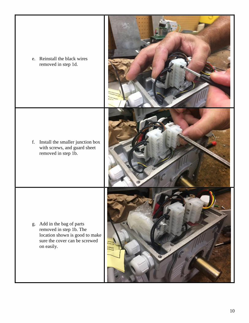
e. Reinstall the black wires
removed in step 1d.
f. Install the smaller junction box
with screws, and guard sheet
removed in step 1b.
g. Add in the bag of parts
removed in step 1b. The
location shown is good to make
sure the cover can be screwed
on easily.

11
h. Reinstall the cover with a
Philips head screwdriver. After
this conversion there will be a
cps limit switch left over. This
will have to be checked back
into inventory, along with the
CPS actuator number.

12
IF THERE IS ANY MISSING,
INACCURATE, OR INCOMPLETE
INFORMATION CONTAINED IN THIS
ASSEMBLY MANUAL, PLEASE EMAIL
[email protected] WITH
CORRECTIONS.