Embed Size (px)
Citation preview

Prepared for:
Falcon Panel Products Ltd.
Clock House
Station Approach
Shepperton
Middlesex
TW17 8AN
Assessment Report CONFIDENTIAL
Report: Chilt/A02066 Revision K
Global Fire Resistance Assessment of:
Strebord 35+
Strebord 38+
Strebord 44
Strebord Superpan for: 30 Minutes Fire Resistance
Valid From: 02 September 2013
Valid Until: 02 September 2018
This document is confidential and remains the property of Chiltern International Fire Ltd. The legal validity of this report can only be claimed on the presentation of the complete
report.
Page 1 of 86

BM TRADA – the new name for Chiltern International Fire Ltd
From July 1st 2013, Chiltern International Fire Ltd commenced trading under the name of its parent company BM TRADA and at the same time adopted a brand new visual identity. Historically, the group has delivered its services through a number of individual companies: BM TRADA Certification Ltd, TRADA Technology Ltd, Chiltern International Fire Ltd (including Chiltern Dynamics) and a network of international offices. Both BM TRADA Group and these individual companies will now trade under the same name - BM TRADA - and adopt the new visual identity. To coincide with this change, our Technical Reports, Test Reports, Products Assessments, company stationery and marketing collateral have been re-designed to carry the new branding and visual identity. The validity of all documents previously issued by the individual companies including certificates, test reports and product assessments is unaffected by this change and a letter to this effect will be available to download from our website www.bmtradagroup.com. About BM TRADA. With origins dating back to 1934, we have a deep history and services which are highly valued by our customers. We offer independent certification, testing, inspection, training and technical services around the world. In all these areas we continue to use industry-leading experts in their chosen fields to develop and deliver services – an ethos that has been at the heart of our approach since we began. A recent review of our businesses and customers revealed that the individual identities sometimes make communications confusing, and that in an already complex business area, clarity and simplicity in communications is rare, but valued. It also revealed that a single identity and combined offer would help us strengthen our appeal. With this in mind, we brought the companies together under the name BM TRADA and took the opportunity to create a fresh new visual identity. We have modernised our image and combined our strengths. However, our values, our people and the integrity of our services remain the same. I hope you will welcome these changes and the improvements they will bring. Jon Osborn Chief Operating Officer

The legal validity of this report can only be claimed on presentation of the complete report.
Report for: Falcon Panel Products Ltd. Page 3 of 86
Ref: Chilt/A02066 Revision K
Contents
Page No.
1 Introduction................................................................................................................... 4
2 General Description of Construction ............................................................................. 4
3 Leaf Sizes .................................................................................................................... 5
4 Configurations .............................................................................................................. 5
5 Leaf Size Adjustment .................................................................................................... 5
6 Glazing ......................................................................................................................... 6
7 Overpanels ................................................................................................................... 14
8 Fanlights and Sidescreens ........................................................................................... 15
9 Door Frames ................................................................................................................ 21
10 Facings ......................................................................................................................... 24
11 Intumescent Materials .................................................................................................. 26
12 Lippings ........................................................................................................................ 27
13 Adhesives ..................................................................................................................... 29
14 Tested Hardware .......................................................................................................... 30
15 Additional & Alternative Hardware ................................................................................ 30
16 Door Gaps .................................................................................................................... 35
17 Structural Opening ........................................................................................................ 35
18 Fixings .......................................................................................................................... 35
19 Sealing to Structural Opening ....................................................................................... 35
20 Insulation ...................................................................................................................... 37
21 Smoke Control .............................................................................................................. 37
22 Conclusion ................................................................................................................... 38
23 Declaration by the Applicant ......................................................................................... 39
24 Limitations .................................................................................................................... 40
25 Validity .......................................................................................................................... 40
Appendix A1 - Nordform Steel Frame Doorsets ................................................................... 41
Appendix A2 - Strebord 54 Steel Frame Doorsets .............................................................. 44
Appendix B - Performance Data .......................................................................................... 46
Appendix C - Revisions and Amendments........................................................................... 50
Appendix D - Glazing Systems ............................................................................................ 51
Appendix E - Data Sheets ................................................................................................... 55
The legal validity of this report can only be claimed on presentation of the complete report.
Report for: Falcon Panel Products Ltd. Page 4 of 86
Ref: Chilt/A02066 Revision K
1 Introduction
This document constitutes a fire resistance assessment relating to Strebord 35+,
Strebord 38+, Strebord 44 and Strebord Superpan, 30 minute fire resisting doorsets, for Falcon Panel Products Ltd. The assessment uses established extrapolation and interpretation techniques in order to extend the scope of application by determining the limits for the designs, based on the tested constructions and performances obtained. The assessment is an evaluation of the potential fire resistance performance, if the elements were to be tested in accordance with BS 476: Part 22: 1987.
2 General Description of Construction
2.1 Strebord 35+
The primary construction for door leaves of this design comprises the following:
• A core of 35mm thick Strebord particleboard (minimum density 560kg/m3) with 4mm thick MDF facings to both faces of the leaf. Where required, the leaves are to be lipped with hardwood. The faces are to be bonded by the doorset manufacturer in accordance with this assessment.
Notes:
1) It is permissible for the doorset manufacturer to fit 35mm thick by 40mm wide softwood (min. density 430kg/m³) stiles and rails to the perimeter of the door core. Stiles and rails must be spot bonded with PVA before bonding the faces. If using stiles and rails, leaf size limitations will apply (see relevant data sheets contained in Appendix E). The stiles and rails may be reduced by a maximum of 3mm in width for final sizing and squaring before lipping
2) The applied facings for this design may butt up to or conceal the lipping and must be adhered by fully bonding using a PVA adhesive (see section 13).
2.2 Strebord 38+
The primary construction for door leaves of this design comprises the following:
• A homogenous solid sheet of 38mm thick Strebord particleboard (minimum density 590kg/m3) with 4mm thick chipboard facings. Where required, the leaves are to be lipped with hardwood. The faces are to be bonded by the doorset manufacturer in accordance with this assessment.
Notes:
1) It is permissible to fit 38mm thick by 40mm wide softwood (min. density 430kg/m³) stiles and rails to the perimeter of the door core. Stiles and rails must be spot bonded with PVA before bonding the faces. If using stiles and rails, leaf size limitations will apply (see relevant data sheets contained in Appendix E). The stiles and rails may be reduced by a maximum of 3mm in width for final sizing and squaring before lipping
2) The applied facings for this design may butt up to or conceal the lipping and must be adhered by fully bonding using a PVA adhesive (see section 13).
2.3 Strebord 44
The primary construction for door leaves of this design comprises the following:
• A homogenous solid sheet of 44mm thick Strebord 44 particleboard (minimum density 530kg/m3 to maximum density 630kg/m3). Where required, the leaves are to be lipped with hardwood.

The legal validity of this report can only be claimed on presentation of the complete report.
Report for: Falcon Panel Products Ltd. Page 5 of 86
Ref: Chilt/A02066 Revision K
2.4 Strebord Superpan
The primary construction for door leaves of this design comprises the following:
• A homogenous solid sheet of 44mm thick Strebord particleboard (minimum density 560kg/m3) with 3mm thick integral outer MDF facings, fully bonded with a PVA adhesive, incorporated during the manufacturing process (factory applied). Where required, the leaves are to be lipped with hardwood.
It is the opinion of BM TRADA that based on the test evidence listed in Appendix B, the construction options available for each door leaf design can be applied to any of the door leaf designs listed in sections 2.1 - 2.4, unless otherwise specifically stated herein.
3 Leaf Sizes
The approval for increased leaf dimensions is based on the tests listed in Appendix B and takes into account the margin of over performance above 30 minutes integrity for the design and the characteristics exhibited during test. Data sheets specifying the maximum approved leaf sizes and graphs showing the permitted gradient between maximum height and width are contained in Appendix E.
Doorsets with reduced dimensions are deemed to be less onerous. Therefore, doors with dimensions that are less than those tested and stated in Appendix E may be manufactured.
4 Configurations
Based on the test evidence listed in Appendix B, this assessment covers the following doorset configurations:
Abbreviation Description
LSASD & ULSASD Latched & unlatched, single acting, single doorset
DASD Double acting, single doorset
LSASD+OP & ULSASD+OP Latched & unlatched, single acting, single doorset with overpanel
DASD+OP Double acting, single doorset with overpanel
LSADD & ULSADD Latched & unlatched, single acting, double doorset
DADD Double acting, double doorset
LSADD+OP & ULSADD+OP Latched & unlatched, single acting, double doorset with overpanel
DADD+OP Double acting, double doorset with overpanel
Unequal leaf double doorsets are covered by this assessment with no restriction on the smaller leaf dimension.
5 Leaf Size Adjustment
The Falcon Panel Products Ltd. door leaf designs referred to in sections 2.1 - 2.4 of this assessment may be altered as follows:
Element Reduction
Leaf
No stiles & rails The manufactured size of the leaf may be reduced in height or width without restriction
Stiles & rails (sections 2.1 & 2.2)
The manufactured dimensions of Strebord 35+ and 38+ fitted with stiles and rails cannot be reduced post manufacture i.e. factory finished door
Lipping The dimensions stated in section 12 may be reduced by 20% for fitting purposes

The legal validity of this report can only be claimed on presentation of the complete report.
Report for: Falcon Panel Products Ltd. Page 6 of 86
Ref: Chilt/A02066 Revision K
6 Glazing
The testing conducted on the door leaf designs referred to in sections 2.1 - 2.4 of this assessment have demonstrated that the designs are capable of tolerating relatively large glazed apertures, whilst providing a margin of over performance. Glazing is therefore acceptable within the following parameters:
The maximum assessed glazed area for all configurations is 1.9m². The glazing system must be one of the following tested proprietary systems:
6.1 Assessed Glazing Systems
Glazing System Manufacturer Max. Area (m2)
1. Fireglaze 30 Sealmaster Ltd. 1.9
2. Therm-A-Strip 30 Intumescent Seals Ltd. 1.9
3. Firestrip 30 Hodgsons Sealants Ltd. 1.9
4. Pyroglaze 30 Mann McGowan Ltd. 1.33
5. Norsound Vision 30 (see section 6.7 for additional scope)
Norsound Ltd. 1.33
6. Norsound Universal 30 (see section 6.8 for additional scope)
Norsound Ltd. 1.33
7. System 36/6 Lorient Polyproducts Ltd. 1.33
8. System 36/6 Plus Lorient Polyproducts Ltd. 1.33
9. Flexible Figure 1 Lorient Polyproducts Ltd. 1.33
10. R8193 Pyroplex Ltd. 1.33
11. 30049 Pyroplex Ltd. 1.33
12. 30054 Pyroplex Ltd. 0.72
6.2 Assessed Glass Products
Assessed glass types are as follows:
Glass Type Manufacturer Thickness
(mm) Max. Area (m²)
1 Pyroshield Pilkington Group Ltd. 6 & 7 1.9
2 Pyroshield 2 Pilkington Group Ltd. 6 & 7 1.9
3 Pyran S Schott UK Ltd. 6 1.9
4 Pyrostem CGI Ltd. 6 1.25
5 Pyroswiss¹ Vetrotech Saint Gobain 6 0.8
6 ESG Pyrotech 630² Essex Safety Glass Ltd. 6 0.8
7 Pyrocet XPT³ C3S Ltd. 6 1.9
8 Pyroclear 30-0014 Pilkington Group Ltd. 6 1.2
9 Pyroguard EW 30 CGI Ltd. 7 1.14
10 Pyrobelite 7 AGC Flat Glass UK 7 1.9
11 Pyrodur 30-104 Pilkington Group Ltd. 7 1.9
12 Pyrodur 60-10 Pilkington Group Ltd. 10 1.9
13 Pyroguard EW MAXI CGI Ltd. 11 0.87
14 Pyranova 15-S2.0 Schott UK Ltd. 11 1.9
15 Pyrobelite 12 AGC Flat Glass UK 12 1.9
16 Pyrodur 60-20 Pilkington Group Ltd. 13 1.9
17 Pyroguard EI 30 CGI Ltd. 15 1.9
18 Pyrostop 30-10 Pilkington Group Ltd. 15 1.9
19 Pyrobel 16 AGC Flat Glass UK 16 1.9

The legal validity of this report can only be claimed on presentation of the complete report.
Report for: Falcon Panel Products Ltd. Page 7 of 86
Ref: Chilt/A02066 Revision K
Notes:
1. Pyroswiss product limited to 0.8m2 and glazing system 3 as defined in section 6.1.
2. ESG Pyrotech 630 glass is limited to 0.8m2 and may only be used with the tested glazing
system depicted in Appendix D.
3. C3S Pyrocet XPT may only be utilised with the tested glazing system as described in section 6.4 below.
4. Pilkington Pyroclear is limited to 1.2m² and may only be utilised with the tested glazing system as described in section 6.5 below.
5. Glass types 17-19 are fully insulating for 30 minutes in terms of the criteria set out in BS 476: Part 20: 1987.
6. All glass types must be fitted fully in accordance with the manufacturers' tested details/installation requirements, particularly with respect to edge cover and expansion clearance.
6.3 Glazing Beads & Installation
Glazing beads must be from hardwood as specified in the following table:
Material Profile Min. Density
(kg/m3)
Application
Hardwood Splayed 640 All proprietary systems detailed in 6.1 and Appendix D
Hardwood Splayed
and Flush 640
Proprietary systems 1 & 2 as specified in 6.1 and all glass types specified in 6.2 (see Appendix D for further details)
Hardwood Square 640 Proprietary systems 1, 2 & 3 as specified in 6.1 and glass types 9-19 as specified in 6.2
Glazing beads must be retained in position with 40mm long x 2mm diameter steel pins or 40mm long No. 6-8 screws, inserted at 35-40º to the vertical. Fixings must be at 150mm maximum centres and no more than 50mm from each corner. Pneumatically fired pins are acceptable providing the pins meet the specification given above.
See Appendix D for square and splayed bead profile options. A 6–10mm thick square aperture liner is permitted for use with square beads providing it is constructed from hardwood of minimum density 640kg/m3 and glued in position using a UF, PVA or PU type adhesive.
Glazed openings must not be less than 100mm from any door edge. Multiple apertures are acceptable within the permitted glazed area, with a minimum dimension of 80mm between apertures.
Aperture shape is not restricted, providing the glazing system and beads can effectively accommodate the required profile.
False timber beads may be bonded to the glass face with an intumescent mastic/silicon, or a 0.5-2mm thick self adhesive intumescent tape/strip. Suitable glass for this application is restricted to types 9-19.
Timber for glazing beads must be hardwood, straight grained, joinery quality, free from knots, splits and checks.

The legal validity of this report can only be claimed on presentation of the complete report.
Report for: Falcon Panel Products Ltd. Page 8 of 86
Ref: Chilt/A02066 Revision K
6.4 Pyrocet XPT Glazing System
The following system must be used with the Pyrocet XPT glass type listed in section 6.2:
1. Hardwood (min. density 640kg/m³) glazing beads 26mm high x 22mm wide with an 18º chamfer and a 5mm x 5mm bolection return.
2. Beads must be retained in position with 50mm long x 2mm diameter steel pins or 50mm long No. 6-8 screws, inserted at 35-40º to the vertical at no more than 50mm from each corner and at 150mm maximum centres. Pneumatically fired pins are acceptable providing the pins meet the specification given above.
3. 10mm x 2mm Ceramic fibre tape is to be used between the bead and face of the glass. The tape must finish flush with the top of the bead.
4. The glass must be fitted with maximum 8mm edge cover and allowing for 13mm expansion on all edges.
5. An 8mm thick hardwood aperture liner is to be fitted using PVA or PU adhesive.
6. Aperture shape is not restricted, providing the glazing system and beads are compatible with that shape.
7. Timber for glazing beads must be hardwood, straight grained, joinery quality, free from knots, splits and checks.
8. Glazed openings must not be less than 100mm from any edge, with a minimum dimension of 80mm between apertures.
9. Multiple apertures are permitted, subject to point 8 above.
6.5 Pilkington Pyroclear Glazing System
The following system must be used with the Pilkington Pyroclear glass type listed in section 6.2:
1. Hardwood (min. density 640kg/m³) glazing beads 25mm high x 22mm deep with a 22º chamfer and a 5mm x 5mm bolection return.
2. Beads must be retained in position with 50mm long x 2mm diameter steel pins or 50mm long No. 6-8 steel screws, inserted at 45º to the vertical, at no more than 50mm from each corner and at 150mm maximum centres. Pneumatically fired pins are acceptable providing the pins meet the specification given above.
3. 15mm x 5mm Fibrefrax ceramic tape is to be used between the bead and the glass on both faces. The tape must finish flush with the top of the bead.
4. 10mm x 2mm Dufaylite Interdens must be fitted lining the glazing aperture.
5. The glass must be fitted with maximum 10mm edge cover and allowing for 10mm expansion on all edges.
6. Aperture shape is not restricted, providing the glazing system and beads are compatible with that shape.
7. Timber for glazing beads must be hardwood, straight grained, joinery quality, free from knots, splits and checks.
8. Glazed openings must not be less than 100mm from any edge, with a minimum dimension of 80mm between apertures.
9. Multiple apertures are permitted, subject to point 8 above.
The legal validity of this report can only be claimed on presentation of the complete report.
Report for: Falcon Panel Products Ltd. Page 9 of 86
Ref: Chilt/A02066 Revision K
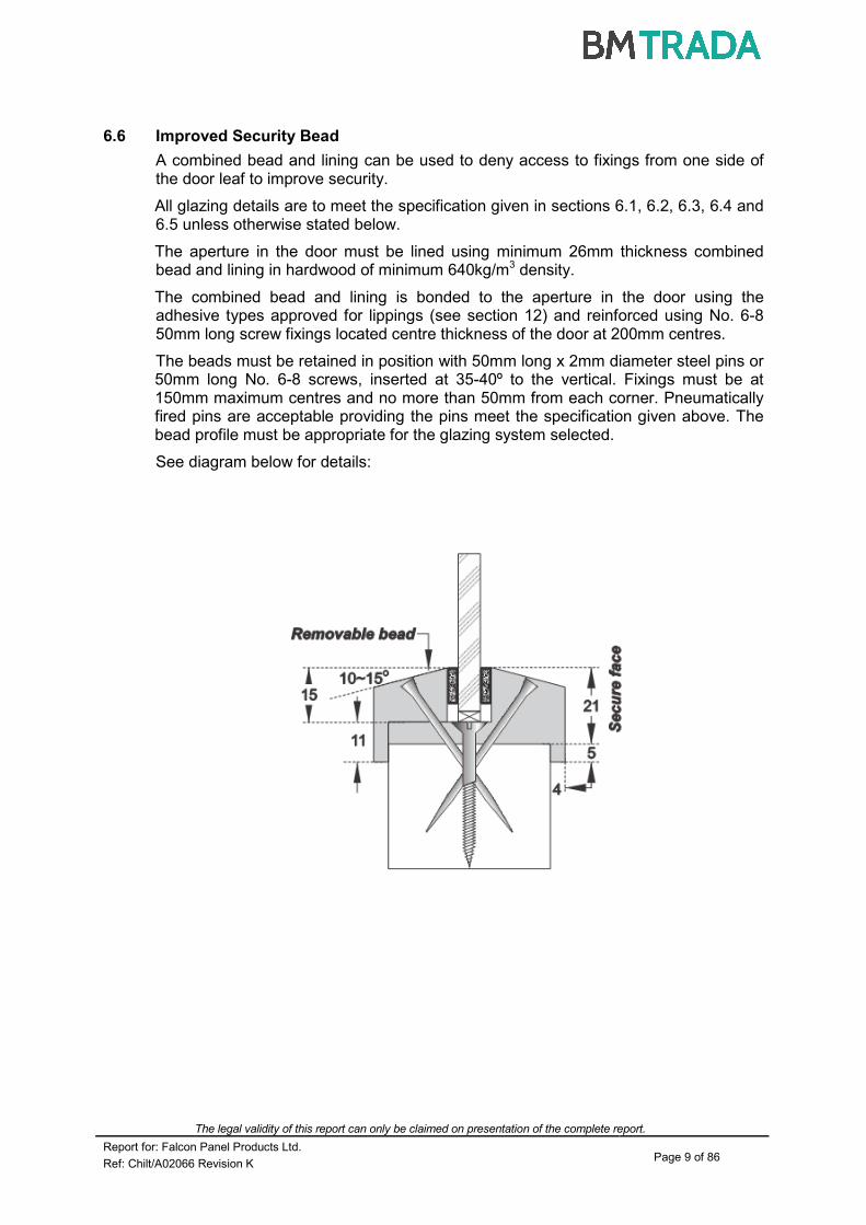
6.6 Improved Security Bead
A combined bead and lining can be used to deny access to fixings from one side of the door leaf to improve security.
All glazing details are to meet the specification given in sections 6.1, 6.2, 6.3, 6.4 and 6.5 unless otherwise stated below.
The aperture in the door must be lined using minimum 26mm thickness combined bead and lining in hardwood of minimum 640kg/m3 density.
The combined bead and lining is bonded to the aperture in the door using the adhesive types approved for lippings (see section 12) and reinforced using No. 6-8 50mm long screw fixings located centre thickness of the door at 200mm centres.
The beads must be retained in position with 50mm long x 2mm diameter steel pins or 50mm long No. 6-8 screws, inserted at 35-40º to the vertical. Fixings must be at 150mm maximum centres and no more than 50mm from each corner. Pneumatically fired pins are acceptable providing the pins meet the specification given above. The bead profile must be appropriate for the glazing system selected.
See diagram below for details:
The legal validity of this report can only be claimed on presentation of the complete report.
Report for: Falcon Panel Products Ltd. Page 10 of 86
Ref: Chilt/A02066 Revision K
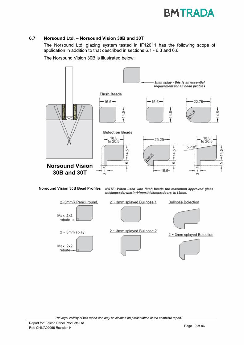
6.7 Norsound Ltd. – Norsound Vision 30B and 30T
The Norsound Ltd. glazing system tested in IF12011 has the following scope of application in addition to that described in sections 6.1 - 6.3 and 6.6:
The Norsound Vision 30B is illustrated below:
Norsound Vision
30B and 30T
Norsound Vision 30B Bead Profiles

The legal validity of this report can only be claimed on presentation of the complete report.
Report for: Falcon Panel Products Ltd. Page 11 of 86
Ref: Chilt/A02066 Revision K
The Norsound Vision 30T may utilise the same range of bead shapes and are illusatrated below:
1. Bead height must be nominally 14.5mm.
2. The intumescent seal component of Norsound Vision 30B and 30T is 15mm high and is required to project 0.5mm above the sightline of the bead.
3. The position of the groove in the rear of the bead is therefore critical for installation of Norsound Vision 30T.
4. Bolection returns should be a minimum of 5mm high, and a minimum of 3mm thick (projecting from the leaf face).
5. Glazing beads must be retained in position with, minimum, 40mm long x 1.5mm diameter steel pins or, minimum, 40mm long No. 6-8 screws, inserted at 35-40º to the vertical at no more than 40mm from each corner and at 150mm maximum centres.
6. Pneumatically fired pins are acceptable providing the pins meet the specification given above.
The bead material must meet the following specification and can be used with glass types 1-4 and 9-19 listed in section 6.2.
Material Min. Density
(kg/m³)
Straight grained joinery quality softwood, free from knots, splits & checks 510
Straight grained joinery quality hardwood, free from knots, splits & checks 510
MDF 700
Norsound Vision 30T Flush Bead Types
Norsound Vision 30T Bolection Bead Types

The legal validity of this report can only be claimed on presentation of the complete report.
Report for: Falcon Panel Products Ltd. Page 12 of 86
Ref: Chilt/A02066 Revision K
6.8 Norsound Ltd. – Norsound Universal 30B and 30T
The Norsound Ltd. Universal glazing system has the following scope of application in addition to that described in sections 6.1 - 6.3 and 6.6:
The Norsound Universal 30B is illustrated below:
The Norsound Universal 30T glazing system has the following scope of application in addition to that described in sections 6.1 - 6.3 and 6.6:
The Norsound Universal 30T is illustrated below:
Maximum glass thickness = 10mm
Maximum glass thickness = 10mm

The legal validity of this report can only be claimed on presentation of the complete report.
Report for: Falcon Panel Products Ltd. Page 13 of 86
Ref: Chilt/A02066 Revision K
1. Bead height must be nominally 13mm.
2. The intumescent seal component of Norsound Universal 30B and 30T is 15mm high and is required to project 0.5mm above the sightline of the bead.
3. The position of the groove in the rear of the bead is therefore critical for installation of Norsound Universal 30T.
4. Glazing beads must be retained in position with minimum 40mm long x 1.5mm diameter steel pins or, minimum, 40mm long No. 6-8 screws, inserted at 35-40º to the vertical at no more than 40mm from each corner and at 150mm maximum centres.
5. Pneumatically fired pins are acceptable providing the pins meet the specification given above.
6. The Norsound Universal aluminium section cladding the timber bead must be secured to the core bead by use of 3No. 10-12mm No. 4 grub screws per length.
7. The intumescent seal must project nominally 0.5mm above the sight line of the beading.
The bead material must meet the following specification and can be used with glass types 1-4 and 9-19 listed in section 6.2.
Material Min. Density
(kg/m³)
Straight grained joinery quality softwood, free from knots, splits & checks 510
Straight grained joinery quality hardwood, free from knots, splits & checks 510
MDF 700

The legal validity of this report can only be claimed on presentation of the complete report.
Report for: Falcon Panel Products Ltd. Page 14 of 86
Ref: Chilt/A02066 Revision K
7 Overpanels
7.1 Solid
Overpanels of the same construction as the door leaves may be used either flush with the leaf heads or when separated by a transom. In either case the overpanel must be fully contained within the door frame (see following diagram).
If a transom is required to separate the leaf heads from the overpanel, it must be to the same specification as the door frame (see the note under the table in section 9.1).
Door frame joints must utilise one of the following four methods: mortise and tenon joints; half lapped joints; mitre joints; butt joints (see section 9.2).
All methods require joints to be tight, with no gaps, and require mechanical fixing with the appropriate size ring shank nails or screws. Butt joints must be additionally bonded with urea formaldehyde or equivalent.
The overpanels must be fixed by screwing through the rear of the frame with steel screws passing at least 30mm into the centre line of the overpanel. Fixings must be no more than 100mm from each corner and a maximum of 250mm centres in between. The intumescent seals specified for the jambs in Appendix E, must also be fitted to all concealed edges of the overpanel. The seals may be fitted in the overpanel edges or alternatively in the frame reveal. A maximum 2mm gap is permitted between the edge of the overpanel and the frame reveal.
It is permitted to include a glazed aperture within the overpanel providing the glazing is within the parameters given in section 6 and the overpanel is fitted with a transom.
Maximum overpanel heights are as follows:
Configuration Max. Overpanel Height (mm)
Single doorsets 2000
Double doorsets 1500
Note: Drawing is representative of doorset construction only; actual construction must be as the text within this document specifies.
Transom
Overpanel fixings
Leaf head
Intumescent seals
The legal validity of this report can only be claimed on presentation of the complete report.
Report for: Falcon Panel Products Ltd. Page 15 of 86
Ref: Chilt/A02066 Revision K
8 Fanlights and Sidescreens
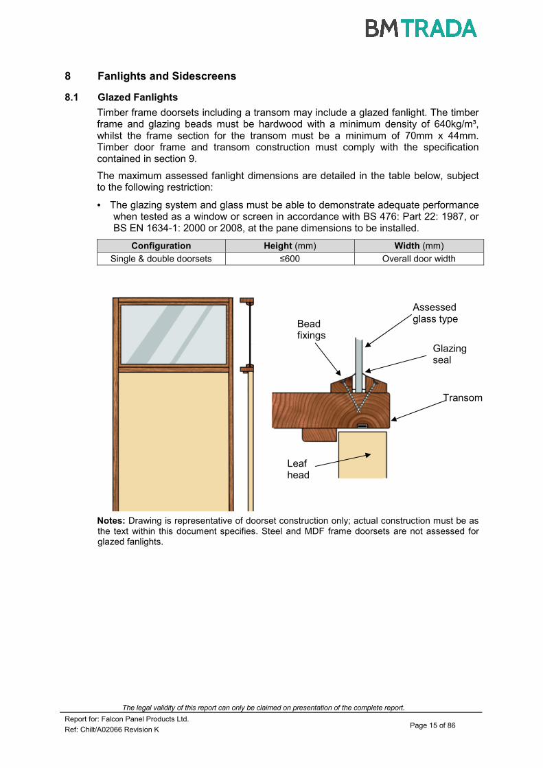
8.1 Glazed Fanlights
Timber frame doorsets including a transom may include a glazed fanlight. The timber frame and glazing beads must be hardwood with a minimum density of 640kg/m³, whilst the frame section for the transom must be a minimum of 70mm x 44mm. Timber door frame and transom construction must comply with the specification contained in section 9.
The maximum assessed fanlight dimensions are detailed in the table below, subject to the following restriction:
• The glazing system and glass must be able to demonstrate adequate performance when tested as a window or screen in accordance with BS 476: Part 22: 1987, or BS EN 1634-1: 2000 or 2008, at the pane dimensions to be installed.
Configuration Height (mm) Width (mm)
Single & double doorsets ≤600 Overall door width
Notes: Drawing is representative of doorset construction only; actual construction must be as the text within this document specifies. Steel and MDF frame doorsets are not assessed for glazed fanlights.
Assessed glass type
Bead fixings
Glazing seal
Transom
Leaf head
The legal validity of this report can only be claimed on presentation of the complete report.
Report for: Falcon Panel Products Ltd. Page 16 of 86
Ref: Chilt/A02066 Revision K
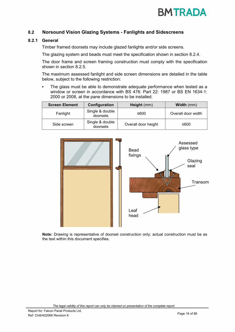
8.2 Norsound Vision Glazing Systems - Fanlights and Sidescreens
8.2.1 General
Timber framed doorsets may include glazed fanlights and/or side screens.
The glazing system and beads must meet the specification shown in section 8.2.4.
The door frame and screen framing construction must comply with the specification shown in section 8.2.5.
The maximum assessed fanlight and side screen dimensions are detailed in the table below, subject to the following restriction:
• The glass must be able to demonstrate adequate performance when tested as a window or screen in accordance with BS 476: Part 22: 1987 or BS EN 1634-1: 2000 or 2008, at the pane dimensions to be installed.
Screen Element Configuration Height (mm) Width (mm)
Fanlight Single & double
doorsets ≤600 Overall door width
Side screen Single & double
doorsets Overall door height ≤600
Note: Drawing is representative of doorset construction only; actual construction must be as the text within this document specifies.
Assessed glass type
Bead fixings
Glazing seal
Transom
Leaf head

The legal validity of this report can only be claimed on presentation of the complete report.
Report for: Falcon Panel Products Ltd. Page 17 of 86
Ref: Chilt/A02066 Revision K
8.2.2 Common Frame Sections
The following drawings depict possible constructions of common frame sections for screens and door frame jambs:
Door leaf
Option 1 - One frame section
Option 2 - Back to back frame section
Option 3 - Back to back frame section with separating post, which may be rebated a maximum of 5mm as shown
Door leaf
Door leaf
The legal validity of this report can only be claimed on presentation of the complete report.
Report for: Falcon Panel Products Ltd. Page 18 of 86
Ref: Chilt/A02066 Revision K
When using separate sections of timber, as shown above (options 2 and 3), each section must be suitably fixed to one-another using appropriate steel screw fixings and glued using Urea Formaldehyde or polyurethane. Screws must be fixed at 600mm centres and locate to approx 2/3 depth of the adjacent timber section. The overall frame section and material must match that given in this assessment for each glass type and glazing specification. Joints must be tight with no gaps.
It is permitted to include maximum 3mm (w) x 3mm (d) quirks/pencil rounds at the junction of each timber section for options 2 and 3.
Drawings are representative of each type of common frame section makeup; actual construction in terms of intumescent seal location and material, etc. must be as the text within this document specifies.
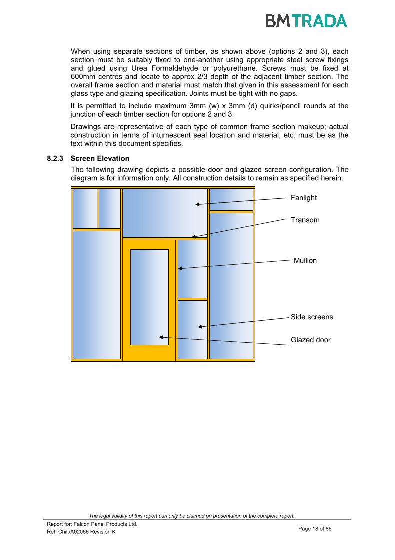
8.2.3 Screen Elevation
The following drawing depicts a possible door and glazed screen configuration. The diagram is for information only. All construction details to remain as specified herein.
Fanlight
Transom
Mullion
Side screens
Glazed door

The legal validity of this report can only be claimed on presentation of the complete report.
Report for: Falcon Panel Products Ltd. Page 19 of 86
Ref: Chilt/A02066 Revision K
8.2.4 Glazing Beads and Installation
Glazing beads and intumescent materials must be installed in line with the following sections.
System Name Norsound Vision 30B Norsound Vision 30T
Typical Installation
Dimensions
Bead Height Nominally 14.5 Nominally 14.5
Intumescent Seal(s)
15 high x 3 thick 15 high x 3 thick
plus ‘plug’
Aperture Liner Not required
8.2.5 Norsound Vision 30B & 30T Applications
The following bead designs are assessed as acceptable:
Norsound Vision Flush Bead Types

The legal validity of this report can only be claimed on presentation of the complete report.
Report for: Falcon Panel Products Ltd. Page 20 of 86
Ref: Chilt/A02066 Revision K
Norsound Vision 30T may utilise the same range of bead shapes.
Notes:
1. Bead height must be nominally 14.5mm.
2. The intumescent seal component of Norsound Vision 30B and 30T is 15mm high and is required to project 0.5mm above the sightline of the bead.
3. The position of the groove in the rear of the bead is therefore critical for installation of Norsound Vision 30T.
4. Glazing beads must be retained in position with, minimum, 40mm long x 1.5mm diameter steel pins or, minimum, 40mm long No. 6-8 screws, inserted at 35-40º to the vertical at no more than 40mm from each corner and at 150mm maximum centres.
5. Pneumatically fired pins are acceptable providing the pins meet the specification given above.
8.2.6 Glazing Bead Material
All timber for glazing beads must be straight grained, joinery quality (MDF, softwood or hardwood as specified in the table below), free from knots, splits and checks.
Integrity Performance
Bead Profile Material Min. Density (kg/m3)
30 All in section 8.2.5
Softwood 510
Hardwood
MDF 700
Norsound Vision Flush Bead Types

The legal validity of this report can only be claimed on presentation of the complete report.
Report for: Falcon Panel Products Ltd. Page 21 of 86
Ref: Chilt/A02066 Revision K
8.2.7 Timber Screen Framing
Timber used for constructing framing elements comprising screen assemblies as illustrated in section 8.2 must meet the following specification.
Door frame jambs and transoms must meet the requirements stipulated within the supporting documentation for the relevant door leaf as specified.
Integrity Performance
Material Minimum Section Size
2
(mm) Min. Density (kg/m
3)
30 Softwood
70 x 32 510 Hardwood
Notes:
1. These timber sections can be used for the perimeter framing of the screen and the transoms separating individual panes of glass within the fanlights and side screens.
2. Mullions must be minimum 40mm thick for both 30 minutes integrity performance.
3. The fanlights and side screens may comprise multiple panes of glass providing the total doorset and screen assembly does not exceed 2950mm high and the transom/ mullion restrictions above are complied with.
4. Gaps between glass and framing, to permit expansion, should be set according to the glass manufacturer’s information, using non combustible or hardwood setting blocks at the bottom edge.
9 Door Frames
9.1 Timber Based Door Frame Construction
Timber based door frames for the door leaf designs referred to in sections 2.1 - 2.4 of this assessment must be constructed to meet the following specification (for steel door frame options see Appendices A1 & A2):
Material Section Size (mm) Min. Density (kg/m3)
Softwood or hardwood 70 x 25* (excluding the stop) 450
MDF 70 x 25 (excluding the stop) 700
*If the doorset features a transomed overpanel, the door frame must be softwood or hardwood with a minimum section of 70mm x 30mm.
All door frame timber must meet or exceed class J30 as specified in BS EN 942: 2007 (subject to adequate repair of any defects).
A 12mm deep planted stop is adequate for single acting frames whilst double acting frames may be scalloped or square (see diagram below).
Frame joints may be mortice and tenoned, mitred, half lapped or butted and with no gaps (see section 8.2). All jointing methods require mechanical fixing with the appropriate size ring shank nails or screws.

The legal validity of this report can only be claimed on presentation of the complete report.
Report for: Falcon Panel Products Ltd. Page 22 of 86
Ref: Chilt/A02066 Revision K
The following diagram depicts the assessed frame profiles and dimensions:
9.2 Door Frame Joints
Half Lapped Joint Mitre Joint
A = min. 70mm B = min. 25mm (see table above) C = min. 12mm R = radius from floor spring 8mm radius to create maximum 2mm edge profiling
Standard Scalloped Profiled Edges

The legal validity of this report can only be claimed on presentation of the complete report.
Report for: Falcon Panel Products Ltd. Page 23 of 86
Ref: Chilt/A02066 Revision K
Mortise and Tenon Joint Butt Joint
Note: Drawing is representative of each type of door frame joint; actual construction in terms of intumescent seal location and material, etc. must be as the text within this document specifies.
9.3 Door Frame Installation
The following diagrams indicate acceptable and unacceptable door frame installations:
6 to 10mm
Max 10 x 10mm shadow gap with 2mm
intumescent mastic capping or
10 x 4mm PVC encased intumescent seal
15mm
Permitted Permitted
PermittedNot PermittedNot Permitted
Permitted
Notes: Drawing is representative of door frame installation; actual installation must be as the text within this document specifies. See section 19 for sealing to structural opening specification.
For shadow detail depicted (top right) the sub-frame material must be the same material as approved for the door frame, or a non-combustible board, tightly fitted and with no gaps.

The legal validity of this report can only be claimed on presentation of the complete report.
Report for: Falcon Panel Products Ltd. Page 24 of 86
Ref: Chilt/A02066 Revision K
10 Facings
10.1 General
The facings for Strebord 44 and Strebord Superpan are integral with the core construction and therefore alternative materials are not permitted. However, a range of facing options has been assessed for the Strebord 35+ and 38+ designs as follows:
Facing Material
Door Leaf Design Max. Permitted Thickness (mm)
Min. Density (kg/m³)
MDF Strebord 35+ & Strebord 38+ 4 700
Chipboard Strebord 35+ & Strebord 38+ 4 640
Plywood Strebord 35+ & Strebord 38+ 4 640
10.2 Decorative and Protective Facings
The following additional facing materials are permitted for this door design since they would degrade rapidly under test conditions without significant effect:
Facing Materials Max. Permitted Thickness (mm)
Paint 0.5
Timber veneers 2
PVC/Plastic laminates 2
Decorative paper/Non-metallic foil 0.5
Notes:
1. Metallic facings are not permitted except for push plates and kick plates.
2. The door leaf thickness may be reduced by a total maximum of 0.5mm for calibration purposes in order to accommodate the chosen finish.
3. Materials must not conceal intumescent strips.
4. PVC/Plastic laminates may only be applied to leaf edges meeting the specification given in section 11.2.
10.3 Decorative Grooves
10.3.1 Groove Option 1
The door leaf designs referred to in sections 2.1, 2.2 and 2.4 of this assessment may be grooved to the following specification:
Element Details
Max. groove size (mm) 10 wide x 4 deep
Proximity to door edges (mm) Horizontal grooves
≥ 100 from top and bottom
Vertical grooves ≥ 100 from sides
Groove spacing (mm) ≥ 100
Orientation Vertical or horizontal
Configuration Latched and unlatched, single and double
acting, single and double leaf doorsets
Leaf size range (mm) 2150 high x 926 wide
Intumescent seal dimensions (mm) ≥ to 15 x 4
A maximum of 4No. vertical and 4No. horizontal grooves are permitted perpendicular to one another, providing all other details meet the specification given in the table above.

The legal validity of this report can only be claimed on presentation of the complete report.
Report for: Falcon Panel Products Ltd. Page 25 of 86
Ref: Chilt/A02066 Revision K
10.3.2 Groove Option 2 (Applicable to Strebord 44 only (Section 2.3))
The testing conducted on Strebord 44 under test RF11160 demonstrated that material could be removed from both faces of the door leaf without negating integrity performance. It is therefore permitted to groove/recess both faces of the door leaf with any decorative pattern subject to the following provisos:
1. The total surface area of grooves/recess on any one face must not exceed 30% of the leaf face area.
2. It is not necessary to apply any additional material to the bottom of the groove/recess providing the depth of the groove/recess does not exceed 7mm.
3. It is permitted to go to a maximum depth of 10mm providing a minimum thickness of 3mm material is applied to the bottom of the groove/recess.
4. The permitted infill materials for the groove/recess are MDF (min. density 700kg/m³), or hardwood (min. density 600kg/m³).
5. The infill materials must be glued in position using either UF, PVA or PU adhesives.
6. It is permitted to groove/recess the infill providing a minimum of 3mm of infill material remains in the bottom of the groove/recess.
7. Grooves/recess may run to the leaf edge.
8. Horizontal grooves must be no closer than 75mm to the top and bottom of the door leaf.
9. Vertical grooves must be no closer than 75mm to the sides of the leaf.
10. The groove/recess must not coincide with any apertures (e.g. glazing, air transfer grilles, letter plates, etc.), i.e. the groove or recess must stop 5mm short of the aperture cut-out.
10.3.3 Strebord Panelled Design
For further Strebord grooved and panelled options refer to the latest revision of Falcon Panel Products global assessment referenced Chilt/A09104.

The legal validity of this report can only be claimed on presentation of the complete report.
Report for: Falcon Panel Products Ltd. Page 26 of 86
Ref: Chilt/A02066 Revision K
11 Intumescent Materials
The intumescent materials tested and assessed for these doorset designs are as follows:
Application Location Product/Manufacturer
Edge seals
Fitted in the frame jambs or leaf edges
1. PVC encapsulated Palusol 100 – Mann McGowan Fabrications Ltd. or Lorient Polyproducts Ltd.
2. Therm-A-Seal – Intumescent Seals Ltd.
3. Pyroplex - Pyroplex Ltd.
4. Type 617 - Lorient Polyproducts Ltd.
Fitted in the frame reveal (not approved
as a seal for overpanel edges)
1. Norfast – Norsound Ltd.
Hinges Under all hinge blades for doorsets greater than 2670mm high
1. 1mm Interdens – Dufaylite Developments Ltd.
2. 1mm MAP paper – Lorient Polyproducts Ltd.
3. 1mm Pyrostrip 300 – Mann McGowan Fabrications Ltd.
4. 1mm Therm-A-Strip – Intumescent Seals Ltd.
5. 1mm NOR910 – Norsound Ltd.
Lock/latches Under forend & keep for double doorsets
only
1. 1mm Interdens – Dufaylite Developments Ltd.
2. 1mm MAP paper – Lorient Polyproducts Ltd.
3. 1mm Pyrostrip 300 – Mann McGowan Fabrications Ltd.
4. 1mm Therm-A-Strip –Intumescent Seals Ltd.
5. 1mm NOR910 – Norsound Ltd.
Top pivots & flush bolts
Lining all sides of the mortices
1. 2mm Interdens – Dufaylite Developments Ltd.
2. 2mm MAP paper – Lorient Polyproducts Ltd.
3. 2mm Therm-A-Strip –Intumescent Seals Ltd.
4. 2mm Therm-A-Flex – Intumescent Seals Ltd.
5. 2mm NOR920 – Norsound Ltd.
The seal specification for each configuration is contained in Appendix E.

The legal validity of this report can only be claimed on presentation of the complete report.
Report for: Falcon Panel Products Ltd. Page 27 of 86
Ref: Chilt/A02066 Revision K
12 Lippings
12.1 Timber Lippings
The door leaf designs referred to in sections 2.1 - 2.4 of this assessment must be lipped in accordance with the following specification. The lipping specifications for steel frame doorsets are contained in Appendices A1 and A2.
Material Size (mm) Min. Density
(kg/m3)
Timber must be hardwood, straight grained, joinery quality, free from knots, splits and checks
1. Flat = 6–19 thick with a maximum of 2mm profiling permitted at corners of lipping (see section 9.1)
2. Rounded = 8–19 thick with a radius matching the distance between leaf edge and floor pivot (see section 9.1)
3. Rebated = 20–25 thick with a 12mm deep equal rebate
530
(see note 6)
Notes:
1. Single and double doorsets without overpanels only require lipping on the vertical edges but may be additionally lipped on the top and bottom edges if required.
2. Doorsets with overpanels must be lipped on the vertical edges and additionally at the bottom edge of the overpanel and top edge of the doors.
3. Double doorsets without flush overpanels may use square or rebated meeting edges.
4. Double doorsets with flush overpanels may use a square or rebated overpanel junction but only in conjunction with square meeting edges.
5. A 2.50 chamfer is permitted to the lipping at the leading edge of leaves providing the door
gaps meet the requirements of section 16.
6. All rebated lippings and flat and rounded lippings thicker than 13mm must be constructed from hardwood timber of minimum 640kg/m
3 density.
12.2 PVC Edge Protectors and Post-Formed CS Group Acrovyn
12.2.1 General
It is possible to fit proprietary edge protectors to this doorset design providing they have suitable supporting test evidence to BS 476: Part 22: 1987 or BS EN 1634-1: 2000 or 2008, when fitted to timber doorsets of similar construction to this design. The end user must satisfy themselves that the test evidence supports the proposed end use application.
12.2.2 CS Group Edge Protectors
The Falcon Strebord designs have been assessed for use with CS Group edge protectors. CS Group edge protectors are supplied pre-formed with the approved intumescent material. The CS Group edge protectors must be used as part of a complete intumescent system and the required intumescent specification and leaf sizes are given in the relevant data sheets in appendix E. CS Group must be contacted for precise installation and fixing details (www.c-sgroup.co.uk).

The legal validity of this report can only be claimed on presentation of the complete report.
Report for: Falcon Panel Products Ltd. Page 28 of 86
Ref: Chilt/A02066 Revision K
12.2.3 Post-Formed CS Group Acrovyn
It is possible to encapsulate the Falcon Strebord designs by post-forming the leaf in CS Group Acrovyn, based on the supporting test evidence in Chilt/RF11059 and the following specification:
1. CS Group Acrovyn must be wrapped around the vertical edges of the leaf only, i.e. the top and bottom of the leaf must remain exposed.
2. The vertical edge detail prior to post-forming must either be lipped with 8mm thick PVC, or hardwood as detailed in this assessment (see section 12.1).
3. The maximum radius of the lipping at the corners of the vertical edges before post-forming must be 9mm, which provides for 11mm external radius after the CS Group Acrovyn has been applied.
4. The intumescent detail as specified in section 11 and the relevant (CS Group headed) datasheets contained in appendix E of this assessment must be replicated.
5. CS Group Acrovyn must be bonded to the leaf using 3M Scotch-Grip cement 10 contact adhesive, or equivalent.
6. See relevant (CS Group headed) data sheets in appendix E of this assessment for maximum permitted leaf sizes.
7. The maximum thickness of CS Group Acrovyn used must be 2mm, as per test evidence.
8. The CS Group Acrovyn can be provided as pre-formed trays with dimensions to suit the proposed leaf sizes, as well as sheets for post-forming by the door manufacturer.
12.3 Hardwood Blocking for Pivots
The following option is permitted for lipping the top and bottom of doors that are to receive pivot fixings and are to be used in severe duty locations (diagram below).
The hardwood insert needs to be a size suited to the particular item of hardware plus a maximum of 50mm (not full door width) and must be securely adhered to the door core. The hardwood insert should not be greater than 15mm in depth and when fitted should provide for a minimum margin of 8mm on either face. The inserted blocks must be bonded on all contact faces using adhesives approved for the application of lippings (see section 13). The hardwood insert must meet the minimum density requirements as given in the table in section 12.1.

The legal validity of this report can only be claimed on presentation of the complete report.
Report for: Falcon Panel Products Ltd. Page 29 of 86
Ref: Chilt/A02066 Revision K
12.4 Meeting Stile Astragals
Generally fire doors should be able to open simultaneously. However, where additional performances are required (e.g. acoustic performances) it may be necessary to provide for sequential opening.
The astragal detail may be used where these conditions apply, without adverse influence on existing fire test/assessment data.
Astragals can be applied to both door leaves provided a suitable door selector is fitted and may be profiled for aesthetic effect providing they meet the minimum specification given below.
The hardwood for the astragal must be hardwood of the same minimum density being used for the lipping material. See following diagram:
13 Adhesives
The adhesives used in construction are as follows:
Element Product
Core Manufacturers specification
Lipping Urea formaldehyde, polyurethane or PVA
35+, 38+ and Superpan Facings PVA

The legal validity of this report can only be claimed on presentation of the complete report.
Report for: Falcon Panel Products Ltd. Page 30 of 86
Ref: Chilt/A02066 Revision K
14 Tested Hardware
The following hardware has been successfully incorporated in the tests on the door leaf designs referred to in sections 2.1 – 2.4 of this assessment:
Element Manufacturer and Product Reference
Hinges
1. Royde & Tucker H101 lift-off type hinges
2. Royde & Tucker H102 lift-off type hinges
3. Royde & Tucker H105 lift-off type hinges
Closers
1. Dorma TS73V overhead closer
2. Dorma TS71 overhead closer
3. Briton 1110 overhead closer
4. Rutland TS3204 overhead closer
Furniture
1. Henderson Hardware mortice latch with aluminium lever handles
2. E*S Standard tubular mortice latch with aluminium lever handles
3. Arrone 3 Lever mortice latch with aluminium lever handles
15 Additional & Alternative Hardware
15.1 Automatic Closing
Automatic closing devices must either be as tested or components of equal specification that have demonstrated contribution to the required performance of these types of 30 minute doorset designs, when tested to BS 476: Part 22: 1987 or BS EN 1634-1: 2000 or 2008.
Note: The top pivots to floorspring assemblies must be protected with 2mm thick intumescent gasket (see section 11) or alternatively the manufacturers tested intumescent pack.
15.2 Latches & Locks
Latches and locks must either be as tested, or alternatively components with the following specification are acceptable:
Element Specification
Maximum forend and strike plate dimensions
235mm high by 25mm wide by 4mm thick
Maximum body dimensions 18mm thick by 100mm wide by 165mm high
Intumescent protection See section 11
Materials All parts essential to the locking/latching action (including the latch bolt, forend and strike) to be steel, stainless steel or brass (melting point ≥800
oC)
Location Between 1000mm and 1200mm from the threshold
The legal validity of this report can only be claimed on presentation of the complete report.
Report for: Falcon Panel Products Ltd. Page 31 of 86
Ref: Chilt/A02066 Revision K
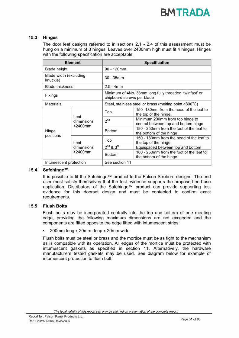
15.3 Hinges
The door leaf designs referred to in sections 2.1 - 2.4 of this assessment must be hung on a minimum of 3 hinges. Leaves over 2400mm high must fit 4 hinges. Hinges with the following specification are acceptable:
Element Specification
Blade height 90 - 120mm
Blade width (excluding knuckle)
30 - 35mm
Blade thickness 2.5 - 4mm
Fixings Minimum of 4No. 38mm long fully threaded ‘twinfast’ or chipboard screws per blade
Materials Steel, stainless steel or brass (melting point ≥800oC)
Hinge positions
Leaf dimensions <2400mm
Top 150 -180mm from the head of the leaf to the top of the hinge
2nd
Minimum 200mm from top hinge to central between top and bottom hinge
Bottom 180 - 250mm from the foot of the leaf to the bottom of the hinge
Leaf dimensions >2400mm
Top 150 - 180mm from the head of the leaf to the top of the hinge
2nd
& 3rd
Equispaced between top and bottom
Bottom 180 - 250mm from the foot of the leaf to the bottom of the hinge
Intumescent protection See section 11
15.4 Safehinge™
It is possible to fit the Safehinge™ product to the Falcon Strebord designs. The end user must satisfy themselves that the test evidence supports the proposed end use application. Distributors of the Safehinge™ product can provide supporting test evidence for this doorset design and must be contacted to confirm exact requirements.
15.5 Flush Bolts
Flush bolts may be incorporated centrally into the top and bottom of one meeting edge, providing the following maximum dimensions are not exceeded and the components are fitted opposite the edge fitted with intumescent strips:
• 200mm long x 20mm deep x 20mm wide
Flush bolts must be steel or brass and the mortice must be as tight to the mechanism as is compatible with its operation. All edges of the mortice must be protected with intumescent gaskets as specified in section 11. Alternatively, the hardware manufacturers tested gaskets may be used. See diagram below for example of intumescent protection to flush bolt:

The legal validity of this report can only be claimed on presentation of the complete report.
Report for: Falcon Panel Products Ltd. Page 32 of 86
Ref: Chilt/A02066 Revision K
15.6 Pull Handles
Handles may be surface-fixed or bolted through the door leaf, providing they are steel or brass and the length is limited to 1200mm between the fixing points. If through fixed, there must be no more than 1mm clearance between the hole and stud.
15.7 Push Plates/Kick Plates
Steel, stainless steel or brass plates are permitted up to a maximum of 20% of the door leaf area if mechanically fixed and a maximum of 30% if bonded with a contact or other thermally softening adhesive. Plates must not return around the door edges.
Kick plates (to a maximum size of 250mm high x 2mm thick) and finger plates (to a maximum size of 300mm high x 160mm wide x 2mm thick) may be recessed flush with the face and fitted on one or both sides of the leaf.
15.8 Door Selectors
These may be freely applied, provided that they are not invasive in the leaf edges or door frames and they do not interfere with the self-closing action of the door leaf. Products that are invasive will require fire resistance test/assessment evidence to support their use.
15.9 Door Security Viewers
Door security viewers with brass or steel bodies of a diameter less than or equal to 15mm may be used provided that the through-hole is bored tight to the case of the viewer (maximum tolerance +1mm). Lenses must be glass and the item must be bedded into a tested intumescent mastic.
15.10 Panic Hardware
Panic hardware may be fitted, provided that its installation does not require the removal of any timber from the leaf, stop or frame reveal and it in no way interferes with the self-closing action of the door leaf.
Intumescent gaskets
Flush bolt mechanism
Door leaf
The legal validity of this report can only be claimed on presentation of the complete report.
Report for: Falcon Panel Products Ltd. Page 33 of 86
Ref: Chilt/A02066 Revision K
15.11 Air Transfer Grilles
15.11.1 General
Air transfer grilles may be fitted providing the product has suitable test evidence to BS 476: Part 22: 1987 or BS EN 1634-1: 2000 or 2008, that demonstrates a minimum 30 minutes integrity performance when installed within a timber based doorset of comparable thickness. Margins to the leaf edges will remain as detailed for glazing and the position of the unit will be dictated by the pressure regime tested in the proving evidence (normally below mid height). The area occupied by the air transfer grille must not exceed 0.2m2 and must be deducted from the percentage of glazing, if both elements are fitted.
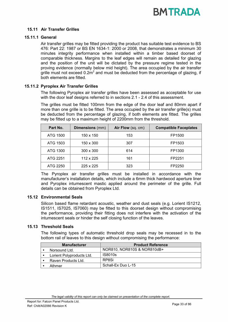
15.11.2 Pyroplex Air Transfer Grilles
The following Pyroplex air transfer grilles have been assessed as acceptable for use with the door leaf designs referred to in sections 2.1 - 2.4 of this assessment.
The grilles must be fitted 100mm from the edge of the door leaf and 80mm apart if more than one grille is to be fitted. The area occupied by the air transfer grille(s) must be deducted from the percentage of glazing, if both elements are fitted. The grilles may be fitted up to a maximum height of 2200mm from the threshold.
Part No. Dimensions (mm) Air Flow (sq. cm) Compatible Faceplates
ATG 1500 150 x 150 153 FP1500
ATG 1503 150 x 300 307 FP1503
ATG 1300 300 x 300 614 FP1300
ATG 2251 112 x 225 161 FP2251
ATG 2250 225 x 225 323 FP2250
The Pyroplex air transfer grilles must be installed in accordance with the manufacturer’s installation details, which include a 6mm thick hardwood aperture liner and Pyroplex intumescent mastic applied around the perimeter of the grille. Full details can be obtained from Pyroplex Ltd.
15.12 Environmental Seals
Silicon based flame retardant acoustic, weather and dust seals (e.g. Lorient IS1212, IS1511, IS7025, IS7060) may be fitted to this doorset design without compromising the performance, providing their fitting does not interfere with the activation of the intumescent seals or hinder the self closing function of the leaves.
15.13 Threshold Seals
The following types of automatic threshold drop seals may be recessed in to the bottom rail of leaves to this design without compromising the performance:
Manufacturer Product Reference
• Norsound Ltd. NOR810, NOR810S & NOR810dB+
• Lorient Polyproducts Ltd. IS8010s
• Raven Products Ltd. RP8Si
• Athmer Schall-Ex Duo L-15

The legal validity of this report can only be claimed on presentation of the complete report.
Report for: Falcon Panel Products Ltd. Page 34 of 86
Ref: Chilt/A02066 Revision K
15.14 Cable-Way
Based on the integrity performance of the doorset construction, with no burn through of the core material, we consider it acceptable to allow the provision for a concealed cable-way to facilitate electro-magnetic closing/latching mechanisms. The cable-way must be concealed in the following way:
1. A hole drilled centrally through the leaf of maximum 10mm diameter.
2. The cable for the electronic closing/latching mechanisms must be no more than 2mm smaller in diameter than the hole through the leaf.
3. The cable for the electronic closing/latching mechanism must be PVC encased.
4. Cable ways are only permitted for use with latched, single leaf, single acting doorsets with maximum leaf dimensions of 2100mm (h) x 900mm (w).
5. The hole must be located below 1500mm from the threshold and must be spaced a minimum of 90mm from any apertures within the leaf, e.g. glazing, air transfer grilles or letter plates, etc.
This approval is subject to the hardware manufacturer having the appropriate test evidence for the product for use with this type of 30 minute construction. Test evidence generated in steel doorsets is not acceptable. Any tested intumescent gaskets for the lockset, closing mechanism, receiver plate, cable loops, etc. must be replicated.
15.15 Letter Boxes/Plates
Letter boxes/plates may be fitted providing the product has demonstrated contribution to the required integrity performance of these types of doorset designs, when tested to BS 476: Part 22: 1987 or BS EN 1634-1: 2000 or 2008, when installed in a timber based doorset of comparable thickness. Products may be fitted up to 1200mm from floor level and not closer than 100mm to any leaf edge.
15.16 Identification Plates
Plastic or metal fire safety signs may be glued or screwed to the face of the door leaves. The signage must comply with BS 5499-5: 2002 according to whether the door is:
a) To be kept closed when not in use (Fire Door Keep Shut).
b) To be kept locked shut when not in use (Fire Door Keep Locked Shut).
c) Held open by an automatic release mechanism or free swing device (Automatic Fire Door Keep Clear).
It is also permitted to fit aluminium (max. thickness 2mm) or PVC (max. thickness 3mm) identification plates, complying with HTM 58 – Internal Doorsets, HTM Building Component Series, NHS Estates. The signage must not exceed 45mm diameter and can be fitted flush with the leaf face, a minimum of 50mm from any edge.

The legal validity of this report can only be claimed on presentation of the complete report.
Report for: Falcon Panel Products Ltd. Page 35 of 86
Ref: Chilt/A02066 Revision K
16 Door Gaps
For fire resistance applications, door gaps and alignment tolerances must fall within the following range:
Location Dimensions
Door edge gaps Representative of those tested but as a guideline, a minimum of 2mm and a maximum of 4mm
Alignment tolerances Leaves must not be proud of each other or from the door frame by more than 1mm
Threshold 10mm between bottom of leaf and top of floor covering
17 Structural Opening
The supporting construction must provide the required level of fire resistance designated for the doorset design and be a suitable medium to permit adequate fixity.
18 Fixings
The frame jambs are to be fixed to the supporting construction using steel fixings at 600mm maximum centres. The fixings must be of the appropriate type for the supporting construction and must penetrate to a minimum depth of 40mm. It is not necessary to fix the frame head, although packers must be inserted.
19 Sealing to Structural Opening
The door frame to structural opening gap must be protected using one of the following methods:
1. Gaps up to 10mm must be sealed on both sides with a 10mm depth of acrylic intumescent mastic, fire tested for this application to BS 476: Part 22: 1987 or BS EN 1634-1: 2000 or 2008. Joint must be fitted with 15mm thick architraves overlapping at least 15mm each side.
2. Gaps between 10mm and 20mm must be tightly packed with mineral fibre capped on both sides with a 10mm depth of acrylic intumescent mastic, fire tested for this application to BS 476: Part 22: 1987 or BS EN 1634-1: 2000 or 2008. Architraves are optional.
Architrave for joints not filled with mineral wool and optional for filled joints
Frame fixing
Mineral fibre infill for joints exceeding 10mm
Acrylic intumescent mastic

The legal validity of this report can only be claimed on presentation of the complete report.
Report for: Falcon Panel Products Ltd. Page 36 of 86
Ref: Chilt/A02066 Revision K
3. Gaps up to 20mm filled with proprietary fire stopping product (e.g. expanding PU foam or preformed compressible intumescent foam). Products must be tested for this application to BS 476: Part 22: 1987 or BS EN 1634-1: 2000 or 2008. Joint must be fitted with 15mm thick architraves overlapping at least 15mm each side.
4. Timber based or non-combustible subframe up to 50mm thick, with no gaps between the components. Joint must be fitted with 15mm thick architraves overlapping at least 15mm each side.
5. Timber based or non-combustible subframe up to 50mm thick, with gaps up to 10mm between the components filled on both sides with 10mm depth of acrylic intumescent mastic or full depth expanding PU foam, fire tested for this application to BS 476: Part 22: 1987 or BS EN 1634-1: 2000 or 2008. Joint must be fitted with 15mm thick architraves overlapping at least 15mm each side.
Guidance for various methods of sealing the frame to structural opening gap is also given in BS 8214: 2008, “Code of practice for fire door assemblies”, which may be referred to where appropriate.
Note: Drawings are representative of doorset installation only; actual installations must be as the text within this document specifies.
15mm thick architrave
10mm of acrylic intumescent mastic or full depth PU foam
Frame fixing
Fire stopping product
Frame fixing Architrave
Timber based or non-combustible subframe
Architrave
Fixing for subframe
Frame fixing
Sub frame fixing

The legal validity of this report can only be claimed on presentation of the complete report.
Report for: Falcon Panel Products Ltd. Page 37 of 86
Ref: Chilt/A02066 Revision K
20 Insulation
Insulation performance may be claimed for a doorset to one of these designs meeting the following criteria:
Type Details
Partially insulating Doorsets incorporating up to 20% of non-insulating glazing
Fully insulating Doorsets excluding metal frames and non-insulating glazing or including 30 minute insulating glazing (e.g. 15mm Pyrostop or 16mm Pyrobel)
21 Smoke Control
21.1 General
If the doorset design is required to provide a smoke control function to comply with Building Regulations, in the absence of a suitable pressurisation system, the doorset must meet one of the following criteria:
(a) have a leakage rate not exceeding 3m3/m/hour (head and jambs only) when tested at 25Pa under BS 476 Fire tests on building materials and structures, Section 31.1 - Methods for measuring smoke penetration through doorsets and shutter assemblies, Method of measurement under ambient temperature conditions; or
(b) meet the additional classification requirement of Sa when tested to BS EN 1634-3: 2004 - Fire resistance tests for door and shutter assemblies, Part 3 – Smoke control doors.
Smoke seals or combined intumescent/smoke seals that are fitted to the door to achieve the performance requirements specified above, must have been tested in accordance with the associated test method. Providing the smoke seals, any interruptions, door gaps, and the type/configuration of the doorset are consistent with the detail tested, the doorset will comply with current smoke control legislation under approved document B; and a suffix ‘S’ or ‘Sa’, as appropriate, may be added to the designation. Any other components installed where smoke leakage may occur must also be taken into account.
Note: The incorrect specification and fitting of smoke seals may impair the operation of a doorset and therefore compromise the fire resistance performance. Advice should be sought from the seal manufacturers regarding the correct specification and installation of smoke seals or combined smoke and intumescent seals.
21.2 Further Considerations
Note that there is other guidance available, including BS EN 9999-2008 - Code of practice for fire safety in the design, management and use of buildings, which may impose different or additional requirements, such as consideration of the gap between door leaf and threshold.
Responsibility for the appropriate smoke sealing specification and performance of the doors should be agreed between the relevant parties (i.e. specifier, manufacturer, contractor) prior to commencing manufacture and/or installation.

The legal validity of this report can only be claimed on presentation of the complete report.
Report for: Falcon Panel Products Ltd. Page 38 of 86
Ref: Chilt/A02066 Revision K
22 Conclusion
If the door leaf designs referred to in sections 2.1 - 2.4 of this assessment, constructed in accordance with the specifications documented in this global assessment, were to be tested in the appropriate configuration in accordance with BS 476: Part 22: 1987, it is our opinion that they would provide a minimum of 30 minutes integrity and insulation, subject to section 20.
The legal validity of this report can only be claimed on presentation of the complete report.
Report for: Falcon Panel Products Ltd. Page 39 of 86
Ref: Chilt/A02066 Revision K
23 Declaration by the Applicant
1. We the undersigned confirm that we have read and comply with obligations placed on us by FTSG Resolution No. 82: 2001.
2. We confirm that the component or element of structure, which is the subject of this assessment, has not to our knowledge been subjected to a fire test to the Standard against which this assessment is being made.
3. We agree to withdraw this assessment from circulation should the component or element of structure be the subject of a fire test to the Standard against which this assessment is being made.
4. We are not aware of any information that could adversely affect the conclusions of this assessment.
5. If we subsequently become aware of any such information we agree to ask the assessing authority to withdraw the assessment.
Signed: Name: For and on behalf of: Falcon Panel Products Ltd.

The legal validity of this report can only be claimed on presentation of the complete report.
Report for: Falcon Panel Products Ltd. Page 40 of 86
Ref: Chilt/A02066 Revision K
24 Limitations
The following limitations apply to this assessment:
1. This assessment addresses itself solely to the elements and subjects discussed and does not cover any other criteria. All other details not specifically referred to should remain as tested or assessed.
2. This assessment is issued on the basis of test data and information to hand at the time of issue. If contradictory evidence becomes available, BM TRADA reserves the right to withdraw the assessment unconditionally but not retrospectively.
3. This assessment has been carried out in accordance with Fire Test Study Group Resolution No. 82: 2001.
4. Opinions and interpretations expressed herein are outside the scope of UKAS accreditation.
5. This assessment relates only to those aspects of design, materials and construction that influence the performance of the element(s) under fire resistance test conditions. It does not purport to be a complete specification ensuring fitness for purpose and long-term serviceability. It is the responsibility of the client to ensure that the element conforms to recognised good practice in all other respects and that, with the incorporation of the guidance given in this assessment, the element is suitable for its intended purpose.
25 Validity
1. The assessment is valid initially for a period of five years from the date of issue, after which time it must be submitted to BM TRADA for technical review.
2. This assessment report is not valid unless it incorporates the declaration given in Section 23 duly signed by the applicant.
Signature:
Name: S Bailey P N Barker
Title: Product Assessor Senior Consultant
The legal validity of this report can only be claimed on presentation of the complete report.
Report for: Falcon Panel Products Ltd. Page 41 of 86
Ref: Chilt/A02066 Revision K
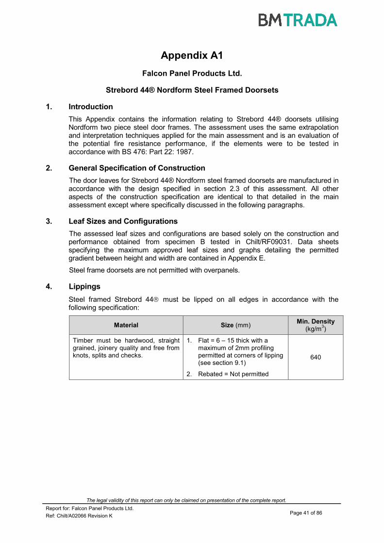
Appendix A1
Falcon Panel Products Ltd.
Strebord 44® Nordform Steel Framed Doorsets
1. Introduction
This Appendix contains the information relating to Strebord 44® doorsets utilising Nordform two piece steel door frames. The assessment uses the same extrapolation and interpretation techniques applied for the main assessment and is an evaluation of the potential fire resistance performance, if the elements were to be tested in accordance with BS 476: Part 22: 1987.
2. General Specification of Construction
The door leaves for Strebord 44® Nordform steel framed doorsets are manufactured in accordance with the design specified in section 2.3 of this assessment. All other aspects of the construction specification are identical to that detailed in the main assessment except where specifically discussed in the following paragraphs.
3. Leaf Sizes and Configurations
The assessed leaf sizes and configurations are based solely on the construction and performance obtained from specimen B tested in Chilt/RF09031. Data sheets specifying the maximum approved leaf sizes and graphs detailing the permitted gradient between height and width are contained in Appendix E.
Steel frame doorsets are not permitted with overpanels.
4. Lippings
Steel framed Strebord 44 must be lipped on all edges in accordance with the following specification:
Material Size (mm) Min. Density
(kg/m3)
Timber must be hardwood, straight grained, joinery quality and free from knots, splits and checks.
1. Flat = 6 – 15 thick with a maximum of 2mm profiling permitted at corners of lipping (see section 9.1)
2. Rebated = Not permitted
640

The legal validity of this report can only be claimed on presentation of the complete report.
Report for: Falcon Panel Products Ltd. Page 42 of 86
Ref: Chilt/A02066 Revision K
5. Door Frame Construction & Installation
The tested frame specification for doorsets to this design comprised the following:
Element Material Dimensions
(mm)
Head & jambs Profiled steel sections
Nordform Product Ref. A01-A02 1.5 thick
Head to jamb jointing detail Mitred – screwed -
Stops Integral 15 deep
Frame to supporting construction fire stopping detail
Tenmat Firefly lining the partition aperture
3 thick
Frame to supporting construction fixing detail
8No. steel wood screws per jamb used in pairs at each fixing point
80 long
Architrave None fitted -
The following diagram depicts the tested Nordform steel door frame design for use with
Strebord 44 doors:
Plasterboard, mineral fibre, glass fibre and ceramic wool must not be used to backfill steel door frames. Appendix E details the leaf size ranges and intumescent seal specifications for steel frame constructions.
The legal validity of this report can only be claimed on presentation of the complete report.
Report for: Falcon Panel Products Ltd. Page 43 of 86
Ref: Chilt/A02066 Revision K
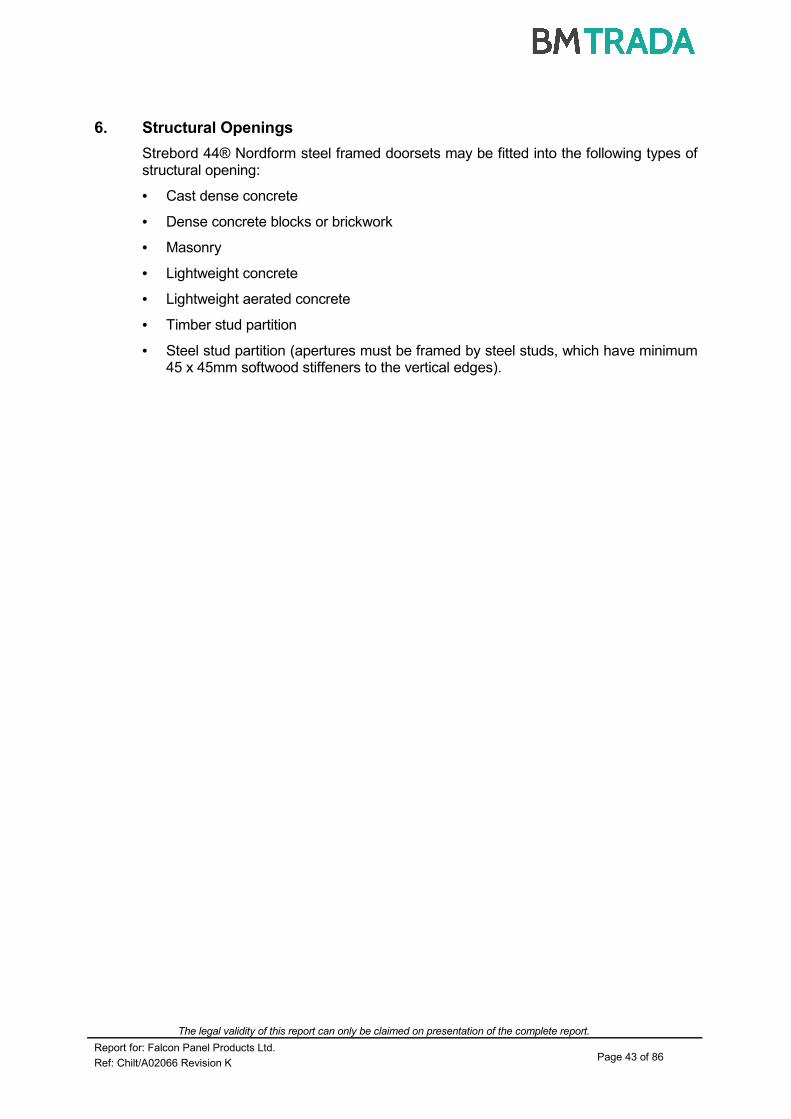
6. Structural Openings
Strebord 44® Nordform steel framed doorsets may be fitted into the following types of structural opening:
• Cast dense concrete
• Dense concrete blocks or brickwork
• Masonry
• Lightweight concrete
• Lightweight aerated concrete
• Timber stud partition
• Steel stud partition (apertures must be framed by steel studs, which have minimum 45 x 45mm softwood stiffeners to the vertical edges).
The legal validity of this report can only be claimed on presentation of the complete report.
Report for: Falcon Panel Products Ltd. Page 44 of 86
Ref: Chilt/A02066 Revision K
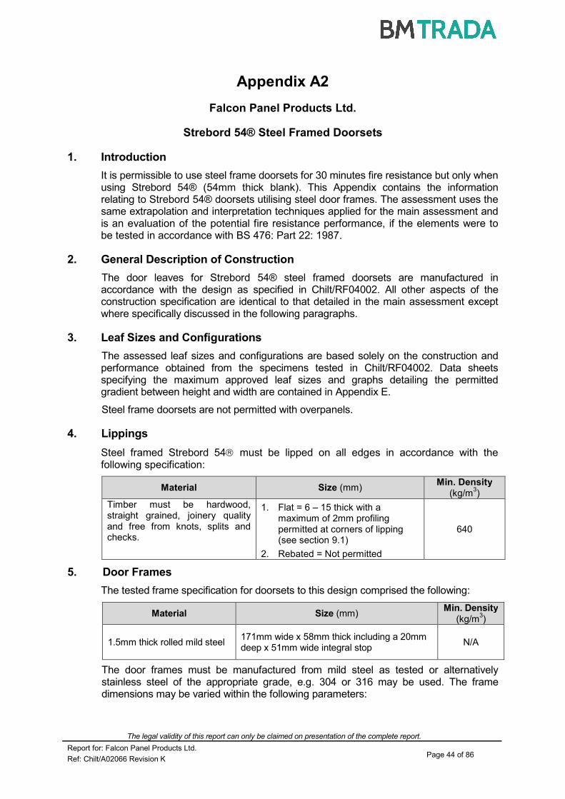
Appendix A2
Falcon Panel Products Ltd.
Strebord 54® Steel Framed Doorsets
1. Introduction
It is permissible to use steel frame doorsets for 30 minutes fire resistance but only when using Strebord 54® (54mm thick blank). This Appendix contains the information relating to Strebord 54® doorsets utilising steel door frames. The assessment uses the same extrapolation and interpretation techniques applied for the main assessment and is an evaluation of the potential fire resistance performance, if the elements were to be tested in accordance with BS 476: Part 22: 1987.
2. General Description of Construction
The door leaves for Strebord 54® steel framed doorsets are manufactured in accordance with the design as specified in Chilt/RF04002. All other aspects of the construction specification are identical to that detailed in the main assessment except where specifically discussed in the following paragraphs.
3. Leaf Sizes and Configurations
The assessed leaf sizes and configurations are based solely on the construction and performance obtained from the specimens tested in Chilt/RF04002. Data sheets specifying the maximum approved leaf sizes and graphs detailing the permitted gradient between height and width are contained in Appendix E.
Steel frame doorsets are not permitted with overpanels.
4. Lippings
Steel framed Strebord 54 must be lipped on all edges in accordance with the following specification:
Material Size (mm) Min. Density
(kg/m3)
Timber must be hardwood, straight grained, joinery quality and free from knots, splits and checks.
1. Flat = 6 – 15 thick with a maximum of 2mm profiling permitted at corners of lipping (see section 9.1)
2. Rebated = Not permitted
640
5. Door Frames
The tested frame specification for doorsets to this design comprised the following:
Material Size (mm) Min. Density
(kg/m3)
1.5mm thick rolled mild steel 171mm wide x 58mm thick including a 20mm deep x 51mm wide integral stop
N/A
The door frames must be manufactured from mild steel as tested or alternatively stainless steel of the appropriate grade, e.g. 304 or 316 may be used. The frame dimensions may be varied within the following parameters:

The legal validity of this report can only be claimed on presentation of the complete report.
Report for: Falcon Panel Products Ltd. Page 45 of 86
Ref: Chilt/A02066 Revision K
Z
Y
X
X: + or - 30% Y: + or - 50% (providing the frame reveal dimensions are maintained)
Z: + 100 % and −−−− 0%
The frame may be hollow or back filled with mortar or concrete. Plasterboard, mineral fibre, glass fibre and ceramic wool must not be used. Appendix E details the leaf size ranges and intumescent seal specifications for steel frame constructions.
6. Fixings
Fixings must be of the appropriate type and length for the structural opening medium and must include a minimum of 1 fixing for no more than 600mm of vertical edge, with a fixing no more than 350mm from the top and bottom corners. Two fixings are required to the frame head.
7. Sealing to Structural Opening
Gaps between doorframes and structural openings must be protected with proprietary materials that have been successfully tested for this application.
8. Structural Openings
Strebord 54® steel framed doorsets may be fitted into the following types of structural opening:
• Cast dense concrete
• Dense concrete blocks or brickwork
• Masonry
• Lightweight concrete
• Lightweight aerated concrete
• Timber stud partition
• Steel stud partition (apertures must be framed by steel studs, which have a minimum of 45 x 45mm softwood stiffeners to the vertical edges).

The legal validity of this report can only be claimed on presentation of the complete report.
Report for: Falcon Panel Products Ltd. Page 46 of 86
Ref: Chilt/A02066 Revision K
Appendix B
Performance Data
Primary Data
Report No. Configuration Leaf Size
(mm) Test Standard
Performance (mins)
RF98048 ULSADD
2100
902
44
BS 476: Pt 22: 1987 42
RF98137 ULSADD
2100
902
44
BS 476: Pt 22: 1987 32 (glazing)
41
RF99050 ULSADD + OP
2100
900
44
BS 476: Pt 22: 1987 36
RF01030 ULSADD
2100
902
44
BS 476: Pt 22: 1987 32
RF02109 A: ULSASD
B: LSASD
A: 2136
936
44
B: 2700
1072
44
BS 476: Pt 22: 1987 A: 34
B: 35
Warres 144699 ULSADD
2100
901
44
BS 476: Pt 22: 1987 38
Warres 141445 ULSADD
2100
902
44
BS 476: Pt 22: 1987 40
Chilt/RF03114 (Strebord 38+)
A: ULSASD
B: ULSASD
A: 2100
896
46
B: 2086
885
46
BS 476: Pt 22: 1987 A: 61
B: 57
Chilt/A05134 (Tall doors)
A: ULSASD
B: ULSASD
A: 2040
915
44
B: 2800
915
44
BS 476: Pt 22: 1987 A: 37
B: 38
RF11161
(70 x 25mm
softwood door frames)
ULSADD
2135 915
35
BS 476: Pt 20/22: 1987
32
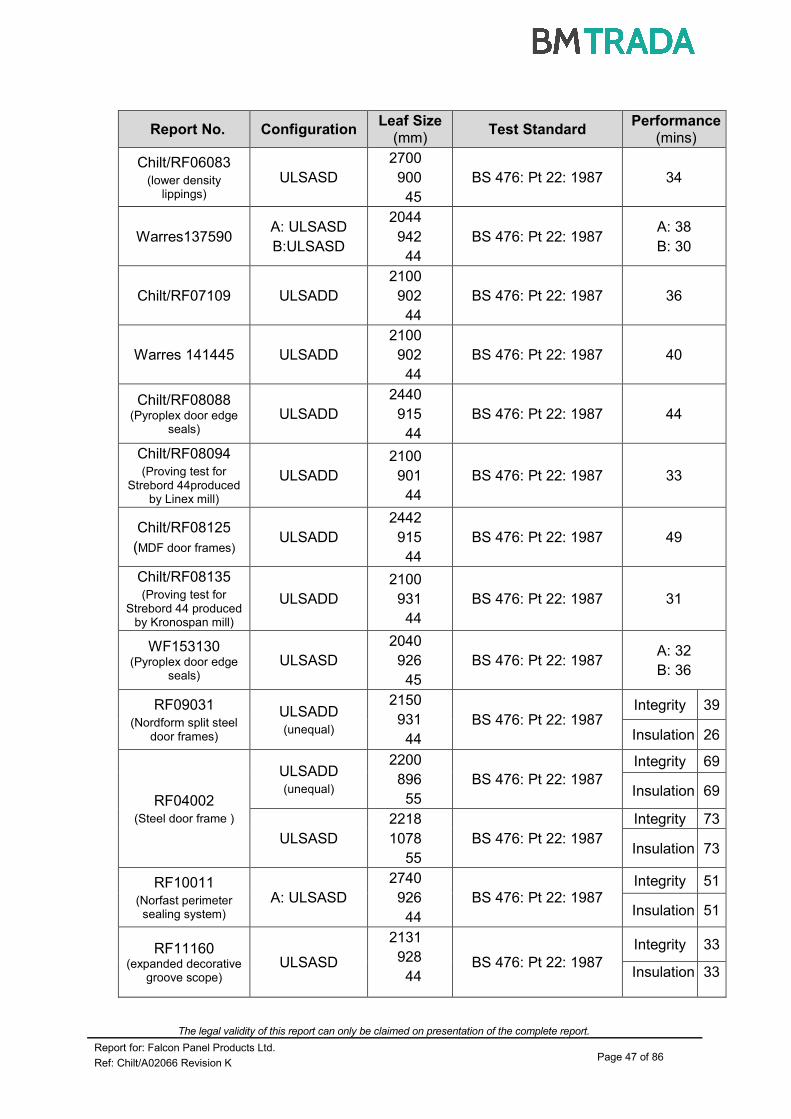
The legal validity of this report can only be claimed on presentation of the complete report.
Report for: Falcon Panel Products Ltd. Page 47 of 86
Ref: Chilt/A02066 Revision K
Report No. Configuration Leaf Size
(mm) Test Standard
Performance (mins)
Chilt/RF06083 (lower density
lippings)
ULSASD
2700
900
45
BS 476: Pt 22: 1987 34
Warres137590 A: ULSASD
B:ULSASD
2044
942
44
BS 476: Pt 22: 1987 A: 38
B: 30
Chilt/RF07109 ULSADD
2100
902
44
BS 476: Pt 22: 1987 36
Warres 141445 ULSADD
2100
902
44
BS 476: Pt 22: 1987 40
Chilt/RF08088 (Pyroplex door edge
seals) ULSADD
2440
915
44
BS 476: Pt 22: 1987 44
Chilt/RF08094 (Proving test for
Strebord 44produced by Linex mill)
ULSADD
2100
901
44
BS 476: Pt 22: 1987 33
Chilt/RF08125
(MDF door frames) ULSADD
2442
915
44
BS 476: Pt 22: 1987 49
Chilt/RF08135 (Proving test for
Strebord 44 produced by Kronospan mill)
ULSADD
2100
931
44
BS 476: Pt 22: 1987 31
WF153130 (Pyroplex door edge
seals) ULSASD
2040
926
45
BS 476: Pt 22: 1987 A: 32
B: 36
RF09031 (Nordform split steel
door frames)
ULSADD (unequal)
2150
931
44
BS 476: Pt 22: 1987 Integrity 39
Insulation 26
RF04002 (Steel door frame )
ULSADD (unequal)
2200
896
55
BS 476: Pt 22: 1987
Integrity 69
Insulation 69
ULSASD
2218
1078
55
BS 476: Pt 22: 1987
Integrity 73
Insulation 73
RF10011 (Norfast perimeter
sealing system) A: ULSASD
2740
926
44
BS 476: Pt 22: 1987 Integrity 51
Insulation 51
RF11160 (expanded decorative
groove scope) ULSASD
2131
928
44 BS 476: Pt 22: 1987
Integrity 33
Insulation 33
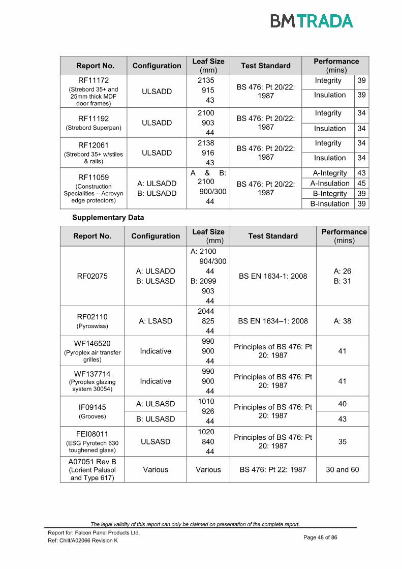
The legal validity of this report can only be claimed on presentation of the complete report.
Report for: Falcon Panel Products Ltd. Page 48 of 86
Ref: Chilt/A02066 Revision K
Report No. Configuration Leaf Size
(mm) Test Standard
Performance (mins)
RF11172 (Strebord 35+ and 25mm thick MDF
door frames)
ULSADD
2135
915
43
BS 476: Pt 20/22: 1987
Integrity 39
Insulation 39
RF11192 (Strebord Superpan)
ULSADD
2100
903
44
BS 476: Pt 20/22: 1987
Integrity 34
Insulation 34
RF12061 (Strebord 35+ w/stiles
& rails) ULSADD
2138
916
43
BS 476: Pt 20/22: 1987
Integrity 34
Insulation 34
RF11059 (Construction
Specialities – Acrovyn edge protectors)
A: ULSADD
B: ULSADD
A & B: 2100
900/300
44
BS 476: Pt 20/22: 1987
A-Integrity 43
A-Insulation 45
B-Integrity 39
B-Insulation 39
Supplementary Data
Report No. Configuration Leaf Size
(mm) Test Standard
Performance (mins)
RF02075 A: ULSADD
B: ULSASD
A: 2100
904/300
44
B: 2099
903
44
BS EN 1634-1: 2008 A: 26
B: 31
RF02110 (Pyroswiss)
A: LSASD
2044
825
44
BS EN 1634–1: 2008 A: 38
WF146520 (Pyroplex air transfer
grilles)
Indicative
990
900
44
Principles of BS 476: Pt 20: 1987
41
WF137714 (Pyroplex glazing
system 30054) Indicative
990
900
44
Principles of BS 476: Pt 20: 1987
41
IF09145 (Grooves)
A: ULSASD 1010
926
44
Principles of BS 476: Pt 20: 1987
40
B: ULSASD 43
FEI08011 (ESG Pyrotech 630 toughened glass)
ULSASD
1020
840
44
Principles of BS 476: Pt 20: 1987
35
A07051 Rev B (Lorient Palusol and Type 617)
Various Various BS 476: Pt 22: 1987 30 and 60

The legal validity of this report can only be claimed on presentation of the complete report.
Report for: Falcon Panel Products Ltd. Page 49 of 86
Ref: Chilt/A02066 Revision K
Report No. Configuration Leaf Size
(mm) Test Standard
Performance
(mins)
IF12011
(Norsound Vision – softwood beads and square beads with non-insulating
glass)
Swinging sample
(ULSASD)
1052
1020
44
Temperature and pressure conditions of BS 476: Part 20: 1987 and principles of BS 476: Part 22:
1987
Integrity: 38
RF11177
(Pilkington Pyroclear)
ULSASD in a glazed screen
2070
930
44
BS EN 1634-1: 2008
Integrity: 32
IF13014 (Norsound
hardware gaskets)
A: LSADD
B: LSADD
A: 1268
279
44
B: 1262
279
54
BS 476: Part 20/22: 1987
A: 48
B: 69
IF13061 (Norsound
Universal glazing system)
ULSASD
1052
900
64
Temperature and pressure conditions of BS 476: Part 20: 1987 and principles of BS 476: Part 22:
1987
Integrity: 96
Notes:
1. Test RF02075 is used to justify 8mm thick lippings. Although the double leaf failed at 26 minutes, the result of the single leaf and the known relative severity of the European test standard compared to the BS test standard, permits us to assess the thinner lippings across the range of assessed doorsets.
2. The Pyroplex air transfer grilles in test WF146520 were tested under positive pressure for 30 minutes fire resistance in a section of 44mm thick particleboard door. It has been deemed acceptable for the same products to be fitted at positive and negative pressure locations based on the comparative data generated for 60 minutes fire resistance contained in test WF148053.
3. The doorsets tested in IF09145 were positioned in the furnace to simulate both the top and bottom half of a standard size doorset.
4. The tested specification of the Norfast sealing system is contained in test report RF10011 and is held in confidence. The tested direction of the seal, with respect to fire exposure, was asymmetric. However, based on the performance of the seal in RF10011 and the leaf size scope given in the relevant data sheet in Appendix E, it has been assessed as being acceptable for use with doorsets that open in either direction.

The legal validity of this report can only be claimed on presentation of the complete report.
Report for: Falcon Panel Products Ltd. Page 50 of 86
Ref: Chilt/A02066 Revision K
Appendix C
Revisions & Amendments
Rev. CIFL Ref. Date Description
A 02251 1/03 New test data incorporated (RF02109) to increase leaf dimensions and glazed area.
B 03052 3/03 Inclusion of data from test RF03018.
C 05080 4/05 Inclusion of data from test Warres 144699 and Warres 141445.
D 06067 5/06
Inclusion of data from Chilt/RF05134 and Chilt/RF06067. PVA gluelines, MDF frames, leaf size increases, alternative perimeter intumescent seals and frame density amendments made.
E 06083 10/06 Inclusion of data from Chilt/RF06083 to include lower density lippings.
F 06175F 1/07 Changes to include Pyroswiss glass, ventilation grilles, Pyroplex seals and more flexibility in the glazing location.
G 08040 5/08
Update into new format and revalidation for a further 5 years. Inclusion of data from RF07109, Warres 141445. Data sheet revised in terms of intumescent seal type and size.
H 08204 10/08 Revalidation for a further 5 years and inclusion of data from RF08088, RF08094, RF08125, RF08135, WF153130, WF146520 and WF137714 (see appendix A for details).
I 09232 15/12
Addition of Nordform steel frame data contained in RF09031, grooves based on IF09145, Pyrotech 630 glazing system based on IF08011, Norfast perimeter seal tested in RF10011 and re-instatement of Type 617 seals and additional glass types.
J 12120 07/12
Addition of Strebord 35+, Strebord 38+ and Strebord Superpan designs, an expansion of the decorative groove scope within the facing section of this assessment, reduction in density and dimensions of the door frames and inclusion of identification discs/signage based on data from RF03114, RF11160, RF11172, RF11192, RF12061.
K 13155 07/13
Addition of CS Group edge protectors and post-formed Acrovyn based on RF11059. Addition of Pilkington Pyroclear based on RF11177. Included the option to fit the Safehinge™ product. Increased the maximum leaf dimensions based on the Strebord 44 panelled design. Addition of Norsound hardware gaskets based on IF13014. Addition of Norsound glazing systems IF12011 and IF13061.

The legal validity of this report can only be claimed on presentation of the complete report.
Report for: Falcon Panel Products Ltd. Page 51 of 86
Ref: Chilt/A02066 Revision K
Appendix D
Proprietary 30 Minute Glazing Systems
10-15°
515
Assessed glassSystem 36 gasket
System 36
Lorient Polyproducts Ltd
40mm pins
or screws
10-15°
515
Assessed glassSystem FF1
System FF1
Lorient Polyproducts Ltd
40mm pins
or screws
10-15°
515
Assessed glassSystem 36 Plus gasket
System 36 Plus
Lorient Polyproducts Ltd
40mm pins
or screws
10-15°
515
Assessed glassHodgsons
Firestrip 30
Firestrip 30
Hodgsons Sealants Ltd
40mm pins
or screws

The legal validity of this report can only be claimed on presentation of the complete report.
Report for: Falcon Panel Products Ltd. Page 52 of 86
Ref: Chilt/A02066 Revision K
10-15°
515
Assessed glass10mm x 3mm
500SA
Pyroglaze 30
Mann McGowan Ltd
40mm pins
or screws
10-15°
515
Assessed glassNorglaze 30
Norglaze 30
Norseal Ltd
40mm pins
or screws
40mm pins
or screws
Therm-A-Strip
10-15°
Assessed glass10mm x 2 mm
Therm-A-Strip
Intumescent Seals Ltd
0.5 1.5
Fireglaze
10-15°
Assessed glass
5
11mm x 2 mm
Fireglaze
Sealmaster Ltd
40mm pins
or screws
15
4
0.5 1.5
5 15
4
40mm pins
or screws
10-15°
515
Assessed glassGlazing channel
ref: R8193
Pyroplex Ltd
Norsound Vision Norsound Ltd
Norsound Vision 30

The legal validity of this report can only be claimed on presentation of the complete report.
Report for: Falcon Panel Products Ltd. Page 53 of 86
Ref: Chilt/A02066 Revision K
Tested Glazing System for ESG Pyrotech 630 Glass
Therm-A-Strip
12° Chamfer
6mm ESG
10mm x 2 mm
50mm pins
154
4
Pyrotech 630
11mm wide
Aluminium foil
edge protection
10-15°
515
Assessed glassSystem 30049
10-15°
515
Assessed glassGlazing channel
ref: 30054
Pyroplex Ltd
50mm pins
or 40mm screws
50mm pins
or 40mm screws
Pyroplex Ltd

The legal validity of this report can only be claimed on presentation of the complete report.
Report for: Falcon Panel Products Ltd. Page 54 of 86
Ref: Chilt/A02066 Revision K
Splayed Flush Bead Option
A splayed flush bead may be used with approved glazing systems subject to the following:
1. The aperture must be lined using ≥6mm thickness of hardwood of ≥640kg/m3 density.
2. The bead must be ≥ to 15mm high, with a 10-150 chamfer.
3. A rebate not exceeding 2 x 2mm may be used to the bead or lining to accommodate door thickness tolerances.
Diagram Depicts Assessed System
Assessed Square Glazing Bead Profiles
(The following square bead profiled may be used as an alternative to the splayed beads detailed above - refer to section 6 for glazing system and glass restrictions.)
6mm hardwood lining
Glazing system (see section 6.1)
10-150 chamfer
50mm pins or 40mm screws
3
3
15
5
5
Suited to glass thickness
15
To finish flush with the leaf face
15
To finish flush with the leaf face

The legal validity of this report can only be claimed on presentation of the complete report.
Report for: Falcon Panel Products Ltd. Page 55 of 86
Ref: Chilt/A02066 Revision K
Appendix E
Data Sheets for:
Falcon Panel Products Ltd.
Strebord 30 Minutes Fire Resistant Doorsets

The legal validity of this report can only be claimed on presentation of the complete report.
Report for: Falcon Panel Products Ltd. Page 56 of 86
Ref: Chilt/A02066 Revision K
Maximum Door Leaf Size
2100
2150
2200
2250
2300
2350
2400
2450
900920940960980100010201040
Width (mm)
He
igh
t (m
m)
LSASD ULSASD & DASD
Falcon Panel Products – Strebord 35+/38+ - With Softwood Stiles & Rails Only
Latched & Unlatched, Single & Double Acting, Single Doorsets
Leaf Sizes
Configuration Height (mm) Width (mm)
ULSASD & DASD
From: To:
2138 x 1020
2366 x 916
LSASD From:
To:
2138 x 1045
2416 x 916
Maximum Overpanel Height (mm) Transomed 2000
Glazing Maximum Glazed Area 1.9m
2 - see section 6 for restrictions
Approved Systems See section 6 and Appendix D
Frame Specification
Material Softwood Hardwood MDF
Min. Density (kg/m3) 450 450 700
Min. Section (mm) 70x25 70x25 70x25
Max. Leaf Dimensions All All All
Intumescent Materials: Mann McGowan Ltd. Pyrostrip 100P
Head: 1No. 10x4mm fitted centrally in the leaf edge of frame reveal. Jambs: 1No. 10x4mm fitted centrally in the leaf edge or frame reveal. Hardware Protection: See section 11.

The legal validity of this report can only be claimed on presentation of the complete report.
Report for: Falcon Panel Products Ltd. Page 57 of 86
Ref: Chilt/A02066 Revision K
Maximum Door Leaf Size
2100
2150
2200
2250
2300
2350
9009109209309409509609709809901000Width (mm)
He
igh
t (m
m)
LSADD ULSADD & DADD
Falcon Panel Products – Strebord 35+/38+ - With Softwood Stiles & Rails Only
Latched & Unlatched, Single & Double Acting, Double Doorsets
Leaf Sizes
Configuration Height (mm) Width (mm)
ULSADD & DADD
From: To:
2138 x 970
2266 x 916
LSADD From:
To:
2138 x 995
2316 x 916
Maximum Overpanel Height (mm) Transomed 1500
Glazing Maximum Glazed Area 1.9m
2 - see section 6 for restrictions
Approved Systems See section 6 and Appendix D
Frame Specification
Material Softwood Hardwood MDF
Min. Density (kg/m3) 450 450 700
Min. Section (mm) 70x25 70x25 70x25
Max. Leaf Dimensions All All All
Intumescent Materials: Mann McGowan Ltd. Pyrostrip 100P
Head: Square: 10x4mm exposed and centrally fitted in the leaf or frame head.
Meeting Edges: Square: 2No. 10x4mm spaced 10mm apart and centrally fitted in one leaf edge. Jambs & Overpanel: 1No. 10x4mm exposed and centrally fitted in the leaf or frame. Hardware Protection: See section 11.

The legal validity of this report can only be claimed on presentation of the complete report.
Report for: Falcon Panel Products Ltd. Page 58 of 86
Ref: Chilt/A02066 Revision K
Maximum Door Leaf Size
2700
2710
2720
2730
2740
2750
2760
2770
2780
2790
2800
900910920930940950960Width (mm)
He
ight
(mm
)
LSASD ULSASD & DASD
Falcon Panel Products – Strebord 44®
Latched & Unlatched, Single & Double Acting, Single Doorsets
Leaf Sizes
Configuration Height (mm) Width (mm)
LSASD From:
To:
2740 x 951
2790 x 926
ULSASD & DASD
From: To:
2740 x 926
2740 x 926
Maximum Overpanel Height (mm) Transomed 2000
Glazing Maximum Glazed Area 1.9m
2 - see section 6 for restrictions
Approved Systems See section 6 and Appendix D
Frame Specification
Material Softwood Hardwood MDF
Min. Density (kg/m3) 450 450 700
Min. Section (mm) 70x25 70x25 70x25
Max. Leaf Dimensions All All All
Intumescent Materials: Norfast Perimeter Seal
Head: 1No. Norfast seal surface fixed in the frame reveal butted up against the upstand of the door stop.
Jambs: 1No. Norfast seal surface fixed in the frame reveal butted up against the upstand of the door stop. Overpanel: 1No. 10x4mm intumescent seal (see approved edge seal types in section 11) centrally fitted in the edges of the
overpanel or frame reveal. Hardware Protection: See section 11.
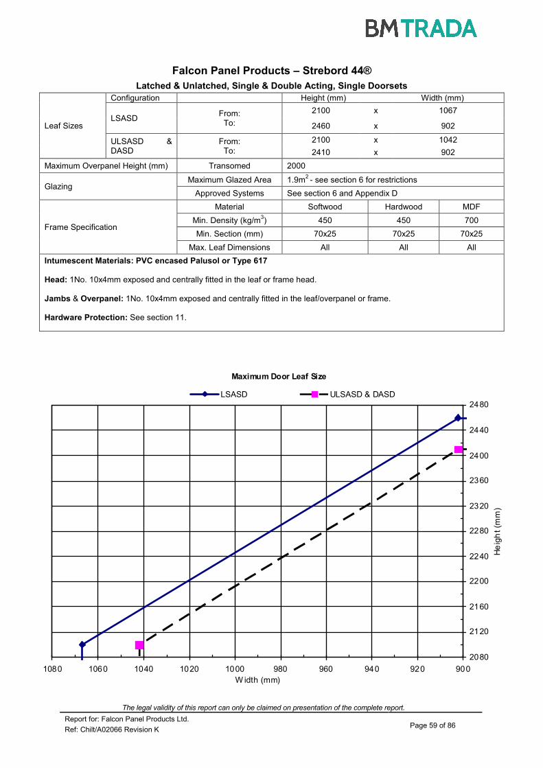
The legal validity of this report can only be claimed on presentation of the complete report.
Report for: Falcon Panel Products Ltd. Page 59 of 86
Ref: Chilt/A02066 Revision K
Maximum Door Leaf Size
2080
2120
2160
2200
2240
2280
2320
2360
2400
2440
2480
90092094096098010001020104010601080
W idth (mm)
He
igh
t (m
m)
LSASD ULSASD & DASD
Falcon Panel Products – Strebord 44®
Latched & Unlatched, Single & Double Acting, Single Doorsets
Leaf Sizes
Configuration Height (mm) Width (mm)
LSASD From:
To:
2100 x 1067
2460 x 902
ULSASD & DASD
From: To:
2100 x 1042
2410 x 902
Maximum Overpanel Height (mm) Transomed 2000
Glazing Maximum Glazed Area 1.9m
2 - see section 6 for restrictions
Approved Systems See section 6 and Appendix D
Frame Specification
Material Softwood Hardwood MDF
Min. Density (kg/m3) 450 450 700
Min. Section (mm) 70x25 70x25 70x25
Max. Leaf Dimensions All All All
Intumescent Materials: PVC encased Palusol or Type 617
Head: 1No. 10x4mm exposed and centrally fitted in the leaf or frame head.
Jambs & Overpanel: 1No. 10x4mm exposed and centrally fitted in the leaf/overpanel or frame. Hardware Protection: See section 11.

The legal validity of this report can only be claimed on presentation of the complete report.
Report for: Falcon Panel Products Ltd. Page 60 of 86
Ref: Chilt/A02066 Revision K
Maximum Door Leaf Size
2020
2040
2060
2080
2100
900910920930940950960Width (mm)
Heig
ht
(mm
)
LSASD ULSASD
Falcon Panel Products – Strebord 44®
Latched & Unlatched, Single & Double Acting, Single Doorsets
Leaf Sizes
Configuration Height (mm) Width (mm)
LSASD From:
To:
2040 x 951
2090 x 926
ULSASD From:
To:
2040 x 926
2040 x 926
Maximum Overpanel Height (mm) Transomed 2000
Glazing Maximum Glazed Area 1.9m
2 - see section 6 for restrictions
Approved Systems See section 6 and Appendix D
Frame Specification
Material Softwood Hardwood MDF
Min. Density (kg/m3) 450 450 700
Min. Section (mm) 70x25 70x25 70x25
Max. Leaf Dimensions All All All
Intumescent Materials: Pyroplex
Head: 1No. 10x4mm exposed and centrally fitted in the leaf or frame head.
Jambs & Overpanel: 1No. 10x4mm exposed and centrally fitted in the leaf/overpanel or frame. Hardware Protection: See section 11.

The legal validity of this report can only be claimed on presentation of the complete report.
Report for: Falcon Panel Products Ltd. Page 61 of 86
Ref: Chilt/A02066 Revision K
Maximum Door Leaf Size
2380
2400
2420
2440
2460
2480
2500
2520
2540
2560
2580
2600
2620
9209309409509609709809901000101010201030
Width (mm)
Heig
ht
(mm
)
LSASD & DASD & ULSASD
Falcon Panel Products – Strebord 44®
Latched & Unlatched, Single & Double Acting, Single Doorsets
Leaf Sizes
Configuration Height (mm) Width (mm)
LSASD & DASD & ULSASD
From: To:
2400 x 1026
2600 x 926
Maximum Overpanel Height (mm) Transomed 2000
Glazing Maximum Glazed Area 1.9m
2 - see section 6 for restrictions
Approved Systems See section 6 and Appendix D
Frame Specification
Material Softwood Hardwood MDF
Min. Density (kg/m3) 450 450 700
Min. Section (mm) 70x25 70x25 70x25
Max. Leaf Dimensions All All All
Intumescent Materials: PVC encased Type 617
Head: 1No. 15x4mm exposed and centrally fitted in the leaf or frame head.
Jambs & Overpanel: 1No. 15x4mm exposed and centrally fitted in the leaf or frame head. Hardware Protection: See section 11.

The legal validity of this report can only be claimed on presentation of the complete report.
Report for: Falcon Panel Products Ltd. Page 62 of 86
Ref: Chilt/A02066 Revision K
Maximum Door Leaf Size
2050
2150
2250
2350
2450
2550
2650
2750
2850
2950
900100011001200Width (mm)
He
igh
t (m
m)
LSASD ULSASD & DASD
Falcon Panel Products – Strebord 44®
Latched & Unlatched, Single & Double Acting, Single Doorsets
Leaf Sizes
Configuration Height (mm) Width (mm)
LSASD From:
To:
2700 x 1161
2925 x 1072
ULSASD & DASD
From: To:
2100 x 1140
2620 x 915
Maximum Overpanel Height (mm) Transomed 2000
Glazing Maximum Glazed Area 1.9m
2 - see section 6 for restrictions
Approved Systems See section 6 and Appendix D
Frame Specification
Material Softwood Hardwood MDF
Min. Density (kg/m3) 450 450 700
Min. Section (mm) 70x25 70x25 70x25
Max. Leaf Dimensions All All All
Intumescent Materials: PVC encased Palusol 100 or Type 617
Head: 1No. 15x4mm exposed and centrally fitted in the leaf or frame head.
Jambs & Overpanel: 1No. 15x4mm exposed and centrally fitted in the leaf or frame. Hardware Protection: See section 11

The legal validity of this report can only be claimed on presentation of the complete report.
Report for: Falcon Panel Products Ltd. Page 63 of 86
Ref: Chilt/A02066 Revision K
Falcon Panel Products - Strebord 44 Latched & Unlatched, Single & Double Acting, Single Leaf Doorsets
Configuration Height (mm) Width (mm)
Leaf Sizes
LSASD From:
To:
2135 x 1310
2979 x 932
ULSASD & DASD From:
To:
2135 x 1285
2929 x 932
Maximum Overpanel Height (mm) Transomed 2000
Glazing Maximum Glazed Area 1.9m
2 – see section 6 for restrictions
Approved Systems See section 6 and Appendix D
Frame Specification
Material Softwood Hardwood MDF
Min. Density (kg/m3) 465 465 750
Min. Section (mm) 70x25 70x25 70x25
Max. Leaf Dimensions All All All
Intumescent Materials: Pyroplex Rigid Box Seal PVC Encased Graphite
Head: 1No. 15x4mm strip exposed and fitted centrally in the leaf edge or frame reveal. Increase seal to 20x4mm on doorsets
over 2300mm high.
Jambs: 1No. 15x4mm strip exposed and fitted centrally in the leaf edge or frame reveal. Increase seal to 20x4mm on
doorsets over 1075mm wide.
Hardware Protection: See section 11.
Note: Intumescent protection is required under the hinge blades on both leaf and frame on door leaves over 2440mm high.
Maximum Door Leaf Size
2100
2200
2300
2400
2500
2600
2700
2800
2900
3000
920960100010401080112011601200124012801320
Width (mm)
Heig
ht (m
m)
LSASD ULSASD + DASD

The legal validity of this report can only be claimed on presentation of the complete report.
Report for: Falcon Panel Products Ltd. Page 64 of 86
Ref: Chilt/A02066 Revision K
Maximum Door Leaf Size
2400
2500
2600
2700
2800
900940980102010601100
Width (mm)
He
igh
t (m
m)
LSASD ULSASD & DASD
Falcon Panel Products – Strebord 44®
Latched & Unlatched, Single & Double Acting, Single Doorsets
Leaf Sizes
Configuration Height (mm) Width (mm)
LSASD From:
To:
2440 x 1100
2800 x 915
ULSASD & DASD
From: To:
2440 x 1075
2750 x 915
Maximum Overpanel Height (mm) Transomed 2000
Glazing Maximum Glazed Area 1.9m
2 - see section 6 for restrictions
Approved Systems See section 6 and Appendix D
Frame Specification
Material Softwood Hardwood MDF
Min. Density (kg/m3) 450 450 700
Min. Section (mm) 70x25 70x25 70x25
Max. Leaf Dimensions All All All
Intumescent Materials: Pyroplex
Head: 1No. 15x4mm exposed and centrally fitted in the leaf or frame head.
Jambs & Overpanel: 1No. 15x4mm exposed and centrally fitted in the leaf or frame. Hardware Protection: See section 11.

The legal validity of this report can only be claimed on presentation of the complete report.
Report for: Falcon Panel Products Ltd. Page 65 of 86
Ref: Chilt/A02066 Revision K
Maximum Door Leaf Size
2700
2800
2900
3000
3100
3200
10801100112011401160118012001220
Width (mm)
Heig
ht
(mm
)
LSASD ULSASD & DASD
Falcon Panel Products – Strebord 44®
Latched & Unlatched, Single & Double Acting, Single Doorsets
Leaf Sizes
Configuration Height (mm) Width (mm)
LSASD From:
To:
2800 x 1203
3159 x 1100
ULSASD & DASD
From: To:
2800 x 1178
3109 x 1100
Maximum Overpanel Height (mm) Transomed 2000
Glazing Maximum Glazed Area 1.9m
2 - see section 6 for restrictions
Approved Systems See section 6 and Appendix D
Frame Specification
Material Softwood Hardwood MDF
Min. Density (kg/m3) 450 450 700
Min. Section (mm) 70x25 70x25 70x25
Max. Leaf Dimensions All All All
Intumescent Materials: Pyroplex
Head: 1No. 20x4mm exposed and centrally fitted in the leaf or frame head.
Jambs & Overpanel: 1No. 20x4mm exposed and centrally fitted in the leaf or frame. Hardware Protection: See section 11.

The legal validity of this report can only be claimed on presentation of the complete report.
Report for: Falcon Panel Products Ltd. Page 66 of 86
Ref: Chilt/A02066 Revision K
Maximum Door Leaf Size
2780
2800
2820
2840
2860
2880
2900
2920
2940
2960
2980
3000
3020
910920930940950960970
Width (mm)
Heig
ht
(mm
)
LSASD ULSASD & DASD
Falcon Panel Products – Strebord 44®
Latched & Unlatched, Single & Double Acting, Single Doorsets
Leaf Sizes
Configuration Height (mm) Width (mm)
LSASD From:
To:
2800 x 965
3000 x 915
ULSASD & DASD
From: To:
2800 x 940
3000 x 915
Maximum Overpanel Height (mm) Transomed 2000
Glazing Maximum Glazed Area 1.9m
2 - see section 6 for restrictions
Approved Systems See section 6 and Appendix D
Frame Specification
Material Softwood Hardwood MDF
Min. Density (kg/m3) 450 450 700
Min. Section (mm) 70x25 70x25 70x25
Max. Leaf Dimensions All All All
Intumescent Materials: PVC encased Palusol 100 or Type 617
Head: 20x4mm exposed and centrally fitted in the leaf or frame head.
Jambs & Overpanel: 20x4mm exposed and centrally fitted in the leaf or frame. Hardware Protection: See section 11.
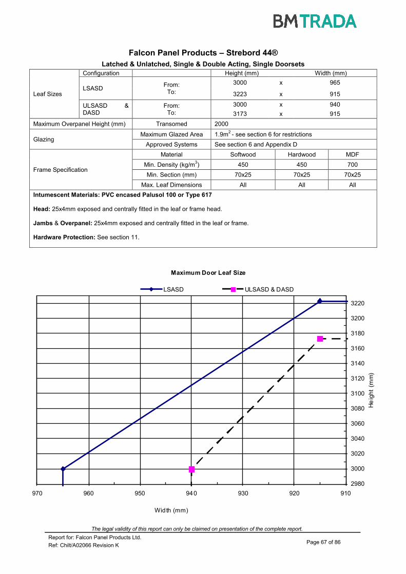
The legal validity of this report can only be claimed on presentation of the complete report.
Report for: Falcon Panel Products Ltd. Page 67 of 86
Ref: Chilt/A02066 Revision K
Maximum Door Leaf Size
2980
3000
3020
3040
3060
3080
3100
3120
3140
3160
3180
3200
3220
910920930940950960970
Width (mm)
He
igh
t (m
m)
LSASD ULSASD & DASD
Falcon Panel Products – Strebord 44®
Latched & Unlatched, Single & Double Acting, Single Doorsets
Leaf Sizes
Configuration Height (mm) Width (mm)
LSASD From:
To:
3000 x 965
3223 x 915
ULSASD & DASD
From: To:
3000 x 940
3173 x 915
Maximum Overpanel Height (mm) Transomed 2000
Glazing Maximum Glazed Area 1.9m
2 - see section 6 for restrictions
Approved Systems See section 6 and Appendix D
Frame Specification
Material Softwood Hardwood MDF
Min. Density (kg/m3) 450 450 700
Min. Section (mm) 70x25 70x25 70x25
Max. Leaf Dimensions All All All
Intumescent Materials: PVC encased Palusol 100 or Type 617
Head: 25x4mm exposed and centrally fitted in the leaf or frame head.
Jambs & Overpanel: 25x4mm exposed and centrally fitted in the leaf or frame. Hardware Protection: See section 11.

The legal validity of this report can only be claimed on presentation of the complete report.
Report for: Falcon Panel Products Ltd. Page 68 of 86
Ref: Chilt/A02066 Revision K
Maximum Door Leaf Size
2050
2070
2090
2110
2130
2150
800820840860880900920
Width (mm)
Heig
ht
(mm
)
LSASD & DASD & ULSASD
Falcon Panel Products – Strebord 44®
Latched & Unlatched, Single & Double Acting, Single Doorsets
Leaf Sizes
Configuration Height (mm) Width (mm)
LSASD & DASD & ULSASD
From: To:
2134 x 915
2134 x 915
Maximum Overpanel Height (mm) Transomed 2000
Glazing Maximum Glazed Area 1.9m
2 - see section 6 for restrictions
Approved Systems See section 6 and Appendix D
Frame Specification
Material Softwood Hardwood MDF
Min. Density (kg/m3) 450 450 700
Min. Section (mm) 70x25 70x25 70x25
Max. Leaf Dimensions All All All
Intumescent Materials: Therm-A-Seal
Head: 1No. 15x4mm exposed and centrally fitted in the leaf or frame head.
Jambs & Overpanel: 1No. 15x4mm exposed and centrally fitted in the leaf/overpanel or frame. Hardware Protection: See section 11.

The legal validity of this report can only be claimed on presentation of the complete report.
Report for: Falcon Panel Products Ltd. Page 69 of 86
Ref: Chilt/A02066 Revision K
Maximum Door Leaf Size
2100
2110
2120
2130
2140
900905910915920
Width (mm)
Heig
ht
(mm
)
LSASD+OP & DASD+OP & ULSASD+OP
Falcon Panel Products – Strebord 44®
Latched & Unlatched, Single & Double Acting, Single Doorsets + Overpanel
Leaf Sizes
Configuration Height (mm) Width (mm)
LSASD+OP & DASD+OP & ULSASD+OP
From: To:
2134 x 915
2134 x 915
Maximum Overpanel Height (mm) 2000
Glazing Maximum Glazed Area 1.9m
2 - see section 6 for restrictions
Approved Systems See section 6 and Appendix D
Frame Specification
Material Softwood Hardwood MDF
Min. Density (kg/m3) 450 450 700
Min. Section (mm) 70x25 70x25 70x25
Max. Leaf Dimensions All All All
Intumescent Materials: Therm-A-Seal or Pyroplex
Head: Square: 2No. 15x4mm spaced 5mm apart and centrally fitted in the bottom of the overpanel. Rebated: 1No. 15x4mm centrally fitted in the bottom of the rebate at the leaf head and 1No. 15x4mm centrally fitted in the
bottom of the rebate in the overpanel. Jambs & Overpanel: 15x4mm exposed and centrally fitted in the leaf or frame. Hardware Protection: See section 11.

The legal validity of this report can only be claimed on presentation of the complete report.
Report for: Falcon Panel Products Ltd. Page 70 of 86
Ref: Chilt/A02066 Revision K
Maximum Door Leaf Size
2080
2180
2280
2380
2480
2580
9009209409609801000102010401060108011001120
W idth (mm)
He
igh
t (m
m)
LSASD+OP ULSASD+OP & DASD+OP
Falcon Panel Products – Strebord 44®
Latched & Unlatched, Single & Double Acting, Single Doorsets + Overpanel
Leaf Sizes
Configuration Height (mm) Width (mm)
LSASD+OP From:
To:
2100 x 1115
2570 x 915
ULSASD+OP & DASD+OP
From: To:
2100 x 1090
2520 x 915
Maximum Overpanel Height (mm) 2000
Glazing Maximum Glazed Area 1.9m
2 - see section 6 for restrictions
Approved Systems See section 6 and Appendix D
Frame Specification
Material Softwood Hardwood MDF
Min. Density (kg/m3) 450 450 700
Min. Section (mm) 70x25 70x25 70x25
Max. Leaf Dimensions All All All
Intumescent Materials: PVC encased Palusol 100 or Type 617
Head: Square: 2No. 15x4mm spaced 5mm apart and centrally fitted in the bottom of the overpanel. Rebated: 1No. 15x4mm centrally fitted in the bottom of the rebate at the leaf head and 1No. 15x4mm centrally fitted in the
bottom of the rebate in the overpanel. Jambs & Overpanel: 1No. 15x4mm exposed and centrally fitted in the leaf/overpanel or frame. Hardware Protection: See section 11.
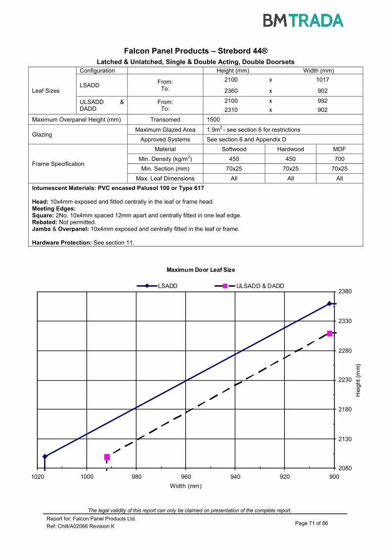
The legal validity of this report can only be claimed on presentation of the complete report.
Report for: Falcon Panel Products Ltd. Page 71 of 86
Ref: Chilt/A02066 Revision K
Maximum Door Leaf Size
2080
2130
2180
2230
2280
2330
2380
90092094096098010001020
Width (mm)
He
igh
t (m
m)
LSADD ULSADD & DADD
Falcon Panel Products – Strebord 44®
Latched & Unlatched, Single & Double Acting, Double Doorsets
Leaf Sizes
Configuration Height (mm) Width (mm)
LSADD From:
To:
2100 x 1017
2360 x 902
ULSADD & DADD
From: To:
2100 x 992
2310 x 902
Maximum Overpanel Height (mm) Transomed 1500
Glazing Maximum Glazed Area 1.9m
2 - see section 6 for restrictions
Approved Systems See section 6 and Appendix D
Frame Specification
Material Softwood Hardwood MDF
Min. Density (kg/m3) 450 450 700
Min. Section (mm) 70x25 70x25 70x25
Max. Leaf Dimensions All All All
Intumescent Materials: PVC encased Palusol 100 or Type 617
Head: 10x4mm exposed and fitted centrally in the leaf or frame head. Meeting Edges: Square: 2No. 10x4mm spaced 12mm apart and centrally fitted in one leaf edge. Rebated: Not permitted. Jambs & Overpanel: 10x4mm exposed and centrally fitted in the leaf or frame. Hardware Protection: See section 11.

The legal validity of this report can only be claimed on presentation of the complete report.
Report for: Falcon Panel Products Ltd. Page 72 of 86
Ref: Chilt/A02066 Revision K
Maximum Door Leaf Size
2100
2110
2120
2130
2140
900905910915920
W idth (mm)
He
igh
t (m
m)
LSADD & DADD & ULSADD
Falcon Panel Products – Strebord 44®
Latched & Unlatched, Single & Double Acting, Double Doorsets
Leaf Sizes
Configuration Height (mm) Width (mm)
LSADD & DADD & ULSADD
From: To:
2134 x 915
2134 x 915
Maximum Overpanel Height (mm) Transomed 1500
Glazing Maximum Glazed Area 1.9m
2 - see section 6 for restrictions
Approved Systems See section 6 and Appendix D
Frame Specification
Material Softwood Hardwood MDF
Min. Density (kg/m3) 450 450 700
Min. Section (mm) 70x25 70x25 70x25
Max. Leaf Dimensions All All All
Intumescent Materials: Therm-A-Seal or Pyroplex
Head: Square: 15x4mm exposed and centrally fitted in the leaf or frame head. Meeting Edges: Square: 2No. 10x4mm spaced 12mm apart and centrally fitted in one leaf edge. Rebated: 2No. 10x4mm one strip fitted centrally in each rebate. Jambs & Overpanel: 15x4mm exposed and centrally fitted in the leaf or frame. Hardware Protection: See section 11.

The legal validity of this report can only be claimed on presentation of the complete report.
Report for: Falcon Panel Products Ltd. Page 73 of 86
Ref: Chilt/A02066 Revision K
Maximum Door Leaf Size
2000
2100
2200
2300
2400
90092094096098010001020104010601080
Width (mm)
He
igh
t (m
m)
LSADD ULSADD & DADD
Falcon Panel Products – Strebord 44®
Latched & Unlatched, Single & Double Acting, Double Doorsets
Leaf Sizes
Configuration Height (mm) Width (mm)
LSADD From:
To:
2100 x 1065
2350 x 915
ULSADD & DADD
From: To:
2100 x 1040
2350 x 915
Maximum Overpanel Height (mm) Transomed 1500
Glazing Maximum Glazed Area 1.9m
2 - see section 6 for restrictions
Approved Systems See section 6 and Appendix D
Frame Specification
Material Softwood Hardwood MDF
Min. Density (kg/m3) 450 450 700
Min. Section (mm) 70x25 70x25 70x25
Max. Leaf Dimensions All All All
Intumescent Materials: PVC encased Palusol 100 or Type 617
Head: Square: 15x4mm exposed and fitted centrally in the leaf or frame head. Meeting Edges: Square: 2No. 10x4mm spaced 12mm apart and centrally fitted in one leaf edge. Rebated: 2No. 10x4mm one strip fitted centrally in each rebate. Jambs & Overpanel: 15x4mm exposed and centrally fitted in the leaf or frame. Hardware Protection: See section 11.

The legal validity of this report can only be claimed on presentation of the complete report.
Report for: Falcon Panel Products Ltd. Page 74 of 86
Ref: Chilt/A02066 Revision K
Maximum Door Leaf Size
2420
2520
2620
2720
2820
910930950970990101010301050107010901110Width (mm)
Heig
ht
(mm
)
LSADD ULSADD & DADD
Falcon Panel Products – Strebord 44®
Latched & Unlatched, Single & Double Acting, Double Doorsets
Leaf Sizes
Configuration Height (mm) Width (mm)
LSADD From:
To:
2440 x 1100
2800 x 915
ULSADD & DADD
From: To:
2440 x 1075
2750 x 915
Maximum Overpanel Height (mm) Transomed 1500
Glazing Maximum Glazed Area 1.9m
2 - see section 6 for restrictions
Approved Systems See section 6 and Appendix D
Frame Specification
Material Softwood Hardwood MDF
Min. Density (kg/m3) 450 450 700
Min. Section (mm) 70x25 70x25 70x25
Max. Leaf Dimensions All All All
Intumescent Materials: PVC encased Pyroplex
Head: Square: 15x4mm exposed and fitted centrally in the leaf or frame head. Meeting Edges: Square: 2No. 10x4mm spaced 10mm apart and centrally fitted in one leaf edge. Jambs & Overpanel: 15x4mm exposed and centrally fitted in the leaf or frame. Hardware Protection: See section 11.

The legal validity of this report can only be claimed on presentation of the complete report.
Report for: Falcon Panel Products Ltd. Page 75 of 86
Ref: Chilt/A02066 Revision K
Maximum Door Leaf Size
2720
2760
2800
2840
2880
2920
2960
3000
3040
3080
10901100111011201130114011501160
Width (mm)
He
igh
t (m
m)
LSADD ULSADD & DADD
Falcon Panel Products – Strebord 44®
Latched & Unlatched, Single & Double Acting, Double Doorsets
Leaf Sizes
Configuration Height (mm) Width (mm)
LSADD From:
To:
2800 x 1153
3059 x 1100
ULSADD & DADD
From: To:
2800 x 1128
3009 x 1100
Maximum Overpanel Height (mm) Transomed 1500
Glazing Maximum Glazed Area 1.9m
2 - see section 6 for restrictions
Approved Systems See section 6 and Appendix D
Frame Specification
Material Softwood Hardwood MDF
Min. Density (kg/m3) 450 450 700
Min. Section (mm) 70x25 70x25 70x25
Max. Leaf Dimensions All All All
Intumescent Materials: Pyroplex
Head: Square: 20x4mm exposed and fitted centrally in the leaf or frame head. Meeting Edges: Square: 2No. 10x4mm spaced 10mm apart and centrally fitted in one leaf edge. Jambs & Overpanel: 20x4mm exposed and centrally fitted in the leaf or frame. Hardware Protection: See section 11.
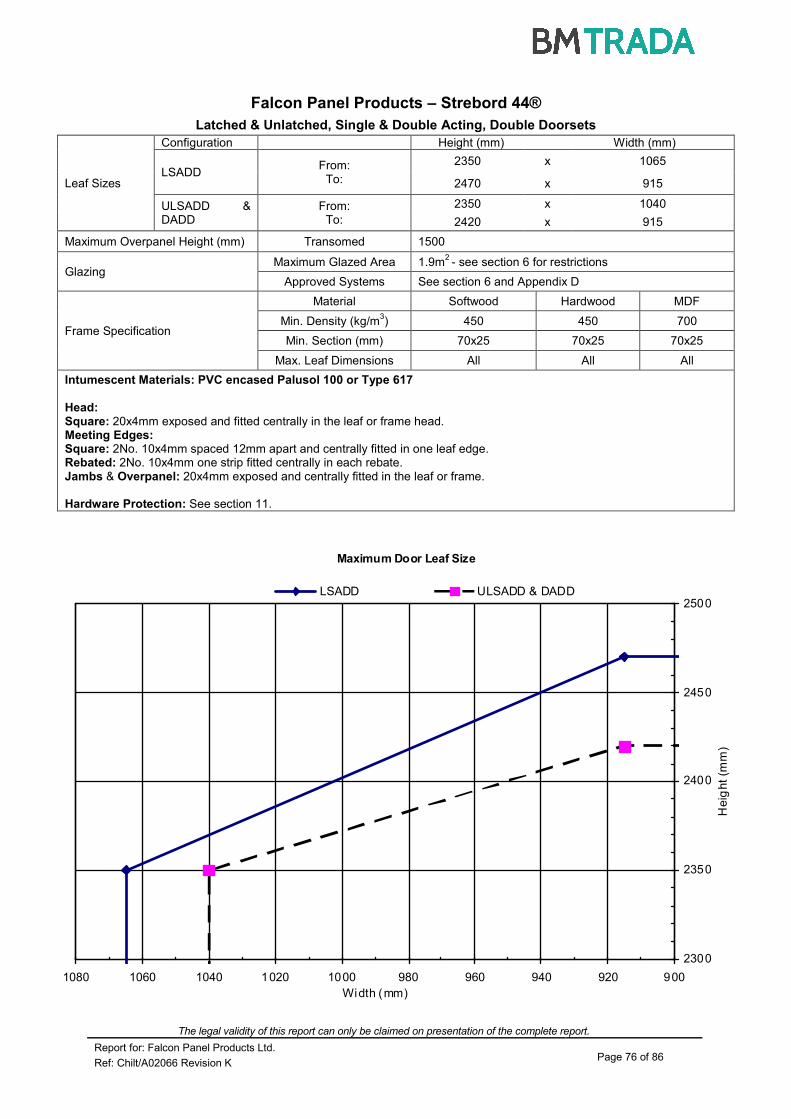
The legal validity of this report can only be claimed on presentation of the complete report.
Report for: Falcon Panel Products Ltd. Page 76 of 86
Ref: Chilt/A02066 Revision K
Maximum Door Leaf Size
2300
2350
2400
2450
2500
90092094096098010001020104010601080
Width (mm)
He
ight
(mm
)
LSADD ULSADD & DADD
Falcon Panel Products – Strebord 44®
Latched & Unlatched, Single & Double Acting, Double Doorsets
Leaf Sizes
Configuration Height (mm) Width (mm)
LSADD From:
To:
2350 x 1065
2470 x 915
ULSADD & DADD
From: To:
2350 x 1040
2420 x 915
Maximum Overpanel Height (mm) Transomed 1500
Glazing Maximum Glazed Area 1.9m
2 - see section 6 for restrictions
Approved Systems See section 6 and Appendix D
Frame Specification
Material Softwood Hardwood MDF
Min. Density (kg/m3) 450 450 700
Min. Section (mm) 70x25 70x25 70x25
Max. Leaf Dimensions All All All
Intumescent Materials: PVC encased Palusol 100 or Type 617
Head: Square: 20x4mm exposed and fitted centrally in the leaf or frame head. Meeting Edges: Square: 2No. 10x4mm spaced 12mm apart and centrally fitted in one leaf edge. Rebated: 2No. 10x4mm one strip fitted centrally in each rebate. Jambs & Overpanel: 20x4mm exposed and centrally fitted in the leaf or frame. Hardware Protection: See section 11.

The legal validity of this report can only be claimed on presentation of the complete report.
Report for: Falcon Panel Products Ltd. Page 77 of 86
Ref: Chilt/A02066 Revision K
Maximum Door Leaf Size
2300
2350
2400
2450
2500
90092094096098010001020104010601080
Width (mm)
He
igh
t (m
m)
LSADD ULSADD & DADD
Falcon Panel Products – Strebord 44®
Latched & Unlatched, Single & Double Acting, Double Doorsets
Leaf Sizes
Configuration Height (mm) Width (mm)
LSADD From:
To:
2350 x 1065
2470 x 915
ULSADD & DADD
From: To:
2350 x 1040
2420 x 915
Maximum Overpanel Height (mm) Transomed 1500
Glazing Maximum Glazed Area 1.9m
2 - see section 6 for restrictions
Approved Systems See section 6 and Appendix D
Frame Specification
Material Softwood Hardwood MDF
Min. Density (kg/m3) 450 450 700
Min. Section (mm) 70x25 70x25 70x25
Max. Leaf Dimensions All All All
Intumescent Materials: PVC encased Palusol 100 or Type 617
Head: Square: 25x4mm exposed and fitted centrally in the leaf or frame head. Meeting Edges: Square: 2No. 10x4mm spaced 12mm apart and centrally fitted in one leaf edge. Rebated: 2No. 10x4mm one strip fitted centrally in each rebate. Jambs & Overpanel: 25x4mm exposed and centrally fitted in the leaf or frame. Hardware Protection: See section 11.
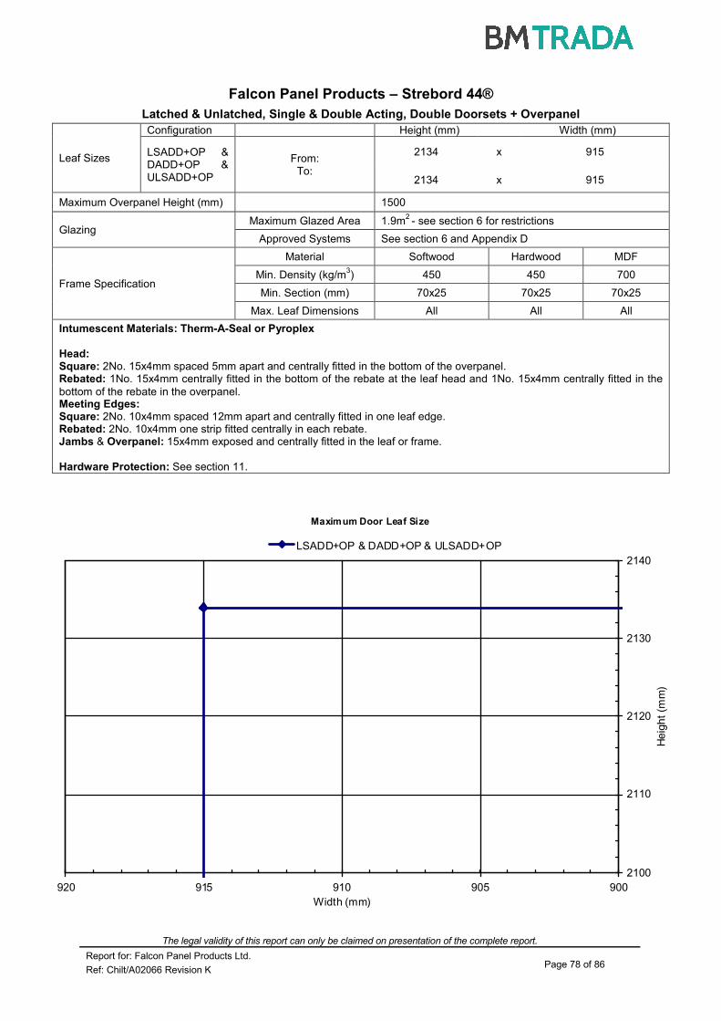
The legal validity of this report can only be claimed on presentation of the complete report.
Report for: Falcon Panel Products Ltd. Page 78 of 86
Ref: Chilt/A02066 Revision K
Maximum Door Leaf Size
2100
2110
2120
2130
2140
900905910915920
Width (mm)
He
igh
t (m
m)
LSADD+OP & DADD+OP & ULSADD+OP
Falcon Panel Products – Strebord 44®
Latched & Unlatched, Single & Double Acting, Double Doorsets + Overpanel
Leaf Sizes
Configuration Height (mm) Width (mm)
LSADD+OP & DADD+OP & ULSADD+OP
From: To:
2134 x 915
2134 x 915
Maximum Overpanel Height (mm) 1500
Glazing Maximum Glazed Area 1.9m
2 - see section 6 for restrictions
Approved Systems See section 6 and Appendix D
Frame Specification
Material Softwood Hardwood MDF
Min. Density (kg/m3) 450 450 700
Min. Section (mm) 70x25 70x25 70x25
Max. Leaf Dimensions All All All
Intumescent Materials: Therm-A-Seal or Pyroplex
Head: Square: 2No. 15x4mm spaced 5mm apart and centrally fitted in the bottom of the overpanel. Rebated: 1No. 15x4mm centrally fitted in the bottom of the rebate at the leaf head and 1No. 15x4mm centrally fitted in the
bottom of the rebate in the overpanel. Meeting Edges: Square: 2No. 10x4mm spaced 12mm apart and centrally fitted in one leaf edge. Rebated: 2No. 10x4mm one strip fitted centrally in each rebate. Jambs & Overpanel: 15x4mm exposed and centrally fitted in the leaf or frame. Hardware Protection: See section 11.
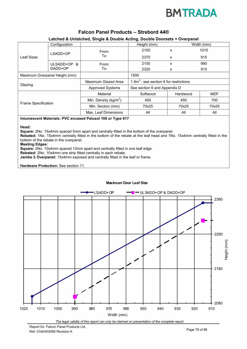
The legal validity of this report can only be claimed on presentation of the complete report.
Report for: Falcon Panel Products Ltd. Page 79 of 86
Ref: Chilt/A02066 Revision K
Maximum Door Leaf Size
2080
2180
2280
2380
910920930940950960970980990100010101020
Width (mm)
Heig
ht (m
m)
LSADD+OP ULSADD+OP & DADD+OP
Falcon Panel Products – Strebord 44®
Latched & Unlatched, Single & Double Acting, Double Doorsets + Overpanel
Leaf Sizes
Configuration Height (mm) Width (mm)
LSADD+OP From:
To:
2100 x 1015
2370 x 915
ULSADD+OP & DADD+OP
From: To:
2100 x 990
2320 x 915
Maximum Overpanel Height (mm) 1500
Glazing Maximum Glazed Area 1.9m
2 - see section 6 for restrictions
Approved Systems See section 6 and Appendix D
Frame Specification
Material Softwood Hardwood MDF
Min. Density (kg/m3) 450 450 700
Min. Section (mm) 70x25 70x25 70x25
Max. Leaf Dimensions All All All
Intumescent Materials: PVC encased Palusol 100 or Type 617
Head: Square: 2No. 15x4mm spaced 5mm apart and centrally fitted in the bottom of the overpanel. Rebated: 1No. 15x4mm centrally fitted in the bottom of the rebate at the leaf head and 1No. 15x4mm centrally fitted in the
bottom of the rebate in the overpanel. Meeting Edges: Square: 2No. 10x4mm spaced 12mm apart and centrally fitted in one leaf edge. Rebated: 2No. 10x4mm one strip fitted centrally in each rebate. Jambs & Overpanel: 15x4mm exposed and centrally fitted in the leaf or frame. Hardware Protection: See section 11.

The legal validity of this report can only be claimed on presentation of the complete report.
Report for: Falcon Panel Products Ltd. Page 80 of 86
Ref: Chilt/A02066 Revision K
Maximum Door Leaf Size
2100
2200
2300
2400
2500
2600
92094096098010001020104010601080110011201140
Width (mm)
He
igh
t (m
m)
LSASD ULSASD
Falcon Panel Products – Strebord 44® - Nordform Steel Door Frames
Latched & Unlatched, Single Acting, Single Doorsets
Leaf Sizes
Configuration Height (mm) Width (mm)
LSASD From:
To:
2150 x 1145
2622 x 931
ULSASD From:
To:
2150 x 1120
2572 x 931
Maximum Overpanel Height (mm) Not permitted
Glazing Maximum Glazed Area 1.9m
2 - see section 6 for restrictions
Approved Systems See section 6 and Appendix D
Frame Specification Material Mild steel
Specification See Appendix A1
Intumescent Materials: Pyroplex Rigid Box FO8600 Graphite Seal
Head: 20x4mm fitted centrally in the leaf head.
Jambs: 20x4mm exposed and centrally fitted in the leaf edges. Hardware Protection: See section 11.
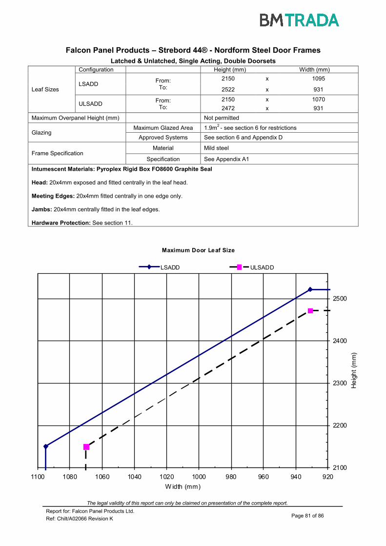
The legal validity of this report can only be claimed on presentation of the complete report.
Report for: Falcon Panel Products Ltd. Page 81 of 86
Ref: Chilt/A02066 Revision K
Maximum Door Leaf Size
2100
2200
2300
2400
2500
920940960980100010201040106010801100
W idth (mm)
He
igh
t (m
m)
LSADD ULSADD
Falcon Panel Products – Strebord 44® - Nordform Steel Door Frames
Latched & Unlatched, Single Acting, Double Doorsets
Leaf Sizes
Configuration Height (mm) Width (mm)
LSADD From:
To:
2150 x 1095
2522 x 931
ULSADD From:
To:
2150 x 1070
2472 x 931
Maximum Overpanel Height (mm) Not permitted
Glazing Maximum Glazed Area 1.9m
2 - see section 6 for restrictions
Approved Systems See section 6 and Appendix D
Frame Specification Material Mild steel
Specification See Appendix A1
Intumescent Materials: Pyroplex Rigid Box FO8600 Graphite Seal
Head: 20x4mm exposed and fitted centrally in the leaf head.
Meeting Edges: 20x4mm fitted centrally in one edge only.
Jambs: 20x4mm centrally fitted in the leaf edges. Hardware Protection: See section 11.

The legal validity of this report can only be claimed on presentation of the complete report.
Report for: Falcon Panel Products Ltd. Page 82 of 86
Ref: Chilt/A02066 Revision K
Maximum Door Leaf Size
2180
2230
2280
2330
2380
2430
2480
89091093095097099010101030
Width (mm)
Heig
ht
(mm
)
LSASD ULSASD
Falcon Panel Products – Strebord 54® - FD30 Steel Door Frames
Latched & Unlatched, Single Acting, Single Doorsets
Leaf Sizes
Configuration Height (mm) Width (mm)
LSASD From:
To:
2200 x 1038
2515 x 896
ULSASD From:
To:
2200 x 1013
2465 x 896
Maximum Overpanel Height (mm) Not permitted
Glazing Maximum Glazed Area 1.9m
2 - see section 6 for restrictions
Approved Systems See section 6 and Appendix D
Frame Specification
Min. Section 171 x 38 (excl. stop)
Material Mild steel
Specification See Appendix A2
Intumescent Materials: PVC encased Therm-A-Seal and Therm-A-Flex
Head: 25x4mm Therm-A-Seal exposed and fitted centrally in the leaf head.
2No. 10x2mm Therm-A-Flex centrally fitted spaced 15mm apart and concealed behind the lipping. Jambs: 25x4mm Therm-A-Seal exposed and centrally fitted in the leaf.
2No. 10x2mm Therm-A-Flex centrally fitted spaced 15mm apart and concealed behind the lipping. Threshold: 20x2mm Therm-A-Flex centrally fitted in the bottom of the leaf.
Hardware Protection: See section 11.

The legal validity of this report can only be claimed on presentation of the complete report.
Report for: Falcon Panel Products Ltd. Page 83 of 86
Ref: Chilt/A02066 Revision K
Maximum Door Leaf Size
2180
2230
2280
2330
2380
2430
2480
1050107010901110113011501170119012101230
W idth (mm)
He
igh
t (m
m)
LSASD ULSASD
Falcon Panel Products – Strebord 54® - FD30 Steel Door Frames
Latched & Unlatched, Single Acting, Single Doorsets
Leaf Sizes
Configuration Height (mm) Width (mm)
LSASD From:
To:
2218 x 1219
2507 x 1078
ULSASD From:
To:
2218 x 1194
2457 x 1078
Maximum Overpanel Height (mm) Not permitted
Glazing Maximum Glazed Area 1.9m
2 - see section 6 for restrictions
Approved Systems See section 6 and Appendix D
Frame Specification
Min. Section 171 x 38 (excl. stop)
Material Mild steel
Specification See Appendix A2
Intumescent Materials: PVC encased Therm-A-Seal and Therm-A-Flex
Head: 25x4mm Therm-A-Seal exposed and fitted centrally in the leaf head.
25x2mm Therm-A-Flex centrally fitted underneath the Therm-A-Seal. Jambs: 25x4mm Therm-A-Seal exposed and centrally fitted in the head of the leaf.
25x2mm Therm-A-Flex centrally underneath the Therm-A-Seal. Threshold: 20x2mm Therm-A-Flex centrally fitted in the bottom of the leaf.
Hardware Protection: See section 11.
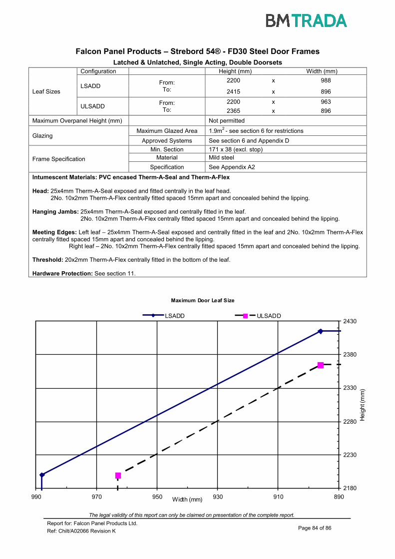
The legal validity of this report can only be claimed on presentation of the complete report.
Report for: Falcon Panel Products Ltd. Page 84 of 86
Ref: Chilt/A02066 Revision K
Maximum Door Leaf Size
2180
2230
2280
2330
2380
2430
890910930950970990 Width (mm)
He
igh
t (m
m)
LSADD ULSADD
Falcon Panel Products – Strebord 54® - FD30 Steel Door Frames
Latched & Unlatched, Single Acting, Double Doorsets
Leaf Sizes
Configuration Height (mm) Width (mm)
LSADD From:
To:
2200 x 988
2415 x 896
ULSADD From:
To:
2200 x 963
2365 x 896
Maximum Overpanel Height (mm) Not permitted
Glazing Maximum Glazed Area 1.9m
2 - see section 6 for restrictions
Approved Systems See section 6 and Appendix D
Frame Specification
Min. Section 171 x 38 (excl. stop)
Material Mild steel
Specification See Appendix A2
Intumescent Materials: PVC encased Therm-A-Seal and Therm-A-Flex
Head: 25x4mm Therm-A-Seal exposed and fitted centrally in the leaf head.
2No. 10x2mm Therm-A-Flex centrally fitted spaced 15mm apart and concealed behind the lipping. Hanging Jambs: 25x4mm Therm-A-Seal exposed and centrally fitted in the leaf.
2No. 10x2mm Therm-A-Flex centrally fitted spaced 15mm apart and concealed behind the lipping. Meeting Edges: Left leaf – 25x4mm Therm-A-Seal exposed and centrally fitted in the leaf and 2No. 10x2mm Therm-A-Flex
centrally fitted spaced 15mm apart and concealed behind the lipping. Right leaf – 2No. 10x2mm Therm-A-Flex centrally fitted spaced 15mm apart and concealed behind the lipping. Threshold: 20x2mm Therm-A-Flex centrally fitted in the bottom of the leaf.
Hardware Protection: See section 11.

The legal validity of this report can only be claimed on presentation of the complete report.
Report for: Falcon Panel Products Ltd. Page 85 of 86
Ref: Chilt/A02066 Revision K
Maximum Door Leaf Size
2050
2150
2250
2350
2450
2550
2650
2750
2850
2950
85090095010001050110011501200
Width (mm)
He
igh
t (m
m)
LSASD ULSASD & DASD
Falcon Panel Products – CS Edge Protectors/Acrovyn Wrap
Latched & Unlatched, Single & Double Acting, Single Doorsets
Leaf Sizes
Configuration Height (mm) Width (mm)
LSASD From:
To:
2100 x 1161
2900 x 900
ULSASD & DASD
From: To:
2100 x 1140
2620 x 900
Maximum Overpanel Height (mm) Transomed 2000
Glazing Maximum Glazed Area 1.9m
2 - see section 6 for restrictions
Approved Systems See section 6 and appendix D
Frame Specification
Min. Section (mm) 70 x 25 70 x 25 70 x 25
Material Hardwood Softwood MDF
Min. Density (kg/m3) 450 450 700
Intumescent Materials: Type 617 – Lorient Polyproducts Ltd.
Head: Square: 1No. 15x4mm fitted centrally in the leaf head or frame reveal. Jambs & Overpanels: 1No. 15x4mm fitted centrally in the leaf edge. Hardware Protection: See section 11.

The legal validity of this report can only be claimed on presentation of the complete report.
Report for: Falcon Panel Products Ltd. Page 86 of 86
Ref: Chilt/A02066 Revision K
Maximum Door Leaf Size
2050
2100
2150
2200
2250
2300
2350
2400
850900950100010501100Width (mm)
He
ight
(mm
)
LSADD ULSADD & DADD
Falcon Panel Products – CS Edge Protectors/Acrovyn Wrap
Latched & Unlatched, Single & Double Acting, Double Doorsets
Leaf Sizes
Configuration Height (mm) Width (mm)
LSADD From:
To:
2100 x 1065
2350 x 900
ULSADD & DADD
From: To:
2100 x 1040
2350 x 900
Maximum Overpanel Height (mm) Transomed 1500
Glazing Maximum Glazed Area 1.9m
2 see section 6 for restrictions
Approved Systems See section 6 and appendix D
Frame Specification
Min. Section (mm) 70 x 25 70 x 25 70 x 25
Material Hardwood Softwood MDF
Min. Density (kg/m3) 450 450 700
Intumescent Materials: Type 617 – Lorient Polyproducts Ltd.
Head: Square: 1No. 15x4mm fitted centrally in the leaf head or frame reveal. Meeting Edges: Square: 1No. 15x4mm fitted centrally in the meeting edges of both leaves.
Jambs & Overpanels: 1No. 15x4mm fitted centrally in the leaf edge. Hardware Protection: See section 11.

BM TRADA provides independent certification, testing, inspection, training and technical services around the world. We help customers large and small to prove their business and product credentials and to improve performance and compliance. With an international presence across many industry sectors, we offer a special focus and long history of technical excellence in supply chain certification, product certification and testing, and technical services to the timber, building, fire and furniture industries.
bmtradagroup.com +44 (0) 1494 [email protected]
CHILTERN INTERNATIONAL FIRE LTD CHILTERN HOUSE, STOCKING LANE, HUGHENDEN VALLEY, HIGH WYCOMBE, BUCKS, HP14 4ND, UK
REGISTERED IN ENGLAND NO. 3125010