Embed Size (px)
Citation preview
JONESBORO HIGH SCHOOL ENGINEERNG AND TECHNOLOGY
CAD Mechanical Part 1 Assignment 7 Page 1
In this assignment you will apply the trim, real time zoom, pan commands, as well as skills
learned in earlier assignments.
1. When AutoCAD's menu appears, scroll down and select the Otto 2016.dwt template file
as you have on the previous assignments.
2. Complete the title block and by typing the information into the block. The drawing will
be drawn full scale.
3. Insert the drawing title and drawing number illustrated below:
Tic Tac Toe Board C12
4. Remember to turn the snap back on while drawing lines and dimensioning the drawing.
Note: If a pop ask for you to make a selection, choose the one that is recommended.
1. After the border appears and you have changed to the object layer, begin drawing the
drawing by constructing a 6” square using Polyline command.
Use the Offset command to produce another polyline 1/4” inside the first one.
Use the Explode command to explode the inner polyline into four separate lines.
CAD Mechanical – Part 1 Assignment 7
Trim & Zoom Functions Objectives
Getting Started
Offset Command
JONESBORO HIGH SCHOOL ENGINEERNG AND TECHNOLOGY
CAD Mechanical Part 1 Assignment 7 Page 2
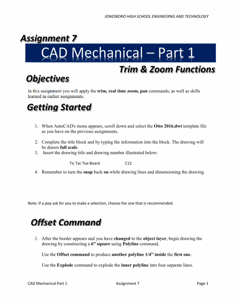
The drawing should now appear as below:
2. Again use the Offset command, and offset the four inside lines 3/8”.
JONESBORO HIGH SCHOOL ENGINEERNG AND TECHNOLOGY
CAD Mechanical Part 1 Assignment 7 Page 3
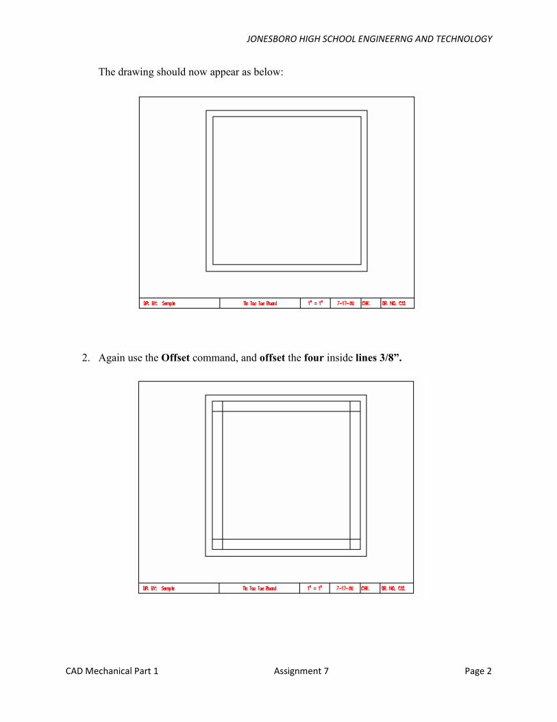
3. Continue the Offset command and offset the four inside lines a distance of 1-1/2”.
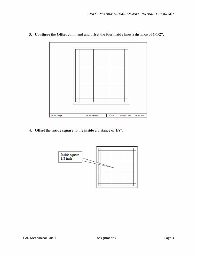
4. Offset the inside square to the inside a distance of 1/8”.
JONESBORO HIGH SCHOOL ENGINEERNG AND TECHNOLOGY
CAD Mechanical Part 1 Assignment 7 Page 4
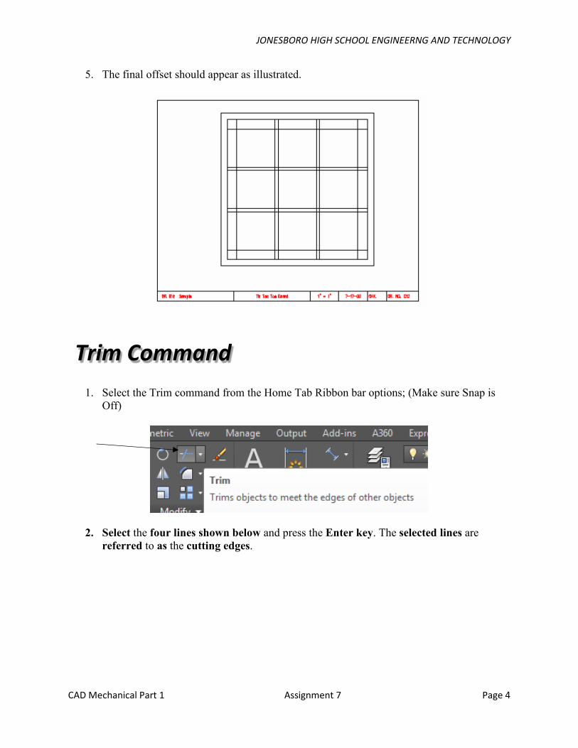
5. The final offset should appear as illustrated.
1. Select the Trim command from the Home Tab Ribbon bar options; (Make sure Snap is
Off)
2. Select the four lines shown below and press the Enter key. The selected lines are
referred to as the cutting edges.
Trim Command
JONESBORO HIGH SCHOOL ENGINEERNG AND TECHNOLOGY
CAD Mechanical Part 1 Assignment 7 Page 5
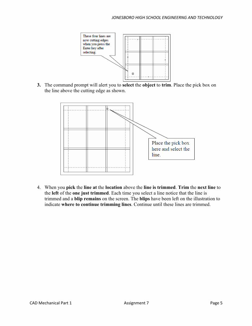
3. The command prompt will alert you to select the object to trim. Place the pick box on
the line above the cutting edge as shown.
4. When you pick the line at the location above the line is trimmed. Trim the next line to
the left of the one just trimmed. Each time you select a line notice that the line is
trimmed and a blip remains on the screen. The blips have been left on the illustration to
indicate where to continue trimming lines. Continue until these lines are trimmed.
JONESBORO HIGH SCHOOL ENGINEERNG AND TECHNOLOGY
CAD Mechanical Part 1 Assignment 7 Page 6
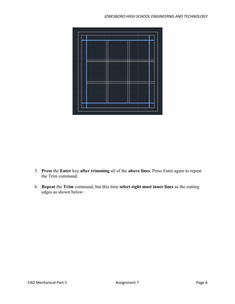
5. Press the Enter key after trimming all of the above lines. Press Enter again to repeat
the Trim command.
6. Repeat the Trim command, but this time select eight most inner lines as the cutting
edges as shown below:
JONESBORO HIGH SCHOOL ENGINEERNG AND TECHNOLOGY
CAD Mechanical Part 1 Assignment 7 Page 7
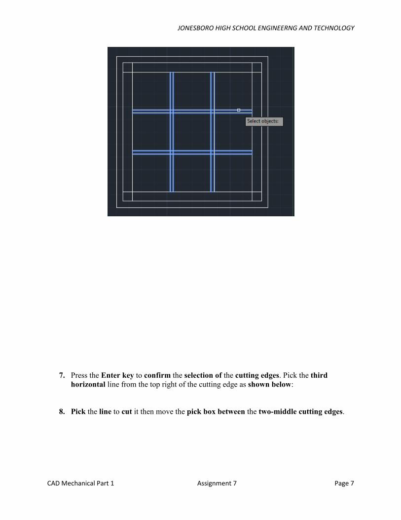
7. Press the Enter key to confirm the selection of the cutting edges. Pick the third
horizontal line from the top right of the cutting edge as shown below:
8. Pick the line to cut it then move the pick box between the two-middle cutting edges.
JONESBORO HIGH SCHOOL ENGINEERNG AND TECHNOLOGY
CAD Mechanical Part 1 Assignment 7 Page 8
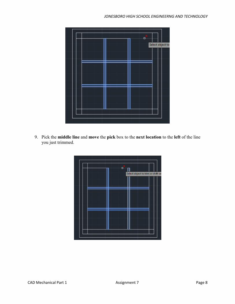
9. Pick the middle line and move the pick box to the next location to the left of the line
you just trimmed.
JONESBORO HIGH SCHOOL ENGINEERNG AND TECHNOLOGY
CAD Mechanical Part 1 Assignment 7 Page 9
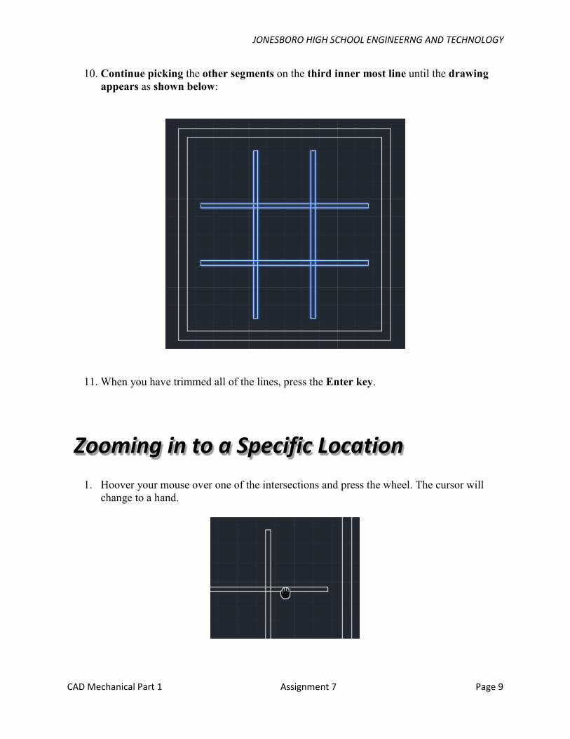
10. Continue picking the other segments on the third inner most line until the drawing
appears as shown below:
11. When you have trimmed all of the lines, press the Enter key.
1. Hoover your mouse over one of the intersections and press the wheel. The cursor will
change to a hand.
Zooming in to a Specific Location
JONESBORO HIGH SCHOOL ENGINEERNG AND TECHNOLOGY
CAD Mechanical Part 1 Assignment 7 Page
10
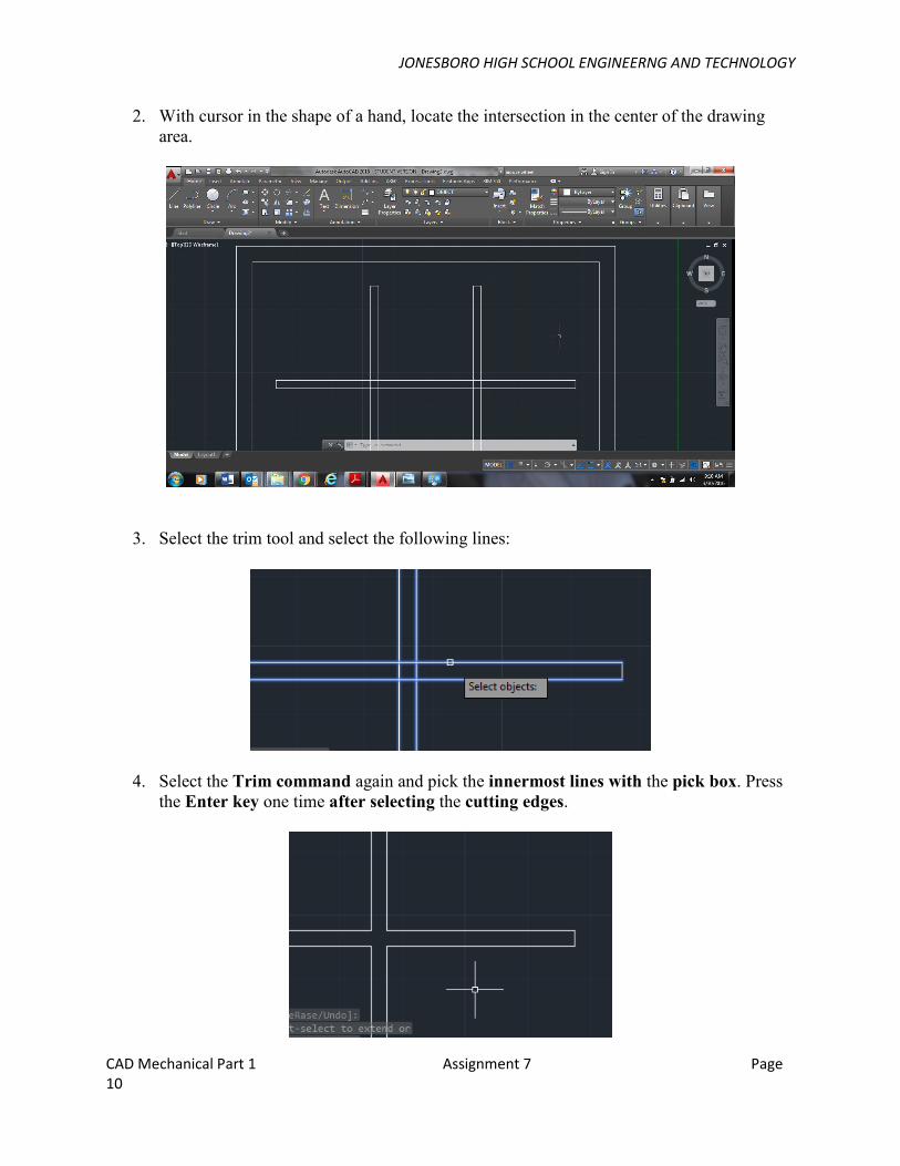
2. With cursor in the shape of a hand, locate the intersection in the center of the drawing
area.
3. Select the trim tool and select the following lines:
4. Select the Trim command again and pick the innermost lines with the pick box. Press
the Enter key one time after selecting the cutting edges.
JONESBORO HIGH SCHOOL ENGINEERNG AND TECHNOLOGY
CAD Mechanical Part 1 Assignment 7 Page
11
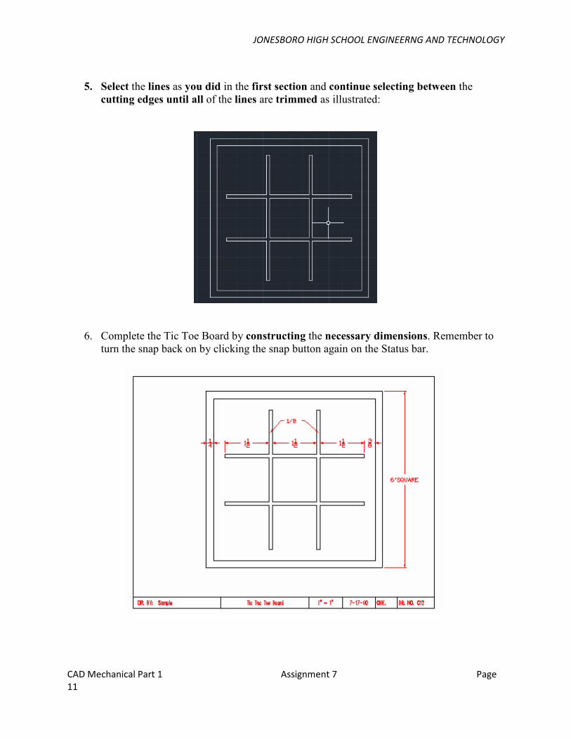
5. Select the lines as you did in the first section and continue selecting between the
cutting edges until all of the lines are trimmed as illustrated:
6. Complete the Tic Toe Board by constructing the necessary dimensions. Remember to
turn the snap back on by clicking the snap button again on the Status bar.

JONESBORO HIGH SCHOOL ENGINEERNG AND TECHNOLOGY
CAD Mechanical Part 1 Assignment 7 Page
12
Trim Zoom Snap
Terms to Know