Embed Size (px)
Citation preview
)I\ATARr Documentation Series
Owner's Manual
Every effort has been made to ensure the accuracy of the product documentation in this manual. However, because Atari Corporation is constantly improving and updating its computer hardware and software, it is unable to guarantee the accuracy of printed material after the date of publication and disclaims liability for changes, errors, or omissions.
Atari®, the Atari logo, Atari PC3™, PCF554™, PCM124™, and SF314™ are trademarks or registered trademarks of Atari Corporation. Adaptec™ is a trademark of Adaptec Inc. GEM®, GEM® Desktop™, GEM® Paint™ . and GEM® Write™ are trademarks or registered trademarks of Digital Research Inc. Epson® is a registered trademark of SeikoEpson Corporation, Japan. Hercules® is a registered trademark of Hercules Computer Technology, Inc. Intel® is a registered trademark of Intel Corporation. AT®, IBM®, and XT™ are trademarks or registered trademarks of International Business Machines Corporation. Microsoft® and MS-DOS® are registered trademarks of Microsoft Corporation. OMTI® is a registered trademark of Scientific Microsystems Inc. Velcro® is a registered trademark of Velcro USA Inc.
Reproduction of all or any portions of this manual is not allowed without the specific written consent of Atari Corporation.
)I\_ATARr Copyright© 1988, Atari Corporation Sunnyvale, CA 94086 All rights reserved.
Jl�ATARr Documentation. Series
Owner's Manual
TABLE OF CONTENTS
INTRODUCTION ... ... ........... ... ........ .... . .. . ..... ..... ........ ... ... .. ... . .. . ... ...... 1 Welcome to the Atari PC3 ........................................................... 1 Using This Manual ............................................................. -�.. .. .. .. . 2
CHAPTER 1: GETTING STARTED .. . .. ... .... .. . .. . .. ...... ... ... .... ... ... ... .. 5 Atari PC3 System Components .. .. . .. .. .. .. .. .. .. . ......... ..... ...... . . . ... .... 5
Computer and Disk Drives .. . .. . .. . . .. . .. .. . . .. .. .. . .. .. . .. . . . . .. . . . . .. . .. . . . . .. . . . . . .. 5 Keyboard. Monitor. and Mouse .. .. . .. .. .. . . .. .. . .... .. .... . .. .. .. .. .. . .. .. .. . . . . .. . 6 Numeric Data Processor and RAM Chips . . .. . . . . . . .. . . .. . . . .. . .. . . . .. . .. .. . .. 6 Optional Devices . . . . . . . . . . . . . . . . . . . . . . . . . . . . . . . . . . . . . . . . . . . . . . . . . . . . . . . . . . . . . . . . . . . . . . . . . . . 6
. Connecting the Atari PC3 System .. . .. .. . . . .. . .. .. . . .. . .. . .. . . . . . . . .. . .. . . .. .. 7 Switching the Atari PC3 System On and Off . ... .......... .... ..... .... 10
Switchi�g On the System .. .. .. . .. .. .. .. .. .. . .. .. . .. .. .. .. .. .. .. .. .. . .. . . . . . .. . ... . . . . . 10 Switching Off the System .. .. . . . . . .. . .. . . .. .. .. . .. . . .. . . . .. . . .. . .. .. . .. . .. .. .. . . .. .. .. . 13
Ports and Features .. ... .................................. ............ ... .. ... .... ........ 13 Keyboard . . .. . . .. . .. . . .. .. . .. .. . .. . .. . . . . .. .. . . . . ... . .. . .. . . . .. .. . .. .. .. . .. .. . .. . .. . . . . .. . . . .. . . 13 The Computer's Back Panel ................................................... .'...... 15 The Computer's Right Side Panel . .. ............. ... ... .. .. .. ... . .. . . .. .. . .. .... .. 17
CHAPTER 2: ATARI PC3 SYSTEM OVERVIEW ........................ 19 MS-DOS.......................................................................................... 19 One-Drive and Multi-Drive Systems . . . . .. .. ... .. . . . .. . . . . .. . .. . . . . . . . .. . . .. .. 19 Floppy Disks ...................................................... .'............................ 20
Write-Protecting Disks . . . . . . . . . . . . . . . . . . . . . . . . . . . . . . . . . . . . . . . . . . . . . . . . . . . ... . . . . . . . . . . . . . . 21 Copying the Program Disks .. . . . . .. . . . .. . . . . .. . . .. . .. . .. . . .. .. . . . ... .. . .. . . .... . .. .. 22 The CONFIG.SYS and AUTOEXEC.BAT Files........................ 23
The CONFIG.SYS File . ........... .. ... .. ... ... ... ....... ........... ... ... ........ ... .. . 23 The AUTOEXEC.BAT File............................................................. 24
The Tree Structure of Directories and Files .. .. . . .. .. . .. . . .. . .. .... . . . . 25 Filenames . .. . . . . . . . . . .. . .. . . . .. . .. . .. . .. . . .. . . . . . . . .. .. . .. .. .. . . . . .. . . . . . . .. . .. . .. . .. . . . . . . . . . . . 26 Changing the Drive Designation .. .. .. . .. . .... . . . . . . . . . .. . .. .. . . . . . .. . . . . . .. .. . . 28
Atari PC3 Special Features . .. . ... .. . ..... .... ... ...... ........ ... ... . ... .. .. . . .. .. . 29 Setting the Real-Time Clock . . . . . . . . . . . . .. . . . . . . . . . . . . . . . . . . . . . . .. . . . . . . . . . . . . . . . . . . . . 29 Changing System Speed . . . . . . . . . . . . . . . . . . . . . . . . .. . . . . . . . . . . . .. . . . . . . . . . . . . . . . . . . . . . . . . 30 Selecting Monitor Display Modes . . . . . . . . . . . . . . . . . . . . . . . . . . . .. . . . . . . . . . . . . . . . .. . . . . 32 Setting the Key Click Feature . . .. . .. . .. ... .. ....... .. . . .. ... . ..... ... . ... .. . . .. ...... 32 Installing the Mouse for Use with Non-GEM Programs . . . . . . . . . . . . . . . . . . 33
CHAPTER 3: INTRODUCTION TO MS-DOS COMMANDS . . ... . 35 Commands . . . . . . . . . . . . . . . . . . . . . . . . . . . . . . . . . . . . . . . . . . . . . . . . . . . . . . . . . . . . . . . . . . . . . . . . . . . . . . . . . . . . . . 35
Parameters . . . . . . . . . . . . . . . . . . . . . . . . . . . . . . . . . . . . . . . . . . . . . . . . . . . . . . . . . . . . . . . . . . . . . . . . . . . . . . . . . . . . 35 Command Syntax . . . . . . . . . . . . . . . . . . . . . . . . . . . . . . . . . . . . . . . . . . . . . . . . . . . . . . . . . . . . . . . . . . . . . . . . . . 37 Editing Commands . . . . . . . . . . . . . . . . . . . . . . . . . . . . . . . . . . . . . . . . . . . . . . . . . . . . . . . . . . . . . . . . . . . . . . . . 39
Preparing Floppy Disks . . . . . . . . . . . . . .. . . . . . . . . . . . . . . . . . . . . . . . . . . . . . . . . . . . . . . . . . . . . . . . . . 39 FORMAT ....................................................................................... 39
Copying Disks . . . . . . . . . . . . . . . . . . . . . . . . . . . . . . . . .. . . ... . . . . . . . . . . . . . . . . . . . . . . . .. . . . . . . . . . . .. . . . . 40 DISK COPY .. . ... . ..... ...... .. ... . . . . . ... .. . .. .. . . .... .. ..... ...... .. . . . . .. .. . . .. . ... .. ... . .. . 40
Copying Files . . . . . . . . . . . . . . . . . . . . . . .. . . . . . . . . . . . . . . . . . . . . . . . . . . . . . . . . . . . . . . . . . . . . . . . . . . . . . . . . . 42 COPY ............................................................................................ 42
Viewing, Renaming, and Erasing Files . .. . . . ......... ............. .. . .. . .. . 44
TYPE ............................................................................................. 44 REN (REName) . . . . . . . . . . . . . . . . . . . .. . . . . . . . . . . . .. . . . . . . . . . . . . . . . . . . . . . . . . . . . . . . . . . . . . . . .. . . . 44 DEL (DELete) and ERASE . . . . . . . . . . . . . . . . . . . . . . . . . . . . . .. . . . . . . . . . . . . . . . . . . . . . . .. . . . . . 45
Working with Directories .. . .. ..... .. ... .. . .. . ... . ..... ......... .. .. . .. . ............ ... 46 DIR (DIRectory) ............................................................................. 46 MKDIR (MaKe DIRectory) .......... :.................................................. 47 CHOIR (CHange DIRectory) ......................................................... 47 RMDIR (ReMove DIRectory) ......................................................... 48 TREE ............................................................................................. 48 PATH ............................................................................................. 49
Checking Disks. Directories. and Files .. . .. .......... ..... ... .. . . .. . . .. .. . . 50 CHKDSK (CHecK DiSK) ............................................................... 50
Printing Files . . . . . . . . . . . . . . . . . . . . . . . . . . . . . . . . . . .. . . . . . . . . . . . . . . . . . . ... . . . . . . . . . . . . . . . . . . . . . . . . . 51PRINT ............................................................................................ 51 MODE ............................................................................................ 52
Monitor Display Mode Commands . . . . . . . . . .. . . . . . . . . . . . . . . . . . . . . . . . . . . .. . . .. . . 52 A Few Other Useful Commands................................................. 55
CURSOR ....................................................................................... 55 PROMPT ....................................................................................... 56 CLS ( Clear Screen) . . . . . . . . . . . . . . . . . . . . . . . . . . . . . . . . . . . . . . . . . . . . . . . . . . . . . . . . . . . . . . . . . . . . . . 56
Common MS-DOS Error Messages . . . . . . . . . . . . . . . . . . . . . . . . . . . . . . . . . . . . . . . . . . . 57
APPENDIX A: SYSTEM MAINTENANCE ...................................... 61
APPENDIX B: INSTALLING EXTRA RAM AND THE NUMERIC DAT A PROCESSOR . . .. . ... . . ... ... . ... . ....... .. . . . . 65
APPENDIX C: INST ALLING EXPANSION BOARDS AND INTERNAL DRIVES ................................................................ 69
APPENDIX D: CONNECTING EXTERNAL FLOPPY 6>RIVES.............................................................................. 77
APPENDIX E: PREPARING AND WORKING WITH A HARD DISK.................................................................................... 79
APPENDIX F: AT ARI PC3 SPECIFICATIONS .. ........ .. ... ... . . . . . . .. . . 93
APPENDIX G: AT ARI PC3 CONNECTOR PINOUTS . . . . . . . . . .. . .. . . . 97
APPENDIX H: POWER CONNECTION IN THE UNITED KINGDOM ............................................................ 101
GLOSSARY ....................................................................................... 103
CUSTOMER SUPPORT .................................................................. 113
INDEX ................................................................................................ 115
INTRODUCTION
Welcome to the Atari PC3
If you are new to the world of personal computers, you'll find the Atari PC3 to be a powerful, reliable system that's easy to set up and operate. And if you're a seasoned PC user, you'll appreciate the many features built into the Atari PC3--features you'd have to add on to other systems-including:
• A high-speed 8088 processor so you can choose between standard PCand turbo operating speeds.
• 512 kilobytes of RAM with expansion capability to 640 kilobytes on themotherboard.
• An Enhanced Graphics Adapter (EGA) compatible video subsystem forsuperior screen resolution and color selection.
• Support for an optional numeric data processor to speed calculations.
• Drive bays that accommodate two internal drives.
• A port for up to two Atari external floppy disk drives, the Atari PCF554(5V4-inch) drive and/or the Atari SF314 (3V2-inch) drive.
• Interfaces for both serial and parallel peripherals .
. • A monitor port that supports EGA. color. and monochrome monitors.
• A battery backed-up real-time clock.
• An IBM PC AT-layout keyboard.
•·Five slots for XT-style expansion boards.
• A mouse for controlling GEM Desktop and other utilities andapplications.
Note: Standard options on the Atari PC3 vary. Your version may have either one internal floppy drive. two internal floppy drives. or one internal floppy and one internal hard drive.
Using This Manual
To get top performance from your Atari PC3. you'll want to set up and operate it correctly from the start. This manual explains how to do that in clear, nontechnical language that's easy to understand. Once you're familiar with using your Atari PC3, this manual can serve as a reference guide to individual procedures and specific information.
You must make backup copies of the disks supplied with your Atari PC3. Backup copies protect you from accidentally losing or damaging the data on the original disks. Use the backup copies as your working disks and safely store the originals. For instructions, see Copying the Program Disks
in Chapter 2 of this manual.
Read the manual chapters in sequence the first time through, letting them guide you through setting up your system to a thorough explanation of system operation. Atari PC3 owners in the United Kingdom should see Appendix 1-f'for additional instructions when connecting their systems. A summary of each manual section follows:
Chapter 1: Getting Started describes the Atari PC3 components and explains how to connect and switch on the system.
Chapter 2: Atari PC3 System Overview looks at how your Atari PC3 works and explains how to use MS-DOS, the Atari PC3's operating system. You'll also find helpful information on using system features, working with floppy disks. and making backup copies of the program disks.
Chapter 3: Introduction to MS-DOS Commands explains how to use MS-DOS commands and provides a reference for often-used commands. The last section of the chapter explains common error messages you may see while working with your system.
Appendix A: System Maintenance explains how to identify and correct common operating problems and take care of your system.
Appendix B: Installing Extra RAM and the Numeric Data Processor explains how to install those optional features.
2
Appendix C: Installing Expansion Boards and Internal Drives explains how to install optional functional boards and internal drives (including a hard disk drive) on the Atari PC3.
Appendix D: Connecting External Floppy Drives explains how to connect up to two external floppy drives to your Atari PC3 system.
Appendix E: Preparing and Working with a Hard Disk explains how to prepare and operate an optional hard disk once it's connected to your Atari PC3.
Appendix F: Atari PC3 Specifications summarizes the major features and requirements of the system.
Appendix G: Atari PC3 Connector Pinouts shows the pin assignments of the Atari PC3's peripheral ports.
Appendix H: Power Connection in the United Kingdom includes additional set-up instructions for Atari PC3 owners in the United Kingdom.
The Glossary defines common technical terms used in this manual.
Customer Support tells you where to find more information about the Atari PC3 and all Atari computer products.
The Index helps you locate terms and procedures used or explained in the manual.
Paragraphs marked Note or Warning appear throughout the manual. Notes contain useful hints and other information relevant to the topic being discussed. Warnings alert you to potential problems and suggest ways to avoid them.
In this manual. characters in dark type enclosed by square brackets ([ J) represent keys on your Atari PC3 keyboard. In cases where a process or function requires using two or three keys, the keys are listed together in order. For example. [Ctrl] [$) means to hold down the [Ctrl] key while pressing the [SJ key: [Ctrl] [Alt] [Del] means to hold down the [Ctrl] and [Alt] keys while pressing the [Del] key.
3
CHAPTER 1
GETTING STARTED
Set up your Atari PC3 in a roomy workspace that's both healthy for the c;omputer system and enjoyable for you. Choose a location that has a sturdy. level surface close to an electrical outlet. with plenty of room for airflow around the components. When set up, the system should be protected from dust. grease, extreme temperatures, direct sunlight. and high humidity. An environment that works well for a television or stereo system should suit your Atari PC3 just fine.
Carefully unpack the Atari PC3 components. placing them in the workspace you've selected. Remove all packing materials (including the protective inserts in the floppy disk drives) and save them for storing or shipping your Atari PC3 system later.
Atari PC3 System Components
COMPUTER AND DISK DRIVES
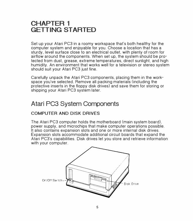
The Atari PC3 computer holds the motherboard (main system board). power supply, and microchips that make computer operations possible. It also contains expansion slots and one or more internal disk drives. Expansion slots accommodate additional ·circuit boards that expand the Atari PC3's capabilities. Disk drives let you store and retrieve information with your computer.
5
KEYBOARD. MONITOR. AND MOUSE
The Atari PC3 keyboard and monitor are the tools you and the computer use to communicate. You use the keyboard to give data and instructions to the Atari PC3. The monitor provides a visual display of your keyboard input and the Atari PC3's computing processes as they happen'. You can attach a monochrome. color. or EGA (Enhanced Graphics Adapter) monitor to your Atari PC3.
The mouse connects to the Atari PC3 and is used to operate the computer from GEM Desktop and certain applications. You use the mouse by rolling it on a flat surface and pressing the mouse buttons.
NUMERIC DAT A PROCESSOR AND RAM CHIPS
Chip sockets inside your Atari PC3 can accept an optional numeric data processor (Intel 8087 chip) and additional RAM chips (for a system total of 640 kilobytes). See Appendix B for complete installation instructions.
OPTIONAL DEVICES
Adding options to your Atari PC3 expands its functionality and customizes it to your particular needs. You can add almost any option designed for an IBM PC XT computer or compatible to your Atari PC3.
Note: See Appendix c for general instructions on installing expansion boards and internal drives. See the manual supplied with the option for specific installation and operating instructions.
Expansion Boards
Five expansion slots in your Atari PC3 accommodate IBM PC XT-compatible expansion boards. You can add hard disk controller. network. modem, and other boards to your system by using these slots. The boards should be chosen and configured so as not to conflict with any features already present in the Atari PC3. (For more information. see Appendix c.)
6
Drives
The Atari PC3 has two internal drive bays which can accommodate any IBM PC XT-compatible drive. This includes floppy and hard disk drives as well as tape and removable data cartridge drives. You can set up almost any drive configuration you want in the drive bays. One of the drives will normally be a floppy drive. (See Appendix B for information.)
The Atari PC3 can support up to two external floppy drives. It can also support up to two hard disk drives installed either externally or internally in a drive bay, on the frame. or on an expansion board.
Parallel and Serial Devices
Your Atari PC3 has both a parallel and serial port on the back panel. Typically a printer is connected to the parallel port and a modem to the serial port. You can connect parallel and serial devices without changing or adding �nything to the inside of your computer.
Connecting the Atari PC3 System
Setting up your system follows this order:
1. Installing options such as extra RAM chips, numeric data processor.expansion boards, and internal drives.
2. Connecting the power cable.
3. Setting the monitor type selection switches.
4. Connecting the monitor.
5. Connecting the keyboard and mouse.
6. Connecting other external peripherals.
7
Remove the protective inserts from all floppy disk drives and make sure the computer is turned off (the power switch is on the front). Then follow these steps to set up your system:
1. If you are installing RAM chips, a numeric data processor. expansionboards. or internal drives, do so now. (For instructions on installingRAM chips and the numeric data processor. see Appendix B. Forinstructions on installing expansion boards and internal drives. seeAppendix c.)
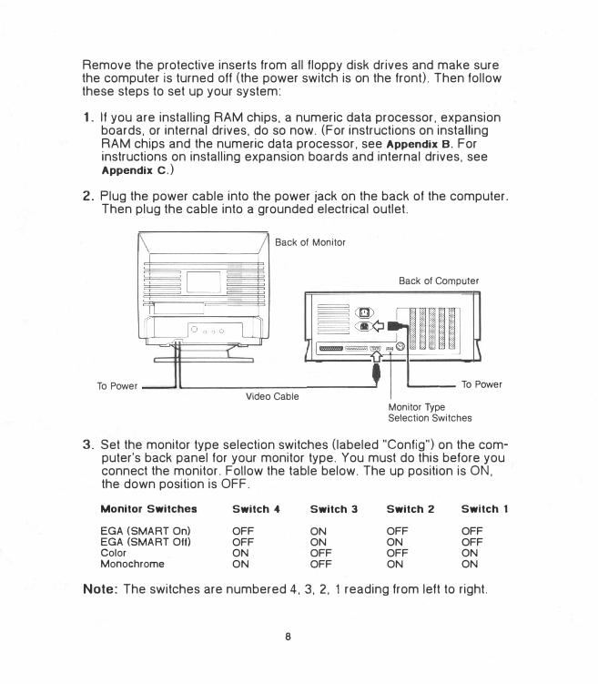
2. Plug the power cable into the power jack on the back of the computer.Then plug the cable into a grounded electrical outlet.
Back of Monitor
To Power Video Cable
Back of Computer
......_ __ To Power
Monitor Type Selection Switches
3. Set the monitor type selection switches (labeled "Config") on the computer's back panel for your monitor type. You must do this before youconnect the monitor. Follow the table below. The up position is ON.the down position is OFF.
Monitor Switches
EGA (SMART On) EGA (SMART Off) Color Monochrome
Switch 4
OFF
OFF
ON
ON
Switch 3
ON
ON
OFF
OFF
Switch 2
OFF
ON
OFF
ON
Switch 1
OFF
OFF
ON
ON
Note: The switches are numbered 4. 3. 2. 1 reading from left to right.
8
If you have installed a monochrome display adapter board in an expansion slot. the switches must be set to SMART Off. The HGC. MDA. and HCOLOR utilities then become meaningless.
Warning: To avoid damaging your monitor. you MUST set the switches correctly for your monitor type BEFORE you connect the monitor and switch on the system .
4. Set the monitor on top of or beside the computer. Plug the monitor'svideo cable into the port labeled "Video" on the back of the computer.Make sure the monitor is turned off. then connect its power cable tothe monitor. then to a grounded electrical outlet. (See the manualsupplied with your monitor for further information.)
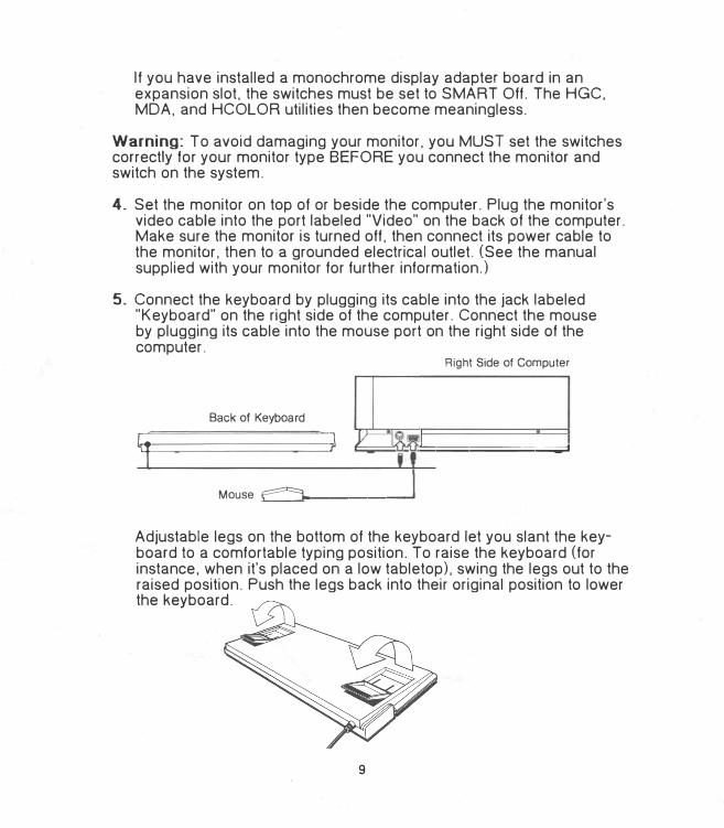
5. Connect the keyboard by plugging its cable into the jack labeled"Keyboard" on the right side of the computer. Connect the mouseby plugging its cable into the mouse port on the right side of thecomputer.
Right Side of Computer
Back of Keyboard
�l ) =I ======;;;;;;;;.;J
Mouse �L.. _______ ....,
Adjustable legs on the bottom of the keyboard let you slant the keyboard to a comfortable typing position. To raise the keyboard (for instance. when it's placed on a low tabletop), swing the legs out to the raised position. Push the legs back into their original position to lower the keyboard.
9
6. Connect external peripherals (such as a printer or modem) to theappropriate port on the computer's back panel. (See The Computer's
Back Panel later in this chapter.)
Switching the Atari PC3 System On and Ott
SWITCHING ON THE SYSTEM
Use MS-DOS Disk 1 (supplied with your system) when you switch on your Atari PC3. This disk contains data your computer needs in order to initialize.
Note: It's essential that you make backup copies of the disks supplied with your Atari PC3. For instructions, see Copying the Program Disks in Chapter 2.
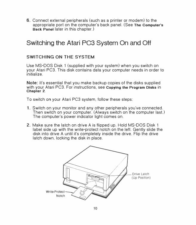
To switch OR your Atari PC3 system, follow these steps:
1. Switch on your monitor and any other peripherals you've connected.Then switch on your computer. (Always switch on the computer last.)The computer's power indicator light comes on.
2. Make sure the latch on drive A is flipped up. Hold MS-DOS Disk 1label side up with the write-protect notch on the left. Gently slide thedisk into drive A until it's completely inside the drive. Flip the drivelatch down. locking the disk in place.
Write-Protect_
Notch
10
3. The computer begins retrieving data from the disk. When the computer is finished. the operating system MS-DOS prompts you for thedate on the monitor screen:
Current date is Tue 1-01-1980Enter new date (mm-dd-yy):
Note: If the date prompt doesn't appear. check that your monitor is switched on with the brightness properly adjusted, and that MS-DOS Disk 1 is correctly inserted with the drive latch flipped down. If you still don't see a date prompt, switch off the system and make sure all cable connections are correct and secure. If the problem continues when you switch on the system. see Appendix A.
4. Press the [Enter] key. MS-DOS responds by prompting you for thetime:
Current time is 0:01:15:24Enter new time:
5. Enter the hour and minutes (and seconds. if you like). separating themwith colons(:). MS-DOS uses a 24-hour clock. so add 12 to any PMhour. For example, if the time is 3:20 PM. type 15:20:00.
6. Press the [Enter] key. Your screen displays something like this:
Current date is Tue 1-01-1980Enter new date (mm-dd-yy): 3-30-88Current time is 0:01:15:40Enter new time: 15:20:00
Microsoft® MS-DOS® Version 3© Copyright Microsoft Corp 1981-1987
A>
Note: MS-DOS adds the date and time to all files you create or modify to help you identify the most up-to-date versions of your files. Once you set the real-time clock (see Chapter 2), you can skip over the prompts by pressing [Enter] twice.
11
The A> at the bottom of the display is the MS-DOS system prompt. The A means that drive A is the current default drive. Next to the prompt is a blinking bar called the cursor. The system prompt and the cursor tell you that MS-DOS and the Atari PC3 are ready to receive instructions. The line containing the prompt is called the MS-DOS command line.
Note: Chapters 2 and 3 and the MS-DOS User's Reference tell you how to work with MS-DOS and your Atari PC3.
When switched on. the Atari PC3 automatically runs in turbo mode unless you've installed a numeric data processor (8087 chip). When turbo mode is on. its indicator light (labeled "CPU") on the front of the computer is lit.
If you have installed a numeric data processor. the Atari PC3 defaults to standard PC mode when switched on. If your 8087 chip is rated at 5 MHz. you must stay in PC mode. If your 8087 chip is rated at 8 MHz or faster (8087-2 or 8087-1), you can enable turbo mode after switching on your,Atari PC3. (For more information. see Changing System Speed in Chapter 2.)
Startup Drive Choices
Depending on the drives you have installed, you can start up your system from the first hard disk (drive 0) or floppy drives A. B. or .C.
To start up from drive 0, make sure your hard disk is prepared as described in Appendix E. Then flip up (open) all floppy disk drive latches and switch on your system.
To start up from floppy drive A. follow the instructions iri Switching On the System in this chapter. To start up from floppy drive B or C. follow these instructions:
1. Switch on your system and insert MS-DOS Disk 1 into the drive youwant to use as the startup drive.
2. As soon as the screen text appears. press [F2) to start up from drive Bor [F3J to start up from drive C. After the system initializes, the letter ofthe startup drive appears in the MS-DOS prompt.
12
SWITCHING OFF THE SYSTEM
To switch off your system. remove all disks from your floppy drives. Switch off your computer first. then your monitor and any peripherals. Wait at least ten seconds before switching your computer system back on. (Switching the computer on with the on/off switch is called a coldstart. and it completely initializes the computer.)
Ports and Features
KEYBOARD
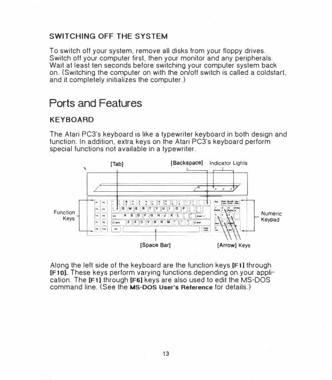
The Atari PC3's keyboard is like a typewriter keyboard in both design and function. In addition. extra keys on the Atari PC3's keyboard perform special functions not available in a typewriter.
Function Keys
[Backspace] Indicator Lights[Tab]
'���--+-��������==:::::+--+=:::::::=:::::+��
[Space Bar] [Arrow] Keys
Numeric Keypad
Along the left side of the keyboard are the function keys [F1] through [F1 OJ. These keys perform varying functions depending on your application. The [F1] through [F6] keys are also used to edit the MS-DOS command line. (See the MS-DOS User's Reference for details.)
13
The alphanumeric keys (letters. numbers. and symbols) are primarily used to enter data and commands. They usually function just like similar keys on a typewriter. The [Shift]. [Tab]. [Backspace]. and [Caps Lock) keys also perform the same functions as their typewriter counterparts. Most alphanumeric keys automatically repeat when they are held down.
Certain keys have special control functions. These keys are [Alt]. [Ctrll. [Dell. [End), [Esc). [Home). [Ins). [Num Lock). [Pg Dn). [Pg Up). [Prtsc). and [Scroll Lock). Although the functions of these keys can vary depending on your application. the following key combinations (keys pressed simultaneously) are usually in effect:
[Ctrl) [SJ Stops the screen display from scrolling. Press [Ctrl) [SJ again to resume scrolling.
[Ctrl) [Num Lock) Pauses the output of the current program or command. Press any key to continue.
[Ctrl) [Scrol\ Lock) Stops the output of the current program or command and returns you to the MS-DOS command line.
[Clrl) [Alt) [Del) Restarts (warmstarts) your system.
[Ctrl) [Alt) [keypad + J Turns on turbo mode, setting the system to high speed.
[Ctrl) [Alt) [keypad -) Turns off turbo mode, returning the system to normal PC computing speed.
[Ctrl) [Alt) [<) Turns on audible key click.
[Ctrl) [Alt) [>) Turns off audible key click.
When a printer is connected to your system. you can also use these key combinations:
[Shill) [PrtSc)
[Ctrl) [PrtSc)
Prints the screen display.
Prints what you type as you type it. Also prints the screen output (the Atari PC3's screen response to your instructions). Press [Ctrl) [PrtSc) again to stop printing.
14
The four [Arrow] keys are generally used within an application to move the cursor in the direction of their arrow (up, down. left. or right). The cursor is a movable symbol on screen that marks where the next action will take place.
The numeric keypad lets you type numbers and math symbols in calculator style. Pressing [Num Lock] once sets the keypad to numeric entry. Pressing [Num Lock] again lets you use the keys for the symbols as marked. and for specific functions depending on your application. When [Num Lock] is pressed for numeric entry. its indicator light is lit.
Indicator lights for [Num Lock]. [Scroll Lock]. and [Caps Lock]. when lit. tell you that those functions are active. (However. if your application internally sets [Caps Lock], then its indicator light will not be lit.)
Note: The [Sys Req] key normally has no function.
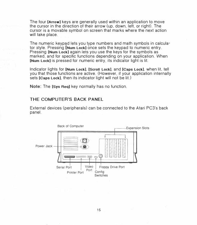
THE COMPUTER'S BACK PANEL
External devices (peripherals) can be connected to the Atari PC3's back panel.
Back of Computer
Power Jack
Serial Port
Printer Port
Floppy Drive Port
Con fig Switches
15
Expansion Slots
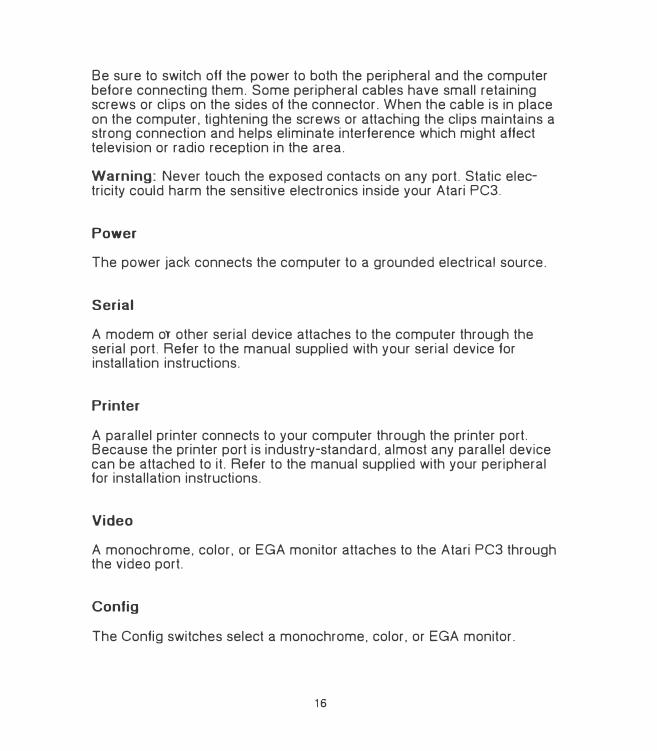
Be sure to switch off the power to both the peripheral and the computer before connecting them. Some peripheral cables have small retaining screws or clips on the sides of the connector. When the cable is in place on the computer. tightening the screws or attaching the clips maintains a strong connection and helps eliminate interference which might affect television or radio reception in the area.
Warning: Never touch the exposed contacts on any port. Static electricity could harm the sensitive electronics inside your Atari PC3.
Power
The power jack connects the computer to a grounded electrical source.
Serial
A modem or other serial device attaches to the computer through the serial port. Refer to the manual supplied with your serial device for installation instructions.
Printer
A parallel printer connects to your computer through the printer port. Because the printer port is industry-standard. almost any parallel device can be attached to it. Refer to the manual supplied with your peripheral for installation instructions.
Video
A monochrome. color. or EGA monitor attaches to the Atari PC3 through the video port.
Config
The Config switches select a monochrome. color. or EGA monitor.
16
Floppy Disk Drive
Up to two external floppy disk drives can connect to the Atari PC3 through the floppy disk drive port. You can connect an Atari PCF554 (5V4-inch) drive. an Atari SF314 (3V2-inch) drive. or one of each.
Expansion Slots
If optional expansion boards with connectors have been installed on the Atari PC3, the connectors are accessed through these slots.
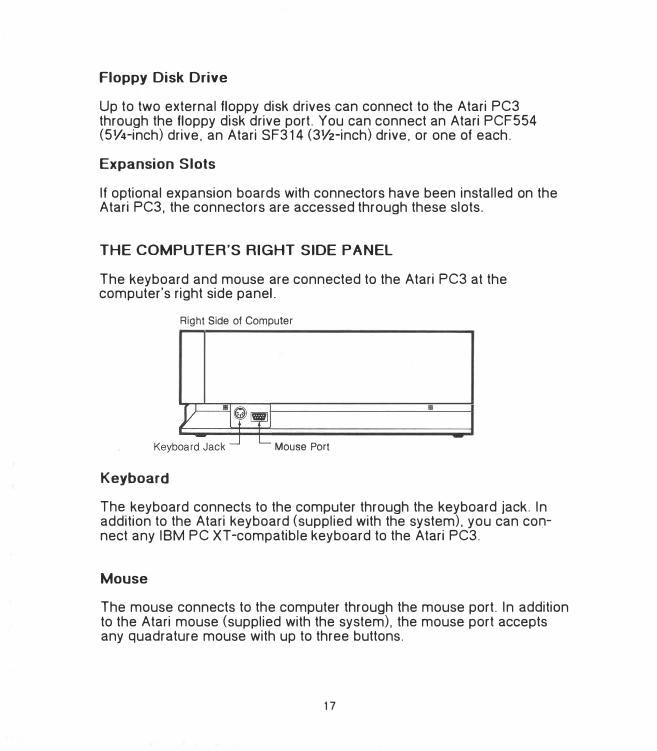
THE COMPUTER'S RIGHT SIDE PANEL
The keyboard and mouse are connected to the Atari PC3 at the computer's right side panel.
Right Side of Computer
Mouse Port
Keyboard
The keyboard connects to the computer through the keyboard jack. In addition to the Atari keyboard (supplied with the system). you can cor:inect any IBM PC XT-compatible keyboard to the Atari PC3.
Mouse
The mouse connects to the computer through the mouse port. In addition to the Atari mouse (supplied with the system). the mouse port accepts any quadrature mouse with up to three buttons.
17
CHAPTER2 AT ARI PC3 SYSTEM OVERVIEW
MS-DOS
MS-DOS (Microsoft Disk Operating System) is the operating system for the Atari PC3, and is contained on MS-DOS Disks 1 and 2 supplied with your computer.
MS-DOS consists of a group of programs that manage all computer processes such as running applications. creating files, and printing documents. You control MS-DOS by entering commands on the MS-DOS command line next to the MS-DOS prompt. (Controlling MS-DOS with commands is fully explained in Chapter 3 and in the MS-DOS User's Reference.)
One Drive and Multi-Drive Systems
Your Atari PC3 has at least one internal floppy disk drive that uses 5V4-inch floppy disks. To streamline data storage and retrieval, you can also connect an additional floppy disk drive that uses either 5V4-inch or 3V2-inch disks. In addition, you can install a hard disk drive (see Appendix c and Appendix D).
In systems limited to one drive. that drive acts as both drive A and drive B. This allows for operations that use two disks. such as copying a filefrom one disk to another. During such operations. the disks themselvesare referred to as disk A and disk B. and MS-DOS prompts you when toswitch disks in the drive in order to proceed.
19
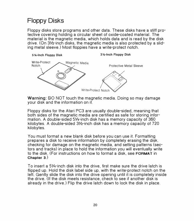
Fl�ppy Disks
Floppy disks store programs and other data. These disks have a stiff protective covering holding a circular sheet of oxide-coated material. The material is the magnetic media. which holds data and is read by the disk drive. (On 3V2-inch disks. the magnetic media is also protected by a sliding metal sleeve.) Most floppies have a write-protect notch.
51/4·lnch Floppy Disk
Write-Protect
Notch
\
31/2-lnch Floppy Disk
Protective Metal Sleeve
Warning: 6>0 NOT touch the magnetic media. Doing so may damage your disk and the information on it.
Floppy disks for the Atari PC3 are usually double-sided. meaning that both sides of the magnetic media are certified as safe for storing information. A double-sided SV4-inch disk has a memory capacity of 360 kilobytes. A double-sided 3V2-inch disk has a memory capacity of 720 kilobytes.
You must format a new blank disk before you can use it. Formatting prepares a disk to receive information by completely erasing the disk. checking for damage on the magnetic media, and setting patterns (sectors and tracks) in place to hold the information you will eventually write to the disk. (For instructions on how to format a disk. see FORMAT in Chapter 3.)
To insert a 5V4-inch disk into the drive. first make sure the drive latch is flipped up. Hold the disk label side up, with the write-protect notch on the left. Gently slide the disk into the drive opening until it is completely inside the drive. (If the disk meets resistance. check to see if another disk is already in the drive.) Flip the drive latch down to lock the disk in place.
20
To remove the disk. flip the drive latch up and gently pull out the disk.
To insert or remove a 3V2-inch disk. follow the instructions supplied with the drive.
Warning: To avoid damaging your disks. make sure the drive's busy light is off before you insert or remove a disk.
WRITE-PROTECTING DISKS
When you write to a disk. the drive and computer work together to put information from RAM onto the disk. where it is stored. Write-protecting a disk is a security measure you take to prevent new information from being written to the disk. This keeps you from inadvertently changing disk contents you want to preserve.
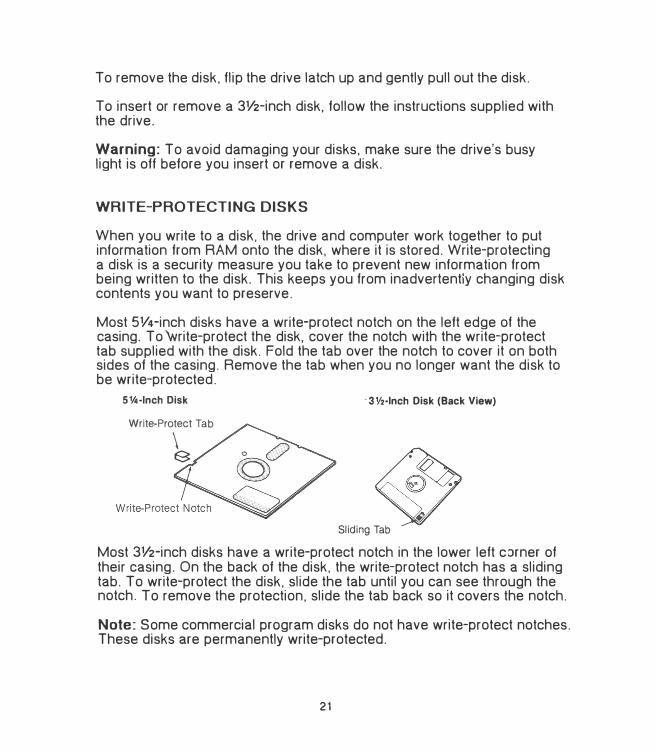
Most 5V4-inch disks have a write-protect notch on the left edge of the casing. To write-protect the disk. cover the notch with the write-protect tab supplied with the disk. Fold the tab over the notch to cover it on both sides of the casing. Remove the tab when you no longer want the disk to be write-protected.
5Y4·1nch Disk
Write-Protect Tab
\ E3
· 3Y2-lnch Disk (Back View)
Sliding Tab
Most 3V2-inch disks have a write-protect notch in the lower left corner of their casing. On the back of the disk. the write-protect notch has a sliding tab. To write-protect the disk. slide the tab until you can see through the notch. To remove the protection. slide the tab back so it covers the notch.
Note: Some commercial program disks do not have write-protect notches. These disks are permanently write-protected.
21
Copying the Program Disks
You must make backup copies of all disks supplied with your Atari PC3 before beginning to work with them routinely. This protects you from losing information if you lose or damage the disks. After copying, store the. original disks in a safe place protected from dust, grease, extreme temperatures, and sources of electric power or magnetism. Always use the copies as your working disks.
MS-DOS provides a DISKCOPY command for copying an original disk to a blank disk. If the blank disk is not formatted, DISKCOPY formats it before copying. To use DISKCOPY. follow these steps:
1. Have a blank disk ready for each disk you're going to copy. Do notwrite-protect the blank disks.
2. Switch on your system as described in Chapter 1 to display the A>prompt
3. Type
DISK COPY
then press [Enter].
4. MS-DOS will ask you for the source disk. Leave the original MS-DOSDisk 1 in the drive and press any key.
5. Next, MS-DOS will ask for the target disk. Replace the source diskwith a blank disk and press any key. You may be asked to swap thesource and target disks several times.
6. When formatting and copying are complete, MS-DOS will ask if youwant to copy another disk. Press [YJ.
7. When MS-DOS asks for the new source disk, remove the disk fromdrive A, replace it with the next disk you want to copy, and press anykey. Then repeat steps 5, 6, and 7 until all original disks are copied.
8. When MS-DOS asks if you want to copy another disk, press [NJ.
22
Note: For more information. see DISKCOPY in Chapter 3.
After removing each backup disk from the drive. immediately label it using the same name as on the original disk's label. Write on the label before affixing it to the disk. or if the label is already on the disk. write with a felt-tipped pen. (Writing on the disk with a hard-tipped pen or pencil can harm the media.) Store the original disks and always use the copies as your working disks.
The CONFIG.SYS and AUTOEXEC.BAT Files
After you switch on the computer and before MS-DOS displays the A> prompt. the system goes through its initialization process. During initialization. MS-DOS is installed. CONFIG.SYS and AUTOEXEC.BA T are two special files you can create to customize your MS-DOS installation. MS-DOS will read these files during initialization.
Newly created or modified CONFIG.SYS and AUTOEXEC.BAT files take effect after you restart the Atari PC3. To create the files. see the following two sections. To modify an existing file. use a text editor such as MS-DOS EDLIN (described in the MS-DOS User's Reference).
THE CONFIG.SYS FILE
The CONFIG.SYS file tells MS-DOS how to use certain devices. To create CONFIG.SYS. type the following at the A> prompt:
COPY CON CONFIG.SYS [Enter) DEVICE = ANSI.SYS [Enter) [F6) [Enter)
The first line creates and names the file. The second line enables an
ANSI standard terminal emulation. required by many applications. The third line ends the file and allows it to be saved to disk.
Note: CONFIG.SYS can also be used to configure the Atari PC3 to handle nonstandard floppy disk drives. create a RAM disk, and customize some MS-DOS performance parameters. For complete information. see the MS-DOS User's Reference.
23
THE AUTOEXEC.BA T FILE
The AUTOEXEC.BA T file tells MS-DOS what commands to automatically execute during system initialization. This saves you the work of entering routine commands after switching on your computer. To create an AUTOEXEC.BAT file. type the following at the A> prompt:
COPY CON AUTOEXEC.BAT [Enter)
This line creates and names the file. Now you can add commands to the file by typing each command on a separate line and pressing [Enter). For example. the line
DIR [Enter)
displays a list of files in the current directory every time you start up your system. Other useful commands to add to the AUTOEXEC.BA T file are CHKDSK. PATH. CHOIR. and commands for executing specific applications. (For r-QOre information on these commands. see Chapter 3 and the MS-DOS User's Reference.)
When your AUTOEXEC.BA T file contains the lines you want. press [F6J [Enter). This ends the file and allows it to be saved to disk.
You can make other .BAr (batch) files to run often-used commands. To do that. create a .BAT file consisting of the sequence of commands you want to run as a group. Then run the commands by entering the first part of the filename (without the .BAT extension) at the prompt.
For example. you may find that you often print the same groups of files from different directories, each time typing separate PRINT commands for each group, like this:
PRINT \TABLES\*.OAK [Enter) PRINT \PA YROLL\TEMP\*.CHK [Enter) PRINT \ADS\RADIO\WKEND.TXT [Enter)
24
An easier way to print the groups of files is to add the three command lines to a batch file named. for example. P.BAT. When you want to print the files. simply type P (the filename without the .BAT extension) and press [Enter].
Note: Refer to the MS-DOS User's Reference for more information on AUTOEXEC.BAT and batch files in general.
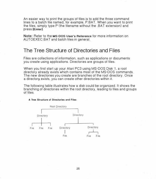
The Tree Structure of Directories and Files
Files are collections of information. such as applications or documents you create using applications. Directories are groups of files.
When you first start up your Atari PC3 using MS-DOS Disk 1, a root .directory already exists which contains most of the MS-DOS commands. The new directories you create are branches of the root directory. Once a director� exists. you can create other directories within it.
The following table illustrates how a disk could be organized. It shows the branching of directories within the root directory. leading to files and groups of files.
A Tree Structure of Directories and Files
Root Directory
Directory Directory
I I File File File Directory
I File
25
I
Directory
r-1--i File File
Filenames
Files and directories are identified by their filenames. When you create a file or directory. you must name it in order to save it and to list and identify it later. Filenames are used along with commands to send instructions to MS-DOS.
A filename has two parts: the name and the extension.
SAMPLE.EXE
I _extension (optional; up to three characters)
name (mandatory; up to eight characters)
A name can have up to eight characters (letters. symbols. or numbers). An extension is optional and can have up to three characters. (Directories do not usually have extensions.) A period always divides the extension from the name. The following characters CANNOT be used in a name or extension:
."/\[]:I<> +=:.•?
In addition. the names and extensions listed below are reserved by MS-DOS for special purposes and can only be used for those purposes:
Names Extensions
AUX LPT1 .APP
COM1 LPT2 .BAT
COM2 LPT3 .COM
COM3 NUL .EXE
CON PAN .SYS
Names can be clues to the specific information in the file. such as TAXES for tax information. or T AXES85. T AXES86. T AXES87 for a series of tax information files. Extensions often indicate the type of a file. For example . . TXT may indicate a document file created with a word processor.
26
In many cases you can specify a set of filenames by using two special characters called wildcards: the asterisk(*) and the question mark(?). Wildcards are used when you want to perform the same operation. such as copying or deleting, on a group of files.
An asterisk in a filename stands for all characters and combinations of characters. and can replace an entire name or extension. For example. the wildcard designation
••
means all filenames. A filename can often have an asterisk as the name while spelling out the extension. For example.
•.DOC
means all filenames with the .DOC extension. such as
LETT�R.DOC . ATARI.DOC
MOM.DOC
but not
FRANCE.TXT
The asterisk must be the last character in the name or extension. For example,
TAX*.BAS
is valid. but
T*X.BAS
is not.
27
The question mark in a filename stands for all single characters. For example,
MOM?.LET
means all files that begin with MOM. have any character in the fourth position of the name. and have the extension .LET. such as
MOM1.LET MOM4.LET MOMZ.LET
but not
-JACK.LETMOM33.LETMOM1.DOC
Note: Not all commands or programs can accept filenames specified with wildcardf For more information, see the MS-DOS User's Reference
or the documentation supplied with your application.
Changing the Drive Designation
Sometimes you'll need to change the drive designation in the MS-DOS command line, depending on the drive you want to access.
If you have a one-drive system. that drive can act as both drive A and drive B. To change the drive designation. type the following at the A>prompt:
-
B: [Enter]
MS-DOS responds by asking you to "Insert a new disk for drive B: and strike Enter when ready." Replace the disk in drive A with the one you want to use for drive B and press [Enter]. The MS-DOS prompt is redisplayed as B >.
28
To restore drive A as the working drive. type
A: [Enter]
at the prompt.
Swap disks when MS-DOS asks you to. then press [Enter]. The MS-DOS prompt reappears as A>.
If you have a multi-drive system. you can make any drive on your system the working drive. At the MS-DOS prompt, type the name of the drive followed by a colon. Then press [Enter]. For example. to set drive C as the working drive. type
C: [Enter]
The MS-DOS prompt is redisplayed as C >.
If you try to set a nonexistent drive as the working drive. you'll get an error message.
Atari PC3 Special Features
SETTING THE REAL-TIME CLOCK
A clock battery in your system runs a real-time clock that keeps the correct time even when your system is switched off. Once the clock is set. you can skip the MS-DOS date and time prompts when you start up your system. To set the clock, start your system and enter the correct date and time when the prompts appear.
29
If your system is already started. you can get the date prompt by typing
DATE [Enter]
and the time prompt by typing
TIME [Enter]
Then type
RTC [Enter]
The RTC utility sets the real-time clock to the current MS-DOS time. To reset the clock. follow the same procedure.
Note: The lithium battery pack inside the Atari PC3 can be replaced when it runs down. Buy a fresh battery pack of the same type. Then remove the cover from the Atari PC3 (see Appendix e), disconnect the battery wire. and detach the old battery pack from its Velcro strip. Mount the new battery pack on the same strip and reconnect the battery wire.
CHANGING SYSTEM SPEED
The Atari PC3 can process information in either PC mode or turbo mode. PC mode runs at 4.77 MHz: turbo mode runs at 8.0 MHz. In turbo mode, the Atari PC3 performs operations such as arithmetic calculation. graphics generation, and saving and retrieving information more quickly.
When switched on. the Atari PC3 automatically runs in turbo mode unless you've installed a numeric data processor (8087 chip). When turbo mode is on. its indicator light (labeled "CPU") on the front of the computer is lit.
If you have installed a numeric data processor. the Atari PC3 defaults to standard PC mode when switched on. If your 8087 chip is rated at 5 MHz. you must stay in PC mode. If your 8087 chip is rated at 8 MHz or faster (8087-2 or 8087-1), you can enable turbo mode after switching on your Atari PC3.
30
GEM Desktop, GEM Write. and GEM Paint (as well as many other programs) can run in turbo mode. Other programs, such as games or copyprotected software, r:nay run only in PC mode. Some applications will require a specific mode; other applications will let you choose the mode you prefer. In those cases. you may have to experiment to find which mode works best with a particular application.
To enable turbo mode, type the command
TURBO ON [Enter]
or use the key combination
[Ctrl] [Alt] (1]
or
[ Ctrl] [Alt] [keypad +]
To disable the mode, type the command
TURBO OFF [Enter]
or use the key combination
[Ctrl] [Alt] [2]
or
[Ctrl] [Alt] [keypad -]
If you've installed a fast (8 MHz or faster) numeric data processor in your PC3, you can run turbo mode automatically when you start up your system by adding the command TURBO ON to your AUTOEXEC.BA T file.
31
SELECTING MONITOR DISPLAY MODES
Your Atari PC3 includes a video display subsystem and video display commands that let you select a screen resolution and colors (display modes) according to your monitor type and software. Generally, modes with higher resolution offer fewer colors. and modes with lower resolution offer more color selections.
To set your display mode. first determine what monitor type (color, monochrome. or enhanced display) you have connected to your system. Then refer to Monitor Display Mode Commands in Chapter 3 for information on display modes allowed by each monitor type and the screen resolution and colors available with each mode.
Wben selecting software to run on your Atari PC3, check whether the program can be operated in a display mode available to you. For example, some programs can operate in EGA mode only,.so you won't be able to use them with an MDA-type monochrome monitor.
Note: The Afari PCM 124 monitor is an enhanced display (EGA) monitor that you can use with all PC3 display modes.
SETTING THE KEY CLICK FEATURE
The Atari PC3's key click feature provides an audible response (key click) as you type. To turn on the feature. type the command
CLICK ON [Enter]
or use the key combination
[Ctrl] [Alt] [<]
To turn off key click. type the command
CLICK OFF [Enter] '·
or use the key combination
[Ctrl] [Alt] [>]
32
INST ALLING THE MOUSE FOR USE
WITH NON-GEM PROGRAMS
Installing a mouse driver file (MOUSE.COM or MOUSE.SYS) lets you use the mouse in other applications besides GEM Desktop. To install the mouse. insert your GEM Startup disk in your working drive and type the command
MOUSE [Enter]
You can also install the mouse by copying the MOUSE. COM file to your startup disk. Then enter the command MOUSE in your AUTOEXEC.BA T file or enter DEVICE= MOUSE.SYS in your CONFIG.SYS file.
33
CHAPTER3
INTRODUCTION TO MS-DOS COMMANDS
Commands
Commands are instructions to MS-DOS. They are typed next to the system prompt and activated by pressing [Enter]. (Typing a command and pressing [Enter] is called entering the command.) Commands can be entered in uppercase or lowercase letters and must be spelled correctly.
The later sections of this chapter describe the most often used MS-DOS commands. You can practice with the examples or use this chapter as a reference for specific commands. To practice. make sure you have a copy of MS-DOS Disk 1 in drive A. and that it is not write-protected. The A> prompt should be displayed on screen and you should be in the rootdirectory of the disk. If you're not sure you're in the root directory. enter
CD\
This command puts you in the root directory. (A backslash alone designates the root directory.)
Note: For complete information on MS-DOS commands. see the MS-DOS User's Reference.
PARAMETERS
Some commands are entered alone. Other commands are entered with further instructions. called parameters. which are either optional or required in order to complete the command.
35
Pathnames
Parameters can tell MS-DOS where to find information by directing it to particular drives, directories. and files. When a drive. directories. and filename are included as parameters, they are listed in a specific order and separated from each other by backslashes(\). The drive is listed first, followed by the directory or directories. The filename is always listed last. This type of listing is called a pathname. For example,
A:\MAILBAG\JUL Y87\LETTER. TXT
is a pathname. A: means the disk in drive A; the first backslash designates the root directory; MAILBAG is a directory in the root directory; JUL Y87 is a directory in MAILBAG; and LETTER.TXT is a file in JUL Y87. All items in the pathname are separated from each other by backslashes.
Pathnames can be either absolute or relative. Absolute pathnames begin at the root directory with a backslash. For example.
'\
\ADS\RADIO\WKEND. TXT
specifies the pathname from the root directory (in the working drive) through two directories to the filename. A relative pathname begins with a directory name or filename within the current directory in the specified drive. For example, if you are in the directory ADS, then the pathname
RADIO\WKEND. TXT
is a relative pathname referring to the file WKEND.TXT in the directory RADIO in your current directory ADS.
In a pathname. a period(.) can indicate the current directory, and two periods (..) can indicate the parent directory of the current directory. The periods offer a useful shorthand when you want to return to the parent directory and branch off in another direction. For example, the parent directory might be named ADS. and it might hold two directories named RADIO and TV. If you're in the RADIO directory, you can move to the TV directory by entering
.. \TV
36
Switch Parameters
Certain special parameters. called switch parameters or switches. control how MS-DOS performs the command. Switch parameters always begin with a forward slash(/). For example. when the DIR command (which lists the files in a directory) is entered with its switch parameter /w. the screen output is displayed in a wide format (five columns of information) instead of the default narrow format (one column of information).
COMMAND SYNTAX
The syntax of each command tells you what parameters and switches can be used with the command and whether or not they are required. Each command description in this chapter shows the command's syntax including its most often used switches.
Certain characters are used in the command syntax descriptions to separate and describe the parameters. These characters are indicators only and are not typed with the parameter. The characters and their uses in syntax description are listed below:
Character
[ 1 < >
Name
Square brackets Angle brackets Ellipsis
Use
Indicates optional parameters. Indicates needed information. Indicates an item can be repeated.
An example of syntax follows. It shows the syntax for the command DIR and gives an explanation of its parameters:
Syntax: DIR [<drive:>] [<pathname>] [/p] [/w]
Example: DIR A:\MAILBAG\JUL Y87/p/w
Parameter Explanation
[<drive:>] The square brackets indicate that the drive parameter is optional. Use ii only if you want to access a drive other than the working drive (given in the MS-DOS prompt). The angle brackets indicate that you must enter a valid drive designation (a drive letter followed by a colon, such as A:, 8:, or C:).
37
Parameter
[<pathname> J
[/p]
[/w]
Explanation
The square brackets indicate that the pathname parameter is optional. Use it to list directories and filenames. Items listed in the pathname must be separated by backslashes (\).
The /p (pause) switch is optional. It tells MS-DOS to display the directory one screenlul at a time, pausing between displays. If the switch is omitted and the directory is longer than one screenlul, it will scroll up off-screen as it is displayed.
The /w (wide) switch is optional. It tells MS-DOS to display the directory in a five-column format, rather than the default format of one column.
Follow these guidelines for ent'ering commands and parameters correctly:
• Include all required punctuation characters. Drive letters must be followed by a colon (for example, A:), and a backslash(\) must separateall items in a pathname from each other.
• Commands and parameters can be entered in any combination ofuppercase and lowercase letters. For example, diR/P is just as validas DIR/p.
• A space must always separate the command from the drive parameter.DIR B: is valid; DIRB: is not.
• A space between the command and any parameter other than the driveparameter is optional. For example, DIR/p and DIR /p are both valid.
·-Spaces between a series of parameters are optional. For example.DIR/w/p and DIR /w /p are both valid.
• The order of switches is usually not important. For example, DIR/w/pand DIR/p/w are both valid.
• A command and its parameters together can have a maximum of 126characters and spaces.
38
EDITING COMMANDS
To edit a command line before pressing [Enter]. use the[<--] ([Backspace]) key to erase characters to the left of the cursor. then retype. To erase the entire command, press [Esc].
If you enter a misspelled command or a command with incorrect syntax. MS-DOS displays a message telling you that it is unable to interpret the command. The usual solution is to re-enter the command (although you can also edit it with the MS-DOS editing keys described in the MS-DOS User's Reference).
Preparing Floppy Disks
FORMAT
The FORM('. T command prepares a new disk to receive information by dividing it into the tracks and sectors where information will be stored. At the sa.me time, it can optionally copy the MS-DOS system files to the newly formatted disk so you can use it as your startup disk.
Warning: FORMAT erases all data on a disk. If the disk you are about to format contains files you want to save. use the COPY command to copy them to another disk before proceeding.
Syntax: FORMAT <drive:> [/v] [/s]
Example: FORMAT A:/v/s
The switch parameter /v (volume name) lets you enter a name for the disk. The switch parameter /s (system files) copies the system files to the newly formatted disk so you can use it as your startup disk.
To format a disk and copy the system files to it. follow these steps:
1. With MS-DOS Disk 1 in drive A. switch on your system as explainedin Chapter 1. At the MS-DOS prompt, enter
FORMAT A:/s
39
2. When prompted. remove the startup disk and insert the disk to beformatted. Press [Enter].
3. MS-DOS displays its progress as it formats the disk. tells you whenformatting is complete. and then writes the system files to the disk.
4. When copying is complete, MS-DOS displays the amount of storageavailable on the disk plus any space used _by system files or areas thatwere found to be defective (and mapped out of the available space).Then MS-DOS asks if you want to format another disk. Enter [YJ toformat another disk. or [NJ to return to the system prompt.
Note: When used with double-sided drives available for the Atari PC2. FORMAT will automatically format disks as double-sided.
You can use FORMAT to erase an entire disk all at once rather than individually erasing each item on the disk with the DEL and RMDIR commands.
Copying Disks
DISK COPY
The DISKCOPY command copies the entire contents of one disk (the· source disk) to another disk (the target disk). If the target disk has not been formatted. DISKCOPY formats it before copying.
Syntax: DISKCOPY [<source drive:>) [<target drive:>)
Example: DISKCOPY A: B:
Warning: DISKCOPY erases all information previously recorded on the target disk. If the target disk contains files you want to keep,- copy them (using COPY) to another disk before using DISKCOPY.
40
To copy disks with DISKCOPY. follow these steps:
1. Insert the source disk (the disk to be copied) into drive A. Have a target disk (the disk to be copied to) ready for each disk you're going tocopy. Do not write-protect the disks.
2. If you have one drive, enter
DISK COPY
If you have two drives. enter
DISKCOPY A: 8:
3. MS-DOS will ask for the source disk. Leave the disk to be copied inthe drive and press any key.
4. Next. MS-DOS will ask for the target disk. If you have one drive.remove the source disk and replace it with the target disk. thenpress an'y key. You may be asked to swap the source and targetdisks several times.
If you have two drives, insert the target disk into drive B and pressany key.
5. When formatting and copying are complete. MS-DOS will ask if youwant to copy another disk. If you do. press [YJ. When MS-DOS asksfor the source disk. remove the disk from drive A. replace it with thenext disk you want to copy. and press any key. Then repeat step 4.
If you do not want to copy another disk. press [NJ.
Note: The target disk must have the same (or larger) storage capacity as the source disk in order for you to successfully copy data from disk to disk using DISKCOPY.
41
Copying Files
COPY
The COPY command lets you copy files from one directory to another on the same disk or from a source disk to a target disk.
Copying a File to a Directory
You can use COPY to duplicate a file from the root directory to an existing directory on the same disk.
Syntax: COPY <pathname> <directory> COPY <pathname> <pathname>
Example: COPY \LETTER.TXT MAILBAG
For examRle. you might have a directory named MAILBAG on the disk in your working drive. To copy the file LETTER.TXT from the root directory to the MAILBAG directory, enter:
COPY \LETTER. TXT MAILBAG
Notice that the source and destination pathnames must be separated by a space. If no destination pathname is specified. the current directory is assumed.
To copy a group of files at once. use wildcards in the source pathname (for example, L *.TXT).
Copying Files from Disk to Disk
You can use COPY to copy files from a source disk to a target disk.
Syntax: COPY <drive:> <pathname> <drive:> [<pathname>]
Example: COPY A:LETTER.TXT 8:\LEGAL
42
To copy the file LETTER.TXT from one disk to the root directory of another disk. follow the steps in one of the two next sections. One-Drive
System and Multi-Drive System.
ONE-DRIVE SYSTEM
1. If you have one drive. make sure the source disk (the disk containingthe file) is in the drive. Enter
COPY A:LETTER. TXT B:
2. When MS-DOS asks you for disk B. remove the source disk and inserta formatted target 1sk (the disk you want to copy the file to) into thedrive. Then press any key. You may be asked to swap the source andtarget disks several times during copying.
MUL Tl-DRIVE SYSTEM
1. If you have more than one drive. insert the source disk (the disk containing the file) into drive A. Insert the target disk (the disk you want tocopy the file to) into drive B.
2. Enter
COPY A:LETTER. TXT B:
When copying is finished, MS-DOS tells you how many files were copied.
To copy a group of files at once. use wildcards in the source pathname (for example. L *.TXT) and specify a destination pathname. (If no destination pathname is specified, the current directory is assumed.)
43
Viewing, Renaming, and Erasing Files
TY.PE
The TYPE command displays file contents for you to review. You cannot edit a file displayed with the TYPE command.
Syntax: TYPE <pathname>
Example: TYPE LETTER.TXT
Entering the example given displays the file LETTER.TXT in the root directory of the working drive.
When you use TYPE to display a file larger than one screen, the file will scroll up as it is displayed. To freeze a screen. press [Ctrl] [Num Lock] or [Ctrl] [S]. Press [Space Bar] to resume the display.
REN (RENAME)
The REN command changes the name of one or more files.
Syntax: REN <pathname> <new filename>
Example: REN LETTER.TXT RESUME.DOC
The example changes the filename LETTER.TXT to RESUME.DOC. Notice that the pathname and new filename parameters must be separated by a space.
You cannot rename a file with a filename that already exists in the same directory. If you try to do so. MS-DOS tells you that a file with that filename already exists.
44
To rename a group of files at once. use wildcards in the pathname and new filename. For example. to rename
to
TAXTEXT.85 TAXTEXT.86 TAXTEXT.87
IRSTEXT.85 IRSTEXT.86 IRSTEXT.87
enter
REN TAXTEXT.* IRS*.*
Note: REN does not rename directories. If you want a directory to have a new name. you can create a new directory and copy files from the old directory to 1t. Then erase the old directory and its contents.
DEL (DELETE) AND ERASE
The DEL and ERASE commands erase one or more files. You can use either command: they both work in the same way. Use these commands carefully. Once you erase a file. you cannot restore it.
Syntax: DEL <pathname> ERASE <pathname>
Example: DEL \RESUME.TXT ERASE \RESUME.TXT
Entering either of the examples given erases the file RESUME.TXT from the root directory.
To delete a group of files at once. use wildcards in the pathname (for example. RESUME.*).
45
Working with Directories
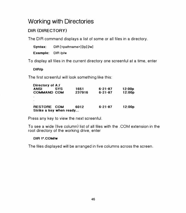
DIR (DIRECTORY)
The DIR command displays a list of some or all files in a directory.
Syntax: DIR [<pathname>] [/p] [/w]
Example: DIR /p/w
To display all files in the current directory one screenful at a time, enter
DIR/p
The first screenful will look something like this:
Directory of A:/ ANSI SYS COMMAND COM
1651 237916
RESTORE COM 6012 Strike a key when ready ...
6-21-876-21-87
6-21-87
Press any key to view the next screenful.
12:00p 12:00p
12:00p
To see a wide (five column) list of all files with the .COM extension in the root directory of the working drive, enter
DIR \*.COM/w
The files displayed will be arranged in five columns across the screen.
46
MKDIR (MAKE DIRECTORY)
The MKDIR command is used to make and name new directories and to create directories within directories.
Directory names can have up to eight characters and usually do not have extensions. (See Filenames in Chapter 2 for rules on naming directories.)
Syntax: MKDIR [<pathname>] <directory name>
Example: MKDIR \MAILBAG\ADDRESS
Follow these steps:
1. Create a directory named MAILBAG by entering
MKDIR MAILBAG
2. Create � directory named ADDRESS in MAILBAG by entering
MKDIR \MAILBAG\ADDRESS
Note: MD can be used in place of MKDIR. For example: MD MAILBAG.
CHOIR (CHANGE DIRECTORY)
The CHOIR command changes the current directory. It can also be used to display the current directory. Each drive in the system can have a different current directory.
Syntax: CHOIR <pathname>
Example: CHOIR \MAILBAG
The example given accesses the MAILBAG directory in the working drive and makes it the current directory.
47
To display the name of the current directory. enter the command followed by the working drive. For example:
CHOIR A:
Note: CD can be used in place of CHOIR. For example: CD \MAILBAG.
RMDIR (REMOVE DIRECTORY)
The RMDIR command removes a directory from the disk. Removing a directory erases it completely.
Syntax: RMDIR <pathname>
Example: RMDIR \MAILBAG\ADDRESS
The example given will erase the ADDRESS directory from MAILBAG.
You must erase all files (with DEL or ERASE) from a directory before you can erase the directory. This protects you from accidentally erasing files you want to keep. To preserve files. copy them (with COPY) to another directory before erasing them. You cannot remove a directory while it is the current directory.
Note: RD can be used in place of RMDIR. For example: RD \MAILBAG.
TREE
The TREE command displays the pathnames of all directories on the specified disk. Use TREE to see how a disk is organized.
Syntax: TREE [/1)
Example: TREE/I
The switch parameter /f (file) asks MS-DOS to display a list of all files on the working disk.
Change to the root directory (enter CD\) and enter the example given to display all directories on the disk and the files they contain.
48
PATH
The PA TH command tells MS-DOS where to look for command files or executable (program) files (files with the .COM or .EXE extensions) that are not in your current directory.
Syntax: PATH [<drive:>] [<pathname>]; [<drive:>] [<pathname>];[. .. ]
Example: PATH A:\;A:\COMMANDS
Entering the example given tells MS-DOS to look for command and program files in the root directory and COMMANDS directory of the disk in drive A. Notice that search parameters must be separated from each other by a semicolon (;).
To search the root directory of the current disk. enter
PATH\
To search\the root directory of a specific disk. add the drive parameter to the PA TH command. For example. if you're currently in drive A. entering
PATH B:\
searches the root directory of the disk in drive B.
You can add the PATH command to your AUTOEXEC.BAT file. For example. if you have a directory named WORDPROC that contains word-processing applications. adding PA TH \WORDPROC to your AUTOEXEC.BAT file lets you enter commands in WORDPROC from any directory.
To delete any parameters previously set with PA TH. enter
PATH;
49
Checking Disks, Directories, and Files
CHKDSK (CHECK DISK)
The CHKDSK command reports the total amount of system memory, how disk space is currently allocated, and which files. if any. are damaged or fragmented.
Syntax: CHKDSK [<drive:>] [<pathname>] [/I] [/v]
Example: CHKDSK B:/1/v
The switch parameter /f (fix) tells MS-DOS to correct any errors detected by CHKDSK. The switch parameter /v (view) tells MS-DOS to display the filenames of the files it checks.
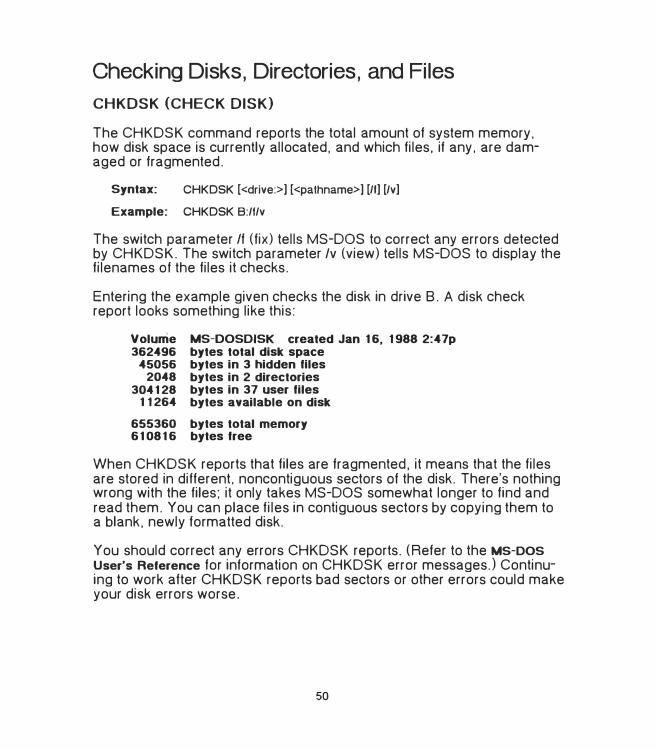
Entering the example given checks the disk in drive 8. A disk check report looks something like this:
Volume MS-OOSDISK created Jan 16, 1988 2:47p 362496 bytes total disk space
45056 bytes in 3 hidden files 2048 bytes in 2 directories
304128 bytes in 37 user files 11264 bytes available on disk
655360 bytes total memory 610816 bytes free
When CHKDSK reports that files are fragmented, it means that the files are stored in different. noncontiguous sectors of the disk. There's nothing wrong with the files: it only takes MS-DOS somewhat longer to find and read them. You can place files in contiguous sectors by copying them to a blank, newly formatted disk.
You should correct any errors CHKDSK reports. (Refer to the MS-DOS User's Reference for information on CHKDSK error messages.) Continuing to work after CHKDSK reports bad sectors or other errors could make your disk errors worse.
50
It's a good idea to add CHKDSK/f to your AUTOEXEC.BAT file in order to avoid working on damaged disks. CHKDSK will give you a system status report when you start up your system. If errors are reported. copy your usable disk contents to a new disk and reformat the damaged disk.
Printing Files
The PRINT command sends files to a printer. To use this command, make sure you have a printer connected to your system and ready to print.
Syntax: PRINT <pathname> [/I]
Example: PRINT \LETTER. TXT
Entering the example given prints the file LETTER. TXT in the root directory. You can specify up to ten files to print with one PRINT command by using wildcards in the pathname.
PRINT stores the file or files to be printed in a print queue buffer so you can continue working while printing is underway.
Once printing begins. you can stop it at any time by re-entering the command and adding the switch parameter It (terminate). Doing this also empties the print queue buffer. For example. entering
PRINT LETTER.TXT/1
stops printing the file LETTER.TXT. To resume printing, re-enter the PRINT command and your parameters. Printing begins from the top of the file.
The first time you use the PRINT command after starting up your system. MS-DOS asks you for the name of the list device (printer). If you have a parallel printer. press [Enter] to accept PAN as the list device. If you have a serial printer. enter COM as the list device.
51
MODE
The MODE command is used to tell MS-DOS whether you have a parallel or serial printer. It can also be used to set the parameters for a serial communications device (modem).
Syntax: MODE <device identifier> <device port number:>
Example: MODE LPT1: MODE COMl:9600,n,8, 1
Parallel printers are identified as LPT; serial devices are identified as COM. MODE must be correctly set in order for your computer to be able to use your printer.
If you are not using a standard parallel printer. add the MODE command and the correct parameter to your AUTOEXEC.BA T file.
Note: For information on using MODE for a modem and other parameters, refer to the MS-DOS User's Reference.
Monitor Display Mode Commands
Your Atari PC2 includes a graphics display subsystem that emulates the modes of a variety of other graphics display cards. These modes correspond to monochrome (MDA), color (CGA), or enhanced color monitors and different screen resolutions. Screen resolution is measured in pixels, or screen dots. The more pixels there are in your screen resolution. the crisper the images are in your screen display.
Selecting the correct display mode command lets you run applications that were developed for a particular mode. If you are unsure which mode is appropriate for your application. check the manual supplied with the software. The monitor display mode commands are supplied on MS-DOS Disks 1 and 2.
52
The modes you can use are determined by your monitor type and the software you will be using. For example, if you have an EGA monitor and software developed for EGA. you will want to use EGA mode for best performance. However. to use some older software packages on your EGA monitor. you may have to select CGA or MDA mode.
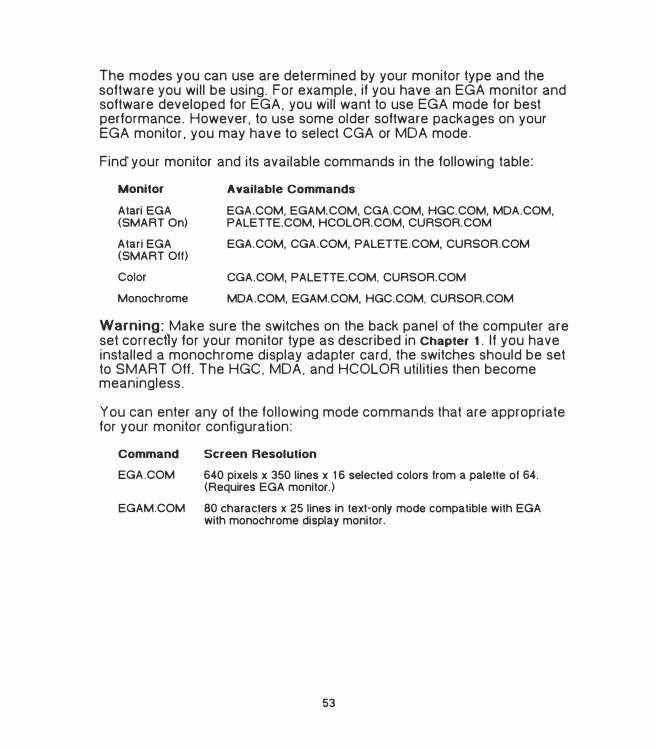
Find your monitor and its available commands in the following table:
Monitor
Atari EGA (SMART On)
Atari EGA (SMART Off)
Color
Monochrome
Available Commands
EGA.COM, EGAM.COM, CGA.COM, HGC.COM, MDA.COM, PALETTE.COM, HCOLOR.COM, CURSOR.COM
EGA.COM, CGA.COM, PALETTE.COM, CURSOR.COM
CGA.COM, PALETTE.COM, CURSOR.COM
MDA.COM, EGAM.COM, HGC.COM, CURSOR.COM
Warning:_ Make sure the switches on the back panel of the computer are set correctly for your monitor type as described in Chapter 1. If you have installed a monochrome display adapter card. the switches should be set to SMART Off. The HGC, MDA. and HCOLOR utilities then become meaningless.
You can enter any of the following mode commands that are appropriate for your monitor configuration:
Command Screen Resolution
EGA.COM 640 pixels x 350 lines x 16 selected colors from a palette of 64. (Requires EGA monitor.)
EGAM.COM 80 characters x 25 lines in text-only mode compatible with EGA with monochrome display monitor.
53
Command Screen Resolution
CGA.COM
MD A.COM
HGC.COM
640 pixels x 200 lines in monochrome or 320 pixels x 200 lines x 4 colors automatically selected by your applications program . (Requires EGA or CGA display .)
80 characters x 25 lines of monochrome text. (Requires EGA monitor with SMART On or MDA monitor.)
720 pixels x 348 lines in monochrome graphics mode; 80 characters (9 x 14 pixels each) x 25 lines in monochrome text mode. (Requires EGA monitor with SMART On or MDA monitor.)
You can change to EGA. CGA. or MDA mode by entering the mode command name by itself. For example, to change to CGA mode, enter
CGA
To use HGC mode, enter
HGC FUI..L
This command provides two complete HGC graphics pages. (The command variation, HGC HALF. provides only one graphics page, leaving more video memory space available for expansion boards.)
The Atari PC2 EGA subsystem has a mode save feature that lets it remember the current configuration, even after you perform a warmstart by pressing [Ctrl) [All] [Del]. This feature is very helpful when running selfbooting programs that are written for a mode other than the one the monitor select switches are set for.
Note: While the mode save information survives a warmstart. it does not survive switching the Atari PC2 off and on. When the computer is switched on with the on/off switch, it reads the monitor select switches to determine the initial display mode.
When your system is in EGA mode. you can use PALETTE.COM to specify which 16 of the 64 colors you want to use. For a menu of colors you can select. enter
PALETTE.COM
54
Use the [Up Arrow) and [Down Arrow) keys to move to the address of the color you want. Use the number keys to assign a number ( 1 to 16) to the color.
When you finish selecting colors. press [Esc). then respond to the enable palette save prompt. Press [YJ to save the palette and keep it in effect even when using software with another palette or doing a warmstart with [Ctrl) [All) [Del). Press [NJ if you want the software you use to keep its own palette and if you want the system default palette restored when you restart the system.
If you already know the addresses of the colors you want. you can enter them at the system prompt. For example. to select the first 16 colors and save the palette. enter
PALETTE c1 c2 c3 c4 c5 c6 c7 c8 c9 c10 c11 c12 c13 c14 c15 c16 /s
Omit Is if you don't want to preserve the palette across warmstarts.
When in HGC mode on an EGA monitor. you can use HCOLOR.COM to select a shade for the screen dot color. Enter
HCOLOR
Use [Pg Up) and [Pg On) to view the selections. Enter the number of the shade you want. Press [EscJ to save the change and exit. or [Q] to quit without saving the change.
A Few Other Useful Commands
CURSOR
The CURSOR command lets you set a blinking or nonblinking cursor at the system prompt.
Syntax: CURSOR <parameter>
Example: CURSOR NOBLINK
55
When you turn on your system. the cursor will appear as a blinking bar. If you'd like a nonblinking cursor. enter the example given.
Jo restore the blink. enter
CURSOR BLINK
PROMPT
The PROMPT command may be used to add the date. time. current directory. and other information to the system prompt.
Syntax: PROMPT [$DJ [$T] [$NJ [$P] [$_]
Example: PROMPT $D$_$T$_$N$P
In the PROMPT syntax. D stands for date. T for time. N for the working drive. P for the current directory, and_ for a line break. Each parameter i.s preceded.by the dollar sign ($).
Entering the example given creates a three-line prompt that displays the date. time. working drive. and current directory.
You can add the PROMPT command and its parameters to your AUTOEXEC.BAT file so it will automatically be in effect when you start up your system.
CLS (CLEAR SCREEN)
The CLS command clears the screen. then displays the system prompt.
Syntax: CLS
56
Common MS-DOS Error Messages
Sometimes MS-DOS displays an error message when you start up your system or enter a command. There's usually no reason to be alarmed. In most cases. you'll simply need to load the proper disk or re-enter the
· command.
The following is an alphabetical list of common error messages with anexplanation of what they mean and a description of the action you shouldtake when you see them. (For a complete list of error messages. see the.MS-DOS User's Reference.)
<TYPE> <ACTION> DRIVE <X> ABORT, IGNORE, RETRY
MS-DOS is unable to read or write to the specified drive because of some problem. The problem (type), whether it occurred while the drive was trying. to read or write (action). and the drive letter (x) are specified in the first line of the message.
The most common reasons for this message are that you are specifying a drive that isn't loaded with a disk or a drive that doesn't exist. Sometimes the problem type suggests what action to take. (For example. "Write-protect error" means you should remove the write-protection from the disk.) Remedy the problem and then respond by entering [R]. If you like. you can enter [AJ to stop the command and return to the system prompt.
BAD COMMAND OR FILENAME
You entered a command or filename that MS-DOS cannot recognize. If you're entering an external command (a command that is not built into the MS-DOS COMMAND. COM command interpreter) or feel certain the file exists, run the DIR command to make sure it's on the working disk (or in your execution PATH). Also, make sure the command or filename is
· spelled correctly before you enter it.
57
BAD OR MISSING COMMAND INTERPRETER
MS-DOS could not find the COMMAND.COM file it needs in order to start up. Either COMMAND.COM is missing or damaged or a startup disk is not loaded. Make sure a valid startup disk is loaded in drive A before you s�itch on your system.
BAD PARTITION TABLE
There is no MS-DOS partition on the hard disk. Create an MS-DOS partition by running option 1 on the FDISK menu as described in Appendix D and in the MS-DOS User's Reference.
ERROR READING/WRITING PARTITION TABLE
The FORMAT command could not read or write the partition table created when you ran FDISK. Run option 1 of FDISK again.
FILE NOT FOUND
See the explanation for "Bad command or filename."
INSERT DISK CONTAINING COMMAND.COM IN DRIVE A: AND STRIKE ANY KEY WHEN READY
This message may appear when you exit a program. It tells you that MS-DOS couldn't find COMMAND.COM. Reload COMMAND.COM by following the instructions in the message.
INTERNAL ST ACK ERROR
Enter the following line in the CONFIG.SYS file:
STACKS= 16, 128
58
INV AUD DRIVE SPECIFICATION
The drive you specified is not recognized by MS-DOS. Make sure all drives on your system are correctly installed and the cables secure. then re-enter the drive specification.
INVALID NUMBER OF PARAMETERS
You specified an incorrect number of parameters. Check the command syntax and re-enter the command.
INVALID PARAMETER
You entered an incorrect parameter with the command. Check the command syntax and re-enter the command.
INVALID PATH OR FILENAME
You specified a pathname or filename that does not exist on the current disk. Make sure the pathname or filename exists and is spelled correctly.
NO FIXED DISK INSTALLED
Your hard disk drive cables are improperly attached or the disk needs to be low-level formatted. Check your cable connections. If this message appears again. low-level format the disk as described Appendix D or in your hard disk manual (or contact your hard disk dealer tor·assistance).
NON-SYSTEM DISK OR DISK ERROR
REPLACE AND STRIKE ANY KEY WHEN READY
Either the startup drive does not contain a disk. or the startup disk does not contain the system files. Make sure the proper disk is loaded and press any key to continue.
59
SYNTAX ERROR
You incorrectly entered a command. Check the command syntax and re-enter the command.
TRACK n BAD--DISK UNUSABLE
The disk media at track n (where n is the number of the track) is defective and the disk cannot be formatted. Contact your hard disk dealer.
60
APPENDIX A
SYSTEM MAINTENANCE
In Case of Problems
If you run into problems operating your Atari PC3, don't panic. Chances are the difficulty is something you can easily remedy.
CHECK THESE FIRST
If your Atari PC3 just won't work--for instance. the power light won't come on or the monitor screen has no display--check these areas:
Power Switches Check that the computer. monitor, and all peripherals with power switches are switched on. and the brightness and contrast controls on,your monitor are properly adjusted.
Cable Connections Test all cables to make sure they're correctly and securely connected. Check the integrity of electrical outlets by plugging in a working desk lamp or other appliance.
Keyboard and Mouse If either your keyboard or mouse doesn't respond, it may be that it is not operational with the application you're using. With GEM Desktop, the keyboard generally doesn't respond except when you are naming items in a dialog box or using the mouse control keys. When you're working at the MS-DOS command line or in a program operated from the .keyboard. the mouse isn't operational.
Extra RAM After installing extra memory chips, check the amount of RAM displayed during system initialization. If the total amount of RAM (the standard 512 kilobytes plus the amount you installed) isn't shown. switch off and disconnect your system and carefully reseat the RAM chips. (For instructions, see Appendix e.)
61
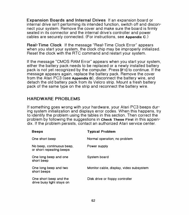
Expansion Boards and Internal Drives If an expansion board or internal drive isn't performing its intended function. switch off and disconnect your system. Remove the cover and make sure the board is firmly seated in its connector and the internal drive's controller and power cables are securely connected. (For instructions. see Appendix c.)
Real-Time Clock If the message "Real-Time Clock Error" appears when you start your system. the clock chip may be improperly initialized. Reset the clock with the ATC command and restart your system.
If the message "CMOS RAM Error" appears when you start your system. either the battery pack needs to be replaced or a newly installed battery pack is not yet recognized by the computer. Press [Fl) to continue. If the message appears again. replace the battery pack. Remove the cover from the Atari PC3 (see Appendix e), disconnect the battery wire. and detach the old battery pack from its Velcro strip. Mount a fresh battery pack of the same type on the strip and reconnect the battery wire.
HARDWARE PROBLEMS
If something goes wrong with your hardware. your Atari PC3 beeps during system initialization and displays error codes. When this happens. try to identify the problem using the tables in this section. Then correct the problem by fallowing the suggestions in Check These First in this appendix. If the problem persists. contact an authorized Atari service center.
Beeps
One short beep
No beep, continuous beep, or short repeating beeps
One long beep and one short beep
One long beep and two short beeps
One short beep and the drive busy light stays on
Typical Problem
Normal operation; no problem
Power supply
System board
Monitor cable, display, video subsystem
Disk drive or floppy controller
62
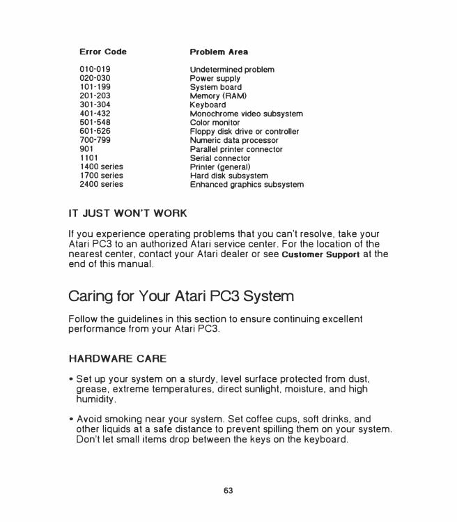
Error Code
010-019020-030101-199201-203301-304401-432501-548601-626700-79990111011400 series1700 series2400 series
IT JUST WON'T WORK
Problem Area
Undetermined problem Power supply System board Memory (RAM) Keyboard Monochrome video subsystem Color monitor Floppy disk drive or controller Numeric data processor Parallel printer connector Serial connector Printer (general) Hard disk subsystem Enhanced graphics subsystem
If you experience operating problems that you can't resolve, take your Atari PC3 to an authorized Atari service center. For the location of the nearest center, contact your Atari dealer or see customer Support at the end of this manual.
Caring for Your Atari PC3 System
Follow the guidelines in this section to ensure continuing excellent performance from your Atari PC3.
HARDWARE CARE
•Set up your system on a sturdy, level surface protected from dust.grease. extreme temperatures. direct sunlight. moisture, and highhumidity.
• Avoid smoking near your system. Set coffee cups, soft drinks. andother liquids at a safe distance to prevent spilling them on your system.Don't let small items drop between the keys on the keyboard.
63
• Always switch off your computer and peripherals before connecting ordisconnecting components.
• When you switch off the computer. wait at least ten seconds beforeswitching it on again.
• Switch off your computer before cleaning it. Clean only the outside ofthe components, using a soft, slightly damp, lint-free cloth. Do not usecleansers. abrasives. or solvents.
• Touch the metal frame of your computer to ground yourself afterremoving the cover and before installing chips, expansion boards.or internal drives.
• To ship or store your system. repack it in the original packing materials.Replace protective inserts in floppy disk drives and use a head par.kingprogram (if available) to park the heads on the hard disk.
'
FLOPPY DISK CARE
• Switch on your computer before inserting disks into the disk drives.Remove the disks before switching off the computer.
• Insert and remove disks from the drive only when you're sure the drive'sbusy light is off.
• Store your disks upright in their protective envelopes away fromextreme heat. moisture, direct sunlight, and sources of magnetism(monitor. television. electric motor. telephone. and so on).
• Never touch a disk's magnetic media. Don't bend disks or use paperclips on them.
64
APPENDIX B
INST ALLING EXTRA RAM AND
THE NUMERIC DAT A PROCESSOR
Your Atari PC3 can accommodate extra RAM chips and a numeric data processor. The extra RAM increases the system's memory to 640 kilobytes and the numeric data processor speeds calculations. Many applications require extra RAM to run or are designed to take advantage of a numeric data processor. You can obtain these chips from your Atari dealer.
Installing these chips is done by removing the computer's cover and inserting microchips on the motherboard. While the installation is not difficult, you should take care to follow the instructions exactly.
The RAM s,ockets hold four 64 kilobyte x 4 dynamic RAM chips. The chips (labeled 41464-15 or 41464-12) should be rated at a speed of 150 ns or higher. You should install all four chips. You can also install any of the following Intel numeric data processors:
8087 (5 MHz) 8087�2 (8 MHz) 8087-1 (10 MHz)
Warning: If you install the 5 MHz numeric data processor. you will not be able to use the Atari PC3's turbo mode.
The following steps describe how to install the chips.
Warning: If you perform any operation or modification to the inside of your computer other than those described in this manual. Atari Corporation reserves the right to disclaim warranty for your Atari PC3 or any other adversely affected component. Also. your Atari PC3 warranty does not cover damage caused by hardware or software not manufactured by Atari Corporation.
1. Be sure your computer is switched off. unplugged. and disconnectedfrom all other peripherals.
65
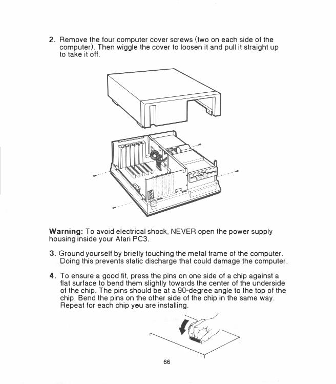
2. Remove the four computer cover screws (two on each side of thecomputer). Then wiggle the cover to loosen it and pull it straight upto take it off.
Warning: To avoid electrical shock, NEVER open the power supply housing inside your Atari PC3.
3. Ground yourself by briefly touching the metal frame of the computer.Doing this prevents static discharge that could damage the computer.
4. To ensure a good fit. press the pins on one side of a chip against aflat surface to bend them slightly towards the center of the undersideof the chip. The pins should be at a 90-degree angle to the top of thechip. Bend the pins on the other side of the chip in the same way.Repeat for each chip yi,u are installing.
66
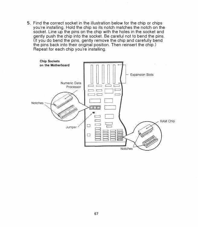
5. Find the correct socket in the illustration below for the chip or chipsyou're installing. Hold the chip so its notch matches the notch on thesocket. Line up the pins on the chip with the holes in the socket andgently push the chip into the socket. Be careful not to bend the pins.(If you do bend the pins. gently remove the chip and carefully bendthe pins back into their original position. Then reinsert the chip.)Repeat for each chip you're installing.
Chip Sockets
on the Motherboard
Notches
Numeric Data Processor
c:J D
�c:J
D
Iii'
c::::J D c::::J c::::J
67
Expansion Slots
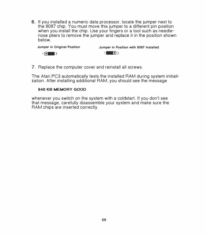
6. If you installed a numeric data processor. locate the jumper next tothe 8087 chip. You must move this jumper to a different pin positionwhen you install the chip. Use your fingers or a tool such as needlenose pliers to remove the jumper and replace it in the position shownbelow.
Jumper in Original Position
1�3
Jumper in Position with 8087 Installed
1 lllllll!l 3
7. Replace the computer cover and reinstall all screws.
The Atari PC3 automatically tests the installed RAM during system initialization. After installing additional RAM. you should see the message
640 KB MEMORY GOOD
whenever you switch on the system with a coldstart. If you don't see that message, carefully disassemble your system and make sure the RAM chips are inserted correctly.
68
APPENDIX C
INSTALLING EXPANSION BOARDS
AND INTERNAL DRIVES
Adding optional expansion boards and internal drives to your Atari PC3 increases the functionality of your system and lets you customize it to suit your needs. You can install optional devices yourself by following the instructions in this appendix.
Warning: If you perform any operation or modification to the inside of your computer other than those described in this manual. Atari Corporation reserves the right to disclaim warranty for your Atari PC3 or any other adversely affected component. Your Atari PC3 warranty does not cover damage caused by hardware or software not manufactured by Atari Corporation .
Your Atari PC3 has five slots for full-size or half-size expansion boards. You can add XT-compatible hard disk controller. network. modem. or other boards in these slots. The system also has two drive bays for floppy disk. hard disk. tape, removable data cartridge, or other PC XTcompatible internal drives.
The Atari PC3 is equipped with a floppy drive controller that can be connected to two drives (generally floppy disk drives. but some tape drives also use the floppy disk controller). Hard disks and other types of drives require separate controller boards.
Follow the instructions in this appendix to secure a board or internal drive in the Atari PC3 and find the connectors and/or cables you'll need to complete the installation. Use the instructions supplied with the device for specific information on preparing the device and connecting cables. (The instructions supplied with the device may assume a PC system built differently from the Atari PC3.)
Note: When setting up internal options in your system. install the RAM and 8087 chips BEFORE you install expansion boards. (See Appendix B
for instructions.) Full-size expansion boards cover the chip sockets and must be removed in order to access them.
69
Selecting and Configuring an Expansion Board
The Atari PC3 includes on its motherboard many features that require adapter or expansion boards on other PCs. These features (video subsystem. floppy disk controller. and serial, parallel. and mouse interfaces) use part of the 8088 processor's 1/0 address space and available interrupts. Optional expansion boards for the Atari PC3 must be configured so they don't conflict with these built-in controllers and interfaces.
Configuring a board involves selecting an 1/0 address and interrupt channel with the board's jumpers and/or switches. (See the documentation supplied by the manufacturer for information on locating and changing jumpers and switches.) The 1/0 address is the storage location the processor uses for the exchange of data between itself and the board. The interrupt is the channel the board uses when it needs to interrupt an operation in order to communicate with the processor.
Two peripherals cannot have the same 1/0 address. but interrupt channels can sometimes be shared, depending on your software. When selecting an interrupt, keep in mind that when all the Atari PC3's controllers and interfaces are employed, all available interrupts will be used.
To avoid the possibility of interrupt conflicts. select an unused interrupt channel. For example, if you are not using the mouse and do not load its driver (either MOUSE.COM or MOUSE.SYS). select interrupt 3 (IR03). Interrupt 2 (IR02) is a good choice if you don't use EGA mode. If the interrupt channel you select conflicts with another peripheral. the board will not be able to communicate successfully with the processor.
70
The table below lists the Atari PC3's built-in controllers and interfaces and their 1/0 addresses and interrupts. When selecting a board for your computer. make sure it can be configured for an 1/0 address and interrupt you are not using.
Interlace 1/0 Address Interrupt
Video subsystem 3CO - 3CF (in EGA mode) IR02 380 - 3BF (in MDA mode) 300 - 3DF (in CGA or EGA mode)
Mouse interface 23C - 23F IR03
Serial interface ( COM 1) 3F8 - 3FF IR04
Hard disk controller 320 - 32F IR05
Floppy disk controller 3FO - 3F7 IR06
Parallel printer interface 378 - 37F IR07
Note: For information on configuring your expansion boards. see the documentation supplied with the expansion board or contact the board's manufacturer.
Installing an Expansion Board
The slot you choose for an expansion board depends on the particular requirements of the board. If your board connects to a cable. choose a slot that allows the cable to be connected easily and properly. If the manufacturer recommends that you position the board for maximum airflow. choose a slot next to a vacant slot (if one is available).
Follow these steps to install a board:
1. Switch off your computer system and unplug it from the electricaloutlet.
71
2. Remove the computer's cover as described in Appendix B. You will
see the interior of the computer.
Warning: To avoid electrical shock. NEVER open the power supply housing inside your Atari PC3.
Expansion Slots
3. Ground yourself by briefly touching the metal frame of the computer.
Doing this prevents static discharge that could damage the computer.
4. Remove the slot cover screw and slide out the slot cover. Save the
screw for step 6.
Y -s1ot Cover Screw
� �Slot Co,e1
72
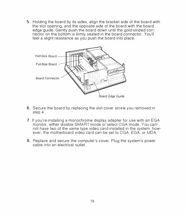
5_ Holding the board by its sides. align the bracket side of the board with the slot opening, and the opposite side of the board with the board edge guide. Gently push the board down until the gold-striped connector on the bottom is firmly seated in the board connector. You'll feel a slight resistance as you push the board into place.
Full-Size Board
Board Connector
Board Edge Guide
6_ Secure the board by replacing the slot cover screw you removed in step 4.
7 _ If you're installing a monochrome display adapter for use with an EGA monitor. either disable SMART mode or select CGA mode. You cannot have two of the same type video card installed in the system; however. the motherboard video card can be set to CGA, EGA. or MDA.
8_ Replace and secure the computer's cover. Plug the system's power cable into an electrical outlet.
73
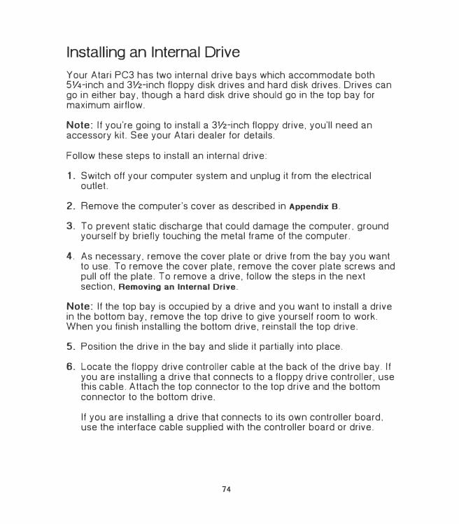
Installing an Internal Drive
Your Atari PC3 has two internal drive bays which accommodate both 5V4-inch and 3V2-inch floppy disk drives and hard disk drives. Drives can go in either bay. though a hard disk drive should go in the top bay for maximum airflow.
Note: If you're going to install a 3V2-inch floppy drive. you'll need an accessory kit. See your Atari dealer for details.
Follow these steps to install an internal drive:
1. Switch off your computer system and unplug it from the electricaloutlet.
2. Remove the computer's cover as described in Appendix B.
3. To prevent static discharge that could damage the computer. groundyourself by briefly touching the metal frame of the computer.
4. As necessary, remove the cover plate or drive from the bay you wantto use. To remove the cover plate. remove the cover plate screws andpull off the plate. To remove a drive. follow the steps in the nextsection. Removing an Internal Drive.
Note: If the top bay is occupied by a drive and you want to install a drive in the bottom bay. remove the top drive to give yourself room to work. When you finish installing the bottom drive. reinstall the top drive.
5. Position the drive in the bay and slide it partially into place.
6. Locate the floppy drive controller cable at the back of the drive bay. Ifyou are installing a drive that connects to a floppy drive controller: usethis cable. Attach the top connector to the top drive and the bottomconnector to the bottom drive.
If you are installing a drive that connects to its own controller board.use the interface cable supplied with the controller board or drive.
74
7. Locate the power cable stemming from the power supply housing andattach either of its connectors to your drive.
Installing an Internal Drive
Power Connectors
Power / Cable /-
Floppy Drive Controller Cable
Top Connector
5 '.4 -Inch Internal Floppy Drive
8. Slide the drive completely into the drive bay and secure it to the baywith eight screws (four on each side, supplied by the manufacturer).
Note: A 3V2-inch hard disk can also be mounted on the internal frame of your Atari PC3. For more information. contact your Atari dealer.
75
REMOVING AN INTERNAL DRIVE
Follow these steps to remove an internal drive from the drive bay:
1. Switch off and unplug your computer system.
2. Remove the computer's cover as described in Appendix e. To preventstatic discharge that could damage the computer, ground yourself bybriefly touching the metal frame of the computer.
3. Remove the eight screws (four on each side of the drive) that securethe drive in the drive bay. Disconnect all cables at the back of thedrive.
4. Gently slide the drive out of the drive bay.
76
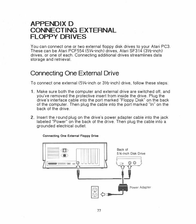
APPENDIX D
CONNECTING EXTERNAL
FLOPPY DRIVES
You can connect one or two external floppy disk drives to your Atari PC3. These can be Atari PCF554 (5V4-inch) drives, Atari SF314 (3V2-inch) drives. or one of each. Connecting additional drives streamlines data storage and retrieval.
Connecting One External Drive
To connect one external (5V4-inch or 3V2-inch) drive, follow these steps:
1. Make sure both the computer and external drive are switched off. andyou've removed the protective insert from inside the drive. Plug thedrive's,interface cable into the port marked "Floppy Disk" on the backof the computer. Then plug the cable into the port marked "In" on theback of the drive.
2. Insert the r-0und plug on the drive's power adapter cable into the jacklabeled "Power" on the back of the drive. Then plug the cable into agrounded electrical outlet.
Connecting One External Floppy Drive
Back of
5�-lnch Disk Drive
77
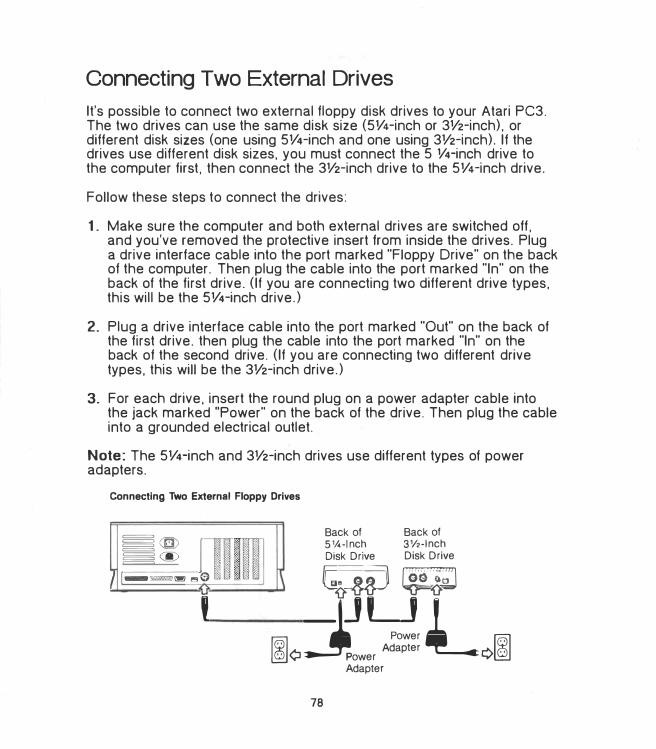
Connecting Two External Drives
It's possible to connect two external floppy disk drives to your Atari PC3. The two drives can use the same disk size (5V4-inch or 3V2-inch). or different disk sizes (one using 5V4-inch and one using 3V2-inch). If the drives use different disk sizes. you must connect the 5 V4-inch drive to the computer first. then connect the 3V2-inch drive to the 5V4-inch drive.
Follow these steps to connect the drives:
1. Make sure the computer and both external drives are switched off,and you've removed the protective insert from inside the drives. Pluga drive interface cable into the port marked "Floppy Drive" on the backof the computer. Then plug the cable into the port marked "In" on theback of the first drive. (If you are connecting two different drive types.this will be the 5V4-inch drive.)
2. Plug a drive interface cable into the port marked "Out" on the back ofthe first drive. then plug the cable into the port marked "In" on theback of the second drive. (If you are connecting two different drivetypes. this will be the 3V2-inch drive.)
3. For each drive. insert the round plug on a power adapter cable intothe jack marked "Power" on the back of the drive. Then plug the cableinto a grounded electrical outlet.
Note: The 5V4-inch and 3V2-inch drives use different types of power adapters.
Connecting Two External Floppy Drives
�@
I�@ / l111111111111111SES:JI!!!) ... 0
'
Back of 5 V.-lnch Disk Drive
Back of 3V2-lnch Disk Drive
G�-�iJ �iiJ
:iJLJl_ Power
1¢ Power Adapter ¢1
Adapter
78
APPENDIX E
PREPARING AND WORKING
WITH A HARD DISK
If your Atari PC3 arrives equipped with a hard disk. you must prepare the disk before you can use it to store data. Instructions for preparing the disk are given in Preparing a Hard Disk in this appendix. If you have installed another manufacturer's hard disk in your Atari PC3. follow the manufacturer's instructions to prepare your hard disk.
After preparing the hard disk. read Working with a Hard Disk in this appendix for information on organizing and protecting your hard disk data.
Preparing a Hard Disk
In order to' store information on a hard disk. you must prepare it with the FDISK and FORMAT commands.
FDISK
The FDISK command creates a partition that identifies all or part of the hard disk to the operating system. A partition is a storage area on disk normally used to hold files created with a specific operating system. You can have from one to four partitions on your hard disk.
If your system has an Adaptec hard disk controller. you can create separate logical drives. Each drive can have a total of four partitions. If you want to create logical drives. do so before running FDISK. (See Low
Level Formatting in this appendix for more information.)
To use all of your hard disk storage for an MS-DOS partition. follow the steps below to run FDISK. To create a smaller MS-DOS partition so you'll have room for up to three other operating systems. see FDISK in your MS-DOS User's Reference.
79
1. With the MS-DOS disk containing FDISK in drive A. start the programby entering
FDISK
Warning: If the hard disk needs to be low-level formatted, the message "No fixed disk installed" will appear when you attempt to run FDISK. See Low-Level Formatting in this appendix for further instructions. When you finish low-level formatting the disk, run FDISK again.
2. When the FDISK menu appears. press [Enter] to select the defaultchoice of 1. Create DOS Partition.
3. If the disk has already been partitioned. a message indicating this factappears. You can begin formatting the disk by running the FORMATcommand described in the following section, FORMAT.
If the disk has not yet been partitioned. a message appears asking if you want to use the entire disk for the DOS partition. Press [Enter] to respond "Yes."
4. When prompted to insert a DOS disk into drive A. make sure MS-DOSDisk 1 is in drive A. then press any key. MS-DOS reboots and thesystem prompt appears.
FORMAT
Like a floppy disk, a hard disk must be formatted before you can store information on it. Use the FORMAT command to format each MS-DOS partition on your hard disk.
Warning: Running the FORMAT command permanently erases all information on the partition you're formatting. If there are any files on the partition that you want to keep, copy them to another disk before proceeding.
Syntax: FORMAT <MS-DOS partition letter> [/s) [/v)
Example: FORMAT C:/s/v
80
Entering the example given formats MS-DOS partition C. The /s (system) switch copies the system files to the partition. making drive C your startup drive. (To use the /s switch. make sure MS-DOS Disk 1 is in drive A.)
Note: Only the startup MS-DOS partition requires the system files.
The /v (volume) switch asks you to enter a volume name for the partition. Type a name and press [Enter]. The volume name of 11 characters or less will now appear each time you display a directory of the partition.
When you restart the Atari PC3, the system will attempt to boot from a floppy disk. To allow the system to boot from the hard disk, remove the disk from drive A before restarting the system (either with a coldstart or warmstart). The system prompt appears as C > instead of A>.
Working with a Hard Disk
Working with a hard disk is essentially the same as working with a floppy disk except you'll enjoy speedier disk operations. greater storage capacity, and the convenience of having most of your files on one disk.
ORGANIZING YOUR HARD DISK
Larger disk storage capacity means that careful directory and file organization is more important than ever. When planning and using your tree structure of directories and files. keep the following hints in mind:
• Keep as few files as possible in the root directory. Normally. the onlyitems you need in the root directory are the first level of directories andthe COMMAND.COM. AUTOEXEC.BAT. and CONFIG.SYS files.
• Keep the programs and files you use most often in the first level ofdirectories.
• Stay within the first few levels of directories. It's easiest to find directories and files when your directory structure consists of no more thanthree levels (the root directory and two levels of directories).
81
• To check the name of the current directory, enter the CHOIR commandby itself. Or use the PROMPT command in your AUTOEXEC.BAT fileto include the current directory name in the system prompt.
• Free disk space for new files by deleting directories and files you nolonger need.
PARKING THE DISK HEADS
Always run a hard disk head-parking utility before moving or shipping your hard disk. A head-parking program protects data on the hard disk by parking the hard disk heads over a safe zone (one that contains no data).
It's a good idea to run the head-parking utility after every work session. just before you switch off your system. If your hard disk was supplied with your Atari PC3, use the HDSHIP program (supplied on the MS-DOS disks). To run HDSHIP. enter
HD SHIP
When you restart your system. the heads will automatically "unpark."
Note: If you have a hard disk supplied by another manufacturer. use the manufacturer's head parking program. If a program was not supplied with the disk. contact the manufacturer for more information.
BACKING UP THE HARD DISK
It's important to frequently back up data on the hard disk. To do that. regularly copy important files onto floppy disks and store them in a safe place. Otherwise. files that are accidentally deleted or damaged will be lost forever. As a general rule. it's good practice to back up all files on your hard disk every week or so and back up new or modified files each time you work on them.
82
In addition to the BACKUP, RESTORE. XCOPY, and COPY commands in MS-DOS, you can use any of the handy hard disk backup programs available through dealers and user groups. You can also use a tape backup system. Enter the command examples that follow or refer to the MS-DOS User's Reference for additional command variations.
Note: The command examples assume you are backing up or restoring files between hard disk drive C and floppy disk A. To back up or restore files between other physical or logical hard disk drives. substitute the appropriate drive letters.
The BACKUP and RESTORE Commands
The BACKUP command backs up all files on your hard disk or all files modified or added since the last time you used BACKUP. If files on your hard disk are accidentally deleted or damaged, you can recover them with the RESTORE command.
'
You'll need a number of formatted, double-sided floppy disks to complete the backup. The exact number depends on how full your hard disk is. If you have a 20-megabyte hard disk filled to capacity. you'll need about fifty 5V4-inch double-sided disks to complete the backup.
Enter this command to back up all directories and files on hard disk C by copying them to floppy drive A:
BACKUP C:\*.* A:/s
The BACKUP command displays the directory names and filenames as they are backed up. When a floppy disk is full. you'll be prompted to insert a new disk. Label and number each backup disk consecutively so you'll be able to restore the hard disk data properly if they are damaged or lost.
To back up only the files modified or added since the last time you used BACKUP on the disk, enter:
BACKUP C:*. * A:/m/s
83
Once you've backed up files with BACKUP. you can restore them to the hard disk if they're accidentally damaged or deleted. Use the RESTORE command to restore all files by entering
RESTORE A: C:\•. *Is
You will be prompted to insert the backup disks in the order you backed them up.
The XCOPY and COPY Commands
The XCOPY command backs up a directory and all the items (directories and files) it contains. For example. to back up the directory LETTERS and all its items from hard disk C to floppy drive A. enter
XCOPY C:\LETTERS A:/s
To restore directories and files backed with XCOPY. use the COPY command for each directory you want to copy from the floppy disk to the hard disk. For example. to copy the directory LETTERS and all its items. enter
COPY A:\LETTERS\*.* C:
Use the COPY command to copy a single file or group of files in the same directory to another disk. For example. to copy all files with the extension .TXT in the directory LETTERS. enter
COPY C:\LETTERS\*.TXT A:
To restore these files. enter
COPY A:*. TXT C:\LETTERS
84
Low-Level Formatting
Most hard disks are low-level formatted during production. The low-level format divides the disk into sectors and cylinders and determines what portions of the disk will be used to store data. If the disk hasn't been lowlevel formatted or the low-level format becomes partially erased during shipping, you must low-level format it before you can create and format an MS-DOS partition. Always low-level format the disk when you're certain it's properly connected to your system but you see the message "No fixed disk installed" when you run FDISK.
Follow the instructions in the next sections to low-level format your hard disk. After low-level formatting, run the FDISK and FORMAT commands as described in Preparing a Hard Disk in this appendix.
STARTING THE LOW-LEVEL FORMATTING PROGRAM
To run the l'Ow-level formatting program. follow these steps:
1. Insert the MS-DOS disk containing the DEBUG command into yourworking drive and enter
DEBUG
The system prompt reappears as a hyphen (-).
2. To display on screen what type of controller board you have in yoursystem. enter
D = C800:0
If your controller board is an Adaptec. follow the steps in the next section. The Adaptec Low-Level Formatting Program. If your controller board is an Epson, follow the steps in The Epson Low-Level Formatting Program. If your controller board is an OMTI. follow the instructions in The OMTI Low-Level
Formatting Program.
85
THE ADAPTEC LOW-LEVEL FORMATTING PROGRAM
Use the following specifications if you are prompted for them while running the low-level formatting program:
Prompt
Interleave value Detect byte offset encoding . Buffered seek pulse rate Control byte Heads Cylinders
Specification
3
RLL
13 microseconds 10 4
615
Warning: If you are unable to low-level format your hard disk successfully with the specifications given. your Atari PC3 may have a hard disk that uses different specifications. Contact your Atari dealer for the correct specifications to use with your hard disk.
If you are iristalling a hard disk from another manufacturer. use the specifications supplied with the drive or contact the manufacturer for the correct specifications.
To run the Adaptec low-level formatting program. follow these steps:
1. Start the program from the DEBUG prompt by entering
G = C800:CCC
2. Respond to the sector interleave prompt by entering the interleavevalue recommended by the manufacturer. For example. to set theinterleave to 3, enter
3
An interleave value of 3 means that your hard disk requires threerevolutions to read an entire track. This is usually the most efficientvalue for your system.
86
3. Respond to the Drive ID prompt by specifying which hard disk youwant to low-level format. If you have one hard disk in your system. itis drive 0. If you have two hard disks. one is drive O (the startup drive)and the other is drive 1.
To low-level format drive 0. enter
0
To low-level format drive 1. enter
1
4. Respond to the default parameters prompt. To accept the defaultparameters. enter
y
and go ,on to step 5.
To divide the disk into logical drives (accessed by separate driveletters) enter
N
As prompted, enter the number of logical drives (from 1 to 8) and abuffered seek step pulse rate code. Find the rate recommended bythe hard disk drive manufacturer in the following table and enter thecorresponding code.
Seek Step Pulse Rate Code
3.0 milliseconds O
30 microseconds 2
13 microseconds 3
200 microseconds 4
70 microseconds 5
If you can't find the manufacturer's recommended rate. use code 3.
Respond to the heads and cylinders prompts with the correct values for your drive.
87
Note: Your system treats each logical drive as a separate drive that can be accessed with a drive letter (C. D. E. and so on). Using the FDISK command described in your MS-DOS User's Reference, you can divide each of these logical drives into partitions for different operating systems. Each logical drive can have only one MS-DOS partition..
5. Respond to the defective track prompts by specifying a defect byteoffset encoding type (RLL) and a defect list format (Cyl/Head/Byteor Head/Cyl/Byte).
Enter
R
to select RLL.
If you don't have a defective track list, enter
c
to select Cyl/Head/Byte for the defect list format and press [Enter) to continue.
If you do have a defective track list. enter it in the selected format. Separate cylinder, head, and byte values with slashes(/) and press [Enter) after each set. For example. 32/4/4055 in Cyl/Head/Byte format means cylinder 32, head 4. byte 4055. A list in this format might look like this:
32/4/4055 [Enter) 255/3/2266 [Enter) 543/2/3418 [Enter I
As prompted. enter [YI if the values are correct or [NJ if they are incorrect. If you enter [NI. you return to the beginning of the low-level formatting program.
88
The low-level formatting begins. When it is finished. all tracks are verified (this takes about 40 seconds per megabyte). Status messages inform you of the progress of the formatting and verification. (The cylinder numbers displayed are physical. not logical.)
Note: For a list of error codes that may appear during formatting and track verification. see the next section, Adaptec Low-Level Formatting Errors.
When formatting and verification are complete, you'll be prompted to press (VJ to run the program again or [NJ to return to the MS-DOS system prompt.
Adaptec Low-Level Formatting Errors
The following is a list of error codes that may appear during low-level formatting with the Adaptec low-level formatting program. Some errors are normal and mean that defective tracks are being flagged as intended. Any error that terminates low-level formatting before it is finished should be reported to your authorized Atari service center.
Code Error
01 Bad command passed to disk 1/0 02 Address mark not found 04 Requested sector not found 05 Reset failed 07 Drive parameter activity failed 09 Attempt to DMA across 64 kilobyte boundary OB Bad track flag detected 1 0 Bad ECC on disk read 11 ECC corrected data error 20 Controller failure 40 Seek operation failed 80 Attached/failed to respond BB Undefined error occurred FF Send operation failed
89
THE EPSON LOW-LEVEL FORMATTING PROGRAM
To run the Epson low-level formatting program. follow these steps:
1. Enter the following at.the DEBUG prompt:
A100
2. Enter the following parameters exactly as shown to low-level formatdrive 0.
MOV DX, 80 [Enter]MOV ex, 1 [Enter]MOV AX, 0702 [Enter]INT 13 [Enter]INT 3 [Enter][Enter]G = 100 [Enter]
To low-level format drive 1, enter the same parameters, but changethe first line to
MOV DX, 81 [Enter]
Low-level formatting begins. When it is finished. you'll see three lines of values (beginning with AX = 00 if no defects were found).
To quit the DEBUG program and return to the MS-DOS system prompt. enter
Q
THE OMTI LOW-LEVEL FORMATTING PROGRAM
To run the OMTI low-level formatting program. follow these steps:
1. Enter the following at the DEBUG prompt:
G = C800:6
90
2. Respond to the format prompt by ·entering
y
3. To low-level format drive 0, respond to the drive number prompt byentering
0
To low level format drive 1, enter
1
4. Respond to the defaults prompt by entering
N
Respond to the next prompts as follows:
Total cyls: Total heads: Write Precomp Cyl: Control Byte:
615 [Enter) 4 [Enter) [Enter) (No value required.) 1 [Enter)
5. The logical partitioning prompt lets you determine whether or not yourdrive will be divided into logical partitions. To divide the disk into logicalpartitions. enter
N
at this prompt and enter the cylinder size of each logical drive (up toeight logical drives).
To use the entire disk as one partition. enter
y
91
6. The defects prompt lets you enter the values on your defective trackmap. (This map is usually on a sticker affixed to the drive.) If you don'thave a defective track map, enter
N
If you do have a defective track map, enter the cylinder and headvalues of each defect as prompted. When you are finished enteringdefect values. respond to the "More entries?" prompt by entering
N
7. Respond to the interleave prompt by entering
3
8. The final prompt gives you a chance to exit the program before lowlevel formatting begins by entering
N
Or you can go ahead with the formatting by entering
y
When low-level formatting is finished, press any key to reboot the system.
92
APPENDIX F
AT ARI PC3 SPECIFICATIONS
COMPUTER
Processor
Clock Rate
Memory:
RAM
ROM
Ambient Temperature:
Operating/idle Storage Transport
Relative Humidity (noncondensing):
Operating/idle Storage/ transport
Power Supply Consumption
Power
Operating System
8088
4.77 MHz standard PC mode. or 8.0 MHz turbo mode (switchable under keyboard or program control)
512 kilobytes standard ,. 640 kilobytes with extra RAM chips (four 64 kilobyte x 4 dynamic RAM; 41464-15, 41464-12, or equivalent)
32 kilobytes
41' to113' F -4' to140' F-40' to 140' F
20% to 80% Up to 95%
(5' to 45' C) (-20' to 60' C) (-40' to 60' C)
130 watts. internal
200 watts maximum
MS-DOS version 3.2
93
Interfaces
Expansion Slots
Numeric Data Processor Socket
Dimensions: Height Width Depth
XT-protocol keyboard jack Quadrature mouse port Video monitor connector RS 232C serial port Parallel printer port Floppy disk drive port Two internal disk drive connectors
Five vertical XT-type
Uses an 8087 ( 5 MHz). 8087-2 ( 8 MHz). or 8087- 1 ( 10 MHz) numeric data processor chip
6in. ( 15.2cm) 15 in. ( 38. 1 cm) 16.25 in . ( 41.3 cm)
VIDEO GRAPHICS ADAPTER
Monitor Types
Display Modes:
EGA
CGA
Monochrome display Color display
Enhanced display (EGA)
Monitor: EGA
Screen resolution and colors: 640 pixels x 35 0 lines x 16 selected colors from palette of 64
Typical character cell size: 8 x 14 pixels
Monitors: EGA. color
Screen resolution and colors: 640 x 200 lines in monochrome or 320 pixels x 200 lines x 4 colors (automatically selected by the application)
Typical character cell size: 8 x 8 pixels
94
MDA
HGC
Monitors: EGA. monochrome
Screen resolution: 80 characters x 25 lines of text
Typical character cell size: 9 x 14 pixels
Monitors: EGA. monochrome
Screen resolution and colors: 720 pixels x 348 lines in monochrome graphics mode or 80 characters x 25 lines in text mode
Typical character cell size: 9 x 14 pixels
5Y•-INCH FLOPPY DISK DRIVE
Tracks
Sector Size
Storage Capacity
Rotational Speed
Data Transfer Rate
Step Rate
Controller
KEYBOARD
Features
Dimensions:
Max. height Width Depth
Weight
40
512 bytes
360 kilobytes
300 rpm
250 kilobytes/second
Less than 6 microseconds
Support for two internal and two external devices
IBM PC AT layout: IBM PC XT protocol compatible; 84 keys including 56 typewriter keys, 10 function keys, and 18 keypad keys
1.5 in. (3.8 cm) 17.75 in. (45 cm) 7.75 in. (19.5 cm)
3.5 lb. ( 1.6 kg)
95
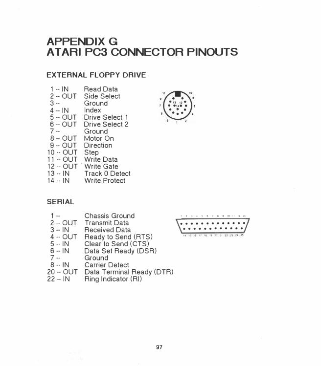
APPENDIX G
AT ARI PC3 CONNECTOR PINOUTS
EXTERNAL FLOPPY DRIVE
1 -- IN Read Data 2 -- OUT Side Select 3 -- Ground 4 -- IN Index 5 -- OUT Drive Select 1 6 -- OUT Drive Select 2 7 -- Ground 8 -- OUT Motor On 9 -- OUT Direction
10 -- OUT Step 11 -- OUT Write Data 12 -- OUT ' Write Gate 13-- IN Track O Detect 14 -- IN Write Protect
SERIAL
1 --2 -- OUT 3 -- IN
Chassis Ground Transmit Data Received Data
4 -- OUT 5 -- IN 6 -- IN 7 --
Ready to Send (RTS) Clear to Send (CTS) Data Set Ready (DSR) Ground
8 -- IN 20 -- OUT 22 -- IN
Carrier Detect Data Terminal Ready (DTR) Ring Indicator (RI)
97
I 1 ) • !) 6 1 8 9 IQ II 11 I)
• • • • • • • • • • • • •
• • • • • • • • • • • •
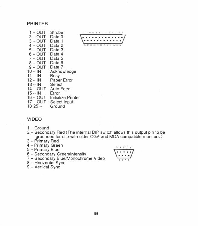
PRINTER
1 -- OUT Strobe 2 -- OUT Data O 3 -- OUT Data 1 4 -- OUT Data 2 5 -- OUT Data 3 6 -- OUT Data 4 7 -- OUT Data 5 8 -- OUT Data 6 9 -- OUT Data 7
10 -- IN Acknowledge 11 -- IN Busy 12 -- IN Paper Error 13 -- IN Select 14 -- OUT Auto Feed 15 -- IN Error 16 -- OUT Initialize Printer 17 -- OUT Select Input 18-25 -- Ground
VIDEO
1 -- Ground
I] I] 11 10 9 8 I f, !t • J ] I
• • • • • • • • • • • • •
• • • • • • • • • • • •
2 -- Secondary Red (The internal DIP switch allows this output pin to be grounded for use with older CGA and MDA compatible monitors.)
3 -- Primary Red 4 -- Primary Green 5 -- Primary Blue 6 -- Secondary Green/Intensity 7 -- Secondary Blue/Monochrome Video8 -- Horizontal Sync 9 -- Vertical Sync
98
• • • •
9 8 7 6
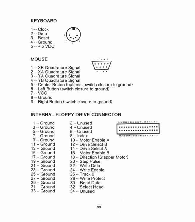
KEYBOARD
1 -- Clock 2 -- Data 3 -- Reset 4 -- Ground 5 -- + 5 voe
MOUSE
30· · •••
5 •
1 -- XB Quadrature Signal 2 -- XA Quadrature Signal • ' • •
3 -- YA Quadrature Signal 4 -- YB Quadrature Signal 5 -- Center Button (optional, switch closure to ground) 6 -- Left Button (switch closure to ground) 7 -- vcc
8 -- Grourid 9 -- Right Button (switch closure to ground)
INTERNAL FLOPPY DRIVE CONNECTOR
1 -- Ground 3 -- Ground 5 -- Ground 7 -- Ground 9 -- Ground
11 -- Ground 13 -- Ground 15 -- Ground 17 -- Ground 19 -- Ground 21 -- Ground 23 -- Ground 25 -- Ground 27 -- Ground 29 -- Ground 31 -- Ground 33 -- Ground
2 -- Unused 4 -- Unused 6 -- Unused 8 -- Index 10 -- Motor Enable A 12 -- Drive Select B 14 -- Drive Select A 16 -- Motor Enable B
••••••••••••••••• •••••••••••••••••
18 -- Direction (Stepper Motor) 20 -- Step Pulse 22 -- Write Data 24 -- Write Enable 26 -- Track O 28 -- Write Protect 30 -- Read Data 32 -- Select Head 34 -- Unused
99
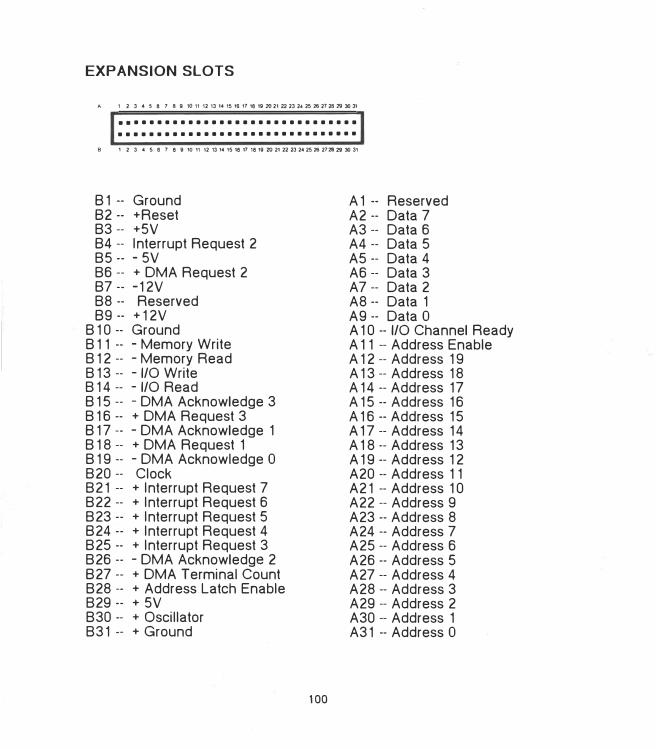
EXPANSION SLOTS
A 1 2 3 4 5 8 1 8 9 tO 11 12 13 1,4 15 16 17 18 19 20 21 22 23 2-4 25 26 27 28 29 30 31
.•.............................
...............................
B 1 2 3 4 5 15 7 8 9 10 11 12 13 14 15 18 17 1 8 19 20 2122 232425 26 2728 29 30 31
81 -- Ground 82 -- +Reset 83 -- +5V 84 -- Interrupt Request 2 85 -- - 5V 86 -- + OMA Request 2 87 -- .::.12V 88 -- Reserved 89-- +12V
8 10 -- Ground 8 11 -- - Memory Write 8 12 -- -Memory Read 8 13 -- -1/0 Write 814 -- -1/0 Read 815 -- - OMA Acknowledge 3 816 -- + OMA Request 3 817 -- - OMA Acknowledge 1 818 -- + OMA Request 1 819 -- - OMA Acknowledge O 820 -- Clock 821 -- + Interrupt Request 7 822 -- + Interrupt Request 6 823 -- + Interrupt Request 5 824 -- + Interrupt Request 4 825 -- + Interrupt Request 3 826 -- - OMA Acknowledge 2 827 -- + OMA Terminal Count 828 -- + Address Latch Enable 829 -- + 5V 830 -- + Oscillator 831 -- + Ground
100
A 1 -- Reserved A2 -- Data 7 A3 -- Data 6 A4 -- Data 5 AS -- Data 4 A6 -- Data 3 A7 -- Data 2 A8 -- Data 1 A9 -- Data O A 10 -- 1/0 Channel Ready A 11 -- Address Enable A 12 -- Address 19 A 13 -- Address 18 A 14 -- Address 17 A 15 -- Address 16 A 16 -- Address 15 A 17 -- Address 14 A 18 -- Address 13 A 19 -- Address 12 A20 -- Address 11 A21 -- Address 10 A22 -- Address 9 A23 -- Address 8 A24 -- Address 7 A25 -- Address 6 A26 -- Address 5 A27 -- Address 4 A28 -- Address 3 A29 -- Address 2 A30 -- Address 1 A31 -- Address O
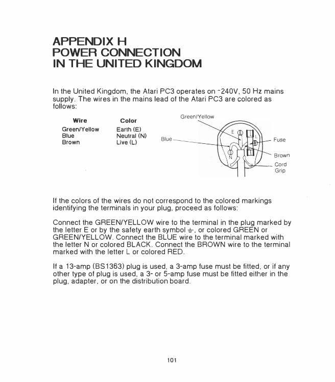
APPENDIX H
POWER CONNECTION
IN THE UNITED KINGDOM
In the United Kingdom. the Atari PC3 operates on -240V. 50 Hz mains supply. The wires in the mains lead of the Atari PC3 are colored as follows:
Wire
Green/Yellow Blue Brown
Color
Earth (E) Neutral (N) Live (L)
Blue
Green/Yellow
Fuse
Brown
---Cord Grip
If the colors of the wires do not correspond to the colored markings identifying the terminals in your plug, proceed as follows:
Connect the GREEN/YELLOW wire to the terminal in the plug marked by the letter E or by the safety earth symbol�. or colored GREEN or GREEN/YELLOW. Connect the BLUE wire to the terminal marked with the letter N or colored BLACK. Connect the BROWN wire to the terminal marked with the letter Lor colored RED.
If a 13-amp (BS 1363) plug is used. a 3-amp fuse must be fitted. or if any other type of plug is used, a 3- or 5-amp fuse must be fitted either in the plug, adapter. or on the distribution board.
101
GLOSSARY
access To retrieve data from storage.
alphanumeric keys The letter. number. and symbol keys on. the keyboard. The alphanumeric keys are positioned on the computer keyboard just as they are on a standard typewriter keyboard.
ANSI American National Standards Institute. This institute defines terminal emulation standards as well as other computer data standards.
application A program written to solve a specific problem or produce a specific result, and that can be executed by a computer. That is. the computer is "applied" to the task. (See program.)
AUTOEXEC.BAT AUTOmatically EXECuted BATch file. A file you create that automatically executes the commands it contains during system initialization.
back up To copy a disk or file. Backing up provides you with a good copy of a disk or file in case its information is damaged or lost.
batch file A file containing one or more commands. providing a convenient way to run those commands by entering the batch file name at the system prompt. Commands in the file execute sequentially until the file ends. (See AUTOEXEC.BAT file.)
bit The smallest unit of computer memory capable of representing ON or OFF. Eight bits equal one byte. (See byte.)
boot To begin the computer's operation. Booting is usually accomplished by switching on your system. (See coldstart and warmstart.)
boot disk The disk you use to boot your Atari PC3. The boot disk must contain the system files. (See system files.)
busy light The light on a disk drive that indicates it is reading from or writing to a disk.
103
byte A unit of computer memory. Each byte consists of eight bits. and is a unique character within the computer. For example. the letter "a" is stored in memory as one byte. (See bit and kilobyte.)
CGA Color Graphics Adapter. One of the available monitor display modes. CGA can be selected by the applications that use it, and gives you a maximum screen resolution of 640 pixels x 200 lines in monochrome or 320 pixels x 200 lines x 4 colors. (Compare to EGA, HGC, and MDA.)
CMOS RAM The nonvolatile (permanent) RAM in your real-time clock battery that keeps the correct date and time for your real-time clock.
coldstart Booting the computer by switching on the power. A coldstart is initiated while the computer is running by switching off the power for at least ten seconds, then switching it back on. A coldstart completely initializes the system. (Compare to warmstart.}
commands . Instructions for controlling MS-DOS or running programs.
CONFIG.SYS A file you can create that lets the operating system software be configured to your needs and recognize peripherals.
configuration A particular arrangement of peripherals on a computer system. or software installed to your preferences.
control keys Single keys or key combinations used to control computer operations. For example. the keys [Ctrl], [Alt]. and [Dell when pressed simultaneously as a key combination. restart the system.
copy To duplicate the information in a file. directory, or disk.
current directory The directory currently accessed. To identify the current directory, enter CD at the MS-DOS prompt. Each drive on your system can have a different (independent) current directory.
cursor A marker that appears on screen to indicate the position of the next action. The standard MS-DOS command line cursor is a blinking horizontal bar.
data file A collection of information used by an application.
104
default A value. option, or setting that the computer automatically selects until you direct it otherwise.
device See peripheral.
directory A list of files. (See root directory and working directory.)
disk drive The primary data storage device for your Atari PC3. The computer uses the disk drive to retrieve information from or store information on a disk.
DISKCOPY A command that duplicates data on one disk to another disk.
display mode commands Commands that change screen resolution and the number of available colors. (See CGA, EGA. HGC, and MDA.)
double-sided Having both sides of a disk's magnetic media certified as safe for storing data. A double-sided 5V4-inch disk stores up to 360 kilobytes of data; a double-sided 3Y2-inch disk stores up to 720 kilobytes.
EGA Enhanced Graphics Adapter. One of the available monitor display modes. EGA gives you a maximum resolution of 640 pixels x 350 lines x 16 selected colors from a palette of 64 colors. (Compare to CGA, HGC, and MDA.)
EGA video subsystem The chip on the Atari PC3's motherboard that lets you have EGA screen resolution and color selection. (See EGA.)
enter To instruct MS-DOS to run a command. To enter a command. type the command on the MS-DOS command line and press [Enter].
error message An on-screen message indicating that MS-DOS or an application is unable to process a command.
expansion board An integrated circuit board that expands or enhances the capabilities of a computer system. Hard disk controllers. network controllers. modems. and extra memory can all be supplied on expansion boards. You can add four expansion boards to your Atari PC3.
105
expansion slot A slot in a computer that accommodates an expansion board. The Atari PC3 has four expansion slots that accommodate PC XT-style boards.
extension The file type appended to the name of a file and separated from it with a period(.). An extension is optional and can have up to three characters. Some common extensions are .DOC, .TXT. and .BAT.
file A collection of information that can be stored on disk or held temporarily in RAM.
floppy disk The magnetic media used to store programs and information generated on the Atari PC3. The media is made of material similar to audio tape and is encased in a protective covering. The Atari PC3's internal disk drive uses 5V4-inch floppy disks. If you add an optional 3V2-inch floppy disk drive to your Atari PC3 system. you can use 3V2-inch disks.
format To set the patterns on a floppy disk that enable it to store information. Formatting erases any information previously stored on the disk.
function keys The keys [Fl] through [Fl OJ along the left edge of the Atari PC3 keyboard. These keys are used for special purposes in many applications.
GEM Graphics Environment Manager. A graphics-based operating environment that includes GEM Desktop, a desktop metaphor environment that lets the user "point and click" to execute and control programs and applications.
GEM Desktop A screen graphics representation of a desktop used for running GEM applications and some MS-DOS commands.
GEM Paint A design and paint program you can run from GEM Desktop.
GEM Write A word-processing program you can run from GEM Desktop.
hardware The actual physical apparatus of your computer system. (Compare to software.)
106
HGC Hercules Graphics Card. One of the available monitor display modes. HGC gives you a screen resolution of 720 pixels x 348 lines in monochrome graphics mode. or 80 characters (9 x 14 pixels each) x 25 lines in monochrome text mode. (Compare to CGA, EGA, and MDA.)
initialization The process that sets the computer to its starting configuration.
integrated circuit The circuitry ·contained in a microchip. The motherboard and expansion boards contain a number of microchips for performing specific functions. (See microchip.)
interface An electronic connection that allows communication between the computer and a peripheral.
interface cable A cable that connects the computer to a peripheral. or a peripheral to another peripheral.
interrupt channel A channel that a device (controller. interface, or peripheral) uses when it needs to interrupt an operation to communicate with the processor. Depending on the needs of your application. each device should have its own interrupt channel. The interrupt channels you can use on the Atari PC3 are identified as IR02 through IR07.
1/0 address The storage location the processor uses to exchange data between itself and a controller. interface. or peripheral. 1/0 addresses are expressed in hexadecimal (base 16).
jumper Clips that connect pins on a jumper block. The position of a jumper on the pins determines functions on the motherboard or an expansion board.
kilobyte 1.024 bytes of memory. (See byte.)
MDA Monochrome Display Adapter. One of the available monitor display modes. MDA gives you a screen resolution of 80 characters x 25 lines. (Compare to CGA, EGA, and HGC.)
megabyte One million bytes or 1,024 kilobytes of memory. (See byte and kilobyte.)
107
memory The electronic circuits that the Atari PC3 uses to store data and programs. There are two kinds of computer memory: RAM and ROM. RAM loses its data when the computer loses power; ROM retains its data whether the computer has power or not. (See RAM and ROM.)
microchip An integrated circuit contained in a small block. The microchips you install in your Atari PC3 have pins on their undersides that plug into sockets on the motherboard.
modem MOdulator/DEModulator. A device that enables you to establish a communication link between your computer and other computers and online information networks via telephone lines.
monitor See video display.
motherboard The integrated circuit board inside the Atari PC3 that includes the processor chip, RAM chips, the video subsystem. and sockets that car: accept additional optional chips.
mouse A small. hand-manipulated device connected to your Atari PC3 that controls the movement of a pointer within GEM. The mouse is used with GEM applications and some other programs specifically written to use a mouse.
MS-DOS Microsoft Disk Operating System. The software that coordinates all computer operations on the Atari PC3.
MS-DOS command line The line on screen containing the MS-DOS prompt, where you enter MS-DOS commands and the names of programs you want to run.
network board A board that enables your Atari PC3 to become part of a network of computers. Computers linked on a network can share hard disks, printers. and other peripherals.
numeric data processor An optional chip that performs math calculations normally done by the system's main processor (such as calculating spreadsheets). This processor has instructions that are carefully tuned for fast and accurate floating point calculations.
108
parallel interface An industry-standard interface that connects parallel printers and other parallel peripherals to the Atari PC3. The parallel interface sends and receives data eight bits at a time. The parallel interface port on the back of the Atari PC3 is labeled "Printer."
parameter Information entered with a command that specifies how the command will operate.
pathname A list of items that specify the path through the directories on disk to the current directory. A pathname contains a string of directories and a filename. separated by backslashes (for example. \ADS\TV\WKEND.TXT).
PC mode The Atari PC3's standard operating speed of 4.77 MHz. (Compare to turbo mode).
peripheral Any kind of exterior device. such as a disk drive. monitor. or printer. that you connect to your computer.
pixel A dot on the Atari PC3's video display. Pixels are arranged in a grid and set according to your monitor type and selected display mode. Pixel is short for picture element.
program A detailed and explicit set of instructions for accomplishing some purpose, expressed in a language that can be read by a computer. ( Compare to application.)
prompt Any symbol or message on screen indicating that the computer is awaiting input from the user. The default MS-DOS prompt is A> followed by a blinking horizontal bar.
RAM Random Access Memory. The part of the computer's memory that is used to write data to and read data from a disk. When you work with your Atari PC3. the information displayed on screen is in RAM. Information in RAM is lost when you switch off the computer. The Atari PC3 has 512 to 640 kilobytes of RAM depending on whether additional RAM chips have been added.
real-time clock A battery-operated clock inside the Atari PC3 that keeps the correct time and date regardless of whether the computer is on or off.
109
removable data cartridge drive A drive that uses removable highcapacity disk cartridges.
resolution The number of pixels on a monitor screen. More pixels mean crisper screen images. On the Atari PC3. you can change the resolution with the display mode commands. (See display mode commands.)
ROM Read Only Memory. The part of the computer's memory that is permanently recorded on a chip on the computer's motherboard. ROM contains the information needed to start and operate the computer and its peripherals. ROM cannot be altered and retains its factory programmed information with or without power to the computer. The Atari PC3 has 32 kilobytes of ROM.
root directory The main directory on every disk. In MS-DOS. the root directory is indicated by a backslash (\).
ATC Real-Time Clock. The Atari PC3's utility program that lets you set your real-time clock. (See real-time clock.)
scroll To display data that is longer than one screenful by rolling it up or down the screen.
sector A section of a track on a disk. On 5V4-inch disks, sectors are generally 512 bytes long. (See track.)
serial interface An industry-standard interface for connecting modems and other serial peripherals. A serial interface sends data one bit at a time. The serial interface on the back of the Atari PC3 is labeled "Serial."
software The programs and applications you run on your computer. (Compare to hardware.)
source disk The disk that information is written from during a DISKCOPY procedure. (Compare to target disk.)
startup disk See boot disk.
110
switch parameters Options that can be used with commands to control how MS-DOS performs the command. A forward slash(/) always precedes each switch parameter included with a command.
syntax The form used to enter commands correctly. Syntax tells you what elements follow a particular command. whether they are required or optional, and what punctuation must be used.
system files The files COMMAND.COM. 10.SYS, and MSDOS.SYS. which MS-DOS must read from a boot disk in order to boot. 10.SYS and MSDOS.SYS. if present. do not appear in the disk directory listing because they are hidden files.
system prompt The prompt on the command line that indicates that MS-DOS is ready to accept a command. For example. A> is the default prompt for drive A.
tape drive A drive that uses magnetic tape cartridges for backing up disk data.
target disk The disk that information is written to during a.DISKCOPY procedure. (Compare to source disk.)
track One of the patterns on a disk that contains the data written on the disk. Each track is made up of smaller sections called sectors. (See sector.)
tree structure The method MS-DOS uses for organizing directories. A tree-structured filing system has levels of directories that branch out from the root directory.
turbo mode The Atari PC3's fast (8.0 MHz) operating speed. In turbo mode. your system calculates. generates graphics. and saves and retrieves data more quickly than in standard PC mode. (Compare to PC mode.)
video display A video screen device used for viewing computer entries and responses.
warmstart Rebooting the computer by pressing [Ctrl) [Alt) [Dell A warmstart only partially initializes the system. (Compare to coldstart.)
111
wildcard A question mark (?) or asterisk (*) character used in a filename specification to specify the search criteria. ? matches one character; • matches any character to the end of the first name or extension.
write-protect To mechanically prevent a disk from being written to. To write-protect a 5V4-inch disk, place a write-protect tab over the notch. To write-protect a 3V2-inch disk. move the write-protect tab so you can see through the notch.
112
CUSTOMER SUPPORT
Atari Corporation welcomes inquiries about your Atari computer products. We also provide technical assistance. Write to Customer Relations at an address listed below.
Atari user groups also provide outstanding assistance. To receive a list of Atari user groups in your area, send a self-addressed, stamped envelope to an address below.
In the- United States, write to:
Atari Corporation Customer Relations P. 0. Box 61657Sunnyvale, CA 94088
In Canada.·write to:
Atari (Canada) Corp. 90 Gough Road Markham. Ontario Canada L3R 5V5
In the United Kingdom. write to:
Atari Corp. (UK) Ltd. P. 0. Box 555SloughBerkshire SL2 582
Please indicate User Group Lisi, Technical Assistance, or the subject of your letter on the outside of the envelope.
113
INDEX
A
A> prompt, 12. 22. 28-29Adaptec low-level formatting program.
App.E alphanumeric keys, 14 [Alt] key, 14 angle brackets. 37 ANSI standard terminal emulation, 23 applications. 19, 23, 25, 31 [Arrow] keys, 15 AUTOEXEC.BAT file, 23-24. 31, 33, 49,
51, 52 creating, 24
B
B> prompt, 28-29back panel, computer, 15-17backing up a hard disk. App. Ebackslash. 33, 34[Backspace] key, 14, 39BACKUP command. App. Ebackup disks. 10, 22-23.BAT files. 24-25batch files. 24-25battery, real-time clock, 29-30, App. Abrackets, 37
angle, 37 - square. 37
115
c
C> prompt, App. Ecable connectors, 15, App. A[Caps Lock] key, 14, 15caring for your system. App. ACGA command, 52-54CGA mode, 52-54CHOIR (CHange DIRectory) command,
24, 47-48 CHKDSK (CHecK DiSK) command, 24,
50-51CLICK command, 32 clock, real-time, 29-30, App. A CLS (Clear Screen) command. 56-57 coldstart. 13 colors, selecting, 54-55 command line, 12, 13, 14. 19, 28 command syntax, 37-38 commands, 19, 24. 25, 33
editing, 39 entering, 38 pausing, 14
computer back panel, 15-17 connecting, 7-10 right side panel, 17
Config switches. 8, 16 . CO NFIG.SYS file. 23, 33
creating, 23 configuring expansion boards. App. C connecting
external floppy disk drives. App. D peripherals, 15-17 the system. 7-10
connectors expansion slots. 17, App. C, App. G external floppy disk drive. 17. App. D. App.G internal floppy drive, App. C. App. G keyboard, 9. 10. 16. App. G monitor (video). 9, 16, App. G mouse. 16, App. G pinouts, App. G power. 8, 16 printer (parallel), 7. 15, App. G serial. 7. 16, App. G
control keys, 14 COPY command. 42-43, App. E copying
disks. 22-23, 40-41 files. 42-43
creating files. 24 [Ctrl] key. 14 · [Ctrl] [Alt] key. 14 [Ctrl] [Alt] [>] keys, 14. 32 [Ctrl] [Alt][<) keys, 14. 32 [Ctrl] [Alt] [1] keys, 31 [CtrlJ [Alt] [2) keys, 31 [Ctrl] [Alt] [Del] keys, 14, 54 [Ctrl] [Alt] [keypad+] keys, 14. 31 [Ctrl] [Alt] [keypad -] keys, 14, 31 [Ctrl] [Num Lock] keys, 14. 44 [Ctrl] [PrtSc] keys, 14 [Ctrl] [SJ keys, 14. 44 [Ctrl] [Scroll Lock] keys, 14 current directory. 24 cursor. 12. 15, 55-56 CURSOR command, 55-56
116
D
date prompt. 11. 29-30 default drive. 12 DEL (DELete) command. 45 [Del] key. 14 DEVICE command. 23. 33 DIR (DIRectory) command, 24, 37, 46 directory. 25, 26. 38, 46-48
changing, 47-48 checking, 50-51 creating, 25. 47 current. 24, 47-48 displaying, 46. 48 erasing, 48 naming, 26. 45, 47 root, 25
disk A. 19, 29 disk 8, 19, 29 DISKCOPY command, 22-23, 40-41 disk. floppy. 19. 20-23, 39-41
3Y2-inch. 19, 20-21 5Y•-inch. 19. 20-21 backup, 10, 22-23 checking. 20. 50-51 copying, 22-23, 40-41 erasing, 20 errors. 52 formatting, 20. 22. 39-40 inserting, 11, 20-21 labeling, 23 memory capacity. 20 preparing, 39-40 removing, 21 source. 22 storing, 22 target, 22 working, 10, 22-23 write-protecting, 21
disk drive. 5, 7, 17. 19, 28, 38 busy light. 21 connecting,App.C,App.D connector pinouts. App. G default. 12 external floppy, 7, 17, App. D external hard, 7 internal floppy, 5, 7, 8, 19, App. A. App.C internal hard, 5, 7. 19, App. C, App. E nonstandard. 23 port. 17. App. D removing, App. C startup, 12 working, 28-29
drive 0, 12 drive A, 12, 19. 28 drive 8, 12. 19, 28 drive C, 12, App. E drive designation
changing, 28-29 drive latch, 11, 20-21
E
editing commands, 39 editing keys, 13, 39 EGA command. 53 EGA mode, 32, 53 ellipsis. 37 [End] key, 14 [Enter] key, 11, 24, 33 entering commands. 33. 38 Epson low-level formatting program,
App.E ERASE command, 45 erasing
directories, 48 disks. 20, 40 files, 45
117
error messages Adaptec low-level formatting, App. E MS-DOS, 50, 57-59, App. A
[Esc] key, 14, 39 expansion boards, 6, 8, 17, App. A.
App.C configuring, App. C installing, App. C
expansion slots. 5, 17, App. C connector pinouts. App. G
extension. 26-28 reserved, 26
external floppy drive. 7. 17, App. D connector pinouts. App. G installing, App. D port. 17
F
If (file) switch, 48 If (fix) switch, 50 [F2] key, 12 [F3] key, 12 FDISK command, App. E file. 12. 25, 26, 42-45
checking, 50-51 copying, 42-43 dating, 12 erasing, 45 finding, 49 fragmented, 50 naming, 26-28 printing, 51 renaming, 44-45 saving, 25 viewing, 44
filename. 24, 26-28 reserved. 26
floppy drive controller. 7, App. C FORMAT command, 39-40. App. E
formatting floppy disks, 20. 22. 39. 40 hard disks. App. E
forward slash. 37 freezing a screen. 44 function keys, 13
G
GEM Desktop, 31. 33 GEM Paint, 31 GEM Write. 31
H
hard disk controller board, 6 hard disk drive. 6. 12. 19. App. E hardware. 5-7
care. App. A problems. App. A
HCOLOR command. 9, 53-55 HGC command, 9. 52-54 HGC mode, 9, 52-54 [Home] key. 14
1/0 address. App. C IBM PC XT computer. 6. 7. 17 indicator lights. 12. 15
[Caps Lock], 15 disk drive. 21 [Num Lock], 15 power. 10 (Scroll Lock], 15 turbo mode, 12. 30
initializing the system. 10-13, 23
118
(Ins] key. 14 Intel 8087 chip, 6, 12. 30-31. App. B
installing, App. B interference. radio or television reception,
16,App.A internal drives. 5, 7. 8, 19. App. C
connector pinouts. App. G floppy disk. 5, 7, 19. App. C hard disk. 5, 7, 19, App. C, App. E installing, App. C removing, App. C
interrupt channel. App. C
K
key click, 14. 32 key combinations. 14 keyboard. 6. 9. 13-15. 17. App. A
connecting, 9. 17 connector pinouts. App. G jack. 9, 17
keys, 13-15 alphanumeric. 13 [Arrow], 14
L
control. 14 editing, 13, 39 function. 13 numeric keypad. 15
labeling disks, 23 list device. 51 low-level formatting, App. E
M
magnetic media, 20, 23 MDA command, 9, 53 MDA mode. 52-54 microchips, 5 MKDIR (MaKe DIRectory) command. 47 MODE command. 52 modem. 6, 7, 16, 52 monitor. 6, 8-9. 16. 32. 52-55
Atari PCM124. 32 color. 6, 8, 16, 52 connecting, 8-9 connector pinouts. App. G EGA, 6, 8, 16, 52-54 monochrome. 6, 8, 16, 32, 52 port. 9, 16
monitor display modes, 32, 52-55 CGA 52-54 · com�ands, '52-55 EGA. 52-54 HGC, 52-54 MDA. 52-54 selecting, 32, 52-54
monitor type selection switches. 8, 54 setting, 8-9
motherboard. 5, App. C mouse, 6, 9. 11, 17. 33, App. A
connecting, 9 connector pinouts. App. G port. 9, 17
MOUSE command, 33 mouse driver file. installing, 33 MOUSE.COM, 33 MOUSE.SYS. 33 MS-DOS, 11.12.19, 23, 26 MS-DOS command line, 12, 13, 14, 19, 2 MS-DOS Disk 1. 10-12. 19, 22, 25. 52 MS-DOS Disk 2, 19, 52 MS-DOS prompt, 12. 19, 28-29 multi-drive system, 19, 29, 43
119
N
name. 26-28 network board, 6 [Num Lock] key, 14-15 numeric data processor. 6, 8, 12. 30-31
installing, App. B numeric entry. 14 numeric keypad, 15
0
OMTI low-level formatting program. App. E
on/off switch, computer. 13 one-drive system, 19, 28, 43 optional devices, 6-7
installing, 6 output, 14
p
/p (pause) switch. 38 PALETTE command, 54-55 parallel devices. 17
connector pinouts, App. G port. 7, 17.
parameters, 33-38 switch, 37-38
PATH command, 24. 49 pathname, 34-38
absolute. 34 relative, 34
pausing a command, 14 PC mode. 12. 14, 30-31 PCM 124 monitor (Atari). 32 peripherals, external, 10, 15-17
connecting, 10, 15-17 [Pg Dn] key, 14, 55
[Pg Up] key, 14, 55 pinouts. App. G pixels. 52 ports, 15-17
external floppy drive. 17 keyboard. 9, 16 monitor (video). 9, 16 mouse, 9, 16 power. 8, 16 printer. 7. 16 serial, 7, 16
power connection in the United Kingdom. App. G
power jack. computer. 8, 16 power supply. 5 power switch. 16 preparing disks. 20. 39-41 PRINT command. 24-25. 51 print queue buff er. 51 printer. 7, 14. 17. 51. 52
connector pinouts, App. G naming, 51. 52 port. 7. 15. 17
printing, 14. 51 program disks. 10, 22
backing up, 10, 22 prompt, 11
date. 11 system. 12. 19. 28-29. 56 time, 11
PROMPT command, 56 [PrtSc] key. 14
a
[QJ key, 55
120
R
RAM. 21, App. A. App. B system total, 6
RAM chips, optional. 6. 8, App. B installing, App. B testing, App. A
RAM disk, 23 real-time clock. 29-30. App. A
changing the battery, 29-30. App. A setting, 29-30
removable data cartridge drive, 7 REN (REName) command. 44-45 resolution. screen. 32. 52 RESTORE command. App. E right side panel. computer. 17 RMDIR (ReMove DIRectory) command,
48 root directory. 25. 33. 34 ATC command. 30
s
/s (system files) switch, 39 screen resolution. 31. 50 [Scroll Lock] key. 14. 15 scrolling, 14
freezing a screen. 44 sector. 20. 40 serial devices. 16. 52
connector pinouts. App. G port. 7. 16
setting up the system, 5-10 [Shill] key, 14 [Shift] [PrtSc] keys, 14 software care. App. A source disk. 22 [space Bar] key, 44 specifications. App. F square brackets, 37
startup drive, 12 choices. 12
static discharge, preventing, 15, App. B storing disks, 22 switch parameters. 37-38 switching off the system, 13 switching on the system, 10-12
problems. App. A syntax. command. 37-38 [Sys Req] key, 15 system components. 5-7 system maintenance, App. A system prompt, 12. 19, 28-29, 56 system speed, 12, 30-31
changing, 30-31 default, 30 setting, 14, 30-31
system status report. 50-51
T
It (terminate) switch, 51 [Tab] key. 14 tape drive. 7 target disk, 22 time prompt, 11, 29-30 track. 20 TREE command, 48 tree structure. 25 TURBO command, 31 turbo mode, 12. 14. 30-31
indicator light, 12. 30 TYPE command, 44
u
United Kingdom. power connection in. App. G
unpacking the system. 5
121
v
/v (view) switch. 50 /v (volume name) switch. 39 video display subsystem. 32. 52-55. App. c
video (monitor) port. 9, 16 connector pinouts. App. G
w
lw (wide) switch, 37, 38, 46 warmstart. 14, 54 wildcards. 27-28 working disk. 10. 22. 23, 29-30 working drive, 28-29 working environment. 5 write-protect notch, 11. 20-21 write-protecting disks. 21
x
XCOPY command, App. E
)l'-ATARr Copyright © 1988, Atari Corporation. Sunnyvale, CA 94086 All rights reserved . JI\. C300317-001 Rev. B
Printed in Taiwan
K. 1. 3. 1988