Embed Size (px)
Citation preview
Atlas Copco Torque Arms
Namnlöst-1 1 2/19/2013 10:46:26 AM
Contents PageIntroduction ......................................2TPS Controller .................................4TPS Positioning Torque Arms ..........5Torque arm SML T ...........................6Torque arm SMS T ..........................7Carbon arm SMC.............................8Linear arm SML MK II ......................9MicroTorque GHP ..........................10Position Recognition System .........15Articulated arm ..............................16Balancer HRIL ...............................19Balancer RIL ..................................20Balancer COLIBRI .........................21Balancer WP ..................................22
Torque arms
Torquearms-Cat-2013.indd 1 2/19/2013 10:31:23 AM
2
Introduction – Torque arms
Straight Pistol AngleErgonomical > 4 Nm > 7 Nm > 30 Nmoptimized*Conventional > 3 Nm > 5 Nm > 20 Nmtools
Protect your most valuable resource
Operator health is important. If your operators work with hand-held electric or pneumatic tools, the last thing you want is for their health to suffer. However light the tool, when an operator performs repetitive tasks daily, often with incorrect posture, the tool seems to grow heavier by the hour. Add torque reaction from the tightening pro cess, and the result can be hand-arm-shoulder disorders that may lead to injury and even premature retirement.
Payback within one yearAlthough the plant only operates on a single-shift basis, Lemken recouped its investment within one year. The com-pany is satisfied with the equipment and enthusiastic about the flexibility of Atlas Copco tools.
Basic guidelines for torque armsTools used full days with a torque capac-ity shown in the table should always be used together with a torque arm in order to prevent work related injuries.
To considerlHowever light or low torque, daily use
of tools for repetitive tasks can result in hand-arm-shoulder disorders.
lOn average a female operator can take 2/3 of the same force as her male colleague.
lIs there enough space for a torque arm at the workplace.
lFinished product quality improvement.lWith the use of a torque arm the arm
will absorb all the reaction forece from the tool and prevent the tool from spin-ning around its axis. To ensure highest possible accuracy of the clamp force a torque arm should be used to prevent movement of the tool.
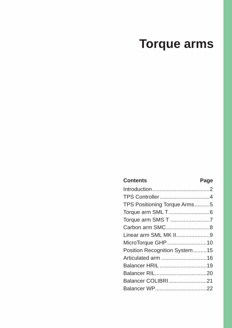
Give your operators an extra arm! Atlas Copco torque arms are labour-saving extensions of Atlas Copco hand-held tools that ensure accurate tightening, and raise individual productivity in your plant. Available for torques of up to 1000 Nm, these ingenious constructions are the perfect way to lighten the load when performing repetitive tasks on lines or benches.
Ease the strainAtlas Copco torque arms take the strain off your operators, and allow maximum freedom of movement and flexibility. Wide fields of reach mean that the op-erator has a large working area without stretching.
Fast paybackInvesting in torque arms is not such a major decision. With their benefits in terms of increased productivity and im-proved employee health, payback time is short.
Linear torque arms raise productivity in GermanyAt its plant in Alpen, in the lower Rhine area of Germany, Lemken GmbH & Co. KG manufactures agricultural machin-ery. Previously, a safety critical bearing block joint was tightened using an impact wrench, followed by a torque wrench to reach final torque. The torque values required were between 300 and 500 Nm.
SML torque arms absorb reaction forcesTo improve productivity, Lemken installed an Atlas Copco Tensor DS electric angle nutrunner, mounted on SML 500 linear torque arms, to handle the task. The bolt is tightened to 300 Nm, then loosened 15 degrees and finally tightened to 300 Nm again. The SML 500 absorbs all re-action forces, and enables fast, accurate tightening, with good ergonomics for the operator.
How to order torque armThe max torque and weight of the tool determine the size of the torque arm. All tool holders are ordered separately. Choose a suitable tool holder for the torque arm and the tool to be used.
* Ergonomically optimized tools is electric tools with two step softstop, turbotight or fast clutch pneumatic tool on a hard joint.
Torquearms-Cat-2013.indd 2 2/19/2013 10:31:38 AM
3
Introduction
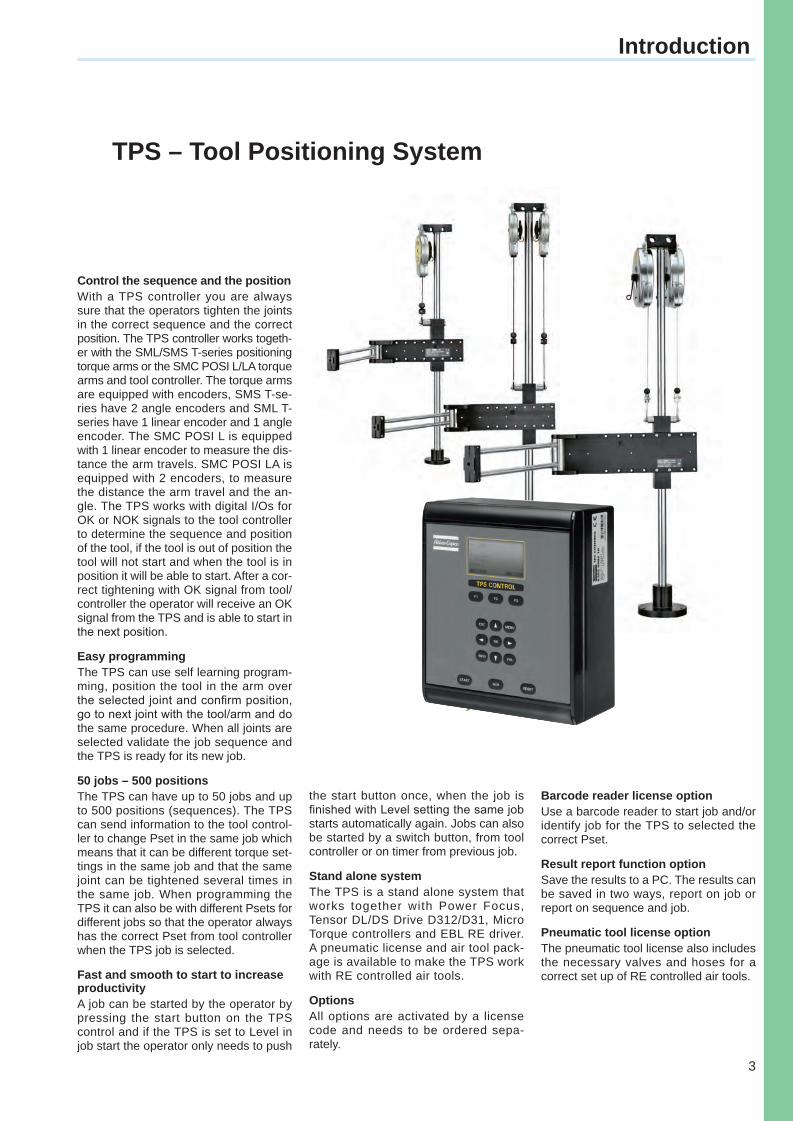
TPS – Tool Positioning System
Control the sequence and the positionWith a TPS controller you are always sure that the operators tighten the joints in the correct sequence and the correct position. The TPS controller works togeth-er with the SML/SMS T-series positioning torque arms or the SMC POSI L/LA torque arms and tool controller. The torque arms are equipped with encoders, SMS T-se-ries have 2 angle encoders and SML T-series have 1 linear encoder and 1 angle encoder. The SMC POSI L is equipped with 1 linear encoder to measure the dis-tance the arm travels. SMC POSI LA is equipped with 2 encoders, to measure the distance the arm travel and the an-gle. The TPS works with digital I/Os for OK or NOK signals to the tool controller to determine the sequence and position of the tool, if the tool is out of position the tool will not start and when the tool is in position it will be able to start. After a cor-rect tightening with OK signal from tool/controller the operator will receive an OK signal from the TPS and is able to start in the next position.
Easy programmingThe TPS can use self learning program-ming, position the tool in the arm over the selected joint and confi rm position, go to next joint with the tool/arm and do the same procedure. When all joints are selected validate the job sequence and the TPS is ready for its new job.
50 jobs – 500 positionsThe TPS can have up to 50 jobs and up to 500 positions (sequences). The TPS can send information to the tool control-ler to change Pset in the same job which means that it can be different torque set-tings in the same job and that the same joint can be tightened several times in the same job. When programming the TPS it can also be with different Psets for different jobs so that the operator always has the correct Pset from tool controller when the TPS job is selected.
Fast and smooth to start to increase productivityA job can be started by the operator by pressing the start button on the TPS control and if the TPS is set to Level in job start the operator only needs to push
the start button once, when the job is fi nished with Level setting the same job starts automatically again. Jobs can also be started by a switch button, from tool controller or on timer from previous job.
Stand alone systemThe TPS is a stand alone system that works together with Power Focus, Tensor DL/DS Drive D312/D31, Micro Torque controllers and EBL RE driver. A pneumatic license and air tool pack-age is available to make the TPS work with RE controlled air tools.
OptionsAll options are activated by a license code and needs to be ordered sepa-rately.
Barcode reader license optionUse a barcode reader to start job and/or identify job for the TPS to selected the correct Pset.
Result report function optionSave the results to a PC. The results can be saved in two ways, report on job or report on sequence and job.
Pneumatic tool license optionThe pneumatic tool license also includes the necessary valves and hoses for a correct set up of RE controlled air tools.
Torquearms-Cat-2013.indd 3 2/19/2013 10:31:46 AM
4
TPS Controller
Model Ordering No.Barcode license 4390 2045 00Pneumatic license 4390 2046 00Reporting license 4390 2047 00
Model Ordering No.TPS Controller 8202 9004 10
Options
Cables
Model Ordering No.Cable TPS to controller Power Focus/Tensor3 m 4222 1715 0310 m 4222 1715 10Cable TPS to EBL RE driver1.5 m 4222 1733 013 m 4222 1733 03Cable TPS to controller G41.5 m 4222 1734 013 m 4222 1734 03Cable TPS to controller MTF4001.5 m 4222 1735 013 m 4222 1735 03TPS Open End cable3 m 4222 1743 0310 m 4222 1743 10
TPS Controller
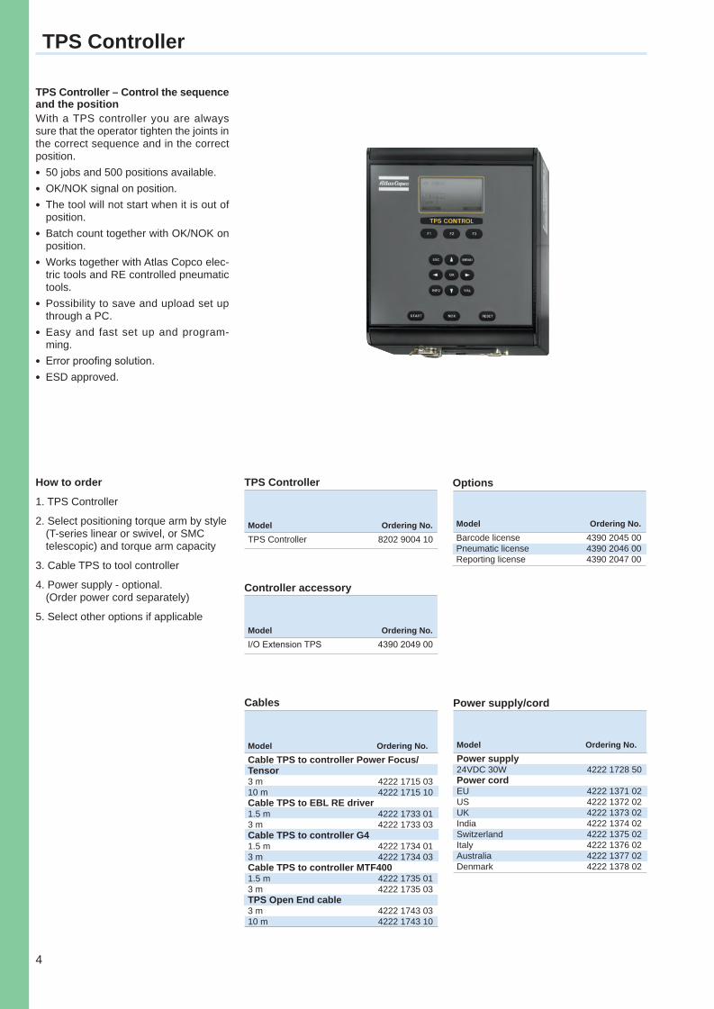
TPS Controller – Control the sequence and the positionWith a TPS controller you are always sure that the operator tighten the joints in the correct sequence and in the correct position.l 50 jobs and 500 positions available.l OK/NOK signal on position.l The tool will not start when it is out of
position.l Batch count together with OK/NOK on
position.l Works together with Atlas Copco elec-
tric tools and RE controlled pneumatic tools.
l Possibility to save and upload set up through a PC.
l Easy and fast set up and program-ming.
l Error proofing solution.l ESD approved.
Power supply/cord
Model Ordering No.Power supply24VDC 30W 4222 1728 50Power cordEU 4222 1371 02US 4222 1372 02UK 4222 1373 02India 4222 1374 02Switzerland 4222 1375 02Italy 4222 1376 02Australia 4222 1377 02Denmark 4222 1378 02
How to order
1. TPS Controller
2. Select positioning torque arm by style (T-series linear or swivel, or SMC telescopic) and torque arm capacity
3. Cable TPS to tool controller
4. Power supply - optional. (Order power cord separately)
5. Select other options if applicable
Controller accessory
Model Ordering No.I/O Extension TPS 4390 2049 00
Torquearms-Cat-2013.indd 4 2/19/2013 10:31:52 AM
5
TPS Positioning Torque Arms
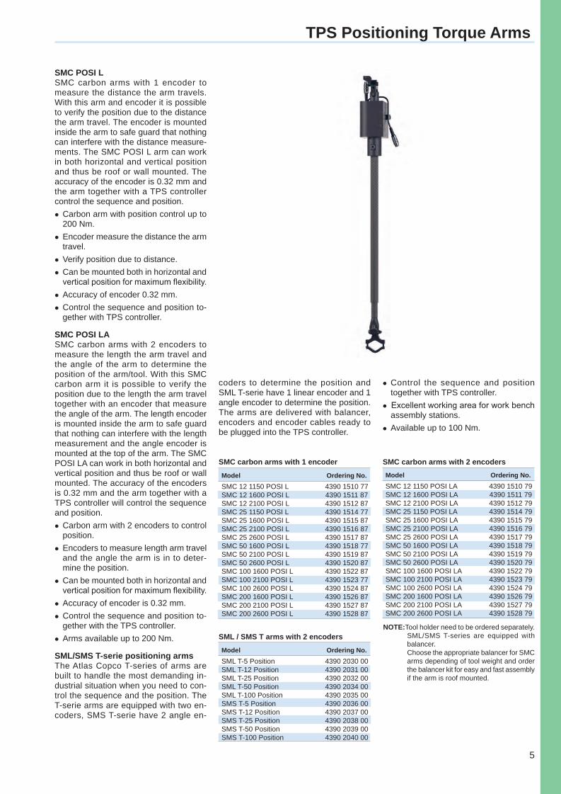
SMC POSI LSMC carbon arms with 1 encoder to measure the distance the arm travels. With this arm and encoder it is possible to verify the position due to the distance the arm travel. The encoder is mounted inside the arm to safe guard that nothing can interfere with the distance measure-ments. The SMC POSI L arm can work in both horizontal and vertical position and thus be roof or wall mounted. The accuracy of the encoder is 0.32 mm and the arm together with a TPS controller control the sequence and position.lCarbon arm with position control up to
200 Nm.lEncoder measure the distance the arm
travel.lVerify position due to distance.lCan be mounted both in horizontal and
vertical position for maximum flexibility. lAccuracy of encoder 0.32 mm.lControl the sequence and position to-
gether with TPS controller.
SMC POSI LASMC carbon arms with 2 encoders to measure the length the arm travel and the angle of the arm to determine the position of the arm/tool. With this SMC carbon arm it is possible to verify the position due to the length the arm travel together with an encoder that measure the angle of the arm. The length encoder is mounted inside the arm to safe guard that nothing can interfere with the length measurement and the angle encoder is mounted at the top of the arm. The SMC POSI LA can work in both horizontal and vertical position and thus be roof or wall mounted. The accuracy of the encoders is 0.32 mm and the arm together with a TPS controller will control the sequence and position.lCarbon arm with 2 encoders to control
position.lEncoders to measure length arm travel
and the angle the arm is in to deter-mine the position.
lCan be mounted both in horizontal and vertical position for maximum flexibility.
lAccuracy of encoder is 0.32 mm.lControl the sequence and position to-
gether with the TPS controller.lArms available up to 200 Nm.
SML/SMS T-serie positioning armsThe Atlas Copco T-series of arms are built to handle the most demanding in-dustrial situation when you need to con-trol the sequence and the position. The T-serie arms are equipped with two en-coders, SMS T-serie have 2 angle en-
coders to determine the position and SML T-serie have 1 linear encoder and 1 angle encoder to determine the position. The arms are delivered with balancer, encoders and encoder cables ready to be plugged into the TPS controller.
lControl the sequence and position together with TPS controller.
l Excellent working area for work bench assembly stations.
lAvailable up to 100 Nm.
Model Ordering No.SMC 12 1150 POSI L 4390 1510 77SMC 12 1600 POSI L 4390 1511 87SMC 12 2100 POSI L 4390 1512 87SMC 25 1150 POSI L 4390 1514 77SMC 25 1600 POSI L 4390 1515 87SMC 25 2100 POSI L 4390 1516 87SMC 25 2600 POSI L 4390 1517 87SMC 50 1600 POSI L 4390 1518 77SMC 50 2100 POSI L 4390 1519 87SMC 50 2600 POSI L 4390 1520 87SMC 100 1600 POSI L 4390 1522 87SMC 100 2100 POSI L 4390 1523 77SMC 100 2600 POSI L 4390 1524 87SMC 200 1600 POSI L 4390 1526 87SMC 200 2100 POSI L 4390 1527 87SMC 200 2600 POSI L 4390 1528 87
SMC carbon arms with 1 encoder SMC carbon arms with 2 encoders
SML / SMS T arms with 2 encoders
Model Ordering No.SML T-5 Position 4390 2030 00SML T-12 Position 4390 2031 00SML T-25 Position 4390 2032 00SML T-50 Position 4390 2034 00SML T-100 Position 4390 2035 00SMS T-5 Position 4390 2036 00SMS T-12 Position 4390 2037 00SMS T-25 Position 4390 2038 00SMS T-50 Position 4390 2039 00SMS T-100 Position 4390 2040 00
NOTE: Tool holder need to be ordered separately. SML/SMS T-series are equipped with balancer.Choose the appropriate balancer for SMC arms depending of tool weight and order the balancer kit for easy and fast assembly if the arm is roof mounted.
Model Ordering No.SMC 12 1150 POSI LA 4390 1510 79SMC 12 1600 POSI LA 4390 1511 79SMC 12 2100 POSI LA 4390 1512 79SMC 25 1150 POSI LA 4390 1514 79SMC 25 1600 POSI LA 4390 1515 79SMC 25 2100 POSI LA 4390 1516 79SMC 25 2600 POSI LA 4390 1517 79SMC 50 1600 POSI LA 4390 1518 79SMC 50 2100 POSI LA 4390 1519 79SMC 50 2600 POSI LA 4390 1520 79SMC 100 1600 POSI LA 4390 1522 79SMC 100 2100 POSI LA 4390 1523 79SMC 100 2600 POSI LA 4390 1524 79SMC 200 1600 POSI LA 4390 1526 79SMC 200 2100 POSI LA 4390 1527 79SMC 200 2600 POSI LA 4390 1528 79
Torquearms-Cat-2013.indd 5 2/19/2013 10:31:53 AM
6
C
A
B
C
A
B
Torque Arm SML T
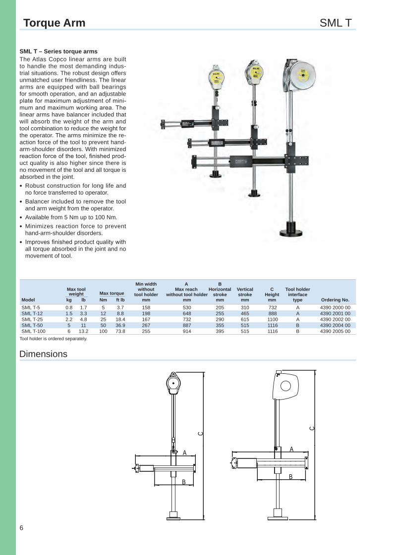
SML T – Series torque armsThe Atlas Copco linear arms are built to handle the most demanding indus-trial situations. The robust design offers unmatched user friendliness. The linear arms are equipped with ball bearings for smooth operation, and an adjustable plate for maximum adjustment of mini-mum and maximum working area. The linear arms have balancer included that will absorb the weight of the arm and tool combination to reduce the weight for the operator. The arms minimize the re-action force of the tool to prevent hand-arm-shoulder disorders. With minimized reaction force of the tool, fi nished prod-uct quality is also higher since there is no movement of the tool and all torque is absorbed in the joint. l Robust construction for long life and
no force transferred to operator.l Balancer included to remove the tool
and arm weight from the operator.l Available from 5 Nm up to 100 Nm. l Minimizes reaction force to prevent
hand-arm-shoulder disorders.l Improves fi nished product quality with
all torque absorbed in the joint and no movement of tool.
Dimensions
Tool holder is ordered separately.
Min width A B Max tool without Max reach Horizontal Vertical C Tool holder weight Max torque tool holder without tool holder stroke stroke Height interface Model kg lb Nm ft lb mm mm mm mm mm type Ordering No.SML T-5 0.8 1.7 5 3.7 158 530 205 310 732 A 4390 2000 00SML T-12 1.5 3.3 12 8.8 198 648 255 465 888 A 4390 2001 00SML T-25 2.2 4.8 25 18.4 167 732 290 615 1100 A 4390 2002 00SML T-50 5 11 50 36.9 267 887 355 515 1116 B 4390 2004 00SML T-100 6 13.2 100 73.8 255 914 395 515 1116 B 4390 2005 00
Torquearms-Cat-2013.indd 6 2/19/2013 10:31:58 AM
7
1200D
B
CA
SMS T Torque Arm
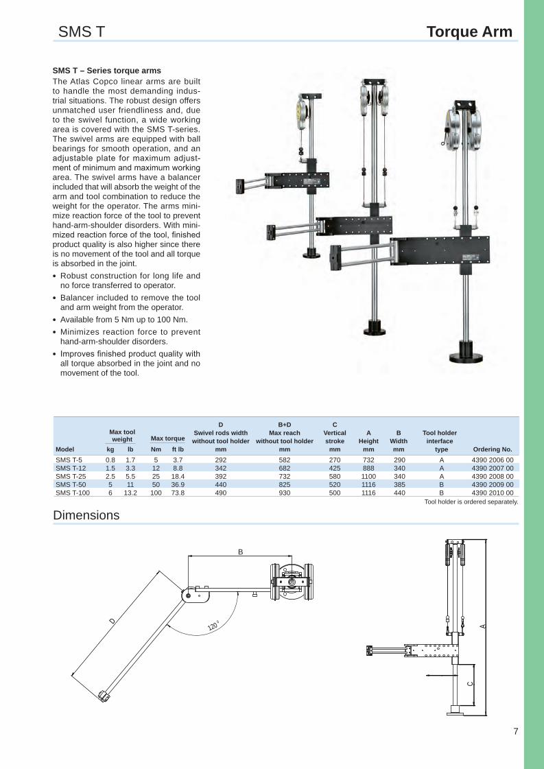
SMS T – Series torque armsThe Atlas Copco linear arms are built to handle the most demanding indus-trial situations. The robust design offers unmatched user friendliness and, due to the swivel function, a wide working area is covered with the SMS T-series. The swivel arms are equipped with ball bearings for smooth operation, and an adjustable plate for maximum adjust-ment of minimum and maximum working area. The swivel arms have a balancer included that will absorb the weight of the arm and tool combination to reduce the weight for the operator. The arms mini-mize reaction force of the tool to prevent hand-arm-shoulder disorders. With mini-mized reaction force of the tool, fi nished product quality is also higher since there is no movement of the tool and all torque is absorbed in the joint.l Robust construction for long life and
no force transferred to operator.l Balancer included to remove the tool
and arm weight from the operator.l Available from 5 Nm up to 100 Nm.l Minimizes reaction force to prevent
hand-arm-shoulder disorders.l Improves fi nished product quality with
all torque absorbed in the joint and no movement of the tool.
DimensionsTool holder is ordered separately.
D B+D C Max tool Swivel rods width Max reach Vertical A B Tool holder weight Max torque without tool holder without tool holder stroke Height Width interfaceModel kg lb Nm ft lb mm mm mm mm mm type Ordering No.SMS T-5 0.8 1.7 5 3.7 292 582 270 732 290 A 4390 2006 00SMS T-12 1.5 3.3 12 8.8 342 682 425 888 340 A 4390 2007 00SMS T-25 2.5 5.5 25 18.4 392 732 580 1100 340 A 4390 2008 00SMS T-50 5 11 50 36.9 440 825 520 1116 385 B 4390 2009 00SMS T-100 6 13.2 100 73.8 490 930 500 1116 440 B 4390 2010 00
Torquearms-Cat-2013.indd 7 2/19/2013 10:32:01 AM
8
A
A
Working area
Carbon Arm SMC
Dimensions
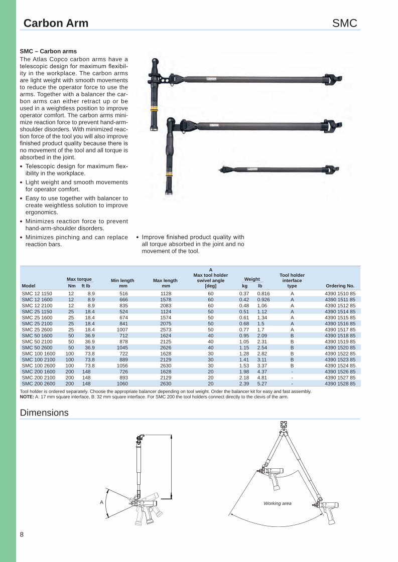
SMC – Carbon armsThe Atlas Copco carbon arms have a telescopic design for maximum fl exibil-ity in the workplace. The carbon arms are light weight with smooth movements to reduce the operator force to use the arms. Together with a balancer the car-bon arms can either retract up or be used in a weightless position to improve operator comfort. The carbon arms mini-mize reaction force to prevent hand-arm-shoulder disorders. With minimized reac-tion force of the tool you will also improve fi nished product quality because there is no movement of the tool and all torque is absorbed in the joint.l Telescopic design for maximum flex-
ibility in the workplace.l Light weight and smooth movements
for operator comfort.l Easy to use together with balancer to
create weightless solution to improve ergonomics.
l Minimizes reaction force to prevent hand-arm-shoulder disorders.
l Minimizes pinching and can replace reaction bars.
Tool holder is ordered separately. Choose the appropriate balancer depending on tool weight. Order the balancer kit for easy and fast assembly.NOTE: A: 17 mm square interface, B: 32 mm square interface. For SMC 200 the tool holders connect directly to the clevis of the arm.
A Max tool holder Tool holder Max torque Min length Max length swivel angle Weight interface Model Nm ft lb mm mm [deg] kg lb type Ordering No.SMC 12 1150 12 8.9 516 1128 60 0.37 0.816 A 4390 1510 85SMC 12 1600 12 8.9 666 1578 60 0.42 0.926 A 4390 1511 85SMC 12 2100 12 8.9 835 2083 60 0.48 1.06 A 4390 1512 85SMC 25 1150 25 18.4 524 1124 50 0.51 1.12 A 4390 1514 85SMC 25 1600 25 18.4 674 1574 50 0.61 1.34 A 4390 1515 85SMC 25 2100 25 18.4 841 2075 50 0.68 1.5 A 4390 1516 85SMC 25 2600 25 18.4 1007 2573 50 0.77 1.7 A 4390 1517 85SMC 50 1600 50 36.9 712 1624 40 0.95 2.09 B 4390 1518 85SMC 50 2100 50 36.9 878 2125 40 1.05 2.31 B 4390 1519 85SMC 50 2600 50 36.9 1045 2626 40 1.15 2.54 B 4390 1520 85SMC 100 1600 100 73.8 722 1628 30 1.28 2.82 B 4390 1522 85SMC 100 2100 100 73.8 889 2129 30 1.41 3.11 B 4390 1523 85SMC 100 2600 100 73.8 1056 2630 30 1.53 3.37 B 4390 1524 85SMC 200 1600 200 148 726 1628 20 1.98 4.37 - 4390 1526 85SMC 200 2100 200 148 893 2129 20 2.18 4.81 - 4390 1527 85SMC 200 2600 200 148 1060 2630 20 2.39 5.27 - 4390 1528 85
l Improve fi nished product quality with all torque absorbed in the joint and no movement of the tool.
Torquearms-Cat-2013.indd 8 2/19/2013 10:32:03 AM
9
360°
A
C
D
B
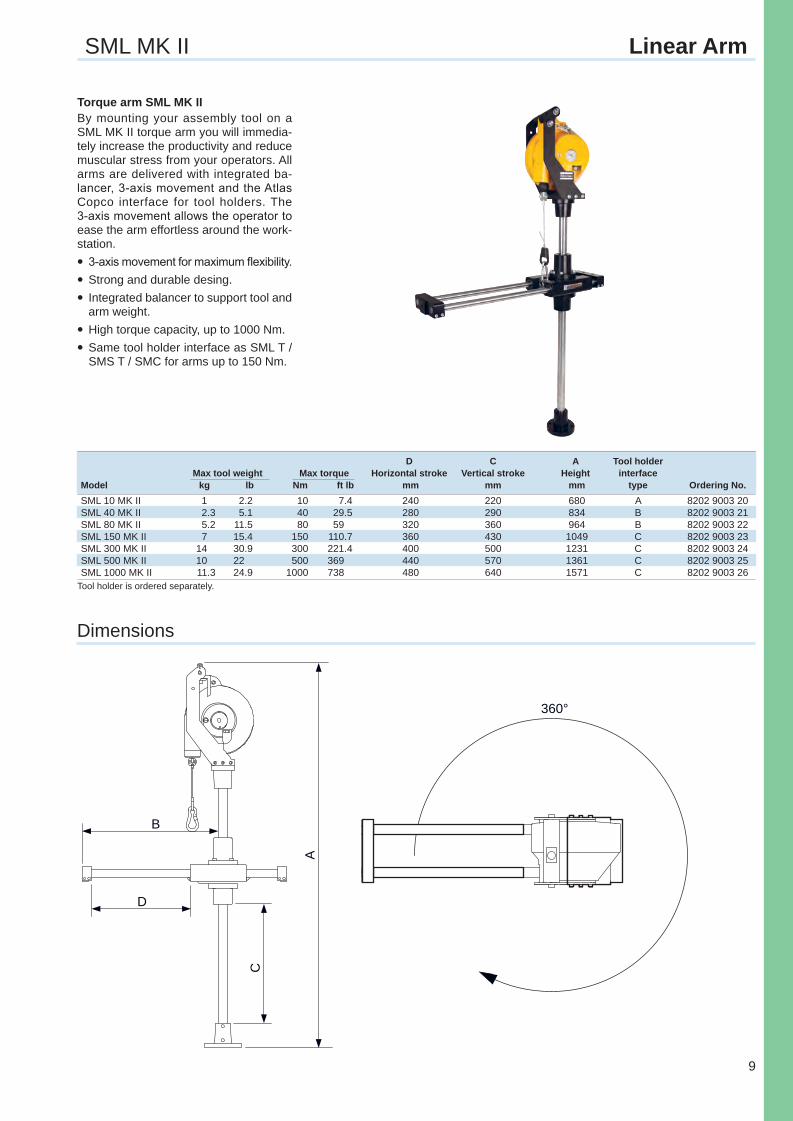
D C A Tool holder Max tool weight Max torque Horizontal stroke Vertical stroke Height interface Model kg lb Nm ft lb mm mm mm type Ordering No.SML 10 MK II 1 2.2 10 7.4 240 220 680 A 8202 9003 20SML 40 MK II 2.3 5.1 40 29.5 280 290 834 B 8202 9003 21SML 80 MK II 5.2 11.5 80 59 320 360 964 B 8202 9003 22SML 150 MK II 7 15.4 150 110.7 360 430 1049 C 8202 9003 23SML 300 MK II 14 30.9 300 221.4 400 500 1231 C 8202 9003 24SML 500 MK II 10 22 500 369 440 570 1361 C 8202 9003 25SML 1000 MK II 11.3 24.9 1000 738 480 640 1571 C 8202 9003 26
Torque arm SML MK IIBy mounting your assembly tool on a SML MK II torque arm you will immedia-tely increase the productivity and reduce muscular stress from your operators. All arms are delivered with integrated ba-lancer, 3-axis movement and the Atlas Copco interface for tool holders. The 3-axis movement allows the operator to ease the arm effortless around the work-station.l3-axis movement for maximum flexibility.lStrong and durable desing.lIntegrated balancer to support tool and
arm weight.lHigh torque capacity, up to 1000 Nm.lSame tool holder interface as SML T /
SMS T / SMC for arms up to 150 Nm.
SML MK II Linear Arm
Dimensions
Tool holder is ordered separately.
Torquearms-Cat-2013.indd 9 2/19/2013 10:32:04 AM
10
A
470
B
A
B
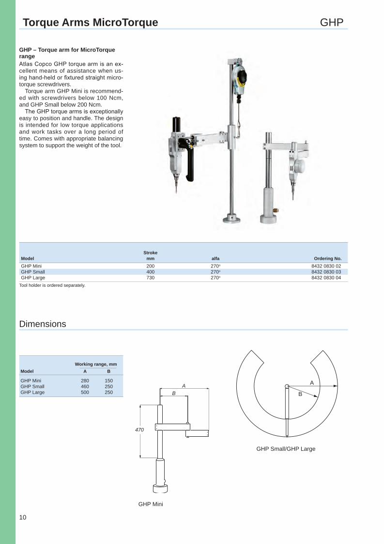
GHP – Torque arm for MicroTorque rangeAtlas Copco GHP torque arm is an ex-cellent means of assistance when us-ing hand-held or fi xtured straight micro-torque screwdrivers.
Torque arm GHP Mini is recommend-ed with screwdrivers below 100 Ncm, and GHP Small below 200 Ncm.
The GHP torque arms is exceptionally easy to position and handle. The design is intended for low torque applications and work tasks over a long period of time. Comes with appropriate balancing system to support the weight of the tool.
Stroke Model mm alfa Ordering No.GHP Mini 200 270o 8432 0830 02GHP Small 400 270o 8432 0830 03GHP Large 730 270o 8432 0830 04
GHP Mini
Torque Arms MicroTorque GHP
Dimensions
GHP Small/GHP Large
Working range, mmModel A B
GHP Mini 280 150GHP Small 460 250GHP Large 500 250
Tool holder is ordered separately.
Torquearms-Cat-2013.indd 10 2/19/2013 10:32:06 AM
11
Torque Arm Accessories
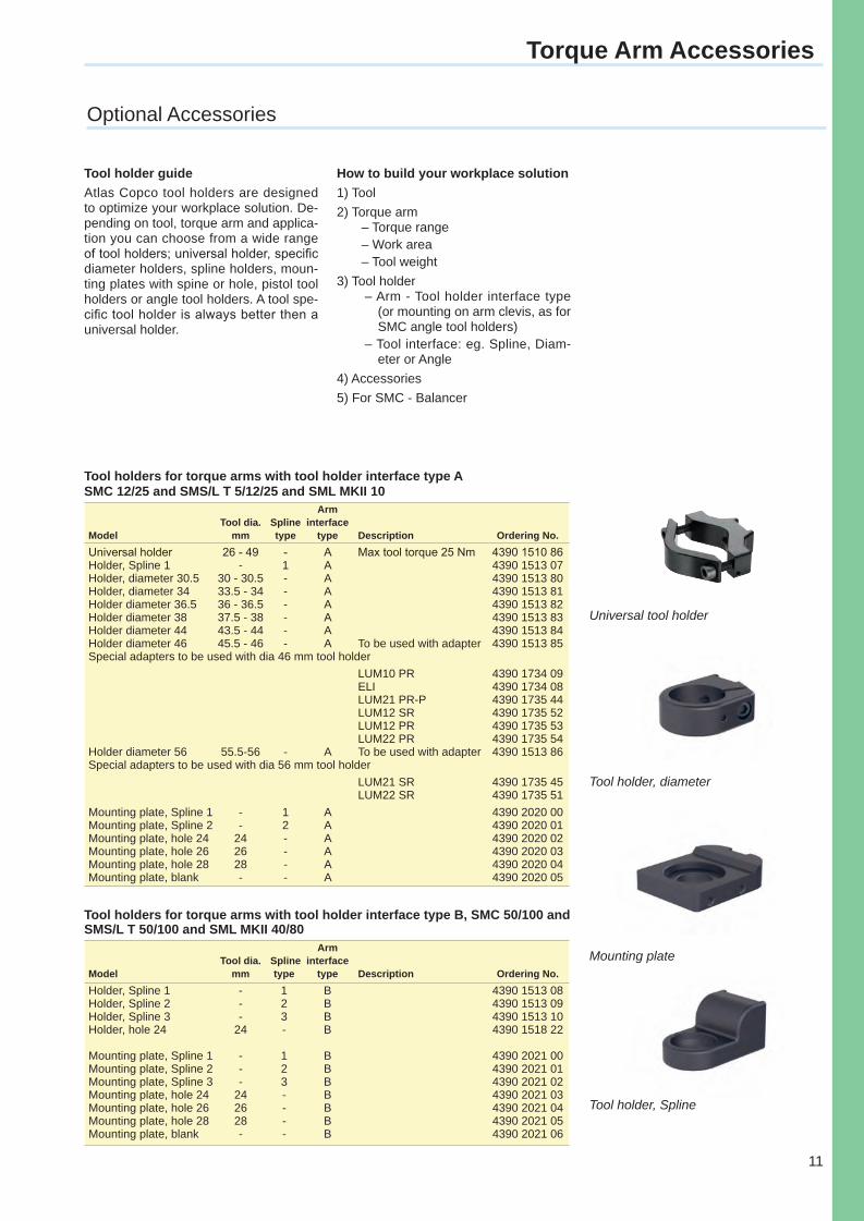
Arm Tool dia. Spline interface Model mm type type Description Ordering No.Universal holder 26 - 49 - A Max tool torque 25 Nm 4390 1510 86Holder, Spline 1 - 1 A 4390 1513 07Holder, diameter 30.5 30 - 30.5 - A 4390 1513 80Holder, diameter 34 33.5 - 34 - A 4390 1513 81Holder diameter 36.5 36 - 36.5 - A 4390 1513 82Holder diameter 38 37.5 - 38 - A 4390 1513 83Holder diameter 44 43.5 - 44 - A 4390 1513 84Holder diameter 46 45.5 - 46 - A To be used with adapter 4390 1513 85Special adapters to be used with dia 46 mm tool holder
LUM10 PR 4390 1734 09 ELI 4390 1734 08 LUM21 PR-P 4390 1735 44 LUM12 SR 4390 1735 52 LUM12 PR 4390 1735 53 LUM22 PR 4390 1735 54Holder diameter 56 55.5-56 - A To be used with adapter 4390 1513 86Special adapters to be used with dia 56 mm tool holder
LUM21 SR 4390 1735 45 LUM22 SR 4390 1735 51Mounting plate, Spline 1 - 1 A 4390 2020 00Mounting plate, Spline 2 - 2 A 4390 2020 01Mounting plate, hole 24 24 - A 4390 2020 02Mounting plate, hole 26 26 - A 4390 2020 03Mounting plate, hole 28 28 - A 4390 2020 04Mounting plate, blank - - A 4390 2020 05
Tool holders for torque arms with tool holder interface type ASMC 12/25 and SMS/L T 5/12/25 and SML MKII 10
Tool holders for torque arms with tool holder interface type B, SMC 50/100 and SMS/L T 50/100 and SML MKII 40/80 Arm Tool dia. Spline interface Model mm type type Description Ordering No.Holder, Spline 1 - 1 B 4390 1513 08Holder, Spline 2 - 2 B 4390 1513 09Holder, Spline 3 - 3 B 4390 1513 10Holder, hole 24 24 - B 4390 1518 22 Mounting plate, Spline 1 - 1 B 4390 2021 00Mounting plate, Spline 2 - 2 B 4390 2021 01Mounting plate, Spline 3 - 3 B 4390 2021 02Mounting plate, hole 24 24 - B 4390 2021 03Mounting plate, hole 26 26 - B 4390 2021 04Mounting plate, hole 28 28 - B 4390 2021 05Mounting plate, blank - - B 4390 2021 06
Optional Accessories
Universal tool holder
Tool holder, diameter
Tool holder guideAtlas Copco tool holders are designed to optimize your workplace solution. De-pending on tool, torque arm and applica-tion you can choose from a wide range of tool holders; universal holder, specific diameter holders, spline holders, moun-ting plates with spine or hole, pistol tool holders or angle tool holders. A tool spe-cific tool holder is always better then a universal holder.
How to build your workplace solution1) Tool2) Torque arm
– Torque range– Work area– Tool weight
3) Tool holder– Arm - Tool holder interface type
(or mounting on arm clevis, as for SMC angle tool holders)
– Tool interface: eg. Spline, Diam-eter or Angle
4) Accessories5) For SMC - Balancer
Mounting plate
Tool holder, Spline
Torquearms-Cat-2013.indd 11 2/19/2013 10:32:10 AM
12
Torque Arm Accessories
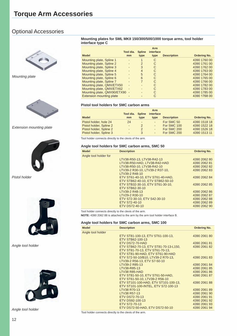
Mounting plates for SML MKII 150/300/500/1000 torque arms, tool holder interface type C Arm Tool dia. Spline interface Model mm type type Description Ordering No.Mounting plate, Spline 1 - 1 C 4390 1760 00Mounting plate, Spline 2 - 2 C 4390 1761 00Mounting plate, Spline 3 - 3 C 4390 1762 00Mounting plate, Spline 4 - 4 C 4390 1763 00Mounting plate, Spline 5 - 5 C 4390 1764 00Mounting plate, Spline 6 - 6 C 4390 1765 00Mounting plate, Spline 7 - 7 C 4390 1766 00Mounting plate, QMX/ETX50 - - C 4390 1782 00Mounting plate, QMX/ETX62 - - C 4390 1783 00Mounting plate, QMX90/ETX90 - - C 4390 1785 00Extension mounting plate - - C 4390 1768 00
Arm Tool dia. Spline interface Model mm type type Description Ordering No.Pistol holder, hole 24 24 - - For SMC 50 4390 1518 18Pistol holder, Spline 2 - 2 - For SMC 100 4390 1522 18Pistol holder, Spline 2 - 2 - For SMC 200 4390 1526 18Pistol holder, Spline 3 - 3 - For SMC 200 4390 1513 11
Pistol tool holders for SMC carbon arms
Angle tool holders for SMC carbon arms, SMC 50Model Description Ordering No.Angle tool holder for LTV38-R50-13, LTV38-R42-13 4390 2062 80 LTV38-R50-HAD, LTV38-R42-HAD 4390 2062 81 LTV38-R50-10, LTV38-R42-10 4390 2062 82 LTV39-2 R30-10, LTV39-2 R37-10, 4390 2062 83 LTV39-2 R48-10 ETV ST61-40-10, ETV ST61-40-HAD, 4390 2062 84 ETV STB62-40-10, ETV STB62-50-10 ETV STB32-30-10, ETV ST61-30-10, 4390 2062 85 ETV STB62-30-10 LTV39-2 R48-13 4390 2062 86 LTV29-2 R30-10 4390 2062 87 ETV S72-30-10, ETV S42-30-10 4390 2062 88 ETV S72-40-10 4390 2062 89 ETV DS72-40-10 4390 2062 90
Tool holder connects directly to the clevis of the arm. NOTE: 4390 2062 88 is attached to the arm by the arm tool holder interface B.
Angle tool holders for SMC carbon arms, SMC 100Model Description Ordering No.Angle tool holder ETV ST81-100-13, ETV ST61-100-13, 4390 2061 80 ETV STB62-100-13 ETV DS72-70-HAD 4390 2061 81 ETV STB62-70-13, ETV ST81-70-13-L150, 4390 2061 82 ETV ST81-70-13, ETV ST61-70-13, ETV ST81-90-HAD, ETV ST61-90-HAD ETV S72-50-10/B10, LTV39-2 R70-13, 4390 2061 83 LTV39-2 R56-13, ETV S7-50-10 LTV39-2 R85-13 4390 2061 84 LTV38-R85-13 4390 2061 85 LTV38 R85-HAD 4390 2061 86 ETV ST81-50-10, ETV ST61-50-HAD, 4390 2061 87 ETV ST61-50-10, LTV39-2 R56-10 ETV ST101-100-HAD, ETV ST101-100-13, 4390 2061 88 ETV ST101-100-INTEL, ETV S72-100-13 LTV38 R70-13 4390 2061 89 LTV38 R57-13 4390 2061 90 ETV DS72-70-13 4390 2061 91 ETV DS92-100-13 4390 2061 92 ETV S72-70-13 4390 2061 93 ETV DS72-50-HAD, ETV DS72-50-10 4390 2061 94
Tool holder connects directly to the clevis of the arm.
Optional Accessories
Pistol holder
Extension mounting plate
Mounting plate
Angle tool holder
Angle tool holder
Tool holder connects directly to the clevis of the arm.
Torquearms-Cat-2013.indd 12 2/19/2013 10:32:14 AM
13
Tool holder connects directly to the clevis of the arm.
Torque Arm Accessories
Optional AccessoriesAngle tool holders for SMC carbon arms, SMC 200Model Description Ordering No.
Angle tool holder ETV ST61-200, ETV ST81-200 4390 1513 87 ETV ST101-180-13 / 13-F / 13-M / 13-M-F, 4390 2060 80 ETV ST101-180-B13 / B13-F, ETV S72-150-13 / B13, ETV S72-180-13 / B13, ETV S92-180-13 ETV ST61-150-13 / B13 / 13-ATEX, 4390 2060 81 ETV ST61-180-13 / B13 / 13-ATEX, ETV ST81-150-13 / B13, ETV ST81-180-13 / B13 ETV DS92-180-13 4390 2060 82 ETV DS72-160-13 / B13, 4390 2060 83 ETV DS72-180-13 / B13 LTV48 R120-L13 / R150-L13 / R200-L13 4390 2060 84 LTV69 R180-13, LTV69 N180-13 4390 2060 85 LTV48 R120-HAD / R150-HAD / R200-HAD 4390 2060 86 LTV48 R120-FS / R150-FS / R200-FS ETV ST61-150-FS / 180-FS 4390 2060 87 ETV ST61-120-HAD / 150-HAD / 180-HAD ETV ST81-120-HAD / 150-HAD / 180-HAD ETV ST81-150-FS / 180-FS ETV ST101-180-FS / FS-F 4390 2060 88 ETV ST101-180-Intel / Intel-F ETV ST101-180-HAD / HAD-F ETV DS72-160-FS 4390 2060 89 ETV DS72-100-HAD / 160-HAD ETV DS72-100-13 / B13 4390 2060 90
Model Description Ordering No.
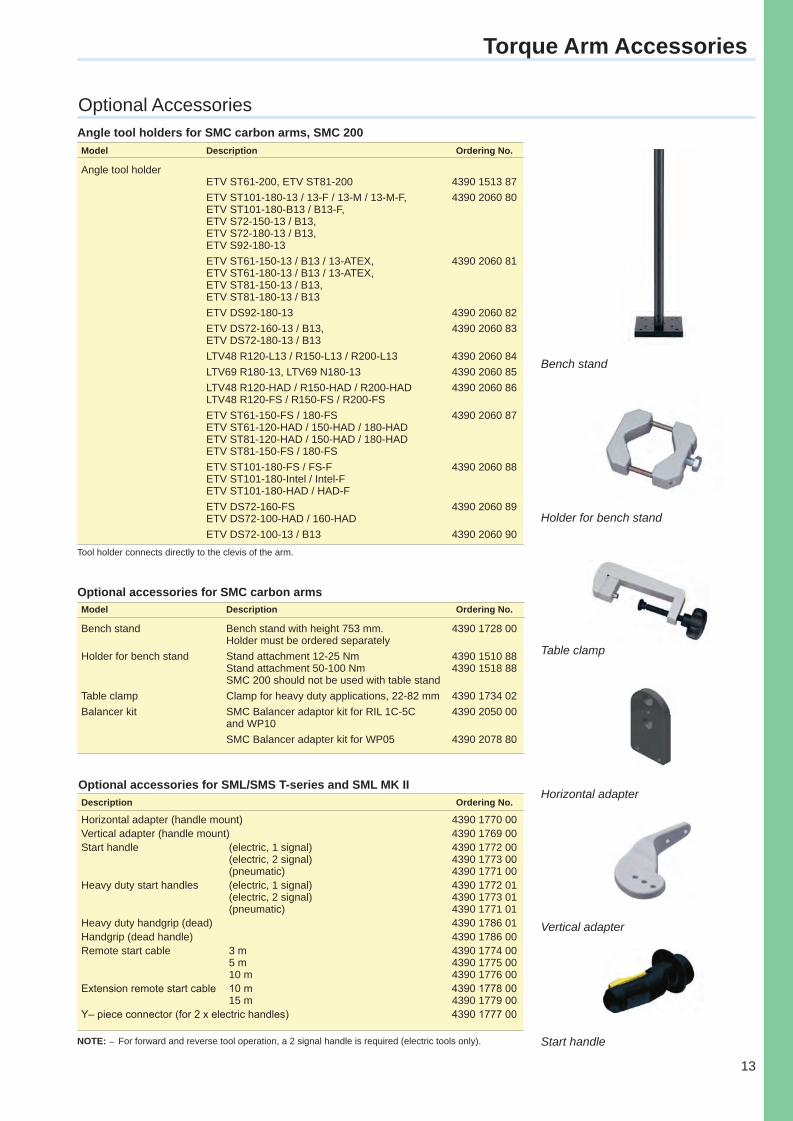
Bench stand Bench stand with height 753 mm. 4390 1728 00 Holder must be ordered separatelyHolder for bench stand Stand attachment 12-25 Nm 4390 1510 88 Stand attachment 50-100 Nm 4390 1518 88 SMC 200 should not be used with table standTable clamp Clamp for heavy duty applications, 22-82 mm 4390 1734 02Balancer kit SMC Balancer adaptor kit for RIL 1C-5C 4390 2050 00 and WP10 SMC Balancer adapter kit for WP05 4390 2078 80
Optional accessories for SMC carbon arms
Description Ordering No.
Horizontal adapter (handle mount) 4390 1770 00Vertical adapter (handle mount) 4390 1769 00Start handle (electric, 1 signal) 4390 1772 00 (electric, 2 signal) 4390 1773 00 (pneumatic) 4390 1771 00Heavy duty start handles (electric, 1 signal) 4390 1772 01 (electric, 2 signal) 4390 1773 01 (pneumatic) 4390 1771 01Heavy duty handgrip (dead) 4390 1786 01Handgrip (dead handle) 4390 1786 00Remote start cable 3 m 4390 1774 00 5 m 4390 1775 00 10 m 4390 1776 00Extension remote start cable 10 m 4390 1778 00 15 m 4390 1779 00Y– piece connector (for 2 x electric handles) 4390 1777 00
Optional accessories for SML/SMS T-series and SML MK II
NOTE: – For forward and reverse tool operation, a 2 signal handle is required (electric tools only).
Bench stand
Vertical adapter
Start handle
Horizontal adapter
Holder for bench stand
Table clamp
Torquearms-Cat-2013.indd 13 2/19/2013 10:32:18 AM
14
Torque Arm Accessories
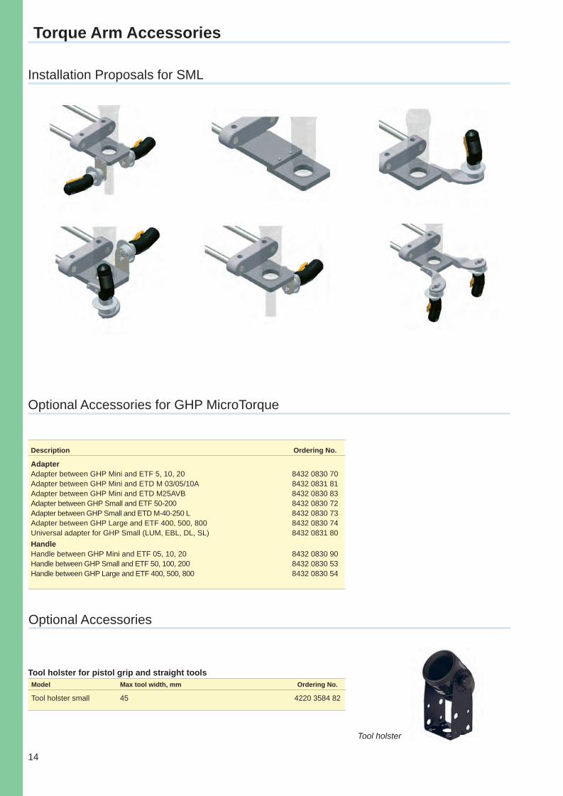
Installation Proposals for SML
Description Ordering No.
AdapterAdapter between GHP Mini and ETF 5, 10, 20 8432 0830 70Adapter between GHP Mini and ETD M 03/05/10A 8432 0831 81Adapter between GHP Mini and ETD M25AVB 8432 0830 83Adapter between GHP Small and ETF 50-200 8432 0830 72Adapter between GHP Small and ETD M-40-250 L 8432 0830 73Adapter between GHP Large and ETF 400, 500, 800 8432 0830 74Universal adapter for GHP Small (LUM, EBL, DL, SL) 8432 0831 80Handle Handle between GHP Mini and ETF 05, 10, 20 8432 0830 90Handle between GHP Small and ETF 50, 100, 200 8432 0830 53Handle between GHP Large and ETF 400, 500, 800 8432 0830 54
Optional Accessories for GHP MicroTorque
Model Max tool width, mm Ordering No.
Tool holster small 45 4220 3584 82
Optional Accessories
Tool holster for pistol grip and straight tools
Tool holster
Torquearms-Cat-2013.indd 14 2/19/2013 10:32:26 AM
15
1
2
3
5
4
Position Recognition System
Position Recognition System (PRS)
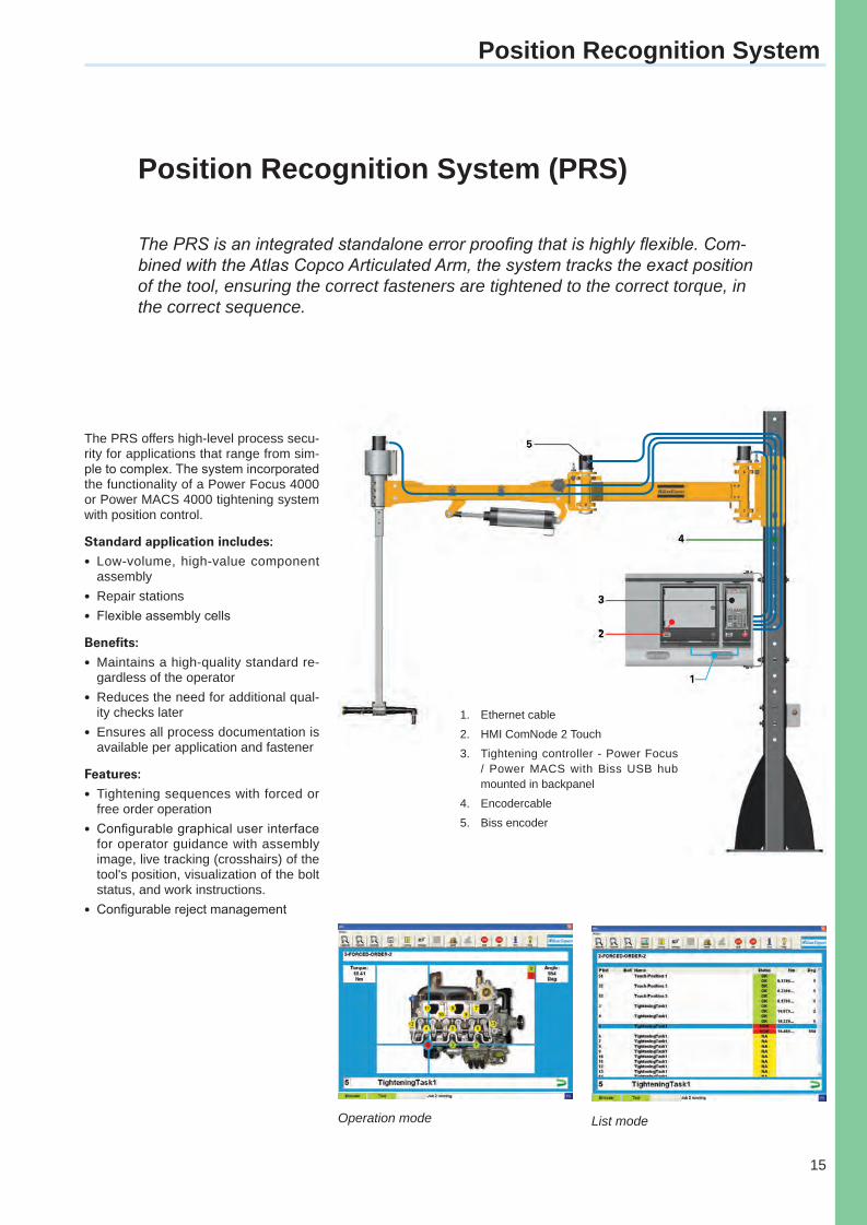
The PRS is an integrated standalone error proofing that is highly flexible. Com-bined with the Atlas Copco Articulated Arm, the system tracks the exact position of the tool, ensuring the correct fasteners are tightened to the correct torque, in the correct sequence.
The PRS offers high-level process secu-rity for applications that range from sim-ple to complex. The system incorporated the functionality of a Power Focus 4000 or Power MACS 4000 tightening system with position control.
Standard application includes:l Low-volume, high-value component
assemblyl Repair stationsl Flexible assembly cells
Benefits:l Maintains a high-quality standard re-
gardless of the operatorl Reduces the need for additional qual-
ity checks laterl Ensures all process documentation is
available per application and fastener
Features:l Tightening sequences with forced or
free order operationl Configurable graphical user interface
for operator guidance with assembly image, live tracking (crosshairs) of the tool's position, visualization of the bolt status, and work instructions.
l Configurable reject management
1. Ethernet cable
2. HMI ComNode 2 Touch
3. Tightening controller - Power Focus / Power MACS with Biss USB hub mounted in backpanel
4. Encodercable
5. Biss encoder
Operation mode List mode
Torquearms-Cat-2013.indd 15 2/19/2013 10:32:28 AM
16
Introduction – Articulated Arm
Flexible and Modular
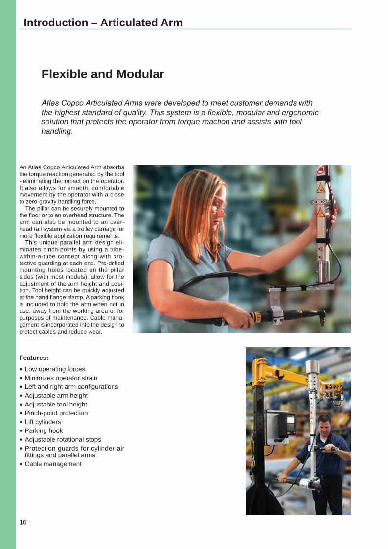
Atlas Copco Articulated Arms were developed to meet customer demands with the highest standard of quality. This system is a flexible, modular and ergonomic solution that protects the operator from torque reaction and assists with tool handling.
Features:lLow operating forceslMinimizes operator strainlLeft and right arm configurationslAdjustable arm heightlAdjustable tool heightlPinch-point protectionlLift cylinderslParking hooklAdjustable rotational stopslProtection guards for cylinder air
fittings and parallel armslCable management
An Atlas Copco Articulated Arm absorbs the torque reaction generated by the tool - eliminating the impact on the operator. It also allows for smooth, comfortable movement by the operator with a close to zero-gravity handling force.
The pillar can be securely mounted to the floor or to an overhead structure. The arm can also be mounted to an over-head rail system via a trolley carriage for more flexible application requirements.
This unique parallel arm design eli-minates pinch-points by using a tube-within-a-tube concept along with pro-tective guarding at each end. Pre-drilled mounting holes located on the pillar sides (with most models), allow for the adjustment of the arm height and posi-tion. Tool height can be quickly adjusted at the hand flange clamp. A parking hook is included to hold the arm when not in use, away from the working area or for purposes of maintenance. Cable mana-gement is incorporated into the design to protect cables and reduce wear.
Torquearms-Cat-2013.indd 16 2/19/2013 10:32:30 AM
17
Articulated Arm
NOTE: All dimensions are approximate. Arm 4000/6000 also available, upon request, with the following pillar heights: 3.65 m (12 ft) or 4.250 m (14 ft). Minimum required line pressure: 4 bar (60 psi) for Arm 250 and 6.2 bar (90 psi) for Arm 500/1000/2000/4000/6000.
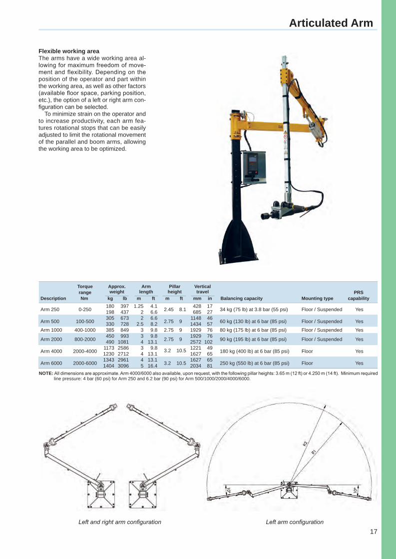
Flexible working areaThe arms have a wide working area al-lowing for maximum freedom of move-ment and flexibility. Depending on the position of the operator and part within the working area, as well as other factors (available fl oor space, parking position, etc.), the option of a left or right arm con-fi guration can be selected.
To minimize strain on the operator and to increase productivity, each arm fea-tures rotational stops that can be easily adjusted to limit the rotational movement of the parallel and boom arms, allowing the working area to be optimized.
Torque Approx. Arm Pillar Vertical range weight length height travel PRSDescription Nm kg lb m ft m ft mm in Balancing capacity Mounting type capability
Arm 250 0-250 180 397 1.25 4.1
2.45 8.1 428 17
34 kg (75 lb) at 3.8 bar (55 psi) Floor / Suspended Yes 198 437 2 6.6 685 27
Arm 500 100-500 305 673 2 6.6
2.75 9 1148 46
60 kg (130 lb) at 6 bar (85 psi) Floor / Suspended Yes 330 728 2.5 8.2 1434 57 Arm 1000 400-1000 385 849 3 9.8 2.75 9 1929 76 80 kg (175 lb) at 6 bar (85 psi) Floor / Suspended Yes
Arm 2000 800-2000 450 993 3 9.8
2.75 9 1929 76
90 kg (195 lb) at 6 bar (85 psi) Floor / Suspended Yes 490 1081 4 13.1 2572 102
Arm 4000 2000-4000 1173 2586 3 9.8 3.2 10.5 1221 49
180 kg (400 lb) at 6 bar (85 psi) Floor Yes 1230 2712 4 13.1 1627 65
Arm 6000 2000-6000 1343 2961 4 13.1
3.2 10.5 1627 65
250 kg (550 lb) at 6 bar (85 psi) Floor Yes 1404 3096 5 16.4 2034 81
Left and right arm confi guration Left arm confi guration
Torquearms-Cat-2013.indd 17 2/19/2013 10:32:34 AM
18
Accessories Articulated Arm
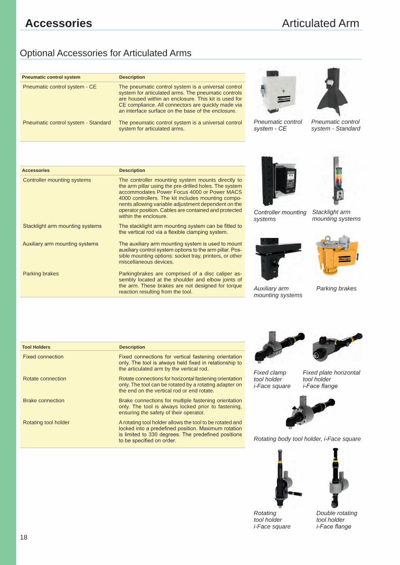
Pneumatic control system Description
Pneumatic control system - CE The pneumatic control system is a universal control system for articulated arms. The pneumatic controls are housed within an enclosure. This kit is used for CE compliance. All connectors are quickly made via an interface surface on the base of the enclosure.
Pneumatic control system - Standard The pneumatic control system is a universal control system for articulated arms.
Accessories Description
Controller mounting systems The controller mounting system mounts directly to the arm pillar using the pre-drilled holes. The system accommodates Power Focus 4000 or Power MACS 4000 controllers. The kit includes mounting compo-nents allowing variable adjustment dependent on the operator position. Cables are contained and protected within the enclosure.
Stacklight arm mounting systems The stacklight arm mounting system can be fitted to the vertical rod via a flexible clamping system.
Auxiliary arm mounting systems The auxiliary arm mounting system is used to mount auxiliary control system options to the arm pillar. Pos-sible mounting options: socket tray, printers, or other miscellaneous devices.
Parking brakes Parkingbrakes are comprised of a disc caliper as-sembly located at the shoulder and elbow joints of the arm. These brakes are not designed for torque reaction resulting from the tool.
Tool Holders Description
Fixed connection Fixed connections for vertical fastening orientation only. The tool is always held fixed in relationship to the articulated arm by the vertical rod.
Rotate connection Rotate connections for horizontal fastening orientation only. The tool can be rotated by a rotating adapter on the end on the vertical rod or end rotate.
Brake connection Brake connections for multiple fastening orientation only. The tool is always locked prior to fastening, ensuring the safety of their operator.
Rotating tool holder A rotating tool holder allows the tool to be rotated and locked into a predefined position. Maximum rotation is limited to 330 degrees. The predefined positions to be specified on order.
Pneumatic control system - CE
Pneumatic control system - Standard
Controller mounting systems
Auxiliary arm mounting systems
Parking brakes
Stacklight arm mounting systems
Fixed clamptool holderi-Face square
Rotating tool holderi-Face square
Fixed plate horizontal tool holderi-Face flange
Double rotating tool holderi-Face flange
Rotating body tool holder, i-Face square
Optional Accessories for Articulated Arms
Torquearms-Cat-2013.indd 18 2/19/2013 10:32:37 AM
19
A
C
B
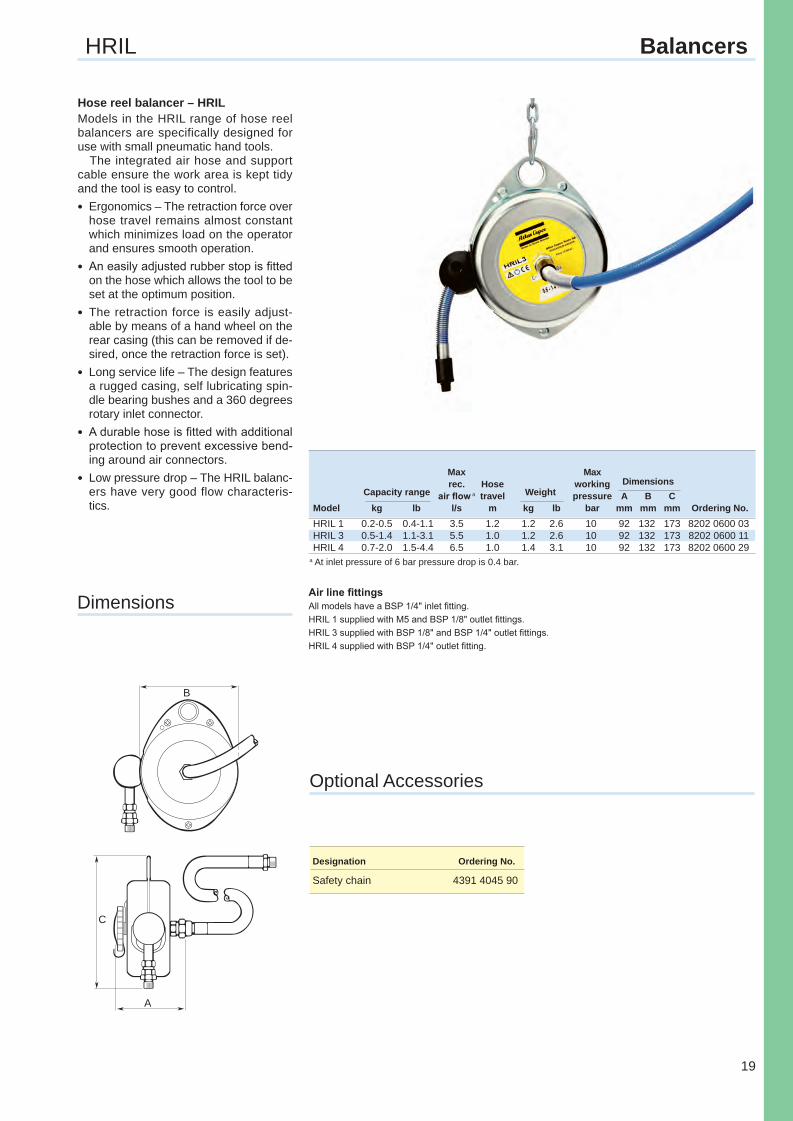
Hose reel balancer – HRILModels in the HRIL range of hose reel balancers are specifically designed for use with small pneumatic hand tools.
The integrated air hose and support cable ensure the work area is kept tidy and the tool is easy to control.lErgonomics – The retraction force over
hose travel remains almost constant which minimizes load on the operator and ensures smooth operation.
lAn easily adjusted rubber stop is fi tted on the hose which allows the tool to be set at the optimum position.
lThe retraction force is easily adjust-able by means of a hand wheel on the rear casing (this can be removed if de-sired, once the retraction force is set).
lLong service life – The design features a rugged casing, self lubricating spin-dle bearing bushes and a 360 degrees rotary inlet connector.
lA durable hose is fi tted with additional protection to prevent excessive bend-ing around air connectors.
lLow pressure drop – The HRIL balanc-ers have very good flow characteris-tics.
Air line fi ttingsAll models have a BSP 1/4" inlet fi tting.HRIL 1 supplied with M5 and BSP 1/8" outlet fi ttings.HRIL 3 supplied with BSP 1/8" and BSP 1/4" outlet fi ttings.HRIL 4 supplied with BSP 1/4" outlet fi tting.
Designation Ordering No.
Safety chain 4391 4045 90
a At inlet pressure of 6 bar pressure drop is 0.4 bar.
HRIL Balancers
Dimensions
Optional Accessories
Max Max rec. Hose working Dimensions Capacity range air fl ow a travel Weight pressure A B CModel kg lb l/s m kg lb bar mm mm mm Ordering No.HRIL 1 0.2-0.5 0.4-1.1 3.5 1.2 1.2 2.6 10 92 132 173 8202 0600 03HRIL 3 0.5-1.4 1.1-3.1 5.5 1.0 1.2 2.6 10 92 132 173 8202 0600 11HRIL 4 0.7-2.0 1.5-4.4 6.5 1.0 1.4 3.1 10 92 132 173 8202 0600 29
Torquearms-Cat-2013.indd 19 2/19/2013 10:32:38 AM
20
A B
C
Cable Di men sions Capacity range length Weight A B CModel kg lb m kg lb mm mm mm Ordering No.RetractorsRIL 1C 0.0-0.5 0.0-1.7 1.5 0.6 1.3 51 106 238 8202 0700 02RIL 2C 0.4-1.0 0.9-2.2 1.5 0.6 1.3 51 106 238 8202 0701 19RIL 4C 1.0-2.0 2.2-4.4 1.5 0.6 1.3 51 106 238 8202 0702 18RIL 5C 1.4-2.3 3.1-5.1 1.5 0.6 1.3 51 106 238 8202 0703 25RIL 5 0.4-2.3 0.9-5.1 2.4 2.0 4.4 70 157 308 8202 0703 09RIL 5LR b 0.4-2.3 0.9-5.1 2.4 2.0 4.4 70 157 308 8202 0703 15RIL 10C 2.0-5.0 4.4-11.0 2.4 2.7 6.0 84 190 369 8202 0704 16RIL 10CS a 2.0-5.0 4.4-11.0 2.4 2.7 6.0 84 190 369 8202 0704 20RIL 15C 5.0-7.0 11.0-15.4 2.4 3.2 7.1 84 190 369 8202 0705 15RIL 15CS a 5.0-7.0 11.0-15.4 2.4 3.2 7.1 84 190 369 8202 0705 20RIL 22C 6.0-10.0 13.2-22.0 2.4 3.2 7.1 84 190 369 8202 0706 14RIL 22CS a 6.0-10.0 13.2-22.0 2.4 3.2 7.1 84 190 369 8202 0706 20
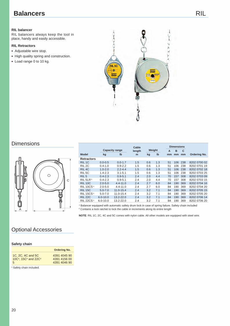
RIL balancerRIL balancers always keep the tool in place, handy and easily accessible.
RIL RetractorslAdjustable wire stop.lHigh quality spring and construction.lLoad range 0 to 10 kg.
Safety chain Ordering No.
1C, 2C, 4C and 5C 4391 4045 9010Ca, 15Ca and 22Ca 4391 4156 005 4391 4046 90
Balancers RIL
Dimensions
a Balancer equipped with automatic safety drum lock in case of spring failure. Safety chain includedb Contains a lock ratchet to lock the cable in increments along its entire length
NOTE: RIL 1C, 2C, 4C and 5C comes with nylon cable. All other models are equipped with steel wire.
a Safety chain included.
Optional Accessories
Torquearms-Cat-2013.indd 20 2/19/2013 10:32:39 AM
21
B A
C
Cable Di men sions Capacity range length Weight A B CModel kg lb m kg lb mm mm mm Ordering No.COL 1 01 0.7-1.3 1.5-2.9 1.7 0.5 1.1 108 72 245 8202 0750 01COL 1 02 1.0-2.0 2.2-4.4 1.7 0.5 1.1 108 72 245 8202 0750 19COL 2 03 1.7-3.5 3.7-7.7 2.4 2.3 5.1 155 116 427 8202 0750 27COL 2 04 3.0-6.0 6.6-13.2 2.4 2.3 5.1 155 116 427 8202 0750 35COL 2 05 4.7-7.0 10.4-15.4 2.4 2.5 5.5 155 116 427 8202 0750 43COL 3 07 5.5-9.0 12.1-19.8 2.4 3.3 7.3 196 116 427 8202 0750 50COL 3 10 8.0-13.0 17.6-28.7 2.4 3.4 7.5 196 116 427 8202 0750 68COL 3 15 12.5-17.0 27.6-37.5 2.4 3.8 8.4 196 116 427 8202 0750 76COL 4 18 14.0-22.0 30.9-48.5 2.4 13.2 29.1 244 193 620 8202 0774 11COL 4 22 17.0-28.0 37.4-61.7 2.4 13.9 30.6 244 193 620 8202 0750 84COL 4 30 24.0-38.0 52.9-83.8 2.4 14.5 32.0 244 193 620 8202 0750 92COL 4 42 36.0-49.0 79.4-107.8 2.4 14.9 32.8 244 193 620 8202 0751 00COL 4 50 43.0-55.0 98.4-121.3 2.4 15.3 33.7 244 193 620 8202 0751 18Safety brakeCOL 2 03S 1.7-3.5 3.7-7.7 2.4 2.3 5.1 155 116 427 8202 0775 93COL 2 04S 3.0-6.0 6.6-13.2 2.4 2.3 5.1 155 116 427 8202 0776 01COL 2 05S 4.7-7.0 10.4-15.4 2.4 2.5 5.3 155 116 427 8202 0776 19COL 3 07S 5.5-9.0 12.1-19.8 2.4 3.3 7.3 196 116 427 8202 0776 27COL 3 10S 8.0-13.0 17.6-28.7 2.4 3.4 7.5 196 116 427 8202 0776 35COL 3 15S 12.5-17.0 27.6-37.5 2.4 3.8 8.4 196 116 427 8202 0776 43
COLIBRI Balancers
Dimensions
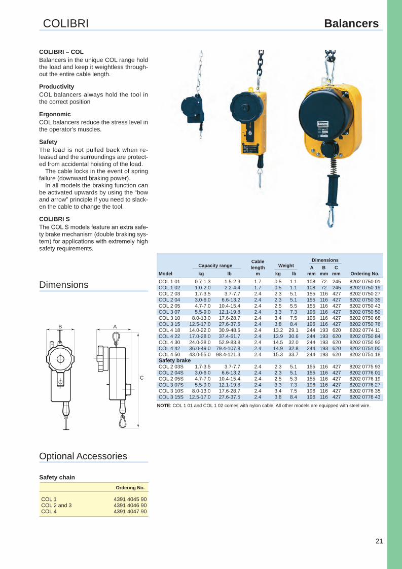
COLIBRI – COLBalancers in the unique COL range hold the load and keep it weightless through-out the entire cable length.
ProductivityCOL balancers always hold the tool in the correct position
ErgonomicCOL balancers reduce the stress level in the operator's muscles.
SafetyThe load is not pulled back when re-leased and the surroundings are protect-ed from accidental hoisting of the load.
The cable locks in the event of spring failure (downward braking power).
In all models the braking function can be activated upwards by using the “bow and arrow” principle if you need to slack-en the cable to change the tool.
COLIBRI SThe COL S models feature an extra safe-ty brake mechanism (double braking sys-tem) for applications with extremely high safety requirements.
Optional Accessories
Safety chain Ordering No.
COL 1 4391 4045 90COL 2 and 3 4391 4046 90COL 4 4391 4047 90
NOTE: COL 1 01 and COL 1 02 comes with nylon cable. All other models are equipped with steel wire.
Torquearms-Cat-2013.indd 21 2/19/2013 10:32:41 AM
22
B
A
C
Cable Di men sion
Capacity range length Weight A B CModel kg lb m kg lb mm mm mm Ordering No.WP 05-1 0.4-1.2 0.9-2.6 1.6 1.3 2.9 71 141 460 8202 0778 00WP 05-3 1.2-2.6 2.6-5.7 1.6 1.4 3.1 71 141 460 8202 0778 01WP 05-4 2.6-3.8 5.7-8.4 1.6 1.5 3.3 71 141 460 8202 0778 02WP 05-5 3.8-5.2 8.4-11.5 1.6 1.5 3.3 71 141 460 8202 0778 03WP 05-6 5.2-6.5 11.5-14.3 1.6 1.5 3.3 71 141 460 8202 0778 04WP 10-3 3-5 6.6-11 2 2.9 6.4 130 188 521 8202 0779 00WP 10-4.5 4.5-7 10-15.4 2 3.1 6.8 130 188 521 8202 0779 01WP 10-6 6-10 13-22 2 3.2 7.0 130 188 521 8202 0779 02WP 10-9 9-14 20-31 2 3.4 7.5 130 188 521 8202 0779 03WP 10-13 13-17 29-37 2 3.6 8.0 130 188 521 8202 0779 04WP 10-16 16-21 35-46 2 3.8 8.4 130 188 521 8202 0779 05WP 20-15 15-25 33-55 2 7.8 17.2 152 218 521 8202 0780 00WP 20-25 25-35 55-77 2 8.9 19.6 152 218 521 8202 0780 01WP 20-35 35-45 77-99 2 9.5 21.0 152 218 521 8202 0780 02WP 20-45 45-55 99-121 2 9.8 21.5 152 218 521 8202 0780 03WP 30-12 12-20 26-44 2 14.8 32.6 203 285 749 8202 0781 00WP 30-20 20-30 44-66 2 15.2 33.5 203 285 749 8202 0781 01WP 30-30 30-45 66-99 2 16.9 37.3 203 285 749 8202 0781 02WP 30-45 45-60 99-132 2 17.3 38.1 203 285 749 8202 0781 03WP 30-60 60-75 132-165 2 18.7 41.2 203 285 749 8202 0781 04WP 30-75 75-90 165-198 2 19.7 43.4 203 285 749 8202 0781 05WP 30-90 90-100 198-220 2 19.9 43.4 203 285 749 8202 0781 06WP 40-100 100-115 220-254 3 42.0 43.9 348 320 800 8202 0782 00WP 40-115 115-130 254-287 3 44.0 97.0 348 320 800 8202 0782 01WP 40-130 130-140 287-309 3 46.0 101 348 320 800 8202 0782 02WP 40-140 140-150 309-331 3 48.0 106 348 320 800 8202 0782 03
Balancers WP
Dimensions
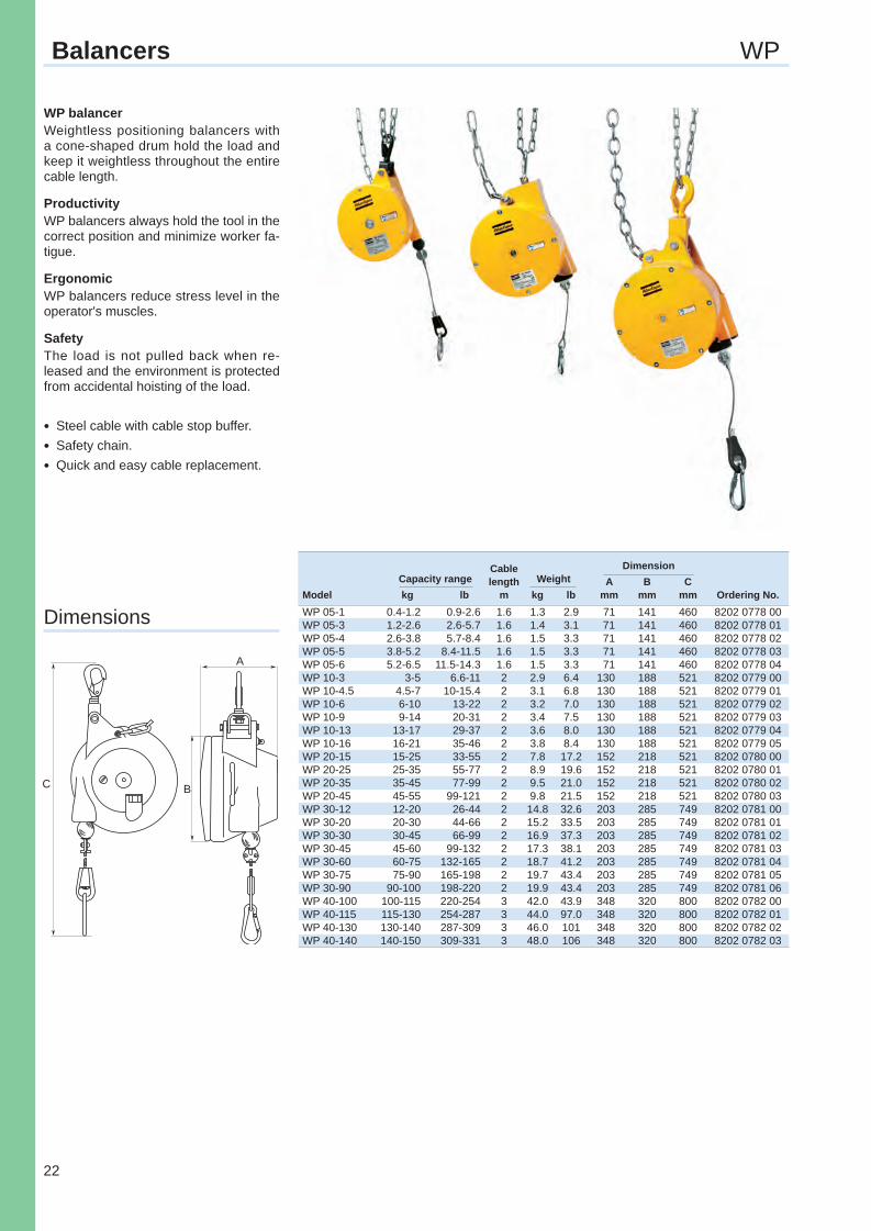
WP balancerWeightless positioning balancers with a cone-shaped drum hold the load and keep it weightless throughout the entire cable length.
ProductivityWP balancers always hold the tool in the correct position and minimize worker fa-tigue.
ErgonomicWP balancers reduce stress level in the operator's muscles.
SafetyThe load is not pulled back when re-leased and the environment is protected from accidental hoisting of the load.
lSteel cable with cable stop buffer.lSafety chain.lQuick and easy cable replacement.
Torquearms-Cat-2013.indd 22 2/19/2013 10:32:44 AM

23
Notes
Torquearms-Cat-2013.indd 23 2/19/2013 10:32:44 AM

24
Notes
Torquearms-Cat-2013.indd 24 2/19/2013 10:32:44 AM

www.atlascopco.com
9833
197
2 01
Rec
ycla
ble
pap
er. P
rin
ted
in S
wed
en 2
013:
1
Namnlöst-1 4 2/19/2013 10:46:26 AM