Embed Size (px)
Citation preview
ATM COMPONENTSATM COMPONENTSATM COMPONENTSATM COMPONENTSPresented by:Presented by:
ANG BEE KEEANG BEE KEE WET 020005WET 020005CHONG SIT MEICHONG SIT MEI WET 020024WET 020024LAI YIN LENGLAI YIN LENG WET 020056WET 020056LEE SEANG LEILEE SEANG LEI WET 020060WET 020060
Table of Contents• ATM Networks
– Presented by Chong Sit Mei
• Virtual Path (VP) Switch– Presented by Ang Bee Kee
• Virtual Path Connection (VPC) Switch– Presented by Lai Yin Leng
• ATM Switching Techniques– Presented by Lee Seang Lei

ATM COMPONENTS
•ATM contains two basic components: an endstation, a
computer connected to the ATM network; and an ATM switch,
the device responsible for connecting endstations and making
sure data is transferred successfully.
•ATM is connection-oriented.
•establishes a defined path known as a virtual circuit (VC)
ATM Networks
• sends a series of same-size frames called cells along the
virtual circuit towards the destination.
• the ATM endpoint also negotiates a Quality of Service (QoS)
contract for the virtual circuit.
• it spells out the bandwidth, maximum transit delay,
acceptable variance in the transit delay, etc, that the VC
provides, and this contract extends from one endpoint to
the other through all of the intermediate ATM switches.
• ATM traffic is established at the outset, and the switching
hardware merely needs to examine a simple header to
identify the proper path.
• ATM allows a location to establish a full duplex connection
with multiple locations at the same time.
• To travel across the ATM network, data is segmented into
same-size cells, and encapsulated with a header that
contains switching, congestion, and error-checking
information.
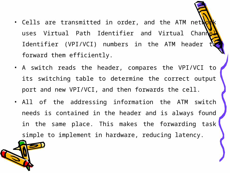
• Cells are transmitted in order, and the ATM network uses
Virtual Path Identifier and Virtual Channel Identifier
(VPI/VCI) numbers in the ATM header to forward them
efficiently.
• A switch reads the header, compares the VPI/VCI to its
switching table to determine the correct output port and
new VPI/VCI, and then forwards the cell.
• All of the addressing information the ATM switch needs is
contained in the header and is always found in the same
place. This makes the forwarding task simple to implement
in hardware, reducing latency.
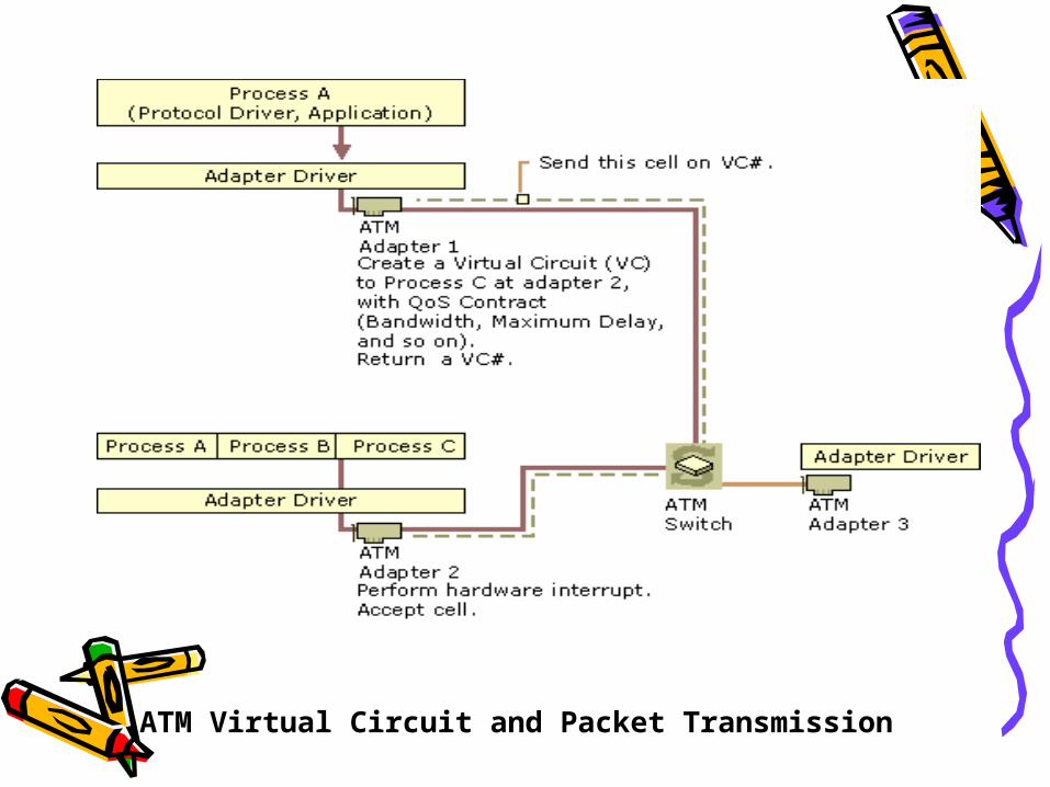
ATM Virtual Circuit and Packet Transmission
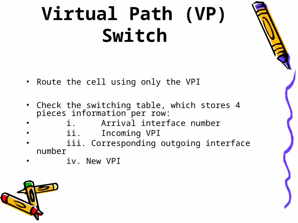
Virtual Path (VP) Switch
• Route the cell using only the VPI
• Check the switching table, which stores 4 pieces information per row:
• i. Arrival interface number• ii. Incoming VPI• iii. Corresponding outgoing interface number• iv. New VPI
VP Switch (cont.)
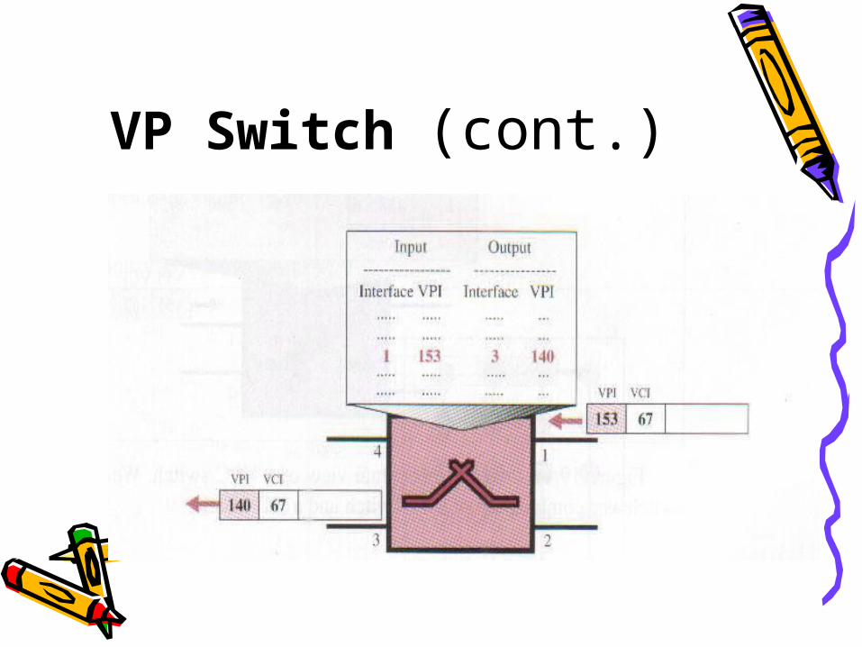
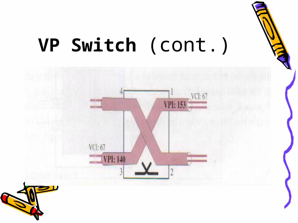
VP Switch (cont.)• The figure shows how a VP switch routes the cell.
• A cell with VPI of 153 arrives at switch interface 1.
• The switch checks its switching table, finds the entry with interface 1 and VPI 153 and discover that the combination corresponds to output interface 3 with VPI 140.
• It changes the VPI in the header to 140 and sends the cell out through interface 3.
VP Switch (cont.)
Virtual Path Connection (VPC)
Switch• Virtual Path Connection (VPC) means a group of logical connections
between one ATM switch port and another ATM switch port.
• VPC are provided for the purpose of user-user, user-network, network-network information transfer.
• Can be established between :-end users-network entities-end user and network entity
• VPC is established at the time a VC (virtual circuit) session is activated.
VPC Switch (cont.)
• VPC switch routes the cell using both the VPIs (Virtual Path Identifier) and VCIs (Virtual Circuits Identifier).
• The routing requires the whole identifier.
• It can assigned within the Virtual Path (VPs).
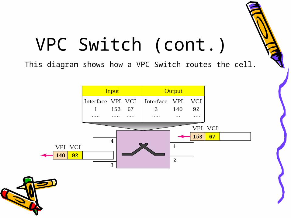
VPC Switch (cont.)This diagram shows how a VPC Switch routes the cell.
VPC Switch (cont.)• Routing with a VPC switch.
– A cell with a VPI of 153 and VCI of 67 arrives at switch interface 1.
– The switch checks its switching table, which stores six pieces of information per row.
– The switch finds the entry with the interface 1, VPI 153, and VCI 67 and discovers that the combination corresponds to output interface 3, VPI 140, and VCI 192.
– It changes the VPI and VCI in the header to 140 and 92.
– Respectively, sends the cell out through interface 3.
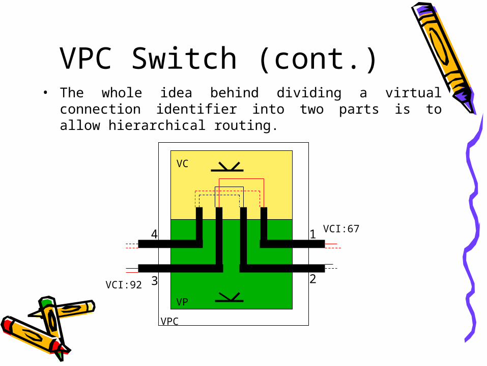
VPC Switch (cont.)• The whole idea behind dividing a virtual connection
identifier into two parts is to allow hierarchical routing.
1
23
4
VC
VP
VPC
VCI:92
VCI:67
Advantages
• Simplified network architecture. Network transport functions can be separated into those related to an individual logical connection (virtual channel) and those related to a group of logical connections (virtual path).
• Increased network performance and reliability. The network deals with aggregated (and therefore fewer) entities.
Advantages (cont.)• Reduced processing and short connection setup time.
Much of the work is done when the virtual path is set up. The addition of new virtual channels to an existing virtual path involves minimal processing.
• Enhanced network services. The virtual path is used internal to the network but is also visible to the end user. Thus, the user may define closed user groups or closed networks of virtual-channel bundles.
ATM Switching Techniques
• Within an ATM switch, the cell switch fabric plays a very key role.
• Its main responsibility is to relay ATM cells as quickly as possible.
• The cell switch fabric accomplishes this by performing 2 major functions:
• -Concentration, expansion, multiplexing/demultiplexing of traffic.
• -Routing and buffering of traffic.
ATM Switching Techniques
• Shared Memory Switch• Shared Bus Switch• Crossbar Switch• Multistage Switching• Banyan/Delta Switching
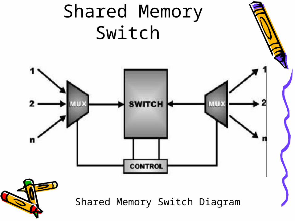
Shared Memory Switch• The Shared Memory Switch is a technique that uses a
common memory for the storage of cells and switching fabric.
• Incoming cells are multiplexed onto a single line to the switch and are placed in queues.
• Then, based on cell headers information and internal tags, the switching function decides the order in which cells are move from the input queues to the output queues and ultimately onto the output ports.
Shared Memory Switch
Shared Memory Switch Diagram

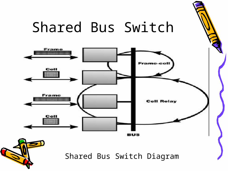
• The Shared Bus Switch approach utilizes a bus or dual bus architecture to switch cell traffic.
• Cell traffic is carried through the bus for transmission. With this technique, frame based traffic can also be supported since the busses operates in cell mode.
• Therefore, the traffic is diced into 48-octet pieces with 5-byte header attached for transmission onto the bus.
• It is easy to see that frame based traffic can be converted to ATM cells and vice versa with this approach.
Shared Bus Switch
Shared Bus Switch
Shared Bus Switch Diagram
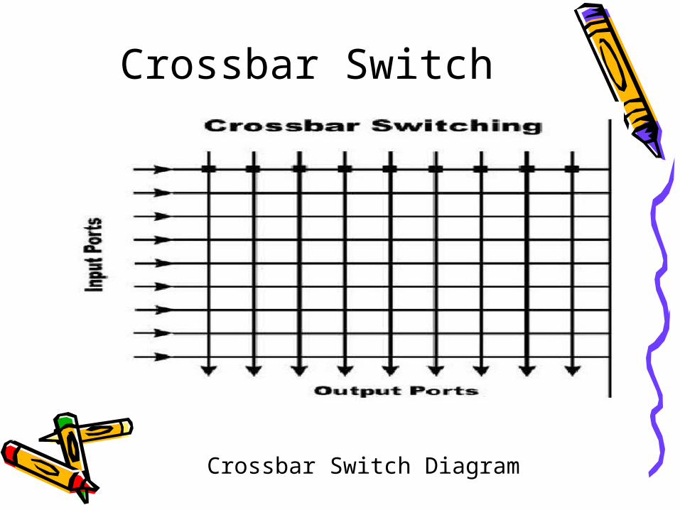
Crossbar Switch• The Crossbar Switch is a simple matrix-like space
division technique that physically interconnects any of the N inputs to any of the N outputs at crosspoints.
• Therefore, a crossbar switching fabric consists of N2 crosspoints.
Crossbar Switch
Crossbar Switch Diagram
Multistage Switching
• The Multistage Switching uses a similar concept to the crossbar switch technique.
• However, it is designed with a more tree-like structure to reduce the N squared crosspoints requirement yielding a more economical arrangement.
• Basically, the inputs and output lines are divided into subgroups of N inputs and N outputs.
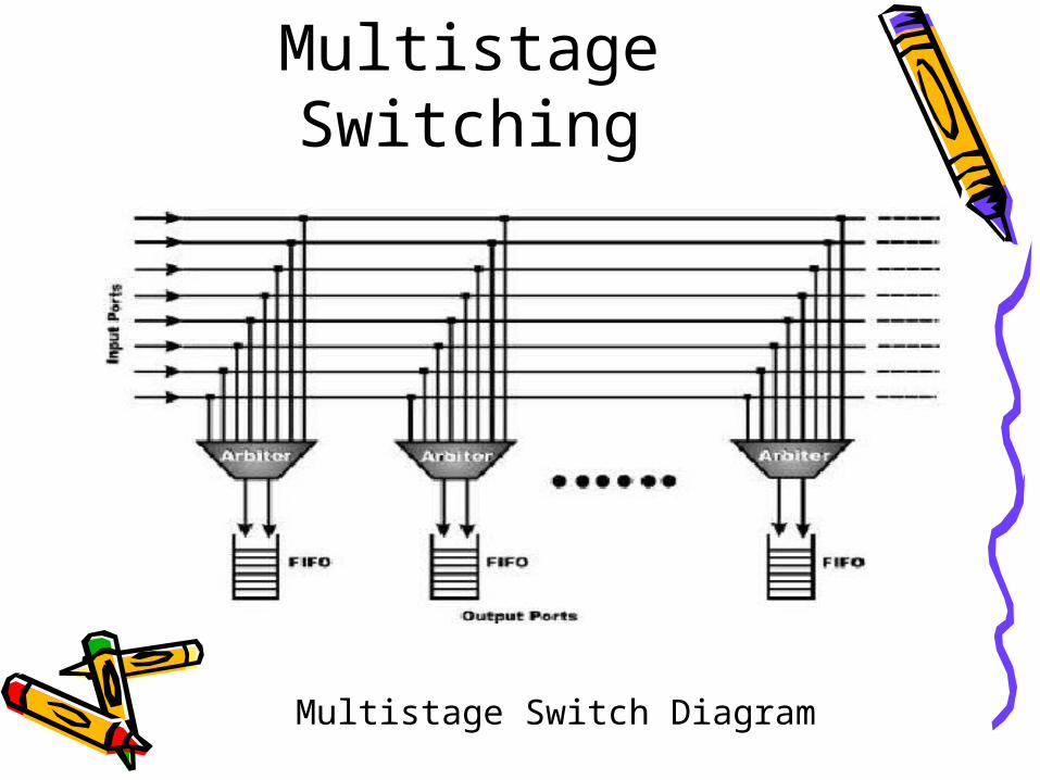
Multistage Switching
Multistage Switch Diagram
Banyan/Delta Switching• The Banyan/Delta Switching is a concept of an
interconnection of stages of switching elements.
• This technique allows only one path of connection existing between an input to the final output port.
• With this approach, the routing of traffic is quite simple and straightforward.
• However, it has one major drawback in that cells may be blocked if more than one arrives at a switching element at the same time.

Banyan/Delta Switching
Banyan/Delta Switch Diagram

The End