Embed Size (px)
Citation preview
US Ecology Idaho, Inc. EPA ID. No.: IDD073114654
Effective Date: July 28, 2016 Modification Date: November 18, 2017
Attachment 17 1
Attachment 17 Surface Impoundments
Table of Contents
D.4 Surface Impoundments........................................................................................................................ 4
D.4.a List of Acceptable Wastes ................................................................................................................... 6
D.4.b. Exemption Requests .......................................................................................................................... 6 D.4.b.(1) Liner System Description ........................................................................................................... 6
D.4.b.(1)(a) Collection Pond #’s 1 and 3 ............................................................................................ 6 D.4.b.(1)(b) The Evaporation Pond ................................................................................................. 7
D.4.b.(2) Liner System Location Relative to High Water Table................................................................. 7 D.4.b.(3) Loads on Liner System ............................................................................................................... 8
D.4.b.(3)(a) Pressure Gradients ......................................................................................................... 8 D.4.b.(3)(b) Installation Stresses........................................................................................................ 8 D.4.b.(3)(c) Operational Stresses ...................................................................................................... 8
D.4.b.(4) Liner System Coverage .............................................................................................................. 8 D.4.b.(5) Liner System Exposure Prevention ............................................................................................ 8
D.4.c Liner System - Foundation .................................................................................................................. 8 D.4.c.(1) Foundation Description ............................................................................................................... 9 D.4.c.(2) Subsurface Exploration Data ...................................................................................................... 9 D.4.c.(3) Laboratory Subsurface Testing Data .......................................................................................... 9 D.4.c.(4) Engineering Analyses ................................................................................................................. 9
D.4.d Liner Systems – Liners ........................................................................................................................ 9 D.4.d.(1) Synthetic Liners .......................................................................................................................... 9
D.4.d.(1)(a) Synthetic Liner Compatibility Data .................................................................................. 9 D.4.d.(1)(b) Synthetic Liner Strength ............................................................................................... 10 D.4.d.(1)(c) Synthetic Liner Bedding ................................................................................................ 10
D.4.d.(2) Soil Liners ................................................................................................................................. 11
D.4.e Liner System-Leachate Detection System ........................................................................................ 11 D.4.e.(1) LDCRSs .................................................................................................................................... 11
D.4.e.(1)(a) Collection Pond #’s 1 and 3 and Original Evaporation Pond ....................................... 11 D.4.e.(1)(b) Reconstructed Evaporation Pond ................................................................................. 12 The LDCRS for the reconstructed Evaporation Pond is described in detail in Appendix D.4.11. ... 12
D.4.f Liner System - Construction and Maintenance .................................................................................. 12 D.4.f.(1) Material Specifications .............................................................................................................. 12
D.4.f.(1)(a) Synthetic Liners ............................................................................................................. 12 D.4.f.(1)(b) Soil Liners ...................................................................................................................... 12 D.4.f.(1)(c) Leachate Detection System ........................................................................................... 12
D.4.f.(2) Construction Specifications ....................................................................................................... 13 D.4.f.(3) Construction Quality Control Program ...................................................................................... 13 D.4.f.(4) Maintenance Procedures for the Leachate Detection System .................................................. 13 D.4.f.(5) Liner Repairs During Operation................................................................................................. 13
D.4.g Prevention of Overtopping ................................................................................................................. 15
D.4.h Dike Stability ................................................................................................................................ 15
US Ecology Idaho, Inc. EPA ID. No.: IDD073114654
Effective Date: July 28, 2016 Modification Date: November 18, 2017
Attachment 17 2
D.4.h.(1) Engineer’s Certification ............................................................................................................ 15 D.4.h.(2) Dike Design Description ........................................................................................................... 16 D.4.h.(3) Erosion and Piping Protection .................................................................................................. 16 D.4.h.(4) Subsurface Soil Conditions ...................................................................................................... 16 D.4.h.(5) Stability Analysis ...................................................................................................................... 16 D.4.h.(6) Strength and Compressibility Results ...................................................................................... 16 D.4.h.(7) Dike Construction Procedures .................................................................................................. 17 D.4.h.(8) Dike Construction Inspection Program ..................................................................................... 17
D.4.i Action Leakage Rate .......................................................................................................................... 17
D.4.j Response Actions ............................................................................................................................... 17
D.4.k Monitoring and Inspection ................................................................................................................. 17
D.4.l Emergency Repairs; Contingency Plans ............................................................................................ 18
D.4.m Closure and Post-Closure Care ....................................................................................................... 18
D.4.n Special Requirements for Ignitable or Reactive Waste ..................................................................... 18
D.4.o Special Requirements for Incompatible Wastes ............................................................................... 18
D.4.p Air Emission Standards ..................................................................................................................... 18
US Ecology Idaho, Inc. EPA ID. No.: IDD073114654
Effective Date: July 28, 2016
Attachment 17 3
List of Figures Figure D-8 Certification of Liner System Repair Form
Figure D-9 Liner System Repair Report
List of Appendices Appendix D.4.11 Evaporation Pond Reconstruction Engineering Report
US Ecology Idaho, Inc. EPA ID. No.: IDD073114654
Effective Date: July 28, 2016 Modification Date: November 18, 2017
Attachment 17 4
D.4 Surface Impoundments
This Section provides information for the following RCRA surface impoundment units located at the facility:
The Evaporation Pond;
Collection Pond #1; and
Collection Pond #3. These surface impoundments are located as shown on the Facility Site Plan, Figure D-1. The Evaporation Pond is the primary surface impoundment at the facility and is used to evaporate treated leachate and on-site and off-site generated liquids. The Evaporation Pond was originally constructed in 1984 and all information contained in this section refers to the original construction. A reconstruction plan has been adopted and is included for future development. The reconstruction plan and all associated performance criteria are located in Appendix D.4.11. The primary purpose of Collection Ponds #1 and #3 is the collection and containment of surface run-off from within the facility, however, the Ponds can also store leachate and other liquids in accordance with the general requirements and limitations found in the WAP for liquid wastes placed into Surface Impoundments. In addition, the facility does not manage any wastes subject to the requirements of 40 CFR Part 264, Subpart CC in surface impoundments, therefore these regulations do not apply. Run-off, leachate, and aqueous wastes either flow to the surface impoundments by gravity or are transferred by pumps, tank trucks, vacuum trucks, or by other appropriate means. The stored aqueous wastes are treated by solar evaporation. If residues in the surface impoundments reach a level of 1 foot or greater, they will be carefully removed to avoid damage to the liner system. The residual sediments are analyzed for proper disposal as necessary. Site run-off collected in the Collection Ponds may also be utilized for process water. The Collection Ponds collect surface run-off from active areas and were designed to retain the run-off from a 25-year, 24-hour storm (1¾ in.) while maintaining 2.8 ft. of freeboard. General specifications for the surface impoundments, including excavation, liner placement, flow zone materials, berm construction, roadway construction, drainage control construction, etc., are provided in Appendix D.4.1. Any needed repairs are observed and certified by a licensed Professional Engineer (PE) prior to returning the surface impoundment to service, in accordance with 40 CFR §264.227(d). An example certification is included as Figure D-8. A liquid waste recirculation system may be constructed in the Evaporation Pond to enhance evaporation of liquids and prevent stagnation of the water. This system would consist of a recirculation pump or pumps, piping, and a perforated distribution pipe that would be installed along the Evaporation Pond’s side slopes below the top of the slope. The liquids would be discharged through the distribution pipe and flow over the HDPE liner down to the liquid surface in the Evaporation Pond. The system would be designed such that “misting” of liquids and the airborne migration of mist beyond the boundaries of the surface impoundment will not occur. The details of the systems design will be submitted to IDEQ for approval. The design storage volume capacity of all surface impoundments (i.e. Collection Ponds No. 1 and 3) and the Evaporation Pond, were re-evaluated in the previous revision to the SWMP based on a total storage volume of a 100-year, 24-hour storm, plus freeboard. The design freeboard depth was based on maximum wave height calculations for on-site surface impoundments using a maximum wind velocity of 70 miles per hour (i.e. worst case scenario). Based on existing site conditions, the computed
US Ecology Idaho, Inc. EPA ID. No.: IDD073114654
Effective Date: July 28, 2016 Modification Date: November 18, 2017
Attachment 17 5
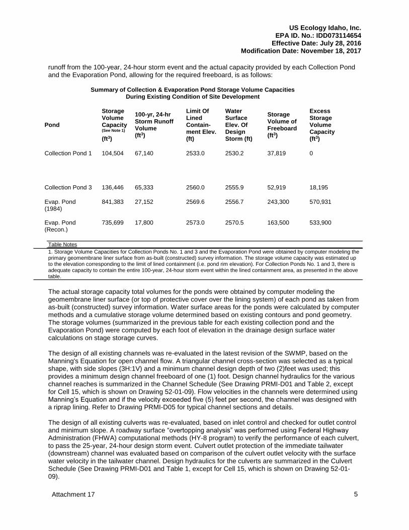
runoff from the 100-year, 24-hour storm event and the actual capacity provided by each Collection Pond and the Evaporation Pond, allowing for the required freeboard, is as follows: Summary of Collection & Evaporation Pond Storage Volume Capacities During Existing Condition of Site Development
Pond
Storage Volume Capacity (See Note 1) (ft3)
100-yr, 24-hr Storm Runoff Volume (ft3)
Limit Of Lined Contain-ment Elev. (ft)
Water Surface Elev. Of Design Storm (ft)
Storage Volume of Freeboard (ft3)
Excess Storage Volume Capacity (ft3)
Collection Pond 1
104,504
67,140
2533.0
2530.2
37,819
0
Collection Pond 3
136,446
65,333
2560.0
2555.9
52,919
18,195
Evap. Pond (1984) Evap. Pond (Recon.)
841,383 735,699
27,152 17,800
2569.6 2573.0
2556.7 2570.5
243,300 163,500
570,931 533,900
Table Notes
1. Storage Volume Capacities for Collection Ponds No. 1 and 3 and the Evaporation Pond were obtained by computer modeling the primary geomembrane liner surface from as-built (constructed) survey information. The storage volume capacity was estimated up to the elevation corresponding to the limit of lined containment (i.e. pond rim elevation). For Collection Ponds No. 1 and 3, there is adequate capacity to contain the entire 100-year, 24-hour storm event within the lined containment area, as presented in the above table.
The actual storage capacity total volumes for the ponds were obtained by computer modeling the geomembrane liner surface (or top of protective cover over the lining system) of each pond as taken from as-built (constructed) survey information. Water surface areas for the ponds were calculated by computer methods and a cumulative storage volume determined based on existing contours and pond geometry. The storage volumes (summarized in the previous table for each existing collection pond and the Evaporation Pond) were computed by each foot of elevation in the drainage design surface water calculations on stage storage curves. The design of all existing channels was re-evaluated in the latest revision of the SWMP, based on the Manning's Equation for open channel flow. A triangular channel cross-section was selected as a typical shape, with side slopes (3H:1V) and a minimum channel design depth of two (2)feet was used; this provides a minimum design channel freeboard of one (1) foot. Design channel hydraulics for the various channel reaches is summarized in the Channel Schedule (See Drawing PRMI-D01 and Table 2, except for Cell 15, which is shown on Drawing 52-01-09). Flow velocities in the channels were determined using Manning’s Equation and if the velocity exceeded five (5) feet per second, the channel was designed with a riprap lining. Refer to Drawing PRMI-D05 for typical channel sections and details. The design of all existing culverts was re-evaluated, based on inlet control and checked for outlet control and minimum slope. A roadway surface “overtopping analysis” was performed using Federal Highway Administration (FHWA) computational methods (HY-8 program) to verify the performance of each culvert, to pass the 25-year, 24-hour design storm event. Culvert outlet protection of the immediate tailwater (downstream) channel was evaluated based on comparison of the culvert outlet velocity with the surface water velocity in the tailwater channel. Design hydraulics for the culverts are summarized in the Culvert Schedule (See Drawing PRMI-D01 and Table 1, except for Cell 15, which is shown on Drawing 52-01-09).
US Ecology Idaho, Inc. EPA ID. No.: IDD073114654
Effective Date: July 28, 2016 Modification Date: November 18, 2017
Attachment 17 6
D.4.a List of Acceptable Wastes
All surface impoundments are currently permitted to manage the RCRA wastes listed in Section A, provided the wastes do not exhibit concentrations of hazardous constituents above the land disposal restrictions (LDRs) described in 40 CFR Part 268 and are not ignitable, reactive, corrosive (e.g. D001, D002 or D003) or subject to the requirements of 40 CFR 264 Subpart CC for volatile organics. Liquid waste for treatment in the Evaporation Pond initially comes from the facilities Wastewater Treatment tanks, the Collection Ponds, the leachate treatment system, or off-site generators. Waste from the Evaporation Pond may be transferred to Ponds 1, and 3, if necessary for water balance requirements. Prior to discharge of liquid wastes into any of the ponds, the waste and pond compatibility are determined in accordance with the WAP.
D.4.b. Exemption Requests
No exemption is requested.
D.4.b.(1) Liner System Description
All three (3) surface impoundments were constructed in the summer of 1984. As such, the minimum technology design requirements described under 40 CFR §264.221(c) do not apply to these impoundments. However, the impoundments were designed and constructed to exceed the requirements of 40 CFR §264.221(a). The reconstructed Evaporation Pond has been designed to meet the minimum technology requirments of 40 CFR §264.221(c).
D.4.b.(1)(a) Collection Pond #’s 1 and 3
The Collection Ponds each have an engineered lining and leachate collection system (leak detection, collection, and removal system (LDCRS)) along their base (floor), as shown on Drawing # PRMI-D06 and -D07. The LDCRS is the flow zone between the primary and secondary liners which collects liquids that may potentially leak through the primary liner and conveys them to the sump (leachate collection vault). The LDCRS consist of the following components (from bottom to top):
Liner sub-grade - Native subsoil
Bedding material - Geotextile fabric
Secondary synthetic liner – 40 mil HDPE material
Leachate, collection and removal zone - 12 in. of free-draining granular material, with a perforated collection pipe system
Primary synthetic liner - 60 mil HDPE
Protective cover layer (bottom of Collection Pond 1 only) - Cobbles over sand (varying thickness), separated by a geotextile filter fabric
The Collection Ponds have interior side slopes varying from two (2) horizontal to one (1) vertical (2H:1V) to approximately 6H:1V. The engineered lining and leachate collection system along the side slopes of the Collection Ponds consist of the following (from bottom to top):
Liner sub-grade - Native subsoil
Bedding material - Geotextile filter fabric
US Ecology Idaho, Inc. EPA ID. No.: IDD073114654
Effective Date: July 28, 2016 Modification Date: November 18, 2017
Attachment 17 7
Secondary synthetic liner - 40 mil HDPE
Leachate, collection and removal zone - Drainage net/Primary synthetic liner – 60 to 80 (pond #3) mil HDPE.
In 1993, a new 80 mil HDPE primary liner was installed in Collection Pond # 3 directly over the original primary liner. The original primary liner was cut and left in place. Synthetic drainage net material was used as the leak detection, collection, and removal system rather than natural granular material because of its ease of placement on the side slopes and its high hydraulic conductivity.
D.4.b.(1)(b) The Evaporation Pond
The Evaporation Pond has an engineered LDCRS along its base (floor) as shown on Drawing #PRMI-L41. The LDCRS consists of the following (from bottom to top):
Liner sub-grade - Native subsoil;
Secondary synthetic liner – 40 mil HDPE;
Leachate, collection and removal zone -12 in. to 18 in. of free draining granular material with a perforated collection pipe system;
“Old” primary synthetic liner – 60 mil HDPE, cut/left in place where “New” was placed;
Protective cover layer - 12 in. soil liner over four (4) in. to six (6) in. of granular material;
“New” primary synthetic liner – 80 mil HDPE over a portion of the Pond; and During installation of the new primary liner, the old primary liner was cut and left in place.
The engineered lining and leak detection, collection, and removal system along the side slopes of the Evaporation Pond consists of the following (from bottom to top):
Liner sub-grade - Native subsoil;
Secondary synthetic liner – 40 mil HDPE;
Leachate, collection, and removal zone Drainage net;
“Old” primary synthetic liner – 60 mil HDPE, cut and left in place when “New” was placed;
Protective cover layer – 12 in. primary soil liner (to elevation 2560 ± only); and
“New” primary synthetic liner - 80 mil HDPE material over a portion of the Pond. During installation of the new primary liner in sections, the old primary liner was cut and left in place. Synthetic drainage net material was used as the leak detection, collection, and removal system rather than natural granular material because of its ease of placement on the side slopes and its high hydraulic conductivity. The Evaporation Pond has interior side slopes varying from 3H:1V to approximately 6H:1V. The exterior side slopes of the Evaporation Pond dikes are 2.5H:1V. The relatively flat side slopes (6H:1V) are used as access ramps for sediment removal and repair operations. If necessary, repair operations will be conducted according to Section D.4.f.(5). The liner components associated with the reconstructed Evaporation Pond are described in Appendix D.4.11.
D.4.b.(2) Liner System Location Relative to High Water Table
For all surface impoundments, separation distances exceed 100 ft. between the lowest point of the synthetic liner and the uppermost aquifer beneath it. As shown in Section E, the depth to the uppermost aquifer in the vicinity of the surface impoundments ranges from approximately 135 ft. to 190 ft. below the present ground surface.
US Ecology Idaho, Inc. EPA ID. No.: IDD073114654
Effective Date: July 28, 2016
Attachment 17 8
D.4.b.(3) Loads on Liner System
D.4.b.(3)(a) Pressure Gradients
Based on laboratory tests and manufacturer’s data (contained in Appendix D.4.3), the primary HDPE liner can support static, uniform loads of 4,000 psi without tearing. This allowable static loading greatly exceeds the anticipated maximum vertical static stress at the surface impoundment base which is estimated to be less than 10 psi. The estimated static pressure is based on the 10 vertical feet of liquid/sludge material with an average in-place density of 80 pounds per cubic foot (pcf). Based on the soil characteristics of the site, bottom heave and slope stability are not expected to produce undue stress on the liner. HDPE has superior tear resistance compared to other common flexible membrane liners. Additional data on tear resistance from a manufacturer appear in Appendix D.4.3.
D.4.b.(3)(b) Installation Stresses
Inspections of the surface impoundment liners indicated that the liner materials do not exhibit “snare drum” effects that are caused by the contracting of the liners in the colder temperatures during the winter months. In addition, the tensile physical properties of HDPE, as presented in Appendix D.4.3 indicate a minimum elongation of 500% before break. Because the HDPE liners are able to withstand temperature extremes and retain their elastic qualities, installation stresses were minimal.
D.4.b.(3)(c) Operational Stresses
The 6H:1V interior side slopes of the impoundments are used as access ramps. Operational stresses will be minimized by allowing only foot traffic on the liners.
D.4.b.(4) Liner System Coverage
The HDPE liners cover the entire bottom surfaces and side slopes of each surface impoundment. Drawing #’s PRMI-D06, -D07, and -L41 show plans and typical sections of the engineered liner systems.
D.4.b.(5) Liner System Exposure Prevention
The primary liners are exposed to the general climatic conditions of the area for a period of time during installation and treatment operations; this exposure should have no detrimental effects. The polymeric HDPE material has good weathering-resistant characteristics as described below:
Water - Very low water absorption capacity (< 0.1%);
Cold - Strength increases with temperature decrease;
Heat - Full strength is maintained up to 90OC; and
Ultraviolet sunlight - HDPE containing carbon black has shown no change in mechanical properties when exposed to UV test conditions.
Examples of manufacturer’s test results are documented in Appendix D.4.3. As described in Section F, the exposed liners are regularly inspected for signs of deterioration and to assess the integrity of the liners.
D.4.c Liner System - Foundation
US Ecology Idaho, Inc. EPA ID. No.: IDD073114654
Effective Date: July 28, 2016 Modification Date: November 18, 2017
Attachment 17 9
D.4.c.(1) Foundation Description
In 1984, the sub-grades for the surface impoundments were excavated/constructed into the native soils (a gravelly, silty sand). Sub-grade (top of secondary HDPE liner) elevations for the impoundments are shown on Drawing #’s PRMI-D06, -D07 and -L41.
D.4.c.(2) Subsurface Exploration Data
Appendix D.6.1 includes the Construction Certification Report. This report summarizes the results of observations and testing of earthwork conducted during construction of PCB Trench 5, Phase 2, including field and laboratory testing. As the soils present do not vary significantly across the facility, the native sub-soils that are present beneath the surface impoundments are of similar characteristics to those observed during the construction of PCB Trench 5, Phase 2. These soils consist of gravelly, silty sand that gradually grades to clean, poorly graded sand. Additional information describing the geology and hydrogeologic conditions present at the facility is included in Section D.6.d.(2) and in Section E.
D.4.c.(3) Laboratory Subsurface Testing Data
Geotechnical laboratory testing data for facility soils are described in Section D.6.d.(2).
D.4.c.(4) Engineering Analyses
Geotechnical calculations and engineering analyses for the surface impoundment foundations are included in Appendix D.4.8. As shown in this appendix, engineering analyses were performed for bearing capacity of the bases of landfill Cells 5 and 14 and the capacity of soil liners to support loads for Cells 5 and 14. These analyses are applicable to the surface impoundment foundations as the soils across the facility are generally consistent. Additional discussions regarding testing of site soils are provided in Appendix D.6.5.
D.4.d Liner Systems – Liners
D.4.d.(1) Synthetic Liners
General information (thickness, type and material) describing the synthetic liners present in the surface impoundments is provided in Section D.4.d. The original liners were manufactured by National Seal Company. The new primary liner for the Evaporation Pond was also manufactured by National Seal Company, while the new primary liner for Collection Pond # 3 was manufactured by Gundle Lining Systems (now GSE). Data describing the material specifications for these liners are contained in Appendix D.4.3.
D.4.d.(1)(a) Synthetic Liner Compatibility Data
The primary synthetic liner is in direct contact with hazardous wastes. Leachate and chemical compatibility data for HDPE liners are presented in Appendices D.4.4 and D.4.5, respectively. These data indicate that the liners are compatible with the wastes placed in the impoundments. Prior to submittal of the facility’s original Part B Permit Document in 1987, a liner chemical compatibility test program to test the effects of five (5) synthetic waste streams on two (2) different brands of 60 mil HDPE liner material was completed. The synthetic waste streams were representative of the general types of wastes that were managed at the facility. A copy of the test program report is included in
US Ecology Idaho, Inc. EPA ID. No.: IDD073114654
Effective Date: July 28, 2016
Attachment 17 10
Appendix D.4.4. In general, the test results indicated that the HDPE liner is compatible with the potential waste streams. Since completion of these tests, the LDRs were promulgated under 40 CFR Part 268. As a result of the promulgation of the LDRs, the concentrations of hazardous constituents managed in the surface impoundments and landfills have decreased significantly. Therefore, the five waste streams used in the 1987 liner chemical compatibility test program represent higher strength wastes than those currently managed at the facility. As such, the results of these tests are still applicable to current operations. Relative to radioactive liquids that would be placed in the Surface Impoundments, the following provides an analysis on the impacts to the liner: The contact dose rate for a slab of depleted uranium is known to be 200 mrad/hr. This dose is due to the beta emissions of its two immediate progeny, thorium-234 and proctatinium-234m. There are nine beta emitters in the decay chain of uranium-238. Over 99% of the dose the uranium and its progeny could deliver to the liner would be from beta emissions. The beta emissions from each of the progeny would deliver a dose of approximately 0.02 mrad/hr. if it were in equilibrium with the parent nuclide, uranium-238, and at the concentration allowed by the WAC. The instantaneous dose rate to the liner would be 0.18 mrad/hr. The annual dose to the liner would be 1.67 rad. HDPE used as insulation for electrical wires is advertised to have a radiation resistance of 7E+6 rads. This indicates a potential lifetime for the liner, based solely on dose, of 4.2 million years. It is also worthy of note that 40 CFR 192, Health and Environmental Protection Standards for Uranium and Thorium Mill Tailings, requires the same containment system for uranium mill tailings as are required for RCRA wastes. Uranium mill tailings contain from 25 to 100 times higher concentrations of the entire beta emitting progeny of uranium-238 than the USEI WAC allows for receipt at the facility.
D.4.d.(1)(b) Synthetic Liner Strength
The basic mechanical and physical properties of HDPE can be summarized as follows:
High tensile strength;
Good elastic deformation;
Good plastic deformation;
Good relaxation properties;
Good stress crack resistance; and
Good resistance to aging. To assure consistent mechanical properties, the manufacturer closely monitors the density of HDPE. Typical data on the physical properties of an HDPE liner from a major manufacturer are presented in Appendix D.4.3.
D.4.d.(1)(c) Synthetic Liner Bedding
As shown on Drawing #’s PRMI-D06, -D07 and -L41, the synthetic liners installed have soil and/or geotextile bedding materials above and below the liners to provide additional protection of the liners during installation and operation of the surface impoundments. The soil bedding materials consisted of the native gravelly, silty sands present across the site. These soils were excavated, fine graded, and compacted as described in the technical specifications contained in Appendix D.4.1. Liners were installed using procedures similar to those described in Appendix D.4.1 to protect the liners from potential damage
during installation. Descriptions of the liner systems for the Collection Ponds and the Evaporation Pond were provided previously in Section D.4.d.(1).
US Ecology Idaho, Inc. EPA ID. No.: IDD073114654
Effective Date: July 28, 2016 Modification Date: November 18, 2017
Attachment 17 11
D.4.d.(2) Soil Liners
Because the impoundments were constructed in the summer of 1984, the requirements of 40 CFR §264.221(c)(1)(i)(B) do not apply.
D.4.e Liner System-Leachate Detection System
D.4.e.(1) LDCRSs
Because the Ponds 1 and 3 were constructed in the summer of 1984, they are not required to have leak detection systems described under 40 CFR §264.221(c)(2). However, as described previously in Section D.4.b, these ponds do have leak detection, collection and removal systems meeting those requirements. The reconstructed Evaporation Pond will have a leak detection, collection and removal system that meets current minimum technology requirements.
D.4.e.(1)(a) Collection Pond #’s 1 and 3 and Original Evaporation Pond
The layout for the LDCRS for each of the surface impoundments is shown on Drawing # PRMI-D06, -D07 and -L41. The drainage layer detects and collects leakage escaping through the primary liner and conveys it to collection sumps located under the impoundments. The base of each surface impoundment is graded to drain toward the collection sumps at a 2% slope (minimum). The collection pipes in the Evaporation Pond and Collection Pond #1 and #3 are also constructed at a minimum slope of 2%. These collection pipes are four (4) in. diameter (minimum) perforated HDPE pipes that are placed within the 12 in. to 18 in. leakage collection drain layer. The four (4) in. diameter HDPE pipes are adequate for gravity drainage of leakage to the sumps. Design calculations for the collection pipes systems are included in Appendix D.4.8. The collection sumps include HDPE riser pipes in each surface impoundment. Sumps are located in the low points as indicated on Drawing #’s PRMI-D06 and -L41. Drawing # PRMI-D06, -D07, and -L41 depict cross-sections of the liner system and sumps. As shown in these drawings, the riser pipes extend up the side slopes from below the base to the top of the surface impoundment crest. The riser pipes penetrate the primary liners at the tops of the side slopes at the edges of the impoundments, which is well above the maximum allowable liquid level. As stated, the four (4) in. (minimum) diameter perforated collection pipes and fittings are constructed of HDPE similar to those described in Appendix D.4.1 and the pipes have sufficient strength to support the loads applied to them over the operating life of the surface impoundments. The collection sumps are approximately five (5) ft. long by five (5) ft. wide by three (3) ft. deep, are filled with granular material surrounding a three (3) ft. high, perforated, 24 in. diameter HDPE vault. The 24 in. diameter HDPE vaults are set in concrete bases placed over a protective HDPE slip sheet to prevent puncture of the secondary liner. Access to the vaults for monitoring leakage levels and for removing leakage is provided by a 12 in. diameter HDPE side slope riser pipe. The four (4) in. (minimum) diameter collection pipes are connected to the 24 in. diameter HDPE vaults. The LDCRS at the base and side slopes is described in Section D.4.c.(1). The side slope net is a permeable synthetic mesh that allows migration of leachate along the slope to the base LDCRS. The drainage nets installed in the surface impoundments have transmissivity values that typically exceed 3 x
US Ecology Idaho, Inc. EPA ID. No.: IDD073114654
Effective Date: July 28, 2016 Modification Date: November 18, 2017
Attachment 17 12
10-4 m2/sec. Section 6 of Appendix D.4.1 provides additional information on flow zone and collection pipe placement. Typical design calculations are included in Appendix D.4.8. The LDCRSs for the Evaporation Pond and Collection Ponds #1 and #3 each consist of a drainage net on the side slopes and a free-draining granular material and collection pipes with a stone annulus wrapped in polypropylene geotextile filter on the bases. The geotextile filter minimizes the clogging of the stone annulus. The granular material minimizes the infiltration of fine grained particles if a leak occurs in the liner. The collection pipes are covered with approximately six (6) in. of ¾ in. to two (2) in. coarse aggregate. This size aggregate does not enter and/or block the ⅜ in. diameter pipe perforations. Where possible, four (4) in. (minimum) diameter clean-out lines are provided for the leachate pipes. Drawing #’s PRMI-D06 and -L41 show the location of these clean-out lines for the various impoundments. The collection sumps of the Collection Ponds and the Evaporation Pond are inspected in accordance with Section F and the liquid levels in the collection sumps are measured as part of the surface impoundment inspections. A gauge is lowered down the HDPE riser pipe to the leachate collection sump in each surface impoundment to measure the level of liquids (if any). If liquid is found in a zone at a depth of 12 in. or more, it is pumped dry to the extent practical. A backup pump is maintained at the facility. The liquid removed from the collection sumps is pumped to containers or tank trucks that are weighed before and after pumping, through calibrated containers or tanks, or through a flow meter to determine the volume of leachate removed. The collected liquid may be returned to a surface impoundment, transferred to a tank, or other authorized unit. A chronological record of pumping events and volume of liquid removed is maintained in the operating record. The pumping data are analyzed to determine the leakage rate and the calculated leakage rate is compared to the ranges of leakage established in the Response Action Plan (RAP) included in Section M. As described in the RAP, various leakage rates for each unit trigger various levels of response actions (such as repairing the primary liner system, modifying daily operating procedures and notifying the IDEQ).
D.4.e.(1)(b) Reconstructed Evaporation Pond
The LDCRS for the reconstructed Evaporation Pond is described in detail in Appendix D.4.11.
D.4.f Liner System - Construction and Maintenance
D.4.f.(1) Material Specifications
D.4.f.(1)(a) Synthetic Liners
See Section D.4.d.(1).
D.4.f.(1)(b) Soil Liners
See Section D.4.d.(2).
D.4.f.(1)(c) Leachate Detection System
US Ecology Idaho, Inc. EPA ID. No.: IDD073114654
Effective Date: July 28, 2016 Modification Date: November 18, 2017
Attachment 17 13
See Section D.4.e.
D.4.f.(2) Construction Specifications
The construction specifications, similar to those followed during construction of the surface impoundments are included in Appendix D.4.1. Construction specifications for the reconstructed Evaporation Pond are included in Appendix D.4.11.
D.4.f.(3) Construction Quality Control Program
The Construction Quality Assurance (CQA) Plan is included in Appendix D.4.2. This CQA Plan provides for any subsequent repairs to or replacements of the liner systems for the landfill cells and surface impoundments to meet or exceed the design criteria, plans, and specifications. Additionally, this CQA plan demonstrates that the USEPA’s Technical Guidance Document: Quality Assurance and Quality Control for Waste Containment Facilities (September 1993) has been followed. As these surface impoundments liner systems were installed prior to the issuance of the USEPA CQA guidance, the liners were installed in accordance with a previous CQA plan prepared by the designer of the impoundments, Conversion Systems, Inc. The CQA Plan for the reconstructed Evaporation Pond is included in Appendix D.4.11.
D.4.f.(4) Maintenance Procedures for the Leachate Detection System
The LDCRSs for the surface impoundments are inspected as described in Section D.4.l and in Section F. Based on the results of these inspections, repairs to the affected component(s) will be made. Because of the nature of the LDCRSs (i.e., in-place underground field systems), routine maintenance procedures are not necessary except for the pumps. These are maintained and repaired as necessary.
D.4.f.(5) Liner Repairs During Operation
Upon observation of damage to the liner system, the placement of liquids in the surface impoundment is immediately restricted. The liquid level is lowered, as necessary to maintain a level below the damaged area to allow for repairs. An inspection to assess the damage is performed. The inspection procedures are as follows:
If the damage is located on the base, the materials overlying the primary liner will be carefully removed a minimum of 24 in. beyond the damage in all directions to provide a working area. If the cover material is saturated, barriers, absorbents and/or the vacuum truck are used to maintain the work area in a dry condition and to minimize leakage to the LDCRS or underlying base material.
Rope or other appropriate ladders are used to provide access for the inspector, repair crew, and qualified, certifying engineer.
The primary liner is cleaned and dried. If the primary liner is deformed but not penetrated, the damage is repaired as described below. However, if the primary liner is penetrated, the liner is carefully cut and removed a minimum of 12 in. beyond the damage in all directions to expose the LDCRS.
If the LDCRS materials (drainage net on the side slopes and granular material and geotextile fabric on the base) are penetrated or disturbed, the LDCRS materials are cut and removed a minimum of 12 in. beyond the damage in all directions to expose the secondary liner.
The secondary liner is then cleaned and dried. If the secondary liner is deformed but not penetrated, the damage is repaired as described below. However, if the secondary liner is
US Ecology Idaho, Inc. EPA ID. No.: IDD073114654
Effective Date: July 28, 2016 Modification Date: November 18, 2017
Attachment 17 14
penetrated, obvious visible contamination is removed, and the underlying base materials sampled. Samples are analyzed for indicator parameters, and the results are compared with risk-based concentrations for these same parameters. Risk-based soil concentrations are described in Section I. Soils are considered clean as described in Section I.
Temporary repairs are made to provide containment until the permanent repairs can be completed. Temporary HDPE patches are heat-seamed over the damage and in addition, duct tape can be used to further secure and seal the temporary patch. The liquid in the surface impoundment is not allowed to rise above the level of the temporary repair. However, liquid may be discharged into the temporarily repaired impoundment to a level not to exceed 24 in. below the lowest point of the temporarily repaired area. Permanent repairs may be delayed because of the following conditions:
Liner temperature is below 35OF;
Precipitation or high humidity;
High winds and/or dusty conditions;
Qualified HDPE welder not available;
Qualified certifying engineer not available; and
Results of soil sampling analyses not received (if secondary liner was penetrated). All permanent repair work is performed only in the presence of the qualified certifying engineer, as described below:
If sub-base soil was removed, it is replaced and compacted with similar materials.
Prior to any welding repair activities, the person who is to perform the repair must make a satisfactory test weld. This test requires preparing and welding together two pieces of HDPE material that are at least three (3) ft. long. Three one (1) in. wide samples are removed and tested in peel until failure. As an alternative, test welds may be performed in accordance with the requirements described in the CQA Plan (see Appendix D.4.2). A passing test requires the sheet material to fail before the weld. Deformations in the HDPE liner are repaired by roughening the damaged and surrounding area with sand paper. A bead of extruded HDPE is then placed over penetrations in the HDPE. Liners are patched with material of the same thickness and type as the damaged liner. The patch is cut to extend beyond the damaged area by at least four (4) in., and all corners are rounded. The liner surface and patch material are then cleaned and dried. With the hot air gun and roller, the patch is heat seamed to the liner so that the patch lies flat and without wrinkles. The surface to which the patch will be extrusion welded is roughened with sand paper and the patch immediately welded. When the weld has cooled, a soap solution is applied to the seams, and the repair is vacuum tested, if possible. Should a leak be detected, the defective weld is roughened, re-welded, and re-tested. The procedure continues until a leak free repair has been made.
Drainage net, if clean, may be reused. If required, additional net will be placed over the repair to overlap underlying pieces a minimum of two (2) in., and secured with nylon cable ties.
Geotextile fabric, if clean, may be reused. If required, additional fabric is placed over the repair to overlap underlying pieces a minimum of four (4) in., and heat seamed together.
Granular materials and cover soils will be replaced with similar materials and to the original thickness.
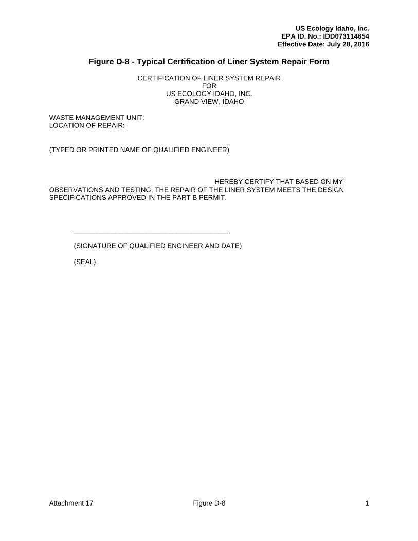
Upon completion and testing of the repair, the qualified certifying engineer completes the certification form shown on Figure D-8.
US Ecology Idaho, Inc. EPA ID. No.: IDD073114654
Effective Date: July 28, 2016 Modification Date: November 18, 2017
Attachment 17 15
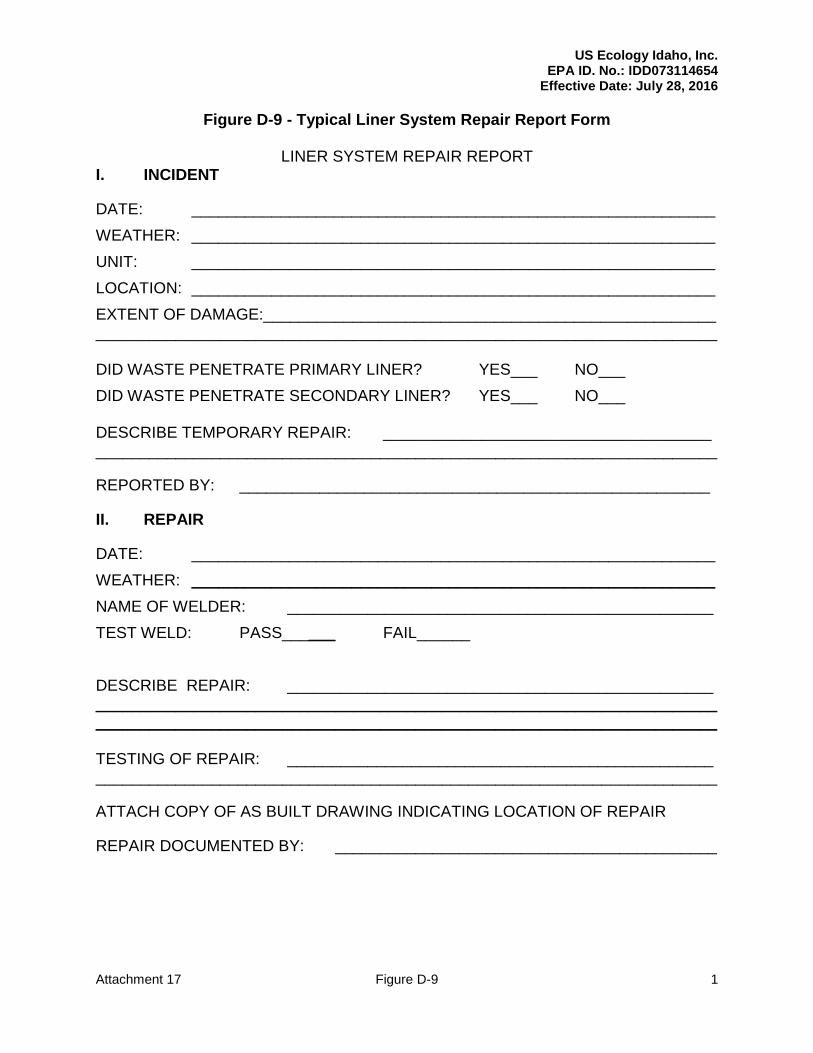
The inspection, assessment, repair, and testing of the damaged liner system will be documented on the liner system repair report form shown on Figure D-9. The repaired unit may then be returned to normal service.
D.4.g Prevention of Overtopping
Overtopping of the surface impoundments is prevented by maintaining sufficient freeboard in each of the impoundments. Evaluations of all surface impoundments were performed and the maximum wave height from wind was determined to be 2.8 feet for the Evaporation Pond. Similar calculations for the Collection Ponds indicate the maximum wave height for these impoundments is less than 2.8 ft. Therefore, freeboard for the impoundments is generally maintained at least 2.8 ft. below the top of liner sidewall when used to manage wastes. The Evaporation Pond has a small drainage area that generates a run-off volume from the 25-year, 24-hour storm of less than 5% of the designed Evaporation Pond capacity. Although the Evaporation Pond is primarily used for the solar evaporation of aqueous wastes, it has sufficient capacity to handle this excess run-off. If necessary, the level in the Evaporation Pond can be controlled manually by pumping to the Collection Ponds. All of the surface impoundments are inspected to avoid overtopping. These inspections are performed as described in Section F. Before a Collection Pond encroaches on its’ freeboard, the water in the Collection Pond is transferred to the Evaporation Pond. If necessary, the surface impoundment levels can be lowered by transporting excess water from the surface impoundments by the pump and pipe system, tank trucks, or vacuum trucks. The freeboard requirements for the reconstructed Evaporation Pond are outlined in Appendix D.4.11.
D.4.h Dike Stability
The Evaporation Pond is the only surface impoundment which incorporates dikes into its sidewall construction. The other surface impoundments were excavated below original grade and, therefore, do not have dikes. In May 1998, Geosystems Consultants, Inc. of Fort Washington, Pennsylvania, prepared a Geotechnical Investigation report for the surface impoundments and landfill units. A copy of this report is included in Appendix D.4.8. As described in this report, the following information/analyses were presented/performed:
Geotechnical (i.e., general geology, subsurface conditions and groundwater) conditions of the facility;
A discussion of site seismicity; and
Discussions of laboratory test results for: o Consolidation tests of in-situ soils; o Triaxial shear strength tests of in-situ soils; o Shear strength tests of compacted site soils; o Shear strength tests of un-stabilized and stabilized waste; o Slope stability analyses under both static and pseudo-static seismic conditions; o Veneer system (i.e., final cover system) static and seismic stability analyses; and o A discussion of factors of safety for slopes under static and seismic conditions.
Additional stability analysis was performed for the reconstructed Evaporation Pond. Stability analysis results are presented in Appendix D.4.11.
D.4.h.(1) Engineer’s Certification
US Ecology Idaho, Inc. EPA ID. No.: IDD073114654
Effective Date: July 28, 2016 Modification Date: November 18, 2017
Attachment 17 16
Included in Appendix D.4.10 is a certification by a qualified engineer attesting to the structural integrity of the surface impoundment dikes in accordance with 40 CFR §264.226(c). The impoundment names on the certifications are the names originally used when the impoundments were built. Landfill Pond #1 corresponds to Pond #1; Process Area Pond corresponds to Pond #3; and Evaporation Pond #1 corresponds to the Evaporation Pond.
D.4.h.(2) Dike Design Description
A description of the Evaporation Pond dike design layout and materials of construction is provided in Appendix D.4.8. The capability of these dikes to withstand failure from expected static and dynamic loading is also described in this appendix.
D.4.h.(3) Erosion and Piping Protection
The Evaporation Pond dikes were designed and constructed to minimize erosion and prevent failure from excessive erosion from:
Rainfall;
Surface water run-off;
Contact between impounded wastes and the dikes;
Potential leakage through the dikes; and
Potential leakage along conduits or structures through the dikes. Because of the relatively short length of the dike slopes and the lack of run-off from adjacent areas over the dikes, the dike erosion potential from rainfall and surface water run-off is minimal. In addition, the coarse, granular nature of the materials used to construct the outer slopes of the dike provides a surface that is not easily eroded. Because of the double HDPE liner system design of the Evaporation Pond, impounded wastes should not contact the dike materials. The dikes and liner system are inspected as described in Section F. Any leaks detected in the liner system will be repaired as described in Section D.4.f.(5). Therefore, potential leakage through the dikes should be negligible and should not cause any significant erosion of the dikes. There are no conduits or structures through the dikes. As such, there is no potential leakage along conduits or structures through the dikes.
D.4.h.(4) Subsurface Soil Conditions
The engineering characteristics of the dike foundation materials were verified through testing and subsurface investigations as described in Section D.4.h and Appendix D.4.8.
D.4.h.(5) Stability Analysis
A description of, and the results from, applicable stability analyses are described in Appendices D.4.8 and D.4.11.
D.4.h.(6) Strength and Compressibility Results
US Ecology Idaho, Inc. EPA ID. No.: IDD073114654
Effective Date: July 28, 2016 Modification Date: November 18, 2017
Attachment 17 17
The results of strength and consolidation tests on the dike materials, together with a description of the sampling procedures and test methods, are described in Appendix D.4.8.
D.4.h.(7) Dike Construction Procedures
Soil specifications for dike modification are contained in the Evaporation Pond Reconstruction Engineering Report, located in Attachment 17.
D.4.h.(8) Dike Construction Inspection Program
The CQA Plan for dike modification is contained in the Evaporation Pond Reconstruction Engineering Report, located in Attachment 17.
D.4.i Action Leakage Rate
As the original surface impoundments are not subject to the requirements of 40 CFR §264.221(c) or (d), approved action leakage rates (ALRs) for the impoundment leak detection systems are not required. However, as the impoundments do have LDCRSs in place, the RAP establishes ALRs and response actions for each impoundment. The ALR calculation for the reconstructed Evaporation Pond is presented in Appendix D,4.11 and is summarized in Section M.
D.4.j Response Actions
The surface impoundment collection systems are routinely checked as described in Section F. In the event liquid is found, the following actions are taken: The liquid will be removed using the following procedures:
Pump the zone dry to the extent practical;
Determine the volume of leachate removed;
Compare volume of liquid removed to ranges of leakage defined in the RAP; and
Initiate response actions as established in the RAP, if required. The liquid is handled by one of the following methods, following analysis in accordance with the WAP (depending on amount and analysis):
Return it to a surface impoundment for solar evaporation;
Stabilize the leachate and dispose within the landfill area;
Ship it to an authorized TSD facility;
Utilize liquid in the stabilization process;
Store liquid in a tank for future treatment; and
Log the activity in the facility operating record.
D.4.k Monitoring and Inspection
Surface impoundments are inspected for:
Run-on diversion and run-off control systems;
Leak detection, collection and removal system;
Freeboard level; and
US Ecology Idaho, Inc. EPA ID. No.: IDD073114654
Effective Date: July 28, 2016 Modification Date: November 18, 2017
Attachment 17 18
Potential leaks or deterioration in the earthen dikes. Periodic inspections of surface impoundment operations also include the following:
Haul and access roads for accessibility and damage due to excessive run-off;
Run-off/run-on control;
Spillage on haul roads;
Dikes;
Safety and emergency response equipment; and
Odors. Section F contains the details of the surface impoundment inspection program.
D.4.l Emergency Repairs; Contingency Plans
The procedures followed if emergency repairs to a surface impoundment are required are described in the Contingency Plan which is located in Section G.
D.4.m Closure and Post-Closure Care
The surface impoundments will be removed from service in a sequential manner that is coordinated with the total facility closure. Section I provides details on the closure procedures for each of the surface impoundments.
D.4.n Special Requirements for Ignitable or Reactive Waste
Bulk ignitable or reactive waste liquids and sludge’s meeting the definition of ignitable or reactive waste under 40 CFR 261.21 or 261.23 are not disposed or treated in the surface impoundments. The fingerprint analysis procedures noted in the WAP are used to assure that ignitable or reactive wastes are not accepted for disposal or treatment in surface impoundments.
D.4.o Special Requirements for Incompatible Wastes
Incompatible wastes are not placed in the same surface impoundment.
D.4.p Air Emission Standards
Wastes regulated by Subpart CC of 40 CFR Part 264 are not managed in impoundments at the facility.
US Ecology Idaho, Inc. EPA ID. No.: IDD073114654
Effective Date: July 28, 2016 Modification Date: November 18, 2017
Attachment 17 19
Appendix D.4.11 Evaporation Pond Reconstruction Engineering Report
US Ecology Idaho, Inc. EPA ID. No.: IDD073114654
Effective Date: July 28, 2016
Attachment 17 Figure D-8 1
Figure D-8 - Typical Certification of Liner System Repair Form
CERTIFICATION OF LINER SYSTEM REPAIR FOR
US ECOLOGY IDAHO, INC. GRAND VIEW, IDAHO
WASTE MANAGEMENT UNIT: LOCATION OF REPAIR:
(TYPED OR PRINTED NAME OF QUALIFIED ENGINEER)
___________________________________________ HEREBY CERTIFY THAT BASED ON MY OBSERVATIONS AND TESTING, THE REPAIR OF THE LINER SYSTEM MEETS THE DESIGN SPECIFICATIONS APPROVED IN THE PART B PERMIT.
_________________________________________
(SIGNATURE OF QUALIFIED ENGINEER AND DATE)
(SEAL)
US Ecology Idaho, Inc. EPA ID. No.: IDD073114654
Effective Date: July 28, 2016
Attachment 17 Figure D-9 1
Figure D-9 - Typical Liner System Repair Report Form
LINER SYSTEM REPAIR REPORT I. INCIDENT
DATE: ___________________________________________________________
WEATHER: ___________________________________________________________
UNIT: ___________________________________________________________
LOCATION: ___________________________________________________________
EXTENT OF DAMAGE:___________________________________________________ ______________________________________________________________________ DID WASTE PENETRATE PRIMARY LINER? YES___ NO___
DID WASTE PENETRATE SECONDARY LINER? YES___ NO___ DESCRIBE TEMPORARY REPAIR: _____________________________________ ______________________________________________________________________
REPORTED BY: _____________________________________________________
II. REPAIR
DATE: ___________________________________________________________
WEATHER: ___________________________________________________________
NAME OF WELDER: ________________________________________________
TEST WELD: PASS______ FAIL______
DESCRIBE REPAIR: ________________________________________________ ______________________________________________________________________ ______________________________________________________________________ TESTING OF REPAIR: ________________________________________________ ______________________________________________________________________
ATTACH COPY OF AS BUILT DRAWING INDICATING LOCATION OF REPAIR
REPAIR DOCUMENTED BY: ___________________________________________
RCRA Permit: IDD073114654 US Ecology Idaho
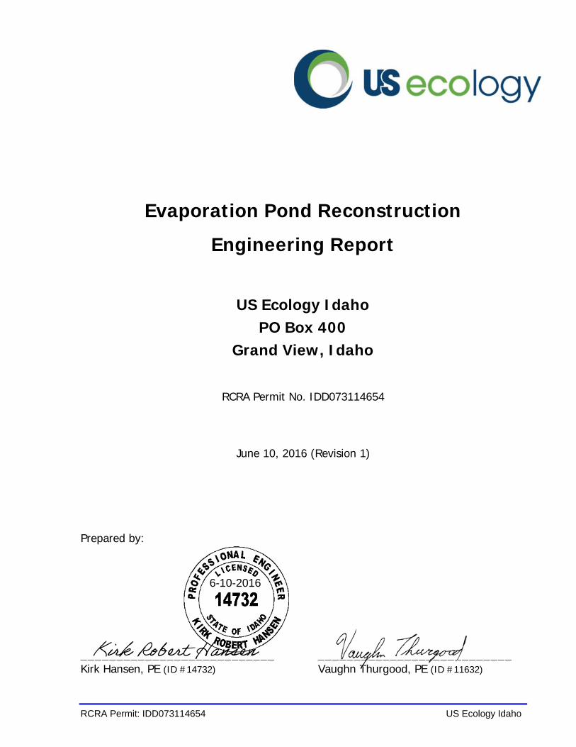
Evaporation Pond Reconstruction
Engineering Report
US Ecology Idaho PO Box 400
Grand View, Idaho
RCRA Permit No. IDD073114654
June 10, 2016 (Revision 1)
Prepared by:
___________________________ ___________________________ Kirk Hansen, PE (ID #14732) Vaughn Thurgood, PE (ID #11632)
6-10-2016
Kirk Robert Hansen
Evaporation Pond Reconstruction
Engineering Report
June 10, 2016
RCRA Permit: IDD073114654 i US Ecology Idaho
TABLE OF CONTENTS
PAGE
1.0 INTRODUCTION ................................................................................. 1
1.1 REPORT OUTLINE ........................................................................................... 1
2.0 PERMITTING ...................................................................................... 3
2.1 POND CONSTRUCTION HISTORY ......................................................................... 3 2.2 REGULATORY DESIGN CRITERIA ......................................................................... 3 2.3 DEMOLITION AND DISPOSAL .............................................................................. 4
3.0 CONTAINMENT ................................................................................... 5
3.1 LINER COMPONENTS ....................................................................................... 5 3.2 LEAK DETECTION SYSTEM ................................................................................. 5 3.3 PERFORMANCE CRITERIA .................................................................................. 6 3.4 OVERTOPPING ............................................................................................... 7 3.5 FOUNDATION STABILITY ................................................................................... 9 3.6 LINER UPLIFT .............................................................................................. 10
4.0 ACTION LEAKAGE RATE (ALR) ......................................................... 11
5.0 FROST PROTECTON AGGREGATES ................................................... 12
5.1 CLIMATE .................................................................................................... 12 5.2 FROST PROTECTION ...................................................................................... 12 5.3 RIPRAP AGGREGATES .................................................................................... 12
6.0 OPERATION AND CLOSURE .............................................................. 13
6.1 WASTE ACCEPTANCE ..................................................................................... 13 6.2 INSPECTION SCHEDULE .................................................................................. 13 6.3 OPERATING LIMITS ....................................................................................... 13 6.4 RESPONSE ACTIONS AND REPAIRS ..................................................................... 13 6.5 CLOSURE ................................................................................................... 13
7.0 CONCLUSIONS ................................................................................. 14
8.0 REFERENCES .................................................................................... 15
APPENDICES
A Drawings
B Calculations
C Construction Quality Assurance (CQA) Plan
Evaporation Pond Reconstruction
Engineering Report
June 10, 2016
RCRA Permit: IDD073114654 1 US Ecology Idaho
1.0 INTRODUCTION
This engineering report outlines the proposed reconstruction of the existing Evaporation Pond unit located at the US Ecology Idaho (USEI) hazardous waste management facility in Grand View, Idaho. The evaporation pond is currently permitted as a surface impoundment for the evaporation of landfill leachate and other liquids.
The original pond liner has been in service for more than 30 years. The pond liner components have deteriorated as a result of climatic exposure and are near terminal service limits. Reconstruction will include the following:
1. Complete liner replacement;
2. Inclusion of a 36-inch compacted clay liner (as required by current RCRA standards); and
3. Inclusion of a 30-inch layer of frost protection aggregates (as required by current RCRA standards).
The operational capacity of the current evaporation pond (holding capacity minus freeboard) is 605,900 ft3. The reconstructed evaporation pond will occupy the same footprint and will have a revised operational capacity of 533,900 ft3, as described herein.
During reconstruction, the landfill leachate will be temporarily routed to Pond 1 and Pond 3, in accordance with the USEI facility permit.
1.1 Report Outline
This report addresses the details of the evaporation pond reconstruction. The report consists of the following key sections:
Permitting – Section 2
This section provides a brief history of the existing evaporation pond and identifies the RCRA regulatory requirements which are applicable for this design.
Evaporation Pond Reconstruction
Engineering Report
June 10, 2016
RCRA Permit: IDD073114654 2 US Ecology Idaho
Containment – Section 3
This section identifies the reconstructed containment components and evaluates their respective regulatory compliance.
Action Leakage Rate (ALR) – Section 4
This section evaluates a minimum action leakage rate for the reconstructed surface impoundment.
Frost Protection Aggregates – Section 5
This section presents rationale for aggregate thickness and other material parameters for the frost protection sand and riprap aggregates.
Operations and Closure– Section 6
This section provides reference to the operating procedures, waste acceptance and closure requirements.
Evaporation Pond Reconstruction
Engineering Report
June 10, 2016
RCRA Permit: IDD073114654 3 US Ecology Idaho
2.0 PERMITTING
2.1 Pond Construction History
The evaporation pond was originally permitted in 1984, and subsequently does not conform to all of the current RCRA requirements. The original pond liner system included the following components (listed from top to bottom):
• 18 inches of protective cover - granular aggregates (floor only)
• Geotextile cushion (floor only)
• 60 mil HDPE geomembrane - primary liner
• 12 inch layer of drainage aggregates (floor only)
• Geonet drainage layer (slopes only)
• 40 mil HDPE geomembrane - secondary liner
In 1999 the liner system for the evaporation pond was modified by installing a 12-inch layer of compacted clay across the floor and up the slope to elevation 2560 feet. The evaporation pond was also lined with an additional 80-mil HDPE geomembrane liner.
2.2 Regulatory Design Criteria
The reconstructed evaporation pond will conform with the RCRA design and operating requirements outlined in 40 CFR §264 – Subpart K – Surface Impoundments. Design improvements will be adopted to bring the unit into conformance with 40 CFR §264.221(c), which states that replacement of an existing surface impoundment unit must include:
§264.221.(c)(1)(i)(B) - A composite bottom liner, consisting of at least two components. The upper component must be designed and constructed of materials (e.g., a geomembrane) to prevent the migration of hazardous constituents into this component during the active life and post-closure care period. The lower component must be designed and constructed of materials to minimize the migration of hazardous constituents if a breach in the upper
Evaporation Pond Reconstruction
Engineering Report
June 10, 2016
RCRA Permit: IDD073114654 4 US Ecology Idaho
component were to occur. The lower component must be constructed of at least 3 feet (91 cm) of compacted soil material with a hydraulic conductivity of no more than 1×10⁻⁷ cm/sec [emphasis added].
Hence, reconstruction of the USEI Evaporation Pond must incorporate a 36-inch compacted clay liner. 40 CFR §264.221.(a)(1) also infers that the clay liner must be protected against the potential negative effects of climatic frost penetration.
2.3 Demolition and Disposal
Prior to reconstruction of the evaporation pond, the remaining liquids and residues will be removed from the evaporation pond and all of the existing liner components will be demolished. The demolished liner components and associated waste residue will be treated and disposed in accordance with the permitted closure plan.
Subgrade sampling and associated background contaminant analysis will be postponed until final closure of the Evaporation Pond unit occurs, except in cases where visual staining and/or other evidence of prior leakage is observed.
Evaporation Pond Reconstruction
Engineering Report
June 10, 2016
RCRA Permit: IDD073114654 5 US Ecology Idaho
3.0 CONTAINMENT
3.1 Liner Components
The floors and sidewalls of the evaporation pond will be dual lined and contain a leak detection collection and removal system (LDCRS). The reconstructed evaporation pond will include the components illustrated on Drawing EP-16-02 (Appendix A). The pond liner components listed from top to bottom will include the following.
• 12-inches Riprap aggregates (side slope) or Cover Gravel aggregates (floor)
• 8 oz. Nonwoven Geotextile Filter (side slope)
• 18-inches Cover Sand aggregates
• 16 oz. Nonwoven Geotextile Cushion
• 60-mil Textured HDPE Geomembrane – Top Liner
• Double Sided Geocomposite – LDCRS Drain
• LDCRS Composite Bottom Liner:
o 60-mil Textured HDPE Geomembrane
o 36-inches Compacted Clay Liner (k≤1x10⁻⁷cm/s)
Likewise, the HDPE geomembrane materials are textured to improve interface friction and stability. Both liner systems extend to an anchor trench located around the perimeter berm.
3.2 Leak Detection System
Surface impoundments require a leachate collection and removal system which also functions as a leak detection system. The LDCRS contains a drainage layer that collects any leaked hazardous constituents. The evaporation pond LDCRS provides transmissivity greater than 3x10⁻⁴ m2/sec and maintains a bottom slope greater than one percent. The performance of the LDCRS system is evaluated separately in Section 4.0 of this report.
Evaporation Pond Reconstruction
Engineering Report
June 10, 2016
RCRA Permit: IDD073114654 6 US Ecology Idaho
3.3 Performance Criteria
The synthetic liner components will be constructed with HDPE materials, similar to the existing evaporation pond and the active landfill liners at the USEI facility. Material specification, installation procedures, testing requirements, and acceptance criteria are contained in the CQA Plan (Appendix C). Calculations related to the design and performance of the evaporation pond are contained in Appendix B. Some of the key design considerations regarding the liner components are described below.
HDPE Geomembranes
Geomembranes in the liner system will consist of high density polyethylene (HDPE) material. HDPE material is the most chemically resistant material available for liner construction. HDPE liners with a 60-mil thickness have historically performed very well and offer a good balance between liner flexibility and survivability.
Geocomposite
Geocomposite drain materials are used to transmit leachate to collection pipes in a manner which maintains less than one foot of maximum hydraulic head on the bottom liner system. The geocomposite consists of a geonet that is bonded with geotextile filter fabric which protects the drain against sedimentation clogging. The geocomposite materials used in the evaporation pond will be double-sided for increased friction and stability.
Specific transmissivity performance criteria for the LDCRS geocomposite layer was selected based upon the following considerations:
• Action Leakage Rate;
• Application specific hydraulic gradients;
• Long-term creep effects related to overburden pressure;
• Long-term clogging effects related to chemical scaling;
• Long-term clogging effects related to biological presence;
Evaporation Pond Reconstruction
Engineering Report
June 10, 2016
RCRA Permit: IDD073114654 7 US Ecology Idaho
• Potential variance in drainage panel orientation; and
• Maximum allowable flow depth is limited to the thickness of the geocomposite (hydraulic head is less than ¼ inch).
Specific engineering analysis related to the performance of the geocomposite material is evaluated in Calculation #3.
Geotextile
Geotextile products are made of polypropylene resins. Geotextiles provide filter separation and may also be used to provide cushioning between aggregate particles that might otherwise puncture an underlying membrane liner.
Compacted Clay Liner
The compacted clay liner is designed to impede migration of potential leakage through the LDCRS geomembrane. The LDCRS geomembrane and compacted clay materials form a composite liner system. Native clay materials located in the project vicinity will be pulverized, screened, moisture conditioned and re-compacted in multiple controlled lifts to form a low permeability (k≤10-7 cm/sec) soil liner. Re-compacted clay materials obtained from the site yield a typical hydraulic conductivity between 10-8 and 10-9 cm/sec.
HDPE Pipes
The LDCRS header pipe, sump manifold, and riser pipe will be constructed with HDPE materials. The header pipe and sump manifold sections will be perforated to allow for liquid transmission in and out of the pipe. Stability analysis was performed for to identify the minimum wall thickness needed to maintain structural stability under the maximum potential loading scenarios, as described in Calculation #2.
3.4 Overtopping
Waste liquids are manually transferred into the evaporation pond, typically by unloading a tanker truck, or by pipe transfer from the on-site leachate treatment facility. The evaporation pond is operated with sufficient freeboard to safeguard against the threat
Evaporation Pond Reconstruction
Engineering Report
June 10, 2016
RCRA Permit: IDD073114654 8 US Ecology Idaho
of overtopping. Calculation #1 indicates the operational capacity of the evaporation pond, including the reserved freeboard volumes.
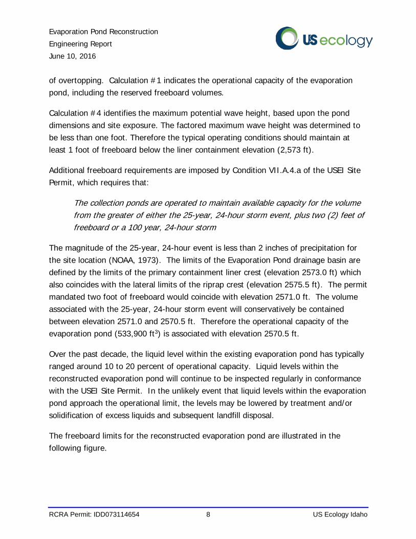
Calculation #4 identifies the maximum potential wave height, based upon the pond dimensions and site exposure. The factored maximum wave height was determined to be less than one foot. Therefore the typical operating conditions should maintain at least 1 foot of freeboard below the liner containment elevation (2,573 ft).
Additional freeboard requirements are imposed by Condition VII.A.4.a of the USEI Site Permit, which requires that:
The collection ponds are operated to maintain available capacity for the volume from the greater of either the 25-year, 24-hour storm event, plus two (2) feet of freeboard or a 100 year, 24-hour storm
The magnitude of the 25-year, 24-hour event is less than 2 inches of precipitation for the site location (NOAA, 1973). The limits of the Evaporation Pond drainage basin are defined by the limits of the primary containment liner crest (elevation 2573.0 ft) which also coincides with the lateral limits of the riprap crest (elevation 2575.5 ft). The permit mandated two foot of freeboard would coincide with elevation 2571.0 ft. The volume associated with the 25-year, 24-hour storm event will conservatively be contained between elevation 2571.0 and 2570.5 ft. Therefore the operational capacity of the evaporation pond (533,900 ft3) is associated with elevation 2570.5 ft.
Over the past decade, the liquid level within the existing evaporation pond has typically ranged around 10 to 20 percent of operational capacity. Liquid levels within the reconstructed evaporation pond will continue to be inspected regularly in conformance with the USEI Site Permit. In the unlikely event that liquid levels within the evaporation pond approach the operational limit, the levels may be lowered by treatment and/or solidification of excess liquids and subsequent landfill disposal.
The freeboard limits for the reconstructed evaporation pond are illustrated in the following figure.
Evaporation Pond Reconstruction
Engineering Report
June 10, 2016
RCRA Permit: IDD073114654 9 US Ecology Idaho
Illustrated Freeboard Limits
3.5 Foundation Stability
The earthen dikes that support the existing evaporation pond were excavated and constructed in 1984. A subsurface investigation was conducted at the site in 1983 by CH2M Hill and Conversion Systems. The results of the investigation are contained in Appendix D.6.2 of the USEI Site Permit. The subsurface materials located in the vicinity of the evaporation pond were documented to consist of native gravel and sand with silt (GM, SM). Foundation stability analysis for the original evaporation pond was performed by Geosystems Consultants in 1998 and is documented in Appendix D.4.8 of the USEI Site Permit. The foundation perimeter dike materials have exhibited consistent stability over the past 30 plus years of service.
The perimeter dike has a typical crest width of 40 feet or more, with a variable exterior side slope steepness up to 2H:1V. The maximum height of the perimeter dike will be reduced slightly during reconstruction, as illustrated in Section A, Drawing EP-16-02. The potential pressure gradients exerted by the evaporation pond liquids will not appreciably change from the original configuration. Inclusion of the compacted clay liner and the frost protection aggregates will impose a minor amount of additional weight.
Evaporation Pond Reconstruction
Engineering Report
June 10, 2016
RCRA Permit: IDD073114654 10 US Ecology Idaho
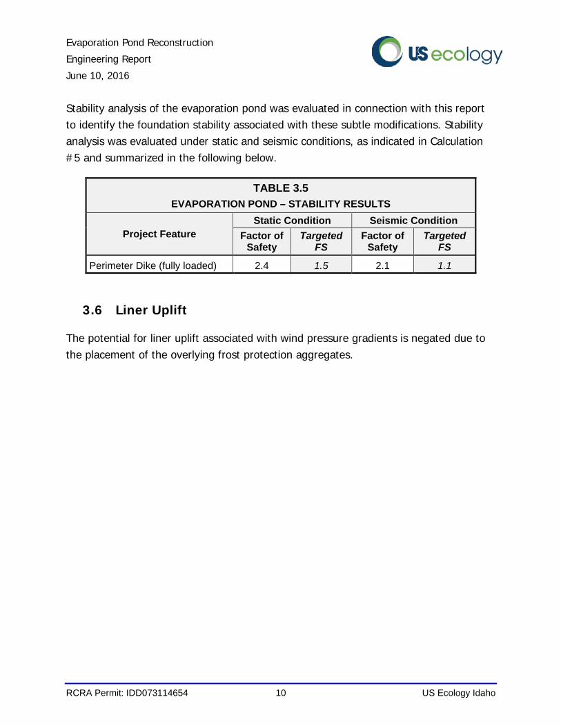
Stability analysis of the evaporation pond was evaluated in connection with this report to identify the foundation stability associated with these subtle modifications. Stability analysis was evaluated under static and seismic conditions, as indicated in Calculation #5 and summarized in the following below.
3.6 Liner Uplift
The potential for liner uplift associated with wind pressure gradients is negated due to the placement of the overlying frost protection aggregates.
TABLE 3.5
EVAPORATION POND – STABILITY RESULTS
Project Feature
Static Condition Seismic Condition
Factor of Safety
Targeted FS
Factor of Safety
Targeted FS
Perimeter Dike (fully loaded) 2.4 1.5 2.1 1.1
Evaporation Pond Reconstruction
Engineering Report
June 10, 2016
RCRA Permit: IDD073114654 11 US Ecology Idaho
4.0 ACTION LEAKAGE RATE (ALR)
The Action Leakage Rate for the evaporation pond is governed by the flow capacity of the LDCRS geocomposite, the length of the LDCRS header pipe and the flow width around the perimeter of the LDCRS sump.
Regulations outlined in 40 CFR §264.222.(a) indicate the maximum fluid head on the bottom liner must be limited to 12 inches. ALR analysis contained in Calculation #3 is based upon a more conservative assumption that the liquid head will be limited to the potential flow depth of the geocomposite layer (less than 1 inch). The ALR analysis also includes consideration for potential long-term performance reductions plus an overall factor of safety.
The footprint of the reconstructed evaporation pond will be 2.23 acres with a computed ALR of 1,700 gal/acre/day or 3,790 gal/day (2.6 gpm) for the unit.
LDCRS Pump
The LDCRS pump capacity must exceed the Action Leakage Rate. The LDCRS pump should be rated with a minimum capacity of 5 gpm when operating against a total head of 40 feet. Pump operation should be conducted in accordance with Attachment 17 of the USEI Site Permit.
Evaporation Pond Reconstruction
Engineering Report
June 10, 2016
RCRA Permit: IDD073114654 12 US Ecology Idaho
5.0 FROST PROTECTON AGGREGATES
5.1 Climate
Local climate data is available from the US Weather Service (WRCC, 2015). The average monthly temperature ranges from 76°F in August to 30°F in January. The average annual snowfall is 4.6 inches.
5.2 Frost Protection
The compacted clay liner (CCL) must be protected against the potential damaging effects of frost penetration. Similar CCL preventive measures at the site were previously analyzed in connection with the design of landfill unit Cell 15 (WGI, 2002), wherein it was determined the thickness of earthen materials would need to be in place to protect against potential frost penetration for a given critical season.
Similar frost protection preventive measures will be adopted for the reconstructed evaporation pond, as follows:
• At least 12 inches of frost protection aggregates (Cover Sand) must be in place over the CCL liner prior to October 29th; and
• At least 30 inches of frost protection aggregates (Cover Sand, and Cover Gravel or Riprap) must be in place over the CCL liner prior to January 1st.
The location and thickness of the frost protection aggregates are illustrated in Section A, Drawing EP-16-02.
5.3 Riprap Aggregates
Due to potential effects of wave action, riprap aggregate is needed to armor the frost protection material placed along the side walls. The National Resources Conservation Service design methodology for slope protection of dams and lakeshores (NRCS, 1997) was used to develop riprap parameters for the side walls of the reconstructed evaporation pond. Riprap material requirements and particle gradation were determined in Calculation #4 and included in the Construction Quality Assurance Plan (Appendix C).
Evaporation Pond Reconstruction
Engineering Report
June 10, 2016
RCRA Permit: IDD073114654 13 US Ecology Idaho
6.0 OPERATION AND CLOSURE
6.1 Waste Acceptance
The Evaporation Pond is currently permitted to manage the RCRA wastes as outlined in Condition V.A and Attachment 17 of the USEI Site Permit.
6.2 Inspection Schedule
The evaporation pond LDCRS will continue to be routinely inspected in accordance with Attachment 4 of the USEI Site Permit.
6.3 Operating Limits
A permanent depth marker will need to be installed, which will be used to identify the liquid elevation within the evaporation pond. The depth marker may consist of an HDPE pipe or some other fixed object that is placed along the sidewall of the evaporation pond and is marked with 1-foot vertical increments.
The liquid level within the reconstructed evaporation pond must be maintained within the operational capacity (at or below elevation 2570.5 feet). In the event that liquid levels exceeds elevation 2570.5 ft then the excess liquids shall be removed from the pond until the prescribed freeboard limits are achieved.
6.4 Response Actions and Repairs
Response actions and subsequent repairs related to the reconstructed evaporation pond should continue in conformance with Attachment 17 of the USEI Site Permit.
6.5 Closure
Closure requirements for the reconstructed evaporation pond are outlined in Attachment 9 of the USEI Site Permit.
Evaporation Pond Reconstruction
Engineering Report
June 10, 2016
RCRA Permit: IDD073114654 14 US Ecology Idaho
7.0 CONCLUSIONS
The proposed reconstruction of the evaporation pond will bring the pond into conformance with the current RCRA design standards. The reconstructed evaporation pond will remain within the footprint of the existing evaporation pond. The operational capacity of the pond will decrease slightly due to the inclusion of frost protection materials and minor grade line adjustments.
The frost protection aggregates will provide protection against potential frost penetration into the underlying clay liner. The evaporation pond will be operated in a manner that is capable of containing the 25-year, 24-hour storm event, with an additional 2 feet of freeboard, at all times. The evaporation pond will also maintain sufficient freeboard to contain the 100-year, 24-hour storm event, without threat of overtopping.
Evaporation Pond Reconstruction
Engineering Report
June 10, 2016
RCRA Permit: IDD073114654 15 US Ecology Idaho
8.0 REFERENCES
The following works were referenced and researched in the development of opinions and conclusions stated in this report addendum:
American Geotechnics, (2012) Landfill Engineering Report, Cell 16 Subcells 16-1 & 16-2, Grand View Facility. Boise, ID. February 8, 2012.
Federal Register, (2015). “Title 40: Protection of Environment.” Volume 25. Code of Federal Regulations. US Environmental Protection Agency. Washington, D.C.
Koerner, R.M., (2012). Designing with Geosynthetics, Sixth Edition. Xlibris Corporation. Bloomington, IN.
National Engineering Handbook (NHE), (2005) – Plastic Pipe Design. 210-VI-NEH, First Edition.
National Oceanic and Atmospheric Administration, (1973). Western U.S. Precipitation Frequency Maps - Atlas 2. 1973. URL: http://www.wrcc.dri.edu/pcpnfreq.html
Natural Resource Conversation Service (NRCS), (1997). Slope Protection for Dams and Lakeshores – Minnesota Technical Note 2. US Department of Agriculture. St. Paul, Minnesota.
Plastics Pipe Institute (PPI), (2012) PPI Handbook of Polyethylene Pipe. 2nd Edition. www.plasticpipe.org
Qian, X., Koerner, R.M., Gray, D., (2002). Geotechnical Aspects of Landfill Design and Construction. Prentice Hall. Upper Saddle River, NJ.
US Ecology Idaho (USEI), (2011). USEI Hazardous Waste Treatment, Storage, and Disposal Permit (IDD073114654). Grand View, Idaho. 2011.
US Environmental Protection Agency, (2003). Guide for Industrial Waste Management. EPA/530/R/03/001. Office of Solid Waste and Emergency Response. Washington DC. February.
US Environmental Protection Agency, (1989). Requirements for Hazardous Waste Landfill Design, Construction, and Closure. Seminar Publication. EPA/625/4-89/022.
Evaporation Pond Reconstruction
Engineering Report
June 10, 2016
RCRA Permit: IDD073114654 16 US Ecology Idaho
Center for Environmental Research Information, Office of Research and Development. Cincinnati, OH. August.
Washington Group International (WGI), (2002). Class 3 Permit Modification – Cell 15 Design, Construction, Operation, Monitoring and Closure Requirements. Boise, Idaho. December.
Western Regional Climate Center (WRCC), (2015). Accessed December 2, 2015 website. URL: http://www.wrcc.dri.edu/htmlfiles/id/id.avg.html
Natural Resource Conversation Service (NRCS), (1997). Slope Protection for Dams and Lakeshores. US Department of Agriculture Technical Note 2 St. Paul, Minnesota.
Evaporation Pond Reconstruction
Engineering Report
RCRA Permit: IDD073114654 US Ecology Idaho
Appendix A Drawings (Sealed February 4, 2016)
EP-16-00 Drawing Index / Cover Sheet
EP-16-01 Pond Plan View
EP-16-02 Pond Liner / Sections and Details
EP-16-03 Sump and Riser / Sections and Details
2/4/16
2/4/16
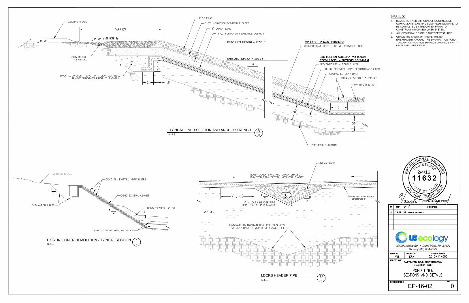
2/4/16
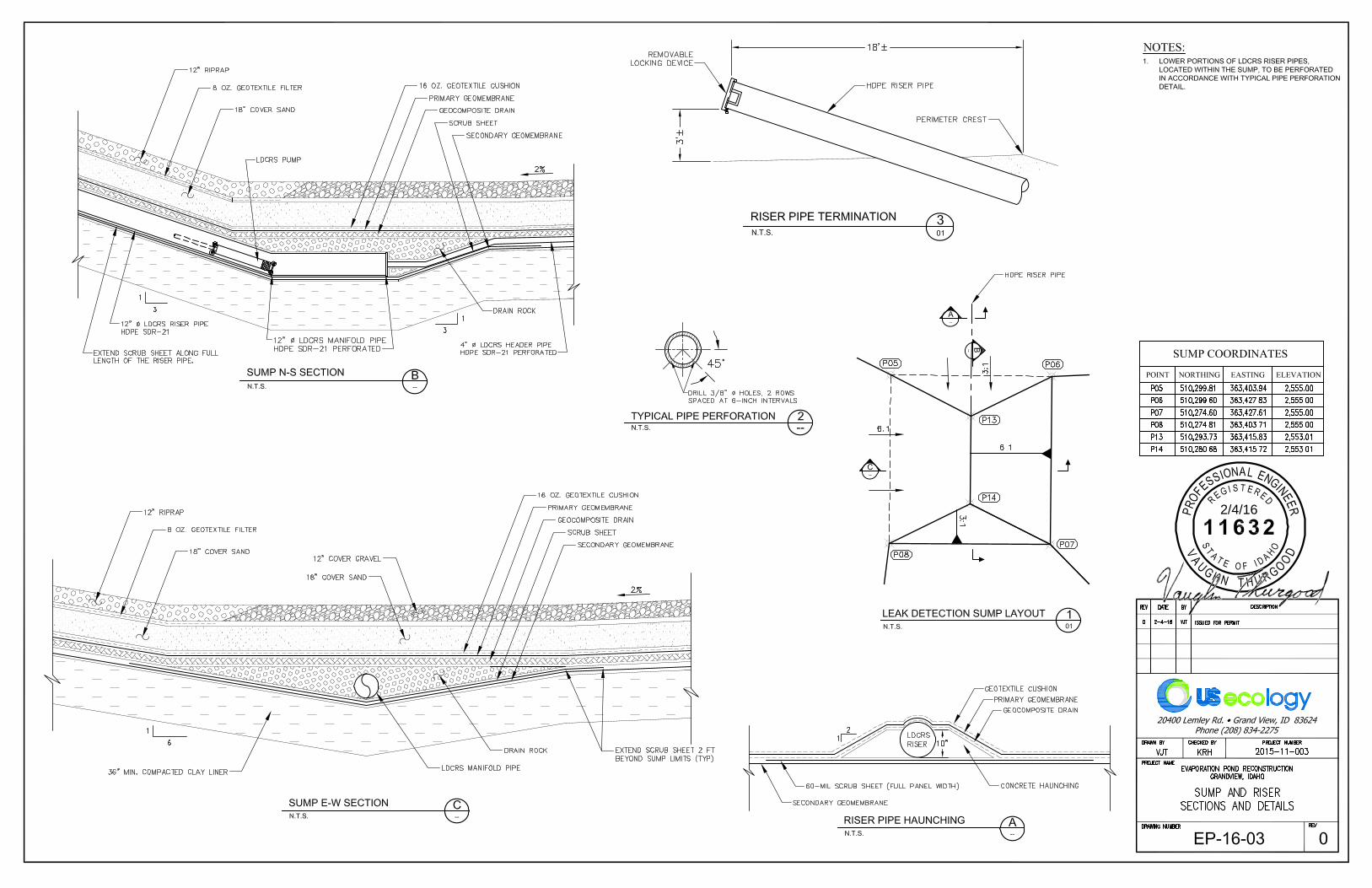
2/4/16
Evaporation Pond Reconstruction
Engineering Report
RCRA Permit: IDD073114654 US Ecology Idaho
Appendix B Calculations
Evaporation Pond Reconstruction
Engineering Report
RCRA Permit: IDD073114654 US Ecology Idaho
Calculation #1
Pond Sizing and Capacities
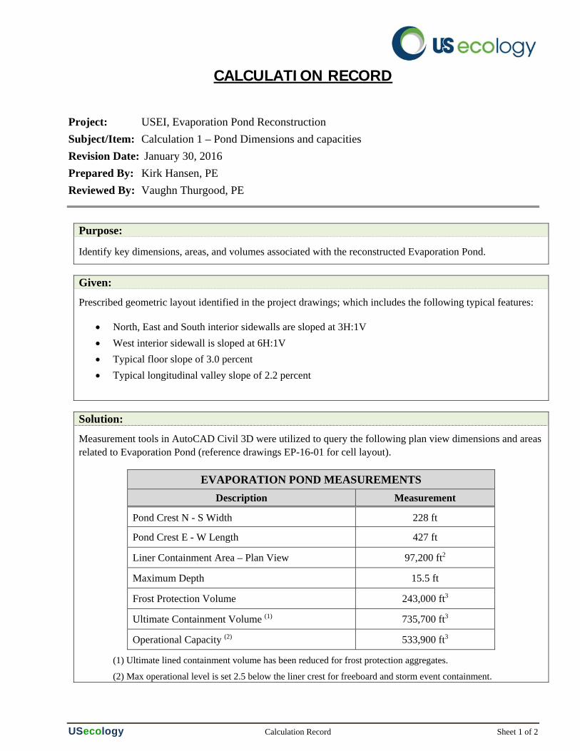
CALCULATION RECORD
Project: USEI, Evaporation Pond Reconstruction Subject/Item: Calculation 1 – Pond Dimensions and capacities Revision Date: January 30, 2016 Prepared By: Kirk Hansen, PE Reviewed By: Vaughn Thurgood, PE
USecology Calculation Record Sheet 1 of 2
Purpose:
Identify key dimensions, areas, and volumes associated with the reconstructed Evaporation Pond.
Given:
Prescribed geometric layout identified in the project drawings; which includes the following typical features:
North, East and South interior sidewalls are sloped at 3H:1V West interior sidewall is sloped at 6H:1V Typical floor slope of 3.0 percent Typical longitudinal valley slope of 2.2 percent
Solution:
Measurement tools in AutoCAD Civil 3D were utilized to query the following plan view dimensions and areas related to Evaporation Pond (reference drawings EP-16-01 for cell layout).
EVAPORATION POND MEASUREMENTS
Description Measurement
Pond Crest N - S Width 228 ft
Pond Crest E - W Length 427 ft
Liner Containment Area – Plan View 97,200 ft2
Maximum Depth 15.5 ft
Frost Protection Volume 243,000 ft3
Ultimate Containment Volume (1) 735,700 ft3
Operational Capacity (2) 533,900 ft3
(1) Ultimate lined containment volume has been reduced for frost protection aggregates.
(2) Max operational level is set 2.5 below the liner crest for freeboard and storm event containment.
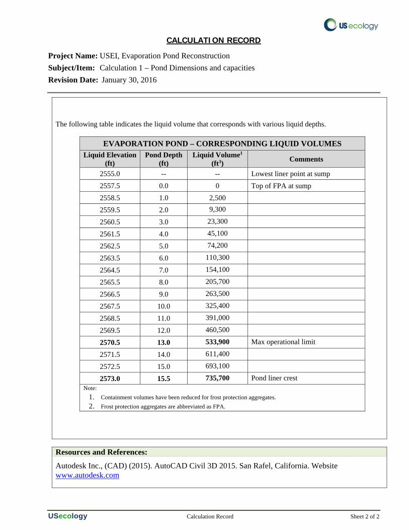
CALCULATION RECORD
Project Name: USEI, Evaporation Pond Reconstruction Subject/Item: Calculation 1 – Pond Dimensions and capacities Revision Date: January 30, 2016
USecology Calculation Record Sheet 2 of 2
The following table indicates the liquid volume that corresponds with various liquid depths.
EVAPORATION POND – CORRESPONDING LIQUID VOLUMES Liquid Elevation
(ft) Pond Depth
(ft) Liquid Volume1
(ft3) Comments
2555.0 -- -- Lowest liner point at sump 2557.5 0.0 0 Top of FPA at sump 2558.5 1.0 2,500 2559.5 2.0 9,300
2560.5 3.0 23,300
2561.5 4.0 45,100
2562.5 5.0 74,200
2563.5 6.0 110,300
2564.5 7.0 154,100
2565.5 8.0 205,700
2566.5 9.0 263,500
2567.5 10.0 325,400
2568.5 11.0 391,000
2569.5 12.0 460,500
2570.5 13.0 533,900 Max operational limit
2571.5 14.0 611,400
2572.5 15.0 693,100
2573.0 15.5 735,700 Pond liner crest Note:
1. Containment volumes have been reduced for frost protection aggregates. 2. Frost protection aggregates are abbreviated as FPA.
Resources and References:
Autodesk Inc., (CAD) (2015). AutoCAD Civil 3D 2015. San Rafel, California. Website www.autodesk.com
Evaporation Pond Reconstruction
Engineering Report
RCRA Permit: IDD073114654 US Ecology Idaho
Calculation #2
Pipe Stability
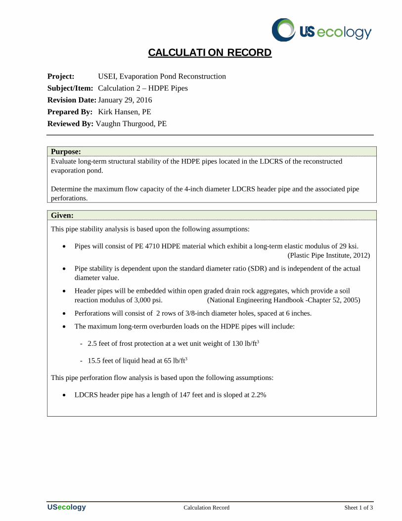
CALCULATION RECORD
Project: USEI, Evaporation Pond Reconstruction Subject/Item: Calculation 2 – HDPE Pipes Revision Date: January 29, 2016 Prepared By: Kirk Hansen, PE Reviewed By: Vaughn Thurgood, PE
USecology Calculation Record Sheet 1 of 3
Purpose: Evaluate long-term structural stability of the HDPE pipes located in the LDCRS of the reconstructed evaporation pond. Determine the maximum flow capacity of the 4-inch diameter LDCRS header pipe and the associated pipe perforations.
Given:
This pipe stability analysis is based upon the following assumptions:
• Pipes will consist of PE 4710 HDPE material which exhibit a long-term elastic modulus of 29 ksi. (Plastic Pipe Institute, 2012)
• Pipe stability is dependent upon the standard diameter ratio (SDR) and is independent of the actual diameter value.
• Header pipes will be embedded within open graded drain rock aggregates, which provide a soil reaction modulus of 3,000 psi. (National Engineering Handbook -Chapter 52, 2005)
• Perforations will consist of 2 rows of 3/8-inch diameter holes, spaced at 6 inches.
• The maximum long-term overburden loads on the HDPE pipes will include:
- 2.5 feet of frost protection at a wet unit weight of 130 lb/ft3
- 15.5 feet of liquid head at 65 lb/ft3
This pipe perforation flow analysis is based upon the following assumptions:
• LDCRS header pipe has a length of 147 feet and is sloped at 2.2%
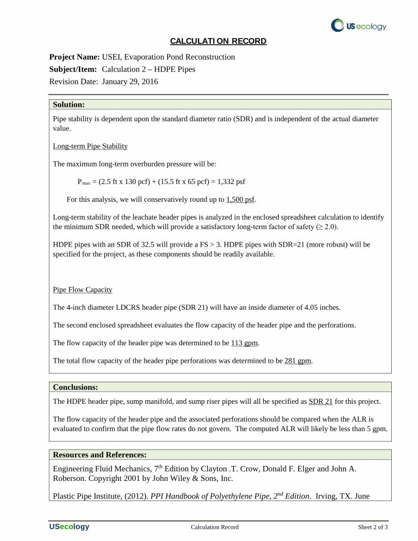
CALCULATION RECORD
Project Name: USEI, Evaporation Pond Reconstruction Subject/Item: Calculation 2 – HDPE Pipes Revision Date: January 29, 2016
USecology Calculation Record Sheet 2 of 3
Solution: Pipe stability is dependent upon the standard diameter ratio (SDR) and is independent of the actual diameter value.
Long-term Pipe Stability
The maximum long-term overburden pressure will be:
Pmax = (2.5 ft x 130 pcf) + (15.5 ft x 65 pcf) = 1,332 psf
For this analysis, we will conservatively round up to 1,500 psf.
Long-term stability of the leachate header pipes is analyzed in the enclosed spreadsheet calculation to identify the minimum SDR needed, which will provide a satisfactory long-term factor of safety (≥ 2.0).
HDPE pipes with an SDR of 32.5 will provide a FS > 3. HDPE pipes with SDR=21 (more robust) will be specified for the project, as these components should be readily available.
Pipe Flow Capacity
The 4-inch diameter LDCRS header pipe (SDR 21) will have an inside diameter of 4.05 inches.
The second enclosed spreadsheet evaluates the flow capacity of the header pipe and the perforations.
The flow capacity of the header pipe was determined to be 113 gpm.
The total flow capacity of the header pipe perforations was determined to be 281 gpm.
Conclusions:
The HDPE header pipe, sump manifold, and sump riser pipes will all be specified as SDR 21 for this project.
The flow capacity of the header pipe and the associated perforations should be compared when the ALR is evaluated to confirm that the pipe flow rates do not govern. The computed ALR will likely be less than 5 gpm.
Resources and References:
Engineering Fluid Mechanics, 7th Edition by Clayton .T. Crow, Donald F. Elger and John A. Roberson. Copyright 2001 by John Wiley & Sons, Inc.
Plastic Pipe Institute, (2012). PPI Handbook of Polyethylene Pipe, 2nd Edition. Irving, TX. June
CALCULATION RECORD
Project Name: USEI, Evaporation Pond Reconstruction Subject/Item: Calculation 2 – HDPE Pipes Revision Date: January 29, 2016
USecology Calculation Record Sheet 3 of 3
2012
U.S. Environmental Protection Agency, (EPA) (1989). Requirements for Hazardous Waste Landfill design, Construction, and Closure. Office of Research and Development Cincinnati, OH 1989.
WL Plastics Corp, (WLPC) (2011). IPS Pipe Sizes & Pressure Ratings. Web site www.wlplastics.com accessed December, 2014.
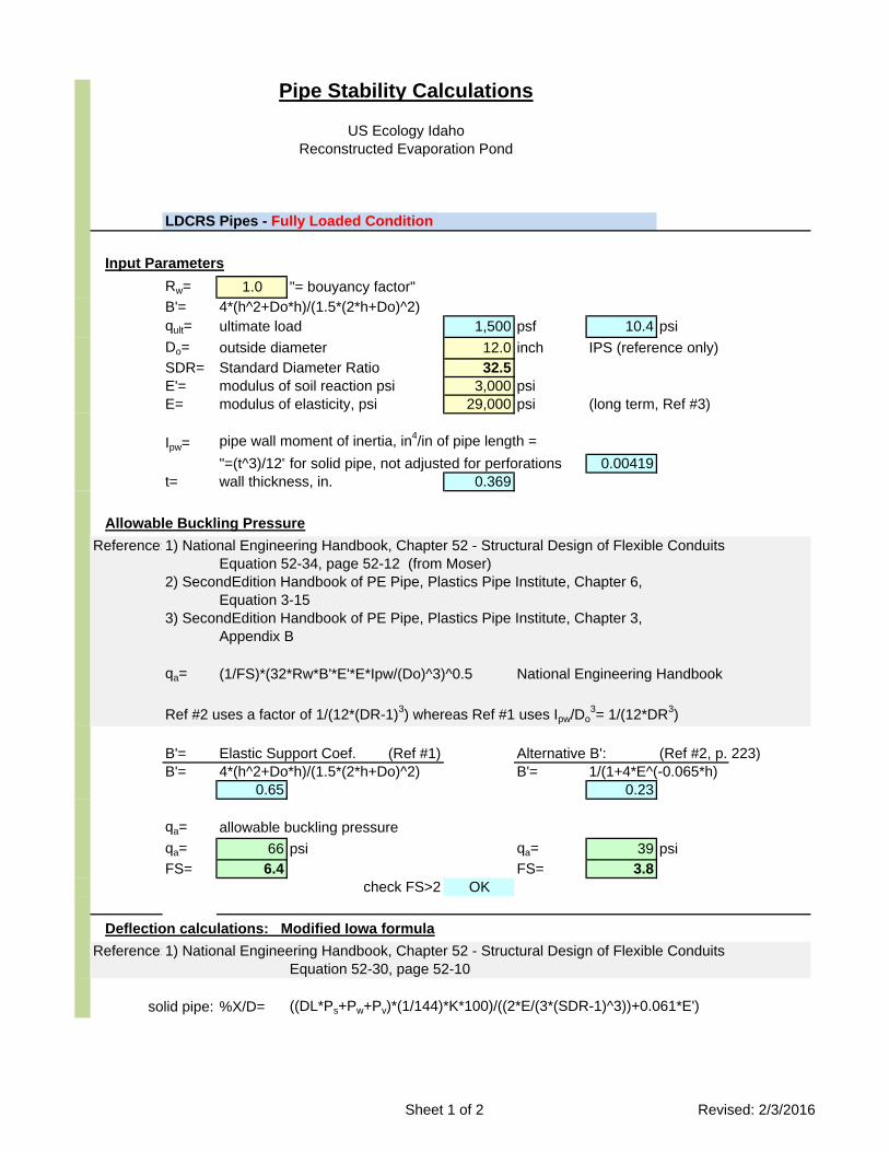
Pipe Stability Calculations
US Ecology Idaho
Reconstructed Evaporation Pond
LDCRS Pipes - Fully Loaded Condition
Input Parameters
Rw= 1.0 "= bouyancy factor"
B'= 4*(h^2+Do*h)/(1.5*(2*h+Do)^2)
qult= ultimate load 1,500 psf 10.4 psi
Do= outside diameter 12.0 inch IPS (reference only)
SDR= Standard Diameter Ratio 32.5
E'= modulus of soil reaction psi 3,000 psi
E= modulus of elasticity, psi 29,000 psi (long term, Ref #3)
Ipw= pipe wall moment of inertia, in4/in of pipe length =
"=(t^3)/12" for solid pipe, not adjusted for perforations 0.00419
t= wall thickness, in. 0.369
Allowable Buckling Pressure
Reference:1) National Engineering Handbook, Chapter 52 - Structural Design of Flexible Conduits
Equation 52-34, page 52-12 (from Moser)
2) SecondEdition Handbook of PE Pipe, Plastics Pipe Institute, Chapter 6,
Equation 3-15
3) SecondEdition Handbook of PE Pipe, Plastics Pipe Institute, Chapter 3,
Appendix B
qa= (1/FS)*(32*Rw*B'*E'*E*Ipw/(Do)^3)^0.5 National Engineering Handbook
Ref #2 uses a factor of 1/(12*(DR-1)3) whereas Ref #1 uses Ipw/Do
3= 1/(12*DR
3)
B'= Elastic Support Coef. (Ref #1) Alternative B': (Ref #2, p. 223)
B'= 4*(h^2+Do*h)/(1.5*(2*h+Do)^2) B'= 1/(1+4*E^(-0.065*h)
0.65 0.23
qa= allowable buckling pressure
qa= 66 psi qa= 39 psi
FS= 6.4 FS= 3.8
check FS>2 OK
Deflection calculations: Modified Iowa formula
Reference:1) National Engineering Handbook, Chapter 52 - Structural Design of Flexible Conduits
Equation 52-30, page 52-10
solid pipe: %X/D= ((DL*Ps+Pw+Pv)*(1/144)*K*100)/((2*E/(3*(SDR-1)^3))+0.061*E')
Sheet 1 of 2 Revised: 2/3/2016
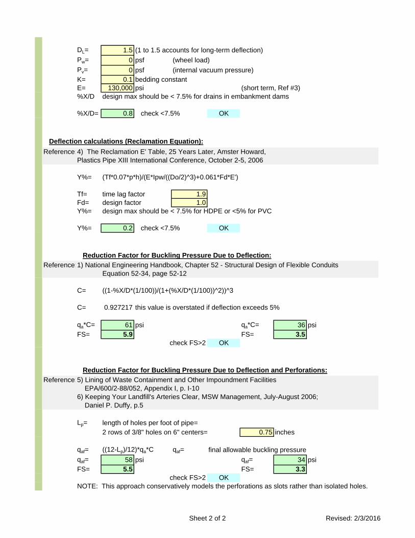
DL= 1.5 (1 to 1.5 accounts for long-term deflection)
Pw= 0 psf (wheel load)
Pv= 0 psf (internal vacuum pressure)
K= 0.1 bedding constant
E= 130,000 psi (short term, Ref #3)
%X/D design max should be < 7.5% for drains in embankment dams
%X/D= 0.8 check <7.5% OK
Deflection calculations (Reclamation Equation):
Reference:4) The Reclamation E' Table, 25 Years Later, Amster Howard,
Plastics Pipe XIII International Conference, October 2-5, 2006
Y%= (Tf*0.07*p*h)/(E*Ipw/((Do/2)^3)+0.061*Fd*E')
Tf= time lag factor 1.9
Fd= design factor 1.0
Y%= design max should be < 7.5% for HDPE or <5% for PVC
Y%= 0.2 check <7.5% OK
Reduction Factor for Buckling Pressure Due to Deflection:
Reference:1) National Engineering Handbook, Chapter 52 - Structural Design of Flexible Conduits
Equation 52-34, page 52-12
C= ((1-%X/D*(1/100))/(1+(%X/D*(1/100))^2))^3
C= 0.927217 this value is overstated if deflection exceeds 5%
qa*C= 61 psi qa*C= 36 psi
FS= 5.9 FS= 3.5
check FS>2 OK
Reduction Factor for Buckling Pressure Due to Deflection and Perforations:
Reference:5) Lining of Waste Containment and Other Impoundment Facilities
EPA/600/2-88/052, Appendix I, p. I-10
6) Keeping Your Landfill's Arteries Clear, MSW Management, July-August 2006;
Daniel P. Duffy, p.5
Lp= length of holes per foot of pipe=
2 rows of 3/8" holes on 6" centers= 0.75 inches
qaf= ((12-Lp)/12)*qa*C qaf= final allowable buckling pressure
qaf= 58 psi qaf= 34 psi
FS= 5.5 FS= 3.3
check FS>2 OK
NOTE: This approach conservatively models the perforations as slots rather than isolated holes.
Sheet 2 of 2 Revised: 2/3/2016
Evaporation Pond Reconstruction
Engineering Report
RCRA Permit: IDD073114654 US Ecology Idaho
Calculation #3
LDCRS Geocomposite and ALR
CALCULATION RECORD
Project: USEI, Reconstructed Evaporation Pond
Subject/Item: Calculation 3 – Geocomposite & Action Leakage Rate
Revision Date: February 2, 2016
Prepared By: Kirk Hansen, PE
Reviewed By: Vaughn Thurgood, PE
USecology Calculation Record Sheet 1 of 3
Purpose:
Based on a given geocomposite, determine the action leakage rate (ALR) for the leak detection system (LDCRS) as required by 40 CFR 264.222.
Compare the computed ALR against the pipe flow capacity and the LDCRS pump capacity to confirm those components do not govern.
Given:
The ALR analysis is based upon the following assumptions:
Minimum floor slope of 3.0 percent.
North, east and south side slopes are 3H:1V and the west side slope is a 6H:1V
The critical hydraulic LDCRS flow path consists of 35 feet along the east slope (3H:1V), coupled with 265 feet across the floor (3.0 percent) to the sump crest as shown in the figure below.
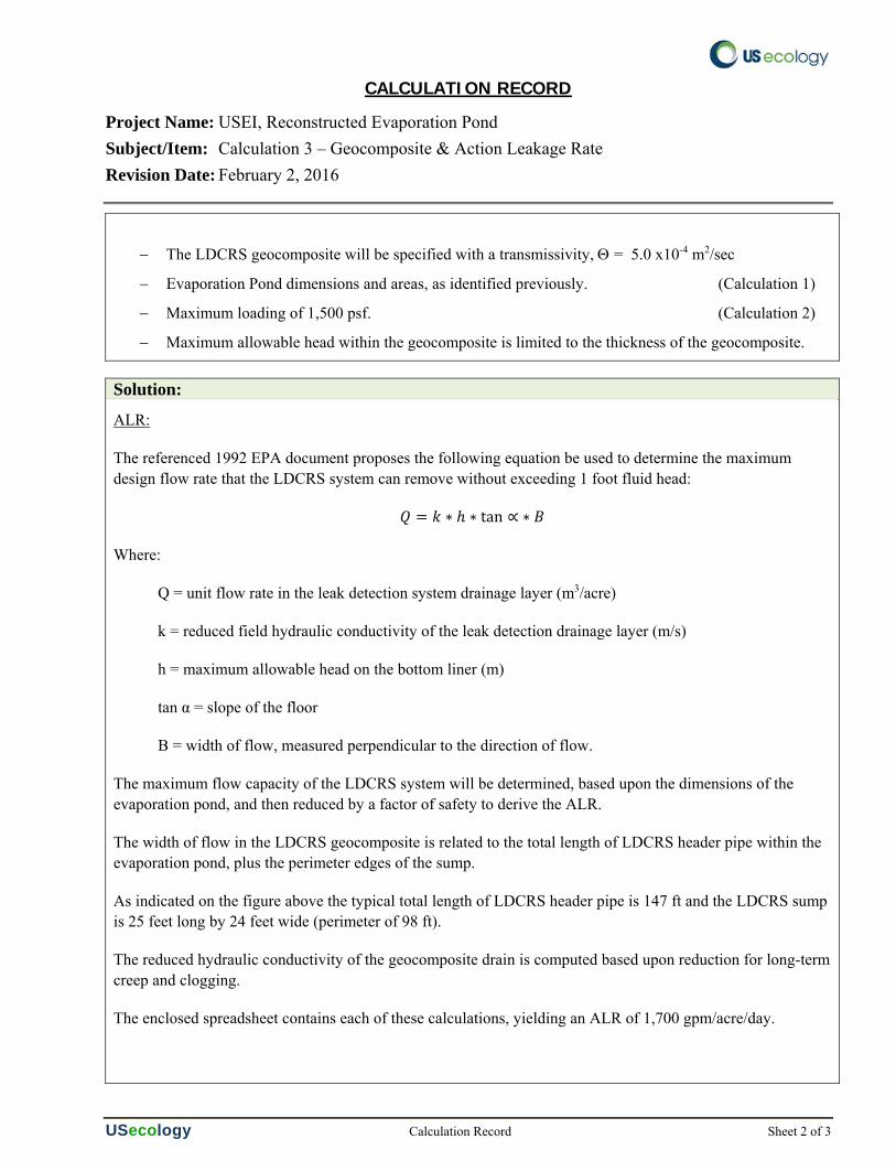
CALCULATION RECORD
Project Name: USEI, Reconstructed Evaporation Pond
Subject/Item: Calculation 3 – Geocomposite & Action Leakage Rate
Revision Date: February 2, 2016
USecology Calculation Record Sheet 2 of 3
The LDCRS geocomposite will be specified with a transmissivity, = 5.0 x10⁻⁴ m2/sec
Evaporation Pond dimensions and areas, as identified previously. (Calculation 1)
Maximum loading of 1,500 psf. (Calculation 2)
Maximum allowable head within the geocomposite is limited to the thickness of the geocomposite.
Solution:
ALR:
The referenced 1992 EPA document proposes the following equation be used to determine the maximum design flow rate that the LDCRS system can remove without exceeding 1 foot fluid head:
∗ ∗ tan ∝ ∗
Where:
Q = unit flow rate in the leak detection system drainage layer (m3/acre)
k = reduced field hydraulic conductivity of the leak detection drainage layer (m/s)
h = maximum allowable head on the bottom liner (m)
tan α = slope of the floor
B = width of flow, measured perpendicular to the direction of flow.
The maximum flow capacity of the LDCRS system will be determined, based upon the dimensions of the evaporation pond, and then reduced by a factor of safety to derive the ALR.
The width of flow in the LDCRS geocomposite is related to the total length of LDCRS header pipe within the evaporation pond, plus the perimeter edges of the sump.
As indicated on the figure above the typical total length of LDCRS header pipe is 147 ft and the LDCRS sump is 25 feet long by 24 feet wide (perimeter of 98 ft).
The reduced hydraulic conductivity of the geocomposite drain is computed based upon reduction for long-term creep and clogging.
The enclosed spreadsheet contains each of these calculations, yielding an ALR of 1,700 gpm/acre/day.
CALCULATION RECORD
Project Name: USEI, Reconstructed Evaporation Pond
Subject/Item: Calculation 3 – Geocomposite & Action Leakage Rate
Revision Date: February 2, 2016
USecology Calculation Record Sheet 3 of 3
Conclusions:
If the evaporation pond is reconstructed with an LDCRS geocomposite that exhibits a transmissivity rate of 5.0x10⁻⁴ m2/s, the LDCRS system will provide a long-term Action Leakage Rate of 1,700 gal/acre/day (2.6 gpm) for the pond unit.
The flow capacity of the LDCRS pump is specified at 5 gpm and the flow capacity of the LDCRS header pipe is a full magnitude greater. Therefore, these components will not govern the ALR considerations.
Resources and References:
US Ecology, Inc, (USEI) (2011). Notification of Class 3 Permit Modification - Landfill Cell 16 Design, Construction, Operation, Monitoring and Closure Requirements. Boise, ID October 13, 2011.
U.S. Environmental Protection Agency, (EPA) (1992). Liners and Leak Detection Systems for Hazardous Waste Land Disposal Units. Federal Register Vol. 57, No. 19 Wednesday, January 29, 1992 Rules and Regulations, D.C. 1992.
US Environmental Protection Agency, (1992). Action Leakage Rates for Leak Detection Systems. Publication EPA 530-R-92-004. Office of Solid Waste. Washington, DC.
U.S. Environmental Protection Agency, (EPA) (1989). Requirements for Hazardous Waste Landfill design, Construction, and Closure. Office of Research and Development Cincinnati, OH 1989.
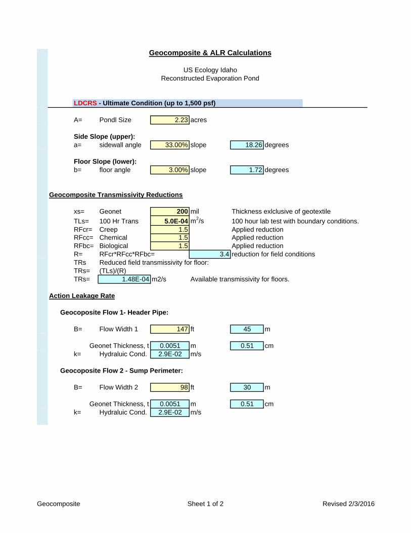
Geocomposite & ALR Calculations
US Ecology Idaho
Reconstructed Evaporation Pond
LDCRS - Ultimate Condition (up to 1,500 psf)
A= Pondl Size 2.23 acres
Side Slope (upper):
a= sidewall angle 33.00% slope 18.26 degrees
Floor Slope (lower):
b= floor angle 3.00% slope 1.72 degrees
Geocomposite Transmissivity Reductions
xs= Geonet 200 mil Thickness exlclusive of geotextile
TLs= 100 Hr Trans 5.0E-04 m2/s 100 hour lab test with boundary conditions.
RFcr= Creep 1.5 Applied reduction
RFcc= Chemical 1.5 Applied reduction
RFbc= Biological 1.5 Applied reduction
R= RFcr*RFcc*RFbc= 3.4 reduction for field conditions
TRs Reduced field transmissivity for floor:
TRs= (TLs)/(R)
TRs= 1.48E-04 m2/s Available transmissivity for floors.
Action Leakage Rate
Geocoposite Flow 1- Header Pipe:
B= Flow Width 1 147 ft 45 m
Geonet Thickness, t 0.0051 m 0.51 cm
k= Hydraluic Cond. 2.9E-02 m/s
Geocoposite Flow 2 - Sump Perimeter:
B= Flow Width 2 98 ft 30 m
Geonet Thickness, t 0.0051 m 0.51 cm
k= Hydraluic Cond. 2.9E-02 m/s
Geocomposite Sheet 1 of 2 Revised 2/3/2016
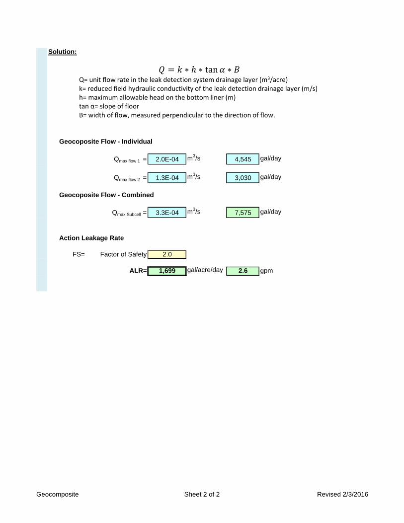
Solution:
Geocoposite Flow - Individual
Qmax flow 1 = 2.0E-04 m3/s 4,545 gal/day
Qmax flow 2 = 1.3E-04 m3/s 3,030 gal/day
Geocoposite Flow - Combined
Qmax Subcell = 3.3E-04 m3/s 7,575 gal/day
Action Leakage Rate
FS= Factor of Safety 2.0
ALR= 1,699 gal/acre/day 2.6 gpm
∗ ∗ tan ∗Q= unit flow rate in the leak detection system drainage layer (m3/acre)k= reduced field hydraulic conductivity of the leak detection drainage layer (m/s)h= maximum allowable head on the bottom liner (m)tan α= slope of floorB= width of flow, measured perpendicular to the direction of flow.
Geocomposite Sheet 2 of 2 Revised 2/3/2016

Evaporation Pond Reconstruction
Engineering Report
RCRA Permit: IDD073114654 US Ecology Idaho
Calculation #4
Wave Height
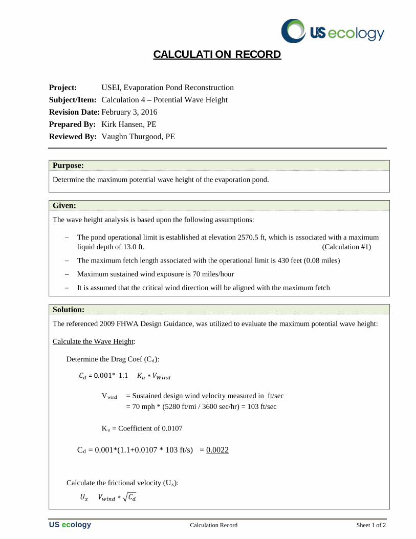
CALCULATION RECORD
Project: USEI, Evaporation Pond Reconstruction Subject/Item: Calculation 4 – Potential Wave Height Revision Date: February 3, 2016 Prepared By: Kirk Hansen, PE Reviewed By: Vaughn Thurgood, PE
US ecology Calculation Record Sheet 1 of 2
Purpose:
Determine the maximum potential wave height of the evaporation pond.
Given:
The wave height analysis is based upon the following assumptions:
− The pond operational limit is established at elevation 2570.5 ft, which is associated with a maximum liquid depth of 13.0 ft. (Calculation #1)
− The maximum fetch length associated with the operational limit is 430 feet (0.08 miles)
− Maximum sustained wind exposure is 70 miles/hour
− It is assumed that the critical wind direction will be aligned with the maximum fetch
Solution: The referenced 2009 FHWA Design Guidance, was utilized to evaluate the maximum potential wave height:
Calculate the Wave Height:
Determine the Drag Coef (Cd):
Vwind = Sustained design wind velocity measured in ft/sec = 70 mph * (5280 ft/mi / 3600 sec/hr) = 103 ft/sec Ku = Coefficient of 0.0107 Cd = 0.001*(1.1+0.0107 * 103 ft/s) = 0.0022 Calculate the frictional velocity (Ux):
𝐶𝐶𝑑𝑑 = 0.001*(1.1 + 𝐾𝐾𝑢𝑢 ∗ 𝑉𝑉𝑊𝑊𝑊𝑊𝑊𝑊𝑑𝑑)
𝑈𝑈𝑥𝑥 = 𝑉𝑉𝑤𝑤𝑊𝑊𝑊𝑊𝑑𝑑 ∗ �𝐶𝐶𝑑𝑑
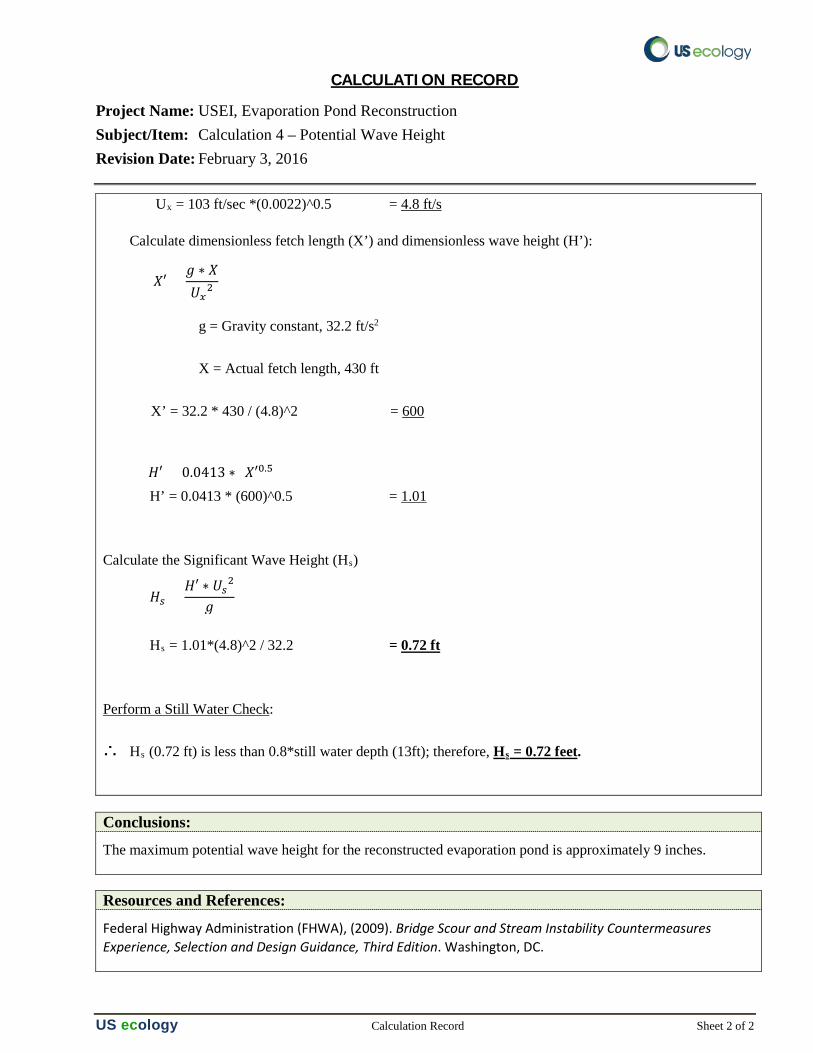
CALCULATION RECORD
Project Name: USEI, Evaporation Pond Reconstruction Subject/Item: Calculation 4 – Potential Wave Height Revision Date: February 3, 2016
US ecology Calculation Record Sheet 2 of 2
Ux = 103 ft/sec *(0.0022)^0.5 = 4.8 ft/s
Calculate dimensionless fetch length (X’) and dimensionless wave height (H’): g = Gravity constant, 32.2 ft/s2 X = Actual fetch length, 430 ft X’ = 32.2 * 430 / (4.8)^2 = 600 H’ = 0.0413 * (600)^0.5 = 1.01 Calculate the Significant Wave Height (Hs) Hs = 1.01*(4.8)^2 / 32.2 = 0.72 ft Perform a Still Water Check: ∴ Hs (0.72 ft) is less than 0.8*still water depth (13ft); therefore, Hs = 0.72 feet.
Conclusions:
The maximum potential wave height for the reconstructed evaporation pond is approximately 9 inches.
Resources and References:
Federal Highway Administration (FHWA), (2009). Bridge Scour and Stream Instability Countermeasures Experience, Selection and Design Guidance, Third Edition. Washington, DC.
𝑋𝑋′ =𝑔𝑔 ∗ 𝑋𝑋𝑈𝑈𝑥𝑥2
𝐻𝐻′ = 0.0413 ∗ (𝑋𝑋′0.5)
𝐻𝐻𝑠𝑠 =𝐻𝐻′ ∗ 𝑈𝑈𝑠𝑠2
𝑔𝑔

Evaporation Pond Reconstruction
Engineering Report
RCRA Permit: IDD073114654 US Ecology Idaho
Calculation #5
Foundation Stability
CALCULATION RECORD
Project: USEI, Evaporation Pond Reconstruction Subject/Item: Calculation 5 – Stability Calculation Revision Date: February 3, 2016 Prepared By: Kirk Hansen, PE Reviewed By: Vaughn Thurgood, PE
USecology Calculation Record Sheet 1 of 2
Purpose:
Evaluate the foundation stability of the reconstructed evaporation pond with the slight geometric modifications.
Confirm that the perimeter dike materials and pond foundation materials will provide adequate long term stability
Given:
The existing dikes have been in place for more than 30 years. During pond reconstruction minor geometric changes will occur, as illustrated in Drawing EP-16-02 and described below; however, the majority of the existing foundation materials will remain unaltered. The stability of the existing perimeter dike and foundation materials were previously evaluated by Geosystems Consultants in 1998 (Appendix D.4.8 of the USEI site permit). The foundation and perimeter dike materials have exhibited consistent stability over the past 30 plus years of service.
The dimensions of the exterior dike slope was modeled as:
• exterior dike slope 2H:1V (unchanged)
• crest height of 24 feet (reduced slightly)
• crest width of 40 feet (increased slightly)
• maximum interior slope 3H:1V (unchanged)
• a maximum potential liquid loading of 1,300 psf will be included as a surcharge load.
The pond perimeter dike and foundation materials consist of granular sand and gravel aggregates with the following properties:
• Unit weight, γ = 120 lb/ft3
• Non-cohesive, c = 0
• Internal friction, ɸ = 34 degrees
CALCULATION RECORD
Project Name: USEI, Evaporation Pond Reconstruction Subject/Item: Calculation 5 – Stability Calculation Revision Date: February 3, 2016
USecology Calculation Record Sheet 2 of 2
Potential seismic load at the site includes a peak ground acceleration of 0.051g. (AGEO,2012)
Solution: Stability Model
For this analysis, Slope W software was utilized to compute the slope stability for the typical cross section.
The model analyzed dike failure using radial failures (Grid Radius Circular failure envelopes). Mohr-Coulomb shear strength envelopes were used. Static and seismic loading conditions were both analyzed to identify critical failure surfaces that could potentially impact the integrity of the liner system.
Conclusions:
The results of the enclosed SlopeW analysis are summarized in the table below.
The foundation of the reconstructed evaporation pond will continue to exhibit excellent stability.
EVAPORATION POND – DIKE STABILITY RESULTS
Loading Scenario Factor of Safety Targeted FS
1. Static - Critical Condition 2.4 1.5
2. Seismic - Critical Condition 2.1 1.1
Resources and References: American Geotechnics, (2012) Landfill Engineering Report, Cell 16 Subcells 16-1 & 16-2, Grand View Facility. Boise, ID. February 8, 2012.
Geo-Slope International, (SlopeW) (2012). GeoStudio 2012 Slope W by GEO-SLOPE International Calgery, Albert, Canada web site: http://www.geo-slope.com Version 8.14.1.10087.
US Ecology Idaho (USEI), (2011). USEI Hazardous Waste Treatment, Storage, and Disposal Permit (IDD073114654). Grand View, Idaho. 2011.
U.S. Geological Survey (USGS) (2014) U.S. Seismic Design Maps, by the US Department of Interior USGS website at http://earthquake.usgs.gov/designmaps/us/application.php.
Evaporation Pond Reconstruction
Engineering Report
RCRA Permit: IDD073114654 US Ecology Idaho
Stability Analysis - Static Condition
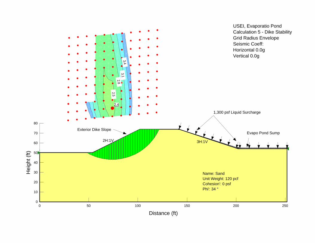
2.5
2.8
3.1
3
.4
2.4
2H:1V 3H:1V
1,300 psf Liquid Surcharge
Evapo Pond Sump
Name: Sand
Unit Weight: 120 pcf
Cohesion': 0 psf
Phi': 34 °
Exterior Dike Slope
USEI, Evaporatio Pond Calculation 5 - Dike Stability Grid Radius Envelope Seismic Coeff:
Horizontal 0.0g
Vertical 0.0g
Distance (ft)
0 50 100 150 200 250
He
igh
t (f
t)
0
10
20
30
40
50
60
70
80
Evaporation Pond Reconstruction
Engineering Report
RCRA Permit: IDD073114654 US Ecology Idaho
Stability Analysis - Seismic Condition
2.2
2.5
2.8
3
.1
3
.4
2.1
2H:1V 3H:1V
1,300 psf Liquid Surcharge
Evapo Pond Sump
Name: Sand
Unit Weight: 120 pcf
Cohesion': 0 psf
Phi': 34 °
Exterior Dike Slope
USEI, Evaporatio Pond Calculation 5 - Dike Stability Grid Radius Envelope Seismic Coeff:
Horizontal 0.051 g
Vertical 0.051 g
Distance (ft)
0 50 100 150 200 250
He
igh
t (f
t)
0
10
20
30
40
50
60
70
80
Evaporation Pond Reconstruction
Engineering Report
RCRA Permit: IDD073114654 US Ecology Idaho
Appendix C Construction Quality Assurance (CQA) Plan
US ecology 20400 Lemley Road Grand View, ID 83624 (208) 834-2275
Construction Quality Assurance Plan
Evaporation Pond Reconstruction
US Ecology Idaho PO Box 400
Grand View, Idaho
RCRA Permit No. IDD073114654
June 10, 2016 (Revision 1)
Prepared by:
___________________________ ___________________________ Kirk Hansen, PE Vaughn Thurgood, PE Civil Engineer Civil Engineer
Kirk Robert Hansen
6-10-2016
Construction Quality Assurance Plan
Evaporation Pond Reconstruction
June 10, 2016
US ecology 20400 Lemley Road • Grand View, ID 83624 • (208) 834-2275
TABLE OF CONTENTS
PAGE
1.0 INTRODUCTION ................................................................................. 1
2.0 CONSTRUCTION QUALITY ASSURANCE TEAM ................................... 2
2.1 FACILITY OWNER ........................................................................................... 2 2.2 DESIGN ENGINEER .......................................................................................... 2 2.3 CQA MANAGER ............................................................................................. 2 2.4 CQA TECHNICIAN .......................................................................................... 4 2.5 SURVEYOR ................................................................................................... 5 2.6 CONSTRUCTION CONTRACTOR ............................................................................ 5 2.7 GEOMEMBRANE/GEOSYNTHETIC INSTALLER ............................................................ 5 2.8 QC MATERIALS TESTING ENTITY ........................................................................ 6 2.9 QA GEOSYNTHETICS TESTING............................................................................ 6 2.10 CQA JUDGMENT SAMPLING ............................................................................... 6 2.11 CQA STAFFING ............................................................................................. 7
3.0 CONSTRUCTION QUALITY ASSURANCE MEETINGS ........................... 9
3.1 PRE-CONSTRUCTION MEETING ........................................................................... 9 3.2 PROGRESS MEETINGS .................................................................................... 10 3.3 PROBLEM/CONSTRUCTION DEFICIENCY MEETINGS ................................................. 10
4.0 EARTHWORK MATERIALS ................................................................ 12
4.1 PREPARED SUBGRADE AND COMMON FILL ................................................. 12 4.2 SUBGRADE QUALITY CONTROL DOCUMENTATION ................................................... 13 4.3 SUBGRADE FINAL GRADES/TOLERANCE ............................................................... 14 4.4 DRAIN ROCK AGGREGATES .............................................................................. 14
5.0 COMPACTED CLAY LINER ................................................................. 15
5.1 CLAY BORROW SOURCE ................................................................................. 15 5.2 PRE-CONSTRUCTION TEST PAD ........................................................................ 16 5.3 COMPACTED CLAY SUBGRADE PREPARATION ........................................................ 16 5.4 COMPACTED CLAY PLACEMENT ......................................................................... 16 5.5 COMPACTED CLAY TESTING REQUIREMENTS ......................................................... 18 5.6 COMPACTED CLAY NON-CONFORMING TESTS ....................................................... 19 5.7 COMPACTED CLAY FINISHED SURFACE ................................................................ 20 5.8 COMPACTED CLAY SURVEY CONTROL ................................................................. 21 5.9 COMPACTED CLAY CQA DOCUMENTATION ........................................................... 21
6.0 GEOMEMBRANES .............................................................................. 22
6.1 GEOMEMBRANE MATERIAL SPECIFICATIONS ......................................................... 22 6.2 MATERIAL HANDLING AND SUBMITTALS .............................................................. 24
Construction Quality Assurance Plan
Evaporation Pond Reconstruction
June 10, 2016
US ecology 20400 Lemley Road • Grand View, ID 83624 • (208) 834-2275
6.3 GEOMEMBRANE SUBGRADE CONDITION ............................................................... 25 6.4 GEOMEMBRANE PANEL PLACEMENT .................................................................... 25 6.5 GEOMEMBRANE TRIAL SEAMS .......................................................................... 27 6.6 GEOMEMBRANE PANEL SEAMING ....................................................................... 28 6.7 GEOMEMBRANE SEAM TESTING ........................................................................ 30 6.8 GEOMEMBRANE NON-CONFORMING TESTS ........................................................... 32 6.9 GEOMEMBRANE REPAIRS ................................................................................ 32 6.10 GEOMEMBRANE CQA DOCUMENTATION .............................................................. 33
7.0 GEOSYNTHETICS .............................................................................. 34
7.1 GEOSYNTHETICS MATERIAL SPECIFICATIONS ........................................................ 34 7.2 GEOSYNTHETICS MANUFACTURER QUALITY CONTROL AND CONFORMANCE TESTING ........ 36 7.3 GENERAL GEOSYNTHETIC INSTALLATION ............................................................. 36 7.4 GEOSYNTHETICS PANEL SEAMING/TYING ............................................................ 37 7.5 GEOSYNTHETICS REPAIRS ............................................................................... 38 7.6 GEOSYNTHETICS CQA DOCUMENTATION ............................................................. 38
8.0 DRAIN PIPE COMPONENTS .............................................................. 39
8.1 PIPING MATERIAL SPECIFICATIONS .................................................................... 39 8.2 PIPING MANUFACTURER QUALITY CONTROL ......................................................... 40 8.3 PIPING INSTALLATION ................................................................................... 40 8.4 PIPING SURVEY CONTROL ............................................................................... 40 8.5 PIPING CQA DOCUMENTATION ........................................................................ 41
9.0 FROST PROTECTION AGGREGATES .................................................. 42
9.1 FROST PROTECTION MATERIAL REQUIREMENTS .................................................... 42 9.2 FROST PROTECTION PLACEMENT RESTRICTIONS .................................................... 43 9.3 FROST PROTECTION TESTING REQUIREMENTS ...................................................... 44 9.4 FROST PROTECTIVE COVER CQA DOCUMENTATION ................................................ 44
10.0 CQA REPORT DOCUMENTATION ...................................................... 45
10.1 GENERAL ................................................................................................... 45 10.2 CQA FIELD REPORTS .................................................................................... 45 10.3 AS-BUILT RECORD DRAWINGS ......................................................................... 45 10.4 FINAL CERTIFICATION ................................................................................... 46
11.0 REFERENCES .................................................................................... 48
Construction Quality Assurance Plan
Evaporation Pond Reconstruction
June 10, 2016
US ecology 1
1.0 INTRODUCTION
This Construction Quality Assurance (CQA) Plan was developed to define construction procedures and material acceptance criteria for the reconstructed Evaporation Pond at the USEI Facility in Grand View, Idaho.
This plan also outlines the requirements for the subsequent CQA Certification Report. This CQA Plan will be implemented continually during project construction. CQA inspection, sampling, testing and reporting will be performed for the following design components:
• Prepare Subgrade • Compacted clay layer • Geomembrane layers • Geocomposite drainage layer • Frost protection aggregates • Geotextile layers • HDPE pipe components • Drainage aggregates
Construction Quality Assurance Plan
Evaporation Pond Reconstruction
June 10, 2016
US ecology 2
2.0 CONSTRUCTION QUALITY ASSURANCE TEAM
A brief description of key positions, their minimum qualifications (as appropriate), and their roles in the construction activities is included in this section.
2.1 Facility Owner
US Ecology Idaho (USEI) is the owner and permittee of the facility. USEI is responsible for oversight of the construction activities at the facility and the coordination of regulatory activities pertaining to the facility. USEI may designate a project manager and/or a project engineer to coordinate construction activities associated with US Ecology Idaho Evaporation Pond.
2.2 Design Engineer
The Design Engineer’s primary responsibility is to design a facility that fulfills the operational requirements of the Owner/Operator, complies with accepted design practices, and meets or exceeds the minimum requirements of the IDEQ. The Design Engineer may be an employee of US Ecology Idaho or a design consultant hired by US Ecology Idaho. If unexpected conditions are encountered during construction, the Design Engineer may be involved with changes to some aspect of the design during the construction phase of the project.
2.3 CQA Manager
The CQA Manager shall be a Licensed Idaho Professional Engineer with experience in civil or geotechnical engineering and project management. The CQA Manager must be an independent consultant (not a US Ecology employee). The CQA Manager has overall responsibility for execution of this CQA Plan and final certification of the constructed product.
Other CQA Manager responsibilities include education and supervision of CQA Inspectors, ensuring that testing laboratories are conforming to CQA requirements, ensuring that sample chain-of-custody procedures are followed, confirming that test data are accurately reported and that test data are maintained for later reporting, and preparation of periodic reports. The CQA Manager will verify that communication of all
Construction Quality Assurance Plan
Evaporation Pond Reconstruction
June 10, 2016
US ecology 3
QA/QC issues are communicated to and acted upon by the appropriate organizations. The CQA Manager will oversee the CQA Inspectors and may perform duties associated with a CQA Inspector. The most important duty of the CQA manager is overall responsibility for confirming that the facility was constructed in accord with the IDEQ-approved material requirements and the project drawings.
Key responsibilities of the CQA Manager, which may be delegated to a CQA Inspector, include:
1. Reviewing the CQA Plan and the project Drawings so that the plan may be implemented without contradictions or discrepancies;
2. Review all contractor submittals for completeness and conformance with the project plans. Acceptance, necessary clarifications, or rejection shall be communicated back to the Contractor in a timely manner.
3. Review QC tests that are performed by the Contractor.
4. Conduct independent QA tests as outlined within this plan.
5. Complete daily and weekly field reports that will document the chronological history of the project components.
6. Confirm that testing equipment, personnel and procedures do not change during the project or that any such changes do not result in a deterioration of the monitoring process.
7. Verify that the minimum contract requirements and Contractor’s proposed and accepted quality control measures are being followed.
8. Verify that the equipment used in testing meets the test requirements and that the tests are conducted by qualified personnel according to the standard procedures defined within this plan.
9. Observation, QA testing and documentation of the activities related to construction quality assurance during the installation of the various materials, soil and geosynthetics associated with the project;
Construction Quality Assurance Plan
Evaporation Pond Reconstruction
June 10, 2016
US ecology 4
10. Report to the Contractor results of all observations and tests as the work progresses and interact with the Contractor to provide assistance in modifying the materials and work scope to comply with the specified design.
11. Acceptance or rejection of work items.
12. Verify that all deficient areas have been reworked and re-tested to meet the material acceptance criteria.
13. Prepare a final CQA Report. The purpose of the CQA Report is to provide a permanent record of the construction to the reviewing regulatory agencies that the liner system and earthwork components were constructed in accordance with the Engineering Report, Project Drawings, this CQA Plan, and applicable regulations;
14. Scheduling, coordinating, and reviewing all CQA activities as required by permit documents and supplemental information; and
15. Preparation of the CQA Certification Report.
2.4 CQA Technician
CQA technician(s) under the direct supervision of the CQA Manager, will provide full-time inspection of construction activities. CQA technicians will have at least an associate's degree in engineering or a minimum of 3 years of related construction experience. CQA technicians will function independent of the construction Contractor and will be employed by the same firm as the CQA Manager, or by a firm retained by the CQA Manager or Owner.
Each CQA Inspector will maintain a field logbook in which key activities and observations will be recorded on a daily basis. In addition, a daily field report or log will be prepared at the completion of each day to serve as a formalized quality assurance record regarding the field construction activities, testing, and communications that occurred that day. The CQA Manager or Inspectors will document the conversations with and test results provided by the Contractor.
Construction Quality Assurance Plan
Evaporation Pond Reconstruction
June 10, 2016
US ecology 5
The CQA Inspectors have the authority to conduct all observations, testing, and documentation as necessary to satisfy the requirements of this plan. The CQA Inspectors will collect and tabulate all field inspection and test information and will perform audits of QC activities performed by contractors. CQA Inspectors will report their findings and recommendations to the CQA Manager.
2.5 Surveyor
The Surveyor shall be an Idaho Registered Professional Land Surveyor and demonstrate experience in providing surveying services for similar types of construction and shall be retained by the Owner or the CQA Manager. The Surveyor is responsible for certification that the liners were constructed to the lines, grades and thickness specified on the project drawings.
2.6 Construction Contractor
The construction Contractor is responsible for constructing the evaporation pond in accordance with the approved plans. The construction Contractor has the responsibility for coordinating construction activities including hiring construction personnel, scheduling construction activities, purchasing construction materials, coordinating subcontractors, and other construction coordination activities.
The construction Contractor is required to perform quality control (QC) testing as outlined in this CQA Plan. All test requirements listed within this plan are considered to be QC tests unless they are specifically identified as QA tests (which will be coordinated by the CQA Manager). The construction Contractor is responsible for informing the owner and the CQA personnel of the scheduling and occurrence of all construction activities. USEI may utilize its own employees to perform or coordinate construction activities.
2.7 Geomembrane/Geosynthetic Installer
The geosynthetic installer is responsible for the handling, storing, placing, seaming, temporary loading and other aspects of the geosynthetic material installation as described in this CQA plan and the applicable Engineering Report. The geosynthetic installer is also responsible for submitting all quality control certificates to the CQA
Construction Quality Assurance Plan
Evaporation Pond Reconstruction
June 10, 2016
US ecology 6
Manager including but not limited to those from the resin supplier(s) and the geomembrane/geosynthetic manufacturer(s). The geosynthetic installer shall have experience in installing at least 2,000,000 ft2 of similar geomembrane/geosynthetics.
2.8 QC Materials Testing Entity
A testing laboratory, independent of the construction Contractor, will be retained by the Contractor to perform QC field and laboratory testing on construction materials (i.e. soils and aggregate) as identified in the CQA Plan. The construction materials testing laboratory is responsible for ensuring that the tests are performed in accordance with applicable methods and standards, for following internal testing procedures, for maintaining sample chain-of-custody records, and for reporting test results to the Contractor and the CQA Manager.
The QC testing entity must be willing to allow the CQA Manager to observe the sample preparation and testing procedures and record keeping procedures, if they so desire. The CQA Manager may request that they be allowed to observe some or all tests on a particular job at any time. The testing personnel must be willing to accommodate such a request, but the observer should not interfere with the testing or slow the testing process.
2.9 QA Geosynthetics Testing
The CQA Manager shall retain a qualified geosynthetics testing laboratory not affiliated with the manufacturer, fabricator, or installer to perform QA laboratory testing on geosynthetic materials as identified in the CQA Plan. The independent geosynthetics laboratory is responsible for ensuring that the tests are performed in accordance with applicable methods and standards, for following internal testing procedures, for maintaining sample chain-of-custody records, and for reporting test results to the CQA Manager.
2.10 CQA Judgment Sampling
It is neither possible nor economically feasible to perform one hundred percent inspection of many materials and construction processes; thus, the quality of the material or process must be estimated from the results of inspection of a representative
Construction Quality Assurance Plan
Evaporation Pond Reconstruction
June 10, 2016
US ecology 7
sample of the total material or constructed facility. Examples of this situation include estimations of the integrity of geomembrane field seams by destructive testing and assessments of the characteristics of the soil portion of a composite liner.
Judgment sampling refers to any sampling procedure in which decisions concerning sample size, sample selection scheme, and sample locations are based on considerations not derived from probability theory. The objective of such sampling may be to test typical samples that represent the whole, to test zones of suspect quality, or a combination of the two. For example, in sampling field-constructed geomembrane seams, samples could be taken at a minimum frequency per unit length of seam at locations assigned by the Construction Quality Assurance (CQA) Inspector before seaming is started. Additional samples could then be taken from locations of suspect quality. The success of judgment sampling is dependent on the knowledge, capability, and experience of the CQA personnel. Organizations that construct a large number of similar projects often employ judgment sampling using sample frequencies based on past construction experience. For example, more intensive sampling may be justified in areas where acceptance criteria may be more difficult to achieve, such as clay liner construction on steep slopes.
2.11 CQA Staffing
The following recommendations are the proposed minimum staffing requirements to meet the CQA observation procedures. The terms “full-time” and “part-time” refer to the presence of the CQA personnel on the job site. The term “full-time’ should not be construed to mean that all operations of the Contractor will be individually observed, but that a CQA representative would be on the project site during working hours of a specific activity. Adequate staffing will be provided to document the performance of construction operations. The term “part-time” should not be interpreted to mean only an occasional CQA presence, but rather that an activity does not require the intense documentation and observations of a critical item. For example, part-time CQA presence would be adequate during mass excavations, while a full-time presence of CQA representatives are needed during the installation of the geomembranes. The number of required full-and part-time CQA representatives is dependent upon the degree of each activity being performed and the number of activities occurring concurrently.
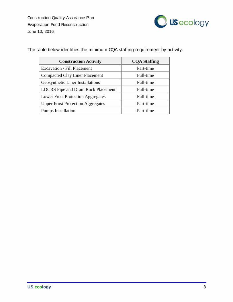
Construction Quality Assurance Plan
Evaporation Pond Reconstruction
June 10, 2016
US ecology 8
The table below identifies the minimum CQA staffing requirement by activity:
Construction Activity CQA Staffing Excavation / Fill Placement Part-time Compacted Clay Liner Placement Full-time Geosynthetic Liner Installations Full-time LDCRS Pipe and Drain Rock Placement Full-time Lower Frost Protection Aggregates Full-time Upper Frost Protection Aggregates Part-time Pumps Installation Part-time
Construction Quality Assurance Plan
Evaporation Pond Reconstruction
June 10, 2016
US ecology 9
3.0 CONSTRUCTION QUALITY ASSURANCE MEETINGS
Periodic meetings will be conducted to provide effective communication between the various organizations involved in construction at the facility. These meetings will be used to identify specific responsibilities and authority during construction. During construction, these meetings will be used to resolve construction problems and to minimize the potential for problems to develop.
Meetings will include, but will not be limited to, a pre-construction meeting, construction progress meetings, and problem/construction deficiency meetings. The CQA Manager will prepare meeting notes for each of these meetings and will circulate the notes with the participants.
A brief description of each meeting is provided in sections below.
3.1 Pre-Construction Meeting
A pre-construction meeting will be conducted prior to the start of major construction activities. At a minimum, representatives from the Owner, the CQA Manager, and the construction Contractor will attend the pre-construction meeting. The purpose of this meeting includes:
• Introducing the various organizations/individuals and identifying their authority and responsibilities;
• Establish a protocol for test observation and the communication of test results;
• Reviewing the requirements of the CQA Plan and respective expectations;
• Discuss the established protocol for handling construction deficiencies, rework and re-testing;
• Review work area security and safety protocol;
• Discuss procedures for the protection of materials and for the prevention of damage from inclement weather or other events;
• Discuss the schedule and sequencing of work;
Construction Quality Assurance Plan
Evaporation Pond Reconstruction
June 10, 2016
US ecology 10
• Review and discuss procedures for manufacturer’s quality control and construction QC procedures to be employed by manufacturers, installers and contractors;
• Make a list of action items requiring resolution and assign responsibility;
• Conduct a site walk to verify that the project plans are understood and identify suitable storage locations; and
• Discuss procedures to be followed for Request for Information from the various parties involved with the Project.
3.2 Progress Meetings
Construction progress meetings will be conducted by the CQA Manager during the construction activities. Construction progress meetings will typically be conducted on a weekly basis. Personnel attending these meetings will be identified by the CQA Manager based on the specific issues being discussed at the meeting. The objective of these meetings is to:
• Review the activities and accomplishments since the previous progress meeting;
• Maintain lines of communication, resolve problems, and identify action items; and
• Review the planned construction activities and CQA requirements for those activities.
3.3 Problem/Construction Deficiency Meetings
Problem/construction deficiency meetings will be conducted, as needed, when a potential problem or construction deficiency has been identified. CQA Manager will schedule this meeting and will identify other personnel to attend the meeting. The objective of these meetings is to:
• Identify the problem/construction deficiency;
• Discuss corrective actions for the problem/construction deficiency;
Construction Quality Assurance Plan
Evaporation Pond Reconstruction
June 10, 2016
US ecology 11
• Identify permit restrictions and/or permit modification requirements; and
• Implement corrective actions.
Construction Quality Assurance Plan
Evaporation Pond Reconstruction
June 10, 2016
US ecology 12
4.0 EARTHWORK MATERIALS
Earthwork consists of subgrade excavation and preparation, common fill placement and drain rock aggregates as identified on the project drawing. Materials placement procedures, grade tolerance and acceptance criteria for these earthwork components are outlined in this section of the CQA Plan.
The Contractor shall provide appropriate dust suppression throughout all earthwork activities.
4.1 PREPARED SUBGRADE AND COMMON FILL
The existing subgrade of the evaporation pond will be exposed after demolition and disposal of the existing pond liner components is completed. Upon exposure, the existing subgrade shall be inspected by the Engineer to confirm that the existing materials are suitable for use and identify any area of necessary over-excavation and replacement. The Contractor will not be compensated for over-excavation that occurs without prior approval of the Engineer.
The existing subgrade shall be excavated and or graded to the lines and grades outlined in the project drawings. Areas that require additional subgrade materials to meet the required grade lines shall be backfilled in a controlled manner with Common Fill aggregates, as defined herein.
PREPARED SUBGRADE
Prepared subgrade is defined as the upper 8 inches of material located immediately below the compacted clay liner system. Prepared subgrade shall not contain frozen material, debris, roots, or any significant amounts of organic material.
Prepared subgrade shall be moisture conditioned and compacted to at least 90% of standard proctor (ASTM D 698). The final surface of the prepared subgrade shall be smooth-drum rolled. The Contractor shall protect the prepared subgrade from the effects of weather until placement of the subsequent layer.
Construction Quality Assurance Plan
Evaporation Pond Reconstruction
June 10, 2016
US ecology 13
COMMON FILL
Common fill shall be obtained from on-site aggregate stockpiles or designated on-site excavations. Acceptable materials shall be free of stones greater than 6-inches, debris, roots, or any significant amount organic matter. Materials which classify as OH or OL according to ASTM D 2487 are unsuitable for use as common fill. Common fill shall not be placed while saturated or in a frozen condition.
Common fill placement shall be limited to uniform lifts with a maximum loose lift thickness of 12 inches or a compacted lift thickness of 8 inches. Common fill shall be moisture conditioned and compacted to at least 90% of standard proctor (ASTM D 698).
4.2 Subgrade Quality Control Documentation
The Contractor shall conduct quality control tests on common fill and prepared subgrade aggregates in accordance with the following table:
TABLE 4.1 – SOIL QC TESTING REQUIREMENTS
Property Test Method Frequency
Grain Size ASTM D 422 1 per 1,000 cyd or change in material
Moisture-Density Curve ASTM D698 1 per 1,000 cyd or change in material
Density Measurement ASTM D 2922 1 per 500 cyd - Common Fill
1 per 20,000 ft2 – Prepared Subgrade
Soil Classification ASTM D 2487 1 per 1,000 cyd or change in material
The Contractor shall provide a daily report to the Owner regarding earthwork activities. This document shall include the following minimum information:
1. Quantity and location of material placed and compacted 2. Results of earthwork QC testing
The Contractor shall accommodate CQA inspection of all earthwork activities and assist in obtaining additional samples for confirmation purposes, as needed.
Construction Quality Assurance Plan
Evaporation Pond Reconstruction
June 10, 2016
US ecology 14
4.3 Subgrade Final Grades/Tolerance
The Contractor shall perform grading to the required lines and grades as shown on the Drawings. The prepared subgrade shall be constructed to a tolerance of –0.50 to +0.00 feet relative to the elevations specified in the project drawings.
4.4 Drain Rock Aggregates
Drain rock aggregate will be installed within the LDCRS sump and along the header pipe.
1. Drain rock aggregate shall be sound, durable, hard, resistant to weathering, and subangular to subrounded in shape. Aggregates shall be free of any deleterious materials such as concrete, asphalt, organic matter, limestone, or other foreign matter.
2. Drain rock aggregate used in the LDCRS shall exhibit less than 35% wear when tested according to ASTM C535 (grading 3) and shall meet the gradation below unless specified otherwise approved by the Engineer.
TABLE 4.2 – DRAIN ROCK GRADATION
Sieve Size (inch) Percent Passing
1 ½ 100
½ 0-10
No. 200 Sieve 0 to 2
3. Conformance testing for drain rock aggregates will be performed under the supervision of the CQA Manager. The contractor shall assist CQA in obtaining the necessary samples.
4. CQA personnel shall verify and document that drain rock aggregates have been constructed to the lines and thickness specified in the project drawings.
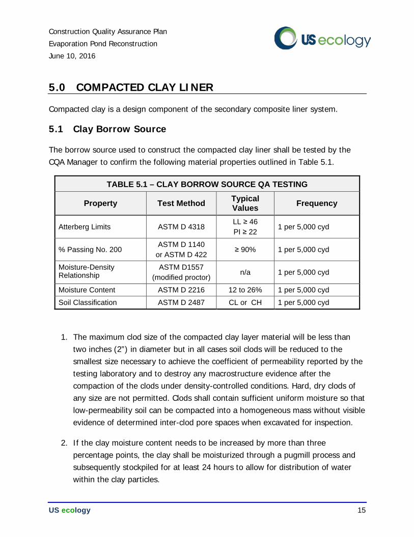
Construction Quality Assurance Plan
Evaporation Pond Reconstruction
June 10, 2016
US ecology 15
5.0 COMPACTED CLAY LINER
Compacted clay is a design component of the secondary composite liner system.
5.1 Clay Borrow Source
The borrow source used to construct the compacted clay liner shall be tested by the CQA Manager to confirm the following material properties outlined in Table 5.1.
TABLE 5.1 – CLAY BORROW SOURCE QA TESTING
Property Test Method Typical Values
Frequency
Atterberg Limits ASTM D 4318 LL ≥ 46
PI ≥ 22 1 per 5,000 cyd
% Passing No. 200 ASTM D 1140
or ASTM D 422 ≥ 90% 1 per 5,000 cyd
Moisture-Density Relationship
ASTM D1557
(modified proctor) n/a 1 per 5,000 cyd
Moisture Content ASTM D 2216 12 to 26% 1 per 5,000 cyd
Soil Classification ASTM D 2487 CL or CH 1 per 5,000 cyd
1. The maximum clod size of the compacted clay layer material will be less than two inches (2”) in diameter but in all cases soil clods will be reduced to the smallest size necessary to achieve the coefficient of permeability reported by the testing laboratory and to destroy any macrostructure evidence after the compaction of the clods under density-controlled conditions. Hard, dry clods of any size are not permitted. Clods shall contain sufficient uniform moisture so that low-permeability soil can be compacted into a homogeneous mass without visible evidence of determined inter-clod pore spaces when excavated for inspection.
2. If the clay moisture content needs to be increased by more than three percentage points, the clay shall be moisturized through a pugmill process and subsequently stockpiled for at least 24 hours to allow for distribution of water within the clay particles.
Construction Quality Assurance Plan
Evaporation Pond Reconstruction
June 10, 2016
US ecology 16
5.2 Pre-construction Test Pad
Given the relatively small footprint of the Evaporation Pond, the pond reconstruction effort will likely occur in conjunction with the periodic Cell 16 landfill development activities at the site, while the local clay borrow source is active and the clay processing plant is set-up on site. The Cell 16 clay liner specification outlines a potential test pad process (Section 3.5 of Specification 02228), which may be periodically utilized to confirm clay liner constructability and the establishment of a correlation between in-situ field permeability and laboratory permeability test results. The most recent correlation established for the Ketterling clay source indicates that the upper bound for flex-wall laboratory permeability testing (ASTM D 5084) should be 6.7x10⁻⁸ cm/sec. This acceptance criteria is referred to as the “upper bound” within this CQA Plan.
A new test pad is warranted when an alternate borrow source will be used or if the construction process is significantly altered. If an additional test pad is constructed in conjunction with the Cell 16 landfill construction effort, then the new “upper bound” should be adopted for use in constructing the Evaporation Pond clay liner component.
5.3 Compacted Clay Subgrade Preparation
1. The subgrade shall be shaped to the lines, grades and cross section as shown on the Drawings.
2. Soft or otherwise unsatisfactory material shall be removed and replaced with properly compacted satisfactory material. The subgrade shall be approved prior to the placement of compacted clay liner material.
3. Prior to compacted clay liner construction, the excavation surface shall be surveyed for documentation.
5.4 Compacted Clay Placement
1. Low-permeability soil shall be placed in uniform lifts parallel to the ground surface, including slopes, unless otherwise approved.
Construction Quality Assurance Plan
Evaporation Pond Reconstruction
June 10, 2016
US ecology 17
2. Loose lift thickness shall not exceed 9 inches. Compacted lift thickness shall not exceed 6 inches. The exception is the first lift of the compacted clay liner over the subgrade may be 12 inches compacted thickness.
3. Lifts that have been sealed with a smooth-drum compactor shall be scarified approximately 1 inch and wetted as necessary before placement of subsequent lifts of low-permeability soil.
4. Moisture adjustments of up to three percentage points can be made just prior to compaction at the final location. Material that is too wet or too dry (more than three percentage points) shall be removed from the soil layer and replaced at the Contractor’s expense.
5. A Cat 825 footed compactor (or approved equivalent) shall be used to compact the low-permeability soil. Other compaction equipment may be used if demonstrated to provide adequate compaction through the test strip construction.
6. Use of grade stakes, hubs, pins, and pin flags are prohibited on the clay liner. Survey control during construction of the clay liner should be accomplished with the aid of global satellite positioning (GPS) equipment. The surface of the compacted clay liner shall be free of all sharp objects that could puncture the succeeding geomembrane liner. Holes that are inadvertently made in the clay liner shall be filled with bentonite chips, moisturized and tamped with a rod.
7. Overlying lifts shall be placed so that the longitudinal joints between lifts are staggered by at least 2 feet. Joints between old and new lifts, successive day’s work, or joints that have become excessively dry shall be scarified, moisture conditioned, and reworked as necessary to ensure continuous bonding. Adjoining low-permeability soils shall have nearly the same moisture content.
8. The Contractor is encouraged to over-build the clay liner with a sacrificial lift of clay. The upper surface of the compacted clay liner should be left in a rough state, during the interim between construction and final trimming, to reduce the effects of interstitial wicking of moisture to the surface.
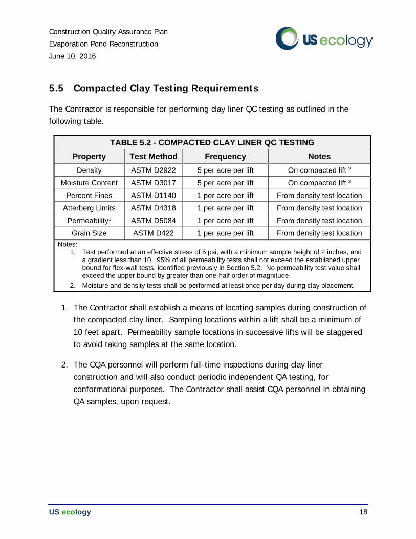
Construction Quality Assurance Plan
Evaporation Pond Reconstruction
June 10, 2016
US ecology 18
5.5 Compacted Clay Testing Requirements
The Contractor is responsible for performing clay liner QC testing as outlined in the following table.
TABLE 5.2 - COMPACTED CLAY LINER QC TESTING
Property Test Method Frequency Notes
Density ASTM D2922 5 per acre per lift On compacted lift 2
Moisture Content ASTM D3017 5 per acre per lift On compacted lift 2
Percent Fines ASTM D1140 1 per acre per lift From density test location
Atterberg Limits ASTM D4318 1 per acre per lift From density test location
Permeability1 ASTM D5084 1 per acre per lift From density test location
Grain Size ASTM D422 1 per acre per lift From density test location
Notes: 1. Test performed at an effective stress of 5 psi, with a minimum sample height of 2 inches, and
a gradient less than 10. 95% of all permeability tests shall not exceed the established upper bound for flex-wall tests, identified previously in Section 5.2. No permeability test value shall exceed the upper bound by greater than one-half order of magnitude.
2. Moisture and density tests shall be performed at least once per day during clay placement.
1. The Contractor shall establish a means of locating samples during construction of the compacted clay liner. Sampling locations within a lift shall be a minimum of 10 feet apart. Permeability sample locations in successive lifts will be staggered to avoid taking samples at the same location.
2. The CQA personnel will perform full-time inspections during clay liner construction and will also conduct periodic independent QA testing, for conformational purposes. The Contractor shall assist CQA personnel in obtaining QA samples, upon request.
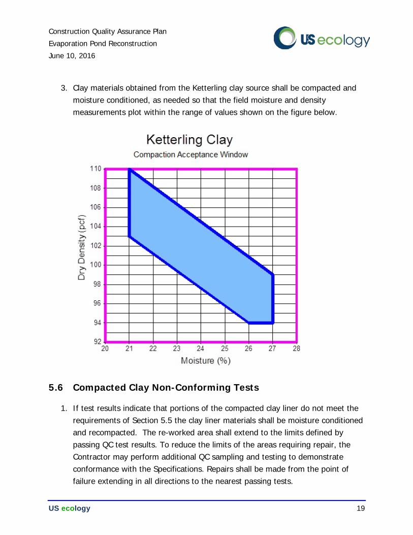
Construction Quality Assurance Plan
Evaporation Pond Reconstruction
June 10, 2016
US ecology 19
3. Clay materials obtained from the Ketterling clay source shall be compacted and moisture conditioned, as needed so that the field moisture and density measurements plot within the range of values shown on the figure below.
5.6 Compacted Clay Non-Conforming Tests
1. If test results indicate that portions of the compacted clay liner do not meet the requirements of Section 5.5 the clay liner materials shall be moisture conditioned and recompacted. The re-worked area shall extend to the limits defined by passing QC test results. To reduce the limits of the areas requiring repair, the Contractor may perform additional QC sampling and testing to demonstrate conformance with the Specifications. Repairs shall be made from the point of failure extending in all directions to the nearest passing tests.
Construction Quality Assurance Plan
Evaporation Pond Reconstruction
June 10, 2016
US ecology 20
2. Reworked areas will be tested and confirmed to demonstrate compliance. If the requirements of Section 5.5 cannot be met with additional compaction, the clay lift shall be removed and replaced with suitable clay material.
3. Spare flex-wall permeability samples may be obtained whenever a permeability sample is obtained for laboratory testing. In the event that the initial permeability test yields non-conforming results, the original result may be negated if both of the spare samples are tested and subsequently demonstrate conformance.
5.7 Compacted Clay Finished Surface
1. The final lift for compacted clay layer systems will not contain any rocks or any other materials that can cause damage to the overlying geomembrane.
2. Frozen clay material shall not be used in the construction of the compacted clay liner. If superficial freezing occurs on the surface of a clay lift, the surface shall be scarified and recompacted. Frost protection materials must be in-place in accordance with the seasonal requirements outlined in Section 9 of this CQA Plan.
3. The final surface shall be constructed with a tolerance of –0.00 to +0.50 feet from the elevations specified on the Drawings. The final surface shall not deviate more than 2 inches from a 10-foot-long straight edge placed anywhere on the finished surface.
4. The Contractor shall protect the clay liner from the effects of weather. The finished, smooth surface and moisture content of the clay liner shall be maintained by the Contractor until the Geomembrane Liner contractor inspects, approves, and deploys the geomembrane liner.
5. If, in the CQA Manager’s opinion, the compacted clay liner has been allowed to desiccate, the Contractor shall perform a moisture content test. If the moisture content of the liner has decreased by more than two percentage points, the following corrective action shall be taken as directed by the Owner:
Construction Quality Assurance Plan
Evaporation Pond Reconstruction
June 10, 2016
US ecology 21
6. If the compacted clay liner has been desiccated to a depth less than or equal to the thickness of a single lift, the Contractor shall disk, moisten, allow to uniformly rehydrate, and re-compact the lift.
7. If the clay layer has been desiccated to a depth greater than the thickness of a single lift, the Contractor shall remove the clay from the construction area, process the clay, and replace the clay accordingly. The depth of removal shall be a minimum of 3 inches below the desiccation cracking as determined by the CQA Manager.
5.8 Compacted Clay Survey Control
1. The as-built thickness of the compacted clay layer will be determined by a licensed professional land surveyor.
2. Prior to the placement of any clay materials, the as-built elevation of the prepared subgrade will be surveyed at a minimum frequency of once per 10,000 square feet. The completed clay layer will be surveyed to ensure the specified minimum thickness of compacted clay layer (36 inches) has been achieved.
5.9 Compacted Clay CQA Documentation
CQA documentation for the compacted clay liner, at a minimum, will include:
1. Test reports for field and laboratory tests performed prior to and during construction. Tests reports will include sample number, coordinate location, and results;
2. A project map which illustrates permeability sample locations and identification and the associated lift identity; and
3. An as-built survey signed and sealed by an Idaho Registered Professional Land Surveyor.
Construction Quality Assurance Plan
Evaporation Pond Reconstruction
June 10, 2016
US ecology 22
6.0 GEOMEMBRANES
Geomembrane layers comprise the composite liner system.
6.1 Geomembrane Material Specifications
1. Geomembrane material must be produced from virgin raw materials. Reground, reworked or trim materials from the same lot may be acceptable but recycled or reclaimed materials must not be used in the manufacturing process.
2. HDPE material and the associated welding rods will contain between 2% and 3% carbon black and may contain no more than 1% other additives.
3. Raw material (resin) used in the production of the geomembrane shall meet the requirements in the table below, tested at a frequency of once per 180,000 lbs.
TABLE 6.1 – HDPE RESIN PROPERTIES
Property Test Method Required Value
Density ASTM D 1505 0.934 – 0.940 g/cc
Melt Flow Index ASTM D 1238
190/2.16 ≤1.0 g/ 10 min
Oxidative Induction Time ASTM D 3895 100 min
4. Geomembrane sheet must be free from pinholes, surface blemishes, scratches, or other defects (e.g., non-uniform color, streaking, roughness, agglomerates of carbon black or other additives).
5. All geomembrane material will be shipped in rolls. Folded or creased sections of panels are not acceptable and will not be used unless they are a normal part of the manufacturing process.
6. Each roll is to be identified with labels indicating roll number, thickness, length, width and manufacturer.
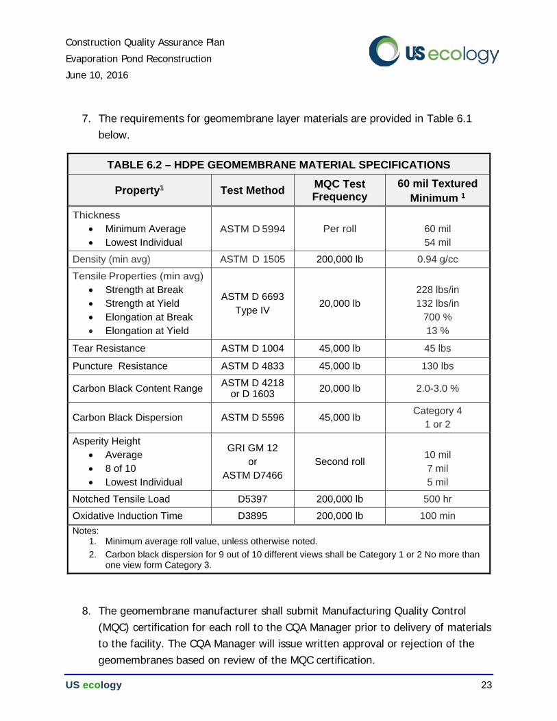
Construction Quality Assurance Plan
Evaporation Pond Reconstruction
June 10, 2016
US ecology 23
7. The requirements for geomembrane layer materials are provided in Table 6.1 below.
TABLE 6.2 – HDPE GEOMEMBRANE MATERIAL SPECIFICATIONS
Property1 Test Method MQC Test Frequency
60 mil Textured
Minimum 1
Thickness
• Minimum Average
• Lowest Individual
ASTM D 5994 Per roll
60 mil
54 mil
Density (min avg) ASTM D 1505 200,000 lb 0.94 g/cc
Tensile Properties (min avg)
• Strength at Break
• Strength at Yield
• Elongation at Break
• Elongation at Yield
ASTM D 6693
Type IV 20,000 lb
228 lbs/in
132 lbs/in
700 %
13 %
Tear Resistance ASTM D 1004 45,000 lb 45 lbs
Puncture Resistance ASTM D 4833 45,000 lb 130 lbs
Carbon Black Content Range ASTM D 4218
or D 1603 20,000 lb 2.0-3.0 %
Carbon Black Dispersion ASTM D 5596 45,000 lb Category 4
1 or 2
Asperity Height
• Average
• 8 of 10
• Lowest Individual
GRI GM 12
or
ASTM D7466
Second roll
10 mil
7 mil
5 mil
Notched Tensile Load D5397 200,000 lb 500 hr
Oxidative Induction Time D3895 200,000 lb 100 min
Notes: 1. Minimum average roll value, unless otherwise noted.
2. Carbon black dispersion for 9 out of 10 different views shall be Category 1 or 2 No more than one view form Category 3.
8. The geomembrane manufacturer shall submit Manufacturing Quality Control (MQC) certification for each roll to the CQA Manager prior to delivery of materials to the facility. The CQA Manager will issue written approval or rejection of the geomembranes based on review of the MQC certification.
Construction Quality Assurance Plan
Evaporation Pond Reconstruction
June 10, 2016
US ecology 24
9. Additional geomembrane QA samples may be obtained at the manufacturing plant or upon site delivery for confirmation testing, as needed.
10. CQA personnel will inspect the delivered materials for damage and defects. Pushing, sliding or dragging of rolls may cause material damage and must be avoided.
11. Care in accordance with the manufacturer’s recommendations shall be taken to keep the materials clean and free from damage prior to installation. If rolls are stored at the job site for more than 6 months, a sacrificial covering or temporary shelter shall be provided for protection against ultraviolet light exposure, and accidental damage.
12. The geomembrane manufacturer shall have experience in manufacturing at least 10 million square feet of similar geomembranes, while the geosynthetic material installer shall have experience installing at least 2 million square feet of similar geomembranes.
6.2 Material Handling and Submittals
1. Small supporting equipment, such as generators, operating on the geomembrane must be placed on a sacrificial surface or rub sheet in order to help protect the geomembrane.
2. All geomembrane layers that are installed as part of a composite liner system or final cover system will have continuous on-site inspection during installation by the CQA personnel.
3. All field sampling and testing, both during installation and after completion of the geomembrane layer installation, will be performed under the observation of the CQA personnel.
4. Geomembrane related submittals shall be submitted in accordance with the following schedule:
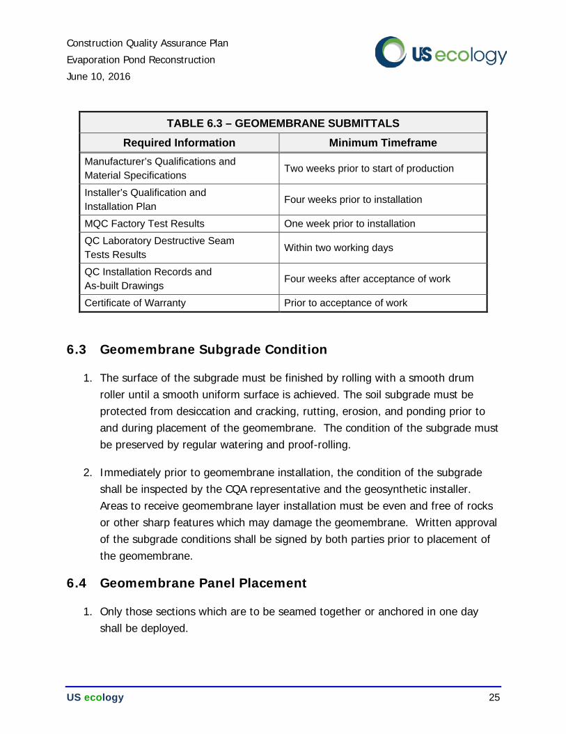
Construction Quality Assurance Plan
Evaporation Pond Reconstruction
June 10, 2016
US ecology 25
TABLE 6.3 – GEOMEMBRANE SUBMITTALS
Required Information Minimum Timeframe
Manufacturer’s Qualifications and
Material Specifications Two weeks prior to start of production
Installer’s Qualification and
Installation Plan Four weeks prior to installation
MQC Factory Test Results One week prior to installation
QC Laboratory Destructive Seam
Tests Results Within two working days
QC Installation Records and
As-built Drawings Four weeks after acceptance of work
Certificate of Warranty Prior to acceptance of work
6.3 Geomembrane Subgrade Condition
1. The surface of the subgrade must be finished by rolling with a smooth drum roller until a smooth uniform surface is achieved. The soil subgrade must be protected from desiccation and cracking, rutting, erosion, and ponding prior to and during placement of the geomembrane. The condition of the subgrade must be preserved by regular watering and proof-rolling.
2. Immediately prior to geomembrane installation, the condition of the subgrade shall be inspected by the CQA representative and the geosynthetic installer. Areas to receive geomembrane layer installation must be even and free of rocks or other sharp features which may damage the geomembrane. Written approval of the subgrade conditions shall be signed by both parties prior to placement of the geomembrane.
6.4 Geomembrane Panel Placement
1. Only those sections which are to be seamed together or anchored in one day shall be deployed.
Construction Quality Assurance Plan
Evaporation Pond Reconstruction
June 10, 2016
US ecology 26
2. The geomembrane should not be placed during inclement weather such as rain, high winds or freezing temperatures, and shall not be installed in areas of ponded water.
3. Personnel working on the geomembrane will not smoke, wear damaging shoes, or engage in any other activity likely to damage the geomembrane.
4. No vehicular traffic will be allowed on the geomembrane prior to placement of the protective cover, cover topsoil or drainage layers. Only low-ground pressure equipment (e.g. ATVs or other small rubber tired equipment with a ground pressure less than 5 psi and a total weight of less than 750 pounds) may be allowed to traverse directly over the geomembrane.
5. At the time of installation, the Contractor shall give each deployed panel an identification number.
6. The panel layout shall minimize the number and length of field seams. The liner sheets shall be oriented in a manner that reduces stress on the seams. To this end, the liner shall be placed with seams oriented downslope where practicable. Horizontal seams shall be located at least 10 feet from the toe of the slope or areas of potential stress concentrations.
7. Panels will be positioned with the overlap recommended by the manufacturer, but not less than 3 inches (3"). The edge of the upslope sheet will be positioned above the edge of the downslope sheet.
8. The method of panel deployment shall not cause scratches or crimps in the geomembrane and should not damage the subgrade. The method shall also follow the manufacturer’s recommendation(s) to minimize wrinkles, especially differential wrinkles between adjacent panels.
9. The geomembrane installer shall provide adequate temporary ballast, as needed, to prevent uplift by wind.
10. If a liner section experiences damage during installation, the liner shall be replaced or repaired by the installer to the satisfaction of the CQA Manager.
Construction Quality Assurance Plan
Evaporation Pond Reconstruction
June 10, 2016
US ecology 27
11. Direct contact with the geomembrane shall be minimized. Scrub sheets shall be used under mechanical equipment and placed in high pedestrian traffic areas.
12. Cutting of patches shall be performed off the liner surface.
13. After panel deployment, the installer shall follow the manufacturer’s recommendations for minimizing wrinkles. Each panel shall be allowed to adjust to for ambient air temperature prior to field seaming.
14. Each panel shall be inspected to insure that the geomembrane is free from holes, blisters, foreign matter, tears, punctures, or any other anomalies. All damaged geomembranes will be repaired as directed by the CQA Manager or the CQA Technician.
6.5 Geomembrane Trial Seams
1. Testing of trial seams will be conducted by the geosynthetic installer under observation by the CQA personnel. The geosynthetic installer will maintain and use equipment and personnel at the site to test the trial seams.
2. A trial seam will be made for each seaming apparatus to be used in field seaming. If more than one seaming technician uses the same apparatus, a separate trial seam will be made for each apparatus/technician combination that will perform field welding. Trial seams will be made each day prior to production welding. These seams will be made on excess pieces of geomembrane liner to verify that seaming conditions are adequate. Date, time, material type, machine temperature, seaming apparatus ID, and seamer initials will be recorded for each trial seam.
3. Trial seams will be made at the beginning of each seaming period, such as morning start-up and after mid-day lunch break or at least once every 5 hours for each seamer and seaming apparatus used during the day. Trial seams shall also be made for each occurrence of significantly different conditions such as temperature change, humidity, dust, or any time the machine is turned off for more than 30 minutes. Additional trial seams may be required at the request of
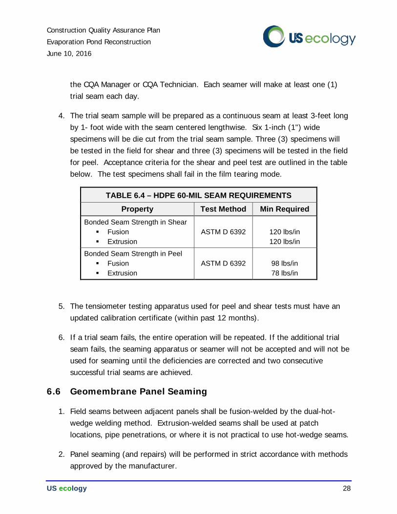
Construction Quality Assurance Plan
Evaporation Pond Reconstruction
June 10, 2016
US ecology 28
the CQA Manager or CQA Technician. Each seamer will make at least one (1) trial seam each day.
4. The trial seam sample will be prepared as a continuous seam at least 3-feet long by 1- foot wide with the seam centered lengthwise. Six 1-inch (1") wide specimens will be die cut from the trial seam sample. Three (3) specimens will be tested in the field for shear and three (3) specimens will be tested in the field for peel. Acceptance criteria for the shear and peel test are outlined in the table below. The test specimens shall fail in the film tearing mode.
TABLE 6.4 – HDPE 60-MIL SEAM REQUIREMENTS
Property Test Method Min Required
Bonded Seam Strength in Shear
Fusion
Extrusion
ASTM D 6392
120 lbs/in
120 lbs/in
Bonded Seam Strength in Peel
Fusion
Extrusion
ASTM D 6392
98 lbs/in
78 lbs/in
5. The tensiometer testing apparatus used for peel and shear tests must have an updated calibration certificate (within past 12 months).
6. If a trial seam fails, the entire operation will be repeated. If the additional trial seam fails, the seaming apparatus or seamer will not be accepted and will not be used for seaming until the deficiencies are corrected and two consecutive successful trial seams are achieved.
6.6 Geomembrane Panel Seaming
1. Field seams between adjacent panels shall be fusion-welded by the dual-hot-wedge welding method. Extrusion-welded seams shall be used at patch locations, pipe penetrations, or where it is not practical to use hot-wedge seams.
2. Panel seaming (and repairs) will be performed in strict accordance with methods approved by the manufacturer.
Construction Quality Assurance Plan
Evaporation Pond Reconstruction
June 10, 2016
US ecology 29
3. All foreign matter (dirt, water, oil, etc.) will be removed from the edges to be bonded. No solvents will be used to clean the geomembrane layer.
4. For extrusion welds, grinding/buffing shall be conducted to remove oxidized material at the seam locations. This shall be done in accordance with EPA/530-SW-91-051 and the following requirements:
a. The grinding shall not extend more than ¼ inch beyond the limit of the extrudate after seam completion.
b. Grinding shall be performed preferentially in a perpendicular path across the seam.
c. The depth of grinding shall be less than 10 percent of the sheet thickness.
5. Table 6.4 outlines the requirements for fusion and extrusion seams.
6. No seaming will be attempted above 40°C (104°F) ambient air temperatures. Field seaming shall not be done if ambient air temperature is below 1°C (34°F).
7. Seams at panel corners of 3 or 4 sheets will be completed with a patch having a minimum dimension of 24 inches (24"), extrusion welded to the parent sheet.
8. No folds, large wrinkles, or fish mouths will be allowed in the seam. Where wrinkles or folds occur, the material will be cut, overlapped, and welded. During wrinkle or fold repairs, adjacent geomembrane may not necessarily be required to meet the 3 to 4-inch minimum overlap if approved by the CQA personnel.
9. All welding equipment shall be handled/operated in a manner that minimizes the potential for damage to the installed liner.
10. All cross seams are to be patched with a 12-inch-diameter patch where they intersect.
11. Each field seam shall be identified by writing the following information on the geomembrane near the seam with a waterproof marker:
a. Date, starting time, and mark at starting point of weld
Construction Quality Assurance Plan
Evaporation Pond Reconstruction
June 10, 2016
US ecology 30
b. Welder’s name or identifying initials
c. Completion time and mark at ending point of weld
6.7 Geomembrane Seam Testing
All geomembrane seams will be tested and evaluated prior to acceptance. Testing of the seams will be conducted by the geosynthetic Installer under observation by CQA personnel. Additional testing may be requested to verify that the geomembrane seams meet the specifications.
1. Non-Destructive Testing
Continuous, non-destructive testing will be performed on all seams by the geosynthetic Installer. The entire length of all seams will be non-destructively tested by vacuum box or air pressure (double fusion seam only) for integrity after the seams are field welded to ensure geomembrane integrity is not compromised. The CQA Manager or CQA Technician shall be notified when non-destructive testing occurs so that these tests may be witnessed. All indicated leaks will be isolated and repaired as described in a later section.
a. Air-Pressure Testing
The entire length of all dual-tracked fusion welds will be air tested in accordance with GRI GM6. The ends of the air channel of the dual-track fusion weld must be sealed and pressured to approximately 30 psi. The air pump must then be shut off and the air pressure observed after 5 minutes. A loss of less than 3 psi is acceptable if it is determined that the air channel is not blocked between the sealed ends. A loss of pressure greater than 3 psi or a pressure that does not stabilize, indicates the presence of a seam leak which must then be isolated and repaired by following the procedures described in Section 6.9, Geomembrane Repairs. The CQA personnel should observe and record all pressure gauge readings.
b. Vacuum-Box Testing
Construction Quality Assurance Plan
Evaporation Pond Reconstruction
June 10, 2016
US ecology 31
Vacuum-box testing in accordance with ASTM D 4437 will be performed along all extrusion welded seams. The seams will be observed for leaks while subjected to this vacuum, in accordance with the test standard.
2. Destructive Testing
a. Destructive testing will be performed at least once within each 1,000 linear feet of production seam and at least once per welding machine per day. Additional destructive test samples may be required at the discretion of the CQA personnel.
b. The locations will be selected by the CQA personnel in such a manner as to representatively sample the geomembrane seam quality for the entire installation. At a minimum, a destructive test will be performed for each welding machine/seaming technician combination used for seaming or repairs.
c. Destructive tests samples shall be obtained by the geosynthetic Installer and laboratory tested at the Contractor’s QC laboratory.
d. The selected destruct samples shall be a minimum of 10-inches wide by 36-inches long, with the seam centered lengthwise. The sample shall be cut into three equal portions; one (1) for immediate field testing by the geosynthetic installer; one (1) for destructive testing performed at the QC testing laboratory, and one (1) delivered to the CQA Manager for periodic confirmation testing or archival.
e. Each sample location will be recorded and numbered for the as-built record.
f. Field testing by the geosynthetic installer will include at least four (4) shear test specimens and four (4) peel test specimens.
g. QC laboratory testing will consist of five (5) shear test specimens and five (5) peel test specimens. Laboratory shear and peel testing will be performed in accordance with ASTM D 6392.
Construction Quality Assurance Plan
Evaporation Pond Reconstruction
June 10, 2016
US ecology 32
h. All field-tested specimens from destructive test locations must pass in both shear and peel for the seam to be considered passing. QC laboratory testing must confirm these field results by meeting the following criteria:
1. All specimens tested in the peel mode must fail in FTB.
2. At least 4 specimens from each peel and shear determination must meet the minimum specified strength requirements outlined in Table 6.4.
6.8 Geomembrane Non-Conforming Tests
1. If there is a sample failure the geosynthetic Installer may:
a. Cap the seam between any two previously passing seam test locations that include the failure location, or
b. Cut additional samples on each side of the failure location (10-foot minimum each way) and repeat sample procedure for each side. If both sides pass, cap the field seam between the two passing locations. If either fails, repeat the process of taking samples for testing. Each field seam shall be bounded by two passing test locations prior to acceptance.
6.9 Geomembrane Repairs
1. Repair areas will be identified and marked on the geomembrane and recorded on the QC repair log.
2. Damaged geomembrane areas and destructive test sample areas of geomembrane will be repaired by the geosynthetic installer by construction of a cap strip. The cap strip will extend a minimum of 6 inches (6") in all directions from the area of concern. All patches or cap strips shall have corners rounded to a 3-inch radius or wider.
3. The selected width of the replacement strip shall ensure that the fusion weld is not less than 8 inches from any existing weld.
Construction Quality Assurance Plan
Evaporation Pond Reconstruction
June 10, 2016
US ecology 33
4. No repairs will be made to seams by application of an extrusion bead to a seam edge previously welded by fusion or extrusion methods. Spot welding and extrusion beads may be used to repair surface flaws or irregularity.
5. Repaired areas will be non-destructive tested for seam integrity. At the discretion of the CQA Manager or CQA Technician, destructive tests may be conducted on the repaired areas.
6.10 Geomembrane CQA Documentation
The following information, at a minimum, will be used to document the installation of geomembranes:
1. Manufacturer's quality control certification;
2. Conformance test reports from Independent Geosynthetics Testing Laboratory;
3. Geomembrane roll identification information;
4. Subgrade acceptance certifications signed by Geosynthetic Installer and CQA;
5. Results of trial seam tests, non-destructive tests, and destructive tests;
6. A comprehensive seaming log and repair log; and
7. A scaled plot, indicating the panel layout, seam locations, destructive test locations, and repair locations.
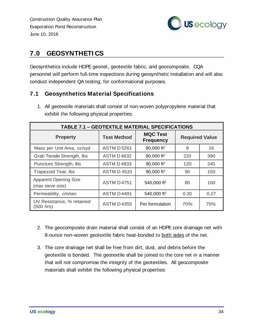
Construction Quality Assurance Plan
Evaporation Pond Reconstruction
June 10, 2016
US ecology 34
7.0 GEOSYNTHETICS
Geosynthetics include HDPE geonet, geotextile fabric, and geocomposite. CQA personnel will perform full-time inspections during geosynthetic installation and will also conduct independent QA testing, for conformational purposes.
7.1 Geosynthetics Material Specifications
1. All geotextile materials shall consist of non-woven polypropylene material that exhibit the following physical properties:
TABLE 7.1 – GEOTEXTILE MATERIAL SPECIFICATIONS
Property Test Method MQC Test
Frequency Required Value
Mass per Unit Area, oz/syd ASTM D 5261 90,000 ft2 8 16
Grab Tensile Strength, lbs ASTM D 4632 90,000 ft2 220 390
Puncture Strength, lbs ASTM D 4833 90,000 ft2 120 240
Trapezoid Tear, lbs ASTM D 4533 90,000 ft2 90 150
Apparent Opening Size
(max sieve size) ASTM D 4751 540,000 ft2 80 100
Permeability, cm/sec ASTM D 4491 540,000 ft2 0.30 0.27
UV Resistance, % retained (500 hrs)
ASTM D 4355 Per formulation 70% 70%
2. The geocomposite drain material shall consist of an HDPE core drainage net with 8-ounce non-woven geotextile fabric heat-bonded to both sides of the net.
3. The core drainage net shall be free from dirt, dust, and debris before the geotextile is bonded. The geotextile shall be joined to the core net in a manner that will not compromise the integrity of the geotextiles. All geocomposite materials shall exhibit the following physical properties:
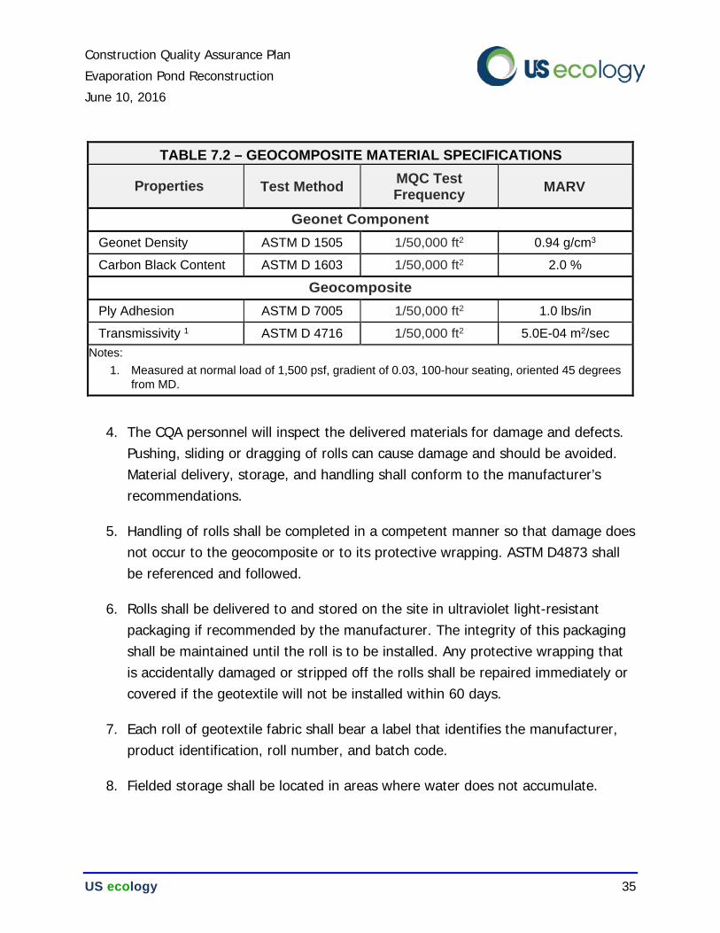
Construction Quality Assurance Plan
Evaporation Pond Reconstruction
June 10, 2016
US ecology 35
TABLE 7.2 – GEOCOMPOSITE MATERIAL SPECIFICATIONS
Properties Test Method MQC Test Frequency MARV
Geonet Component
Geonet Density ASTM D 1505 1/50,000 ft2 0.94 g/cm3
Carbon Black Content ASTM D 1603 1/50,000 ft2 2.0 %
Geocomposite
Ply Adhesion ASTM D 7005 1/50,000 ft2 1.0 lbs/in
Transmissivity 1 ASTM D 4716 1/50,000 ft2 5.0E-04 m2/sec
Notes:
1. Measured at normal load of 1,500 psf, gradient of 0.03, 100-hour seating, oriented 45 degrees
from MD.
4. The CQA personnel will inspect the delivered materials for damage and defects. Pushing, sliding or dragging of rolls can cause damage and should be avoided. Material delivery, storage, and handling shall conform to the manufacturer’s recommendations.
5. Handling of rolls shall be completed in a competent manner so that damage does not occur to the geocomposite or to its protective wrapping. ASTM D4873 shall be referenced and followed.
6. Rolls shall be delivered to and stored on the site in ultraviolet light-resistant packaging if recommended by the manufacturer. The integrity of this packaging shall be maintained until the roll is to be installed. Any protective wrapping that is accidentally damaged or stripped off the rolls shall be repaired immediately or covered if the geotextile will not be installed within 60 days.
7. Each roll of geotextile fabric shall bear a label that identifies the manufacturer, product identification, roll number, and batch code.
8. Fielded storage shall be located in areas where water does not accumulate.
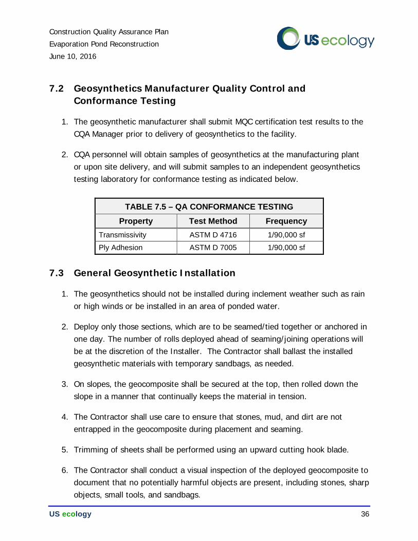
Construction Quality Assurance Plan
Evaporation Pond Reconstruction
June 10, 2016
US ecology 36
7.2 Geosynthetics Manufacturer Quality Control and Conformance Testing
1. The geosynthetic manufacturer shall submit MQC certification test results to the CQA Manager prior to delivery of geosynthetics to the facility.
2. CQA personnel will obtain samples of geosynthetics at the manufacturing plant or upon site delivery, and will submit samples to an independent geosynthetics testing laboratory for conformance testing as indicated below.
7.3 General Geosynthetic Installation
1. The geosynthetics should not be installed during inclement weather such as rain or high winds or be installed in an area of ponded water.
2. Deploy only those sections, which are to be seamed/tied together or anchored in one day. The number of rolls deployed ahead of seaming/joining operations will be at the discretion of the Installer. The Contractor shall ballast the installed geosynthetic materials with temporary sandbags, as needed.
3. On slopes, the geocomposite shall be secured at the top, then rolled down the slope in a manner that continually keeps the material in tension.
4. The Contractor shall use care to ensure that stones, mud, and dirt are not entrapped in the geocomposite during placement and seaming.
5. Trimming of sheets shall be performed using an upward cutting hook blade.
6. The Contractor shall conduct a visual inspection of the deployed geocomposite to document that no potentially harmful objects are present, including stones, sharp objects, small tools, and sandbags.
TABLE 7.5 – QA CONFORMANCE TESTING
Property Test Method Frequency
Transmissivity ASTM D 4716 1/90,000 sf
Ply Adhesion ASTM D 7005 1/90,000 sf
Construction Quality Assurance Plan
Evaporation Pond Reconstruction
June 10, 2016
US ecology 37
7. Panels will be positioned such that the number of field seams are minimized, field seams are oriented parallel to the line of the maximum, and horizontal seams are located at least 5 ft from the toe of the slope.
8. Vehicular traffic will not be allowed on the geosynthetic materials prior to placement of the protective soil layers, with the exception of low-ground pressure equipment (ATVs or other small rubber tired equipment). Other support equipment may not be set directly on the geosynthetics, it must be placed on a sacrificial surface or rub sheet.
9. Personnel working on the geosynthetics will not smoke, wear damaging shoes, or engage in any other activity likely to damage the geosynthetics.
10. During deployment, the geosynthetic layers be will inspected to insure that they are free from holes, tears, punctures, or contamination by foreign matter. Any damaged materials will be repaired as directed by the CQA personnel.
7.4 Geosynthetics Panel Seaming/Tying
Geocomposite panels, geotextile cushion panels, and geotextile filter panels shall be overlapped and seamed as outlined in this section.
Geocomposite Geonet Components
Cable ties of contrasting color shall be used to join adjacent drainage cores.
a. Adjacent longitudinal edges of geonet will be overlapped at least 4 inches (4"). These overlaps will be secured with ties at five foot (5') intervals.
b. Geonet roll ends will be overlapped 1 ft in areas with less than 10% slope. Ties will be applied at three foot (3') intervals.
c. In areas greater than 10% slope, roll ends will be overlapped 2 ft. Two staggered rows of ties will be applied at 12 inch (12") intervals.
Construction Quality Assurance Plan
Evaporation Pond Reconstruction
June 10, 2016
US ecology 38
Geocomposite Geotextile Components
The upper geotextile layer of each geocomposite will be overlapped at least 4 inches (4") and will be continuously sewn. The bottom geotextile layer of a geocomposite does not need to be overlapped.
Geotextile Panels
Geotextile cushion panels and filter panels shall be overlapped at least 4 inches (4") and will be continuously sewn.
7.5 Geosynthetics Repairs
1. Any holes or tears in the geocomposite or geotextile will be repaired by placing a patch extending 2 ft beyond the edges of the hole or tear.
2. For geocomposites, the patch will be secured by tying fasteners through the geonet of the patch to the underlying geocomposite geonet. The patch will be secured every 6 inches (6”) with cable ties. The top geotextile component will be heat sealed to the top geotextile of the geocomposite needing repair. Thermal bonds shall be performed with a lyster, use of butane torches will not be allowed on the geocomposite material.
3. If the hole or tear width across the roll is more than 50% of the width of the roll, the damaged area will be cut out and replaced.
7.6 Geosynthetics CQA Documentation
All field seaming will be performed under the observation of the CQA personnel. The following information will be used to document the installation of geosynthetics:
1. Manufacturer quality control certification;
2. Geosynthetics roll identification information; and
3. Conformance test results from an independent geosynthetics testing laboratory.
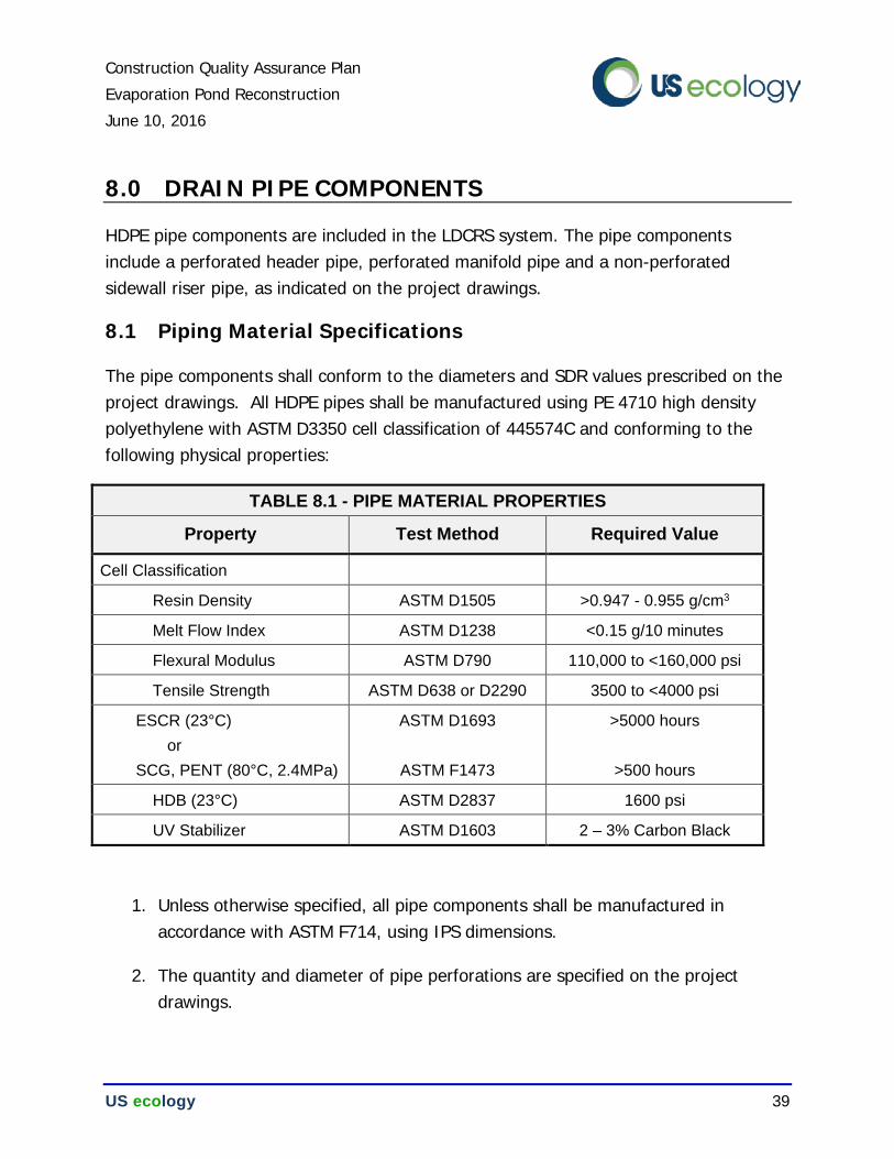
Construction Quality Assurance Plan
Evaporation Pond Reconstruction
June 10, 2016
US ecology 39
8.0 DRAIN PIPE COMPONENTS
HDPE pipe components are included in the LDCRS system. The pipe components include a perforated header pipe, perforated manifold pipe and a non-perforated sidewall riser pipe, as indicated on the project drawings.
8.1 Piping Material Specifications
The pipe components shall conform to the diameters and SDR values prescribed on the project drawings. All HDPE pipes shall be manufactured using PE 4710 high density polyethylene with ASTM D3350 cell classification of 445574C and conforming to the following physical properties:
TABLE 8.1 - PIPE MATERIAL PROPERTIES
Property Test Method Required Value
Cell Classification
Resin Density ASTM D1505 >0.947 - 0.955 g/cm3
Melt Flow Index ASTM D1238 <0.15 g/10 minutes
Flexural Modulus ASTM D790 110,000 to <160,000 psi
Tensile Strength ASTM D638 or D2290 3500 to <4000 psi
ESCR (23°C)
or
SCG, PENT (80°C, 2.4MPa)
ASTM D1693
ASTM F1473
>5000 hours
>500 hours
HDB (23°C) ASTM D2837 1600 psi
UV Stabilizer ASTM D1603 2 – 3% Carbon Black
1. Unless otherwise specified, all pipe components shall be manufactured in accordance with ASTM F714, using IPS dimensions.
2. The quantity and diameter of pipe perforations are specified on the project drawings.
Construction Quality Assurance Plan
Evaporation Pond Reconstruction
June 10, 2016
US ecology 40
8.2 Piping Manufacturer Quality Control
1. The manufacturer shall certify that pipe materials meet the respective cell classification(s) identified in the previous section and submit test results for the following properties from each production lot, to substantiate the cell classification:
a. Density – ASTM D1505
b. Melt Flow Index - ASTM D1238
c. Tensile Strength at Yield – ASTM D638 or D2290
d. Carbon Content – ASTM D1603
e. IPS Dimensions – ASTM F714
2. Quality control certification shall also identify the parent material and the manufacture dates.
8.3 Piping Installation
1. Pipe sections will be welded together so that individual sections are fused at the joints, in accordance with manufacturer’s instruction and recommendations.
2. Handling of plastic pipe shall be done in a competent manner such that damage does not occur to the pipe. Only wide fabric choker slings shall be used to lift, move, or lower pipe and fittings.
3. Cuts, gouges and scratches in the HDPE pipe components shall be limited to 10% of the wall thickness, unless otherwise approved by the Engineer.
8.4 Piping Survey Control
1. The completed alignment of each pipe component shall be documented by the Contractor, providing survey coordinates at an interval of 50 feet or less.
Construction Quality Assurance Plan
Evaporation Pond Reconstruction
June 10, 2016
US ecology 41
8.5 Piping CQA Documentation
The following is a summary of information which will contain documentation of the installation of the leachate collection and leak detection piping:
1. MQC certification for the piping; and
2. An as-built record of the LDCRS pipe coordinates and elevations.
Construction Quality Assurance Plan
Evaporation Pond Reconstruction
June 10, 2016
US ecology 42
9.0 FROST PROTECTION AGGREGATES
Frost protection aggregates include the cover sand layer which will be installed over the synthetic liner components, riprap aggregates on the sidewalls, and cover gravel aggregates across the floor, as illustrated on the project drawings.
9.1 Frost Protection Material Requirements
The purpose of these aggregates is to protect the underlying compacted clay liner against the detrimental effects of frost penetration. Density measurements are not required for the frost protection aggregates. Frost protection aggregates shall conform to the following descriptions.
COVER SAND
Cover sand shall be obtained from on-site soil stockpiles and required on-site excavations. Acceptable materials shall be free of stones greater than 3-inches, debris, roots, or any significant amount of organic matter. Materials which classify as CL, CH, ML, SC, GC, GP, GW, OH or OL according to ASTM D 2847 are unsuitable for use as cover sand. Cover sand shall not be placed while saturated or in a frozen condition.
Cover sand placement shall commence near the toe of each sidewall and progress upward, to avoid the development of unnecessary tension in the underlying synthetic layers. Cover sand aggregates shall be spread into a single uniform lift with the prescribed thickness. Cover sand aggregates shall be compacted by tracking a minimum of four passes with a D6 dozer or an approved equivalent. CQA personnel shall approve adequate placement of cover sand aggregates prior to deployment of the next layer.
COVER GRAVEL
Cover gravel materials shall be obtained from on-site soil stockpiles or the on-site excavations. Acceptable materials shall be granular and free of debris, roots, or any significant amount of organic matter. Cover gravel materials which shall classify as GP, GW, GM, SP, SW, SM or a combination description (such as GP-GM) according
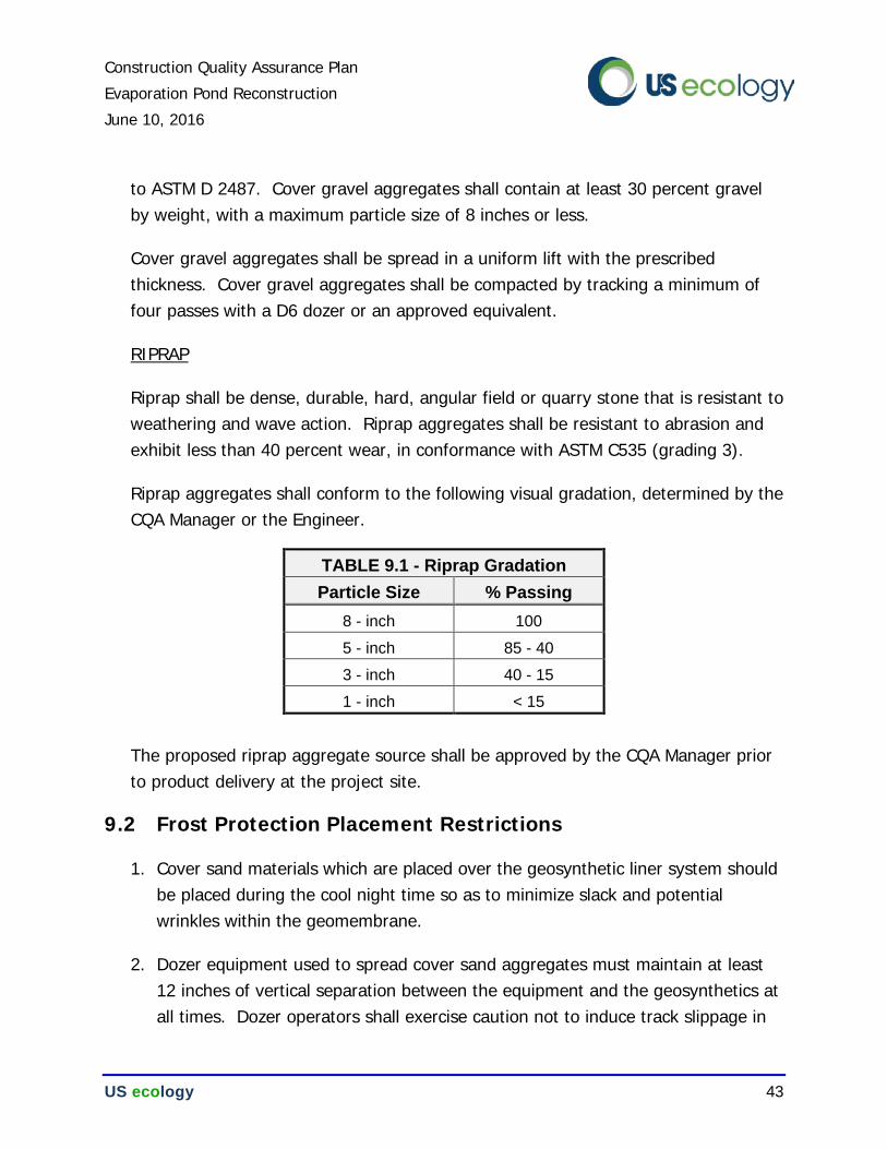
Construction Quality Assurance Plan
Evaporation Pond Reconstruction
June 10, 2016
US ecology 43
to ASTM D 2487. Cover gravel aggregates shall contain at least 30 percent gravel by weight, with a maximum particle size of 8 inches or less.
Cover gravel aggregates shall be spread in a uniform lift with the prescribed thickness. Cover gravel aggregates shall be compacted by tracking a minimum of four passes with a D6 dozer or an approved equivalent.
RIPRAP
Riprap shall be dense, durable, hard, angular field or quarry stone that is resistant to weathering and wave action. Riprap aggregates shall be resistant to abrasion and exhibit less than 40 percent wear, in conformance with ASTM C535 (grading 3).
Riprap aggregates shall conform to the following visual gradation, determined by the CQA Manager or the Engineer.
TABLE 9.1 - Riprap Gradation
Particle Size % Passing
8 - inch 100
5 - inch 85 - 40
3 - inch 40 - 15
1 - inch < 15
The proposed riprap aggregate source shall be approved by the CQA Manager prior to product delivery at the project site.
9.2 Frost Protection Placement Restrictions
1. Cover sand materials which are placed over the geosynthetic liner system should be placed during the cool night time so as to minimize slack and potential wrinkles within the geomembrane.
2. Dozer equipment used to spread cover sand aggregates must maintain at least 12 inches of vertical separation between the equipment and the geosynthetics at all times. Dozer operators shall exercise caution not to induce track slippage in
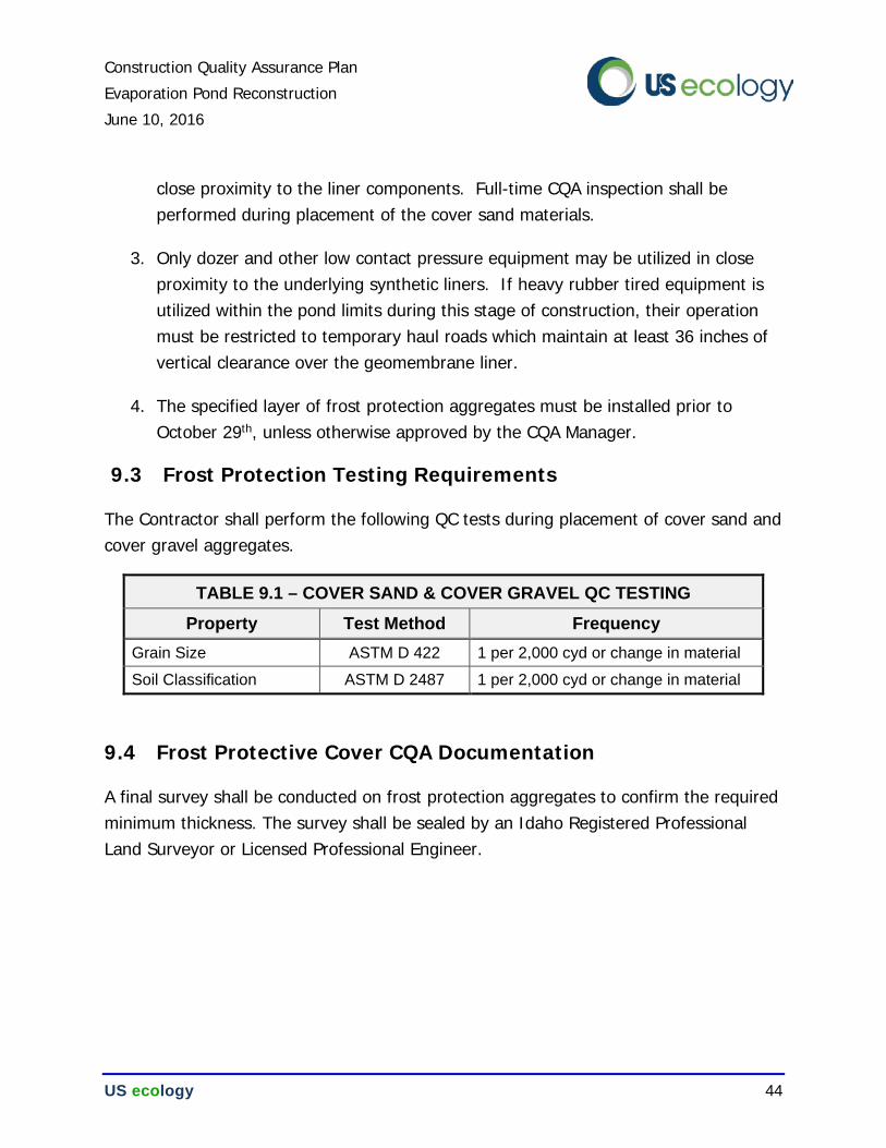
Construction Quality Assurance Plan
Evaporation Pond Reconstruction
June 10, 2016
US ecology 44
close proximity to the liner components. Full-time CQA inspection shall be performed during placement of the cover sand materials.
3. Only dozer and other low contact pressure equipment may be utilized in close proximity to the underlying synthetic liners. If heavy rubber tired equipment is utilized within the pond limits during this stage of construction, their operation must be restricted to temporary haul roads which maintain at least 36 inches of vertical clearance over the geomembrane liner.
4. The specified layer of frost protection aggregates must be installed prior to October 29th, unless otherwise approved by the CQA Manager.
9.3 Frost Protection Testing Requirements
The Contractor shall perform the following QC tests during placement of cover sand and cover gravel aggregates.
TABLE 9.1 – COVER SAND & COVER GRAVEL QC TESTING
Property Test Method Frequency
Grain Size ASTM D 422 1 per 2,000 cyd or change in material
Soil Classification ASTM D 2487 1 per 2,000 cyd or change in material
9.4 Frost Protective Cover CQA Documentation
A final survey shall be conducted on frost protection aggregates to confirm the required minimum thickness. The survey shall be sealed by an Idaho Registered Professional Land Surveyor or Licensed Professional Engineer.
Construction Quality Assurance Plan
Evaporation Pond Reconstruction
June 10, 2016
US ecology 45
10.0 CQA REPORT DOCUMENTATION
10.1 General
Inspection, sampling, and other CQA activities are performed for the purpose of substantiating that construction activities were accomplished in accordance with the project plans and drawings. During construction, all CQA documentation will be maintained under the responsible charge of the CQA Manager. A brief description of the documentation required for CQA is provided in the sections below.
10.2 CQA Field Reports
Daily Reports and weekly summary reports will be prepared by the CQA Manager or the CQA Technician to provide a complete chronological history of construction activities associated with the surface impoundment. These reports should include the following information:
1. Date and project name;
2. Weather conditions;
3. Summaries of meetings held and actions recommended or taken;
4. Locations and description of construction activities;
5. Construction equipment, personnel, and subcontractors at the facility;
6. Description of materials received at the facility, and status of the associated quality control data.
10.3 As-built Record Drawings
Record drawings or as-built drawings will be prepared to document the actual lines and grades for the constructed design components. The CQA Manager will coordinate preparation of various record drawings identified in this CQA Plan, whether prepared by an Idaho Registered Professional Land Surveyor, the geosynthetic installer, or by CQA personnel.
Construction Quality Assurance Plan
Evaporation Pond Reconstruction
June 10, 2016
US ecology 46
Record drawings for liner construction shall include the following:
1. As-built survey of the prepared subgrade signed and sealed by an Idaho Registered Professional Land Surveyor. The as-built survey will include area of subgrade construction, survey locations and elevations at respective survey locations.
2. As-built survey of compacted clay layer signed and sealed by an Idaho Registered Professional Land Surveyor. The as-built survey will include area of liner construction, survey locations, elevations at respective survey locations and thickness determination.
3. A scaled plot, indicating the panel layout, seam locations, destructive test locations, and repair locations of geomembrane layers.
4. As-built record of the LDCRS pipes signed and sealed by an Idaho Registered Professional Land Surveyor or a Professional Engineer. The as-built surveys will include location of collection piping, survey locations, and elevations.
5. An as-built survey of the upper frost protection aggregate layer signed and sealed by an Idaho Registered Professional Land Surveyor. The as-built survey will include total thickness determination for each survey location.
6. A full set of the project construction drawings, annotated with any subsequent redlines, additions or design variations, signed and sealed by the CQA Manager.
10.4 Final Certification
Upon completion of construction, the CQA Manager shall prepare a Construction Quality Assurance Report, which describes the tests, inspections, and measurements performed, their results, and all other bases for conclusion that the facility unit has been constructed, installed, and functions in conformance with the project plans. At a minimum, the CQA Report will include the following items:
• Description of the construction processes and sequences employed by the Contractors.
Construction Quality Assurance Plan
Evaporation Pond Reconstruction
June 10, 2016
US ecology 47
• CQA observations, construction problems and corrective actions, and any deviations from the original design.
• Weekly field reports and associated photo logs.
• Laboratory and field testing results of the compacted clay liner and earthwork components.
• Manufacturer’s laboratory test results and certification(s) of all materials used during the construction.
• Independent laboratory testing results and certification(s) for HDPE resin, geomembrane, and welds.
• Subgrade acceptance forms.
• As-built drawings.
The final CQA report will serve as the permanent record of the completed construction. The document will serve to assure the regulatory agencies that the hazardous waste management unit was constructed in accordance with the permitted project plans.
Construction Quality Assurance Plan
Evaporation Pond Reconstruction
June 10, 2016
US ecology 48
11.0 REFERENCES
American Geotechnics, (2012) Landfill Engineering Report, Cell 16 Subcells 16-1 & 16-2, Grand View Facility. Boise, ID. February 8, 2012.
American Geotechnics, (2005) Low Permeability Soil Test Pad Report / Cell 15-Phase II, Grand View Facility. Boise, ID. May 18, 2005.