Embed Size (px)
Citation preview

ATTACHMENT I TO IPN-91-040
PROPOSED TECHNICAL SPECIFICATION CHANGES
RELATED TO
PRESSURE-TEMPERATURE AND OVERPRESSURE PROTECTION SYSTEM UMITS
NEW YORK POWER AUTHORITY INDIAN POINT 3 NUCLEAR POWER PLANT
DOCKET NO. 50-286 DPR-64
R111070131 911C)2E
FO ADCK05008

APPENDIX A - TECHNICAL SPECIFICATION AND BASES INDIAN POINT NUCLEAR GENERATING UNIT NO. 3
TABLE OF CONTENTS
Section Title Page
TECHNICAL SPECIFICATIONS
1 Definitions 1-1
2 Safety Limits and Limiting Safety System Settings 2.1-1 2.1 Safety Limit, Reactor Core 2.1-1 2.2 Safety Limit, Reactor Coolant System Pressure 2.2-1 2.3 Limiting Safety System Settings, Protective
Instrumentation 2.3-1 3 Limiting Conditions for Operation 3.1-1 3.1 Reactor Coolant System 3.1-1
Operational Components 3.1-1 Heatup and Cooldown 3.1-17 Minimum Conditions for Criticality 3.1-25 Primary Coolant Activity 3.1-26 Maximum Reactor Coolant Oxygen, Chloride and Fluoride Concentration 3.1-29 Leakage of Reactor Coolant 3.1-31 Secondary Coolant Activity 3.1-35
3.2 Chemical and Volume Control System 3.2-1 3.3 Engineered Safety Features 3.3-1
Safety Injection and Residual Heat Removal Systems 3.3-1 Containment Cooling and Iodine Removal Systems 3.3-5 Isolation Valve Seal Water System 3.3-7 Weld Channel and Penetration Pressurization System 3.3-8 Component Cooling System 3.3-9 Service Water System 3.3-10 Hydrogen Recombiner and Containment Hydrogen Monitoring Systems 3.3-11 Control Room Ventilation System 3.3-12
3.4 Steam and Power Conversion System 3.4-1 3.5 Instrumentation Systems 3.5-1 3.6 Containment System 3.6-1
Containment Integrity 3.*6-1 Internal Pressure 3.6-1 Containment Temperature 3.6-2
3.7 Auxiliary Electrical Systems 3.7-1 3.8 Refueling, Fuel Handling and Storage 3.8-1 3.9 Radioactive Materials Management 3.9-1
i
Amendment No. Y9, XqX,

3. LIMITING CONDITIONS FOR OPERATION
For the cases where no exception time is specified for inoperable components, this time is assumed to be zero.
3.1 REACTOR COOLANT SYSTEM
Applicability
Applies to the operating status of the Reactor Coolant System; operational components; heatup; cooldown; criticality; activity; chemistry and leakage.
Objective
To specify those limiting conditions for operation of the Reactor Coolant System which must be met to ensure safe reactor operation.
Specification
A. OPERATIONAL COMPONENTS
1. Coolant Pumps
a. When a reduction is made in the boron concentration of the reactor coolant, at least one reactor coolant pump or one residual heat removal pump (connected to the Reactor Coolant System ) shall be in operation.
b. (1) When the reactor coolant system Tavg is greater than 3501F and electrical power is available to the reactor coolant pumps, and as permitted during special plant evolutions, at least one reactor coolant pump shall be in operation. All reactor coolant pumps may be de-energized for up to 1 hour provided no operations are permitted that would cause dilution of the reactor coolant system boron concentration, and core outlet temperature is maintained at least 10OF below saturation temperature.
(2) When the reactor is subcritical and reactor coolant system T.r, is greater than 350 0F, control bank withdrawal shall be prohibited unless four reactor coolant pumps are operating.
c. When the reactor coolant system Tavg is greater than 200OF and less than 350 0F, and as permitted during special plant evolutions, at least one reactor coolant pump or one residual heat removal pump (connected to the Reactor Coolant System) shall be in operation. All reactor coolant pumps may be deenergized with RHR not in service for up to I hour provided no operations are permitted that would cause dilution of the reactor coolant system boron concentration, and core outlet temperature is maintained at least 101F below saturation temperature.
Amendment No. , , , $, $7, f, $,
3.1-1

d. When the reactor coolant system Tavs is less than 200'F, but not in the refueling operation condition, and as permitted during special plant evolutions, at least one residual heat removal pump (connected to the Reactor Coolant System) shall be in operation. This RHR pump may be out of service for up to 1 hour provided no operations are permitted that would cause dilution of the reactor coolant system boron concentration, and core outlet temperature is maintained at least 10'F below saturation temperature.
e. When the reactor is critical and above 2% rated power, except for natural circulation tests, at least two reactor coolant pumps shall be in operation.
f. The reactor shall not be operated at power levels above 10% rated power with less than four (4) reactor coolant loops in operation.
g. If the requirements of 3.l.A.l.e and 3.l.A.l.f above cannot be satisfied, the reactor shall be brought to the hot shutdown condition within I hour.
h., A reactor coolant pump (RCP) may not be started (or jogged) when the RCS cold leg temperature (Tcold) is at or below 332°F, with no other RCP's operating, unless RCS make up is not in excess of RCS losses, and one of the following requirements is met:
(1) The OPS is operable, steam generator pressure is not decreasing, and the temperature of each steam generator is less than or equal to the coldest TCold;
Or
(2) The OPS is operable, the temperature of the hottest steam generator exceeds the coldest TCOld by no more than 640F, pressurizer level is at or below 75 percent, and Tcold is as per Figure 3.1.A-1;
Or
(3) The OPS is inoperable, steam generator pressure is not decreasing, the temperature of each steam generator is less than or equal to the coldest Tcold, pressurizer level is at or below 75 percent, and the RCS pressure does not exceed that given by Curve I on Fig. 3.1.A-2;
Or
(4) The OPS is inoperable, the temperature of the hottest steam generator exceeds the coldest Tcold by no more than 641F, and pressurizer level and RCS pressure do not exceed the boundaries given on Fig. 3.1.A-4.
Amendment 9., X, 97, 0, Y,
3.1-2

i. Additional pumps may not be started (or jogged) unless the OPS is operable and the pressurizer level is not increasing.
(1) Specification 3.l.A.l.i above may be modified to allow the OPS inoperable, providing the temperature of each steam generator has remained less than or equal to the coldest Tcold since the first RCP start, pressurizer level is at or below 75 percent and the RCS pressure does not exceed that given by Curve I on Fig. 3.1.A-2.
(2) Specification 3.l.A.l.i above may be further modified.to allow the OPS inoperable and the temperature of the hottest steam generator to be no greater than 64°F higher than the coldest Tcold, provided that pressurizer level is at or below 75 percent and RCS pressure does not exceed that given by Curve II on Fig. 3.1.A-2.
j. Following the start of one or more RCP's and prior to reaching 332'F, the RCS pressure shall not exceed that given by Curves I and II on Fig. 3.1.A-3 as appropriate.
Amendment No. 97, Y, Y,
3.1-3

2. Safety Valves
a. At least one pressurizer code safety valve shall be operable, or an opening greater than or equal to the size of one code safety valve flange to allow for pressure relief, whenever the reactor head is on the vessel except for hydrostatically testing the RCS in accordance with Section XI of the ASME Boiler and Pressure Vessel Code.
b. All pressurizer code safety valves shall be operable whenever the reactor is above the cold shutdown' condition except during reactor coolant system hydrostatic tests and/or safety valve settings.
c. The pressurizer code safety valve lift setting shall be set at 2485 psig with +1% allowance for error.
3. Pressurizer Heaters
Whenever the reactor is above the hot shutdown condition, the pressurizer shall be operable with at least 150 kw of pressurizer heaters.
a. With less than 150 kw of pressurizer heaters operable, restore the required inoperable heaters within 72 hours or be in at least hot shutdown within an additional 6 hours.
4. Power Operated Relief Valves
Whenever the reactor coolant system is above 400'F, the power operated relief valves (PORVs) shall be operable or their associated block valves closed.
a. If the block valve is closed because of an inoperable PORV, the control power for the block valve must be removed.
b. If the above conditions cannot be satisfied within 1 hour, be in at least hot shutdown withi-n 6 hours and in cold shutdown within the following 30 hours.
5. Power Operated Relief Block Valves
Whenever the reactor coolant system is above 400*F, the motor operated block valves shall be operable or closed.
a. If the block valve is inoperable, the control power is to be removed.
b. If the above conditions cannot be satisfied within 1 hour be in at least hot shutdown within the following 30 hours.
6. Reactor Coolant System Tavg
During steady state operation, the maximum indicated T,9& shall not exceed 578.3'F.
Amendment No. 7Y, PY, ~
3.1-4

7. REACTOR VESSEL HEAD VENTS
Whenever the reactor coolant system is above 350'F, two reactor vessel head vent paths consisting of two valves in series with power available from emergency buses shall be OPERABLE.
a. If one of the above reactor vessel head vent paths is inoperable, startup and/or power operation may continue provided the inoperable vent path is maintained closed with power removed from the valve actuator of all the valves in the inoperable vent path. Restore the inoperable vent path to operable status within 90 days, or be in hot shutdown within 6 hours and be below 350°F within the following 30 hours.
b. With both reactor vessel head vent paths inoperable restore one vent path to operable status within 7 days or be in hot shutdown within 6 hours and be below 3501F within the following 30 hourS.
8. OVERPRESSURE PROTECTION SYSTEM (OPS)
a. When the RCS temperature is below 3320F and the RCS is not depressurized and vented with an equivalent opening of at least 2.00 square inches, the OPS shall be "armed" and "operable". Both OPS PORVs shall have lift settings not to exceed those given by Curve III (OPS PORV setpoint limit curve) on Fig. 3.1.A-3.
b. The requirements of 3.l.A.8.a. may be modified to allow one PORV and/or its series MOV to be inoperable for a maximum of seven (7) consecutive days. If the single PORV and/or its series MOV are not restored to meet the requirements of 3.l.A.8.a. within the seven (7) day period, or if both PORVs and/or their series MOVs are inoperable when required to be operable by 3.l.A.8.a., then one of the following actions shall be performed:
(1) The RCS must be depressurized and vented with an
equivalent opening of at least 2.00 square inches;
Or
(2) The RCS must be heated in accordance with Specifications 3.l.A.l.h(3) and (4) and maintained above 370°F;
Or
(3) Restrict pressurizer level as per the curves referenced
below:
For up to 1 charging pump in operation with no SI pumps energized and aligned to feed the Reactor Coolant System, see Fig. 3.1.A-5.
Amendment No. f, 97,
3.1-5

For up to 3 charging pumps in operation concurrent with up to 1 SI pump energized and aligned to feed the Reactor Coolant System, see Fig. 3.1.A-6.
C. In the event the PORV's or the RCS vent(s) are used to mitigate an RCS pressure transient, a Special Report shall be prepared and submitted to the Commission pursuant to Specification 6.9.2.j within 30 days. The report shall describe the circumstances initiating the transient, the effect of the PORVs or vent(s) on the transient and any corrective action necessary to prevent recurrence.
Amendment No. AX, 07,
3.1-6

Basis
When the boron concentration of the Reactor Coolant System is to be reduced the process must be uniform to prevent sudden reactivity changes in the reactor. Mixing of the reactor coolant will be sufficient to maintain a uniform boron concentration if at least one reactor coolant pump or one residual heat removal pump is running while the change is taking place. The residual heat removal pump will circulate the primary system volume in approximately one half hour. The pressurizer is of no concern because of the low pressurizer volume and because the pressurizer boron concentration will be higher than that of the rest of the reactor coolant.
Heat transfer analyses show that reactor heat equivalent to 10% of rated power (P-7) can be removed with natural circulation only (1); hence, the requirement for one operating RCP above 350°F and two operating RCP's above 2% rated power provides a substantial safety factor. In addition, a single RCP or RHR pump (connected to the RCS) provides sufficient heat removal capability for removing decay heat.
The restriction on control bank withdrawal with less than four reactor coolant pumps operating when the reactor is subcritical and RCS T,, is greater than 350'F is necessary to conform with the assumptions used in the transient analyses for the uncontrolled control rod withdrawal event from subcritical condition. The FSAR safety analysis for uncontrolled control rod assembly withdrawal from a subcritical condition assumes all four reactor coolant pumps to be operating within the temperature range of concern. Using this assumption the DNB design basis is satisfied for the combination of the two banks of the maximum combined worth withdrawn at maximum speed. Since there is no mechanism by which the control rods can be automatically withdrawn due to a control system error when Tavg is between 3501F and the no-load temperature, such an event can only be initiated as a result of human error during rod manipulation. Prohibiting control bank withdrawal with less than four RCPs operating provides assurance that the plant is operated within the accident analysis assumptions.
The reactor shall not be operated at power levels above 10% rated power with less than four (4) reactor coolant loops in operation until safety analyses for less than four loop operation have been submitted by the licensee and approval for less than four loop operation at power levels above 10% rated power has been granted by the Commission. (See license condition 2.C. (3))
Each of the pressurizer code safety valves is designed to relieve 420,000 lbs. per hr. of saturated steam at the valve set point.
If no residual heat were removed by the Residual Heat Removal System the amount of steam which could be generated at safety valve relief pressure would be less than half the capacity of a single valve. One valve therefore provides adequate protection for overpressurization.
The combined capacity of the three pressurizer safety valves is greater than the maximum surge rate resulting from complete loss of load (2) without a direct reactor trip or any other control.
Amendment No. 0A, X7, yo,
3.1-7

The requirement that 150 kw of pressurizer heaters and their associated controls be capable of being supplied electrical power from an emergency bus provides assurance that these heaters can be energized during a loss of offsite power condition to maintain natural circulation at hot shutdown.
The power operated relief valves (PORVs) operate to relieve RCS pressure below the setting of the pressurizer code safety valves. These relief valves have remotely operated block valves to provide a positive shutoff capability should a relief valve become inoperable. The electrical power for both the relief valves and the block valves is capable of being supplied from an emergency power source to ensure the ability to seal off possible RCS leakage paths.
The limit on maximum indicated Tavg provides assurance that RCS temperatures are maintained within the normal steady state envelope of operation assumed in the safety analyses performed to support the Vantage 5 fuel reloads with asymmetric tube plugging among steam generators. A maximum full power Tcold of 547.9°F (including control deadband and measurement uncertainties) was assumed in these safety analyses. Restricting the maximum indicated Tavg to 578.30F assures that a Tcold of 547.90F is not exceeded at a measured flow of 332,240 gpm when considering asymmetric tube plugging among steam generators.
Reactor vessel head vents are provided to exhaust noncondensible gases
and/or steam from the primary system that could inhibit natural circulation core cooling. The OPERABILITY of at least one reactor vessel head vent path ensures that capability exists to perform this function.
The valve redundancy of the reactor coolant system vent paths serves to minimize the probability of inadvertent or irreversible actuation while ensuring that a single failure of a vent valve power supply or control system does not prevent isolation of the vent path.
The function, capabilities, and testing requirements of the reactor coolant system vent systems are consistent with the requirements of Item II.B.I of NUREG-0737, "Clarification of TMI Action Plan Requirements," November, 1980.
The OPS is designed to relieve the RCS pressure for certain unlikely incidents to prevent the peak RCS pressure from exceeding the 10 CFR 50, Appendix G, limits. "Arming" means that the motor operated valve (MOV) is in the open position. This can be accomplished either automatically by the OPS when the RCS temperature is less than or equal to 3320F or manually by the control room operator.
Amendment No. X, P, A, 07, O, X9,
3.1-8
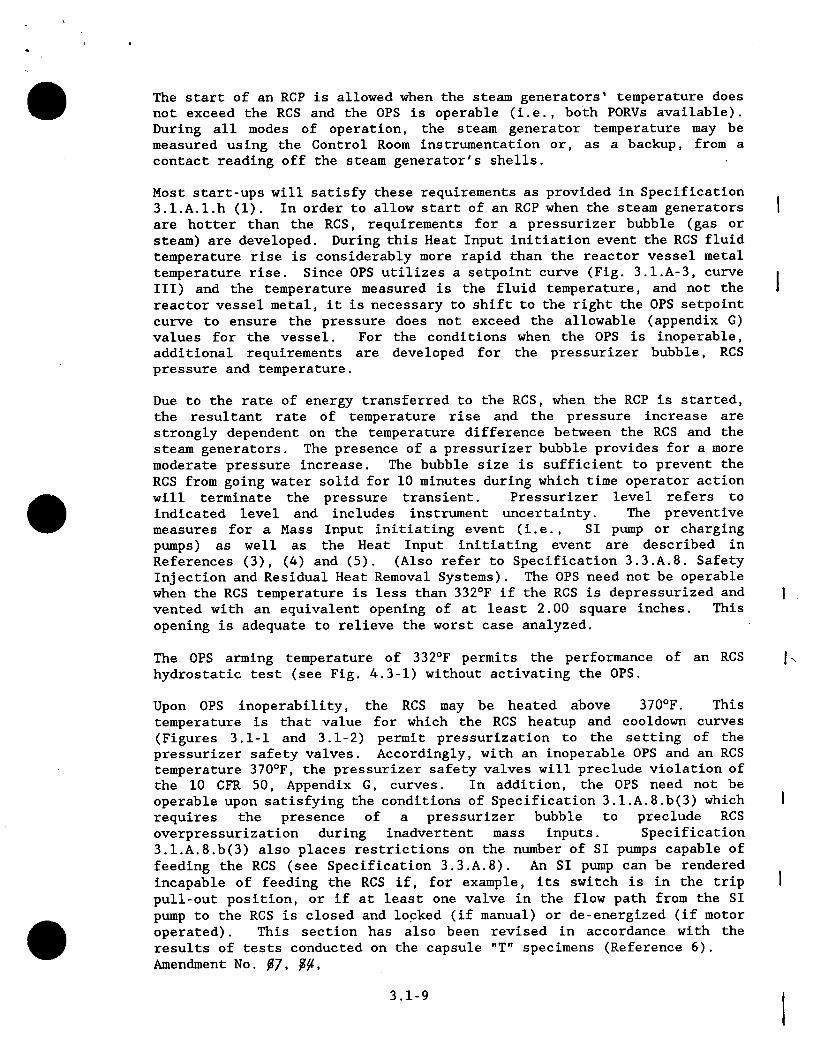
The start of an RCP is allowed when the steam generators' temperature does not exceed the RCS and the OPS is operable (i.e., both PORVs available). During all modes of operation, the steam generator temperature may be measured using the Control Room instrumentation or, as a backup, from a contact reading off the steam generator's shells.
Most start-ups will satisfy these requirements as provided in Specification 3.l.A.l.h (1). In order to allow start of an RCP when the steam generators are hotter than the RCS, requirements for a pressurizer bubble (gas or steam) are developed. During this Heat Input initiation event the RCS fluid temperature rise is considerably more rapid than the reactor vessel metal
temperature rise. Since OPS utilizes a setpoint curve (Fig. 3.1.A-3, curve III) and the temperature measured is the fluid temperature, and not the reactor vessel metal, it is necessary to shift to the right the OPS setpoint curve to ensure the pressure does not exceed the allowable (appendix G)
values for the vessel. For the conditions when the OPS is inoperable, additional requirements are developed for the pressurizer bubble, RCS pressure and temperature.
Due to the rate of energy transferred to the RCS, when the RCP is started, the resultant rate of temperature rise and the pressure increase are strongly dependent on the temperature difference between the RCS and the steam generators. The presence of a pressurizer bubble provides for a more
moderate pressure increase. The bubble size is sufficient to prevent the RCS from going water solid for 10 minutes during which time operator action will terminate the pressure transient. Pressurizer level refers to indicated level and includes instrument uncertainty. The preventive measures for a Mass Input initiating event (i.e., SI pump or charging pumps) as well as the Heat Input initiating event are described in References (3), (4) and (5). (Also refer to Specification 3.3.A.8. Safety Injection and Residual Heat Removal Systems). The OPS need not be operable when the RCS temperature is less than 332 0F if the RCS is depressurized and
vented with an equivalent opening of at least 2.00 square inches. This opening is adequate to relieve the worst case analyzed.
The OPS arming temperature of 332 0F permits the performance of an RCS hydrostatic test (see Fig. 4.3-1) without activating the OPS.
Upon OPS inoperability, the RCS may be heated above 370 0F. This temperature is that value for which the RCS heatup and cooldown curves (Figures 3.1-1 and 3.1-2) permit pressurization to the setting of the pressurizer safety valves. Accordingly, with an inoperable OPS and an RCS temperature 370'F, the pressurizer safety valves will preclude violation of the 10 CFR 50, Appendix G, curves. In addition, the OPS need not be operable upon satisfying the conditions of Specification 3.l.A.8.b(3) which requires the presence of a pressurizer bubble to preclude RCS overpressurization during inadvertent mass inputs. Specification
3.l.A.8.b(3) also places restrictions on the number of SI pumps capable of feeding the RCS (see Specification 3.3.A.8). An SI pump can be rendered
incapable of feeding the RCS if, for example, its switch is in the trip pull-out position, or if at least one valve in the flow path from the SI pump to the RCS is closed and locked (if manual) or de-energized (if motor
operated). This section has also been revised in accordance with the results of tests conducted on the capsule "T" specimens (Reference 6). Amendment No. 07, Y,
3.1-9

References
1) FSAR Section 14.1.6 2) FSAR Section 14.1.8 3) Letter dated 10/25/78 "Summary of Changes to IP-3 Plant Operating
Procedures in Order to Preclude RCS Overpressurization" 4) Letter dated 2/28/76 "Conceptual Design of the Reactor Coolant
Overpressure Protection System" and response to NRC questions. 5) IP-3 Low Temperature Overpressurization Protection System Analysis,
NYPA Report dated 8/24/84. 6) WCAP-9491 "Analysis of Capsule T from IP-3 Reactor Vessel Radiation
Surveillance Program", J.A. Davidson, S.L. Anderson, W.T. Kaiser, April 1979.
Amendment No. 07,
3.1-10

FIGURE 3.1.A- 1 MAXIMUM PERMISSIBLE Tcold FOR FIRST RCP START
(OPS OPERABLE, HOTTEST SG TEMP > Tcold)
350 340 330 320 310 300 290 280 270 260 R An
250 240 QGCD
230 220 210 200 190 180 170 160 150 140 130 120 110 1 0 0 . . . . . . . . . . . . . . . . .. .... .. .. ..... L... .
0 10 20 30 40 50 60 70 80 90 100
(HOTTEST SO TEMP - Tcold) (DEG F)
Amendment No. 07,
3.1-11
LL
0
u

2000 -- Notes: No allowance for instrument error beyond 1OF and 30 psi in Appendix G curve
C3 1750
QL 1500
Q) 1250 Curve I- Hottest SG Temp. less than or equal to - Tcold
H ~5 -- F) I__
_ _ _ _ _ _ _ - -,o - - -.- 0
50750 Q~. _ _ _ _ _ _ _ _ _ ii - 11 h
U)500 - _ _- Curve I-Hottest SG C-)25 I -- ~Temp. up to -64"F higher than Tcold • ry (addition Il pump starts only ! 0 • 0 50 100 150 200 250 300 350 400
Tcold (deg F) Figure 3.1.A-2 Figure applicable toll EFPY
Maximum Permissible RCS Pressure for RCP Start with OPS Inoperable
- Amendment No. 87

2250
-,-2000
(/) 1750 0.
Q)
(I)
(n Q)
0 C,C)
I OUU
1250
1000
750
500
250
0 50 100 150 200 250 3 Tcold (deg F) Figure 3.1 .A--,;3 T d (e
Figure applicable to EFPY
RCS Pressure Limits for Low Temperature Operation Amendment No. A,/,

Maximum PZR Level for Hbttest SG..Termpedture up to 140F higher thani Tc
Notes: No allowdh6 for intrument e'rror beyond 100 F and 30 si ih Appefndix- G and. - PRZR LEVEL (M6ai. Unc.) Figure op licdble to II EFPY PRCS = c Pr essure (Ofsig) Maximum
oldHotteit E up to 64
.PZR Level for ;G Temeroture 'F higher than Tcold
PRCS
... I'll, I - - - 4 j4I -...... -1. i I ij - ' -[1 III T V " T V .
I I' ' _' O l :Ir'j. 1 .1 1_ ],. -. 1 1 -' III I I L I
-I I
00 150 200 250 300 350 100 150 200 250 300 ToId (o F) Tcold (oF)
3. .A-4 Maximum Pressurizer Level for OPS Inoperable and First (Steam Generator Temperature Greater than Tcold)
Amiendment No. Y/,
80
70
80.
70,
-50 JI
il //
PRCS = 400 1
XJA
- 7
j :
4 50 1, A F I I I
... 60
50
S40, 4) 7 N
; 30
2
0 1
Figure Start
L.
30
220
350
RCP

80
0 -J
ci) N
L_
Figure 3.1.A-5 Figure applicable to ll EFPY
MAXIMUM PRESSURIZER LEVEL WITH OPS INOPERABLE AND
ONE (1) CHARGING PUMP ENERGIZED
Amendment No. 07,XW,

35
30-~
25
20"
15
10
5:
0.I 5
45
_-40
I UU Tod 200 250 Tcold (deg F)
Figure 3.1.A-6
NOTES: NO ALLOWANCE FOR INSTRUMENT ERROR OTHER THAN 100 F AND 30 PSI IN- APPENDIX-C CURVE, AND 5% of PRZR% LEVEL (MEAS. UNC.)
- - RCS PRESSURE (PSIG) _ - -_ LS LESS THAN 100
... 7. .,;. - -: _. . .. - l
I&nnj
300 4-I I
350
Figure applicable to 11 EPPY
MAXIMUM PRESSURIZER LEVEL WITH OPS INOPERABLE AND ONE (1)
SAFETY INJECTION PUMP AND/OR THREE (3) CHARGING PUMPS ENERGIZED
Amendment No. ,
42
Q) IJ
U) N
7-3 U) U)
C)
U
500
0/

B. HEATUP AND COOLDOWN
Specifications
1. 'The reactor coolant temperature and pressure and system heatup and cooldown rates averaged over one hour (with the exception of the pressurizer) shall be limited in accordance with Figure 3.1-1 and Figure 3.1-2 for the service period up to 11.00 effective full-power years (EFPYs). The heatup and cooldown rates shall not exceed 601F/hr and 1000F/hr respectively.
a. Allowable combinations of pressure and temperature for specific temperature change rates are below and to the right of the limit lines shown. Limit lines for cooldown rates between those presented may be obtained by interpolation.
2. The limit lines shown in Figure 3.1-1 and Figure 3.1-2 shall be recalculated periodically using methods discussed in the Basis and results of surveillance specimens as covered -in Specification 4.2. The order of specimen removal may be modified based on the results of testing of previously removed specimens.
3. The secondary side of the steam generator shall not be pressurized above 200 psig if the temperature of the steam generator is below 700F.
4. The pressurizer heatup and cooldown rates averaged over one hour shall not exceed 1000F/hr and 200'F/hr, respectively. The spray shall not be used if the temperature difference between the pressurizer and the spray fluid is greater than 320°F.
5. Reactor Coolant System integrity tests shall be performed in accordance with Section 4.3.
Basis
Fracture Toughness Properties
The fracture toughness properties of the ferritic materials in the reactor vessel are determined in accordance with the Summer 1965 Section III of the ASME Boiler and Pressure Vessel Code (6) and ASTM E185 (5) and in accordance with additional reactor vessel requirements. These properties are then evaluated in accordance with Appendix G of the 1972 Summer Addenda to Section III of the ASME Boiler and Pressure Vessel Code (1), and the calculation methods described in WCAP-7924 (2).
Amendment No. 7A, %,
3.1-17

The first reactor vessel material surveillance capsule was removed during the 1978 refueling outage. This capsule has been tested by Westinghouse Corporation and the results have been evaluated and reported (7). Similar reports were prepared for the surveillance capsules (10, 8) removed in 1982 and 1987. Based on the Westinghouse evaluation, heatup and cooldown curves (Figures 3.1-1 and 3.1-2) were developed for up to 11.00 EFPYs of reactor operation.
Generic Letter 88-11 requested that licensees use the methodology of Regulatory Guide 1.99, Revision 2, "Radiation Embrittlement of Reactor Vessel Materials", to predict the effect of neutron radiation on reactor vessel materials as required by paragraph V.A. of 10 CFR part 50, Appendix G. Capsule Z was analyzed (8) and new pressure-temperature curves were developed using this methodology.
The maximum shift in RTNT after 11.00 EFPYs of operation is projected to be 202'F at the 1/4 T and 1630F at the 3/4 T vessel wall locations for Plate B2803-3 the controlling plate. Plate B2803-3 was also the controlling plate for the operating period up to 9.00 EFPYs.
Heatup and cooldown limit curves are calculated using the most limiting value of RTNDT at the end of 11.00 years of service life. The 11.00 year service life period is chosen such that the limiting RTNT at the 1/4 T location in the core region is higher than the RTNDT of the limiting unirradiated material. This service period assures that all components in the Reactor Coolant System will be operated conservatively in accordance with Code recommendations.
The highest RTNT of the core region material is determined by adding the radiation induced ARTNDT for the applicable time period to the original RTNT shown in Table Q4.2-1 (")
Amendment No. 7, 7,
3.1-18

Heatup and Cooldown Curves
Allowable pressure-temperature relationships for various heatup and cooldown rates are calculated using methods derived from Non Mandatory Appendix G in Section III of the ASME Boiler and Pressure Vessel Code and discussed in detail in WCAP-7924. (2)
The approach specifies that the allowable total stress intensity factor (KI) at any time during heatup or cooldown cannot be greater than that shown on the KIR curve (1) for the metal temperature at that time. Furthermore, the approach applies an explicit safety factor of 2.0 on the stress intensity factor induced by pressure gradients. Thus, the governing equation for the heatup-cooldown analysis is:
2 KI+ Krt.KIR (1)
where:
KIm is the stress intensity factor caused by membrane (pressure) stress
Kit is the stress intensity factor caused by the thermal gradients
KIR is provided by the code as a function of temperature relative to the RTNT of the material.
During the heatup analysis, Equation (1) is evaluated for two distinct situations.
First, allowable pressure-temperature relationships are developed for steady state (i.e., zero rate of change of temperature) conditions assuming the presence of the code reference 1/4 T deep flaw at the ID of the pressure vessel. Due to the fact that, during heatup, the thermal gradients in the vessel wall tend to produce compressive stresses at the 1/4 T locations, the tensile stresses induced by internal pressure are somewhat alleviated. Thus, a pressure-temperature curve based on steady state conditions (i.e., no thermal stresses) represents a lower bound of all similar curves for finite heatup rates when the 1/4 T location is treated as the governing factor.
The second portion of the heatup analysis concerns the calculation of pressure temperature limitations for the case in which the 3/4 T location becomes the controlling factor. Unlike the situation at the 1/4 T location, at the 3/4 T position (i.e., the tip of the 1/4 T deep O.D. flaw) the thermal gradients established during heatup produce stresses which are tensile in nature; and, thus, tend to reinforce the pressure stresses present. These thermal stresses are, of course, dependent on both the rate of heatup and the time (or water temperature) along the heatup ramp. Furthermore, since the thermal stresses at 3/4 T are tensile and increase with increasing heatup rate, a lower bound curve similar to that described in the preceding paragraph cannot be defined. Rather, each heatup rate of interest must be analyzed on an individual basis.
Amendment No. %g,
3.1-19

Following the generation of pressure-temperature curves for both the steady state and finite heatup rate situations, the final limit curves are produced in the following fashion. First, a composite curve is constructed based on a point by point comparison of the steady state and finite heatup rate data. At any given temperature, the allowable pressure is taken to be the lesser of the two values taken from the curves under consideration. The composite curve is then adjusted to allow for possible errors in the pressure and temperature sensing instruments.
The use of the composite curve becomes mandatory in setting heatup limitations because it is possible for conditions to exist such that over the course of the heatup ramp the controlling analysis switches from the O.D. to the I.D. location; and the pressure limit must, at all times, be based on the most conservative case.
The cooldown analysis proceeds in the same fashion as that for heatup, with the exception that the controlling location is always at 1/4 T. The thermal gradients induced during cooldown tend to produce tensile stresses at the 1/4 T location and compressive stresses at the 3/4 T position. Thus, the ID flaw is clearly the worst case.
As in the case of heatup, allowable pressure temperature relations are generated for both steady state and finite cooldown rate situations. Composite limit curves are then constructed for each cooldown rate of interest. Again adjustments are made to account for pressure and temperature instrumentation error.
The use of the composite curve in the cooldown analysis is necessary because system control is based on a measurement of reactor coolant temperature, whereas the limiting pressure is calculated using the material temperature at the tip of the assumed reference flaw. During cooldown, the 1/4 T vessel location is at a higher temperature than the fluid adjacent to the vessel I.D. This condition is, of course, not true for the steadystate situation. It follows that the AT induced during cooldown results in a calculated higher allowable KIR for finite cooldown rates than for steady state under certain conditions.
Because operation control is on coolant temperature, and cooldown rate may vary during the cooldown transient, the limit curves shown in Figure 3.1-2 represent a composite curve consisting of the more conservative values calculated for steady state and the specific cooling rate shown.
Details of these calculations are provided in WCAP-7924 [2]. Information on the specific calculations used to develop the current heatup-cooldown curves I can be found in Reference 9.
Amendment No. 7@,
3.1-20

Pressurizer Limits
Although the pressurizer operates at temperature ranges above those for which there is reason for concern about brittle fracture, operating limits are provided to assure compatibility of operation with the fatigue analysis performed in accordance with the ASME -Boiler and Pressure Vessel Code, Section 111, 1965 Edition and associated Code Addenda through the Summer 1966 Addendum.
Amendment No.
3.1-21

REFERENCES
1. ASME Boiler and Pressure Vessel Code, Section III, 1972 Summer
Addenda.
2. WCAP-7924, "Basis for Heatup and Cooldown Limit Curves", W. S.
Hazelton, S. L. Anderson, S. E. Yanichko, July 1972.
3. FSAR Volume 5, Response to Question Q4.2.
4. Intentionally deleted.
5. ASTM E185-70, Surveillance Tests on Structural Materials in Nuclear
Reactors.
6. ASME Boiler and Pressure Vessel Code, Section III, Summer 1965.
7. WCAP-9491, "Analysis of Capsule T from the Indian Point Unit No. 3
Reactor Vessel Radiation Surveillance Program", J. A. Davidson, S. L.
Anderson, W. T. Kaiser, April 1979.
8. WCAP-11815, "Analysis of Capsule Z from the New York Power Authority
Indian Point Unit 3 Reactor Vessel Radiation Surveillance Program," S. E. Yanichko, S. L. Anderson, L. Albertin, March 1988.
9. "Indian Point Unit 3 Final Report on Appendix G Reactor Vessel Pressure - Temperature Limits", ABB Combustion Engineering, July 24,
1990.
10. WCAP-10300-1, Analysis of Capsule Y from the Power Authority of the State of New York Indian Point Unit 3 Reactor Vessel Radiation
Surveillance Program, S.E. Yanichko, S.L. Anderson, March 1983.
Amendment No. 7y, XOP,
3.1-22

FIGURE 3
REACTOR COOLANT SYSTEM HEATUP LIMITATIONS - INDIAN POINT 3
2601
240(
220C
200(
1800
1600
1400
1200
1000
800
600
400
200"
60 80 100 120 140 160 180 200 220. 240 260 280 300 320
T-AVG (DEG F)
MATERIAL PROPERTY BASIS
Amendment No. -, ,
Controlling Material: Plate Metal Copper Content: 0,24 wt, % Phosphorous Content: 0.012 wt. %
- ' : ; I .' ,, :
:11~iCURVE APPLICABLE FOR HEATUPIj SRATES TO 60°F/HR FOR THE 04
MI 7
, , Jt
14 CRE APLIAL FORATS
RATE TO 0° F/HR 60 F/H MARGINS 4F/ ....
fi,!' I f , . . -i
T . ... ... .. [ii
........ II i O F .Tl m -
RT INITIAL: NDTRT AFTER 11 EFPY: NDT 1/4T = 202 F
3/4T = 1630
74 0F
20 F/HR:..
HR
6.0 F/HiR
q q : I : : :
340 360 380
. - .1-11 -- - . - 11

FIGURE 3.1-2
REACTOR COOLANT SYSTEM COOLDOW2500
2000
1500
1 1000
500
0
Material Property Basis: Controlling Material = Plate Metal Copper content = 0.24 wt. % Phosphorous Content = 0.01'2 wt. %
Amendment No. Z$, 0,
- I :v .4.4
RT INITIAL : 740F RT N T AFTER 11 EFPY:
NDT 1/4 T = 202OF 3/4 T = 1630F
ORVESARE PPLICABLE
OR ROLOWN RATES HOWN FOR HE SERVICE ERIOD UP 0 11 EFPY 9D CONTAIN NSTRUMENT RROR MAR£NS OF 10 G F AND )PSIG

C. MINIMUM CONDITIONS FOR CRITICALITY
1. Except during low power physics test, the reactor shall not be made critical at any temperature above which the moderator temperature coefficient is positive.
2. This section intentionally deleted.
3. At all times during critical operation, Tavs should be no lower than 450'F.
4. The reactor shall be maintained subcritical by at least 1% Ak k
until normal water level is established in the pressurizer.
Basis
During the early part of the initial fuel cycle, the moderator temperature coefficient is calculated to be slightly positive at coolant temperatures below the power operating range. (1) (2 ) The moderator coefficient at low temperatures will be most positive at the beginning of life of the fuel cycle, when the boron concentration in the coolant is the greatest. Later in the life of the fuel cycle, the boron concentration in the coolant will be lower and the moderator coefficient will be either less positive or will be negative. At all times, the moderator coefficient is negative in the power operating range.* (1) (2) Suitable physics measurements of moderator coefficient of reactivity will be made as part of the startup program to verify analytic predictions.
The requirement that the reactor is not to be made critical when the moderator coefficient is positive has been imposed to prevent any unexpected power excursion during normal operations as a result of an increase in moderator temperature. This requirement is waived during low power physics tests to permit measurement of reactor moderator coefficient and other physics design parameters of interest. During physics tests, special operating precautions will be taken.
The requirement that the reactor is not to be made critical except when T,,g is > 450OF provides increased assurance that an overpressure event will not occur whenever the reactor vessel is in the nil-ductility temperature range. Heatup to this temperature will be accomplished by operating the reactor coolant pumps.
The requirement for bubble formation in the pressurizer when the reactor has passed the threshold of 1% subcriticality will assure that the reactor coolant not be solid when criticality is achieved.
References:
1. FSAR Table 3.2.1-1
2. FSAR Figure 3.2.1-9
Amendment No. Xg, XPY,
3.1-25

D. Primary Coolant Activity
Specification
1. Whenever the reactor is critical or the average reactor coolant temperature is >500'F, the specific activity of the primary coolant shall be limited to:
a. <1.0 ACi/cc Dose Equivalent 1-131,
and
b. <100/E ACi/cc for all noble gases with half -lives greater than 10 minutes.
2. If the specific activity of the primary coolant is >1.0 IhCi/cc Dose Equivalent 1-131 but within the allowable limit (below and to the left of the line) shown on Figure 3.1-3, operation may continue for up to 48 hours.
3. If the specific acitivity of the primary coolant is >1.0 MCi/cc Dose Equivalent 1-131 for more than 48 hours during one continuous time interval or exceeds the limit line shown on Figure 3.1-3, the reactor shall be immediately brought to the hot shutdown condition with Tavg <500'F utilizing normal operating procedures.
4. If the specific activity of the primary coolant is >100/E ACi/cc for all noble gases with half -lives greater than 10 minutes, the reactor shall be immediately brought to the hot shutdown condition with Tavg :5500OF utilizing normal operating procedures.
Bases
The limitations on the specific activity of the primary coolant insure that the resulting 2-hour doses at the site boundary will not exceed 1.5 rem to the thyroid and 0.5 rem whole body following a steam generator tube rupture accident in conjunction with an assumed steady state primary- to- secondary steam generator leakage rate of 1.0 GPM and a resultant loss of offsite power. Accident meteorological conditions (5% X/Q) are assumed to exist.
The action statement permitting Power Operation to continue for limited time periods with the primary coolant's specific activity >1.0 MCi/cc Dose Equivalent 1-131, but within the allowable limit shown on Figure 3.1-3, accommodates possible iodine spiking phenomenon which may occur following changes in Thermal Power.
Amendment No.
3.1-26I

Reducing Tav& to <5001F prevents the release of activity, should a steam generator tube rupture, since the saturation pressure of the primary coolant is below the lift pressure of the atmospheric steam relief valves. The surveillance requirements provide adequate assurance that excessive specific activity levels in the primary coolant will be detected in sufficient time to take corrective action. Increased surveillance for performing isotopic analyses for iodine is required whenever the Dose Equivalent 1-131 exceeds 1.0 ALCi/cc. and following a significant change in power level to monitor possible iodine spiking phenomenon.
Amendment No. ff,
3.1-27

--3 00
0
L.
:515
0 o
o 200 L_
0
a- 100 I
z
LU
50
o
C/
.0 0
0 020 30 40 50
PERCENT OF60 70 80 90 100
RATED THERMAL POWER
Figure 3.1-3
DOSE EQUIVALENT 1-.131 Primary Coolant Specific Activity Umit Versus Percent of RATED THERMAL POWER with the Primary Coolant Specific Activity > 1 .QCi/gram Dose Equivalent 1-131
Amendment No.3.1-28

E. MAXIMUM REACTOR COOLANT OXYGEN. CHLORIDE AND FLUORIDE CONCENTRATION
Specification
1. Concentrations of contaminants in the reactor shall not exceed the following limits when the reactor coolant is above 250OF:
Normal Steady-State Transient Not To Exceed
Contaminant Operation (PPM) 24 Hours (PPM)
a. Oxygen 0.10 1.00
b. Chloride 0.15 1.50
C. Fluoride 0.15 1.50
2. If any of the normal steady-state operating limits as specified in 3.1.E.1, above, are exceeded, or if it is anticipated that they may be exceeded, corrective action shall be taken immediately.
3. If the concentrations of any of the contaminants cannot be controlled within the limits of Specification 3.1.E.1, namely, steady-state limit not restored within 24 hours or transient limit exceeded, the reactor shall be brought to the cold shutdown condition, utilizing normal operating procedures, and the cause of the out-of-specification operation ascertained and corrected. The reactor may then be restarted and operation resumed if the maximum concentration of any of the contaminants did not exceed the permitted transient values. Otherwise, a safety review is required before startup.
4. Concentrations of contaminants in the reactor coolant shall not exceed the following maximum limits when the reactor coolant temperature is below 250"F:
Normal Concentration Transient Not To Exceed
Contaminant (PPM) 48 Hours (PPM)
a. Oxygen Saturated Saturated
b. Chloride 0.15 1.50
c. Fluoride 0.15 1.50
If the limits above are exceeded, namely, normal concentration limits not restored within 48 hours or the transient limits exceeded, the reactor shall be immediately brought to the cold shutdown condition and the cause of the out-of-specification condition ascertained and corrected.
Amendment No.
3.1-29
. I

5. For the purposes of correcting the contaminant concentrations to meet Specifications 3.1.E.1 and 3.1.E.4 above, increase in coolant temperature consistent with operation of reactor coolant pumps for a short period of time to assure mixing of the coolant shall be permitted. This increase in temperature to assure mixing shall in no case cause the coolant temperature to exceed 2500F.
Basis
By maintaining the oxygen, chloride and fluoride concentrations in the reactor coolant below the limits as specified in 3.1.E.1 and 3.1.E.4, the integrity of the reactor coolant system is assured against stress corrosion cracking under all operating conditions. (1)
If these limits are exceeded, measures can be taken to correct the condition, e.g., replacement of ion exchange resin or adjustment of the hydrogen concentration in the volume control tank (2) during power operation. Because of the time dependent nature of any adverse effects arising from oxygen, chloride, and fluoride concentration in excess of the limits, it is unnecessary to shut down immediately, as the condition-can be corrected. Thus, the periods of either 24 hours or 48 hours for corrective action to restore concentrations within the limits have been established. If the corrective action has not been effective at the end of the proper period (24 hours or 48 hours), then the reactor will be brought to the cold shutdown condition and the corrective action will continue.
The effects of contaminants in the reactor coolant are time and temperature dependent. It is consistent, therefore, to permit a transient concentration to exist for a longer period of time and still provide the assurance that the integrity of the primary coolant system will be maintained.
In order to restore the contaminant concentrations to within specification limits in the event such limits were exceeded, mixing of the primary coolant with the reactor coolant pumps may be required. This will result in a small heatup of short duration and will not increase the average coolant temperature above 250'F.
References
1) FSAR Section 4.2
2) FSAR Section 9.2
Amendment No.
3.1-30

. I
F. LEAKAGE OF REACTOR COOLANT
Specification
1. If leakage of reactor coolant is indicated by the means available such as water inventory balance, monitoring equipment or direct observation a follow-up evaluation of the safety implications shall be initiated as practicable but no later than within 4 hours. Any indicated leak shall be considered to be a real leak until it is determined that the indicated leak cannot be substantiated by direct observation or other indication.
2. If the leakage rate, excluding controlled leakage sources such as the Reactor Coolant Pump Controlled Leakage Seals and Leakage into Closed Systems, exceeds 1 gpm and the source of leakage is not identified, reduce the leakage rate to within limits within four hours or be in hot shutdown within the next six hours and in cold shutdown within the following 30 hours.
3. If the sources of leakage are identified and the results of the evaluation are that continued operation is safe, operation of the reactor with a total leakage, other than from controlled sources or into closed systems, not exceeding 10 gpm shall be permitted except as specified in 3.1.F.4 below.
4. If it is determined that leakage exists through a non- isolable fault which has developed in a Reactor Coolant System Component Body, pipe wall (excluding steam generator tubes), vessel wall or pipe weld, the reactor shall be brought to the cold shutdown condition within twenty- four hours.
5. If the total leakage, other than from controlled sources or into closed systems, exceeds 10 gpm, the reactor shall be placed in the hot shutdown condition within four hours and the cold shutdown condition within an additional twenty-four hours.
6. The reactor shall not be restarted following shutdown as per items 3.1.F.2, 3, 4, or 5, above, until the leak is repaired or until the problem is otherwise corrected.
7. Whenever the reactor is shutdown, or a steam generator removed from service, in order to investigate steam generator tube leakage and/or to plug or otherwise repair a leaking tube, the Authority shall inform the NRC before the reactor is brought critical.
8. Primary to secondary leakage through the steam generator tubes shall be limited to 0.3 gpm (432 gpd) per steam generator and the total leakage through all four steam generators shall be limited to 1.0 gpm (1440 gpd). With any steam generator tube leakage greater than this limit the reactor shall be placed in the hot shutdown condition within four hours and the cold shutdown condition within an additional twenty-four hours.
Amendment No. XY, 74
3.1-31

9. If leakage from two or more tubes in the steam generators in any 20day period is observed or determined, the reactor shall be brought to the hot shutdown condition within four hours and the cold shutdown condition within an additional twenty-four hours and Nuclear Regulatory Commission approval shall be obtained before resuming reactor operation. If two steam generator tube leaks attributable to the tube denting phenomena are observed after the reactor is in cold shutdown Nuclear Regulatory Commission approval shall be obtained before resuming reactor operation.
10. When the reactor is critical and above 2% power, two reactor coolant leak detection systems of different principles capable of detecting leakage into containment shall be in operation, with one of the two systems sensitive to radioactivity. The system sensitive to radioactivity may be out-of -service for 48 hours, provided two other systems are available.
Basis:
Water inventory balances, monitoring equipment, radioactive tracing, boric acid crys5talline- deposits, and physical inspections can disclose reactor coolant leaks. Any leak of radioactive fluid, whether from the reactor coolant system primary boundary or not can be a serious problem with respect to in-plant radioactivity contamination and cleanup or it could develop into a still more serious problem; and therefore, first indications of such leakage will be followed up as soon as practicable.
Although some leak rates on the order of GPM may be tolerable from a dose point of view, it must be recognized that small leaks through any of the walls of the primary system could be indicative of materials failure such as by stress corrosion cracking. If depressurization, isolation and/or other safety measures are not taken promptly, these small leaks could develop into much larger leaks. Therefore, the nature of the leak, as well as the magnitude of the leakage must be considered in the safety evaluation.
The distinction between identified and unidentified leakage in the specification is made because once the leakage source is identified, the seriousness can be easily evaluated. The strict limit of 1 gallon per minute for unidentified leakage is adopted because in the worst case the leakage source may increase with time or the coolant may impinge on or accumulate in a critical component.
Amendment No. ~
3.1-32

When the source of leakage has been identified, the situation can be evaluated to determine if operation can safely continue. This evaluation will be performed by the Watch Force. Under these conditions, an allowable primary system leakage rate of 10 gpm has been established. This explained leakage rate of 10 gpm is also well within the capacity of one charging pump and makeup would be available even under the loss of off-site power condition.
Controlled sources of reactor coolant system leakage are sources which are designed to leak at a controlled rate. For example, the reactor coolant pump seals are controlled leakage sources. Leakage through a valve packing or a closed valve is not considered as controlled leakage. Leakage into closed systems is that leakage which can be accounted for and contained by a system not directly connected to the atmosphere. Leakage past the pressurizer.safety valve seats and steam generator tube leakage are examples of reactor coolant system leakage into closed systems.
If leakage is to the containment, it may be identified by one or more of the following methods:
a.. .The containent air particulate monitor (R-11).
b. The containment radiogas monitor (R-12).
C. The containment humidity detectors.
d. A leakage detection system which determines leakage losses from all water and steam systems within the containment. This system collects and measures moisture condensed from the containment atmosphere by cooling coils of the main air recirculation units.
The most sensitive and rapid method for detecting small amounts of Reactor Coolant System leakage is the monitoring of the containment airborne radioactivity. Containment gaseous and particulate activity is continuously, automatically monitored. The leakage rate can be determined by the relationship of the airborne activity to the reactor coolant activity.
Measurement of the leakage rate to the containment atmosphere is also possible through humidity detection and condensation collection and measurement. However, it is expected that the containment activity method will give the initial indication of coolant leakage. The other methods will be employed primarily to confirm that leakage exists, to indicate the location of the leakage sources, and to measure the leakage rate.
As described above, the four reactor coolant leak detection systems are based on three different principles, i.e., activity, humidity and condensate flow measurements.. Two systems of different principles provide, therefore, diversified ways of detecting leakage to the containment.
Total reactor coolant leakage can be determined by means of periodic water inventory balances. If leakage is into another closed system, it will be detected by the plant radiation monitors and/or inventory control.
Amendment No.
3.1-33

Four hours is allowed from the time of leakage detection to identify the leakage source and to measure the leakage rate. This time period is required since identification and quantification of leakage sources of less than ten gallons per minute require a careful gathering and evaluation of data and/or a visual inspection of the reactor coolant system.
The plant is expected to be operated in a manner such that the secondary coolant will be maintained within those limits found to result in negligible corrosion of the steam generator tubes. If stress corrosion cracking occurs, the extent of cracking during plant operation would be limited by the limitation of steam generator leakage between the primary coolant system and the secondary coolant system. Cracks having a primary-to-secondary leakage less than 500 gallons per day during operation will have an adequate margin of safety against failure due to loads imposed by design basis accidents. The 500 gallon per day per steam generator limit is also consistent with the assumptions used to develop the Technical Specification limit on secondary coolant activity. Operating plants have demonstrated that primary-to-secondary leakage as low as 0.1 gpm will be detected. Leakage in excess of 432 gallons per steam generator or 1 gpm total for all four steam generators will require plant shutdown and an unscheduled eddy
* current-inspection, during which the leaking tubes will be located and plugged.
References
FSAR Sections 11.2.3 and 14.2.4
Amendment No. XY, 7,
3.1-34

G. Secondary Coolant Activity
Specification
1. Whenever the average reactor coolant temperature is > 3500F, the specific
activity of the secondary coolant system shall be < 0.10 gCi/gram of Dose Equivalent 1-131.
2. If the specific activity of the secondary coolant system exceeds 0.10
gCi/gram of Dose Equivalent 1-131, the reactor shall be immediately brought to the hot shutdown condition with Tavg <350'F utilizing normal operating procedures.
Basis
The limitations on secondary system specific activity ensure that the resultant off-site radiation dose will be limited to a small fraction of 10CFR Part 100
limits in the event of a steam line rupture. The restriction of 0.1 MCi/gram Dose Equivalent 1-131 in the secondary system limits the two-hour thyroid exposure dose to 1.5 rem at the site boundary under these accident conditions. This accident analysis also includes the effects of a coincident 500 gallons per day primary to secondary tube leak in the steam generator of the affected steam line and considers the effect of a coincident iodine spike. Accident meteorological conditions are assumed (5% X/Q) and a decontamination factor of 10 is applied between the water and steam phases.
Amendment No.
3.1-35

2) RCS temperature and the source range detectors are monitored hourly;
and
3) no operations are permitted which would reduce the boron concentration of the reactor coolant system.
8. When the RCS cold leg temperature (Tcold) is at or below 332 0F, no more than one safety injection pump shall be energized and aligned to feed the RCS.
B. Containment Cooling and Iodine Removal Systems
1. The reactor shall not be brought above the cold shutdown condition unless the following requirements are met:
a. The spray additive tank contains a minimum of 4000 gallons of solution with a sodium hydroxide concentration of not less than 30% by weight.
b. The five fan cooler-charcoal filter units and the two spray pumps, with their associated valves and piping, are operable.
2. The requirements of 3.3.B.1 may be modified to allow any one of the following components to be inoperable at one time:
3.3-5a
Amendment No. X9, P, 07,

3 , _
4.3 REACTOR COOLANT SYSTEM INTEGRITY TESTING
Applicability
Applies to test requirements for Reactor Coolant System integrity.
Obiective
To specify tests for Reactor Coolant System integrity after the-system-is closed following normal opening, modification or repair.
Specification
a) When the Reactor Coolant System is closed after it has been opened,
the system will be leak tested at not less than 2335 psig and in accordance with NDT requirements for temperature.
b) When Reactor Coolant System modifications or repairs have been made
which involve new strength welds on components, the new welds will
.meet .the.requirements of ASME Section XI.
c) The reactor coolant system leak test temerature-pressure
relationship shall be in accordance with the limits of Figure 4.3-1
for heatup for the first 11.00 EFPYs of operations. Figure 4.3-1 will be recalculated periodically. Allowable pressures during
cooldown from the leak test temperature shall be in accordance with
Figure 3.1-2.
Basis
For normal opening, the integrity of the system, in terms of strength, is
unchanged. If the system does not leak at 2335 psig (Operating pressure
+ 100 psi :± 100 psi is normal system pressure fluctuation), it will be
leak tight during normal operation.
For repairs on components, the thorough non-destructive testing gives a
very high degree of confidence in the integrity of the system, and will
detect any significant defects in and near the new welds. In all cases, the leak test will assure leak tightness during normal operation.
The inservice leak test temperatures are shown on Figure 4.3-1. The
temperatures are calculated in accordance with ASME Code Section III,
Appendix G. This Code requires that a safety factor of 1.5 times the
stress intensity factor caused by pressure be applied to the calculation.
Amendment No. 7, 7, 7,
4.3-1

For the first 11.00 effective full power years, it is predicted that the highest RTNDT in the core region taken at the 1/4 thickness will be 202'F. I The temperature determined by methods of ASME Code Section III for 2335 psig is 133'F above this RTNDT and for 2510 psig (maximum) is 143'F above this RTNT. The minimum inservice leak test temperature requirements for periods up to 11.00 effective full power years are shown on Figure 4.3- I 1(2).
The heatup limits specified on the heatup curve, Figure 4.3-1, must not be exceeded while the reactor coolant system is being heated to the inservice leak test temperature. For cooldown from the leak test temperature, the limitations of Figure 3.1-2 must not be exceeded. Figures 4.3-1 and 3.1-2 are recalculated periodically, using methods discussed in the Basis for Specification 3.1.B and results of surveillance specimens, as covered in Specification 4.2.
Reference
1. FSAR, Section 4.
2. "Indian Point Unit 3 Final Report on Appendix G Reactor Vessel Pressure-Temperature Limits" ABB-Combustion Engineering, July 24, 1990
Amendment No. 7A, 79,
4.3-2

Fig. 4.3-1, PRESSURE/TEMPERATURE
*Iii{iiiI Ii :111 - - - - -~
.. : .. . CURVE APPLICABLE FOR HEATUP
RATES UP TO 60 DEG F/HR FOR THE
... SERVICE PERIOD UP TO 11 EFPY,
AND CONTAINS INSTRUMENT ERROR
MARGINS OF 10 DEG F AND 30 PSIG
* IIi.!!, ,
t t 4 ii I ! 77 77 7 -:'
' iI l 1-i f
H--
t I F~4JT1FtP1TV1iThtT~'t~i11FtTLT ~TtUfl1P ~
- -~ -~h
__L
- - -~- -h - rlilt
2200
2000
1800
1600
1400
1200
1000
60 80 100 120 Amendment No. 0, x,
VTIT 1V71V111717
i]!t
7t-P -7
I , I
II I I f I
0 0
0
H
z
140 160 180 200 220 240 260 280 300 320 340 360
T-avg(deg F)
4--
2600
2400
-F
II 2{Zi800
600
400
200
hIII71171V7 j7F~
w IFUT
; i i I : I ; ; i ; , , i , - : .1 i '17
1ITS FOR HYDROSTATIC LEAK TEST
" I;I A A
1j.

ATTACHMENT 11 TO IPN-91 -040
SAFETY EVALUATION
RELATED TO
PRESSURE-TEMPERATURE AND OVERPRESSURE PROTECTION SYSTEM LI MITS TECHN ICAL SPECI FICATION CHANGES
NEW YORK POWER AUTHORITY I NDIAN POI NT 3 N UCLEAR POWER PLANT
DOCKET NO. 50-286 DPR-64
Attachment II IPN-91-040 Page 1 of 3
Section I - Description of Changes
This application for amendment to the Indian Point 3 Technical Specifications seeks to revise Section 3.1.A (Operational Components), Section 3.1.B (Heatup and Cooldown), Section 3.3 (Engineered Safety Features) and Section 4.3 (Reactor Coolant System Integrity Testing). These sections are being amended to extend the Heatup-Cooldown limits to 11 effective full power years (EFPYs) and to provide for the corresponding Overpressure Protection System (OPS) limits.
Reference 1 transmitted the Authority's request to amend the Heatup-Cooldown limits in accordance with the requirements of Reference 2. Reference 2 requested that licensees use the methodology of Regulatory Guide (RG) 1.99, Revision 2, "Radiation Embrittlement of Reactor Vessel Materials," to predict the effect of neutron radiation on reactor vessel materials as required by Paragraph V.A. of 10 CFR Part 50 Appendix G. The revisions in this amendment are based on data contained in Reference 3 which was submitted with Reference 1.
Specifically, this amendment provides heatup and cooldown pressure-temperature curves which are effective up to 11 EFPYs, and increases the OPS arming (enable) temperature to 3320 F.
In addition to the technical changes, the affected sections are being amended to implement pagination and format changes that constitute human factors improvements to these sections and correct typographical errors.
Specifically, these include pagination changes that were done to remove an unwieldy page numbering system which had evolved over the course of repeated amendments that affected only parts of this section. Additionally, a format change was made to clearly define the tabular data on old pages 3.1-18 and 3.1-19 (new: 3.1-28) and to remove paragraph B.1.b on old page 3.1-4 (new: 3.1-17) which was superfluous and added no substantive content to the specification. The last two changes are made as part of a continuing effort to improve the human factors of the Technical Specifications. The remainder of the changes are typographical.
Section II - Evaluation of Changes
Generic Letter 88-11 requested that licensees use the methodology of RG 1.99, Revision 2, "Radiation Embrittlement of Reactor Vessel Materials," to predict the effect of neutron radiation on reactor vessel material. In accordance with the requirements of RG 1.99, Revision 2, and in keeping with the methodologies described therein, a series of heatup and cooldown curves have been developed for Indian Point 3. The heatup curves cover a range of heatup rates from 20 °F/hr through 60 °F/hr, and the cooldown curves a range from 0 °F/hr (isothermal) to 100 OF/hr.
The calculations supporting these curves incorporate data from analysis of Indian Point 3 surveillance capsules T, Y and Z performed in 1979, 1983 and 1988 respectively. Analysis of capsule Z was performed using the guidance provided in RG 1.99, Revision 2, and is described in Reference 4. Reference 3 provides a detailed description of the methods used to prepare these curves. Accordingly, the OPS limits are conservatively adjusted to be consistent with the revised curves.

Attachment II IPN-91-040 Page 2 of 3
Section III - No Significant Hazards Evaluation
,Consistent with the requirements of 10 CFR 50.92, the enclosed application involves no significant hazards based on the following information:
(1) Does the proposed license amendment involve a significant increase in the probability or consequences of an accident previously evaluated?
Response:
Neither the probability nor the consequences of a previously, analyzed accident is increased due to the proposed changes. The adjusted reference temperature of the limiting beltline material was used to correct the pressuretemperature curves to account for irradiation effects. Thus, the operating limits are adjusted to incorporate the initial fracture toughness conservatism present when the reactor vessel was new. The adjusted reference temperature calculations were performed utilizing the guidance contained in RG 1.99, Revision 2. The updated curves provide assurance that brittle fracture of the reactor vessel is prevented. The changes to the OPS limits are conservative and make them consistent with the revised heatup and cooldown curves.
(2) Does the proposed license amendment create the possibility of a new or
different kind of accident from any accident previously evaluated?
Response:
The updated pressure-temperature (P-T) and OPS limits will not create the possibility of a new or different kind of accident. The revised operating limits merely update the existing limits by taking into account the effects of radiation embrittlement, utilizing criteria defined in RG 1.99, Revision 2 and extending the effective period to 11 EFPYs. The updated P-T curves and OPS limits are conservatively adjusted to account for the effect of irradiation on the limiting reactor vessel material.
No change is being made to the way the P-T or the OPS limits provide plant protection. No new modes of operation are involved. Incorporating this amendment does not necessitate physical alteration of the plant.
(3) Does the proposed amendment involve a significant reduction in a margin of
safety?
Response:
The proposed amendment does not involve a significant reduction in the margin of safety. The P-T and OPS operating limits are designed to provide a margin of safety. The required margin is specified in ASME Boiler and Pressure Vessel Code, Section III, Appendix G and 10 CFR 50 Appendix G. The revised curves are based on the latest NRC guidelines along with actual neutron flux/fluence data for the reactor vessel. The new limits retain a margin of safety equivalent to the original margin when the vessel was new and the

Attachment II IPN-91-040 Page 3 of 3
fracture toughness was slightly greater. The new operating limits account for irradiation embrittlement effects, thereby maintaining a conservative margin of safety.
Section IV - Impact of Changes
These changes will not adversely impact the following:
ALARA Program Security and Fire Protection Programs Emergency Plan FSAR or SER Conclusions Overall Plant Operations and the Environment
Section V - Conclusions
The incorporation of these changes: a) will not increase the probability nor the consequences of an accident or malfunction of equipment important to safety as previously evaluated in the Safety Analysis Report; b) will not increase the possibility for an accident or malfunction of a different type than any evaluated previously in the Safety Analysis Report; c) will not reduce the margin of safety as defined in the bases for any Technical Specification; d) does not constitute an unreviewed safety question; and e) involves no significant hazards considerations as defined in 10 CFR 50.92.
Section VI - References 1. IPN-90-046, "Proposed Changes to Technical Specifications Regarding Pressure
Temperature Umits," dated August 31, 1990
2. Generic Letter 88-11, "NRC Position On Radiation Embrittlement Of Reactor Vessel Materials and Its Impact On Plant Operations," dated July 12, 1988.
3. "Final Report On Pressure-Temperature Umits For Indian Point Unit 3 Nuclear Power Plant," dated July 1990.
4. WCAP-11815, "Analysis Of Capsule Z From The New York Power Authority Indian
Point Unit 3 Reactor Vessel Radiation Surveillance Program," dated March 1988.
5. IP-3 Final Safety Analysis Report.
6. IP-3 Safety Evaluation Report.