Embed Size (px)
Citation preview
2
ATTACK DP - Wood gasifying boiler
- Assembly, pre-heating and training of the attendance is perfomed by an assembly technician trained by the manufacturer, who also fills in a document on the installation of the boiler.-During wood gasifying, tar and condensates (acids) are created in the fuel bin. Therefore behind the boiler the mixing appliance regumat must be installed to keep the minimum temperature of return water of 65°C into the boiler. - Operation temperature of water in the boiler must be of 80-90°C.
- The boiler must not be permanently operated with the output lower than 50%.
- When a circulation pump is used, it must be controlled by a separated thermostat in order to keep the prescribed minimum temperature of return water.- Ecological operation of the boiler is during nominal output.- We recommend to install the boiler with storage reservoirs and Regumat which guarantees economy in fuel in 20 to 30% and longer service life of the boiler as well as comfortable attendance.
- If the boiler cannot be attached to the accumulation, we recommend to connect it at least with one equalisation basin with the volume of about 25l for 1 kW of the boiler output. - During the mode with decreased output (summer mode and water heating) it is necessary to star t burning daily.
- Fuel must be used only dried of 12 - 20% moisture content (with a higher moisture content of fuel the output of boiler decreases and its consumption increases) - The choice of the right boiler size, that is its heating output, is a very important condition for economic operation and right function of the boiler. The boiler must be chosen so that its nominal output responds to heat loss of the heated object.
The guarantee does not apply for the boiler if:
- it is operated with wood exceeding 20% moisture content or with fuel not prescribed by the manufacturer.- if a proper mixing appliance Regumat is not installed in the system, which provides for return water the temperature of 65°C.- a functional thermostatic valve (WATTS STS20) is not installed on the cooling circuit of boiler and connected to the source of cooling water.
This appliance is not suitable for using by those persons (including children), whose physical, mental and sense- disability or the lack of skills obstucts the safe operation, if they are not under restraint, or they were not trained by the responsible person for using the appliance. It is necessary to look after the children to assure, that they will not play with the appliance.
3
Content:
2 Important3 Content4 Introduction, general description5 Technical parameters6 Dimensions of the boilers7,8 Control board of ATTACK DP STANDARD, PROFI9 Purpose of use, technical parameters, operational rules10 Warning11 Technical description of DP PROFI12 Overheating of the boiler, the ways of regulation, displaying faults13 Maintenance of heating system, prescribed fuel14 Location of the boiler15 Chimney, exhaust pipe, connecting boiler to the mains, connection to the heating system16 Protection of boiler against corrosion17 Installation and change of the fireproof concrete shaped peaces 18 Variants of connections19 Variants of connections, variants of protection and boiler durability increase20 Operation with the accumulation tanks 21 Protection of boiler against overheating22 Possible faults and the means of their elimination23 Scheme of dependency of resistance on the temperature of heating water by the thermal probe ( DP PROFI )24-27 The schemes ofelectrical connections of ATTACK DP boilers28 Notes
4
Introduction:
Dear customer,
Thank you for confidence that you showed us by purchasing our product - ATTACK wood gasifying boiler. We wish you long and reliable operation. Proper attendance of the boiler is one of the conditions for reliable and right operation, so please read this instruction for use carefully. The manual is written in the way to respect the right operation of the boiler in central heating system.The conditions of right boiler operation:- to choose the right type and output of the boiler- impeccable putting into operation- sensitive attendance- regular technical maintenance- reliable service
General description:
ATTACK DP wood gasifying boiler is designed for economic and ecological heating of family houses, bungalows, small plants, workshops and similar objects.Specified fuel for ATTACK DP boilers is dry wood, e.g. logs of lengths, depending on the type of boiler. The wood gasifying boiler is the holder of 101 5 certificate.
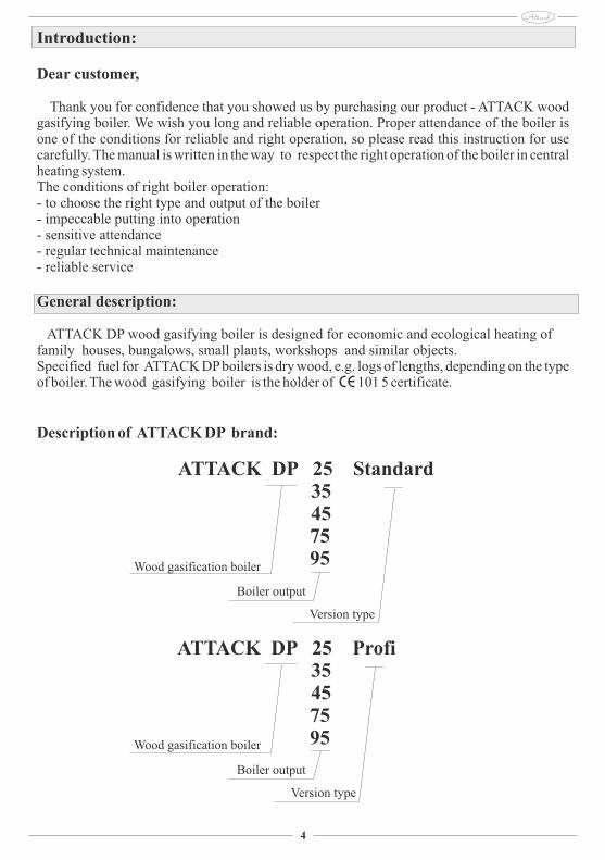
Description of ATTACK DP brand:
ATTACK DP 25 Standard 35 45 75 95
ATTACK DP 25 Profi 35 45 75 95
Boiler output
Wood gasification boiler
Version type
Boiler output
Wood gasification boiler
Version type
5
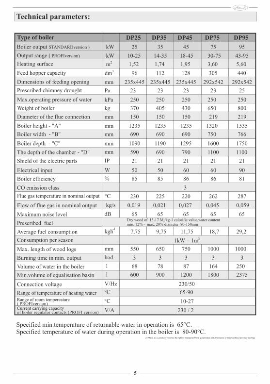
Specified min.temperature of returnable water in operation is 65°C.Specified temperature of water during operation in the boiler is 80-90°C.
Technical parameters:
ATTACK, s.r.o. producer reserves the right to change technical parameters and dimensions of boilers without previous warning.
DP25 DP35 DP45 DP75 DP95
25 35 45 75 95
10-25 14-35 18-45 30-75 43-95
1,52 1,74 1,95 3,60 5,60
96 112 128 305 440
235x445 235x445 235x445 292x542 292x542
23 23 23 23 25
250 250 250 250 250
370 405 430 650 800
150 150 150 219 219
1235 1235 1235 1320 1535
690 690 690 750 766
1090 1190 1295 1600 1750
590 690 790 1100 1100
21 21 21 21 21 50 50 60 60 90 85 85 86 86 81
3
230 225 220 262 287 0,019 0,021 0,027 0,045 0,059
65 65 65 65 65
7,75 9,75 11,75 18,7 29,2
550 650 750 1000 1000 3 3 3 3 3
68 78 87 164 250
600 900 1200 1800 2375
230/50
3 1kW = 1m
65-90
10-27
230 / 2
kW
kW
2 m
3 dm
mm
Pa
kPa
kg
mm
mm
mm
mm
IP W
%
°C kg/s
dB -1 kgh
mm hod.
l
l
V/Hz °C
°C
V/A
mm
Type of boiler Boiler output STANDARDversion )
Output range ( PROFIversion)
Heating surface
Feed hopper capacity
Dimensions of feeding opening
Prescribed chimney drought
Max.operating pressure of water
Weight of boiler
Diameter of the flue connection
Boiler height - "A" Boiler width - "B"
Boiler depth - "C"
The depth of the chamber - "D" Shield of the electric parts Electrical input
Boiler efficiency
CO emission class
Flue gas temperature in nominal output Flow of flue gas in nominal output
Maximum noise level Prescribed fuel
Average fuel consumption
Max. length of wood logs Burning time in min. output
Volume of water in the boiler
Range of temperature of heating water
Min.volume of equalisation basin
Connection voltage
Consumption per season
Range of room tempereature ( PROFIversion)
Current carrying capacity of boiler regulator contacts (PROFI version)
Dry wood of 15-17 Mj/kg-1 calorific value,water contentmin. 12% - max. 20% diameter 80-150mm
6
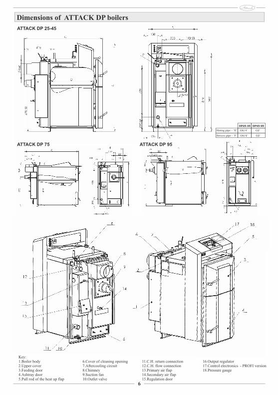
Dimensions of ATTACK DP boilers
Key:1. Boiler body2. Upper cover3. Feeding door4. Ashtray door5. Pull rod of the heat up flap
6. Cover of cleaning opening7. Aftercooling circuit8. Chimney9. Suction fan10. Outlet valve
11. C.H. return connection12. C.H. flow connection13. Primary air flap14. Secondary air flap15. Regulation door
16. Output regulator17. Control electronics - PROFI version18. Pressure gauge
ATTACK DP 25-45
ATTACK DP 75 ATTACK DP 95
DP25-35 DP45-95
G6/4" G2"
G6/4" G2"
Rising pipe - "E"
Return pipe - "F"
11
Required boiler temperature [C 80] - is temperature that the regulator tries to reach in the operation mode. It is set by direct turning of button of the boiler thermostat and it is indicated by short displaying.Set temperature of the flue gas / room thermostat [100C] - this parameter indicates temperature set by additional flue gas / room thermostat. In accordance to installation of heating and setting of parameter FC (1 or 0) it represents the flue gas temperature (at lower actual temperature, the regulator switches into the fuel shortage mode) or the room temperature.Actual flue gas temperature or room temperature [180°] - this parameter indicates actually measured flue gas temperature or room temperature.
Setting of parameters – service menu
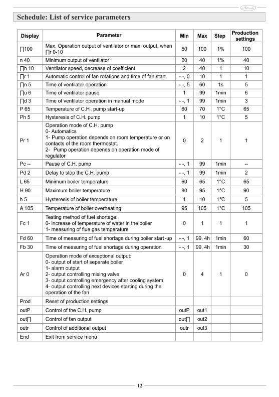
When the OK button is held for longer than 3 seconds, it is switched to the service mode, where you can see and change programmed parameters. Service mode is indicated by flickering of the additional thermostat´s control light. It is possible to browse parameters by the + and - buttons. After selection of the required parameter you can switch into the mode for parameter change by pressing of the OK button - this mode is indicated by flickering of the parameter value. To change the value, use the + and - button. New setting can be confirmed by the OK button. Then it is possible to select next parameter (by + and -). If you wish to close service mode, select [END] by + and - and press OK or wait for 1 minute. Devices finishes service mode and starts to display boiler temperature.First column in the schedule represents display indications and in the next columns are: parameter description, minimum value, maximum permitted value of setting, step of parameter setting during adjustment, production settings to which it is possible to come by selecting of the [Prod] option..
12
Display Parameter Min Max StepProduction
settings
∏100Max. Operation output of ventilator or max. output, when∏r 0-10
50 100 1% 100
n 40 Minimum output of ventilator
20
40
1%
40
∏h 10 Ventilator speed, decrease of coefficient
2
40
1
10
∏r 1 Automatic control of fan rotations and time of fan start
-
-, 0
10
1
1
∏n 5 Time of ventilator operation
-
-, 5
60
1s
5
∏u 6 Time of ventilator pause
1
99
1min
6
∏d 3 Time of ventilator operation in manual mode
-
-, 1
99
1min
3
P 65 Temperature of C.H . pump start-up
60
70
1°C
65
Ph 5 Hysteresis
of C.H. pump
1
10
1°C
5
Pr 1
Operation mode of C.H. pump
0-
Automatics
1-
Pump operation depends on room temperature or on contacts of the room thermostat.
2-
Pump operation depends on operation mode of regulator
0
2
1
1
Pc -- Pause of C.H. pump
-
-, 1
99
1min
--
Pd 2 Delay to stop the C.H. pump
-
-, 1
99
1min
2
L 65 Minimum boiler temperature 60 65 1°C 65
H 90 Maximum boiler temperature 80 95 1°C 90
h 5 Hysteresis
of boiler temperature
1 10
1°C
5
A 105 Temperature of boiler overheating
95
105
1°C
105
Fc 1Testing method of fuel shortage:
0-
increase of temperature of water in the boiler
1-
measuring of flue gas temperature
0
1
1
1
Fd 60 Time of measuring of fuel shortage during boiler start -up
-
-,
1
99, 4h
1min
60
Fb 30 Time of measuring of fuel shortage during operation
-
-, 1
99, 4h
1min
30
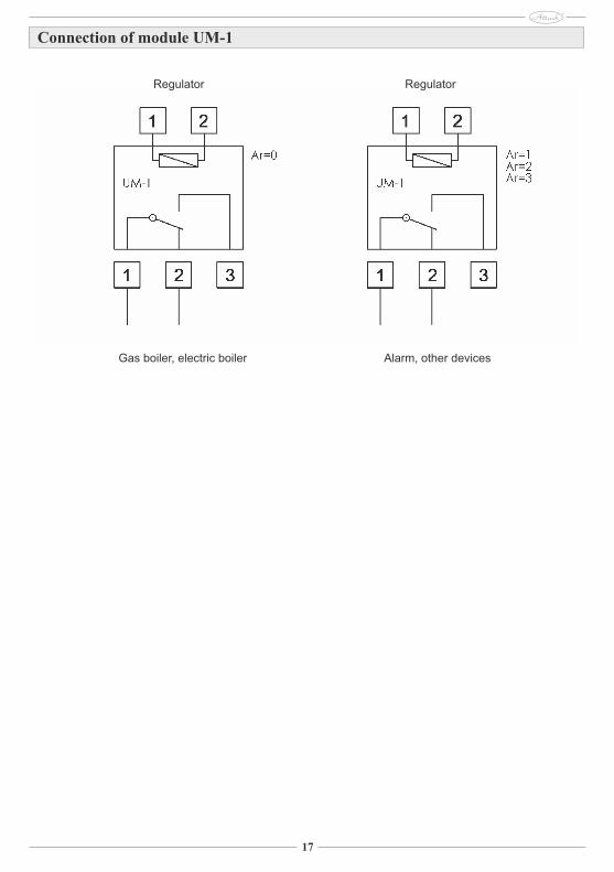
Ar 0
Operation mode of exceptional output:
0-
output of start of separate boiler
1-
alarm output
2-
output controlling mixing valve
3-
output controlling emergency after cooling
system
4-
output controlling next devices starting during the operation of the fan
0
4
1
0
Prod Reset of production settings
outP Control of the C.H. pump outP out1
out∏ Control of fan output out∏ out2
outr Control of additional output outr out3
End Exit from service menu
Schedule: List of service parameters
13
Operation parameters of flue gas fan
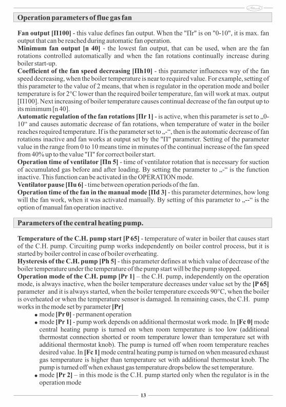
Fan output [Π100] - this value defines fan output. When the "Πr" is on "0-10", it is max. fan output that can be reached during automatic fan operation. Minimum fan output [n 40] - the lowest fan output, that can be used, when are the fan rotations controlled automatically and when the fan rotations continually increase during boiler start-up. Coefficient of the fan speed decreasing [Πh10] - this parameter influences way of the fan speed decreasing, when the boiler temperature is near to required value. For example, setting of this parameter to the value of 2 means, that when is regulator in the operation mode and boiler temperature is for 2°C lower than the required boiler temperature, fan will work at max. output [Π100]. Next increasing of boiler temperature causes continual decrease of the fan output up to its minimum [n 40].Automatic regulation of the fan rotations [Πr 1] - is active, when this parameter is set to „0-10“ and causes automatic decrease of fan rotations, when temperature of water in the boiler reaches required temperature. If is the parameter set to „-“, then is the automatic decrease of fan rotations inactive and fan works at output set by the "Π" parameter. Setting of the parameter value in the range from 0 to 10 means time in minutes of the continual increase of the fan speed from 40% up to the value "Π" for correct boiler start.Operation time of ventilator [Πn 5] - time of ventilator rotation that is necessary for suction of accumulated gas before and after loading. By setting the parameter to „-“ is the function inactive. This function can be activated in the OPERATION mode. Ventilator pause [Πu 6] - time between operation periods of the fan.Operation time of the fan in the manual mode [Πd 3] - this parameter determines, how long will the fan work, when it was activated manually. By setting of this parameter to „--“ is the option of manual fan operation inactive.
Parameters of the central heating pump.
Temperature of the C.H. pump start [P 65] - temperature of water in boiler that causes start of the C.H. pump. Circuiting pump works independently on boiler control process, but it is started by boiler control in case of boiler overheating.Hysteresis of the C.H. pump [Ph 5] - this parameter defines at which value of decrease of the boiler temperature under the temperature of the pump start will be the pump stopped.Operation mode of the C.H. pump [Pr 1] – the C.H. pump, independently on the operation mode, is always inactive, when the boiler temperature decreases under value set by the [P 65] parameter and it is always started, when the boiler temperature exceeds 90°C, when the boiler is overheated or when the temperature sensor is damaged. In remaining cases, the C.H. pump works in the mode set by parameter [Pr]
mode [Pr 0] - permanent operation mode [Pr 1] - pump work depends on additional thermostat work mode. In [Fc 0] mode
central heating pump is turned on when room temperature is too low (additional thermostat connection shorted or room temperature lower than temperature set with additional thermostat knob). The pump is turned off when room temperature reaches desired value. In [Fc 1] mode central heating pump is turned on when measured exhaust gas temperature is higher than temperature set with additional thermostat knob. The pump is turned off when exhaust gas temperature drops below the set temperature.
mode [Pr 2] – in this mode is the C.H. pump started only when the regulator is in the operation mode
14
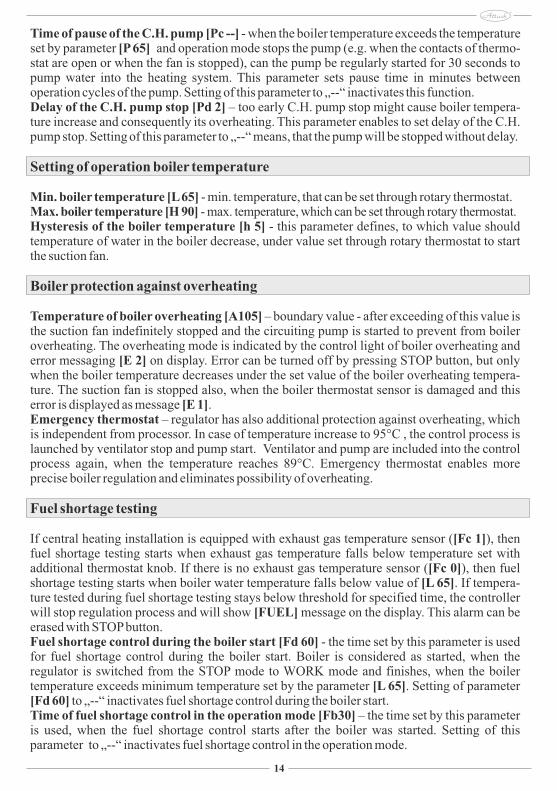
Time of pause of the C.H. pump [Pc --] - when the boiler temperature exceeds the temperature set by parameter [P 65] and operation mode stops the pump (e.g. when the contacts of thermo-stat are open or when the fan is stopped), can the pump be regularly started for 30 seconds to pump water into the heating system. This parameter sets pause time in minutes between operation cycles of the pump. Setting of this parameter to „--“ inactivates this function.Delay of the C.H. pump stop [Pd 2] – too early C.H. pump stop might cause boiler tempera-ture increase and consequently its overheating. This parameter enables to set delay of the C.H. pump stop. Setting of this parameter to „--“ means, that the pump will be stopped without delay.
Setting of operation boiler temperature
Min. boiler temperature [L 65] - min. temperature, that can be set through rotary thermostat.Max. boiler temperature [H 90] - max. temperature, which can be set through rotary thermostat. Hysteresis of the boiler temperature [h 5] - this parameter defines, to which value should temperature of water in the boiler decrease, under value set through rotary thermostat to start the suction fan.
Boiler protection against overheating
Temperature of boiler overheating [A105] – boundary value - after exceeding of this value is the suction fan indefinitely stopped and the circuiting pump is started to prevent from boiler overheating. The overheating mode is indicated by the control light of boiler overheating and error messaging [E 2] on display. Error can be turned off by pressing STOP button, but only when the boiler temperature decreases under the set value of the boiler overheating tempera-ture. The suction fan is stopped also, when the boiler thermostat sensor is damaged and this error is displayed as message [E 1].Emergency thermostat – regulator has also additional protection against overheating, which is independent from processor. In case of temperature increase to 95°C , the control process is launched by ventilator stop and pump start. Ventilator and pump are included into the control process again, when the temperature reaches 89°C. Emergency thermostat enables more precise boiler regulation and eliminates possibility of overheating.
Fuel shortage testing
If central heating installation is equipped with exhaust gas temperature sensor ([Fc 1]), then fuel shortage testing starts when exhaust gas temperature falls below temperature set with additional thermostat knob. If there is no exhaust gas temperature sensor ([Fc 0]), then fuel shortage testing starts when boiler water temperature falls below value of [L 65]. If tempera-ture tested during fuel shortage testing stays below threshold for specified time, the controller will stop regulation process and will show [FUEL] message on the display. This alarm can be erased with STOP button. Fuel shortage control during the boiler start [Fd 60] - the time set by this parameter is used for fuel shortage control during the boiler start. Boiler is considered as started, when the regulator is switched from the STOP mode to WORK mode and finishes, when the boiler temperature exceeds minimum temperature set by the parameter [L 65]. Setting of parameter [Fd 60] to „--“ inactivates fuel shortage control during the boiler start.Time of fuel shortage control in the operation mode [Fb30] – the time set by this parameter is used, when the fuel shortage control starts after the boiler was started. Setting of this parameter to „--“ inactivates fuel shortage control in the operation mode.
15
Additional output.
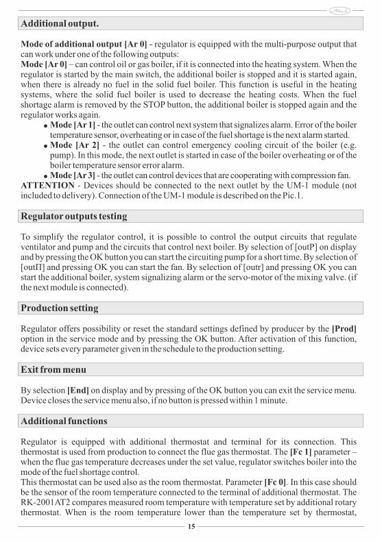
Mode of additional output [Ar 0] - regulator is equipped with the multi-purpose output that can work under one of the following outputs:Mode [Ar 0] – can control oil or gas boiler, if it is connected into the heating system. When the regulator is started by the main switch, the additional boiler is stopped and it is started again, when there is already no fuel in the solid fuel boiler. This function is useful in the heating systems, where the solid fuel boiler is used to decrease the heating costs. When the fuel shortage alarm is removed by the STOP button, the additional boiler is stopped again and the regulator works again.
Mode [Ar 1] - the outlet can control next system that signalizes alarm. Error of the boiler temperature sensor, overheating or in case of the fuel shortage is the next alarm started.
Mode [Ar 2] - the outlet can control emergency cooling circuit of the boiler (e.g. pump). In this mode, the next outlet is started in case of the boiler overheating or of the boiler temperature sensor error alarm.
Mode [Ar 3] - the outlet can control devices that are cooperating with compression fan.ATTENTION - Devices should be connected to the next outlet by the UM-1 module (not included to delivery). Connection of the UM-1 module is described on the Pic.1.
Regulator outputs testing
To simplify the regulator control, it is possible to control the output circuits that regulate ventilator and pump and the circuits that control next boiler. By selection of [outP] on display and by pressing the OK button you can start the circuiting pump for a short time. By selection of [outΠ] and pressing OK you can start the fan. By selection of [outr] and pressing OK you can start the additional boiler, system signalizing alarm or the servo-motor of the mixing valve. (if the next module is connected).
Production setting
Regulator offers possibility or reset the standard settings defined by producer by the [Prod] option in the service mode and by pressing the OK button. After activation of this function, device sets every parameter given in the schedule to the production setting.
Exit from menu
By selection [End] on display and by pressing of the OK button you can exit the service menu. Device closes the service menu also, if no button is pressed within 1 minute.
Additional functions
Regulator is equipped with additional thermostat and terminal for its connection. This thermostat is used from production to connect the flue gas thermostat. The [Fc 1] parameter – when the flue gas temperature decreases under the set value, regulator switches boiler into the mode of the fuel shortage control.This thermostat can be used also as the room thermostat. Parameter [Fc 0]. In this case should be the sensor of the room temperature connected to the terminal of additional thermostat. The RK-2001AT2 compares measured room temperature with temperature set by additional rotary thermostat. When is the room temperature lower than the temperature set by thermostat,
16
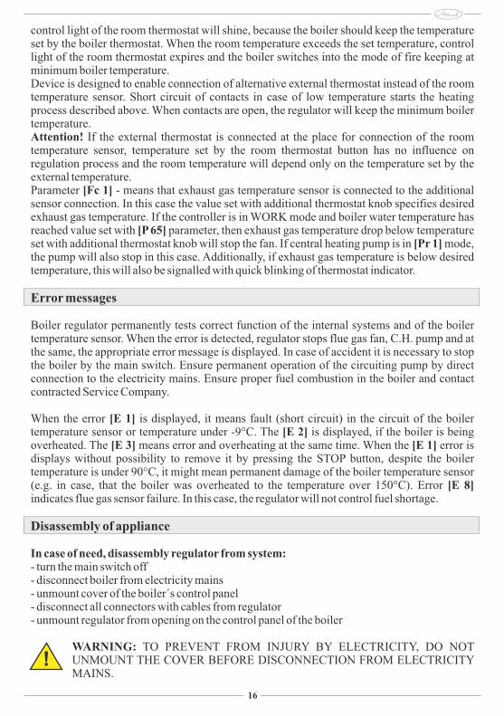
control light of the room thermostat will shine, because the boiler should keep the temperature set by the boiler thermostat. When the room temperature exceeds the set temperature, control light of the room thermostat expires and the boiler switches into the mode of fire keeping at minimum boiler temperature. Device is designed to enable connection of alternative external thermostat instead of the room temperature sensor. Short circuit of contacts in case of low temperature starts the heating process described above. When contacts are open, the regulator will keep the minimum boiler temperature.Attention! If the external thermostat is connected at the place for connection of the room temperature sensor, temperature set by the room thermostat button has no influence on regulation process and the room temperature will depend only on the temperature set by the external temperature.Parameter [Fc 1] - means that exhaust gas temperature sensor is connected to the additional sensor connection. In this case the value set with additional thermostat knob specifies desired exhaust gas temperature. If the controller is in WORK mode and boiler water temperature has reached value set with [P 65] parameter, then exhaust gas temperature drop below temperature set with additional thermostat knob will stop the fan. If central heating pump is in [Pr 1] mode, the pump will also stop in this case. Additionally, if exhaust gas temperature is below desired temperature, this will also be signalled with quick blinking of thermostat indicator.
Error messages
Boiler regulator permanently tests correct function of the internal systems and of the boiler temperature sensor. When the error is detected, regulator stops flue gas fan, C.H. pump and at the same, the appropriate error message is displayed. In case of accident it is necessary to stop the boiler by the main switch. Ensure permanent operation of the circuiting pump by direct connection to the electricity mains. Ensure proper fuel combustion in the boiler and contact contracted Service Company.
When the error [E 1] is displayed, it means fault (short circuit) in the circuit of the boiler temperature sensor or temperature under -9°C. The [E 2] is displayed, if the boiler is being overheated. The [E 3] means error and overheating at the same time. When the [E 1] error is displays without possibility to remove it by pressing the STOP button, despite the boiler temperature is under 90°C, it might mean permanent damage of the boiler temperature sensor (e.g. in case, that the boiler was overheated to the temperature over 150°C). Error [E 8] indicates flue gas sensor failure. In this case, the regulator will not control fuel shortage.
Disassembly of appliance
In case of need, disassembly regulator from system:- turn the main switch off- disconnect boiler from electricity mains- unmount cover of the boiler´s control panel- disconnect all connectors with cables from regulator- unmount regulator from opening on the control panel of the boiler
WARNING: TO PREVENT FROM INJURY BY ELECTRICITY, DO NOT UNMOUNT THE COVER BEFORE DISCONNECTION FROM ELECTRICITY MAINS.
!
17
Connection of module UM-1
Regulator Regulator
Gas boiler, electric boiler Alarm, other devices
18
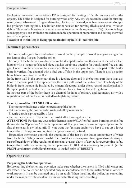
Purpose of use
Ecological hot-water boiler Attack DP is designed for heating of family houses and similar objects. The boiler is designed for burning wood only. Any dry wood can be used for burning, mainly logs. Also wood of bigger diameter, blocks, can be used, which reduces nominal output but prolongs burning time. The boiler cannot be used for burning filedust and small wooden debris. This can be burnt only in small amount together with logs (max. 10%). Due to its large feed hopper you can avoid the most demandable operation of preparation and cutting the wood into smaller pieces.Location of the boilers in living spaces (including halls) is inadmissible!
Technical parameters
The boiler is designed for combustion of wood on the principle of wood gasifying using a flue gas fan sucking flue gas from the boiler.The body of the boiler is a weldment of metal steel plates of 6 mm thickness. It includes a feed hopper with a heatproof shaped piece that has an oblong opening for transition of flue gas and gas. Under it in the after-combustion space there is an ash pan. In the rear part of the boiler there is vertical flue channel with a fuel cut-off flap in the upper part. There is also a suction branch for connection to the flue. In the front wall in the upper part there is a feeding door and in the bottom part there is an ash door.In the front part of the upper cover there is a pull rod of fuel cut-off flap. The body of the boiler is from the outside insulated by mineral fleece put under the covers of outside jacket.In the upper part of the boiler there is a control board for electromechanical regulation. .In the rear part of the boiler there is a channel for inlet of primary and secondary air with a regulation flap where the air is heated to a high temperature.
Description of the STANDARD version- Thermometer indicates outlet temperature of the boiler- If it is necessary, the boiler can be switched off by main switch- Electric circuit is protected by a fuse- Fan can be switched off by a flue thermostat after burning down fuel.ATTENTION! For heating up, set this thermostat to 0°C. After fuel starts burning, set the flue thermostat to "Operation".If the temperature of flue gas drops below set up temperature the flue thermostat is switched off. If you want the fan start again, you have to set up a lower temperature.The optimum condition for operation must be tried.- Regulation thermostat controls the operation of the fan by the outlet temperature of water from the boiler. Safety non-returnable thermostat serves as a protection against overheating in case of breakdown of the regulation thermostat or as an alarm of device for overcoming safety temperature. (in the After overcoming the temperature of 110°C it is necessary to press it.PROFI version turn the boiler thermostat to the left point of "RESET")
Operation rules
Preparing the boiler for operationBefore putting the boiler into operation make sure whether the system is filled with water and deareated. The boiler can be operated only in accordance with these instructions in order to work properly. It can be operated only by an adult. When installing the boiler, lay something under the rear part to elevate it in 10 mm for better flushing and deareating.
23
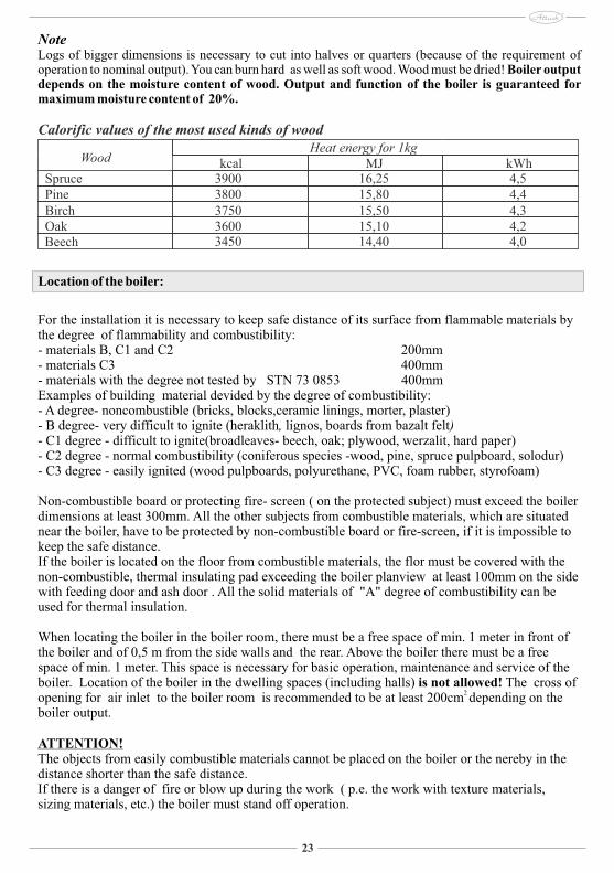
NoteLogs of bigger dimensions is necessary to cut into halves or quarters (because of the requirement of operation to nominal output). You can burn hard as well as soft wood. Wood must be dried! Boiler output depends on the moisture content of wood. Output and function of the boiler is guaranteed for maximum moisture content of 20%.
Location of the boiler:
For the installation it is necessary to keep safe distance of its surface from flammable materials by the degree of flammability and combustibility: - materials B, C1 and C2 200mm- materials C3 400mm- materials with the degree not tested by STN 73 0853 400mmExamples of building material devided by the degree of combustibility:- A degree- noncombustible (bricks, blocks,ceramic linings, morter, plaster)- B degree- very difficult to ignite (heraklith, lignos, boards from bazalt felt)- C1 degree - difficult to ignite(broadleaves- beech, oak; plywood, werzalit, hard paper) - C2 degree - normal combustibility (coniferous species -wood, pine, spruce pulpboard, solodur)- C3 degree - easily ignited (wood pulpboards, polyurethane, PVC, foam rubber, styrofoam)
Non-combustible board or protecting fire- screen ( on the protected subject) must exceed the boiler dimensions at least 300mm. All the other subjects from combustible materials, which are situated near the boiler, have to be protected by non-combustible board or fire-screen, if it is impossible to keep the safe distance. If the boiler is located on the floor from combustible materials, the flor must be covered with the non-combustible, thermal insulating pad exceeding the boiler planview at least 100mm on the side with feeding door and ash door . All the solid materials of "A" degree of combustibility can be used for thermal insulation.
When locating the boiler in the boiler room, there must be a free space of min. 1 meter in front of the boiler and of 0,5 m from the side walls and the rear. Above the boiler there must be a free space of min. 1 meter. This space is necessary for basic operation, maintenance and service of the boiler. Location of the boiler in the dwelling spaces (including halls) is not allowed! The cross of
2 opening for air inlet to the boiler room is recommended to be at least 200cm depending on the boiler output.
ATTENTION!The objects from easily combustible materials cannot be placed on the boiler or the nereby in the distance shorter than the safe distance. If there is a danger of fire or blow up during the work ( p.e. the work with texture materials, sizing materials, etc.) the boiler must stand off operation.
Calorific values of the most used kinds of woodHeat energy for 1kg
Wood
SprucePineBirchOakBeech
kcal MJ kWh39003800375036003450
16,2515,8015,5015,1014,40
4,54,44,34,24,0
24
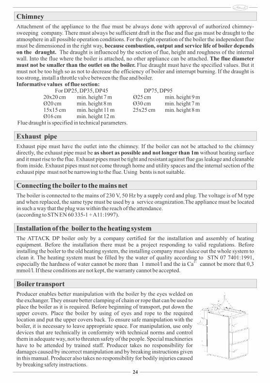
Chimney
Attachment of the appliance to the flue must be always done with approval of authorized chimney-sweeping company. There must always be sufficient draft in the flue and flue gas must be draught to the atmosphere in all possible operation conditions. For the right operation of the boiler the independent flue must be dimensioned in the right way, because combustion, output and service life of boiler depends on the draught. The draught is influenced by the section of flue, height and roughness of the internal wall. Into the flue where the boiler is attached, no other appliance can be attached. The flue diameter must not be smaller than the outlet on the boiler. Flue draught must have the specified values. But it must not be too high so as not to decrease the efficiency of boiler and interrupt burning. If the draught is too strong, install a throttle valve between the flue and boiler.Informative values of flue section: �������� For DP25, DP35, DP45 DP75, DP95 20x20 cm min. height 7 m Ø25 cm min. height 9 m Ø20 cm min. height 8 m Ø30 cm min. height 7 m 15x15 cm min. height 11 m 25x25 cm min. height 8 m Ø16 cm min. height 12 m Flue draught is specified in technical parameters.
Exhaust pipe
Exhaust pipe must have the outlet into the chimney. If the boiler can not be attached to the chimney directly, the exhaust pipe must be as short as possible and not longer than 1m without heating surface and it must rise to the flue. Exhaust pipes must be tight and resistant against flue gas leakage and cleanable from inside. Exhaust pipes must not come through home and utility spaces and the internal section of the exhaust pipe must not be narrowing to the flue. Using bents is not suitable.
Connecting the boiler to the mains net
The boiler is connected to the mains of 230 V, 50 Hz by a supply cord and plug. The voltage is of M type and when replaced, the same type must be used by a service oragnization.The appliance must be located in such a way that the plug was within the reach of the attendance.(according to STN EN 60 335-1 + A11:1997).
Installation of the boiler to the heating system
The ATTACK DP boiler only by a company certified for the installation and assembly of heating equipment. Before the installation there must be a project responding to valid regulations. Before installing the boiler to the old heating system, the installing company must sluice out the whole system to clean it. The heating system must be filled by the water of quality according to STN 07 7401:1991,
2+especially the hardness of water cannot be more than 1 mmol/l and the ia Ca cannot be more that 0,3 mmol/l. If these conditions are not kept, the warranty cannot be accepted.
Boiler transport
Producer enables better manipulation with the boiler by the eyes welded on the exchanger. They ensure better clamping of chain or rope that can be used to place the boiler as it is required. Before beginning of transport, put down the upper covers. Place the boiler by using of eyes and rope to the required location and put the upper covers back. To ensure safe manipulation with the boiler, it is necessary to leave appropriate space. For manipulation, use only devices that are technically in conformity with technical norms and control them in adequate way, not to threaten safety of the people. Special machineries have to be attended by trained staff. Producer takes no responsibility for damages caused by incorrect manipulation and by breaking instructions given in this manual. Producer also takes no responsibility for bodily injuries caused by breaking safety instructions.
25
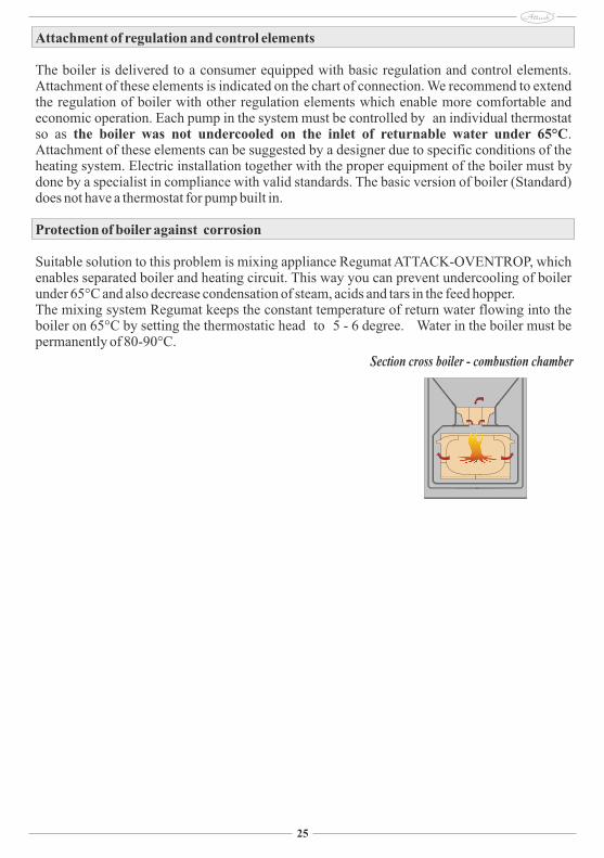
Section cross boiler - combustion chamber
Attachment of regulation and control elements
The boiler is delivered to a consumer equipped with basic regulation and control elements. Attachment of these elements is indicated on the chart of connection. We recommend to extend the regulation of boiler with other regulation elements which enable more comfortable and economic operation. Each pump in the system must be controlled by an individual thermostat so as the boiler was not undercooled on the inlet of returnable water under 65°C. Attachment of these elements can be suggested by a designer due to specific conditions of the heating system. Electric installation together with the proper equipment of the boiler must by done by a specialist in compliance with valid standards. The basic version of boiler (Standard) does not have a thermostat for pump built in.
Protection of boiler against corrosion
Suitable solution to this problem is mixing appliance Regumat ATTACK-OVENTROP, which enables separated boiler and heating circuit. This way you can prevent undercooling of boiler under 65°C and also decrease condensation of steam, acids and tars in the feed hopper. The mixing system Regumat keeps the constant temperature of return water flowing into the boiler on 65°C by setting the thermostatic head to 5 - 6 degree. Water in the boiler must be permanently of 80-90°C.
26
VERSION 1
VERSION 2
VERSION DP75
VERSION DP95
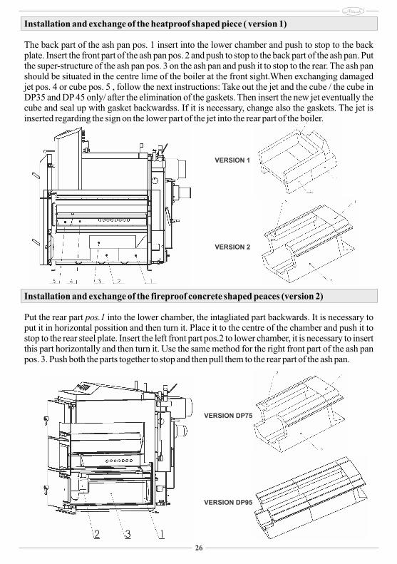
Installation and exchange of the heatproof shaped piece ( version 1)
The back part of the ash pan pos. 1 insert into the lower chamber and push to stop to the back plate. Insert the front part of the ash pan pos. 2 and push to stop to the back part of the ash pan. Put the super-structure of the ash pan pos. 3 on the ash pan and push it to stop to the rear. The ash pan should be situated in the centre lime of the boiler at the front sight.When exchanging damaged jet pos. 4 or cube pos. 5 , follow the next instructions: Take out the jet and the cube / the cube in DP35 and DP 45 only/ after the elimination of the gaskets. Then insert the new jet eventually the cube and seal up with gasket backwardss. If it is necessary, change also the gaskets. The jet is inserted regarding the sign on the lower part of the jet into the rear part of the boiler.
Installation and exchange of the fireproof concrete shaped peaces (version 2)
Put the rear part pos.1 into the lower chamber, the intagliated part backwards. It is necessary to put it in horizontal possition and then turn it. Place it to the centre of the chamber and push it to stop to the rear steel plate. Insert the left front part pos.2 to lower chamber, it is necessary to insert this part horizontally and then turn it. Use the same method for the right front part of the ash pan pos. 3. Push both the parts together to stop and then pull them to the rear part of the ash pan.
27
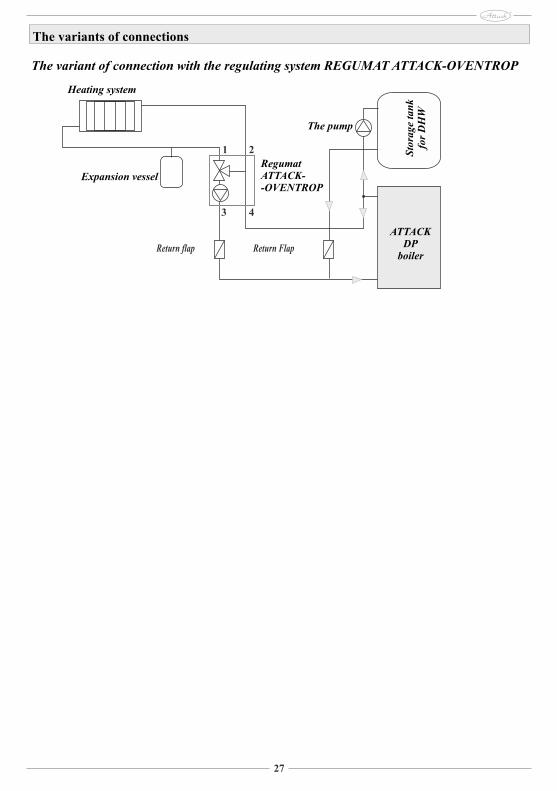
The variants of connections
The variant of connection with the regulating system REGUMAT ATTACK-OVENTROP
ATTACKDP
boiler
Expansion vessel
The pump
RegumatATTACK--OVENTROP
Heating system
Sto
rage
tan
k fo
r D
HW
1 2
43
Return flap Return Flap
28
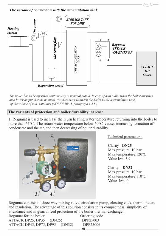
The variant of connection with the accumulation tank
ATTACKDP
boiler
RegumatATTACK--OVENTROP
Heatingsystem
TH
E A
CC
UM
UL
AT
ION
T
AN
K
STORAGE TANK FOR DHW
Th
e pu
mp
Expansion vessel
the
retu
rn f
lap
The boiler has to be operated continuously in nominal output. In case of heat outlet when the boiler operates on a lower output that the nominal, it is necessary to attach the boiler to the accumulation tank of the volume of min. 460 litres (STN EN 303-5, paragraph 4.2.5 ).
1. Regumat is used to increase the reurn heating water temperature returning into the boiler to more than 65°C. The return water temperature below 60°C causes increasing formation of condensate and the tar, and then decreasing of boiler durability.
Technical parameters:
Clarity DN25 Max.pressure 10 bar Max.temperature 120°C Value kvs 3,9
Clarity DN32 Max.pressure 10 bar Max.temperature 110°C Value kvs 0
Regumat consists of three-way mixing valve, circulation pump, closting cock, thermometers and insulation. The advantage of this solution consists in its compactness, simplicity of attendance and in guarranteed protection of the boiler thermal exchanger.Regumat for the boiler Ordering codeATTACK DP25, DP35 (DN25) DPP25003ATTACK DP45, DP75, DP95 (DN32) DPP25006
The variants of protection and boiler durability increase
1 2
43
1 2
43
29
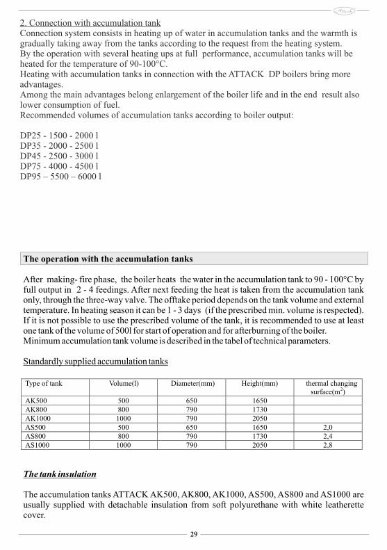
2. Connection with accumulation tankConnection system consists in heating up of water in accumulation tanks and the warmth is gradually taking away from the tanks according to the request from the heating system. By the operation with several heating ups at full performance, accumulation tanks will be heated for the temperature of 90-100°C. Heating with accumulation tanks in connection with the ATTACK DP boilers bring more advantages.Among the main advantages belong enlargement of the boiler life and in the end result also lower consumption of fuel.Recommended volumes of accumulation tanks according to boiler output:
DP25 - 1500 - 2000 lDP35 - 2000 - 2500 lDP45 - 2500 - 3000 lDP75 - 4000 - 4500 lDP95 – 5500 – 6000 l
The operation with the accumulation tanks
After making- fire phase, the boiler heats the water in the accumulation tank to 90 - 100°C by full output in 2 - 4 feedings. After next feeding the heat is taken from the accumulation tank only, through the three-way valve. The offtake period depends on the tank volume and external temperature. In heating season it can be 1 - 3 days (if the prescribed min. volume is respected). If it is not possible to use the prescribed volume of the tank, it is recommended to use at least one tank of the volume of 500l for start of operation and for afterburning of the boiler. Minimum accumulation tank volume is described in the tabel of technical parameters.
Standardly supplied accumulation tanks
The tank insulation
The accumulation tanks ATTACK AK500, AK800, AK1000, AS500, AS800 and AS1000 are usually supplied with detachable insulation from soft polyurethane with white leatherette cover.
Type of tank Volume(l) Diameter(mm) Height(mm) thermal changing surface(m2)
AK500 500 650 1650 AK800 800 790 1730 AK1000 1000 790 2050 AS500 500 650 1650 2,0 AS800 800 790 1730 2,4 AS1000 1000 790 2050 2,8
30
The advantages
The boiler installation together with the accumulation tank offers several advantages:
- lower fuel consumption (up to 30%). The boiler works in full output to fuel burn-up when the optimal operation is observed - High chimney and boiler durability and minimum formation of acids and condensate - Possibility of combination with another heating sources ( solar panels...)- conjunction of boiler and floorheating- confortable and ecological heating
Unsecured cooling circulation in the cooling circuit when the STS20 valve is opened, can cause the boiler damage! In that case the guarrantee cannot be applied. Instructions for liquidation of the product after its lifetimeAfter the period of use the product has to be liquidated in a compliance with the local standards and norms. Liquidation of wrappingThe wrapping has to be liquidated according to local standards and norms.
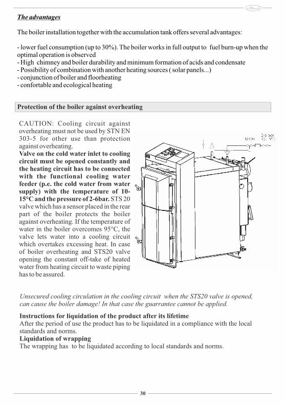
Protection of the boiler against overheating
CAUTION: Cooling circuit against overheating must not be used by STN EN 303-5 for other use than protection against overheating.Valve on the cold water inlet to cooling circuit must be opened constantly and the heating circuit has to be connected with the functional cooling water feeder (p.e. the cold water from water supply) with the temperature of 10-15°C and the pressure of 2-6bar. STS 20 valve which has a sensor placed in the rear part of the boiler protects the boiler against overheating. If the temperature of water in the boiler overcomes 95°C, the valve lets water into a cooling circuit which overtakes excessing heat. In case of boiler overheating and STS20 valve opening the constant off-take of heated water from heating circuit to waste piping has to be assured.
32
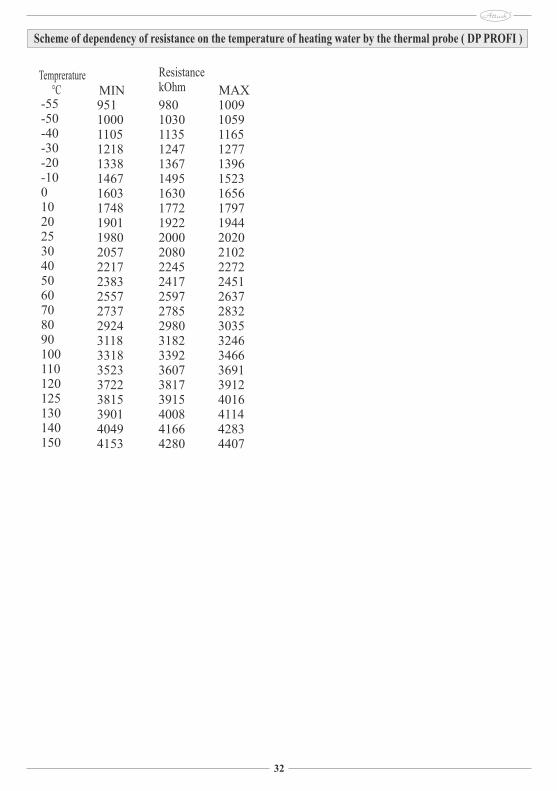
Scheme of dependency of resistance on the temperature of heating water by the thermal probe ( DP PROFI )
Temprerature °C-55-50-40-30-20-10010202530405060708090100110120125130140150
95110001105121813381467160317481901198020572217238325572737292431183318352337223815390140494153
ResistancekOhm
98010301135124713671495163017721922200020802245241725972785298031823392360738173915400841664280
100910591165127713961523165617971944202021022272245126372832303532463466369139124016411442834407
MIN MAX