Embed Size (px)
Citation preview
8/3/2019 Attenuation(Complete Losses)
http://slidepdf.com/reader/full/attenuationcomplete-losses 1/10
The attenuation of an optical fiber measures the amount of light lost between input and output. Total
attenuation is the sum of all losses.
Optical losses of a fiber are usually expressed in decibels per kilometer (dB/km). The expression is called
the fiber’s attenuation coefficient α and the expression is
where P(z) is the optical power at a position z from the origin, P(0) is the power at the origin.
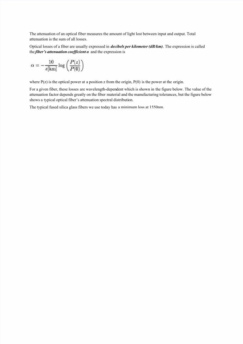
For a given fiber, these losses are wavelength-dependent which is shown in the figure below. The value of the
attenuation factor depends greatly on the fiber material and the manufacturing tolerances, but the figure below
shows a typical optical fiber’s attenuation spectral distribution.
The typical fused silica glass fibers we use today has a minimum loss at 1550nm.
8/3/2019 Attenuation(Complete Losses)
http://slidepdf.com/reader/full/attenuationcomplete-losses 2/10
Optical Fiber Loss Mechanisms
Absorption
Absorption is uniform. The same amount of the same material always absorbs the same fraction of light at the
same wavelength. If you have three blocks of the same type of glass, each 1-centimeter thick, all three will
absorb the same fraction of the light passing through them.
Absorption also is cumulative, so it depends on the total amount of material the light passes through. If the
absorption is 1% per centimeter, it absorbs 1% of the light in the first centimeter, and 1% of
the remaining light the next centimeter, and so on.
8/3/2019 Attenuation(Complete Losses)
http://slidepdf.com/reader/full/attenuationcomplete-losses 3/10
Intrinsic Material Absorption
Intrinsic absorption is caused by interaction of the propagating lightwave with one more more major
components of glass that constitute the fiber’s material composition. These looses represent a fundamental
minimum to the attainable loss and can be overcome only by changing the fiber material.
An example of such an interaction is the infrared absorption band of SiO2 shown in the above figure.
However, in the wavelength regions of interest to optical communication (0.8-0.9um and 1.2-1.5um), infrared
absorption tails make negligible contributions.
Extrinsic Impurity Ions Absorption
Extrinsic impurity ions absorption is caused by the presence of minute quantity of metallic ions (such as Fe2+,
Cu2+, Cr 3+) and the OH- ion from water dissolved in glass. The attenuation from these impurity ions is shown in
the following table.
Impurity Ion Loss due to 1ppm of impurity(dB/km)
Absorption Peak Wavelength(um)
Fe2+ 0.68 1.1
Fe2+
0.15 0.4Cu2+ 1.1 0.85
Cr 3+ 1.6 0.625
V4+ 2.7 0.725
OH- 1.0 0.95
OH- 2.0 1.24
OH- 4.0 1.38
From the table above, we can see that 1 part per million (ppm) of Fe2+ would lead to a loss of 0.68 dB/km at
1.1um. This shows the necessity of ultrapure fibers. Luckily, losses due to the metallic ions can be reduced tovery low by refining the glass mixture to an impurity level below 1 par per billion (ppb).
The OH- ion from water vapor in the glass leads to absorption peaks at 0.72um, 0.88um, 0.95um, 1.13um,
1.24um and 1.38um. The broad peaks at 1.24um and 1.38um in the first figure cure are due to OH- ion. The
good news is OH- ion absorption band is narrow enough that ultrapure fibers can achieve losses less than 0.2
dB/km at 1.55um.
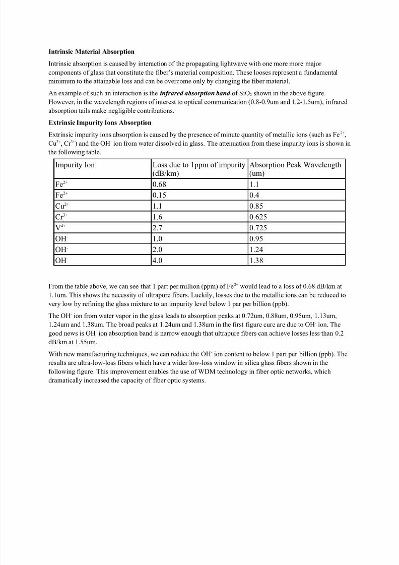
With new manufacturing techniques, we can reduce the OH- ion content to below 1 part per billion (ppb). The
results are ultra-low-loss fibers which have a wider low-loss window in silica glass fibers shown in the
following figure. This improvement enables the use of WDM technology in fiber optic networks, which
dramatically increased the capacity of fiber optic systems.
8/3/2019 Attenuation(Complete Losses)
http://slidepdf.com/reader/full/attenuationcomplete-losses 4/10
Hydrogen Effects
When fused silica glass fiber is exposed to hydrogen gas, attenuation of the fiber also increases. The hydrogen
can interact with the glass to produce hydroxyl ions and their losses. Hydrogen can also infiltrate the fiber and
produce its own losses near 1.2um and 1.6um.
The fibers can come into contact with hydrogen which is produced by corrosion of steel-cable strength
members or by certain bacteria. The way to solve this problem is to add a coating to the fiber that is
impermeable to hydrogen.
Scattering
Scattering losses occur when a wave interacts with a particle in a way that removes energy in the directional
propagating wave and transfers it to other directions. The light isn’t absorbed, just sent in another direction.
However, the distinction between scattering and absorption doesn’t matter much because the light is lost from
the fiber in either case.
There are two main types of scattering: linear scattering and nonlinear scattering.
For linear scattering, the amount of light power that is transferred from a wave is proportional to the power in
the wave. It is characterized by having no change in frequency in the scattered wave.
On the other hand, nonlinear scattering is accompanied by a frequency shift of the scattered light. Nonlinear
scattering is caused by high values of electric field within the fiber (modest to high amount of optical power). Nonlinear scattering causes significant power to be scattered in the forward, backward, or sideways directions.
Rayleigh Scattering (Linear Scattering)
Rayleigh scattering (named after the British physicist Lord Rayleigh) is the main type of linear scattering. It is
caused by small-scale (small compared with the wavelength of the lightwave) inhomogeneities that are
produced in the fiber fabrication process. Examples of inhomogeneities are glass composition fluctuations
(which results in minute refractive index change) and density fluctuations (fundamental and not improvable).
Rayleigh scattering accounts for about 96% of attenuation in optical fiber.
8/3/2019 Attenuation(Complete Losses)
http://slidepdf.com/reader/full/attenuationcomplete-losses 5/10
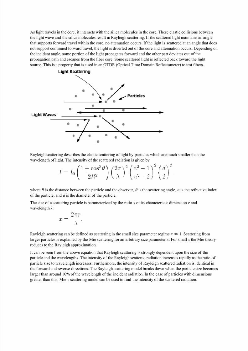
As light travels in the core, it interacts with the silica molecules in the core. These elastic collisions between
the light wave and the silica molecules result in Rayleigh scattering. If the scattered light maintains an angle
that supports forward travel within the core, no attenuation occurs. If the light is scattered at an angle that does
not support continued forward travel, the light is diverted out of the core and attenuation occurs. Depending on
the incident angle, some portion of the light propagates forward and the other part deviates out of the
propagation path and escapes from the fiber core. Some scattered light is reflected back toward the lightsource. This is a property that is used in an OTDR (Optical Time Domain Reflectometer) to test fibers.
Rayleigh scattering describes the elastic scattering of light by particles which are much smaller than the
wavelength of light. The intensity of the scattered radiation is given by
where R is the distance between the particle and the observer, θ is the scattering angle, n is the refractive index
of the particle, and d is the diameter of the particle.
The size of a scattering particle is parameterized by the ratio x of its characteristic dimension r and
wavelength λ:
Rayleigh scattering can be defined as scattering in the small size parameter regime x ≪ 1. Scattering from
larger particles is explained by the Mie scattering for an arbitrary size parameter x. For small x the Mie theory
reduces to the Rayleigh approximation.It can be seen from the above equation that Rayleigh scattering is strongly dependent upon the size of the
particle and the wavelengths. The intensity of the Rayleigh scattered radiation increases rapidly as the ratio of
particle size to wavelength increases. Furthermore, the intensity of Rayleigh scattered radiation is identical in
the forward and reverse directions. The Rayleigh scattering model breaks down when the particle size becomes
larger than around 10% of the wavelength of the incident radiation. In the case of particles with dimensions
greater than this, Mie’s scattering model can be used to find the intensity of the scattered radiation.
8/3/2019 Attenuation(Complete Losses)
http://slidepdf.com/reader/full/attenuationcomplete-losses 6/10
Rayleigh scattering depends not on the specific type of material but on the size of the particles relative to the
wavelength of light. The loss due to Rayleigh scattering is proportional to λ -4 and obviously decreases rapidly
with increase in wavelength (see the first figure above – Loss vs.. Wavelength). Short wavelengths are
scattered more than longer wavelengths. Any wavelength that is below 800nm is unusable for optical
communication because attenuation due to Rayleigh scattering is too high.
The attenuation coefficient due to Rayleigh scattering in (pure) fused silica is given by the following
approximate formula
where
α0 = 1.7 dB/km at λ 0 = 0.85um
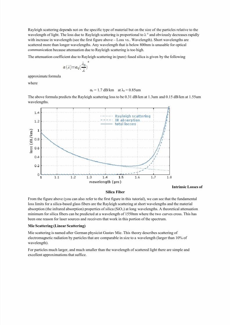
The above formula predicts the Rayleigh scattering loss to be 0.31 dB/km at 1.3um and 0.15 dB/km at 1.55um
wavelengths.
Intrinsic Losses of
Silica Fiber
From the figure above (you can also refer to the first figure in this tutorial), we can see that the fundamental
loss limits for a silica-based glass fibers are the Rayleigh scattering at short wavelengths and the material
absorption (the infrared absorption) properties of silica (SiO2) at long wavelengths. A theoretical attenuation
minimum for silica fibers can be predicted at a wavelength of 1550nm where the two curves cross. This has
been one reason for laser sources and receivers that work in this portion of the spectrum.
Mie Scattering (Linear Scattering)Mie scattering is named after German physicist Gustav Mie. This theory describes scattering of
electromagnetic radiation by particles that are comparable in size to a wavelength (larger than 10% of
wavelength).
For particles much larger, and much smaller than the wavelength of scattered light there are simple and
excellent approximations that suffice.
8/3/2019 Attenuation(Complete Losses)
http://slidepdf.com/reader/full/attenuationcomplete-losses 7/10
For glass fibers, Mie scattering occurs in inhomogeneities such as core-cladding refractive index variations
over the length of the fiber, impurities at the core-cladding interface, strains or bubbles in the fiber, or diameter
fluctuations.
Mie scattering can be reduced by carefully removing imperfections from the glass material, carefully
controlling the quality and cleanliness of the manufacturing process.
In commercial fibers, the effects of Mie scattering are insignificant. Optical fibers are manufactured with very
few large defects. (larger than 10% of wavelength)
Here is an interactive Mie Scattering calculator on the web developed by Scott Prahl.
Brillouin Scattering (Nonlinear Scattering)
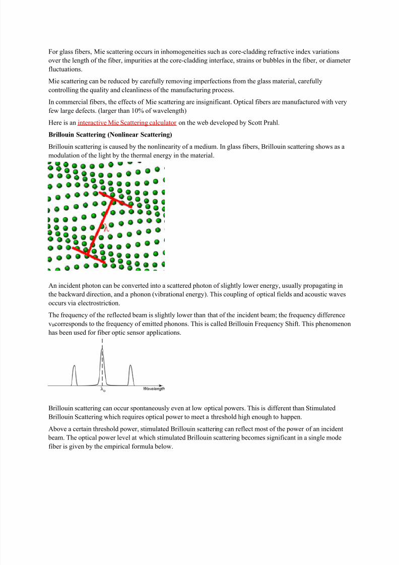
Brillouin scattering is caused by the nonlinearity of a medium. In glass fibers, Brillouin scattering shows as a
modulation of the light by the thermal energy in the material.
An incident photon can be converted into a scattered photon of slightly lower energy, usually propagating in
the backward direction, and a phonon (vibrational energy). This coupling of optical fields and acoustic wavesoccurs via electrostriction.
The frequency of the reflected beam is slightly lower than that of the incident beam; the frequency difference
vBcorresponds to the frequency of emitted phonons. This is called Brillouin Frequency Shift. This phenomenon
has been used for fiber optic sensor applications.
Brillouin scattering can occur spontaneously even at low optical powers. This is different than Stimulated
Brillouin Scattering which requires optical power to meet a threshold high enough to happen.
Above a certain threshold power, stimulated Brillouin scattering can reflect most of the power of an incident
beam. The optical power level at which stimulated Brillouin scattering becomes significant in a single mode
fiber is given by the empirical formula below.
8/3/2019 Attenuation(Complete Losses)
http://slidepdf.com/reader/full/attenuationcomplete-losses 8/10
where
PB = Stimulated Brillouin Scattering Optical Power Level Threshold (watts)
a’ = Fiber radius (um)
λ’ = Light source wavelength (um)
α = Fiber loss (dB/km)
△v’ = Light source linewidth (GHz)
Stimulated Raman Scattering (Nonlinear Scattering)
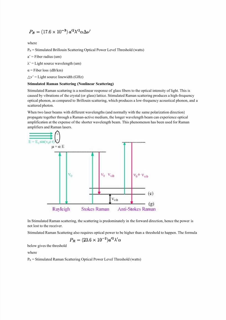
Stimulated Raman scattering is a nonlinear response of glass fibers to the optical intensity of light. This is
caused by vibrations of the crystal (or glass) lattice. Stimulated Raman scattering produces a high-frequency
optical phonon, as compared to Brillouin scattering, which produces a low-frequency acoustical phonon, and a
scattered photon.
When two laser beams with different wavelengths (and normally with the same polarization direction) propagate together through a Raman-active medium, the longer wavelength beam can experience optical
amplification at the expense of the shorter wavelength beam. This phenomenon has been used for Raman
amplifiers and Raman lasers.
In Stimulated Raman scattering, the scattering is predominately in the forward direction, hence the power is
not lost to the receiver.
Stimulated Raman Scattering also requires optical power to be higher than a threshold to happen. The formula
below gives the threshold
where
PR = Stimulated Raman Scattering Optical Power Level Threshold (watts)
8/3/2019 Attenuation(Complete Losses)
http://slidepdf.com/reader/full/attenuationcomplete-losses 9/10
a’ = Fiber radius (um)
λ’ = Light source wavelength (um)
α = Fiber loss (dB/km)
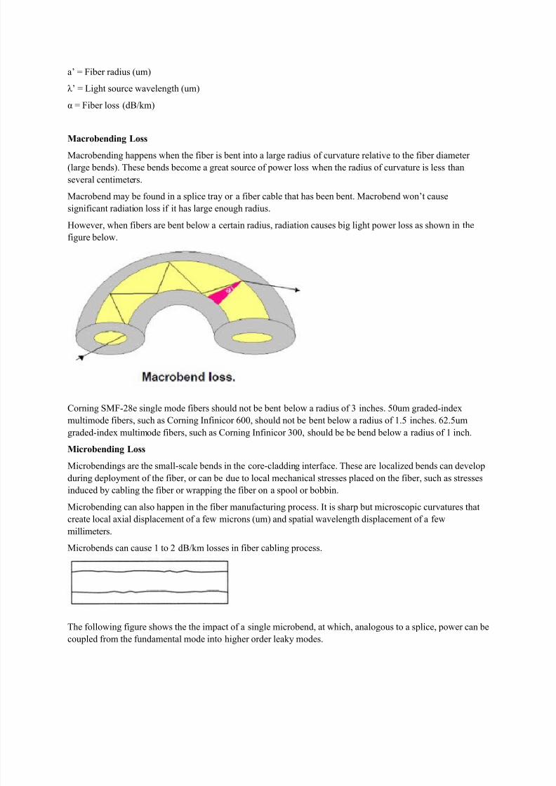
Macrobending Loss
Macrobending happens when the fiber is bent into a large radius of curvature relative to the fiber diameter
(large bends). These bends become a great source of power loss when the radius of curvature is less than
several centimeters.
Macrobend may be found in a splice tray or a fiber cable that has been bent. Macrobend won’t cause
significant radiation loss if it has large enough radius.
However, when fibers are bent below a certain radius, radiation causes big light power loss as shown in the
figure below.
Corning SMF-28e single mode fibers should not be bent below a radius of 3 inches. 50um graded-indexmultimode fibers, such as Corning Infinicor 600, should not be bent below a radius of 1.5 inches. 62.5um
graded-index multimode fibers, such as Corning Infinicor 300, should be be bend below a radius of 1 inch.
Microbending Loss
Microbendings are the small-scale bends in the core-cladding interface. These are localized bends can develop
during deployment of the fiber, or can be due to local mechanical stresses placed on the fiber, such as stresses
induced by cabling the fiber or wrapping the fiber on a spool or bobbin.
Microbending can also happen in the fiber manufacturing process. It is sharp but microscopic curvatures that
create local axial displacement of a few microns (um) and spatial wavelength displacement of a few
millimeters.
Microbends can cause 1 to 2 dB/km losses in fiber cabling process.
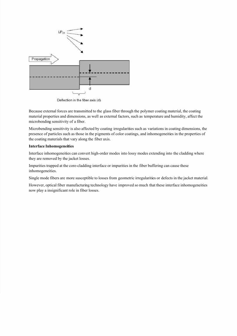
The following figure shows the the impact of a single microbend, at which, analogous to a splice, power can be
coupled from the fundamental mode into higher order leaky modes.
8/3/2019 Attenuation(Complete Losses)
http://slidepdf.com/reader/full/attenuationcomplete-losses 10/10
Because external forces are transmitted to the glass fiber through the polymer coating material, the coating
material properties and dimensions, as well as external factors, such as temperature and humidity, affect themicrobending sensitivity of a fiber.
Microbending sensitivity is also affected by coating irregularities such as variations in coating dimensions, the
presence of particles such as those in the pigments of color coatings, and inhomogeneities in the properties of
the coating materials that vary along the fiber axis.
Interface Inhomogeneities
Interface inhomogeneities can convert high-order modes into lossy modes extending into the cladding where
they are removed by the jacket losses.
Impurities trapped at the core-cladding interface or impurities in the fiber buffering can cause these
inhomogeneities.
Single mode fibers are more susceptible to losses from geometric irregularities or defects in the jacket material.
However, optical fiber manufacturing technology have improved so much that these interface inhomogeneities
now play a insignificant role in fiber losses.