Embed Size (px)
Citation preview
Naval Research LaboratoryWashington, DC 20375-5000
AD-A248 393 NRL/MR/6505-92693
Procedure for Measuring Radiation-Induced Attenuation Xin Optical Fibers and Optical Cables
NATO Nuclear Effects Task GroupA/C 243, Panel IV (RSG.12)
E. J. FRIEBELE, Chairman
Optical Materials Research GroupOptical Sciences Division
March 27, 1992 A- T9IPRi O91j
92-09140hil III h~lll, hh U U
Approved for public release; distribution is unlimited.
92 t 88 83
REPORT DOCUMENTATION PAGE [MB No. 0704-0188
PU~iC reporting bu¢dnl fat this COfct~lol Of informati0n it estimated to average 1 hour per respOnse. inCluding the time for r viewsl iflstrUCtios. searching eisting data sources.galthering anfd maintalllnig t he dalta nee11.ded, aind compl~letinlg andc reiivewingK the oleton Of iftlt~oirm itd (l~ omment retardin fS~jthi bDurden estimite or alny Other asoeci 0$ h I~
collection or ifoWti iOn. includini suggestions for reducing tan burd-n, to Washi nton Headquarters Services. Directorate for information Operations aid Reports. a15 IS JeffersonDarnS Highway. Suite 1204. Arlington. VA 22202.4302, a:d to the Office of Mnagement and Budget. Paperwork Reduntion Prolect (0704-18). Wlashington, DC 20S03.
1. AGENCY USE ONLY (Leave blank) 2. REPORT DATE 3. REPORT TYPE AND DATES COVERED
March 27. 19924. TITLE AND SUBTITLE S. FUNDING NUMBERS
Procedure for Measuring Radiation-Induced Attenuation in Optical Fibersand Optical Cables
6. AUTHOR(S)
E. J. Friebele,* Chairman
7. PERFORMING ORGANIZATION NAME(S) AND ADDRESS(ES) S. PERFORMING ORGANIZATION
REPORT NUMBER
Naval Research LaboratoryWashington, DC 20375-5000 NRL/MR/6505-92-6963
9. SPONSORING/ MONITORING AGENCY NAME(S) AND ADDRESS(ES) 10. SPONSORING/ MONITORINGAGENCY REPORT NUMBER
11. SUPPLEMENTARY NOTES*NATO Panel IV, Research Study Group 12
Nuclear Effects Task Group
12a. DISTRIBUTION / AVAILABILITY STATEMENT 12b. DISTRIBUTION CODE
Approved for public release; distribution is unlimited.
13. ABSTRACT (Maximum 200 words)
This test procedure outlines methods for measuring both the steady state response of optical fibers andcables exposed to continuous radiation and the transient response of optical fibers and cables exposed to a pulseof radiation. It can be used to determine the level of radiation-induced attenuation produced in single-mode ormultimode optical fibers, in either cabled or uncabled form.
14. SUBJECT TERMS 15. NUMBER OF PAGES
Fiber optics 16. PRICE CODENuclear radiation effects
17. SECURITY CLASSIFICATION 18. SECURITY CLASSIFICATION 19. SECURITY CLASSIFICATION 20. LIMITATION OF ABSTRACT
UNCLASSIFIED UNCLASSIFIED I UNCLASSIFIED ULNSN 7540-01-280-5500 Standard Form 298 (Rev 2-89)
Piescr1oed tor ANSI $11 Z39-t8298 102
1.0 INTENT 1
2.0 REFERENCED DOCUMENTS 3
3.0 TEST EQUIPMENT 3
4.0 TEST SAMPLE 9
5.0 TEST PROCEDURE 11
6.0 CALCULATIONS 17
7.0 REPORT 17
8.0 SPECIFYING INFORMATION 18
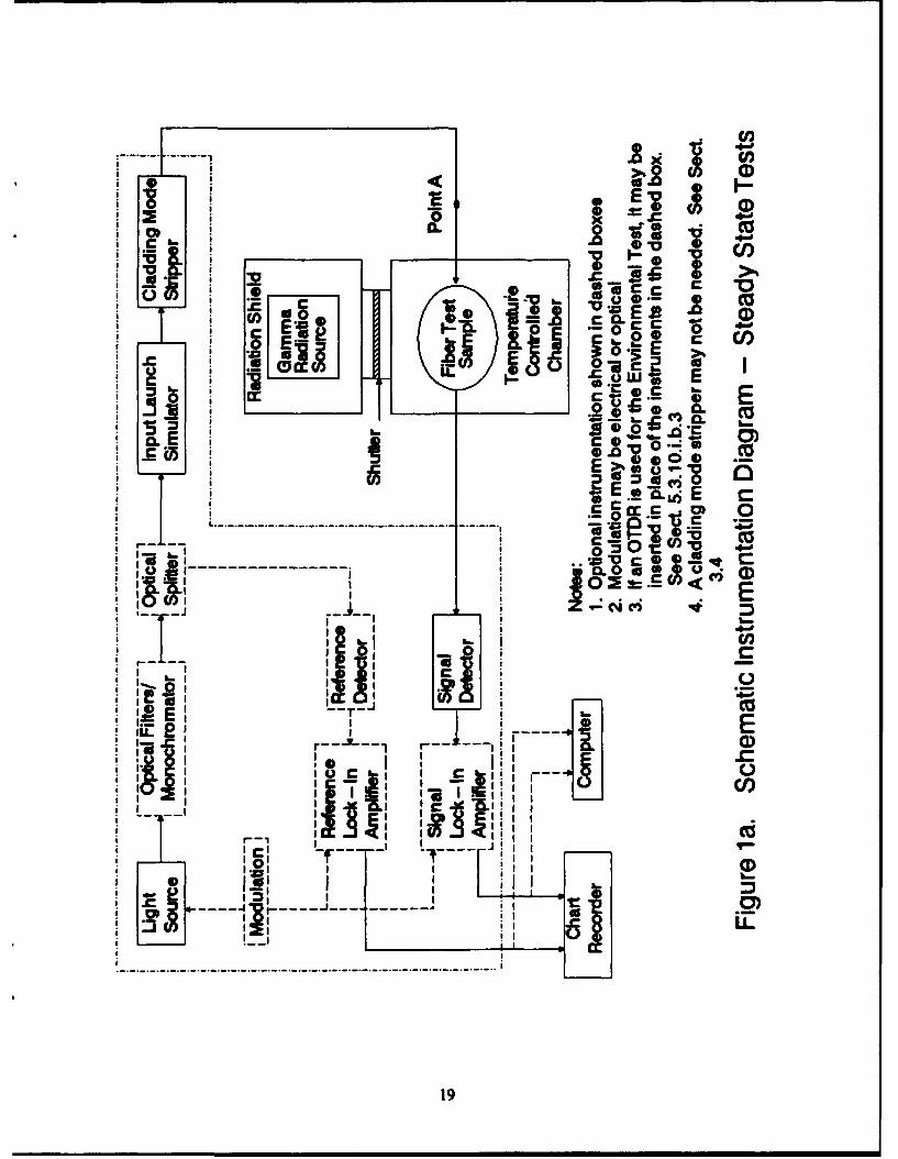
Figure la: Schematic Instrumentation Diagram - Steady State Tests 19
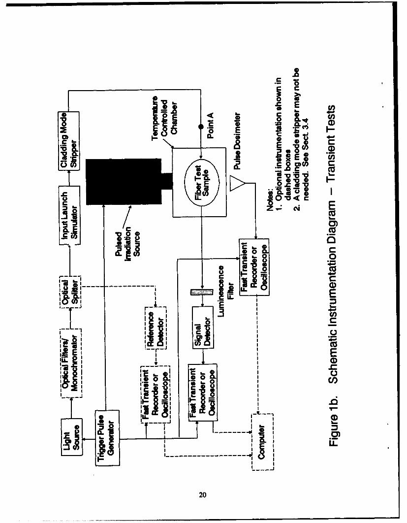
Figure 1b: Schematic Instrumentation Diagram - Transient Tests 20
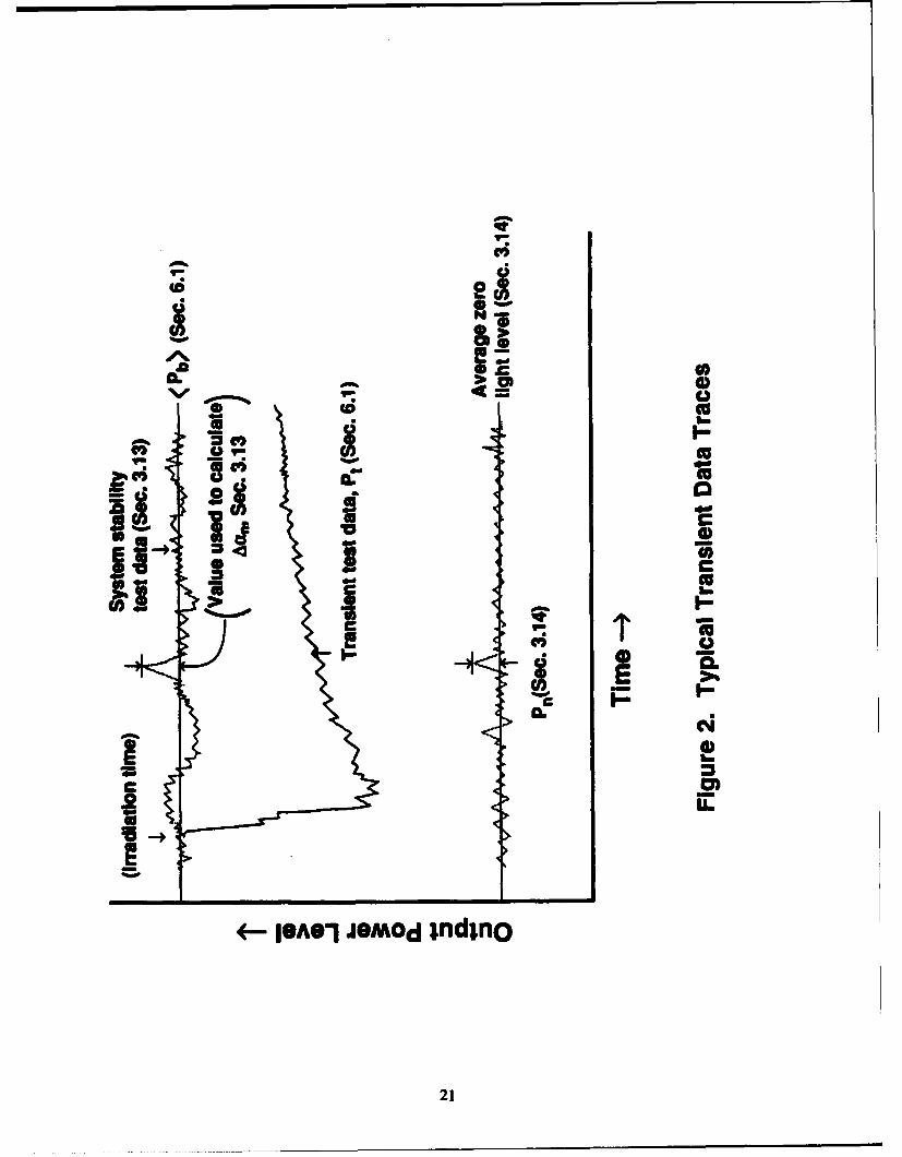
Figure 2: Typical Transient Data Traces 21
Accession For
NTIS GPA&I
; i. r
iii ~
PROCEDURE FOR MEASURING RADIATION-INDUCED ATTENUATION
IN OPTICAL FIBERS AND OPTICAL CABLES
1.0 INTENT
This test procedure outlines methods for measuring both the steady state responseof optical fibers and cables exposed to continuous radiation and the transient response ofoptical fibers and cables exposed to a pulse of radiation. It can be used to determine thelevel of radiation-induced attenuation produced in single-mode or multimode opticalfibers, in either cabled or uncabled form. This test procedure is not intended to test thenon-optical components of a fiber-optic cable. Other test methods may be required toevaluate the degradation of cable materials resulting from radiation exposure. [Theprocedure specifically addresses steady state gamma-ray, and transient gamma-ray, X ray,or electron pulsed exposures, but it would be applicable to other radiation sources (e.g.,protons, neutrons) as well, with appropriate changes in dosimetry and shieldingconsiderations.]
1.1 Background
The attenuation of optical fibers generally increases when exposed to radiation.This is primarily due to the trapping of radiolytic electrons and holes at defect sites inthe glass, i.e., the formation of color centers. The depopulation of color centers bythermal or optical (photobleaching) processes causes recovery, usually resulting in adecrease of radiation-induced attenuation. Recovery occurs simultaneously withdarkening during exposure and is evident immediately after irradiation. Recovery of theattenuation after an irradiation depends on many variables, including the temperature ofthe test sample, the configuration of the sample, the spectrum and type of radiation used,the total dose applied to the test sample, and the light level used to measure attenuation.Under some conditions, recovery is never complete. The attenuation of an optical fibercan vary as a function of time following pulsed exposure by four or more decades duringthe recovery process.
This test procedure addresses both the steady state and pulsed radiationenvironment. Steady state measurements generally use radioactive isotope sources forwhich the turn-on and turn-off times are typically comparable to 1 s. This correspondsto the times required to move the source itself, shields, or test samples in and out of thesource. The instrumentation used for steady state measurements typically has a timeresponse of -0.1 s. There are two extremes of steady state exposure: the low dose rateregime for estimating the effect of environmental background radiation, and the highdose rate regime for estimating the effects of adverse nuclear environments, e.g., nuclearweapons detonation, specific areas of nuclear power plants, and accelerators. The effectsof environmental background radiation are tested by a two-point attenuationmeasurement approach similar to FOTP-46 or FOTP-78. Alternatively, an optical timedomain reflectometer (OTDR) may provide a more convenient measurement capabilityin some circumstances. The effects of adverse nuclear environments are tested bymeasuring the attenuation of the optical power (by monitoring either the transmitted orreflected light; the latter are tested by OTDR) before, during, and after exposure of the
The Nuclear Effects Task Group of NATO A/C 243. Panel IV (RSG. 12) modified the FOTP-49A procedure based on their collectiveexperience in over five years of effort to develop reliable technique to measure radiation-induced attenuation in optical fibers. Thisprocedures has been submitted to EIA as FOTP-64.
Manuscript approved January 29. 1992.
test sample to gamma radiation. The Detail Specification should specify the times atwhich measurements are to be made, based on the intended application.
The response of fibers to the pulsed environment addresses the time-varying(transient) behavior of an optical fiber after exposure to a single pulsed dose ofradiation. This pulsed dose, with durations of < 1 s, is typically generated by varioustypes of accelerators. The transient protocol is applicable where the radiation is not onlydelivered in a short pulse, but where fiber performance is to be determined on a timescale <51 s. For measurements at times after irradiation that are long compared to 1 s ormeasurements of the average response (r > 1 s) of fibers to a series of short pulses, thesteady state protocol is applicable. The transient radiation-induced attenuation is testedby monitoring transmitted light power before, during, and after exposure of the testsample to the radiation pulse.
The transient procedure can be used to document transient attenuation fromgamma rays, X rays, or electrons. (Interaction of gamma and X rays involves processesthat generate electrons or positrons having energies comparable to the gamma rayenergy.) Since few pulsed gamma/X-ray laboratory sources exist that can deliver large(>500 rad) radiation doses over significant volumes, most testing of such phenomena hasinvolved pulsed electron sources. These irradiations yield the same results because theinteraction of gamma rays and X rays with matter produces energetic electrons by theCompton process. Different applications of optical fibers may require drasticallydifferent recovery capabilities after a single pulse of radiation. For some applicationsnear accelerators, for example, data may be transmitted through the fibers in coincidencewith the radiation pulse. For some military applications involving control systems ortelecommunications, system "down times" of milliseconds may be tolerable; otherapplications may be able to accommodate down times of minutes. For these reasons,this procedure does not specify times at which measurements are to be made. Thatinformation must appear in the Detail Specification based on the intended application.
Radiation exposures may result in luminescence phenomena that generate light inthe fiber. Light will be generated during the pulsed radiation with gamma rays, X rays,or electrons through the Cerenkov process. Although the described procedure discussesonly measurements of attenuation, the presence of transient terenkov or otherluminescent light must be anticipated by users. These sources of light couId overloadrecording instrumentation and compromise system accuracy. In this procedure, outputfilters limit the fraction of the out-of-band luminescent or terenkov light reaching thedetector. A short wavelength cutoff filter to eliminate all light just below the testwavelength of interest could be sufficient for terenkov light because the spectralintensity is proportional to 1/1.
The transient procedure primarily focuses on measurements conducted at shorttimes, generally less than a few minutes. For time scales comparable to one minute orlonger, the steady state procedure may be readily applied. Photobleaching (light-induced
2
annealing) has not been observed at times < 10 jus, even at high optical power levels (500;iW). At longer times, as well as in the steady state procedure, light power levels mustbe precisely specified to minimize photobleaching in some types of fibers.
1.2Cauion
Carefully trained and qualified personnel must be used to perform this test sinceradiation (both ionizing and optical) and electrical hazards will be present.
2.0 REFERENCED DOCUMENTS
Test or inspection requirements include the following references:
FOTP-46 (EIA-455-46) "Spectral Attenuation Measurement for Long-Length,Graded-Index Optical Fibers"
FOTP-50 (EIA-455-50) "Light Launch Conditions for Long-LengthGraded-Index Optical Fiber Spectral Attenuation Measurements"
FOTP-57 (EIA-455-57) "Optical Fiber End Preparation and Examination"FOTP-78 (EIA-455-78) "Spectral Attenuation Cutback Measurement for
Single-Mode Optical Fibers"FOTP-80 (EIA-455-80) "Cutoff Wavelength of Uncabled Single-Mode Fiber by
Transmitted Power"
3.0 TEST EQUIPMENT
Figures la and lb show schematic diagrams of test equipment.
3.1 Radiation Source
The source should provide a variation in dose across the fiber sample notexceeding ± 10%. Average total dose should be expressed in gray [1 Gy = 100 rad] to aprecision of ±5% (steady state) or ± 10% (transient), traceable to national standards.For typical doped silica core fibers, dose should be expressed in Gy calculated for Si0 2,i.e., Gy(Si0 2); if a non-silica-based light guiding material is used, dose should then beexpressed in Gy calculated for that material composition.
3.1.1 Steady State Measurements
Caution: The energy of the gamma rays emitted by the source should be above500 keV to avoid serious complications with rapid variations in total dose as afunction of depth within the fiber and/or cable sample.
Dose rate must be constant for at least 95% of the shortest irradiationtime of interest.
3
3.1.1.i Testing of Environmental BackgEround Radiation
A Co60 or other gamma ray source shall be used to deliverradiation at a dose rate of 0.20 Gy/hour (or as specified in theDetail Specification).
3.1.1.ii Testing of Adverse Steady State Nuclear Environments
A Co60 or other gamma ray source shall be used to deliverradiation at dose rates ranging from 3 to 100 Gy/minute (or asspecified in the Detail Specification).
3.1.2 Transient Measurements
Many types of pulsed electron accelerators are available and may be usedfor testing. Either the electron beam may be used to directly irradiate samples, orthe electron beam may be converted (via the bremsstrahlung process) to deliver anX-ray radiation pulse to the samples.
Note: Theoretical analyses and some data suggest that use of electron/gamma raysources with energies above about 10 MeV may not duplicate irradiations withlower energy sources. The relative importance of ionizing events vs displacementevents in the fiber material will be decreased with the higher energy sources,potentially leading to different recovery processes. Note that if application of afiber requires exposure to radiations that can produce significant atomicdisplacements in the fiber material [neutrons, energetic electrons (above a fewMeV), or protons, for example], then care must be taken to use a radiation sourcethat will duplicate the relative fractions of displacement vs ionization interactions.This is also true if the intended application involves a pulsed environment with acomplex pulse structure; in such cases the test conditions should duplicate thispulse structure as closely as possible. Specific applications would, therefore,benefit from specification of the desired source characteristics to be used forattenuation testing.
If tj represents the earliest time specified in the Detail Specification formeasuring transient attenuation, the radiation source pulse width (full width athalf-maximum, FWHM) should be less than 0.1t, unless otherwise specified, toavoid competition between recovery and damage mechanisms.
The source should be capable of delivering absorbed radiation doses tothe optical fibers of 5 or 100 Gy (or as required in the Detail Specification). Inthe case of low-energy photon or electron irradiations, corrections to the absorbeddose may be required to compensate for fiber buffer or cable materials thatattenuate the beam before interacting with the optical fiber. If a low-energy X-ray
4
source (< 100 keV) is used, the variation of dose through the fiber dimensions maybe so extreme that detailed transport calculations must be used to relate measureddose to the dose actually deposited in the fiber core. X-ray sources should befiltered to > 100 keV unless confidence in dose profiles in the different materialscomprising the fiber, buffer coating, jacket, and cable has been demonstrated.
3.2 Light Source
A light source such as a tungsten-halogen lamp, set of lasers, or LEDs shall beused to produce light at wavelengths of 850 ± 25, 1310 ± 20, and 1550 ± 20 nm, or atwavelengths specified in the Detail Specification. Only one wavelength should be usedduring any single test, unless specified in the Detail Specification.
3.2.1 Steady State Measurements
The optical power coupled from the source into the test sample shallaverage -30 dBm (1 MW), or as listed in the Detail Specification, determined by anoptical power meter or calibrated detector/preamplifier/recorder system accurateto within ± 8%. The light source may be modulated at a 50% duty cycle to enablephase-locked detection techniques.
3.2.2 Transient Measurements
For measurements specified for times less than 10 gs, the optical power isnot limited, and increased power may be required to achieve adequatedetection/recording signal and to avoid complications arising from the level ofCerenkov light generated by the radiation pulse. For longer times, the opticalpower coupled from the source into the test sample shall average -30 dBm (1 MW),measured as in Section 3.2.1, or as listed in the Detail Specification. Amodulated light source may be used, subject to the average power limitationsexpressed above.
Depending on the details of the detection and recording system, it may benecessary to pulse the light source (see Section 3.8).
Note: Even at 1 tW power level, photobleaching may occur at times beyond 10 Ms,
depending on the fiber type and test temperature.
Note: Use of long fiber lengths can lead to a significant variation in the light poweravailable for photobleaching at different positions in the fiber. Calculating attenuationin dB/kn by multiplying the measured induced loss (dB) by 1000/1L, where L is the testlength in m, is allowed only when fibers show no significant photobleaching.
5
3.3 O ptical Filters/Monochromators
A filter or monochromator at the input end of the fiber may be required torestrict wavelengths to the limits of Section 3.2. During a transient test, a filter and/ormonochromator or short wavelength cutoff filters (see Section 1.1) should be used at theoutput end of the fiber to avoid saturation or nonlinearities of the detector and recordinginstrumentation by transient light sources (Cerenkov or other luminescence phenomena).
3.4 Cladding Mode Stripper
A device that extracts cladding modes shall be used at the input end of the testsample unless it has been demonstrated that the fiber coating materials completely stripthe cladding modes.
3.5 Optical Interconnections
The input and output ends of the test sample shall have a stabilized opticalinterconnection, such as a clamp, connector, splice, or weld. During an attenuationmeasurement, the interconnection shall not be changed or adjusted except as necessaryto perform a two-point cutback measurement. (See Section 5.3.4.)
3.6 Optical Splitter
An optical splitter or fiber-optic coupler may divert some portion of the input lightto a reference detector (Figure 1). The reference path may then be used to monitorsystem fluctuations for the duration of a measurement. (If the reference detector isused, all requirements for the detector/recorder bandwidth discussed in Section 3.8,apply to it as well.) Note that if a polarized light source, like a laser, is used, apolarization-insensitive coupler should be used.
3.7 Input Launch Conditions
371 Class Ia Fibers - (Graded Index Multimode Fiber). A means to establishan equilibrium mode distribution must be developed to establish a steady-statemode condition in the irradiated region of the fiber. Refer to FOTP-50.
372 Class IV Fibers - (Single-Mode Fiber). An optical lens system or fiberpigtail may be used to excite the test fiber. If an optical lens system is used, amethod of making the positioning of the fiber less sensitive is to overfill the fibercore spatially and angularly. A mode filter shall be used to remove high-ordermodes whose cutoff is in the wavelength range less than or equal to thefundamental mode cutoff wavelength of the test fiber. The test condition specifiedin Section 4.1 of FOTP-80 satisfies this requirement. When testingpolarization-maintaining fiber, particular care must be given to understanding and
6
documenting the polarization state of light, both injected into the test fiber (andany reference detector) and detected after exiting the test fiber.
3.7. Class Ib/Ic Fibers - (Quasi-graded and Step Index Fibers). The minimalrequirement shall be for the input light to fill the numerical aperture of the testfiber. Launch conditions shall be specified in the Detail Specification.
3.8 Optical Detection
An optical detector that is linear and stable over the range of intensities that areencountered shall be used. A typical system might include a PIN photodiode amplifiedby a current input preamplifier. Although the stability of avalanche photodiodes is notsufficient for steady state measurements, they may be used for transient measurements,provided their stability meets the requirements of Sections 3.13 and 3.14. For steadystate measurements, synchronous detection by a lock-in amplifier can be used.
For transient measurements, the time response of the overall detection system,including the data recording system, must be carefully evaluated. Limited high frequencyor low frequency response of the system may distort measurements unless the followingconditions are documented.
3.8.1 High-Frequency Response
The impulse response width (in seconds) of the total detection andrecording system shall be 10x less than the earliest time at which measurementsare to be recorded or as specified in the Detail Specification. This impulseresponse is most easily verified by injecting an optical pulse, whose pulse width is10x less than the detection/recording system impulse response, into the detectorand measuring the full width at half maximum (FWHM) as displayed with thedata recorder. Alternatively, a modulated light source can be used in conjunctionwith a network analyzer. The high and low bandwidth limits (3 dB points) aredetermined by changing the modulation frequency from low values (>50 Hz) tothe highest value of interest (e.g. 500 MHz).
Note: If capabilities exist to unfold or deconvolve the system time response fromall observed data (using, for example, Fourier transforms), the 10x requirementspecified above can be relaxed. However, even in that case, detailed knowledge ofthe actual system response will be essential in the unfolding process.
3.8.2 Low Frequency Response
The low-frequency response of the entire detector/recording system shouldextend to zero frequency, with a flat gain curve from dc to the high frequencycutoff, i.e., a completely dc-coupled system should be used. If such a dc-coupled
7
system is used, the light source may be run in a continuous mode, andcomplications involving operation of the source in a pulsed mode, and timing thelight source pulse to the radiation pulse are avoided. The cw mode of light sourceoperation also simplifies all absolute optical power measurements. [However, formeasurements at extremely short times, it may be advantageous to use a pulsedsource to obtain adequate light levels that simplify detection and recordingconsiderations since most light sources can deliver higher outputs in a short pulsethan in a cw mode.]
If the detector/recorder system is not dc-coupled, the light source must beused in a pulsed mode. A single, flat-topped light pulse may be used formeasurements to times < < 1IfL, where fL is the low frequency 3 dB point of therecorder. Such a single pulse must be appropriately timed relative to the radiationpulse. The low frequency limit of the system will introduce distortion in theobserved pulse at times comparable to 1/fL. In an ac-coupled system, repetitivepulses or a modulated signal can also be used (and must be used formeasurements to times 2:l/fL), but the modulation frequency f of the pulse trainmust be > 10 fL, and 1/f, i.e. the time between pulses or cycles, must beconsiderably shorter (by at least 10x) than t1 .
3.9 Elements of the Recorder System
A suitable data recording system must be incorporated. For steady statemeasurements, a chart recorder or computer can be used; for transientmeasurements, the recording system must provide a bandwidth commensurate withthe tests specified in Section 3.8. Examples include: a transient digitizer or storageoscilloscope, an analog oscilloscope with either a film or digital camera, a digitalsampling oscilloscope coupled to a data display unit, coherent demodulation of themodulated light signal by a lock-in amplifier (for times > > 1 us), or incoherentdemodulation with a high frequency amplifier and demodulator.
3.10 Radiation Dosimeter
Dosimetry traceable to National Standards shall be used. Dose should bemeasured in the same geometry as the actual fiber core material to ensure thatdose-build-up effects are comparable in the fiber core and the dosimeter. Thedose must be expressed in Gy calculated for the core material.
3.11 Temperature Controlled Container
Unless otherwise specified, the temperature-controlled container shall have thecapability of maintaining the specified temperature to within ± 2°C or as specified in theDetail Specification. The influence of the temperature-controlled container on the dosewithin the test object must be taken into consideration.
8
3.12 Test Reel
The test reel shall not act as a shield for the radiation used in this test or,alternatively, dose must be measured in a geometry that duplicates the effects of reelattenuation. The diameter of the test reel and the winding tension of the fiber caninfluence the observed radiation performance. If reel diameter and fiber tension are notspecified in the Detail Specification, the fiber should be loosely wound on a reeldiameter exceeding 10 cm. (Some radiation sources will require a much more compactfiber geometry, which should be noted in the report discussed in Section 7.)
3.13 System Stability
Stability of the total system under illumination conditions, including tht. iightsource, light injection conditions, variations in fiber microbend conditions, light couplingto a detector, the detector, and the recording device, must be verified prior to anymeasurement for a time exceeding that required for determination of the output powerprior to irradiation Pb and the output power during the duration of the attenuationmeasurement P (see Section 6). During that time, the maximum fluctuation in observedsystem output shall be converted into an apparent change in optical attenuation due tosystem noise (Aan) in dB/km by using either Equation 6.1.A (if no optical splitter andreference detector is used) or 6.2.A (if an optical splitter and reference detector areused). Any subsequent measurement must be rejected if the observed AA (defined inSection 6) does not exceed 10 x Aan.
3.14 Baseline Stability
Baseline stability shall also be verified for a time comparable to the attenuationmeasurement with the light source turned off. The maximum fluctuation in outputpower P. shall be recorded. Any subsequent measurement must be rejected if thetransmitted power out of the irradiated fiber is not greater than 10 x Pn.
4.0 TEST SAMPLE
Either a fiber or cable specimen may be tested. An unirradiated sample shall beused in each test unless otherwise specified in the Detail Specification.
4.1 Fiber Specimen
The test specimen shall be a representative sample of the fiber specified in theDetail Specification.
9
4.2 Cable Specimen
The test specimen shall be a representative sample of the cable described in theDetail Specification and shall contain at least one of the specified fibers.
4.3 Test Specimens
A length at the ends of the test sample shall reside outside of the irradiationchamber and shall be used to connect the fiber into the optical measurement system. Inaddition, the fiber length must be adjusted to meet the system stability limits of Section3.13 and the baseline stability limits of Section 3.14. (If a system is seriously unstable, nofiber length may meet the requirements of Section 3.13 and 3.14. In such a case, themeasurement cannot proceed until the measurement apparatus is improved.) Theirradiated length of the test sample shall be reported.
4.3.1 Environmental Background Radiation Test
Unless otherwise specified in the Detail Specification, tne irradiated lengthof the test sample shall be 500 ± 10 m. The length outside the test chamber shallbe sufficient for a minimum of two cutback measurements (refer to Section 5.3).
4.3.2 Adverse Nuclear Environments Test
Unless otherwise specified in the Detail Specification, the irradiated lengthof the test sample shall be 100 ± 5 m.
4.3.3 Transient Test
The length of the test sample is dependent on the total dose, the timeregime for which measurements are required in the Detail Specification, and thebeam size/uniformity of the irradiation source. The irradiated fiber length shallbe such that the transit time of light through the irradiated region is at least 10xshorter than t, specified for attenuation measurements. For measurements only attimes beyond 1 ms, 100 m length of fiber is recommended for direct comparison tothe steady state specification. This recommendation cannot be followed if theradiation source is not capable of uniformly exposing an irradiation volume largeenough to hold the fiber coil or if the induced attenuation in that length of fiberresults in power throughputs violating the baseline stability test of Sec. 3.14.
4.4 Test Reel
The test sample shall be spooled onto a reel per Section 3.12. Allowance shall bemade for the unspooling of a measured length of the test sample from each end of thereel for attachment to the optical measurement equipment.
10
4.5 Ambient Light Shielding
The irradiated fiber length shall be shielded from ambient light to preventphotobleaching by any external light sources and to avoid apparent baseline shifts in thezero light level. An absorbing fiber coating or jacket can be used as the light shieldprovided it has been demonstrated to block ambient light and its influence on the dosewithin the fiber core has been taken into consideration.
5.0 TEST PROCEDURE
5.1 Calibration of Radiation Source
Calibration of the radiation source for dose uniformity (at a minimum of fourlocations) and dose level shall be made prior to introduction of fiber test samples.Regardless of dosimeter used, per Section 3.1, the variation in dose across the fiber reelvolume shall not exceed ± 10%.
If thermoluminescent detectors (TLDs) are used for the measurements, four TLDsshall be used to sample dose distribution at each location. The readings from themultiple TLDs at each location shall be averaged to minimize dose uncertainties. Tomaintain the highest possible accuracy in dose measurement, the TLDs shall not be usedmore than once. TLDs should be used only in the dose region where they maintain alinear response.
5.1.1 Steady State Sources
Total dose shall be measured with an irradiation time equal to subsequentfiber measurements. Alternatively, the dose rate may be measured, and the totaldose calculated from the product of the dose rate and irradiation time. Sourcetransit time (from off-to-on and on-to-off positions) shall be less than 5% of theirradiation time.
5.1.2 Transient Sources
Various types of dosimetry may be used for source calibration, such asthermoluminescent dosimeters (TLDs), microcalorimeter, radiachromic film, orFaraday cup (for electron beam measurements). Of these alternatives, the TLD,microcalorimeter, and radiachromic film can potentially provide a responsecalibrated directly in absorbed dose. Depending on the composition of the TLD,microcalorimeter, or radiachromic film and the energy spectrum and type(electron beam or bremsstrahlung) of radiation source used, it may be necessary tocorrect the observations to obtain the dose actually deposited in the optical fibermaterial. Such corrections should include dose build-up and/or attenuationfactors that may occur due to materials (such as fiber cable material, fiber buffer
11
material, reel composition, or self-shielding of a fiber coil) and differing electronstopping powers in the detector and fiber materials. Similar materials (such asthin aluminum foils, for example) may be placed in front of the dosimeter tosimulate these phenomena.
A Faraday cup shall be used only as a transfer standard for electronbeams, not as the primary dose-measuring instrument, and it shall be calibratedagainst one of the absorbed dose instruments (TLD, microcalorimeter, orradiachromic film) prior to its use. The Faraday cup will measure only totalcharge, and this quantity may be complicated by a variety of charge loss or gainmechanisms. It does not measure any quantity directly related to absorbed dose.If radiachromic film is used, multiple pulses may be required to obtain adequatedarkening of the film. In this case, a Faraday cup provides a convenientpulse-to-pulse normalization method.
Total dose shall be measured on each pulse of the radiation source, unlessstated otherwise in the Detail Specification.
5.2 Fiber End Preparation
The test sample shall be prepared such that its endfaces are smooth andperpendicular to the fiber axis, in accordance with FOTP-57.
5.3 Data Acquisition Process
5.1 The reel of fiber or cable shall be placed in the attenuation test setupshown in Figure 1. Sufficient fiber should be available on the input end of thefiber to allow an attenuation measurement using the two-point cutback method tobe performed.
5,32 The light source shall be coupled into the input end of the fiber, asdescribed in Section 3.7. The output end of the fiber shall be positioned such thatall light exiting the fiber impinges on the active surface of the detector.
5.3,2 The test sample shall be stabilized in the temperature chamber at 23 ± 20Cprior to proceeding (or at the test temperature specified in the DetailSpecification).
5.34 For all steady state tests and for those transient tests requiring precisepower injection level (i.e., tests requiring attenuation measurements at timeslonger than 10 js), a two-point attenuation measurement shall be completedwithout disturbing the fiber on the test reel in the temperature chamber. Theprocedure of FOTP-46 shall be used for Class Ia fibers. The procedure ofFOTP-78 shall be used for Class IV fibers. (If the OTDR procedure of 5.3.10.i.b.3
12
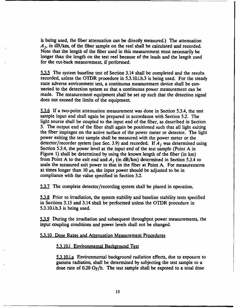
is being used, the fiber attenuation can be directly measured.) The attenuationA1, in dB/km, of the fiber sample on the reel shall be calculated and recorded.Note that the length of the fiber used in this measurement must necessarily belonger than the length on the test reel because of the leads and the length usedfor the cut-back measurement, if performed.
5..5 The system baseline test of Section 3.14 shall be completed and the resultsrecorded, unless the OTDR procedure in 5.3.10.i.b.3 is being used. For the steadystate adverse environment test, a continuous measurement device shall be con-nected to the detection system so that a continuous power measurement can bemade. The measurement equipment shall be set up such that the detection signaldoes not exceed the limits of the equipment.
5.3. If a two-point attenuation measurement was done in Section 5.3.4, the testsample input end shall again be prepared in accordance with Section 5.2. Thelight source shall be coupled to the input end of the fiber, as described in Section3. The output end of the fiber shall again be positioned such that all light exitingthe fiber impinges on the active surface of the power meter or detector. The lightpower exiting the test sample shall be measured with the power meter or thedetector/recorder system (see Sec. 3.9) and recorded. If A I was determined usingSection 5.3.4, the power level at the input end of the test sample (Point A inFigure 1) shall be determined by using the known length of the fiber (in kin)from Point A to the exit end and A1 (in dB/km) determined in Section 5.3.4 toscale the measured exit power to that in the fiber at Point A. For measurementsat times longer than 10 us, the input power should be adjusted to be incompliance with the value specified in Section 3.2.
5.3. The complete detector/recording system shall be placed in operation.
5..U Prior to irradiation, the system stability and baseline stability tests specifiedin Sections 3.13 and 3.14 shall be performed unless the OTDR procedure in5.3.10.i.b.3 is being used.
5..9 During the irradiation and subsequent throughput power measurements, the
input coupling conditions and power levels shall not be changed.
5.3.10 Dose Rates and Attenuation Measurement Procedures
5.3.10.i Environmental Background Test
5.3,101a Environmental background radiation effects, due to exposure togamma radiation, shall be determined by subjecting the test sample to adose rate of 0.20 Gy/h. The test sample shall be exposed to a total dose
13
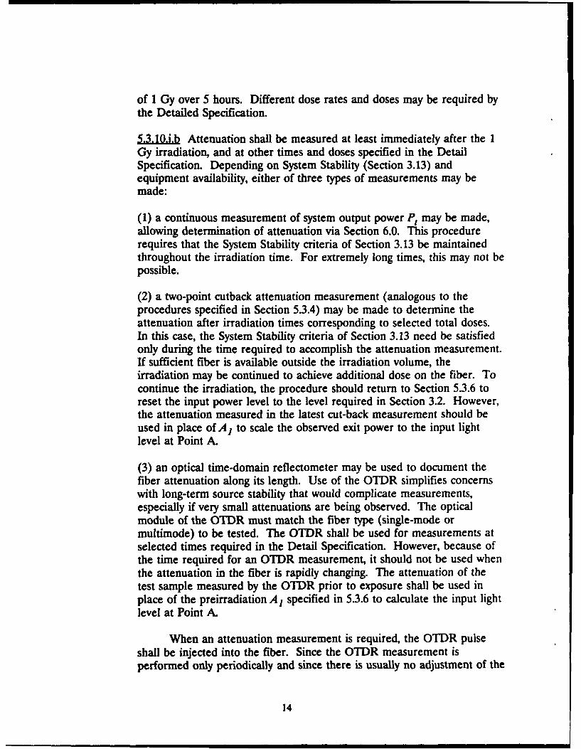
of 1 Gy over 5 hours. Different dose rates and doses may be required bythe Detailed Specification.
5.3.10.1 Attenuation shall be measured at least immediately after the IGy irradiation, and at other times and doses specified in the DetailSpecification. Depending on System Stability (Section 3.13) andequipment availability, either of three types of measurements may bemade:
(1) a continuous measurement of system output power P, may be made,allowing determination of attenuation via Section 6.0. This procedurerequires that the System Stability criteria of Section 3.13 be maintainedthroughout the irradiation time. For extremely long times, this may not bepossible.
(2) a two-point cutback attenuation measurement (analogous to theprocedures specified in Section 5.3.4) may be made to determine theattenuation after irradiation times corresponding to selected total doses.In this case, the System Stability criteria of Section 3.13 need be satisfiedonly during the time required to accomplish the attenuation measurement.If sufficient fiber is available outside the irradiation volume, theirradiation may be continued to achieve additional dose on the fiber. Tocontinue the irradiation, the procedure should return to Section 5.3.6 toreset the input power level to the level required in Section 3.2. However,the attenuation measured in the latest cut-back measurement should beused in place of A1 to scale the observed exit power to the input lightlevel at Point A.
(3) an optical time-domain reflectometer may be used to document thefiber attenuation along its length. Use of the OTDR simplifies concernswith long-term source stability that would complicate measurements,especially if very small attenuations are being observed. The opticalmodule of the OTDR must match the fiber type (single-mode ormultimode) to be tested. The OTDR shall be used for measurements atselected times required in the Detail Specification. However, because ofthe time required for an OTDR measurement, it should not be used whenthe attenuation in the fiber is rapidly changing. The attenuation of thetest sample measured by the OTDR prior to exposure shall be used inplace of the preirradiation A, specified in 5.3.6 to calculate the input lightlevel at Point A.
When an attenuation measurement is required, the OTDR pulseshall be injected into the fiber. Since the OTDR measurement isperformed only periodically and since there is usually no adjustment of the
14
average power injected into the fiber by the OTDR instrument, a meansfor maintaining 1 AW optical power (or as required by the DetailSpecification) continuously injected into the test fiber length as measuredat point A shall be established.
Accurate measurement of fiber loss can be obtained only over thefiber length where the attenuation remains with'n the dynamic range ofthe instrument. In addition, it is extremely important to establish anequilibrium-mode distribution in multimode fibers and to ensure that lightis not propagating in the cladding. See Sections 3.4 and 3.7. The lengthof fiber to be irradiated should be preceded by at least 50 m of lead-infiber, which serves as a self-reference and assists in removal of high-orderlossy modes in multimode fibers. Preferably, this lead-in fiber should bean additional length of the test fiber, but a similar fiber fusion-spliced tothe test fiber may be used.
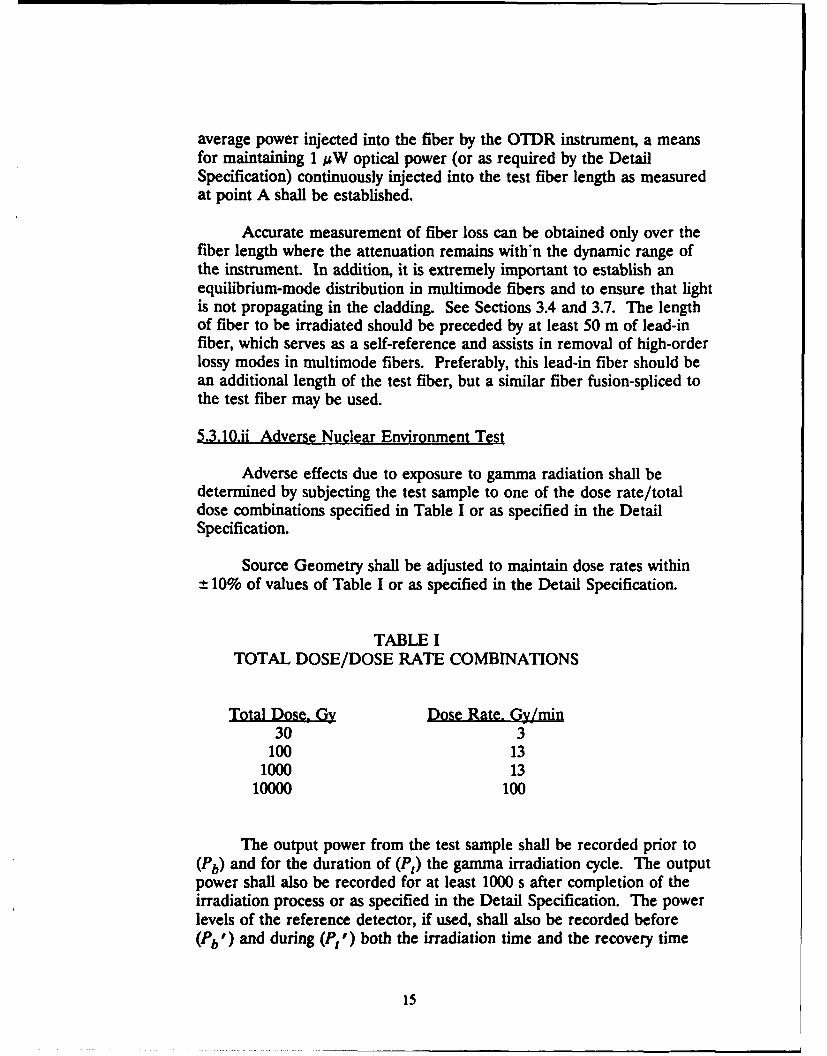
5.3.10.ii Adverse Nuclear Environment Test
Adverse effects due to exposure to gamma radiation shall bedetermined by subjecting the test sample to one of the dose rate/totaldose combinations specified in Table I or as specified in the DetailSpecification.
Source Geometry shall be adjusted to maintain dose rates within±10% of values of Table I or as specified in the Detail Specification.
TABLE ITOTAL DOSE/DOSE RATE COMBINATIONS
Total DosQy Dose Rate. Gy/min30 3
100 131000 13
10000 100
The output power from the test sample shall be recorded prior to(Pb) and for the duration of (P,) the gamma irradiation cycle. The outputpower shall also be recorded for at least 1000 s after completion of theirradiation process or as specified in the Detail Specification. The powerlevels of the reference detector, if used, shall also be recorded before(P,') and during (P, ") both the irradiation time and the recovery time
15
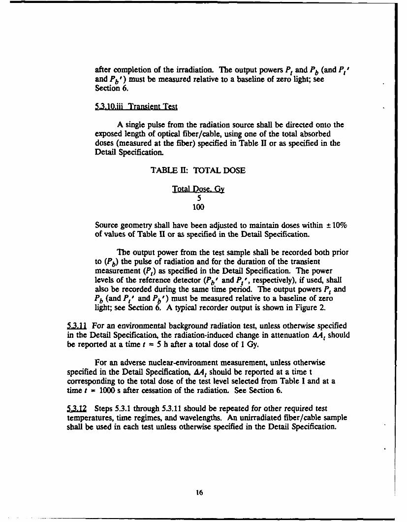
after completion of the irradiation. The output powers P, and Pb (and P,and Pb I) must be measured relative to a baseline of zero light; seeSection 6.
5.3.10.iii Transient Test
A single pulse from the radiation source shall be directed onto theexposed length of optical fiber/cable, using one of the total absorbeddoses (measured at the fiber) specified in Table II or as specified in theDetail Specification.
TABLE HI: TOTAL DOSE
Total Dose, Gy5
100
Source geometry shall have been adjusted to maintain doses within ± 10%of values of Table I or as specified in the Detail Specification.
The output power from the test sample shall be recorded both priorto (Pb) the pulse of radiation and for the duration of the transientmeasurement (P,) as specified in the Detail Specification. The powerlevels of the reference detector (Pb' and P 1', respectively), if used, shallalso be recorded during the same time period. The output powers P, andPb (and I and Pb') must be measured relative to a baseline of zerolight; see Section 6. A typical recorder output is shown in Figure 2.
.. 1 For an environmental background radiation test, unless otherwise specifiedin the Detail Specification, the radiation-induced change in attenuation AA, shouldbe reported at a time t = 5 h after a total dose of 1 Gy.
For an adverse nuclear-environment measurement, unless otherwisespecified in the Detail Specification, AA, should be reported at a time tcorresponding to the total dose of the test level selected from Table I and at atime t = 1000 s after cessation of the radiation. See Section 6.
5.3J2 Steps 53.1 through 53.11 should be repeated for other required testtemperatures, time regimes, and wavelengths. An unirradiated fiber/cable sampleshall be used in each test unless otherwise specified in the Detail Specification.
16
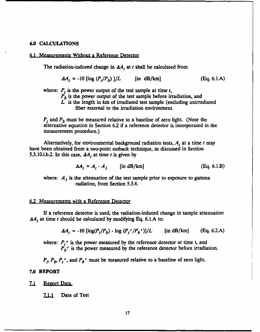
6.0 CALCULATIONS
6.1 Measurements Without a Reference Detector
The radiation-induced change in AA, at t shall be calculated from
AA = -10 [log (Pt/Pb) I/L [in dB/km] (Eq. 6.1A)
where: P, is the power output of the test sample at time t,Pb is the power output of the test sample before irradiation, andL is the length in km of irradiated test sample (excluding unirradiated
fiber external to the irradiation environment.
P, and Pb must be measured relative to a baseline of zero light. (Note thealternative equation in Section 6.2 if a reference detector is incorporated in themeasurement procedure.)
Alternatively, for environmental background radiation tests, A, at a time t mayhave been obtained from a two-point cutback technique, as discussed in Section5.3.10.i.b.2. In this case, AA, at time t is given by
dA1 = At - A1 [in dB/km] (Eq. 6.1.B)
where: A, is the attenuation of the test sample prior to exposure to gammaradiation, from Section 5.3.4.
6.2 Measurements with a Reference Detector
If a reference detector is used, the radiation-induced change in sample attenuationAA, at time t should be calculated by modifying Eq. 6.1A to:
AA t = -10 [log(Pt/Pb) - log (Pt'/Pb')]/L [in dB/kmj (Eq. 6.2A)
where: P," is the power measured by the reference detector at time t, andPb" is the power measured by the reference detector before irradiation.
"t, Pb, Pt1, and Pb" must be measured relative to a baseline of zero light.
7.0 REPORT
2L1 Date of Test
17

212 Title of test.2,U Length of test sample exposed to radiation.
1.A Test wavelength.2,U Test temperature2,1U Test reel diameter, composition, and geometry.2L2 Change in attenuation AA,
2.12i Environmental background steady state test: after t = 5 h and 1Gy total dose.7.1.7i Adverse environment steady state test: after time t correspondingto the specified total dose and t = 1000 s after cessation of irradiation.2J2.iii Transient test: for times specified in the Detail Specification.
2L8 Reference detector characteristics, if used..1.2 Method used to determine input power if different from Section 5.3.6.
2,..1 Characteristics of test sample: fiber/cable type, dimensions, andcomposition.
7..1 Recorder output data.2,.2 Description of radiation source, including energy and type.7.zU Test dose, dose rate (steady state), and time duration of test pulse
(transient)..LI Description of dosimeters and dosimetry procedures.
7.1J.1 Description of optical source.7.16 Description of input and output optical filters or monochromators.2.L12 Description of cladding mode stripper.7J.1 Description of input launch simulator and launch conditions used.2.1.2 Description of any optical splitter used.21.20 Description of detection and recording system.71.21 Documentation of detector/recorder system bandwidth. (Not required for
steady state tests.)7.L22 System stability and background test data.2.123 Description of characteristics of temperature chamber.2,24 Date of calibration of test equipment.7.1 Name and signature of Operator.
8.0 SPECIFYING INFORMATION
8.1 Detail Specification
.1 Identification of fiber type and cable typeL1 Request for type of test: environmental background steady state, adverse
nuclear environment steady state, or transient. For transient tests, requestfor dose level and time range of measurement.
L.. Other information pertinent to the tests for which the standardconditions of this Procedure do not match the intended system applicationof the optical fiber and/or optical cable.
18
CD)
ii E eI 0
A ca00
i i4pI 0'
ii i ii ! u.., o. Iu
I~~ .2 0C C.~ -&. E C
Si .0 C O_. 0
-- - - -- -- - -- - - --- - - -- - - -- - - - -- - - J S-0 - "i
i2 V
i i ; ~0 =2 -
a A
I E "IT- .EI
I LL ICD
* i h I I
iI I -
Q .J
C/)
SCd'I ,~ II.
i . . . . .. .. . ...... ...-- "I19 I Ii Ii
* LL
19
A
CC
.C g UsI-e
_ - 0 .E 0,04
ZI .0-- o-
, I-0.0. I
£00
-------------
1E
-- _ _ ____Cu
10 01
200
~ I-
Ci
1*o
V- go0
CDCL
.8AO JS~ In U;
- 01