Embed Size (px)
Citation preview
ATV900 DC Bus Sharing
Technical Note
06/2019
This document describes how to design applications using ATV900 series drives on a common DC bus

PHA25028.02 06/2019 1
The information provided in this documentation contains general descriptions and/or technical characteristics
of the performance of the products contained herein. This documentation is not intended as a
substitute for and is not to be used for determining suitability or reliability of these products for specific user
applications. It is the duty of any such user or integrator to perform the appropriate and complete risk
analysis, evaluation and testing of the products with respect to the relevant specific application or use
thereof. Neither Schneider Electric nor any of its affiliates or subsidiaries shall be responsible or liable for
misuse of the information contained herein. If you have any suggestions for improvements or amendments
or have found errors in this publication, please notify us.
You agree not to reproduce, other than for your own personal, noncommercial use, all or part of this
document on any medium whatsoever without permission of Schneider Electric, given in writing. You also
agree not to establish any hypertext links to this document or its content. Schneider Electric does not grant
any right or license for the personal and noncommercial use of the document or its content, except for a
non-exclusive license to consult it on an "as is" basis, at your own risk. All other rights are reserved.
All pertinent state, regional, and local safety regulations must be observed when installing and using this
product. For reasons of safety and to help ensure compliance with documented system data, only the
manufacturer should perform repairs to components.
When devices are used for applications with technical safety requirements, the relevant instructions must
be followed.
Failure to use Schneider Electric software or approved software with our hardware products may result in
injury, harm, or improper operating results.
Failure to observe this information can result in injury or equipment damage.
© 2019 Schneider Electric. All rights reserved.
PHA25028.02 06/2019 2
Table of Contents Table of Contents ............................................................................................................................................... 2
Safety Information .............................................................................................................................................. 3
NOTICE ......................................................................................................................................................... 3
PLEASE NOTE .............................................................................................................................................. 3
Qualification Of Personnel ............................................................................................................................. 4
Intended Use ................................................................................................................................................. 4
Product Related Information .......................................................................................................................... 4
About the book .................................................................................................................................................... 8
Related document ......................................................................................................................................... 8
Terminology ................................................................................................................................................... 8
Preamble ............................................................................................................................................................. 9
General instructions when using a common DC link .................................................................................... 10
Input voltage ................................................................................................................................................ 10
Short circuit detection .................................................................................................................................. 10
Disconnection from the DC bus. .................................................................................................................. 10
Input phase loss .......................................................................................................................................... 10
Ground fault detection ................................................................................................................................. 10
EMC............................................................................................................................................................. 10
Group definition for drives association ......................................................................................................... 10
Wiring .......................................................................................................................................................... 11
Drives supplied by the AC mains .................................................................................................................... 12
Drives supplied by the DC terminals .............................................................................................................. 13
Drives supplied by the DC outputs of another drive ......................................................................................... 13
Drive supplied by a DC power supply .............................................................................................................. 14
Using a braking unit on a common DC bus. .................................................................................................. 16
Braking resistor. ............................................................................................................................................... 16
Regenerative braking unit. ............................................................................................................................... 19
Fuses table ........................................................................................................................................................ 21
IEC fuses table ................................................................................................................................................ 21
UL fuses table.................................................................................................................................................. 23
DC switch-disconnector. ................................................................................................................................. 25
Line chokes ....................................................................................................................................................... 27
External soft-charge circuit for drives of groups x2 ..................................................................................... 29
Wiring Options .................................................................................................................................................. 31
Wiring blocks ................................................................................................................................................... 31
PHA25028.02 06/2019 3
Safety Information
Important Information
NOTICE
Read these instructions carefully, and look at the equipment to become familiar with the device before
trying to install, operate, or maintain it. The following special messages may appear throughout this
documentation or on the equipment to inform of potential hazards or to call attention to information that
clarifies or simplifies a procedure.
The addition of this symbol to a Danger safety label indicates that an electrical hazard exists, which will result in personal injury if the instructions are not followed.
This is the safety alert symbol. It is used to alert you to potential personal injury hazards. Obey all safety messages that follow this symbol to avoid possible injury or death.
DANGER
DANGER indicates a hazardous situation which, if not avoided, will result in death or serious injury.
WARNING
WARNING indicates a hazardous situation which, if not avoided, could result in death or serious injury.
CAUTION
CAUTION indicates a hazardous situation which, if not avoided, could result in minor or moderate injury.
NOTICE
NOTICE is used to address practices not related to physical injury.
PLEASE NOTE
Electrical equipment should be installed, operated, serviced, and maintained only by qualified
personnel. No responsibility is assumed by Schneider Electric for any consequences arising out of the
use of this material.
A qualified person is one who has skills and knowledge related to the construction and operation of
electrical equipment and its installation, and has received safety training to recognize and avoid the
hazards involved.
PHA25028.02 06/2019 4
Qualification Of Personnel
Only appropriately trained persons who are familiar with and understand the contents of this manual
and all other pertinent product documentation are authorized to work on and with this product. In
addition, these persons must have received safety training to recognize and avoid hazards involved.
These persons must have sufficient technical training, knowledge and experience and be able to
foresee and detect potential hazards that may be caused by using the product, by changing the settings
and by the mechanical, electrical and electronic equipment of the entire system in which the product is
used. All persons working on and with the product must be fully familiar with all applicable standards,
directives, and accident prevention regulations when performing such work.
Intended Use
This product is a drive for three-phase synchronous, asynchronous motors and intended for industrial
use according to this manual. The product may only be used in compliance with all applicable safety
standard and local regulations and directives, the specified requirements and the technical data. The
product must be installed outside the hazardous ATEX zone. Prior to using the product, you must
perform a risk assessment in view of the planned application. Based on the results, the appropriate
safety measures must be implemented. Since the product is used as a component in an entire system,
you must ensure the safety of persons by means of the design of this entire system (for example,
machine design). Any use other than the use explicitly permitted is prohibited and can result in hazards.
Product Related Information
Read and understand these instructions before performing any procedure with this drive.
DANGER HAZARD OF ELECTRIC SHOCK, EXPLOSION OR ARC FLASH
• Only appropriately trained persons who are familiar with and understand the contents of this manual and all other pertinent product documentation and who have received safety training to recognize and avoid hazards involved are authorized to work on and with this drive system. Installation, adjustment, repair and maintenance must be performed by qualified personnel.
• The system integrator is responsible for compliance with all local and national electrical code requirements as well as all other applicable regulations with respect to grounding of all equipment.
• Many components of the product, including the printed circuit boards, operate with mains voltage.
• Only use properly rated, electrically insulated tools and measuring equipment.
• Do not touch unshielded components or terminals with voltage present.
• Motors can generate voltage when the shaft is rotated. Prior to performing any type of work on the drive system, block the motor shaft to prevent rotation.
• AC voltage can couple voltage to unused conductors in the motor cable. Insulate both ends of unused conductors of the motor cable.
• Do not short across the DC bus terminals or the DC bus capacitors or the braking resistor terminals.
• Before performing work on the drive system: o Disconnect all power, including external control power that may be present. Take into account that circuit breaker or main switch does not de-energize all circuits. o Place a Do Not Turn On label on all power switches related to the drive system. o Lock all power switches in the open position. o Wait 15 minutes to allow the DC bus capacitors to discharge. o Follow the instructions given in the chapter "Verifying the Absence of Voltage" in the installation manual of the product.
• Before applying voltage to the drive system: o Verify that the work has been completed and that the entire installation cannot cause hazards. o If the mains input terminals and the motor output terminals have been grounded and short-circuited, remove the ground and the short circuits on the mains input terminals and the motor output terminals. o Verify proper grounding of all equipment.
o Verify that all protective equipment such as covers, doors, grids is installed and/or closed
Failure to follow these instructions will result in death or serious injury.
Damaged products or accessories may cause electric shock or unanticipated equipment operation.
PHA25028.02 06/2019 5
DANGER ELECTRIC SHOCK OR UNANTICIPATED EQUIPMENT OPERATION
Do not use damaged products or accessories.
Failure to follow these instructions will result in death or serious injury.
Contact your local Schneider Electric sales office if you detect any damage whatsoever.
This equipment has been designed to operate outside of any hazardous location. Only install this
equipment in zones known to be free of hazardous atmosphere.
DANGER POTENTIAL FOR EXPLOSION
Install and use this equipment in non-hazardous locations only.
Failure to follow these instructions will result in death or serious injury.
Your application consists of a whole range of different interrelated mechanical, electrical, and electronic
components, the drive being just one part of the application. The drive by itself is neither intended to nor
capable of providing the entire functionality to meet all safety-related requirements that apply to your
application. Depending on the application and the corresponding risk assessment to be conducted by
you, a whole variety of additional equipment is required such as, but not limited to, external encoders,
external brakes, external monitoring devices, guards, etc.
As a designer/manufacturer of machines, you must be familiar with and observe all standards that apply
to your machine. You must conduct a risk assessment and determine the appropriate Performance
Level (PL) and/or Safety Integrity Level (SIL) and design and build your machine in compliance with all
applicable standards. In doing so, you must consider the interrelation of all components of the machine.
In addition, you must provide instructions for use that enable the user of your machine to perform any
type of work on and with the machine such as operation and maintenance in a safe manner.
The present document assumes that you are fully aware of all normative standards and requirements that apply to your application. Since the drive cannot provide all safety-related functionality for your entire application, you must ensure that the required Performance Level and/or Safety Integrity Level is reached by installing all necessary additional equipment.
WARNING INSUFFICIENT PERFORMANCE LEVEL/SAFETY INTEGRITY LEVEL AND/OR UNINTENDED EQUIPMENT OPERATION
• Conduct a risk assessment according to EN ISO 12100 and all other standards that apply to your application.
• Use redundant components and/or control paths for all critical control functions identified in your risk assessment.
• If moving loads can result in hazards, for example, slipping or falling loads, operate the drive in closed loop mode.
• Verify that the service life of all individual components used in your application is sufficient for the intended service life of your overall application.
• Perform extensive commissioning tests for all potential error situations to verify the effectiveness of the safety-related functions and monitoring functions implemented, for example, but not limited to, speed monitoring by means of encoders, short circuit monitoring for all connected equipment, correct operation of brakes and guards.
• Perform extensive commissioning tests for all potential error situations to verify that the load can be brought to a safe stop under all conditions
Failure to follow these instructions can result in death, serious injury, or equipment damage.
A specific application note NHA80973 is available on hoisting machines and can be downloaded on
www.se.com.
PHA25028.02 06/2019 6
Drive systems may perform unexpected movements because of incorrect wiring, incorrect settings,
incorrect data or other errors.
WARNING UNANTICIPATED EQUIPMENT OPERATION
• Carefully install the wiring in accordance with the EMC requirements.
• Do not operate the product with unknown or unsuitable settings or data.
• Perform a comprehensive commissioning test.
Failure to follow these instructions can result in death, serious injury, or equipment damage.
WARNING LOSS OF CONTROL
• The designer of any control scheme must consider the potential failure modes of control paths and, for critical control functions, provide a means to achieve a safe state during and after a path failure. Examples of critical control functions are emergency stop, overtravel stop, power outage and restart.
• Separate or redundant control paths must be provided for critical control functions.
• System control paths may include communication links. Consideration must be given to the implications of unanticipated transmission delays or failures of the link.
• Observe all accident prevention regulations and local safety guidelines (1).
• Each implementation of the product must be individually and thoroughly tested for proper operation before being placed into service. Failure to follow these instructions can result in death, serious injury, or equipment damage.
Failure to follow these instructions can result in death, serious injury, or equipment damage.
(1) For USA: Additional information, refer to NEMA ICS 1.1 (latest edition), Safety Guidelines for the
Application, Installation, and Maintenance of Solid State Control and to NEMA ICS 7.1 (latest edition),
Safety Standards for Construction and Guide for Selection, Installation and Operation of Adjustable-
Speed Drive Systems.
The temperature of the products described in this manual may exceed 80 °C (176 °F) during operation.
WARNING HOT SURFACES
• Ensure that any contact with hot surfaces is avoided.
• Do not allow flammable or heat-sensitive parts in the immediate vicinity of hot surfaces.
• Verify that the product has sufficiently cooled down before handling it.
• Verify that the heat dissipation is sufficient by performing a test run under maximum load conditions.
Failure to follow these instructions can result in death, serious injury, or equipment damage.
Machines, controllers, and related equipment are usually integrated into networks. Unauthorized
persons and malware may gain access to the machine as well as to other devices on the
network/fieldbus of the machine and connected networks via insufficiently secure access to software
and networks.
PHA25028.02 06/2019 7
WARNING UNAUTHORIZED ACCESS TO THE MACHINE VIA SOFTWARE AND NETWORKS
• In your hazard and risk analysis, consider all hazards that result from access to and operation on the network/fieldbus and develop an appropriate cyber security concept.
• Verify that the hardware infrastructure and the software infrastructure into which the machine is integrated as well as all organizational measures and rules covering access to this infrastructure consider the results of the hazard and risk analysis and are implemented according to best practices and standards covering IT security and cyber security (such as: ISO/IEC 27000 series, Common
• Criteria for Information Technology Security Evaluation, ISO/ IEC 15408, IEC 62351, ISA/IEC 62443, NIST Cybersecurity Framework, Information Security Forum - Standard of Good Practice for Information Security).
• Verify the effectiveness of your IT security and cyber security systems using appropriate, proven methods.
Failure to follow these instructions can result in death, serious injury, or equipment damage.
WARNING LOSS OF CONTROL
• Perform a comprehensive commissioning test to verify that communication monitoring properly detects communication interruptions.
Failure to follow these instructions can result in death, serious injury, or equipment damage.
NOTICE DESTRUCTION DUE TO INCORRECT MAINS VOLTAGE
Before switching on and configuring the product, verify that it is approved for the mains voltage.
Failure to follow these instructions can result in equipment damage.
PHA25028.02 06/2019 8
About the book
Related document
Use your tablet or your PC to quickly access detailed and comprehensive information on all our products on
www.schneider-electric.com.
The internet site provides the information you need for products and solutions
• The whole catalog for detailed characteristics and selection guides
• The CAD files to help design your installation, available in over 20 different file formats
• All software and firmware to maintain your installation up to date
• A large quantity of White Papers, Environment documents, Application solutions, Specifications... to gain a
better understanding of our electrical systems and equipment or automation
• And finally all the User Guides related to your drive, listed below:
You can download these technical publications and other technical information from our website at
http://download.schneider-electric.com
Terminology
The technical terms, terminology, and the corresponding descriptions in this manual normally use the terms
or definitions in the relevant standards.
In the area of drive systems this includes, but is not limited to, terms such as error, error message, failure,
fault, fault reset, protection, safe state, safety function, warning, warning message, and so on.
Among others, these standards include:
• IEC 61800 series: Adjustable speed electrical power drive systems
• IEC 61508 Ed.2 series: Functional safety of electrical/electronic/programmable electronic safety-related
• EN 954-1 Safety of machinery - Safety related parts of control systems
• EN ISO 13849-1 & 2 Safety of machinery - Safety related parts of control systems.
• IEC 61158 series: Industrial communication networks - Fieldbus specifications
• IEC 61784 series: Industrial communication networks - Profiles
• IEC 60204-1: Safety of machinery - Electrical equipment of machines - Part 1: General requirements
In addition, the term zone of operation is used in conjunction with the description of specific hazards, and is
defined as it is for a hazard zone or danger zone in the EC Machinery Directive (2006/42/EC) and in ISO
12100-1.
Also see the glossary at the end of this manual.
Title of Documentation Reference Number
ATV930, ATV950 Installation manual NHA80932 (English), NHA80933 (French),
NHA80934 (German), NHA80935 (Spanish),
NHA80936 (Italian), NHA80937 (Chinese),
NHA80932PT (Portuguese), NHA80932TR (Turkish)
ATV900 Programming manual NHA80757 (English), NHA80758 (French),
NHA80759 (German), NHA80760 (Spanish),
NHA80761 (Italian), NHA80762 (Chinese),
NHA80757PT (Portuguese), NHA80757TR (Turkish)
Altivar Regenerative Unit User manual NVE88423 (English)
Altivar Regenerative Unit Sizing Tool NVE94856 (English)
PHA25028.02 06/2019 9
Preamble The document defines the rules to be applied to link ATV900 drives range on a common DC bus. It also gives the
limits of the DC bus connection.
The main target to use a common DC bus is to save energy, as the braking energy of one drive operating in
generator mode can be re-used by another drive operating in motor mode instead of dissipating it in heat into a
braking resistor. It means that the key point to decide to use a DC bus connection is to define the drives cycles.
The DC bus connection has no sense if all drives are all operating in generator mode or in motor mode at
the same time. The first step is to estimate the benefits to use a DC bus connection regarding the drives cycles.
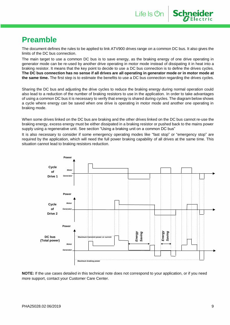
Sharing the DC bus and adjusting the drive cycles to reduce the braking energy during normal operation could
also lead to a reduction of the number of braking resistors to use in the application. In order to take advantages
of using a common DC bus it is necessary to verify that energy is shared during cycles. The diagram below shows
a cycle where energy can be saved when one drive is operating in motor mode and another one operating in
braking mode.
When some drives linked on the DC bus are braking and the other drives linked on the DC bus cannot re-use the
braking energy, excess energy must be either dissipated in a braking resistor or pushed back to the mains power
supply using a regenerative unit. See section “Using a braking unit on a common DC bus”
It is also necessary to consider if some emergency operating modes like “fast stop” or “emergency stop” are
required by the application, which will need the full power braking capability of all drives at the same time. This
situation cannot lead to braking resistors reduction.
NOTE: If the use cases detailed in this technical note does not correspond to your application, or if you need
more support, contact your Customer Care Center.
Power
Power
Power
Motor
Generator
Motor
Generator
Motor
Generator
DC bus
(Total power)
Cycle
of
Drive 2
Cycle
of
Drive 1
En
erg
y
Savin
g
En
erg
y
Savin
g
Maximum transient power or current
Maximum braking power
PHA25028.02 06/2019 10
General instructions when using a common DC link Input voltage
Only drives having the same input voltage range can share the same DC bus. ATV9x0 drives have two mains
voltage ranges:
- 200 / 240 V 3-phase for ATV9x0xxxM3x references,
- 400 / 480 V 3-phase for ATV9x0xxxN4x references.
ATV9x0xxxM3x drives and ATV9x0xxxN4x drives must never share the same DC bus.
Short circuit detection The aim of this detection is to help to protect other drives from an internal DC short-circuit in one of the drives
linked on the common DC link.
Usually, each drive has to be connected to the DC common link by 2 fuses selected in the semi-conductor
protection class, which have the capability to clear a DC current.
Disconnection from the DC bus. To easily disconnect one drive from the DC bus while others are in operation, the drives can be wired to the DC
bus through a DC voltage switch-disconnector as shown in the drawings of this document. This device provides
switch-on and switch-off on the DC-bus and isolation from the DC-bus voltage when it is switched-off to allow the
replacement of the fuses or of the drive.
The DC voltage switch-disconnector to be associated with the drives are listed in the section “SC switch-
disconnector” at the end of this document
Input phase loss Input phase loss fault detection must be enabled on all the drive linked on the DC bus and fed by the AC main
power supply. This is required to avoid that a low power drive to supply all the other though the DC bus link in
case of mains power loss of high power drives.
When a drive is only fed by the DC bus link, the input phase loss fault must be disabled.
Ground fault detection ATV900 ground fault detection does not need to be disabled.
EMC When a common DC bus is used, conducted and radiated disturbances level cannot be at the same level as a
drive alone. The application of the wiring recommendations of this document helps to minimize the increase of
disturbances levels.
Group definition for drives association All ATV900 ratings have an integrated DC choke to reduce the input current harmonics, which will also work as
input currents balancing between drives linked on the same DC bus.
Drives are grouped according to the following table, depending on the characteristics of the input stage
- Input diodes or thyristors rectifier I²t
- Mains input voltage range 200 / 240 V or 400 / 480 V
Refer to the ATV900 installation manual for terminal location
Groups Drives references Input stage
A1 ATV9x0U07N4x … ATV9x0D22N4x 400 V 3-phase, diodes, relay and charge resistor
A2 ATV9x0D30N4x … ATV9x0C31N4x 400 V 3-phase, SCRs/diodes and soft-charge control
B1 ATV9x0U07M3x … ATV9x0D11M3x 200 V 3-phase, diodes, relay and charge resistor
B2 ATV9x0D15M3x … ATV9x0D45M3x 200 V 3-phase, SCRs/diodes and soft-charge control
Drives of groups Ax must never share the same DC bus with drives of groups Bx.
PHA25028.02 06/2019 11
Wiring All ATV9x0 drives are 380 ~ 480 V or 200 ~ 240V, 3-phase AC input voltage. When the drives share the same
DC bus and are supplied at the same time by the mains on L1, L2 and L3 terminals, it must be by the same power
lines after the same mains transformer.
In order to limit the over-voltages on the common DC bus while drives are operating, the following cabling rules
must be respected:
- The total cable length between PA/+ and PC/- connections of one drive to PA/+ and PC/- connections of another drive must be less than 2 m.
- The ground wire included in the DC bus is optional. It is not a protective ground conductor (PE); it just helps to reduce the conducted and radiated emissions.
- The distance between +DC and -DC wires must not exceed 5 cm except close to the junctions’ terminals, the switch-disconnector, the fuses holders or the drives PA/+ and PC/- to allow cabling. This is to avoid over-voltage on the DC link while the drives are operating.
To meet this requirement, it is possible to use one of the following solutions:
Independent cables with cable clamps,
Two or three-wires sheathed cable,
Or 2-wires shielded cable where the shield is grounded.
PHA25028.02 06/2019 12
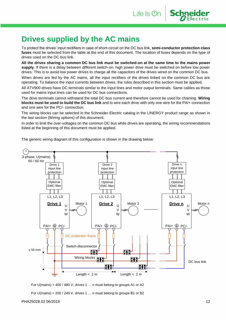
Drives supplied by the AC mains To protect the drives’ input rectifiers in case of short-circuit on the DC bus link, semi-conductor protection class
fuses must be selected from the table at the end of this document. The location of fuses depends on the type of
drives used on the DC bus link.
All the drives sharing a common DC bus link must be switched-on at the same time to the mains power
supply. If there is a delay between different switch-on, high power drive must be switched on before low power
drives. This is to avoid low power drives to charge all the capacitors of the drives wired on the common DC bus.
When drives are fed by the AC mains, all the input rectifiers of the drives linked on the common DC bus are
operating. To balance the input currents between drives, the rules described in this section must be applied.
All ATV900 drives have DC terminals similar to the input lines and motor output terminals. Same cables as those
used for mains input lines can be used for DC bus connections.
The drive terminals cannot withstand the total DC-bus current and therefore cannot be used for chaining. Wiring
blocks must be used to build the DC bus link and to wire each drive with only one wire for the PA/+ connection
and one wire for the PC/- connection.
The wiring blocks can be selected in the Schneider-Electric catalog in the LINERGY product range as shown in
the last section (Wiring options) of this document.
In order to limit the over-voltages on the common DC bus while drives are operating, the wiring recommendations
listed at the beginning of this document must be applied.
The generic wiring diagram of this configuration is shown in the drawing below:
~
Length < 2 m Length < 2 m
DC bus link
Wiring blocks
Drive n
input line
protection
Drive 1
input line
protection
Drive 2
input line
protection
DC protection fuses
≤ 50 mm
Optional
EMC filter
Optional
EMC filterOptional
EMC filter
PA/+ PC/-
L1, L2, L3
U
V
W
Drive n Motor n
PA/+ PC/-
L1, L2, L3
U
V
W
Drive 2 Motor 2
PA/+ PC/-
L1, L2, L3
U
V
W
Drive 1 Motor 1
3-phase, U(mains)
50 / 60 Hz
Switch-disconnector
For U(mains) = 400 / 480 V, drives 1 … n must belong to groups A1 or A2
For U(mains) = 200 / 240 V, drives 1 … n must belong to groups B1 or B2
PHA25028.02 06/2019 13
Drives supplied by the DC terminals In this configuration, the drives are not supplied by the mains power supply, but only through the PA/+ terminal
and the PC/- inputs. The DC source can be one of the following:
- A drive which a part of the power is provided to other drives through the DC bus,
- A dedicated DC power source device to provide DC voltage.
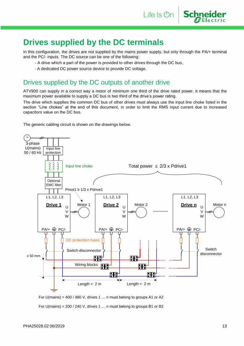
Drives supplied by the DC outputs of another drive
ATV900 can supply in a correct way a motor of minimum one third of the drive rated power. It means that the
maximum power available to supply a DC bus is two third of the drive’s power rating.
The drive which supplies the common DC bus of other drives must always use the input line choke listed in the
section “Line chokes” at the end of this document, in order to limit the RMS input current due to increased
capacitors value on the DC bus.
The generic cabling circuit is shown on the drawings below.
~
Length < 2 m Length < 2 m
Wiring blocks
DC protection fuses
≤ 50 mm
Optional
EMC filter
PA/+ PC/-
L1, L2, L3
U
V
W
Drive n Motor n
PA/+ PC/-
L1, L2, L3
U
V
W
Drive 2 Motor 2
PA/+ PC/-
L1, L2, L3
U
V
W
Drive 1 Motor 1
3-phase
U(mains)
50 / 60 HzInput line
protection
Total power ≤ 2/3 x Pdrive1
Pmot1 ≥ 1/3 x Pdrive1
Input line choke
Switch-disconnector Switch
disconnector
For U(mains) = 400 / 480 V, drives 1 … n must belong to groups A1 or A2
For U(mains) = 200 / 240 V, drives 1 … n must belong to groups B1 or B2
PHA25028.02 06/2019 14
In addition to the general instructions listed at the beginning of this document, the following rules must be
respected:
- The power rating of drive 1 is always the highest power rating of the full system. It must be used at least at one third of its rated power (for example a 90 kW drive must be used at least with a 30 kW motor, which leaves 60 kW to supply drives 2 to n)
- An additional input line choke selected from the list of the section “Line chokes” at the end of this document, is needed only if the total power of drives 2 to n is greater than 25 % of the rated power of drive 1, because of the increase of the total DC capacitor value.
- Drives 2 to n are sorted by power rating: from the highest for drive 2 to the lowest for drive n, to get the
highest wiring impedance on the lowest drive power rating.
- If drives 2 to drives n belong to groups A1 or B1, the internal soft-charge circuits of these drives will limit
the capacitor charge current during switch-on of drive 1.
Drives 2 to n belonging to group A2 or B2, must use the additional external soft-charge circuit as
described in the section at the end of this document, because there is no DC capacitors charge limitation when they are supplied by the DC bus.
- DC fuses on each drive (drive 1 to drive n) have to be defined according to the “Fuses table” section at the end of this document.
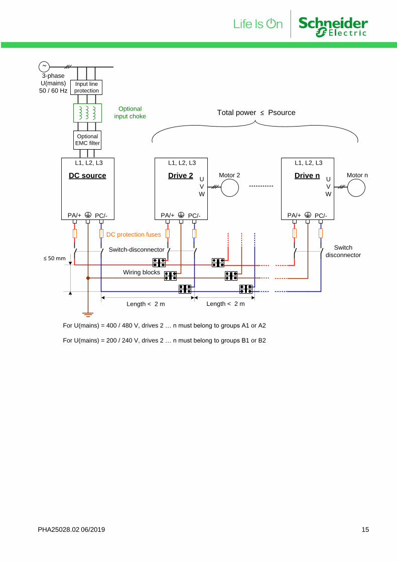
Drive supplied by a DC power supply
The DC power supply replaces the drive which shared a part of its power with the common DC bus in the
configuration of the previous section. The output power rating of the DC source must be greater or equal to the
sum of all drives’ power rating linked on the common DC bus. It has also to provide the transient overload required
by the drives in the application.
The DC source output protection fuses have to be selected according to the DC source user’s manual. If these
data are not provided, the same semiconductors protection class fuses defined for the drive of the same power
rating can be used.
The DC source must guarantee a maximum of 3% DC voltage drop and 5% DC voltage ripple at rated load.
If the DC source is a simple diodes or non-reversible SCR/diodes rectifier, input line chokes or DC output choke
might have to be added to reduce the input line RMS current.
If the DC source is an active front-end which performs also input harmonic current mitigation with or without
regenerative braking capabilities, no additional parts are needed except those needed by the active DC source
itself.
In addition to the generic instructions defined at the beginning of this document, the following additional
requirements must be applied in this case:
- Drives 2 to n are sorted by power rating: from the highest for drive 2 to the lowest for drive n, to get the highest wiring impedance on the lowest drive power rating.
- If drives 2 to drives n belong to groups A1 or B1, the internal soft-charge circuits of these drives will limit the capacitor charge current during switch-on of drive 1.
Drives 2 to n belonging to group A2 or B2, must use the additional external soft-charge circuit as described in the section at the end of this document, because there is no DC capacitors charge limitation when they are supplied by the DC bus.
- DC fuses on each drive (drive 1 to drive n) have to be defined according to the “Fuses table” section at
the end of this document.
PHA25028.02 06/2019 15
~
Length < 2 m Length < 2 m
Wiring blocks
DC protection fuses
≤ 50 mm
Optional
EMC filter
PA/+ PC/-
L1, L2, L3
U
V
W
Drive n Motor n
PA/+ PC/-
L1, L2, L3
U
V
W
Drive 2 Motor 2
PA/+ PC/-
L1, L2, L3
DC source
3-phase
U(mains)
50 / 60 HzInput line
protection
Optional
input chokeTotal power ≤ Psource
Switch-disconnector Switch
disconnector
For U(mains) = 400 / 480 V, drives 2 … n must belong to groups A1 or A2
For U(mains) = 200 / 240 V, drives 2 … n must belong to groups B1 or B2
PHA25028.02 06/2019 16
Using a braking unit on a common DC bus. When some drives sharing a common DC-bus are braking and if the other drives linked on the same DC-bus are
not able to use all this braking energy, the drives’ DC bus capacitors will store this energy. This will lead to an
increase of the DC bus voltage. To avoid any over-braking error on the drives (error code: ObF) a braking unit
can be used. The same solutions as for a single drive can be used:
- braking resistor,
- or regenerative braking unit.
The full knowledge of the application cycles, or the situations which can happen during all drives’ operations is
necessary to define what are the peak and average power, the braking time and the duty cycle.
Braking resistor.
In any of the above described DC-bus sharing configuration, a braking resistor can be used on each drive linked
to the DC-bus, when this feature in included. The braking IGBT integrated in the drives is activated when the DC
bus voltage reaches a defined level. Since the DC-bus voltage is common, any braking IGBT of any drive on the
DC-bus will operate to discharge the DC-bus through the externally connected resistor.
On each drive equipped with a braking resistor, the parameter “brC” must be set to “yes” to enable operation
of the braking IGBT. This will set parameter “brA” to “no” on these drives.
Parameter “brA” can be set in different ways on the other drives sharing the common DC-bus:
- “brA” set to “no” to get the braking performances on drives to follow the deceleration ramp.
- “brA” set to “yes” for drives for which it is not necessary to follow the deceleration ramp.
The calculation of the braking resistor is made in the same way as for a single drive, but the total braking power
on the DC bus must be considered. This includes the maximum steady state braking power and the deceleration
power of all the drive which have the “brA” parameter set to “no”.
This will give the peak power 𝑃𝑝𝑒𝑎𝑘 , the total braking time, the average power 𝑃𝑎𝑣𝑔 and the duty cycle.
Using only one braking resistor The simplest solution is to use only one braking resistor wired on one of the drives sharing the DC bus. This is possible if the calculated peak braking power 𝑃𝑝𝑒𝑎𝑘 and the average braking power 𝑃𝑎𝑣𝑔 are lower than the
capabilities of one of the drives sharing the DC bus. The decision process is the following:
1.Select the drive to be equipped by a braking resistor
The peak braking power 𝑃𝑝𝑒𝑎𝑘 of the system must be dissipated in the braking resistor. To do it, the maximum
resistor value 𝑅𝑚𝑎𝑥 is calculated by
𝑅𝑚𝑎𝑥 =(𝑈𝑏𝑟𝑎𝑘𝑒)²
𝑃𝑝𝑒𝑎𝑘
where 𝑈𝑏𝑟𝑎𝑘𝑒 is the DC bus voltage when the braking IGBT is in use. On ATV900, 𝑈𝑏𝑟𝑎𝑘𝑒 = 780 𝑉 .
The drive selected must accept a minimum braking resistor value 𝑅𝑚𝑖𝑛 lower than 𝑅𝑚𝑎𝑥 in order to be able to
select a resistor value 𝑅 defined by
𝑅𝑚𝑖𝑛 ≤ 𝑅 ≤ 𝑅𝑚𝑎𝑥
The highest power rating drive sharing the DC bus equipped with a braking IGBT can be used to drive the
braking resistor even if it is not this drive which will brake during the application cycle. Even in “ready” state,
ATV900 can activate the braking IGBT if the “brC” parameter is set to “yes” and the “brA” parameter set to “no”.
If no drive on the DC bus has 𝑅𝑚𝑖𝑛 specification verifying 𝑅𝑚𝑖𝑛 ≤ 𝑅𝑚𝑎𝑥 , it is not possible to use only one braking
resistor in the system.
PHA25028.02 06/2019 17
In this case the section “Using more than one braking resistor” later in this document must be considered.
2. Define the braking resistor rated power
The braking torque characteristic and the duty cycle of the application allow to calculate the average braking
power 𝑃𝑎𝑣𝑔. The rated power of the braking resistor 𝑅 must be greater or equal to this average braking power.
The overload factor of the braking resistor must allow to withstand the peak power 𝑃𝑝𝑒𝑎𝑘. The typical braking
cycles defined in the ATV900 catalog can help to select a braking resistor.
Using more than one braking resistor If there is no drive sharing the DC bus having a 𝑅𝑚𝑖𝑛 specification which meet the condition 𝑅𝑚𝑖𝑛 ≤ 𝑅𝑚𝑎𝑥 , it
means that the peak braking power has to be shared by two or more drives depending on the application.
1. Define number and values of braking resistors
The simplest way is to start with the highest power rating drive sharing the DC bus and to define the peak power
𝑃𝑝𝑒𝑎𝑘(𝑅1) that it will be able to dissipate:
𝑃𝑝𝑒𝑎𝑘(𝑅1) =(𝑈𝑏𝑟𝑎𝑘𝑒)²
𝑅1
with 𝑅1 ≥ 𝑅min (1) where 𝑅min (1) is the minimum braking resistor of drive 1.
This has to be continued with the next highest drives’ power ratings to define 𝑅2 ≥ 𝑅min (2) , … 𝑅𝑛 ≥ 𝑅min (𝑛)
with 𝑅2 ≥ 𝑅min (2) where 𝑅min (2) is the minimum braking resistor of drive 2, …
and 𝑅𝑛 ≥ 𝑅min (𝑛) where 𝑅min (𝑛) is the minimum braking resistor of drive n
and to calculate
𝑃𝑝𝑒𝑎𝑘(𝑅2) =(𝑈𝑏𝑟𝑎𝑘𝑒)²
𝑅2 , … 𝑃𝑝𝑒𝑎𝑘(𝑅𝑛) =
(𝑈𝑏𝑟𝑎𝑘𝑒)²
𝑅𝑛
until we get
𝑃𝑝𝑒𝑎𝑘(𝑅1) + 𝑃𝑝𝑒𝑎𝑘(𝑅2) + ⋯ + 𝑃𝑝𝑒𝑎𝑘(𝑅𝑛) ≥ 𝑃𝑝𝑒𝑎𝑘
2. Define braking resistors rated power
The braking torque characteristic and the duty cycle of the application allow to calculate the total average braking power 𝑃𝑎𝑣𝑔 , which must be shared between all the braking resistors. The rated power of each resistor 𝑃𝑎𝑣𝑔(𝑅𝑖)
will be defined with the same ratio to the average braking power as the ratio of the peak power of each resistor to
the total peak power.
The peak power of resistor 𝑖 is
𝑃𝑝𝑒𝑎𝑘(𝑅𝑖) =(𝑈𝑏𝑟𝑎𝑘𝑒)²
𝑅𝑖
The total peak power for all the resistors is
𝑃𝑝𝑒𝑎𝑘 = 𝑃𝑝𝑒𝑎𝑘(𝑅1) + 𝑃𝑝𝑒𝑎𝑘(𝑅2) + ⋯ + 𝑃𝑝𝑒𝑎𝑘(𝑅𝑛) = (𝑈𝑏𝑟𝑎𝑘𝑒)² ∙ (1
𝑅1+
1
𝑅2+ ⋯ +
1
𝑅𝑛)
The ratio 𝑘(𝑅𝑖) of the peak power of resistor 𝑖 to the total peak power is
𝑘(𝑅𝑖) =𝑃𝑝𝑒𝑎𝑘(𝑅𝑖)
𝑃𝑝𝑒𝑎𝑘=
1𝑅𝑖
1𝑅1
+1
𝑅2+ ⋯ +
1𝑅𝑛
The average power of resistor 𝑖 can be calculated by
𝑃𝑎𝑣𝑔(𝑅𝑖) = 𝑘(𝑅𝑖) ∙ 𝑃𝑎𝑣𝑔
PHA25028.02 06/2019 18
Example 1: one braking resistor Let consider the following system of 3 drives sharing the same DC bus:
ATV9x0D15N4 + ATV9x0U75N4 + ATV9x0U40N4
The application is defined by the following
- ATV9x0D15N4 never brakes; it can be running or in “ready” state
- ATV9x0U75N4 and ATV9x0U40N4 are making cycles and can brake both at rated torque at the same time to decelerate their loads from rated speed down to 0 during 3 s every 40 s.
When ATV9x0D15N4 is operating at least at 80% of its rated torque the braking energy of the two other drives is
reused by ATV9x0D15N4.
When ATV9x0D15N4 is in “ready”, the braking energy of ATV9x0U75N4 and ATV9x0U40N4 must be dissipated
in a braking resistor.
To simplify the calculation, we consider 0.9 as the motors efficiency and 0.95 as the drives efficiency. The total
peak power of the system is the sum of the peak power of both drives:
𝑃𝑝𝑒𝑎𝑘 = (7.5 × 0.9 × 0.95) + (4.0 × 0.9 × 0.95) = 6.41 + 3.42 = 9.83 𝑘𝑊
The maximum resistor 𝑅𝑚𝑎𝑥 to get this peak power is
𝑅𝑚𝑎𝑥 =780²
9.83 × 103 = 61.9 Ω
The minimum braking resistor value of ATV900HD15N4 is given in ATV900 installation manual
𝑅𝑚𝑖𝑛 = 16 Ω
The condition 𝑅𝑚𝑖𝑛 ≤ 𝑅𝑚𝑎𝑥 is met. It is possible to select a resistor value between 16 Ω and 61.9 Ω
The two drives are braking by doing a deceleration at constant torque, it means that the power is decreasing
linearly with speed during 3 s and then there is no braking power during 40 s. The average power during one
cycle can be calculated by
𝑃𝑎𝑣𝑔 =1
3 + 40× (
9.83 𝑘𝑊
2× 3 + 0 × 40) = 228.7 𝑊
The reference VW3A7732, 28 Ω, 300 W wired on the ATV9x0D15N4 meets the requirements of this application.
Example 2: two braking resistors Let consider the following system of 7 drives sharing the same DC bus:
ATV9x0U75N4 + ATV9x0U55N4 + 5 x ATV9x0U22N4
The application is defined by the following
- All drives are making acceleration and deceleration cycles.
- The sequences of the drives are synchronized in a way that there are always drives running using enough power when another one is braking. In this case the DC bus sharing is operating.
- Every 75 s all the drives have to stop at the same time, with a braking torque equal to 1.3 times the rated torque of the motor, during 2s to decrease the speed from rates speed down to 0.
The DC bus sharing does not work to achieve the full braking sequence every 75 s. This braking energy has to
be dissipated in braking resistors. Instead of using one braking resistor per drive, it is possible to use less than 7
pieces in this application.
To simplify the calculation, we consider 0.9 as the motors efficiency and 0.95 as the drives efficiency. The total
peak power of the system is the sum of the peak power of all drives:
𝑃𝑝𝑒𝑎𝑘 = (1.3 × 7.5 × 0.9 × 0.95) + (1.3 × 5.5 × 0.9 × 0.95) + 5 × (1.3 × 2.2 × 0.9 × 0.95) = 26.7 𝑘𝑊
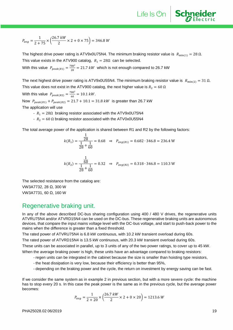
PHA25028.02 06/2019 19
𝑃𝑎𝑣𝑔 =1
2 + 75× (
26.7 𝑘𝑊
2× 2 + 0 × 75) = 346.8 𝑊
The highest drive power rating is ATV9x0U75N4. The minimum braking resistor value is 𝑅min (1) = 28 Ω.
This value exists in the ATV900 catalog, 𝑅1 = 28Ω can be selected.
With this value 𝑃𝑝𝑒𝑎𝑘(𝑅1) =780²
28= 21.7 𝑘𝑊 which is not enough compared to 26.7 kW
The next highest drive power rating is ATV9x0U55N4. The minimum braking resistor value is 𝑅min (2) = 31 Ω.
This value does not exist in the ATV900 catalog, the next higher value is 𝑅2 = 60 Ω
With this value 𝑃𝑝𝑒𝑎𝑘(𝑅2) =780²
60= 10.1 𝑘𝑊.
Now 𝑃𝑝𝑒𝑎𝑘(𝑅1) + 𝑃𝑝𝑒𝑎𝑘(𝑅2) = 21.7 + 10.1 = 31.8 𝑘𝑊 is greater than 26.7 kW
The application will use
- 𝑅1 = 28Ω braking resistor associated with the ATV9x0U75N4
- 𝑅2 = 60 Ω braking resistor associated with the ATV0x0U55N4
The total average power of the application is shared between R1 and R2 by the following factors:
𝑘(𝑅1) =
128
128 +
160
= 0.68 ⇒ 𝑃𝑎𝑣𝑔(𝑅1) = 0.682 ∙ 346.8 = 236.4 W
𝑘(𝑅2) =
160
128 +
160
= 0.32 ⇒ 𝑃𝑎𝑣𝑔(𝑅2) = 0.318 ∙ 346.8 = 110.3 W
The selected resistance from the catalog are:
VW3A7732, 28 Ω, 300 W
VW3A7731, 60 Ω, 160 W
Regenerative braking unit.
In any of the above described DC-bus sharing configuration using 400 / 480 V drives, the regenerative units
ATVRU75N4 and/or ATVRD15N4 can be used on the DC-bus. These regenerative braking units are autonomous
devices, that compare the input mains voltage level with the DC-bus voltage, and start to push-back power to the
mains when the difference is greater than a fixed threshold.
The rated power of ATVRU75N4 is 6.8 kW continuous, with 10.2 kW transient overload during 60s.
The rated power of ATVRD15N4 is 13.5 kW continuous, with 20.3 kW transient overload during 60s.
These units can be associated in parallel, up to 3 units of any of the two power ratings, to cover up to 45 kW.
When the average braking power is high, these units have an advantage compared to braking resistors:
- regen units can be integrated in the cabinet because the size is smaller than hoisting type resistors,
- the heat dissipation is very low, because their efficiency is better than 95%,
- depending on the braking power and the cycle, the return on investment by energy saving can be fast.
If we consider the same system as in example 2 in previous section, but with a more severe cycle: the machine
has to stop every 20 s. In this case the peak power is the same as in the previous cycle, but the average power
becomes:
𝑃𝑎𝑣𝑔 =1
2 + 20× (
26.7 𝑘𝑊
2× 2 + 0 × 20) = 1213.6 𝑊

PHA25028.02 06/2019 20
This leads to select braking resistors of same value but with higher average power:
VW3A7742, 28 Ω, 1100 W 570 mm x 190 mm x 180 mm
VW3A7741, 60 Ω, 500 W 465 mm x 175 mm x 100 mm
To compare with power regenerative units, the peak power of 26.7 kW is achieved by using
1x ATVRD15N4 399 mm x 235 mm x 105 mm
+ 1x ATVRU75N4 337 mm x 175 mm x 80 mm
The two units are wired in parallel, which gives a total of 30.5 kW transient power, more than enough average
power, with smaller overall dimensions.
Taking into account a global efficiency of the two regen units of 95% and assuming 8 hours per days, 220 days
per year of the system operation, the total energy saved per year is:
𝐸𝑠𝑎𝑣𝑒𝑑 = 1213.6 × 0.95 × 8 × 220 = 2029.3 𝑘𝑊ℎ
Depending on the local energy cost and the buying price difference between the two resistors and the two regen
units it is easy to calculate the return on investment of the regen solution.
PHA25028.02 06/2019 21
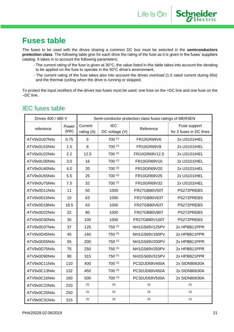
Fuses table The fuses to be used with the drives sharing a common DC bus must be selected in the semiconductors
protection class. The following table give for each drive the rating of the fuse as it is given in the fuses’ suppliers
catalog. It takes in to account the following parameters:
- The current rating of the fuse is given at 30°C, the value listed in this table takes into account the derating to be applied on the fuse to operate in the 50°C drive’s environment,
- The current rating of the fuse takes also into account the drives overload (1.5 rated current during 60s)
and the thermal cycling when the drive is running or stopped.
To protect the input rectifiers of the drives two fuses must be used: one fuse on the +DC line and one fuse on the
–DC line.
IEC fuses table
Drives 400 / 480 V Semi-conductor protection class fuses ratings of MERSEN
reference Power
(kW)
Current
rating (A)
IEC
DC voltage (V) Reference
Fuse support
for 2 fuses in DC lines
ATV9x0U07N4x 0.75 6 700 (1) FR10GR69V6 2x US101IHEL
ATV9x0U15N4x 1.5 8 700 (1) FR10GR69V8 2x US101IHEL
ATV9x0U22N4x 2.2 12.5 700 (1) FR10GR69V12.5 2x US101IHEL
ATV9x0U30N4x 3.0 16 700 (1) FR10GR69V16 2x US101IHEL
ATV9x0U40N4x 4.0 20 700 (1) FR10GR69V20 2x US101IHEL
ATV9x0U55N4x 5.5 25 700 (1) FR10GR69V25 2x US101IHEL
ATV9x0U75N4x 7.5 32 700 (1) FR10GR69V32 2x US101IHEL
ATV9x0D11N4x 11 50 1000 FR27GB80V50T PS272PREBS
ATV9x0D15N4x 15 63 1000 FR27GB80V63T PS272PREBS
ATV9x0D18N4x 18.5 63 1000 FR27GB80V63T PS272PREBS
ATV9x0D22N4x 22 80 1000 FR27GB80V80T PS272PREBS
ATV9x0D30N4x 30 100 1000 FR27GB80V100T PS272PREBS
ATV9x0D37N4x 37 125 750 (1) NH1GS69V125PV 2x HPBB11PPR
ATV9x0D45N4x 45 160 750 (1) NH1GS69V160PV 2x HPBB11PPR
ATV9x0D55N4x 55 200 750 (1) NH1GS69V200PV 2x HPBB11PPR
ATV9x0D75N4x 75 250 750 (1) NH1GS69V250PV 2x HPBB11PPR
ATV9x0D90N4x 90 315 750 (1) NH2GS69V315PV 2x HPBB21PPR
ATV9x0C11N4x 110 400 700 (1) PC32UD69V400A 2x SIDN80630A
ATV9x0C13N4x 132 450 700 (1) PC32UD69V450A 2x SIDN80630A
ATV9x0C16N4x 160 500 700 (1) PC32UD69V500A 2x SIDN80630A
ATV9x0C22N4x 220 (3) (3) (3) (3)
ATV9x0C25N4x 250 (3) (3) (3) (3)
ATV9x0C31N4x 315 (3) (3) (3) (3)
PHA25028.02 06/2019 22
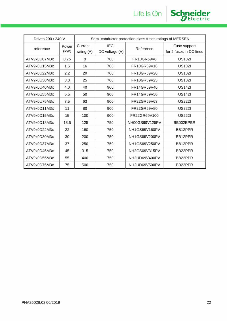
Drives 200 / 240 V Semi-conductor protection class fuses ratings of MERSEN
reference Power
(kW)
Current
rating (A)
IEC
DC voltage (V) Reference
Fuse support
for 2 fuses in DC lines
ATV9x0U07M3x 0.75 8 700 FR10GR69V8 US102I
ATV9x0U15M3x 1.5 16 700 FR10GR69V16 US102I
ATV9x0U22M3x 2.2 20 700 FR10GR69V20 US102I
ATV9x0U30M3x 3.0 25 700 FR10GR69V25 US102I
ATV9x0U40M3x 4.0 40 900 FR14GR69V40 US142I
ATV9x0U55M3x 5.5 50 900 FR14GR69V50 US142I
ATV9x0U75M3x 7.5 63 900 FR22GR69V63 US222I
ATV9x0D11M3x 11 80 900 FR22GR69V80 US222I
ATV9x0D15M3x 15 100 900 FR22GR69V100 US222I
ATV9x0D18M3x 18.5 125 750 NH00GS69V125PV BB002EPBR
ATV9x0D22M3x 22 160 750 NH1GS69V160PV BB12PPR
ATV9x0D30M3x 30 200 750 NH1GS69V200PV BB12PPR
ATV9x0D37M3x 37 250 750 NH1GS69V250PV BB12PPR
ATV9x0D45M3x 45 315 750 NH2GS69V315PV BB22PPR
ATV9x0D55M3x 55 400 750 NH2UD69V400PV BB22PPR
ATV9x0D75M3x 75 500 750 NH2UD69V500PV BB22PPR
PHA25028.02 06/2019 23
UL fuses table
Drives 400 / 480 V Semi-conductor protection class fuses ratings of MERSEN
reference Power
(kW)
Current
rating (A)
UL
DC voltage (V) Reference
Fuse support
for 2 fuses in DC lines
ATV9x0U07N4x 0.75 6 1000 DCT6-2 2x US101IHEL
ATV9x0U15N4x 1.5 8 1000 DCT8-2 2x US101IHEL
ATV9x0U22N4x 2.2 12 1000 DCT12-2 2x US101IHEL
ATV9x0U30N4x 3.0 15 1000 DCT15-2 2x US101IHEL
ATV9x0U40N4x 4.0 20 1000 DCT20-2 2x US101IHEL
ATV9x0U55N4x 5.5 25 1000 DCT25-2 2x US101IHEL
ATV9x0U75N4x 7.5 30 1000 DCT30-2 2x US101IHEL
ATV9x0D11N4x 11 50 950 (1) HSJ50 PS272PREBS
ATV9x0D15N4x 15 60 950 (1) HSJ60 PS272PREBS
ATV9x0D18N4x 18.5 60 950 (1) HSJ60 PS272PREBS
ATV9x0D22N4x 22 110 950 (1) HSJ110 (2) 2x 62001HPJ
ATV9x0D30N4x 30 110 950 (1) HSJ110 (2) 2x 62001HPJ
ATV9x0D37N4x 37 125 950 (1) HSJ125 2x 62001HPJ
ATV9x0D45N4x 45 150 950 (1) HSJ150 2x 62001HPJ
ATV9x0D55N4x 45 200 950 (1) HSJ200 2x 62001HPJ
ATV9x0D75N4x 55 250 950 (1) HSJ250 2x 64031HPJ
ATV9x0D90N4x 75 350 950 (1) HSJ350 2x 64031HPJ
ATV9x0C11N4x 110 400 950 (1) HSJ400 2x 64031HPJ
ATV9x0C13N4x 132 450 950 (1) HSJ450 2x 6631HPJ
ATV9x0C16N4x 160 500 950 (1) HSJ500 2x 6631HPJ
ATV9x0C22N4x 220 (3) (3) (3) (3)
ATV9x0C25N4x 250 (3) (3) (3) (3)
ATV9x0C31N4x 315 (3) (3) (3) (3)
PHA25028.02 06/2019 24
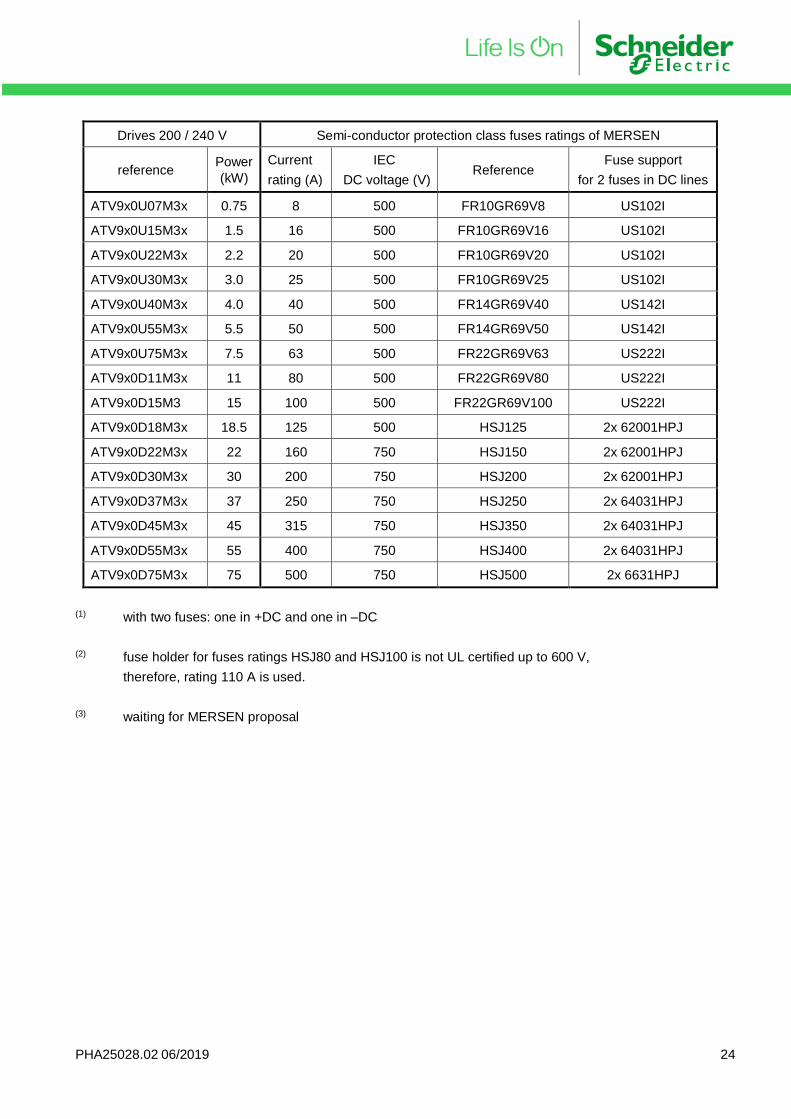
Drives 200 / 240 V Semi-conductor protection class fuses ratings of MERSEN
reference Power
(kW)
Current
rating (A)
IEC
DC voltage (V) Reference
Fuse support
for 2 fuses in DC lines
ATV9x0U07M3x 0.75 8 500 FR10GR69V8 US102I
ATV9x0U15M3x 1.5 16 500 FR10GR69V16 US102I
ATV9x0U22M3x 2.2 20 500 FR10GR69V20 US102I
ATV9x0U30M3x 3.0 25 500 FR10GR69V25 US102I
ATV9x0U40M3x 4.0 40 500 FR14GR69V40 US142I
ATV9x0U55M3x 5.5 50 500 FR14GR69V50 US142I
ATV9x0U75M3x 7.5 63 500 FR22GR69V63 US222I
ATV9x0D11M3x 11 80 500 FR22GR69V80 US222I
ATV9x0D15M3 15 100 500 FR22GR69V100 US222I
ATV9x0D18M3x 18.5 125 500 HSJ125 2x 62001HPJ
ATV9x0D22M3x 22 160 750 HSJ150 2x 62001HPJ
ATV9x0D30M3x 30 200 750 HSJ200 2x 62001HPJ
ATV9x0D37M3x 37 250 750 HSJ250 2x 64031HPJ
ATV9x0D45M3x 45 315 750 HSJ350 2x 64031HPJ
ATV9x0D55M3x 55 400 750 HSJ400 2x 64031HPJ
ATV9x0D75M3x 75 500 750 HSJ500 2x 6631HPJ
(1) with two fuses: one in +DC and one in –DC
(2) fuse holder for fuses ratings HSJ80 and HSJ100 is not UL certified up to 600 V,
therefore, rating 110 A is used.
(3) waiting for MERSEN proposal
PHA25028.02 06/2019 25
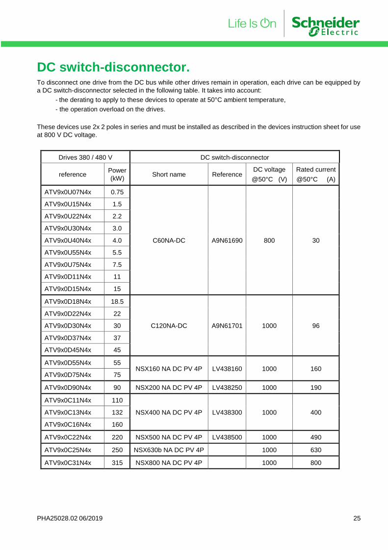
DC switch-disconnector. To disconnect one drive from the DC bus while other drives remain in operation, each drive can be equipped by
a DC switch-disconnector selected in the following table. It takes into account:
- the derating to apply to these devices to operate at 50°C ambient temperature,
- the operation overload on the drives.
These devices use 2x 2 poles in series and must be installed as described in the devices instruction sheet for use
at 800 V DC voltage.
Drives 380 / 480 V DC switch-disconnector
reference Power
(kW) Short name Reference
DC voltage
@50°C (V)
Rated current
@50°C (A)
ATV9x0U07N4x 0.75
C60NA-DC A9N61690 800 30
ATV9x0U15N4x 1.5
ATV9x0U22N4x 2.2
ATV9x0U30N4x 3.0
ATV9x0U40N4x 4.0
ATV9x0U55N4x 5.5
ATV9x0U75N4x 7.5
ATV9x0D11N4x 11
ATV9x0D15N4x 15
ATV9x0D18N4x 18.5
C120NA-DC A9N61701 1000 96
ATV9x0D22N4x 22
ATV9x0D30N4x 30
ATV9x0D37N4x 37
ATV9x0D45N4x 45
ATV9x0D55N4x 55 NSX160 NA DC PV 4P LV438160 1000 160
ATV9x0D75N4x 75
ATV9x0D90N4x 90 NSX200 NA DC PV 4P LV438250 1000 190
ATV9x0C11N4x 110
NSX400 NA DC PV 4P LV438300 1000 400 ATV9x0C13N4x 132
ATV9x0C16N4x 160
ATV9x0C22N4x 220 NSX500 NA DC PV 4P LV438500 1000 490
ATV9x0C25N4x 250 NSX630b NA DC PV 4P 1000 630
ATV9x0C31N4x 315 NSX800 NA DC PV 4P 1000 800
PHA25028.02 06/2019 26
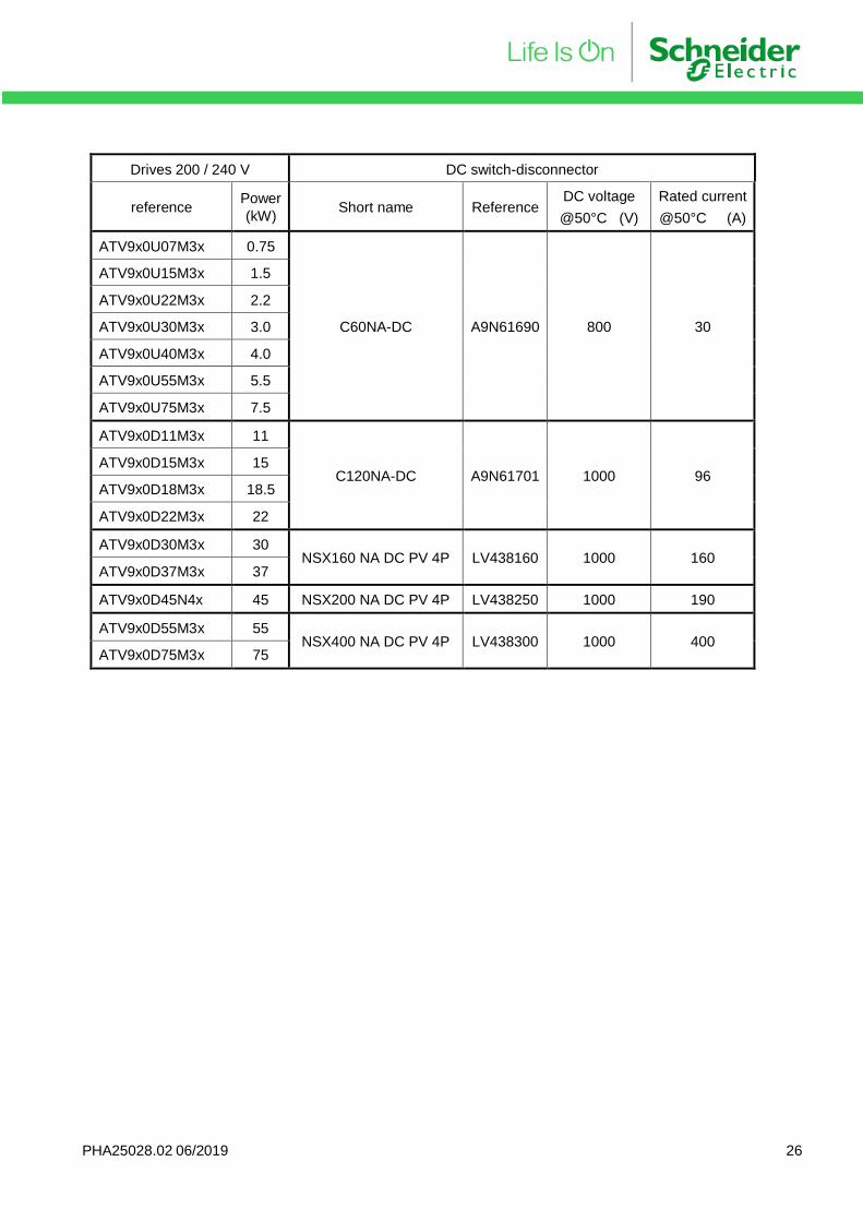
Drives 200 / 240 V DC switch-disconnector
reference Power
(kW) Short name Reference
DC voltage
@50°C (V)
Rated current
@50°C (A)
ATV9x0U07M3x 0.75
C60NA-DC A9N61690 800 30
ATV9x0U15M3x 1.5
ATV9x0U22M3x 2.2
ATV9x0U30M3x 3.0
ATV9x0U40M3x 4.0
ATV9x0U55M3x 5.5
ATV9x0U75M3x 7.5
ATV9x0D11M3x 11
C120NA-DC A9N61701 1000 96 ATV9x0D15M3x 15
ATV9x0D18M3x 18.5
ATV9x0D22M3x 22
ATV9x0D30M3x 30 NSX160 NA DC PV 4P LV438160 1000 160
ATV9x0D37M3x 37
ATV9x0D45N4x 45 NSX200 NA DC PV 4P LV438250 1000 190
ATV9x0D55M3x 55 NSX400 NA DC PV 4P LV438300 1000 400
ATV9x0D75M3x 75
PHA25028.02 06/2019 27
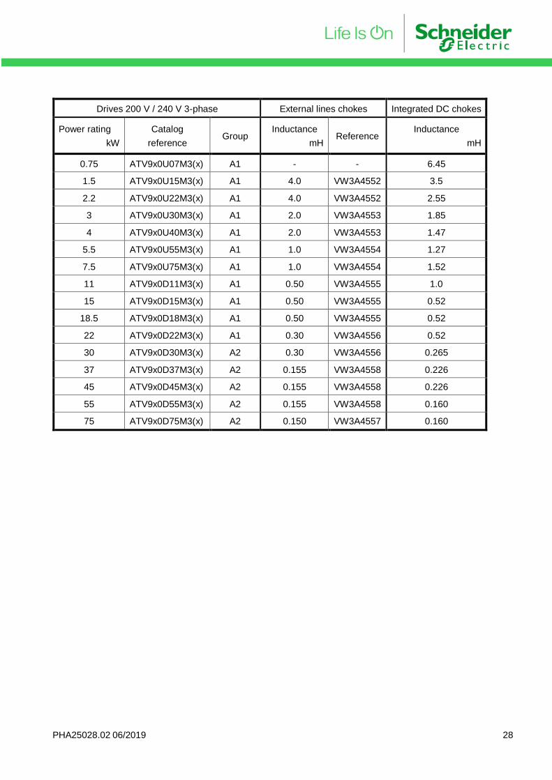
Line chokes Additional line chokes are required in some configuration (see section “Drives fed by DC terminals”).
Drives 400 V / 480 V External lines chokes Integrated DC chokes
Power rating
kW
Catalog
reference Group
Inductance
mH Reference
Inductance
mH
0.75 ATV9x0U07N4(x) A1 - - 21.6
1.5 ATV9x0U15N4(x) A1 10.0 VW3A4551 11.5
2.2 ATV9x0U22N4(x) A1 4.0 VW3A4552 8.10
3 ATV9x0U30N4(x) A1 4.0 VW3A4552 5.80
4 ATV9x0U40N4(x) A1 4.0 VW3A4552 4.55
5.5 ATV9x0U55N4(x) A1 2.0 VW3A4553 3.40
7.5 ATV9x0U75N4(x) A1 2.0 VW3A4553 2.90
11 ATV9x0D11N4(x) A1 1.0 VW3A4554 2.25
15 ATV9x0D15N4(x) A1 1.0 VW3A4554 1.52
18.5 ATV9x0D18N4(x) A1 0.50 VW3A4555 1.18
22 ATV9x0D22N4(x) A1 0.50 VW3A4555 1.00
30 ATV9x0D30N4(x) A2 0.50 VW3A4555 0.760
37 ATV9x0D37N4(x) A2 0.30 VW3A4556 0.585
45 ATV9x0D45N4(x) A2 0.30 VW3A4556 0.490
55 ATV9x0D55N4(x) A2 0.30 VW3A4556 0.365
75 ATV9x0D75N4(x) A2 0.30 VW3A4556 0.310
90 ATV9x0D90N4(x) A2 0.155 VW3A4558 0.226
110 ATV9x0C11N4(x) A2 0.120 VW3A4559 0.160
132 ATV9x0C13N4(x) A2 0.098 VW3A4560 0.160
160 ATV9x0C16N4(x) A2 0.066 VW3A4561 0.160
220 ATV9x0C22N4(x) A2 0.049 VW3A4562 0.105
250 ATV9x0C25N4(x) A2 0.049 VW3A4562 0.095
315 ATV9x0C31N4(x) A2 0.038 VW3A4564 0.069
PHA25028.02 06/2019 28
Drives 200 V / 240 V 3-phase External lines chokes Integrated DC chokes
Power rating
kW
Catalog
reference Group
Inductance
mH Reference
Inductance
mH
0.75 ATV9x0U07M3(x) A1 - - 6.45
1.5 ATV9x0U15M3(x) A1 4.0 VW3A4552 3.5
2.2 ATV9x0U22M3(x) A1 4.0 VW3A4552 2.55
3 ATV9x0U30M3(x) A1 2.0 VW3A4553 1.85
4 ATV9x0U40M3(x) A1 2.0 VW3A4553 1.47
5.5 ATV9x0U55M3(x) A1 1.0 VW3A4554 1.27
7.5 ATV9x0U75M3(x) A1 1.0 VW3A4554 1.52
11 ATV9x0D11M3(x) A1 0.50 VW3A4555 1.0
15 ATV9x0D15M3(x) A1 0.50 VW3A4555 0.52
18.5 ATV9x0D18M3(x) A1 0.50 VW3A4555 0.52
22 ATV9x0D22M3(x) A1 0.30 VW3A4556 0.52
30 ATV9x0D30M3(x) A2 0.30 VW3A4556 0.265
37 ATV9x0D37M3(x) A2 0.155 VW3A4558 0.226
45 ATV9x0D45M3(x) A2 0.155 VW3A4558 0.226
55 ATV9x0D55M3(x) A2 0.155 VW3A4558 0.160
75 ATV9x0D75M3(x) A2 0.150 VW3A4557 0.160
PHA25028.02 06/2019 29
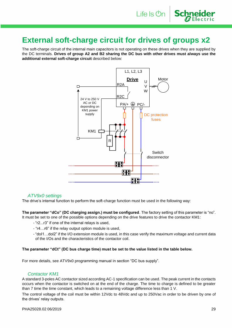
External soft-charge circuit for drives of groups x2 The soft-charge circuit of the internal main capacitors is not operating on these drives when they are supplied by
the DC terminals. Drives of group A2 and B2 sharing the DC bus with other drives must always use the
additional external soft-charge circuit described below:
ATV9x0 settings The drive’s internal function to perform the soft-charge function must be used in the following way:
The parameter “dCo” (DC charging assign.) must be configured. The factory setting of this parameter is “no”.
It must be set to one of the possible options depending on the drive features to drive the contactor KM1:
- “r2...r3” if one of the internal relays is used,
- “r4…r6” if the relay output option module is used,
- “doI1…doI2” if the I/O extension module is used, in this case verify the maximum voltage and current data
of the I/Os and the characteristics of the contactor coil.
The parameter “dCt” (DC bus charge time) must be set to the value listed in the table below.
For more details, see ATV9x0 programming manual in section “DC bus supply”.
Contactor KM1 A standard 3-poles AC contactor sized according AC-1 specification can be used. The peak current in the contacts
occurs when the contactor is switched on at the end of the charge. The time to charge is defined to be greater
than 7 time the time constant, which leads to a remaining voltage difference less than 1 V.
The control voltage of the coil must be within 12Vdc to 48Vdc and up to 250Vac in order to be driven by one of
the drives’ relay outputs.
PA/+ PC/-
L1, L2, L3
U
V
W
Drive Motor
R2A
R2C
KM1
R
24 V to 250 V
AC or DC
depending on
KM1 power
supply DC protection
fuses
Switch
disconnector
PHA25028.02 06/2019 30
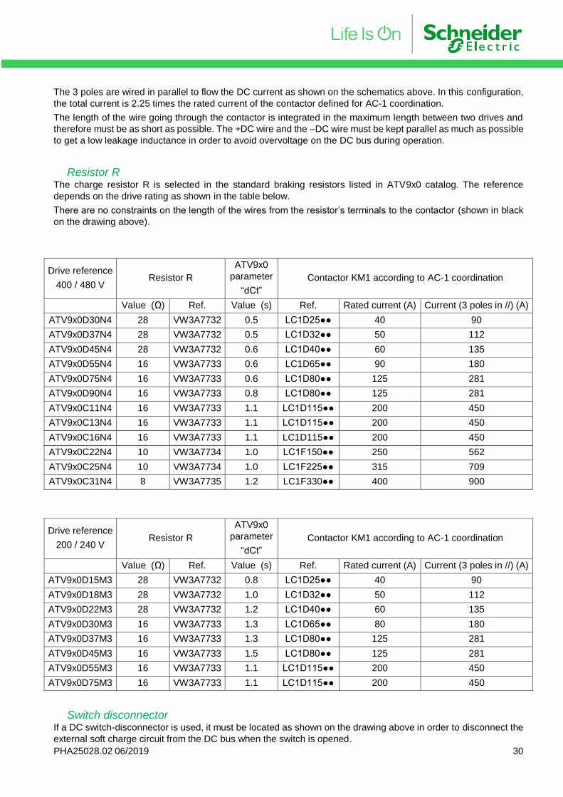
The 3 poles are wired in parallel to flow the DC current as shown on the schematics above. In this configuration,
the total current is 2.25 times the rated current of the contactor defined for AC-1 coordination.
The length of the wire going through the contactor is integrated in the maximum length between two drives and
therefore must be as short as possible. The +DC wire and the –DC wire must be kept parallel as much as possible
to get a low leakage inductance in order to avoid overvoltage on the DC bus during operation.
Resistor R The charge resistor R is selected in the standard braking resistors listed in ATV9x0 catalog. The reference
depends on the drive rating as shown in the table below.
There are no constraints on the length of the wires from the resistor’s terminals to the contactor (shown in black
on the drawing above).
Drive reference
400 / 480 V Resistor R
ATV9x0
parameter
“dCt”
Contactor KM1 according to AC-1 coordination
Value (Ω) Ref. Value (s) Ref. Rated current (A) Current (3 poles in //) (A)
ATV9x0D30N4 28 VW3A7732 0.5 LC1D25 40 90
ATV9x0D37N4 28 VW3A7732 0.5 LC1D32 50 112
ATV9x0D45N4 28 VW3A7732 0.6 LC1D40 60 135
ATV9x0D55N4 16 VW3A7733 0.6 LC1D65 90 180
ATV9x0D75N4 16 VW3A7733 0.6 LC1D80 125 281
ATV9x0D90N4 16 VW3A7733 0.8 LC1D80 125 281
ATV9x0C11N4 16 VW3A7733 1.1 LC1D115 200 450
ATV9x0C13N4 16 VW3A7733 1.1 LC1D115 200 450
ATV9x0C16N4 16 VW3A7733 1.1 LC1D115 200 450
ATV9x0C22N4 10 VW3A7734 1.0 LC1F150 250 562
ATV9x0C25N4 10 VW3A7734 1.0 LC1F225 315 709
ATV9x0C31N4 8 VW3A7735 1.2 LC1F330 400 900
Drive reference
200 / 240 V Resistor R
ATV9x0
parameter
“dCt”
Contactor KM1 according to AC-1 coordination
Value (Ω) Ref. Value (s) Ref. Rated current (A) Current (3 poles in //) (A)
ATV9x0D15M3 28 VW3A7732 0.8 LC1D25 40 90
ATV9x0D18M3 28 VW3A7732 1.0 LC1D32 50 112
ATV9x0D22M3 28 VW3A7732 1.2 LC1D40 60 135
ATV9x0D30M3 16 VW3A7733 1.3 LC1D65 80 180
ATV9x0D37M3 16 VW3A7733 1.3 LC1D80 125 281
ATV9x0D45M3 16 VW3A7733 1.5 LC1D80 125 281
ATV9x0D55M3 16 VW3A7733 1.1 LC1D115 200 450
ATV9x0D75M3 16 VW3A7733 1.1 LC1D115 200 450
Switch disconnector If a DC switch-disconnector is used, it must be located as shown on the drawing above in order to disconnect the
external soft charge circuit from the DC bus when the switch is opened.
PHA25028.02 06/2019 31
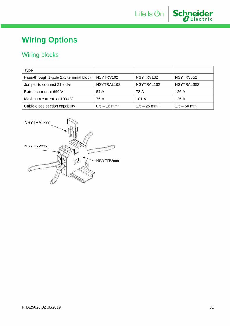
Wiring Options
Wiring blocks
Type
Pass-through 1-pole 1x1 terminal block NSYTRV102 NSYTRV162 NSYTRV352
Jumper to connect 2 blocks NSYTRAL102 NSYTRAL162 NSYTRAL352
Rated current at 690 V 54 A 73 A 126 A
Maximum current at 1000 V 76 A 101 A 125 A
Cable cross section capability 0.5 – 16 mm² 1.5 – 25 mm² 1.5 – 50 mm²
NSYTRVxxx
NSYTRVxxx
NSYTRALxxx

ATV900_DC_Bus_Sharing_Technical_Note_PHA25028_01
06/2019


![BUS BUS BUS BUS BUS BUS - Greater Anglia...London Liverpool Street to Hertford East, Stansted Airport and Cambridge Saturday 3rd December 2016 BUS BUS BUS BUS BUS BUS]]]] ]]]] ]]]]](https://img.pdfslide.net/doc/110x75/5e6fa285aaf29f59f73bda17/bus-bus-bus-bus-bus-bus-greater-anglia-london-liverpool-street-to-hertford.jpg)