Embed Size (px)
Citation preview
Operating Instructions
AUDIO/VIDEOMULTI-CHANNEL RECEIVER
VSX-908RDSVSX-908RDS-G
2
RISK OF ELECTRIC SHOCKDO NOT OPEN
CAUTIONIMPORTANT 1
CAUTION:TO PREVENT THE RISK OF ELECTRIC SHOCK, DONOT REMOVE COVER (OR BACK). NO USER-SERVICEABLE PARTS INSIDE. REFER SERVICING TOQUALIFIED SERVICE PERSONNEL.
The exclamation point within an equilateral triangle isintended to alert the user to the presence of importantoperating and maintenance (servicing) instructions inthe literature accompanying the appliance.
The lightning flash with arrowhead symbol, within anequilateral triangle, is intended to alert the user to thepresence of uninsulated "dangerous voltage" within theproduct's enclosure that may be of sufficient magnitudeto constitute a risk of electric shock to persons.
IMPORTANT 2 Do not connect either wire to the earth terminal of athree - pin plug.
NOTEAfter replacing or changing a fuse, the fuse cover in theplug must be replaced with a fuse cover which corre-sponds to the colour of the insert in the base of the plugor the word that is embossed on the base of the plug, andthe appliance must not be used without a fuse cover. Iflost replacement fuse covers can be obtained from:your dealer.Only 5 A fuses approved by B.S.I. or A.S.T.A. to B.S.1362 should be used.
The cut-off plug should be disposed of and must not beinserted into any 13 amp socket as this can result in electricshock. The plug or adaptor or the distribution panel shouldbe provided with 5 amp fuse. As the colours of the wires inthe mains lead of this appliance may not correspond withcoloured markings identifying the terminals in your plug,proceed as follows :The wire which is coloured blue must be connected to theterminal which is marked with the letter N or coloured black.The wire which is coloured brown must be connectedto the terminal which is marked with the letter L or colouredred.
FOR USE IN THE UNITED
KINGDOMThe wires in this mains lead are coloured in
accordance with the following code :
Blue : Neutral
Brown : Live
If the plug provided is unsuitable for your socketoutlets, the plug must be cut off and a suitable plugfitted.
Thank you for buying this Pioneer product.Please read through these operating instructionsso you will know how to operate your model prop-erly. After you have finished reading the instruc-tions, put them away in a safe place for future ref-erence.In some countries or regions, the shape of thepower plug and power outlet may sometimes dif-fer from that shown in the explanatory drawings.However, the method of connecting and operat-ing the unit is the same.
Power cord CAUTION!
Handle the power cord by the plug. Do not pullout the plug by tugging the cord and nevertouch the power cord when your hands arewet as this could cause a short circuit orelectric shock. Do not place the unit, a piece offurniture, etc., on the power cord, or pinch thecord. Never make a knot in the cord or tie itwith other cords. The power cords should berouted such that they are not likely to bestepped on. A damaged power cord can causea fire or give you an electrical shock. Check thepower cord once in a while. When you find itdamaged, ask your nearest PIONEER autho-rized service center or your dealer for a re-placement.
WARNING: TO PREVENT FIRE OR SHOCK HAZARD,DO NOT EXPOSE THIS APPLIANCE TO RAIN ORMOISTURE.
THE POWER SWITCH IS SECONDARY CONNECTEDAND THEREFORE DOES NOT SEPARATE THE UNITFROM MAINS POWER IN STANDBY POSITION.
This product complies with the Low Voltage Directive(73/23/EEC), EMC Directives (89/336/EEC, 92/31/EEC)and CE Marking Directive (93/68/EEC).
[For European model]If the socket outlets on the associated equipmentare not suitable for the plug supplied with theproduct the plug must be removed andappropriate one fitted.The cut-off plug must be disposed of as anelectrical shock hazard could exist if connected toa socket outlet.
Maintenance of External Surfaces
• Use a polishing cloth or dry cloth to wipe off dust and dirt.• When the surfaces are dirty, wipe with a soft cloth dipped in some neutral cleanser diluted five or six times
with water, and wrung out well, and then wipe again with a dry cloth. Do not use furniture wax or cleansers.• Never use thinners, benzine, insecticide sprays or other chemicals on or near this unit, since these will corrode
the surfaces.
3
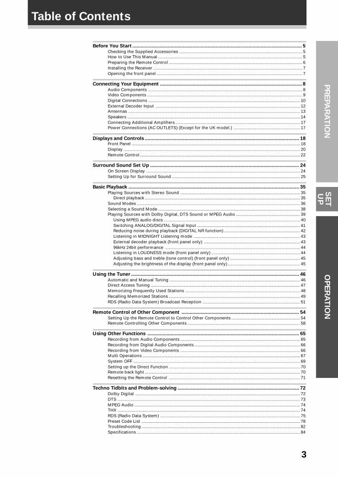
Table of ContentsP
RE
PA
RA
TIO
NO
PE
RA
TIO
NS
ET
UP
Before You Start ............................................................................................................................ 5Checking the Supplied Accessories ........................................................................................................ 5How to Use This Manual .......................................................................................................................... 5Preparing the Remote Control .................................................................................................................6Installing the Receiver ..............................................................................................................................7Opening the front panel ........................................................................................................................... 7
Connecting Your Equipment ........................................................................................................ 8Audio Components .................................................................................................................................. 8Video Components ...................................................................................................................................9Digital Connections ................................................................................................................................ 10External Decoder Input .......................................................................................................................... 12Antennas ................................................................................................................................................. 13Speakers .................................................................................................................................................. 14Connecting Additional Amplifiers ......................................................................................................... 17Power Connections (AC OUTLETS) (Except for the UK model.) ........................................................ 17
Displays and Controls ................................................................................................................. 18Front Panel .............................................................................................................................................. 18Display ..................................................................................................................................................... 20Remote Control ....................................................................................................................................... 22
Surround Sound Set Up ............................................................................................................. 24On Screen Display .................................................................................................................................. 24Setting Up for Surround Sound ............................................................................................................ 25
Basic Playback ............................................................................................................................. 35Playing Sources with Stereo Sound ..................................................................................................... 35
Direct playback ................................................................................................................................... 35Sound Modes .......................................................................................................................................... 36Selecting a Sound Mode ........................................................................................................................ 38Playing Sources with Dolby Digital, DTS Sound or MPEG Audio ...................................................... 39
Using MPEG audio discs ................................................................................................................... 40Switching ANALOG/DIGITAL Signal Input ....................................................................................... 41Reducing noise during playback (DIGITAL NR function) ................................................................ 42Listening in MIDNIGHT Listening mode .......................................................................................... 43External decoder playback (front panel only) ................................................................................. 4396kHz 24bit performance .................................................................................................................. 44Listening in LOUDNESS mode (front panel only) ........................................................................... 44Adjusting bass and treble (tone control) (front panel only) ........................................................... 45Adjusting the brightness of the display (front panel only) ............................................................. 45
Using the Tuner ........................................................................................................................... 46Automatic and Manual Tuning .............................................................................................................. 46Direct Access Tuning .............................................................................................................................. 47Memorizing Frequently Used Stations ................................................................................................. 48Recalling Memorized Stations ............................................................................................................... 49RDS (Radio Data System) Broadcast Reception .................................................................................. 51
Remote Control of Other Component ...................................................................................... 54Setting Up the Remote Control to Control Other Components .......................................................... 54Remote Controlling Other Components ............................................................................................... 58
Using Other Functions ............................................................................................................... 65Recording from Audio Components ..................................................................................................... 65Recording from Digital Audio Components ......................................................................................... 66Recording from Video Components ..................................................................................................... 66Multi Operations ..................................................................................................................................... 67System OFF ............................................................................................................................................. 69Setting up the Direct Function ............................................................................................................... 70Remote back light ................................................................................................................................... 70Resetting the Remote Control ............................................................................................................... 71
Techno Tidbits and Problem-solving ......................................................................................... 72Dolby Digital ........................................................................................................................................... 72DTS .......................................................................................................................................................... 73MPEG Audio ............................................................................................................................................ 74THX .......................................................................................................................................................... 74RDS (Radio Data System) ...................................................................................................................... 75Preset Code List ...................................................................................................................................... 78Troubleshooting ...................................................................................................................................... 82Specifications .......................................................................................................................................... 84
4
Features
MPEG (Moving Picture ExpertsGroup) decoder equipped
DVD and other media recorded in MPEG audio canalso be played back.
The MPEG logo is a registered trademark ofRoyal Philips Electronics.
Automatic Decoding of DTS(Digital Theater Systems)
R
This is the latest and most widely used digital theatersystem for cinemas throughout the world. Thedecoder has been incorporated into this receiver andis able to achieve high sound quality as well asproduce dynamic surround sound effects.
“DTS” and “DTS Digital Surround” aretrademarks of Digital Theater Systems, Inc.Manufactured under licence from Digital TheaterSystems, Inc.
Automatic Decoding of DolbyDigital and Dolby Pro Logic
No need to worry about program formats. Whenplaying Dolby Digital or Dolby Surround software inthe 2 (Dolby) Surround mode, decoding switchesautomatically according to the input signal.
Manufactured under license from DolbyLaboratories. “Dolby”, “AC-3”, “Pro Logic”,and double-D symbol are trademarks of DolbyLaboratories. Confidential Unpublished Works.© 1992 - 1997 Dolby Laboratories. All rightsreserved.
Direct Energy MOS Amplifier
This receiver incorporates 5 independent 110 wattpower amplifiers, built with high-performance Hexpower MOS FET output transistors. Thisconstruction provides improved linearity and accuratereproduction of each channel for true high fidelityreproduction from even the most demanding DolbyDigital and DTS program sources.
RDS (Radio-Data System)
With the RDS system, FM station can sendadditional signals with their regular program signals.For example, the stations send their station names,and information about the type of programs theybroadcast, such as news, sports or music. This unitreceives three types of RDS signals: RT, PS, andPTY.
True Home Cinema with THX®
Certification
The HOME THX CINEMA surround mode employsspecial processing to allow you to enjoy moviesoundtracks with the same level of power andrealism you experience in well designed movietheaters. You can enjoy this effect with both DolbyDigital, Dolby Surround and DTS sources.
Manufactured under license from Lucasfilm Ltd.Lucasfilm and THX are trademarks of LucasfilmLtd.
Advanced Theater Modes
This mode enhances the sound of either film ormusic so a more dramatic effect can be achieved.The four modes are each designed to accentuatespecific sound qualities, giving the listener a widerange of possibilities.
DSP Surround Modes
DSP (Digital Signal Processing) surround mode givesyou the capability of transforming your living roominto six different sonic environments when listeningto music or movies.
Midnight Listening Mode
Midnight Listening mode allows you to obtainexcellent surround sound effects even whenlistening at low volumes, something that waspreviously impossible.
Digital Noise Reduction
Digital Noise Reduction is the latest technology forfiltering out unwanted noise. It produces clear,resonant tones.
Remote Control of OtherComponents
The supplied remote control can be used to operate avariety of other components simply by recalling theappropriate preset codes or by using the learningfunction to teach the remote control new commands.In addition, the multi-operation functions allow you toperform more than one operation at a time.
The Energy-saving Design
This unit is designed to use minimal electricity whenpower is switched OFF (in the Standby mode).Regarding the value of the power consumption in thestandby mode, refer to “Specifications” on 84.
5
PR
EPA
RA
TIO
N
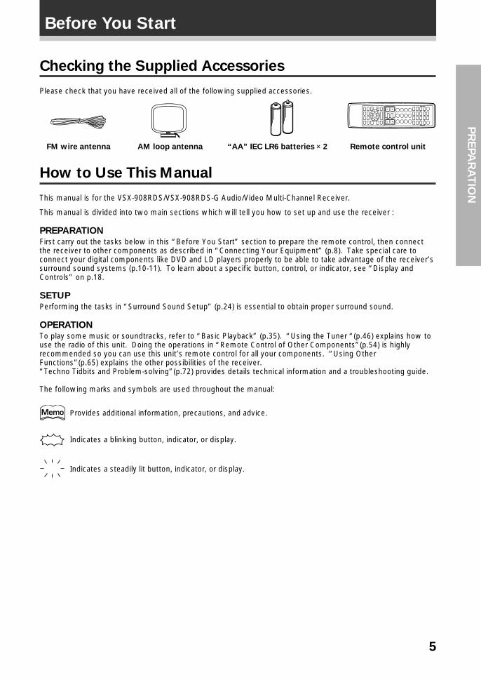
Checking the Supplied Accessories
Please check that you have received all of the following supplied accessories.
FM wire antenna
How to Use This Manual
This manual is for the VSX-908RDS/VSX-908RDS-G Audio/Video Multi-Channel Receiver.
This manual is divided into two main sections which will tell you how to set up and use the receiver :
PREPARATION
First carry out the tasks below in this “Before You Start” section to prepare the remote control, then connectthe receiver to other components as described in “Connecting Your Equipment” (p.8). Take special care toconnect your digital components like DVD and LD players properly to be able to take advantage of the receiver’ssurround sound systems (p.10-11). To learn about a specific button, control, or indicator, see “Display andControls” on p.18.
SETUP
Performing the tasks in “Surround Sound Setup” (p.24) is essential to obtain proper surround sound.
OPERATION
To play some music or soundtracks, refer to “Basic Playback” (p.35). “Using the Tuner “(p.46) explains how touse the radio of this unit. Doing the operations in “Remote Control of Other Components”(p.54) is highlyrecommended so you can use this unit’s remote control for all your components. “Using OtherFunctions”(p.65) explains the other possibilities of the receiver.“Techno Tidbits and Problem-solving”(p.72) provides details technical information and a troubleshooting guide.
The following marks and symbols are used throughout the manual:
Provides additional information, precautions, and advice.
Indicates a blinking button, indicator, or display.
Indicates a steadily lit button, indicator, or display.
AM loop antenna “AA” IEC LR6 batteries × 2 Remote control unit
Before You Start
6
1 2 3
Preparing the Remote Control
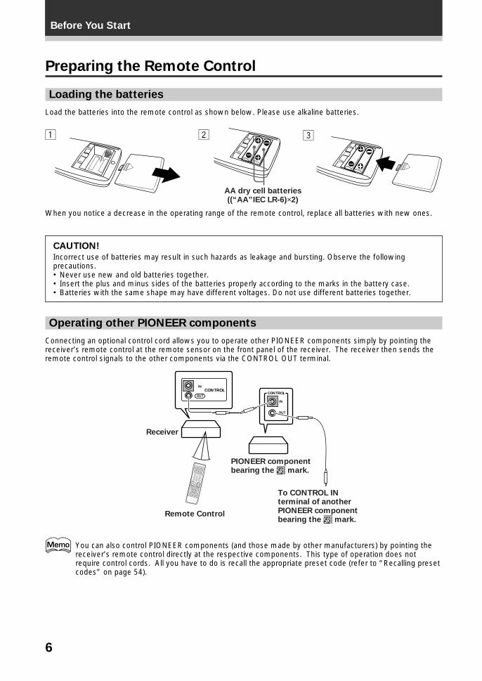
Loading the batteries
Load the batteries into the remote control as shown below. Please use alkaline batteries.
When you notice a decrease in the operating range of the remote control, replace all batteries with new ones.
CAUTION!
Incorrect use of batteries may result in such hazards as leakage and bursting. Observe the followingprecautions.• Never use new and old batteries together.• Insert the plus and minus sides of the batteries properly according to the marks in the battery case.• Batteries with the same shape may have different voltages. Do not use different batteries together.
Operating other PIONEER components
Connecting an optional control cord allows you to operate other PIONEER components simply by pointing thereceiver’s remote control at the remote sensor on the front panel of the receiver. The receiver then sends theremote control signals to the other components via the CONTROL OUT terminal.
AA dry cell batteries((“AA”IEC LR-6)×2)
OUT
INCONTROL
OUT
IN
CONTROL
PIONEER component bearing the Î mark.
Remote Control
To CONTROL IN terminal of another PIONEER component bearing the Î mark.
Receiver
You can also control PIONEER components (and those made by other manufacturers) by pointing thereceiver’s remote control directly at the respective components. This type of operation does notrequire control cords. All you have to do is recall the appropriate preset code (refer to “Recalling presetcodes” on page 54).
Before You Start
7
PR
EPA
RA
TIO
N
Before You Start
Installing the Receiver
Ventilation
Opening the front panel
To open the front panel, push gently on the lower third of the panel with your finger.
• When installing this unit, make sure to leave space around the unit for ventilation to improve heat radiation (atleast 60 cm at the top, 10 cm at the rear, and 30 cm at each side). If not enough space is provided betweenthe unit and walls or other equipment, heat will build up inside, interfering with performance or causingmalfunctions.
• Do not place on a thick carpet, bed, sofa or fabric having a thick pile. Do not cover with fabric or othercovering.Anything that blocks ventilation will cause the internal temperature to rise, which may lead to breakdown orfire hazard.
Operating range of the remote control unit
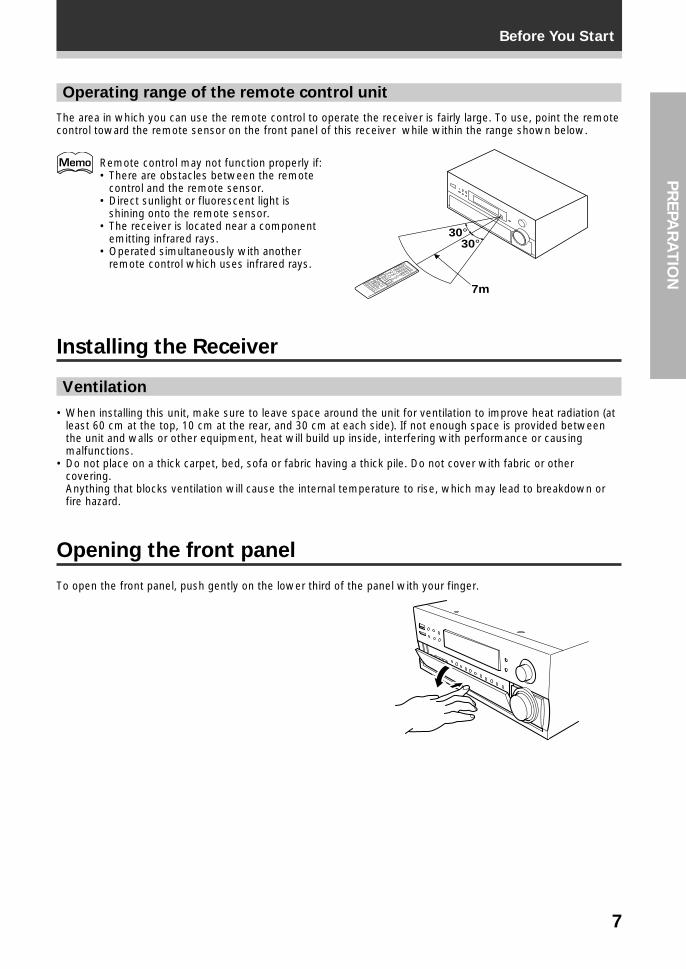
The area in which you can use the remote control to operate the receiver is fairly large. To use, point the remotecontrol toward the remote sensor on the front panel of this receiver while within the range shown below.
Remote control may not function properly if:• There are obstacles between the remote
control and the remote sensor.• Direct sunlight or fluorescent light is
shining onto the remote sensor.• The receiver is located near a component
emitting infrared rays.• Operated simultaneously with another
remote control which uses infrared rays.
30°30°
7m
8
UNSWITCHED100W MAX
DIGITAL
FMANTENNA
IN
OUT
OUT
IN
IN
IN
VCR2
CONTROL
VCR1
PHONO
TV/SATIN
TOMONITOR
TV
DVD/LDIN
VIDEOOUT
FRONTSPEAKERS
SEE INSTRUCTION MANUAL SE REPORTER AU MODE D’EMPLOI
SURROUNDSPEAKERS
FRONTSPEAKERS
SWITCHED TOTAL 100W MAX
CENTERSPEAKER
MD/TAPE1/CD-R
FM UNBAL75Ω
TAPE2MONITOR
CD
AM LOOPANTENNA
1
PREOUT
2 3 4PCM/ /DTS/MPEG IN
RF IN
PCM/ /DTS/MPEG OUT
R L VIDEO
FR FL C SR SL R L
INS
INS
R L
INS
OUTS
OUTS
OUTS
INS
SR
SL
SL
SR
FR
FL
FL
FRC
C
SW
SW
IN
PLAY
PLAY
PLAY
REC
REC
OUT
EXTERNALDECODER
IN
A B
AC OUTLETS
REC PLAY
L
R
REC PLAY
L
R
L
R
OUTPUT
CD playerTurntable
MD recorder or Cassette deck
Cassette deck(with REC monitor)
If your turntable has a ground wire, connect it to the (signal ground) terminal.
The illustration is not applicable to the UK model.
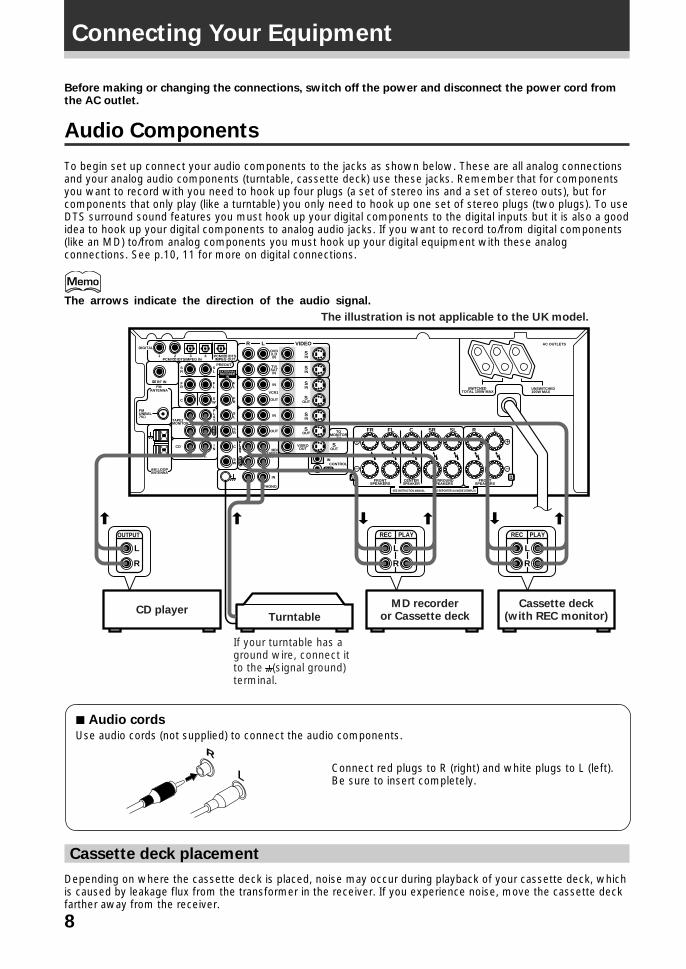
Before making or changing the connections, switch off the power and disconnect the power cord fromthe AC outlet.
Audio Components
To begin set up connect your audio components to the jacks as shown below. These are all analog connectionsand your analog audio components (turntable, cassette deck) use these jacks. Remember that for componentsyou want to record with you need to hook up four plugs (a set of stereo ins and a set of stereo outs), but forcomponents that only play (like a turntable) you only need to hook up one set of stereo plugs (two plugs). To useDTS surround sound features you must hook up your digital components to the digital inputs but it is also a goodidea to hook up your digital components to analog audio jacks. If you want to record to/from digital components(like an MD) to/from analog components you must hook up your digital equipment with these analogconnections. See p.10, 11 for more on digital connections.
The arrows indicate the direction of the audio signal.
7 Audio cords
Use audio cords (not supplied) to connect the audio components.
Cassette deck placement
Depending on where the cassette deck is placed, noise may occur during playback of your cassette deck, whichis caused by leakage flux from the transformer in the receiver. If you experience noise, move the cassette deckfarther away from the receiver.
Connect red plugs to R (right) and white plugs to L (left).Be sure to insert completely.L
R
Connecting Your Equipment
9
Connecting Your EquipmentP
RE
PA
RA
TIO
N
UNSWITCHED100W MAX
DIGITAL
FMANTENNA
IN
OUT
OUT
IN
IN
IN
VCR2
CONTROL
VCR1
PHONO
TV/SATIN
TOMONITOR
TV
DVD/LDIN
VIDEOOUT
FRONTSPEAKERS
SEE INSTRUCTION MANUAL SE REPORTER AU MODE D’EMPLOI
SURROUNDSPEAKERS
FRONTSPEAKERS
SWITCHED TOTAL 100W MAX
CENTERSPEAKER
MD/TAPE1/CD-R
FM UNBAL75Ω
TAPE2MONITOR
CD
AM LOOPANTENNA
1
PREOUT
2 3 4PCM/ /DTS/MPEG IN
RF IN
PCM/ /DTS/MPEG OUT
R L VIDEO
FR FL C SR SL R L
INS
INS
R L
INS
OUTS
OUTS
OUTS
INS
SR
SL
SL
SR
FR
FL
FL
FRC
C
SW
SW
IN
PLAY
PLAY
PLAY
REC
REC
OUT
EXTERNALDECODER
IN
A B
AC OUTLETS
OUTPUT INPUT
VIDEO
L
R
VIDEO
L
R
OUTPUT INPUT
VIDEO
L
R
VIDEO
L
R
OUTPUT
VIDEO
L
R
OUTPUT
VIDEO
L
R
INPUT
VIDEOPHONES
S-VIDEO
5-CHANNEL EQUAL POWER OUTPUT
VIDEO
EXTERNALDECODER IN DIRECT
SPEAKERS
L AUDIO RVIDEO INPUT
VIDEO
LV R
VIDEO INPUT
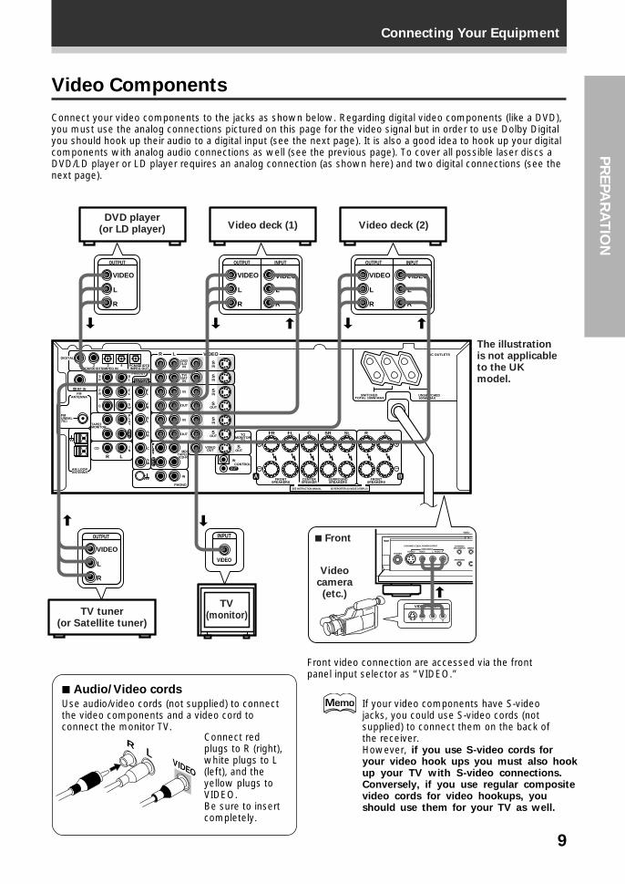
The illustration is not applicable to the UK model.
DVD player(or LD player) Video deck (1) Video deck (2)
TV tuner(or Satellite tuner)
TV (monitor)
7 Front
Video camera
(etc.)
Video Components
Connect your video components to the jacks as shown below. Regarding digital video components (like a DVD),you must use the analog connections pictured on this page for the video signal but in order to use Dolby Digitalyou should hook up their audio to a digital input (see the next page). It is also a good idea to hook up your digitalcomponents with analog audio connections as well (see the previous page). To cover all possible laser discs aDVD/LD player or LD player requires an analog connection (as shown here) and two digital connections (see thenext page).
Front video connection are accessed via the frontpanel input selector as “VIDEO.”
7 Audio/Video cords
Use audio/video cords (not supplied) to connectthe video components and a video cord toconnect the monitor TV.
Connect redplugs to R (right),white plugs to L(left), and theyellow plugs toVIDEO.Be sure to insertcompletely.
If your video components have S-videojacks, you could use S-video cords (notsupplied) to connect them on the back ofthe receiver.However, if you use S-video cords foryour video hook ups you must also hookup your TV with S-video connections.Conversely, if you use regular compositevideo cords for video hookups, youshould use them for your TV as well.
LR
VIDEO
10
Connecting Your Equipment
UNSWITCHED100W MAX
DIGITAL
FMANTENNA
IN
OUT
OUT
IN
IN
IN
VCR2
CONTROL
VCR1
PHONO
TV/SATIN
TOMONITOR
TV
DVD/LDIN
VIDEOOUT
FRONTSPEAKERS
SEE INSTRUCTION MANUAL SE REPORTER AU MODE D’EMPLOI
SURROUNDSPEAKERS
FRONTSPEAKERS
SWITCHED TOTAL 100W MAX
CENTERSPEAKER
MD/TAPE1/CD-R
FM UNBAL75Ω
TAPE2MONITOR
CD
AM LOOPANTENNA
1
PREOUT
2 3 4PCM/ /DTS/MPEG IN
RF IN
PCM/ /DTS/MPEG OUT
R L VIDEO
FR FL C SR SL R L
INS
INS
R L
INS
OUTS
OUTS
OUTS
INS
SR
SL
SL
SR
FR
FL
FL
FRC
C
SW
SW
IN
PLAY
PLAY
PLAY
REC
REC
OUT
EXTERNALDECODER
IN
A B
AC OUTLETS
OUT
DIGITALOUT
DIGITAL DIGITALIN
DIGITALOUT
DIGITAL OUTOPT.
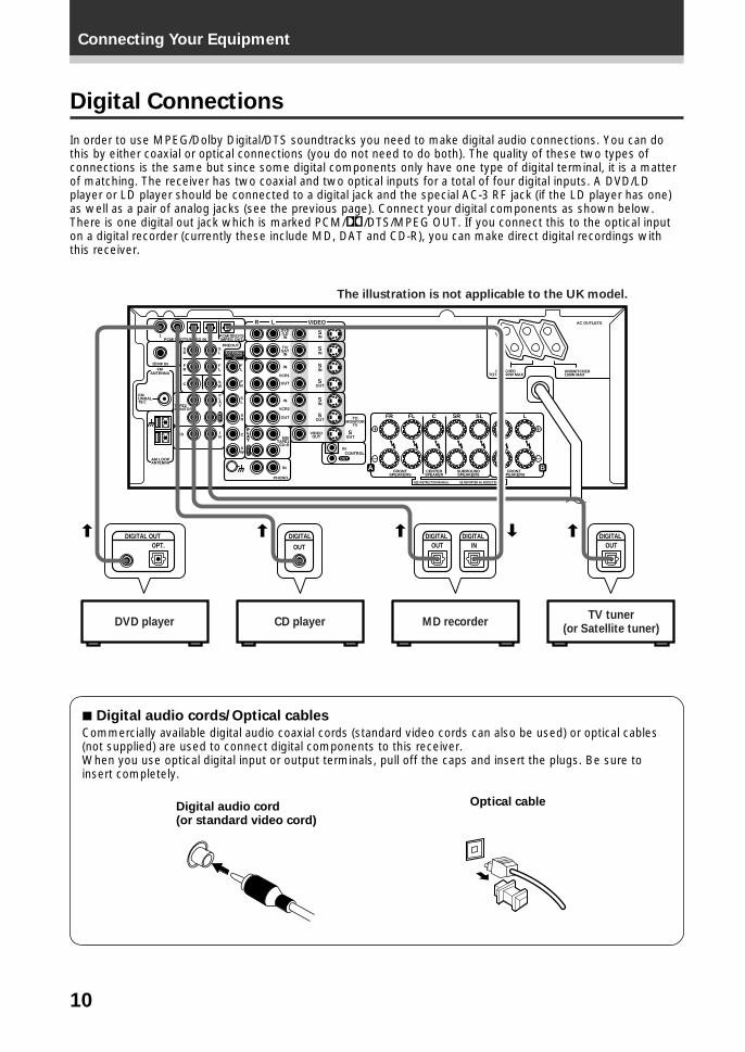
The illustration is not applicable to the UK model.
CD player MD recorderDVD playerTV tuner
(or Satellite tuner)
Digital Connections
In order to use MPEG/Dolby Digital/DTS soundtracks you need to make digital audio connections. You can dothis by either coaxial or optical connections (you do not need to do both). The quality of these two types ofconnections is the same but since some digital components only have one type of digital terminal, it is a matterof matching. The receiver has two coaxial and two optical inputs for a total of four digital inputs. A DVD/LDplayer or LD player should be connected to a digital jack and the special AC-3 RF jack (if the LD player has one)as well as a pair of analog jacks (see the previous page). Connect your digital components as shown below.There is one digital out jack which is marked PCM/2/DTS/MPEG OUT. If you connect this to the optical inputon a digital recorder (currently these include MD, DAT and CD-R), you can make direct digital recordings withthis receiver.
7 Digital audio cords/Optical cables
Commercially available digital audio coaxial cords (standard video cords can also be used) or optical cables(not supplied) are used to connect digital components to this receiver.When you use optical digital input or output terminals, pull off the caps and insert the plugs. Be sure toinsert completely.
Digital audio cord(or standard video cord)
Optical cable
11
Connecting Your EquipmentP
RE
PA
RA
TIO
N
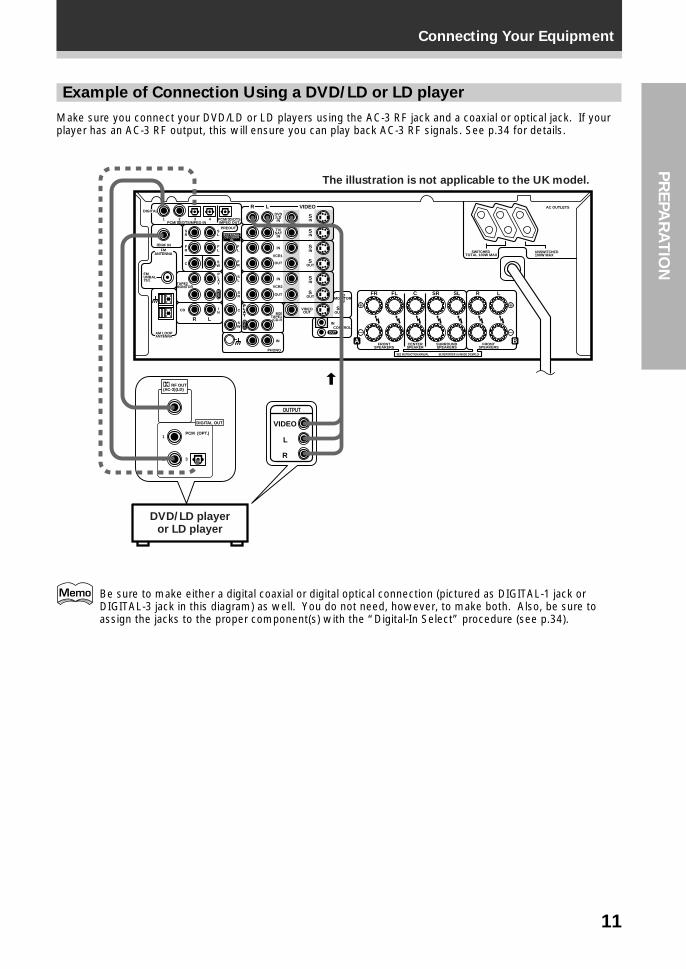
Example of Connection Using a DVD/LD or LD player
Make sure you connect your DVD/LD or LD players using the AC-3 RF jack and a coaxial or optical jack. If yourplayer has an AC-3 RF output, this will ensure you can play back AC-3 RF signals. See p.34 for details.
UNSWITCHED100W MAX
DIGITAL
FMANTENNA
IN
OUT
OUT
IN
IN
IN
VCR2
CONTROL
VCR1
PHONO
TV/SATIN
TOMONITOR
TV
DVD/LDIN
VIDEOOUT
FRONTSPEAKERS
SEE INSTRUCTION MANUAL SE REPORTER AU MODE D’EMPLOI
SURROUNDSPEAKERS
FRONTSPEAKERS
SWITCHED TOTAL 100W MAX
CENTERSPEAKER
MD/TAPE1/CD-R
FM UNBAL75Ω
TAPE2MONITOR
CD
AM LOOPANTENNA
1
PREOUT
2 3 4PCM/ /DTS/MPEG IN
RF IN
PCM/ /DTS/MPEG OUT
R L VIDEO
FR FL C SR SL R L
INS
INS
R L
INS
OUTS
OUTS
OUTS
INS
SR
SL
SL
SR
FR
FL
FL
FRC
C
SW
SW
IN
PLAY
PLAY
PLAY
REC
REC
OUT
EXTERNALDECODER
IN
A B
AC OUTLETS
RF OUT(AC-3)(LD)
DIGITAL OUT
1
2 3
PCM (OPT.)
DVD/LD playeror LD player
The illustration is not applicable to the UK model.
OUTPUT
VIDEO
L
R
Be sure to make either a digital coaxial or digital optical connection (pictured as DIGITAL-1 jack orDIGITAL-3 jack in this diagram) as well. You do not need, however, to make both. Also, be sure toassign the jacks to the proper component(s) with the “Digital-In Select” procedure (see p.34).
12
Connecting Your Equipment
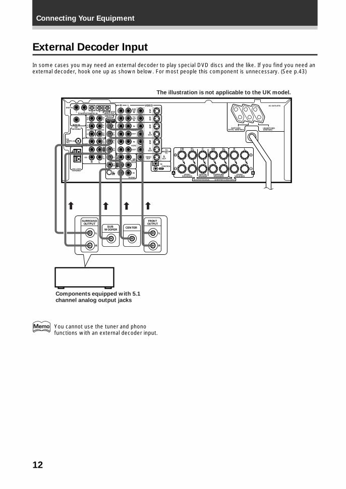
External Decoder Input
In some cases you may need an external decoder to play special DVD discs and the like. If you find you need anexternal decoder, hook one up as shown below. For most people this component is unnecessary. (See p.43)
UNSWITCHED100W MAX
DIGITAL
FMANTENNA
IN
OUT
OUT
IN
IN
IN
VCR2
CONTROL
VCR1
PHONO
TV/SATIN
TOMONITOR
TV
DVD/LDIN
VIDEOOUT
FRONTSPEAKERS
SEE INSTRUCTION MANUAL SE REPORTER AU MODE D’EMPLOI
SURROUNDSPEAKERS
FRONTSPEAKERS
SWITCHED TOTAL 100W MAX
CENTERSPEAKER
MD/TAPE1/CD-R
FM UNBAL75Ω
TAPE2MONITOR
CD
AM LOOPANTENNA
1
PREOUT
2 3 4PCM/ /DTS/MPEG IN
RF IN
PCM/ /DTS/MPEG OUT
R L VIDEO
FR FL C SR SL R L
INS
INS
R L
INS
OUTS
OUTS
OUTS
INS
SR
SL
SL
SR
FR
FL
FL
FRC
C
SW
SW
IN
PLAY
PLAY
PLAY
REC
REC
OUT
EXTERNALDECODER
IN
A B
AC OUTLETS
L
R
SURROUNDOUTPUT
L
R
FRONTOUTPUT
CENTERSUB WOOFER
» » » »
Components equipped with 5.1 channel analog output jacks
The illustration is not applicable to the UK model.
You cannot use the tuner and phonofunctions with an external decoder input.
13
Connecting Your EquipmentP
RE
PA
RA
TIO
N
FMANTENNA
FM UNBAL75Ω
AM LOOPANTENNA
Indoor antenna (Vinyl-coated wire)
ground
Outdoor antenna
5–6 m
7 AM loop antenna
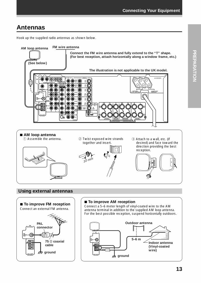
Antennas
Hook up the supplied radio antennas as shown below.
1 Assemble the antenna. 2 Twist exposed wire strandstogether and insert.
3 Attach to a wall, etc. (ifdesired) and face toward thedirection providing the bestreception.
Using external antennas
7 To improve FM reception
Connect an external FM antenna.
7 To improve AM receptionConnect a 5–6 meter length of vinyl-coated wire to the AMantenna terminal in addition to the supplied AM loop antenna.For the best possible reception, suspend horizontally outdoors.
UNSWITCHED100W MAX
DIGITAL
FMANTENNA
IN
OUT
OUT
IN
IN
IN
VCR2
CONTROL
VCR1
PHONO
TV/SATIN
TOMONITOR
TV
DVD/LDIN
VIDEOOUT
FRONTSPEAKERS
SEE INSTRUCTION MANUAL SE REPORTER AU MODE D’EMPLOI
SURROUNDSPEAKERS
FRONTSPEAKERS
SWITCHED TOTAL 100W MAX
CENTERSPEAKER
MD/TAPE1/CD-R
FM UNBAL75Ω
TAPE2MONITOR
CD
AM LOOPANTENNA
1
PREOUT
2 3 4PCM/ /DTS/MPEG IN
RF IN
PCM/ /DTS/MPEG OUT
R L VIDEO
FR FL C SR SL R L
INS
INS
R L
INS
OUTS
OUTS
OUTS
INS
SR
SL
SL
SR
FR
FL
FL
FRC
C
SW
SW
IN
PLAY
PLAY
PLAY
REC
REC
OUT
EXTERNALDECODER
IN
A B
AC OUTLETS
The illustration is not applicable to the UK model.
FM wire antennaAM loop antenna
(See below)
Connect the FM wire antenna and fully extend to the “T” shape.(For best reception, attach horizontally along a window frame, etc.)
10 mm
FMANTENNA
FM UNBAL75Ω
AM LOOPANTENNA
75 Ω coaxial cable
PALconnector
ground
14
Connecting Your Equipment
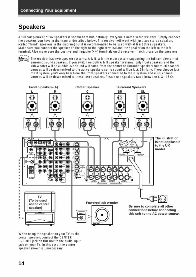
Speakers
A full complement of six speakers is shown here but, naturally, everyone’s home setup will vary. Simply connectthe speakers you have in the manner described below. The receiver will work with just two stereo speakers(called “front” speakers in the diagram) but it is recommended to be used with at least three speakers.Make sure you connect the speaker on the right to the right terminal and the speaker on the left to the leftterminal. Also make sure the positive and negative (+/–) terminals on the receiver match those on the speakers.
The receiver has two speaker systems, A & B. A is the main system supporting the full complement ofsurround sound speakers. If you switch on both A & B speaker systems, only front speakers and thesub-woofer will be audible. No sound will come from the center or surround speakers but multi channelsources will be down-mixed to the active speakers so no sound will be lost. Similarly, if you choose justthe B system you‘ll only hear from the front speakers connected to the B system and multi channelsources will be down-mixed to these two speakers. Please use speakers rated between 6 Ω - 16 Ω.
UNSWITCHED100W MAX
DIGITAL
FMANTENNA
IN
OUT
OUT
IN
IN
IN
VCR2
CONTROL
VCR1
PHONO
TV/SATIN
TOMONITOR
TV
DVD/LDIN
VIDEOOUT
FRONTSPEAKERS
SEE INSTRUCTION MANUAL SE REPORTER AU MODE D’EMPLOI
SURROUNDSPEAKERS
FRONTSPEAKERS
SWITCHED TOTAL 100W MAX
CENTERSPEAKER
MD/TAPE1/CD-R
FM UNBAL75Ω
TAPE2MONITOR
CD
AM LOOPANTENNA
1
PREOUT
2 3 4PCM/ /DTS/MPEG IN
RF IN
PCM/ /DTS/MPEG OUT
R L VIDEO
FR FL C SR SL R L
INS
INS
R L
INS
OUTS
OUTS
OUTS
INS
SR
SL
SL
SR
FR
FL
FL
FRC
C
SW
SW
IN
PLAY
PLAY
PLAY
REC
REC
OUT
EXTERNALDECODER
IN
A B
AC OUTLETS
INPUT
The illustration is not applicable to the UK model.
Be sure to complete all other connections before connecting this unit to the AC power source.
Front Speakers (A)
L C SR SLR
Center Speaker Surround Speakers
Powered sub woofer
TV(To be used as the center speaker)
When using the speaker on your TV as thecenter speaker, connect the CENTERPREOUT jack on this unit to the audio inputjack on your TV. In this case, the centerspeaker shown is unnecessary.

15
Connecting Your EquipmentP
RE
PA
RA
TIO
N
Before operating the receiver, be sure to press the main powerbutton on the front panel to turn the power ON (_).
First turn the receiver off (Standby mode), then press theSTANDBY/ON button while holding down theSPEAKERS button.
Choose the impedance setting by pressing the SPEAKERS button again.You can choose the 8 Ω-16 Ω setting or the 6 Ω-less than 8 Ω setting.
To check which impedance the amp is set to, hold down theSPEAKERS button for 2-3 seconds. You will get a display likethe one shown below telling you the speaker impedancesetting.
7 Speaker terminals
1 Twist exposed wirestrands together.
2 Loosen speaker terminaland insert exposed wire.
Speaker impedance
You can change the speaker impedance to suit the kind of speakers you have in your home system. Werecommend, however, using speakers with an impedance of 8 Ω-16 Ω (the default setting). If you are using 6 Ω−less than 8 Ω impedance speakers, you need to change the impedance setting.
(This display indicates an 6 Ω-less than8 Ω impedance setting)
(This display indicates an 8 Ω-16 Ωimpedance setting.)
or
(This display indicates an 6 Ω-lessthan 8 Ω impedance setting.)
10 mm
dB
SIGNALSELECTANALOG SP A
VOLUME
dB
SIGNALSELECTANALOG SP A
VOLUME
dB
SIGNALSELECTANALOG SP A
VOLUME
STANDBY/ON
—OFF _ON
DSPMODESTANDBY
AUDIO/VIDEO MULTI-CHANNEL RECEIVER
STEREO
PHONES S-VIDEO
5-CHANNEL EQUAL POWER OUTPUT
VIDEO
EXTERNALDECODER IN
TAPE 2MONITOR
DIRECT LOUDNESS MIDNIGHTDIGITAL
NR CLASS FM/
MEMCHARACTER/SEARCHINPUT ATTSPEAKERS – TREBLE +– BASS +
L AUDIO RVIDEO INPUT
THX CINEMA ADVANCED STANDARD
/DTS
MPEG
RF ATTSIGNALSELECT
SPEAKERSMain power button
STANDBY/ON
3 Tighten terminal.
16
Connecting Your Equipment
Surround Left
Surround Right
Listening Position
FrontLeft
FrontRightCenter
Sub Woofer
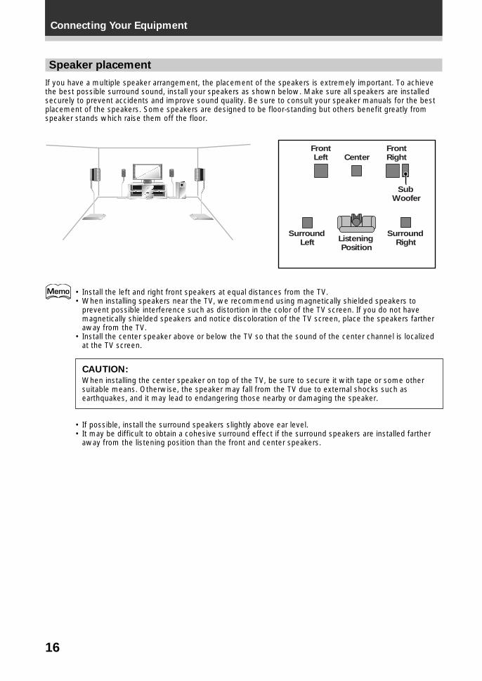
Speaker placement
If you have a multiple speaker arrangement, the placement of the speakers is extremely important. To achievethe best possible surround sound, install your speakers as shown below. Make sure all speakers are installedsecurely to prevent accidents and improve sound quality. Be sure to consult your speaker manuals for the bestplacement of the speakers. Some speakers are designed to be floor-standing but others benefit greatly fromspeaker stands which raise them off the floor.
• Install the left and right front speakers at equal distances from the TV.• When installing speakers near the TV, we recommend using magnetically shielded speakers to
prevent possible interference such as distortion in the color of the TV screen. If you do not havemagnetically shielded speakers and notice discoloration of the TV screen, place the speakers fartheraway from the TV.
• Install the center speaker above or below the TV so that the sound of the center channel is localizedat the TV screen.
CAUTION:
When installing the center speaker on top of the TV, be sure to secure it with tape or some othersuitable means. Otherwise, the speaker may fall from the TV due to external shocks such asearthquakes, and it may lead to endangering those nearby or damaging the speaker.
• If possible, install the surround speakers slightly above ear level.• It may be difficult to obtain a cohesive surround effect if the surround speakers are installed farther
away from the listening position than the front and center speakers.
17
Connecting Your EquipmentP
RE
PA
RA
TIO
N
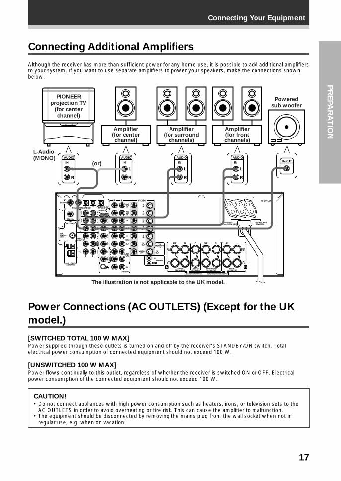
Connecting Additional Amplifiers
Although the receiver has more than sufficient power for any home use, it is possible to add additional amplifiersto your system. If you want to use separate amplifiers to power your speakers, make the connections shownbelow.
Power Connections (AC OUTLETS) (Except for the UK
model.)
[SWITCHED TOTAL 100 W MAX]
Power supplied through these outlets is turned on and off by the receiver’s STANDBY/ON switch. Totalelectrical power consumption of connected equipment should not exceed 100 W.
[UNSWITCHED 100 W MAX]Power flows continually to this outlet, regardless of whether the receiver is switched ON or OFF. Electricalpower consumption of the connected equipment should not exceed 100 W.
CAUTION!• Do not connect appliances with high power consumption such as heaters, irons, or television sets to the
AC OUTLETS in order to avoid overheating or fire risk. This can cause the amplifier to malfunction.• The equipment should be disconnected by removing the mains plug from the wall socket when not in
regular use, e.g. when on vacation.
UNSWITCHED100W MAX
DIGITAL
FMANTENNA
IN
OUT
OUT
IN
IN
IN
VCR2
CONTROL
VCR1
PHONO
TV/SATIN
TOMONITOR
TV
DVD/LDIN
VIDEOOUT
FRONTSPEAKERS
SEE INSTRUCTION MANUAL SE REPORTER AU MODE D’EMPLOI
SURROUNDSPEAKERS
FRONTSPEAKERS
SWITCHED TOTAL 100W MAX
CENTERSPEAKER
MD/TAPE1/CD-R
FM UNBAL75Ω
TAPE2MONITOR
CD
AM LOOPANTENNA
1
PREOUT
2 3 4PCM/ /DTS/MPEG IN
RF IN
PCM/ /DTS/MPEG OUT
R L VIDEO
FR FL C SR SL R L
INS
INS
R L
INS
OUTS
OUTS
OUTS
INS
SR
SL
SL
SR
FR
FL
FL
FRC
C
SW
SW
IN
PLAY
PLAY
PLAY
REC
REC
OUT
EXTERNALDECODER
IN
A B
AC OUTLETS
AUDIO
L
R
IN
AUDIO
L
R
IN
AUDIO
L
R
IN
AUDIO
L
R
IN INPUT
The illustration is not applicable to the UK model.
Amplifier(for center channel)
Amplifier(for surround
channels)
Amplifier(for front channels)
Powered sub woofer
PIONEER projection TV
(for center channel)
L-Audio (MONO)
(or)
18
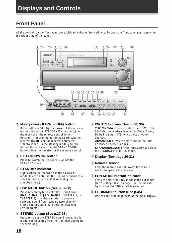
Front Panel
All the controls on the front panel are explained and/or referenced here. To open the front panel push gently onthe lower third of the panel.
1 Main power (— ON/ _ OFF) button
If the button is OFF (_), the power of the receiveris shut off and the STANDBY/ON button (2) onthe receiver or the remote control do notfunction. Pressing the button again will turn thereceiver ON (— ) and the receiver enters thestandby mode. In the standby mode, you canturn on the receiver using the STANDBY/ONbutton (2) on the receiver or the remote control.
2 STANDBY/ON button
Press to switch the receiver ON or into theSTANDBY mode.
3 STANDBY indicator
Lights when the receiver is in the STANDBYmode. (Please note that this receiver consumes asmall amount of power (1.0 W) during thestandby mode.)
4 DSP MODE button (See p.37-38)
Press repeatedly to select a DSP sound mode.(HALL 1, HALL 2, JAZZ, DANCE, THEATER 1, orTHEATER 2). Use these modes to producesurround sound from standard (two channel)stereo sources and create different listeningenvironments.
5 STEREO button (See p.37-38)
Press to select the STEREO sound mode. In thismode, sound comes from the front (left and right)speakers only.
6 2/DTS buttons (See p. 36, 38)
THX CINEMA : Press to select the HOME THXCINEMA mode when listening to Dolby Digital,Dolby Pro Logic, DTS, or a variety of othersources.ADVANCED : Press to select one of the fourAdvanced Theater modes.STANDARD (MPEG ) : Press repeatedly to selectthe STANDARD or MPEG mode.
7 Display (See page 20-21)
8 Remote sensor
Point the remote control toward the remotesensor to operate the receiver.
9 EON MODE button/indicator
Press to select the EON mode in the FM mode(see “Setting EON” on page 53). The indicatorlights when the EON mode is selected.
0 FL DIMMER button (See p.45)
Use to adjust the brightness of the main display.
STANDBY/ON DSPMODESTANDBY
AUDIO/VIDEO MULTI-CHANNEL RECEIVER
STEREO
PHONES S-VIDEO
5-CHANNEL EQUAL POWER OUTPUT
VIDEO
EXTERNALDECODER IN DIRECT LOUDNESS MIDNIGHT
DIGITALNR
SPEAKERS – TREBLE +– BASS +
L AUDIO RVIDEO INPUT
THX CINEMA ADVANCED STANDARD
/DTS
MPEG—OFF _ON
EONMODE
INPUTSELECTOR
MASTERVOLUME
FLDIMMER
DOWN UP
TAPE 2MONITOR
CLASS FM/AM
MEMORYCHARACTER/SEARCHINPUT ATT
– TUNING +
– STATION +
RF ATTSIGNALSELECT
∞
~ ! @ # $ % ^
*()_+¡™£¢
&
21 3 4 5 6 7 8 9 0 - =
Displays and Controls
19
Displays and ControlsP
RE
PA
RA
TIO
N
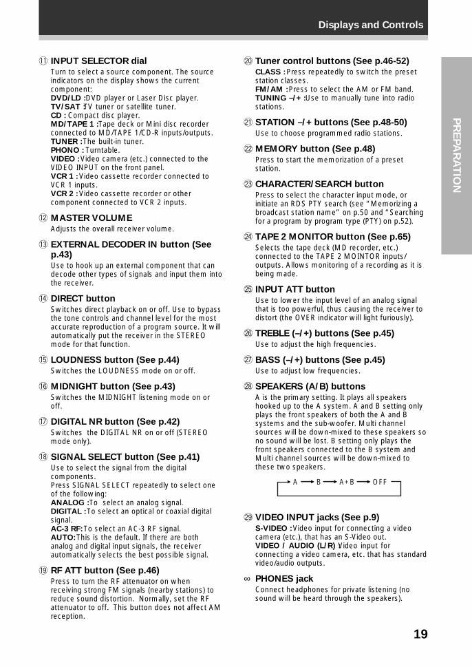
- INPUT SELECTOR dial
Turn to select a source component. The sourceindicators on the display shows the currentcomponent:DVD/LD : DVD player or Laser Disc player.TV/SAT : TV tuner or satellite tuner.CD : Compact disc player.MD/TAPE 1 : Tape deck or Mini disc recorderconnected to MD/TAPE 1/CD-R inputs/outputs.TUNER : The built-in tuner.PHONO : Turntable.VIDEO : Video camera (etc.) connected to theVIDEO INPUT on the front panel.VCR 1 : Video cassette recorder connected toVCR 1 inputs.VCR 2 : Video cassette recorder or othercomponent connected to VCR 2 inputs.
= MASTER VOLUME
Adjusts the overall receiver volume.
~ EXTERNAL DECODER IN button (Seep.43)
Use to hook up an external component that candecode other types of signals and input them intothe receiver.
! DIRECT button
Switches direct playback on or off. Use to bypassthe tone controls and channel level for the mostaccurate reproduction of a program source. It willautomatically put the receiver in the STEREOmode for that function.
@ LOUDNESS button (See p.44)
Switches the LOUDNESS mode on or off.
# MIDNIGHT button (See p.43)
Switches the MIDNIGHT listening mode on oroff.
$ DIGITAL NR button (See p.42)
Switches the DIGITAL NR on or off (STEREOmode only).
% SIGNAL SELECT button (See p.41)
Use to select the signal from the digitalcomponents.Press SIGNAL SELECT repeatedly to select oneof the following:ANALOG : To select an analog signal.DIGITAL : To select an optical or coaxial digitalsignal.AC-3 RF: To select an AC-3 RF signal.AUTO: This is the default. If there are bothanalog and digital input signals, the receiverautomatically selects the best possible signal.
^ RF ATT button (See p.46)
Press to turn the RF attenuator on whenreceiving strong FM signals (nearby stations) toreduce sound distortion. Normally, set the RFattenuator to off. This button does not affect AMreception.
& Tuner control buttons (See p.46-52)
CLASS : Press repeatedly to switch the presetstation classes.FM/AM : Press to select the AM or FM band.TUNING –/+ : Use to manually tune into radiostations.
* STATION –/+ buttons (See p.48-50)
Use to choose programmed radio stations.
( MEMORY button (See p.48)
Press to start the memorization of a presetstation.
) CHARACTER/SEARCH button
Press to select the character input mode, orinitiate an RDS PTY search (see “Memorizing abroadcast station name” on p.50 and “Searchingfor a program by program type (PTY) on p.52).
_ TAPE 2 MONITOR button (See p.65)
Selects the tape deck (MD recorder, etc.)connected to the TAPE 2 MOINTOR inputs/outputs. Allows monitoring of a recording as it isbeing made.
+ INPUT ATT button
Use to lower the input level of an analog signalthat is too powerful, thus causing the receiver todistort (the OVER indicator will light furiously).
¡ TREBLE (–/+) buttons (See p.45)
Use to adjust the high frequencies.
™ BASS (–/+) buttons (See p.45)
Use to adjust low frequencies.
£ SPEAKERS (A/B) buttons
A is the primary setting. It plays all speakershooked up to the A system. A and B setting onlyplays the front speakers of both the A and Bsystems and the sub-woofer. Multi channelsources will be down-mixed to these speakers sono sound will be lost. B setting only plays thefront speakers connected to the B system andMulti channel sources will be down-mixed tothese two speakers.
¢ VIDEO INPUT jacks (See p.9)
S-VIDEO : Video input for connecting a videocamera (etc.), that has an S-Video out.VIDEO / AUDIO (L/R) : Video input forconnecting a video camera, etc. that has standardvideo/audio outputs.
∞ PHONES jack
Connect headphones for private listening (nosound will be heard through the speakers).
A A+B OFFB
20
Displays and Controls
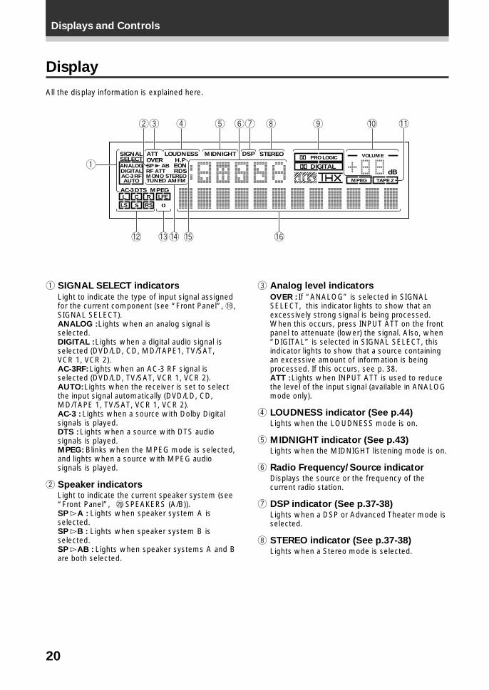
Display
All the display information is explained here.
1 SIGNAL SELECT indicators
Light to indicate the type of input signal assignedfor the current component (see “Front Panel”, %,SIGNAL SELECT).ANALOG : Lights when an analog signal isselected.DIGITAL : Lights when a digital audio signal isselected (DVD/LD, CD, MD/TAPE1, TV/SAT,VCR 1, VCR 2).AC-3RF: Lights when an AC-3 RF signal isselected (DVD/LD, TV/SAT, VCR 1, VCR 2).AUTO: Lights when the receiver is set to selectthe input signal automatically (DVD/LD, CD,MD/TAPE 1, TV/SAT, VCR 1, VCR 2).AC-3 : Lights when a source with Dolby Digitalsignals is played.DTS : Lights when a source with DTS audiosignals is played.MPEG: Blinks when the MPEG mode is selected,and lights when a source with MPEG audiosignals is played.
2 Speaker indicatorsLight to indicate the current speaker system (see“Front Panel”, £, SPEAKERS (A/B)).SP # A : Lights when speaker system A isselected.SP # B : Lights when speaker system B isselected.SP # AB : Lights when speaker systems A and Bare both selected.
3 Analog level indicators
OVER : If “ANALOG” is selected in SIGNALSELECT, this indicator lights to show that anexcessively strong signal is being processed.When this occurs, press INPUT ATT on the frontpanel to attenuate (lower) the signal. Also, when“DIGITAL” is selected in SIGNAL SELECT, thisindicator lights to show that a source containingan excessive amount of information is beingprocessed. If this occurs, see p. 38.ATT : Lights when INPUT ATT is used to reducethe level of the input signal (available in ANALOGmode only).
4 LOUDNESS indicator (See p.44)Lights when the LOUDNESS mode is on.
5 MIDNIGHT indicator (See p.43)Lights when the MIDNIGHT listening mode is on.
6 Radio Frequency/Source indicatorDisplays the source or the frequency of thecurrent radio station.
7 DSP indicator (See p.37-38)Lights when a DSP or Advanced Theater mode isselected.
8 STEREO indicator (See p.37-38)Lights when a Stereo mode is selected.
DIGITALdB
PRO LOGICSTEREODSPMIDNIGHTLOUDNESSATTSIGNAL
SELECT OVER H.P
AC-3DTS MPEG
ANALOG SP AB EONRDSRF ATT
L C R LFE
LS S RS
DIGITALAC-3RF MONO STEREOAUTO TUNED AMFM TAPE 2
VOLUME
MPEG
1
3 4 5 67 8 09 -2
= !~ #@
21
Displays and ControlsP
RE
PA
RA
TIO
N
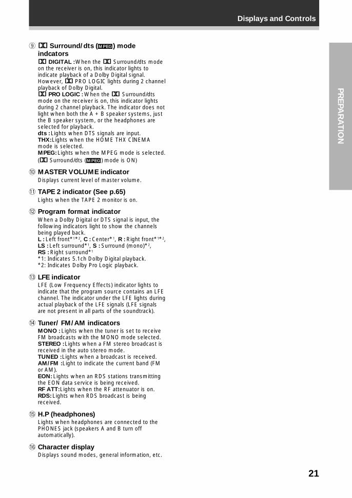
9 2 Surround/dts (MPEG ) mode
indcators
2 DIGITAL : When the 2 Surround/dts modeon the receiver is on, this indicator lights toindicate playback of a Dolby Digital signal.However, 2 PRO LOGIC lights during 2 channelplayback of Dolby Digital.2 PRO LOGIC : When the 2 Surround/dtsmode on the receiver is on, this indicator lightsduring 2 channel playback. The indicator does notlight when both the A + B speaker systems, justthe B speaker system, or the headphones areselected for playback.dts : Lights when DTS signals are input.THX: Lights when the HOME THX CINEMAmode is selected.MPEG: Lights when the MPEG mode is selected.(2 Surround/dts (MPEG ) mode is ON)
0 MASTER VOLUME indicator
Displays current level of master volume.
- TAPE 2 indicator (See p.65)
Lights when the TAPE 2 monitor is on.
= Program format indicator
When a Dolby Digital or DTS signal is input, thefollowing indicators light to show the channelsbeing played back.L : Left front*1*2, C : Center*1, R : Right front*1*2,LS : Left surround*1, S : Surround (mono)*2,RS : Right surround*1
*1: Indicates 5.1ch Dolby Digital playback.*2: Indicates Dolby Pro Logic playback.
~ LFE indicatorLFE (Low Frequency Effects) indicator lights toindicate that the program source contains an LFEchannel. The indicator under the LFE lights duringactual playback of the LFE signals (LFE signalsare not present in all parts of the soundtrack).
! Tuner/ FM/AM indicatorsMONO : Lights when the tuner is set to receiveFM broadcasts with the MONO mode selected.STEREO : Lights when a FM stereo broadcast isreceived in the auto stereo mode.TUNED : Lights when a broadcast is received.AM/FM : Light to indicate the current band (FMor AM).EON: Lights when an RDS stations transmittingthe EON data service is being received.RF ATT: Lights when the RF attenuator is on.RDS: Lights when RDS broadcast is beingreceived.
@ H.P (headphones)Lights when headphones are connected to thePHONES jack (speakers A and B turn offautomatically).
# Character displayDisplays sound modes, general information, etc.
22
Displays and Controls
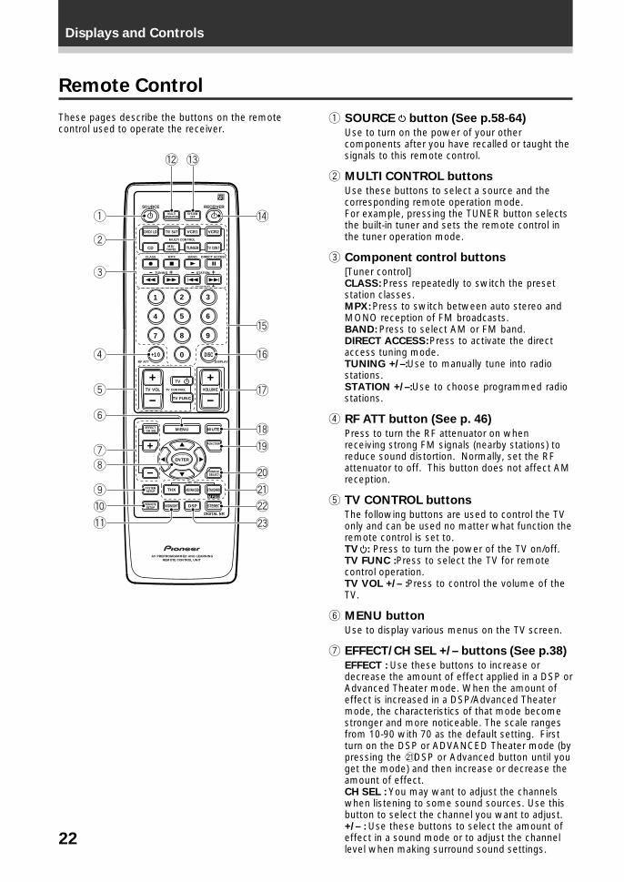
Remote Control
1 SOURCE button (See p.58-64)
Use to turn on the power of your othercomponents after you have recalled or taught thesignals to this remote control.
2 MULTI CONTROL buttons
Use these buttons to select a source and thecorresponding remote operation mode.For example, pressing the TUNER button selectsthe built-in tuner and sets the remote control inthe tuner operation mode.
3 Component control buttons
[Tuner control]CLASS: Press repeatedly to switch the presetstation classes.MPX: Press to switch between auto stereo andMONO reception of FM broadcasts.BAND: Press to select AM or FM band.DIRECT ACCESS: Press to activate the directaccess tuning mode.TUNING +/–: Use to manually tune into radiostations.STATION +/–: Use to choose programmed radiostations.
4 RF ATT button (See p. 46)
Press to turn the RF attenuator on whenreceiving strong FM signals (nearby stations) toreduce sound distortion. Normally, set the RFattenuator to off. This button does not affect AMreception.
5 TV CONTROL buttons
The following buttons are used to control the TVonly and can be used no matter what function theremote control is set to.TV : Press to turn the power of the TV on/off.TV FUNC : Press to select the TV for remotecontrol operation.TV VOL +/– : Press to control the volume of theTV.
6 MENU button
Use to display various menus on the TV screen.
7 EFFECT/CH SEL +/– buttons (See p.38)
EFFECT : Use these buttons to increase ordecrease the amount of effect applied in a DSP orAdvanced Theater mode. When the amount ofeffect is increased in a DSP/Advanced Theatermode, the characteristics of that mode becomestronger and more noticeable. The scale rangesfrom 10-90 with 70 as the default setting. Firstturn on the DSP or ADVANCED Theater mode (bypressing the * DSP or Advanced button until youget the mode) and then increase or decrease theamount of effect.CH SEL : You may want to adjust the channelswhen listening to some sound sources. Use thisbutton to select the channel you want to adjust.+/– : Use these buttons to select the amount ofeffect in a sound mode or to adjust the channellevel when making surround sound settings.
These pages describe the buttons on the remotecontrol used to operate the receiver.
S0URCE
DVD/LD TV/SAT VCR1 VCR2
CD
TV VOL
TV FUNC
MENU
ENTER
STEREO
DIGITAL NR
MIDNIGHT
ADVANCED STANDARD
DSP
THX
MUTE
TV
VOLUME
MD/TAPE1 TUNER TV CONT
RECEIVER
MULTIOPERATION
CLASS MPX
MULTI CONTROL
DIRECT ACCESS
STATION
CHANNEL
TUNING
DISPLAYRF ATT
TV CONTROL
FUNCTION
SIGNALSELECT
EFFECT/CH SEL
2/dts
AV PREPROGRAMMED AND LEARNINGREMOTE CONTROL UNIT
REMOTESETUP
SYSTEMSETUP
BAND
SYSTEMOFF
1 2 3
4 5 6
7
+10
8 9
0 DISC
Î
¶ 7 3 8
1 ¡ 4 ¢ +- +-
+-
MPEG
1
2
3
5
6
78
9
4
0
-
!
= ~
@
#
$
%
^
&
*
(
)
23
Displays and ControlsP
RE
PA
RA
TIO
N
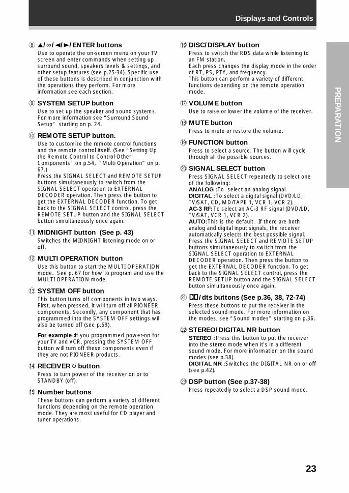
8 5/∞/2/3/ENTER buttons
Use to operate the on-screen menu on your TVscreen and enter commands when setting upsurround sound, speakers levels & settings, andother setup features (see p.25-34). Specific useof these buttons is described in conjunction withthe operations they perform. For moreinformation see each section.
9 SYSTEM SETUP button
Use to set up the speaker and sound systems.For more information see “Surround SoundSetup” starting on p. 24.
0 REMOTE SETUP button.
Use to customize the remote control functionsand the remote control itself. (See “Setting Upthe Remote Control to Control OtherComponents” on p.54, “Multi Operation” on p.67.)Press the SIGNAL SELECT and REMOTE SETUPbuttons simultaneously to switch from theSIGNAL SELECT operation to EXTERNALDECODER operation. Then press the button toget the EXTERNAL DECODER function. To getback to the SIGNAL SELECT control, press theREMOTE SETUP button and the SIGNAL SELECTbutton simultaneously once again.
- MIDNIGHT button (See p. 43)
Switches the MIDNIGHT listening mode on oroff.
= MULTI OPERATION button
Use this button to start the MULTI OPERATIONmode. See p. 67 for how to program and use theMULTI OPERATION mode.
~ SYSTEM OFF button
This button turns off components in two ways.First, when pressed, it will turn off all PIONEERcomponents. Secondly, any component that hasprogrammed into the SYSTEM OFF settings willalso be turned off (see p.69).
For example : If you programmed power-on foryour TV and VCR, pressing the SYSTEM OFFbutton will turn off these components even ifthey are not PIONEER products.
! RECEIVER button
Press to turn power of the receiver on or toSTANDBY (off).
@ Number buttons
These buttons can perform a variety of differentfunctions depending on the remote operationmode. They are most useful for CD player andtuner operations.
# DISC/DISPLAY button
Press to switch the RDS data while listening toan FM station.Each press changes the display mode in the orderof RT, PS, PTY, and frequency.This button can perform a variety of differentfunctions depending on the remote operationmode.
$ VOLUME button
Use to raise or lower the volume of the receiver.
% MUTE button
Press to mute or restore the volume.
^ FUNCTION button
Press to select a source. The button will cyclethrough all the possible sources.
& SIGNAL SELECT button
Press SIGNAL SELECT repeatedly to select oneof the following:ANALOG : To select an analog signal.DIGITAL : To select a digital signal (DVD/LD,TV/SAT, CD, MD/TAPE 1, VCR 1, VCR 2).AC-3 RF: To select an AC-3 RF signal (DVD/LD,TV/SAT, VCR 1, VCR 2).AUTO: This is the default. If there are bothanalog and digital input signals, the receiverautomatically selects the best possible signal.Press the SIGNAL SELECT and REMOTE SETUPbuttons simultaneously to switch from theSIGNAL SELECT operation to EXTERNALDECODER operation. Then press the button toget the EXTERNAL DECODER function. To getback to the SIGNAL SELECT control, press theREMOTE SETUP button and the SIGNAL SELECTbutton simultaneously once again.
* 2/dts buttons (See p.36, 38, 72-74)
Press these buttons to put the receiver in theselected sound mode. For more information onthe modes, see “Sound modes” starting on p.36.
( STEREO/DIGITAL NR button
STEREO : Press this button to put the receiverinto the stereo mode when it’s in a differentsound mode. For more information on the soundmodes (see p.38).DIGITAL NR : Switches the DIGITAL NR on or off(see p.42).
) DSP button (See p.37-38)
Press repeatedly to select a DSP sound mode.
24
Surround Sound Set Up
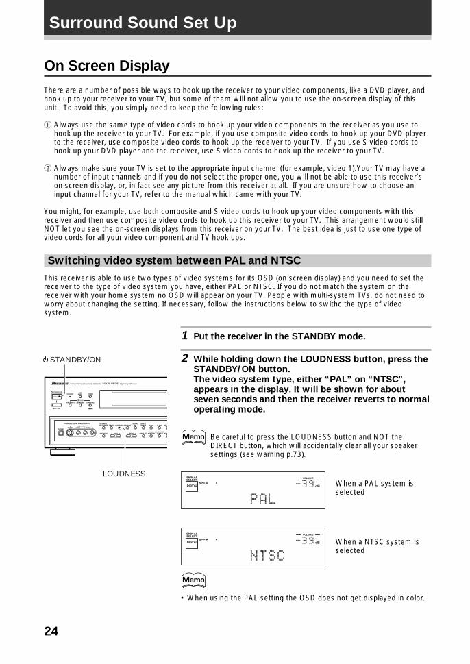
Switching video system between PAL and NTSC
This receiver is able to use two types of video systems for its OSD (on screen display) and you need to set thereceiver to the type of video system you have, either PAL or NTSC. If you do not match the system on thereceiver with your home system no OSD will appear on your TV. People with multi-system TVs, do not need toworry about changing the setting. If necessary, follow the instructions below to swithc the type of videosystem.
1 Put the receiver in the STANDBY mode.
2 While holding down the LOUDNESS button, press theSTANDBY/ON button.The video system type, either “PAL” on “NTSC”,appears in the display. It will be shown for aboutseven seconds and then the receiver reverts to normaloperating mode.
Be careful to press the LOUDNESS button and NOT theDIRECT button, which will accidentally clear all your speakersettings (see warning p.73).
dB
SIGNALSELECT
SP ADIGITAL
VOLUME
dB
SIGNALSELECT
SP ADIGITAL
VOLUME
• When using the PAL setting the OSD does not get displayed in color.
When a PAL system isselected
When a NTSC system isselected
STANDBY/ON
—OFF _ON
DSPMODESTANDBY
AUDIO/VIDEO MULTI-CHANNEL RECEIVER
STEREO
PHONES S-VIDEO
5-CHANNEL EQUAL POWER OUTPUT
VIDEO
EXTERNALDECODER IN
TAPE 2MONITOR
DIRECT LOUDNESS MIDNIGHTDIGITAL
NR CLASS FM/
MEMCHARACTER/SEARCHINPUT ATTSPEAKERS – TREBLE +– BASS +
L AUDIO RVIDEO INPUT
THX CINEMA ADVANCED STANDARD
/DTS
MPEG
RF ATTSIGNALSELECT
LOUDNESS
STANDBY/ON
On Screen Display
There are a number of possible ways to hook up the receiver to your video components, like a DVD player, andhook up to your receiver to your TV, but some of them will not allow you to use the on-screen display of thisunit. To avoid this, you simply need to keep the following rules:
1 Always use the same type of video cords to hook up your video components to the receiver as you use tohook up the receiver to your TV. For example, if you use composite video cords to hook up your DVD playerto the receiver, use composite video cords to hook up the receiver to your TV. If you use S video cords tohook up your DVD player and the receiver, use S video cords to hook up the receiver to your TV.
2 Always make sure your TV is set to the appropriate input channel (for example, video 1).Your TV may have anumber of input channels and if you do not select the proper one, you will not be able to use this receiver’son-screen display, or, in fact see any picture from this receiver at all. If you are unsure how to choose aninput channel for your TV, refer to the manual which came with your TV.
You might, for example, use both composite and S video cords to hook up your video components with thisreceiver and then use composite video cords to hook up this receiver to your TV. This arrangement would stillNOT let you see the on-screen displays from this receiver on your TV. The best idea is just to use one type ofvideo cords for all your video component and TV hook ups.
25
Surround Sound Set UpS
ET
UP
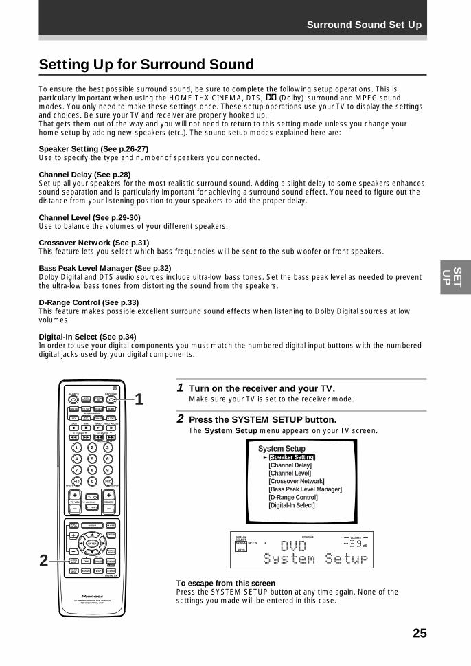
Setting Up for Surround Sound
To ensure the best possible surround sound, be sure to complete the following setup operations. This isparticularly important when using the HOME THX CINEMA, DTS, 2 (Dolby) surround and MPEG soundmodes. You only need to make these settings once. These setup operations use your TV to display the settingsand choices. Be sure your TV and receiver are properly hooked up.That gets them out of the way and you will not need to return to this setting mode unless you change yourhome setup by adding new speakers (etc.). The sound setup modes explained here are:
Speaker Setting (See p.26-27)Use to specify the type and number of speakers you connected.
Channel Delay (See p.28)Set up all your speakers for the most realistic surround sound. Adding a slight delay to some speakers enhancessound separation and is particularly important for achieving a surround sound effect. You need to figure out thedistance from your listening position to your speakers to add the proper delay.
Channel Level (See p.29-30)Use to balance the volumes of your different speakers.
Crossover Network (See p.31)This feature lets you select which bass frequencies will be sent to the sub woofer or front speakers.
Bass Peak Level Manager (See p.32)Dolby Digital and DTS audio sources include ultra-low bass tones. Set the bass peak level as needed to preventthe ultra-low bass tones from distorting the sound from the speakers.
D-Range Control (See p.33)This feature makes possible excellent surround sound effects when listening to Dolby Digital sources at lowvolumes.
Digital-In Select (See p.34)In order to use your digital components you must match the numbered digital input buttons with the numbereddigital jacks used by your digital components.
1 Turn on the receiver and your TV.Make sure your TV is set to the receiver mode.
2 Press the SYSTEM SETUP button.
The System Setup menu appears on your TV screen.
System Setup [Speaker Setting] [Channel Delay] [Channel Level] [Crossover Network] [Bass Peak Level Manager] [D-Range Control] [Digital-In Select]
dB
STEREOSIGNALSELECTANALOG SP A
AUTO
VOLUME
To escape from this screenPress the SYSTEM SETUP button at any time again. None of thesettings you made will be entered in this case.
S0URCE
DVD/LD TV/SAT VCR1 VCR2
CD
TV VOL
TV FUNC
MENU
ENTER
STEREO
DIGITAL NR
MIDNIGHT
ADVANCED STANDARD
DSP
THX
MUTE
TV
VOLUME
MD/TAPE1 TUNER TV CONT
RECEIVER
MULTIOPERATION
CLASS MPX
MULTI CONTROL
DIRECT ACCESS
STATION
CHANNEL
TUNING
DISPLAYRF ATT
TV CONTROL
FUNCTION
SIGNALSELECT
EFFECT/CH SEL
2/dts
AV PREPROGRAMMED AND LEARNINGREMOTE CONTROL UNIT
REMOTESETUP
SYSTEMSETUP
BAND
SYSTEMOFF
1 2 3
4 5 6
7
+10
8 9
0 DISC
Î
¶ 7 3 8
1 ¡ 4 ¢ +- +-
+-
MPEG2
1
26
Surround Sound Set Up
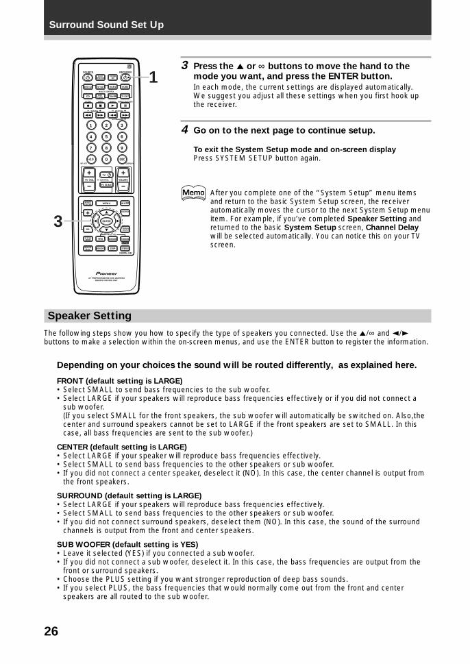
Speaker Setting
The following steps show you how to specify the type of speakers you connected. Use the 5¥∞ and 2¥3buttons to make a selection within the on-screen menus, and use the ENTER button to register the information.
Depending on your choices the sound will be routed differently, as explained here.
FRONT (default setting is LARGE)• Select SMALL to send bass frequencies to the sub woofer.• Select LARGE if your speakers will reproduce bass frequencies effectively or if you did not connect a
sub woofer.(If you select SMALL for the front speakers, the sub woofer will automatically be switched on. Also,thecenter and surround speakers cannot be set to LARGE if the front speakers are set to SMALL. In thiscase, all bass frequencies are sent to the sub woofer.)
CENTER (default setting is LARGE)• Select LARGE if your speaker will reproduce bass frequencies effectively.• Select SMALL to send bass frequencies to the other speakers or sub woofer.• If you did not connect a center speaker, deselect it (NO). In this case, the center channel is output from
the front speakers.
SURROUND (default setting is LARGE)• Select LARGE if your speakers will reproduce bass frequencies effectively.• Select SMALL to send bass frequencies to the other speakers or sub woofer.• If you did not connect surround speakers, deselect them (NO). In this case, the sound of the surround
channels is output from the front and center speakers.
SUB WOOFER (default setting is YES)• Leave it selected (YES) if you connected a sub woofer.• If you did not connect a sub woofer, deselect it. In this case, the bass frequencies are output from the
front or surround speakers.• Choose the PLUS setting if you want stronger reproduction of deep bass sounds.• If you select PLUS, the bass frequencies that would normally come out from the front and center
speakers are all routed to the sub woofer.
3 Press the 5 or ∞ buttons to move the hand to themode you want, and press the ENTER button.
In each mode, the current settings are displayed automatically.We suggest you adjust all these settings when you first hook upthe receiver.
4 Go on to the next page to continue setup.
To exit the System Setup mode and on-screen displayPress SYSTEM SETUP button again.
After you complete one of the “System Setup” menu itemsand return to the basic System Setup screen, the receiverautomatically moves the cursor to the next System Setup menuitem. For example, if you’ve completed Speaker Setting andreturned to the basic System Setup screen, Channel Delaywill be selected automatically. You can notice this on your TVscreen.
S0URCE
DVD/LD TV/SAT VCR1 VCR2
CD
TV VOL
TV FUNC
MENU
ENTER
STEREO
DIGITAL NR
MIDNIGHT
ADVANCED STANDARD
DSP
THX
MUTE
TV
VOLUME
MD/TAPE1 TUNER TV CONT
RECEIVER
MULTIOPERATION
CLASS MPX
MULTI CONTROL
DIRECT ACCESS
STATION
CHANNEL
TUNING
DISPLAYRF ATT
TV CONTROL
FUNCTION
SIGNALSELECT
EFFECT/CH SEL
2/dts
AV PREPROGRAMMED AND LEARNINGREMOTE CONTROL UNIT
REMOTESETUP
SYSTEMSETUP
BAND
SYSTEMOFF
1 2 3
4 5 6
7
+10
8 9
0 DISC
Î
¶ 7 3 8
1 ¡ 4 ¢ +- +-
+-
MPEG
3
1
27
Surround Sound Set UpS
ET
UP
S0URCE
DVD/LD TV/SAT VCR1 VCR2
CD
TV VOL
TV FUNC
MENU
ENTER
STEREO
DIGITAL NR
MIDNIGHT
ADVANCED STANDARD
DSP
THX
MUTE
TV
VOLUME
MD/TAPE1 TUNER TV CONT
RECEIVER
MULTIOPERATION
CLASS MPX
MULTI CONTROL
DIRECT ACCESS
STATION
CHANNEL
TUNING
DISPLAYRF ATT
TV CONTROL
FUNCTION
SIGNALSELECT
EFFECT/CH SEL
2/dts
AV PREPROGRAMMED AND LEARNINGREMOTE CONTROL UNIT
REMOTESETUP
SYSTEMSETUP
BAND
SYSTEMOFF
1 2 3
4 5 6
7
+10
8 9
0 DISC
Î
¶ 7 3 8
1 ¡ 4 ¢ +- +-
+-
MPEG
1-4
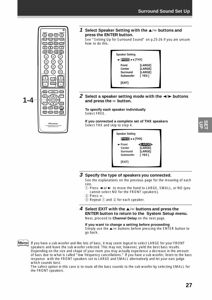
1 Select Speaker Setting with the 5¥∞ buttons andpress the ENTER button.See “Setting Up for Surround Sound” on p.25-26 if you are unsurehow to do this.
Speaker Setting
[FREE] [THX]
[LARGE][LARGE][LARGE][ YES ]
Front LCenterSurround Subwoofer
[EXIT]
2 Select a speaker setting mode with the 2¥3 buttonsand press the ∞ button.
To specify each speaker individuallySelect FREE.
If you connected a complete set of THX speakersSelect THX and skip to step 4.
Speaker Setting
[FREE] [THX]
[LARGE][LARGE][LARGE][ YES ]
Front LCenterSurround Subwoofer
[EXIT]
3 Specify the type of speakers you connected.
See the explanations on the previous page for the meaning of eachsize.1 Press 2 or 3 to move the hand to LARGE, SMALL, or NO (you
cannot select NO for the FRONT speakers).2 Press ∞ .3 Repeat 1 and 2 for each speaker.
4 Select EXIT with the 5¥∞ buttons and press theENTER button to return to the System Setup menu.Next, proceed to Channel Delay on the next page.
If you want to change a setting before proceedingSimply use the 5¥∞ buttons before pressing the ENTER button togo back.
If you have a sub woofer and like lots of bass, it may seem logical to select LARGE for your FRONTspeakers and leave the sub woofer selected. This may not, however, yield the best bass results.Depending on the size and shape of your room you may actually experience a decrease in the amountof bass due to what is called “low frequency cancellations.” If you have a sub woofer, listen to the bassresponse with the FRONT speakers set to LARGE and SMALL alternatively and let your ears judgewhich sounds best.The safest option in this case is to route all the bass sounds to the sub woofer by selecting SMALL forthe FRONT speakers.
28
Surround Sound Set Up
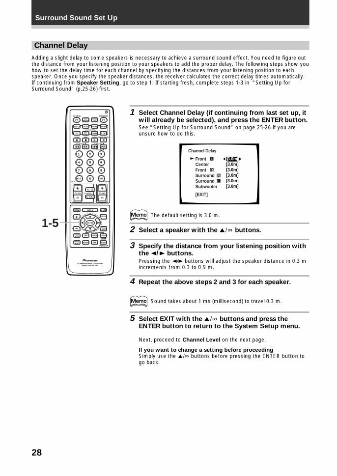
Channel Delay
Adding a slight delay to some speakers is necessary to achieve a surround sound effect. You need to figure outthe distance from your listening position to your speakers to add the proper delay. The following steps show youhow to set the delay time for each channel by specifying the distances from your listening position to eachspeaker. Once you specify the speaker distances, the receiver calculates the correct delay times automatically.If continuing from Speaker Setting, go to step 1. If starting fresh, complete steps 1-3 in “Setting Up forSurround Sound” (p.25-26) first.
1 Select Channel Delay (if continuing from last set up, itwill already be selected), and press the ENTER button.See “Setting Up for Surround Sound” on page 25-26 if you areunsure how to do this.
Channel Delay
Front LCenterFrontSurround SurroundSubwoofer
[EXIT]
L
RRL
[3.0m][3.0m][3.0m][3.0m] [3.0m][3.0m]
The default setting is 3.0 m.
2 Select a speaker with the 5¥∞ buttons.
3 Specify the distance from your listening position withthe 2/3 buttons.
Pressing the 2/3 buttons will adjust the speaker distance in 0.3 mincrements from 0.3 to 0.9 m.
4 Repeat the above steps 2 and 3 for each speaker.
Sound takes about 1 ms (millisecond) to travel 0.3 m.
5 Select EXIT with the 5¥∞ buttons and press theENTER button to return to the System Setup menu.
Next, proceed to Channel Level on the next page.
If you want to change a setting before proceedingSimply use the 5¥∞ buttons before pressing the ENTER button togo back.
S0URCE
DVD/LD TV/SAT VCR1 VCR2
CD
TV VOL
TV FUNC
MENU
ENTER
STEREO
DIGITAL NR
MIDNIGHT
ADVANCED STANDARD
DSP
THX
MUTE
TV
VOLUME
MD/TAPE1 TUNER TV CONT
RECEIVER
MULTIOPERATION
CLASS MPX
MULTI CONTROL
DIRECT ACCESS
STATION
CHANNEL
TUNING
DISPLAYRF ATT
TV CONTROL
FUNCTION
SIGNALSELECT
EFFECT/CH SEL
2/dts
AV PREPROGRAMMED AND LEARNINGREMOTE CONTROL UNIT
REMOTESETUP
SYSTEMSETUP
BAND
SYSTEMOFF
1 2 3
4 5 6
7
+10
8 9
0 DISC
Î
¶ 7 3 8
1 ¡ 4 ¢ +- +-
+-
MPEG
1-5
29
Surround Sound Set UpS
ET
UP
Channel Level
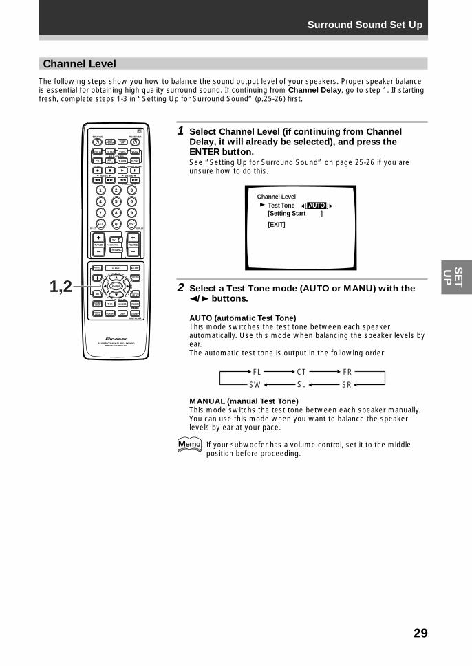
The following steps show you how to balance the sound output level of your speakers. Proper speaker balanceis essential for obtaining high quality surround sound. If continuing from Channel Delay, go to step 1. If startingfresh, complete steps 1-3 in “Setting Up for Surround Sound” (p.25-26) first.
1 Select Channel Level (if continuing from ChannelDelay, it will already be selected), and press theENTER button.See “Setting Up for Surround Sound” on page 25-26 if you areunsure how to do this.
Channel LevelTest Tone [ AUTO ][Setting Start ]
[EXIT]
2 Select a Test Tone mode (AUTO or MANU) with the2/3 buttons.
AUTO (automatic Test Tone)This mode switches the test tone between each speakerautomatically. Use this mode when balancing the speaker levels byear.The automatic test tone is output in the following order:
FL CT FR
SRSLSW
MANUAL (manual Test Tone)This mode switchs the test tone between each speaker manually.You can use this mode when you want to balance the speakerlevels by ear at your pace.
If your subwoofer has a volume control, set it to the middleposition before proceeding.
S0URCE
DVD/LD TV/SAT VCR1 VCR2
CD
TV VOL
TV FUNC
MENU
ENTER
STEREO
DIGITAL NR
MIDNIGHT
ADVANCED STANDARD
DSP
THX
MUTE
TV
VOLUME
MD/TAPE1 TUNER TV CONT
RECEIVER
MULTIOPERATION
CLASS MPX
MULTI CONTROL
DIRECT ACCESS
STATION
CHANNEL
TUNING
DISPLAYRF ATT
TV CONTROL
FUNCTION
SIGNALSELECT
EFFECT/CH SEL
2/dts
AV PREPROGRAMMED AND LEARNINGREMOTE CONTROL UNIT
REMOTESETUP
SYSTEMSETUP
BAND
SYSTEMOFF
1 2 3
4 5 6
7
+10
8 9
0 DISC
Î
¶ 7 3 8
1 ¡ 4 ¢ +- +-
+-
MPEG
1,2
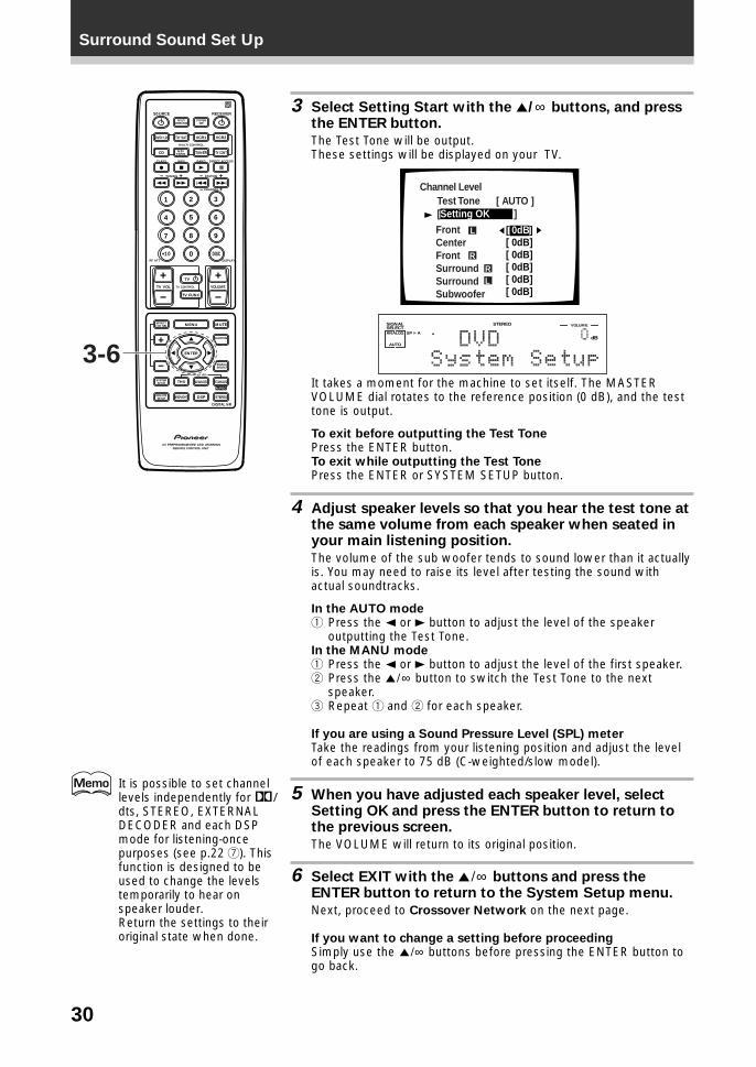
30
Surround Sound Set Up
3 Select Setting Start with the 5/∞ buttons, and pressthe ENTER button.
The Test Tone will be output.These settings will be displayed on your TV.
Channel Level
Front LCenterFrontSurround SurroundSubwoofer
L
RRL
Test Tone [ AUTO ][Setting OK ]
[ 0dB][ 0dB][ 0dB][ 0dB] [ 0dB][ 0dB]
dB
STEREOSIGNALSELECTANALOG SP A
AUTO
VOLUME
It takes a moment for the machine to set itself. The MASTERVOLUME dial rotates to the reference position (0 dB), and the testtone is output.
To exit before outputting the Test TonePress the ENTER button.To exit while outputting the Test TonePress the ENTER or SYSTEM SETUP button.
4 Adjust speaker levels so that you hear the test tone atthe same volume from each speaker when seated inyour main listening position.
The volume of the sub woofer tends to sound lower than it actuallyis. You may need to raise its level after testing the sound withactual soundtracks.
In the AUTO mode1 Press the 2 or 3 button to adjust the level of the speaker
outputting the Test Tone.In the MANU mode1 Press the 2 or 3 button to adjust the level of the first speaker.2 Press the 5¥∞ button to switch the Test Tone to the next
speaker.3 Repeat 1 and 2 for each speaker.
If you are using a Sound Pressure Level (SPL) meterTake the readings from your listening position and adjust the levelof each speaker to 75 dB (C-weighted/slow model).
5 When you have adjusted each speaker level, selectSetting OK and press the ENTER button to return tothe previous screen.
The VOLUME will return to its original position.
6 Select EXIT with the 5¥∞ buttons and press theENTER button to return to the System Setup menu.
Next, proceed to Crossover Network on the next page.
If you want to change a setting before proceedingSimply use the 5¥∞ buttons before pressing the ENTER button togo back.
S0URCE
DVD/LD TV/SAT VCR1 VCR2
CD
TV VOL
TV FUNC
MENU
ENTER
STEREO
DIGITAL NR
MIDNIGHT
ADVANCED STANDARD
DSP
THX
MUTE
TV
VOLUME
MD/TAPE1 TUNER TV CONT
RECEIVER
MULTIOPERATION
CLASS MPX
MULTI CONTROL
DIRECT ACCESS
STATION
CHANNEL
TUNING
DISPLAYRF ATT
TV CONTROL
FUNCTION
SIGNALSELECT
EFFECT/CH SEL
2/dts
AV PREPROGRAMMED AND LEARNINGREMOTE CONTROL UNIT
REMOTESETUP
SYSTEMSETUP
BAND
SYSTEMOFF
1 2 3
4 5 6
7
+10
8 9
0 DISC
Î
¶ 7 3 8
1 ¡ 4 ¢ +- +-
+-
MPEG
3-6
It is possible to set channellevels independently for 2/dts, STEREO, EXTERNALDECODER and each DSPmode for listening-oncepurposes (see p.22 7). Thisfunction is designed to beused to change the levelstemporarily to hear onspeaker louder.Return the settings to theiroriginal state when done.
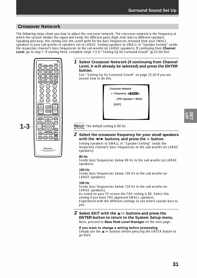
31
Surround Sound Set UpS
ET
UP
Crossover Network
The following steps show you how to adjust the crossover network. The crossover network is the frequency atwhich the system divides the signal and sends the different parts (high ,mid, low) to different speakers.Speaking precisely, this setting sets the cutoff point for the bass frequencies rerouted from your SMALLspeakers to your sub woofer or speakers set to LARGE. Setting speakers to SMALL in “Speaker Setting” sendsthe respective channel’s bass frequencies to the sub woofer (or LARGE speakers). If continuing from ChannelLevel, go to step 1. If starting fresh, complete steps 1-3 in “Setting Up for Surround Sound” (p.25-26) first.
1 Select Crossover Network (if continuing from ChannelLevel, it will already be selected) and press the ENTERbutton.See “Setting Up for Surround Sound” on page 25-26 if you areunsure how to do this.
Crossover Network
Frequency [ 80Hz ] (THX Speaker = 80Hz)
[EXIT]
The default setting is 80 Hz.
2 Select the crossover frequency for your small speakerswith the 2/3 buttons, and press the ∞ button.
Setting speakers to SMALL in “Speaker Setting” sends therespective channel’s bass frequencies to the sub woofer (or LARGEspeakers).
80 HzSends bass frequencies below 80 Hz to the sub woofer (or LARGEspeakers).
100 HzSends bass frequencies below 100 Hz to the sub woofer (orLARGE speakers).
150 HzSends bass frequencies below 150 Hz to the sub woofer (orLARGE speakers).As noted on your TV screen the THX setting is 80. Select thissetting if you have THX approved SMALL speakers.Experiment with the different settings to see which sounds best toyou.
3 Select EXIT with the 5¥∞ buttons and press theENTER button to return to the System Setup menu.Next, proceed to Bass Peak Level Manager on the next page.
If you want to change a setting before proceedingSimply use the 5¥∞ buttons before pressing the ENTER button togo back.
S0URCE
DVD/LD TV/SAT VCR1 VCR2
CD
TV VOL
TV FUNC
MENU
ENTER
STEREO
DIGITAL NR
MIDNIGHT
ADVANCED STANDARD
DSP
THX
MUTE
TV
VOLUME
MD/TAPE1 TUNER TV CONT
RECEIVER
MULTIOPERATION
CLASS MPX
MULTI CONTROL
DIRECT ACCESS
STATION
CHANNEL
TUNING
DISPLAYRF ATT
TV CONTROL
FUNCTION
SIGNALSELECT
EFFECT/CH SEL
2/dts
AV PREPROGRAMMED AND LEARNINGREMOTE CONTROL UNIT
REMOTESETUP
SYSTEMSETUP
BAND
SYSTEMOFF
1 2 3
4 5 6
7
+10
8 9
0 DISC
Î
¶ 7 3 8
1 ¡ 4 ¢ +- +-
+-
MPEG
1-3
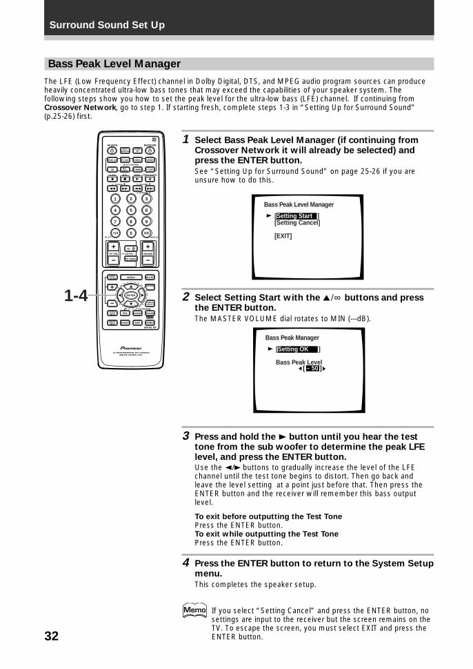
32
Surround Sound Set Up
Bass Peak Level Manager
The LFE (Low Frequency Effect) channel in Dolby Digital, DTS, and MPEG audio program sources can produceheavily concentrated ultra-low bass tones that may exceed the capabilities of your speaker system. Thefollowing steps show you how to set the peak level for the ultra-low bass (LFE) channel. If continuing fromCrossover Network, go to step 1. If starting fresh, complete steps 1-3 in “Setting Up for Surround Sound”(p.25-26) first.
1 Select Bass Peak Level Manager (if continuing fromCrossover Network it will already be selected) andpress the ENTER button.
See “Setting Up for Surround Sound” on page 25-26 if you areunsure how to do this.
Bass Peak Level Manager
[Setting Start ][Setting Cancel]
[EXIT]
2 Select Setting Start with the 5¥∞ buttons and pressthe ENTER button.
The MASTER VOLUME dial rotates to MIN (---dB).
Bass Peak Manager
[ – 50 ] [ ]
[Setting OK ]
Bass Peak Level
3 Press and hold the 3 button until you hear the testtone from the sub woofer to determine the peak LFElevel, and press the ENTER button.Use the 2/3 buttons to gradually increase the level of the LFEchannel until the test tone begins to distort. Then go back andleave the level setting at a point just before that. Then press theENTER button and the receiver will remember this bass outputlevel.
To exit before outputting the Test TonePress the ENTER button.To exit while outputting the Test TonePress the ENTER button.
4 Press the ENTER button to return to the System Setupmenu.
This completes the speaker setup.
If you select “Setting Cancel” and press the ENTER button, nosettings are input to the receiver but the screen remains on theTV. To escape the screen, you must select EXIT and press theENTER button.
S0URCE
DVD/LD TV/SAT VCR1 VCR2
CD
TV VOL
TV FUNC
MENU
ENTER
STEREO
DIGITAL NR
MIDNIGHT
ADVANCED STANDARD
DSP
THX
MUTE
TV
VOLUME
MD/TAPE1 TUNER TV CONT
RECEIVER
MULTIOPERATION
CLASS MPX
MULTI CONTROL
DIRECT ACCESS
STATION
CHANNEL
TUNING
DISPLAYRF ATT
TV CONTROL
FUNCTION
SIGNALSELECT
EFFECT/CH SEL
2/dts
AV PREPROGRAMMED AND LEARNINGREMOTE CONTROL UNIT
REMOTESETUP
SYSTEMSETUP
BAND
SYSTEMOFF
1 2 3
4 5 6
7
+10
8 9
0 DISC
Î
¶ 7 3 8
1 ¡ 4 ¢ +- +-
+-
MPEG
1-4

33
Surround Sound Set UpS
ET
UP
D-Range Control
This feature makes it possible to enjoy full surround sound effects on Dolby Digital sources even at lowvolumes. It does this by compressing the dynamic range. Dynamic range is the difference between the loudestand the softest sounds in any given signal. Compressing the range plays sounds so the quieter ones are audibleand the louder ones do not get distorted or become overpowering. This feature only applies to Dolby Digitalsources but the MIDNIGHT listening mode accomplishes the same end for a variety of sources (see p.43). Ifcontinuing from Bass Peak Level Manager, go to step 1. If starting fresh, complete steps 1-3 in “Setting Up forSurround Sound” (p.25-26) first.
1 Select D-Range Control (if continuing from Bass PeakLevel Manager, it will already be selected) and pressthe ENTER button.
See “Setting Up for Surround Sound” on page 25-26 if you areunsure how to do this.
Dynamic Range Control
Select Mode [ OFF ]
(For Dolby Digital)
[EXIT]
• The default setting is OFF.• If listening at high volumes, we recommend turning the
Dynamic Range Control OFF.
2 Select OFF, MID or MAX with the 2/3 buttons.
3 Select EXIT with the 5¥∞ buttons and press theENTER button to return to the System Setup menu.
If you want to change a setting before proceedingSimply use the 5¥∞ buttons before pressing the ENTER button togo back.Choose a new D-Range Control setting.You may need to experiment with different Dolby Digital sourcesbefore you can use D-Range Control setting to suit your lowvolume listening needs.
S0URCE
DVD/LD TV/SAT VCR1 VCR2
CD
TV VOL
TV FUNC
MENU
ENTER
STEREO
DIGITAL NR
MIDNIGHT
ADVANCED STANDARD
DSP
THX
MUTE
TV
VOLUME
MD/TAPE1 TUNER TV CONT
RECEIVER
MULTIOPERATION
CLASS MPX
MULTI CONTROL
DIRECT ACCESS
STATION
CHANNEL
TUNING
DISPLAYRF ATT
TV CONTROL
FUNCTION
SIGNALSELECT
EFFECT/CH SEL
2/dts
AV PREPROGRAMMED AND LEARNINGREMOTE CONTROL UNIT
REMOTESETUP
SYSTEMSETUP
BAND
SYSTEMOFF
1 2 3
4 5 6
7
+10
8 9
0 DISC
Î
¶ 7 3 8
1 ¡ 4 ¢ +- +-
+-
MPEG
1-3
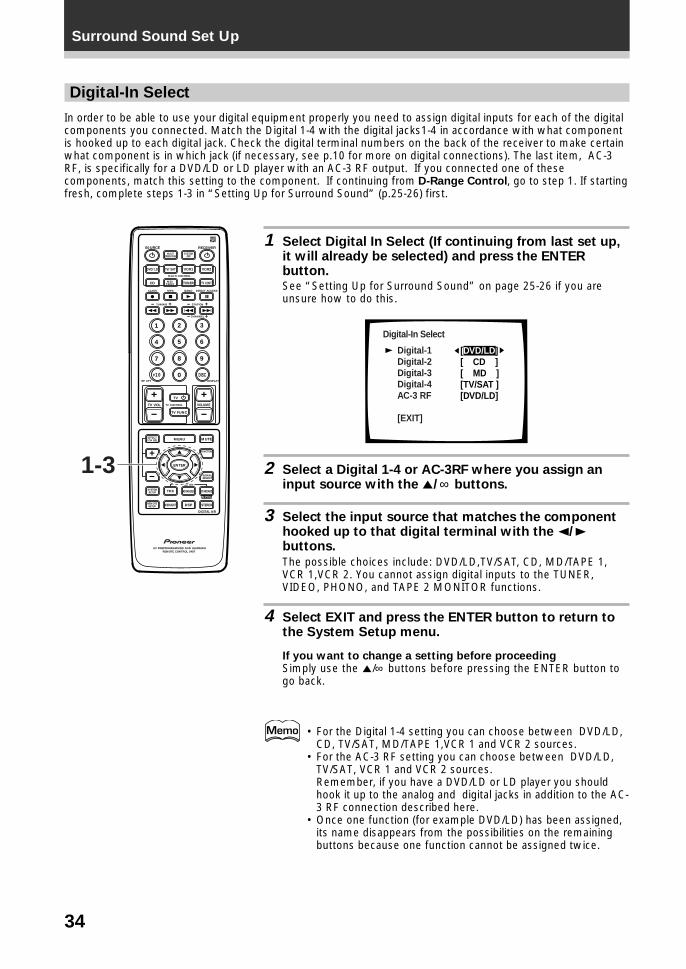
34
Surround Sound Set Up
Digital-In Select
In order to be able to use your digital equipment properly you need to assign digital inputs for each of the digitalcomponents you connected. Match the Digital 1-4 with the digital jacks1-4 in accordance with what componentis hooked up to each digital jack. Check the digital terminal numbers on the back of the receiver to make certainwhat component is in which jack (if necessary, see p.10 for more on digital connections). The last item, AC-3RF, is specifically for a DVD/LD or LD player with an AC-3 RF output. If you connected one of thesecomponents, match this setting to the component. If continuing from D-Range Control, go to step 1. If startingfresh, complete steps 1-3 in “Setting Up for Surround Sound” (p.25-26) first.
1 Select Digital In Select (If continuing from last set up,it will already be selected) and press the ENTERbutton.See “Setting Up for Surround Sound” on page 25-26 if you areunsure how to do this.
Digital-In Select
Digital-1Digital-2Digital-3Digital-4AC-3 RF
[EXIT] L
[DVD/LD][ CD ][ MD ][TV/SAT ][DVD/LD]
2 Select a Digital 1-4 or AC-3RF where you assign aninput source with the 5/∞ buttons.
3 Select the input source that matches the componenthooked up to that digital terminal with the 2/3buttons.
The possible choices include: DVD/LD,TV/SAT, CD, MD/TAPE 1,VCR 1,VCR 2. You cannot assign digital inputs to the TUNER,VIDEO, PHONO, and TAPE 2 MONITOR functions.
4 Select EXIT and press the ENTER button to return tothe System Setup menu.
If you want to change a setting before proceedingSimply use the 5/∞ buttons before pressing the ENTER button togo back.
• For the Digital 1-4 setting you can choose between DVD/LD,CD, TV/SAT, MD/TAPE 1,VCR 1 and VCR 2 sources.
• For the AC-3 RF setting you can choose between DVD/LD,TV/SAT, VCR 1 and VCR 2 sources.Remember, if you have a DVD/LD or LD player you shouldhook it up to the analog and digital jacks in addition to the AC-3 RF connection described here.
• Once one function (for example DVD/LD) has been assigned,its name disappears from the possibilities on the remainingbuttons because one function cannot be assigned twice.
THX
S0URCE
DVD/LD TV/SAT VCR1 VCR2
CD
TV VOL
TV FUNC
MENU
ENTER
STEREO
DIGITAL NR
MIDNIGHT
ADVANCED STANDARD
DSP
MUTE
TV
VOLUME
MD/TAPE1 TUNER TV CONT
RECEIVER
MULTIOPERATION
CLASS MPX
MULTI CONTROL
DIRECT ACCESS
STATION
CHANNEL
TUNING
DISPLAYRF ATT
TV CONTROL
FUNCTION
SIGNALSELECT
EFFECT/CH SEL
2/dts
AV PREPROGRAMMED AND LEARNINGREMOTE CONTROL UNIT
REMOTESETUP
SYSTEMSETUP
BAND
SYSTEMOFF
1 2 3
4 5 6
7
+10
8 9
0 DISC
Î
¶ 7 3 8
1 ¡ 4 ¢ +- +-
+-
MPEG
1-3
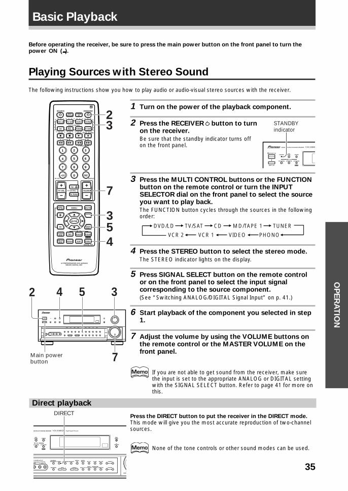
35
OP
ER
AT
ION
Before operating the receiver, be sure to press the main power button on the front panel to turn thepower ON (_).
Playing Sources with Stereo Sound
The following instructions show you how to play audio or audio-visual stereo sources with the receiver.
1 Turn on the power of the playback component.
2 Press the RECEIVER button to turnon the receiver.
Be sure that the standby indicator turns offon the front panel.
3 Press the MULTI CONTROL buttons or the FUNCTIONbutton on the remote control or turn the INPUTSELECTOR dial on the front panel to select the sourceyou want to play back.
The FUNCTION button cycles through the sources in the followingorder:
TUNERMD/TAPE 1
VCR 2 VCR 1
TV/SATDVD/LD CD
VIDEO PHONO
4 Press the STEREO button to select the stereo mode.
The STEREO indicator lights on the display.
5 Press SIGNAL SELECT button on the remote controlor on the front panel to select the input signalcorresponding to the source component.
(See “Switching ANALOG/DIGITAL Signal Input” on p. 41.)
6 Start playback of the component you selected in step1.
7 Adjust the volume by using the VOLUME buttons onthe remote control or the MASTER VOLUME on thefront panel.
If you are not able to get sound from the receiver, make surethe input is set to the appropriate ANALOG or DIGITAL settingwith the SIGNAL SELECT button. Refer to page 41 for more onthis.
S0URCE
DVD/LD TV/SAT VCR1 VCR2
CD
TV VOL
TV FUNC
MENU
ENTER
STEREO
DIGITAL NR
MIDNIGHT
ADVANCED STANDARD
DSP
THX
MUTE
TV
VOLUME
MD/TAPE1 TUNER TV CONT
RECEIVER
MULTIOPERATION
CLASS MPX
MULTI CONTROL
DIRECT ACCESS
STATION
CHANNEL
TUNING
DISPLAYRF ATT
TV CONTROL
FUNCTION
SIGNALSELECT
EFFECT/CH SEL
2/dts
AV PREPROGRAMMED AND LEARNINGREMOTE CONTROL UNIT
REMOTESETUP
SYSTEMSETUP
BAND
SYSTEMOFF
1 2 3
4 5 6
7
+10
8 9
0 DISC
Î
¶ 7 3 8
1 ¡ 4 ¢ +- +-
+-
MPEG
23
7
35
4
2 3
7
4 5
Main power button
STANDBY/ON
—OFF _ON
DSPMODESTANDBY
AUDIO/VIDEO MULTI-CHANNEL RECEIVER
STEREO
THX CINEMA ADVANCED STANDARD
/DTS
MPEG
STANDBYindicator
Basic Playback
DSPMODE
EONMODE
FLDIMMER
DEO MULTI-CHANNEL RECEIVER
STEREO
L POWER OUTPUT
IDEO
EXTERNALDECODER IN
TAPE 2MONITOR
DIRECT LOUDNESS MIDNIGHTDIGITAL
NR CLASS FM/AM
MEMORYCHARACTER/SEARCHINPUT ATTSPEAKERS
– TUNING +
– STATION +– TREBLE +– BASS +
L AUDIO RVIDEO INPUT
ADVANCED STANDARD
/DTS
MPEG
DOWN
RF ATTSIGNALSELECT
DIRECT
Direct playback
Press the DIRECT button to put the receiver in the DIRECT mode.This mode will give you the most accurate reproduction of two-channelsources.
None of the tone controls or other sound modes can be used.
36
Basic Playback
Sound Modes
The six sound modes on the receiver are explained here. These can be turned on from the front panel or fromthe remote control.There are four cinema modes: MPEG, STANDARD, HOME THX CINEMA and ADVANCED THEATER. These aredesigned to be used with multi channel surround sound audio/visual sources (like DVDs and LDs). Intrinsic tohome theater, these modes can deliver realistic and powerful surround sound that recreates the movie theaterexperience. You may need to experiment with them to see which settings suit your home system and personaltastes.The DSP and STEREO modes are designed to be used with music sources but some DSP modes are also suitedfor film soundtracks. Again, try different settings with various soundtracks to see which you like.You must choose one of the four cinema modes or the DSP mode in order to get surround sound. In STEREOmode only the front two speakers are used.
MPEG mode
Use this mode to enjoy playback of software recorded in MPEG audio. For more detailed information, see p.74.
STANDARD mode
This mode is for pure decoding of Dolby Digital, DTS and Dolby Pro Logic. No special effects are added. It isgood for enjoying movies that have been recorded in Dolby Digital, DTS or Dolby Surround.
HOME THX CINEMA mode
THX is a set of technical standards created by Lucasfilm, Ltd. These standards were designed to emulate a filmsound stage and thus reproduce, with the greatest possible accuracy, the soundtrack intended by thefilmmakers. For more detailed information, see p.74.
ADVANCED THEATER modes
The Advanced Theater mode is a newly designed system for enhancing movie soundtracks and other audio-visual sources. It incorporates the use of DTS (Digital Theater System) as well as Dolby Digital into its soundprocessing. These functions switch on automatically when the source you are playing is encoded with DTS,Dolby Pro Logic or Dolby Digital (bearing the 1 logo). There are four Advanced Theater settings that useDSP (Digital Signal Processing) to create different types of sound environments.
MUSICAL
This mode is primarily for music and adds a spacious feeling to the sound. A long delay time of reflectedsounds, provides resonant tones which emulate a concert hall.
DRAMA (CINEMA)This mode is designed for movies with a lot of dialog. The elements of dialog are enhanced, making thecharacters seem more real. The mode also compresses the dynamic range somewhat so loud sounds do notoverpower softer ones (compare this with the MIDNIGHT Listening mode explained on p.43).
ACTION
This mode is designed for action movies, which generally use lots of sound effects. The mode enriches thesound to make it more realistic and extends the parameters to pick up high and low sound effects.
5-D THEATER
This mode is especially designed to give sound depth to stereo sources. The overall effect builds a dynamicand broad sound space, allowing two-channel (stereo) signals to faithfully imitate a five speaker sound. Themode should be used in conjunction with Dolby Pro Logic for sources bearing the 3 mark.
When a Dolby Digital soundtracks is played back, the Dialog Normalization function of the receiveractivates automatically. Dialog Normalization is a Dolby Digital function that establishes the averagedialog level for the program source being played. If the receiver’s level does not match the averagedialog level, first you see “DIAL.NORM” flashes and then “OFFSET +4dB” (as an example) appears inthe receiver’s display. The number +4dB is the difference between the receiver’s gain structure andthe Dolby Digital average dialog level. To match the average dialog level, subtract or add the OFFSETlevel. For example, if the OFFSET level is +4dB, turn the MASTER VOLUME dial down so 4dB issubtracted from the current level.
37
Basic PlaybackO
PE
RA
TIO
N
DSP modes
The DSP (Digital Signal Processing) modes allow you to transform your living room into a variety of differentsonic environments when playing either two-channel or multi-channel sources.
HALL 1
Simulates the acoustic effects of a large concert hall. Suitable for classical music.A long delay time of reflected sounds, coupled with reverb effects, lets the listener enjoy the dynamic andrich sounds characteristic of concert halls and powerful orchestral performances.
HALL 2
Simulates the acoustic environment of a very resonant concert hall. Rich reverberation and a full soundcreate the impression of a lively performance space.
JAZZ
Simulates the acoustic effects of a jazz club. Reflected sound is virtually below 100 msec so that the listenercan enjoy a live band effect.
DANCESimulates the acoustic effects of a dance club. Features a strong bass sound.Reflected sound delay time is virtually below 50 msec, for the listener to enjoy the the visceral power ofdance music.
THEATER 1
Reproduces theater sound field effects without losing the localization of each channel. Theater effects canbe enjoyed without losing Dolby Digital/ Pro Logic effects when used in combination those formats (withmovies bearing the 3 trademark).
THEATER 2
Simulates the acoustic environment of a theater while maintaining proper localization of each channel.
Stereo mode
Use the STEREO mode to enjoy standard (two-channel) stereo sound from the front left and right speakers.
This mode also allows you to :• Use the BASS and TREBLE tone controls• Use DIRECT for truer reproduction of the original recording.• Use DIGITAL NR.
See display explanations on p.20-21 and front panel explanations on p.18-19 for details on SPEAKERS (A/B),LOUDNESS, BASS (–/+) and TREBLE (–/+).
When listening to Dolby Digital or DTS sources, DIGITAL NR do not function even if you selectSTEREO.
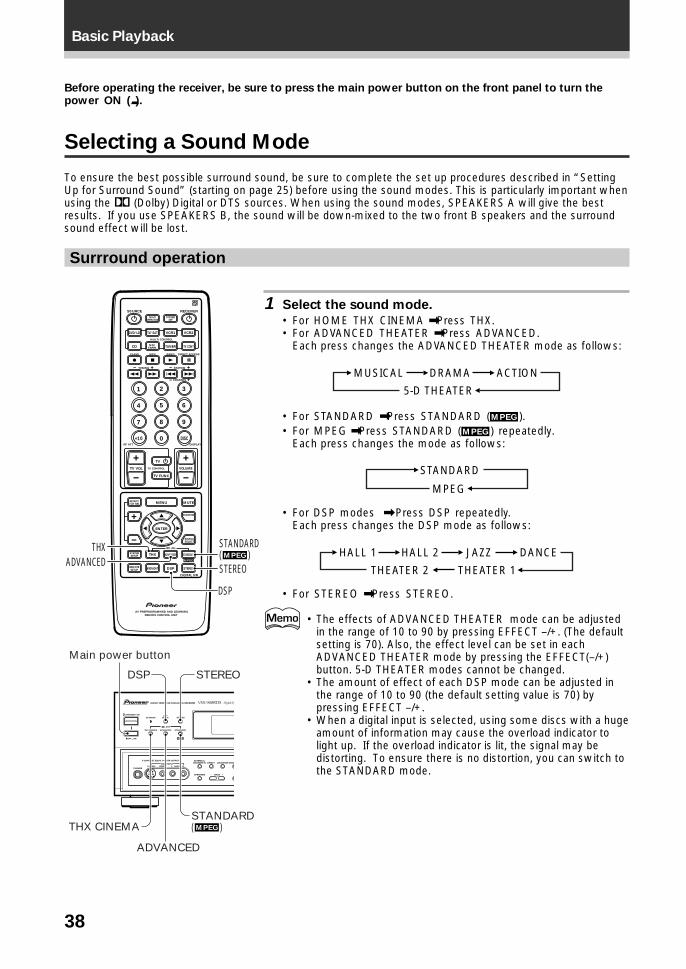
38
Basic Playback
Before operating the receiver, be sure to press the main power button on the front panel to turn thepower ON (_).
Selecting a Sound Mode
To ensure the best possible surround sound, be sure to complete the set up procedures described in “SettingUp for Surround Sound” (starting on page 25) before using the sound modes. This is particularly important whenusing the 2 (Dolby) Digital or DTS sources. When using the sound modes, SPEAKERS A will give the bestresults. If you use SPEAKERS B, the sound will be down-mixed to the two front B speakers and the surroundsound effect will be lost.
Surrround operation
1 Select the sound mode.
• For HOME THX CINEMA \ Press THX.• For ADVANCED THEATER \ Press ADVANCED.
Each press changes the ADVANCED THEATER mode as follows:
5-D THEATER
DRAMAMUSICAL ACTION
• For STANDARD \ Press STANDARD (MPEG ).• For MPEG \ Press STANDARD (MPEG ) repeatedly.
Each press changes the mode as follows:
STANDARD
MPEG
• For DSP modes \ Press DSP repeatedly.Each press changes the DSP mode as follows:
THEATER 2 THEATER 1
HALL 2HALL 1 JAZZ DANCE
• For STEREO \ Press STEREO.
• The effects of ADVANCED THEATER mode can be adjustedin the range of 10 to 90 by pressing EFFECT –/+. (The defaultsetting is 70). Also, the effect level can be set in eachADVANCED THEATER mode by pressing the EFFECT(–/+)button. 5-D THEATER modes cannot be changed.
• The amount of effect of each DSP mode can be adjusted inthe range of 10 to 90 (the default setting value is 70) bypressing EFFECT –/+.
• When a digital input is selected, using some discs with a hugeamount of information may cause the overload indicator tolight up. If the overload indicator is lit, the signal may bedistorting. To ensure there is no distortion, you can switch tothe STANDARD mode.
S0URCE
DVD/LD TV/SAT VCR1 VCR2
CD
TV VOL
TV FUNC
MENU
ENTER
STEREO
DIGITAL NR
MIDNIGHT
ADVANCED STANDARD
DSP
THX
MUTE
TV
VOLUME
MD/TAPE1 TUNER TV CONT
RECEIVER
MULTIOPERATION
CLASS MPX
MULTI CONTROL
DIRECT ACCESS
STATION
CHANNEL
TUNING
DISPLAYRF ATT
TV CONTROL
FUNCTION
SIGNALSELECT
EFFECT/CH SEL
2/dts
AV PREPROGRAMMED AND LEARNINGREMOTE CONTROL UNIT
REMOTESETUP
SYSTEMSETUP
BAND
SYSTEMOFF
1 2 3
4 5 6
7
+10
8 9
0 DISC
Î
¶ 7 3 8
1 ¡ 4 ¢ +- +-
+-
MPEG
STANDARD( )
ADVANCEDTHX
DSP
STEREOMPEG
STANDBY/ON
—OFF _ON
DSPMODESTANDBY
AUDIO/VIDEO MULTI-CHANNEL RECEIVER
STEREO
PHONES S-VIDEO
5-CHANNEL EQUAL POWER OUTPUT
VIDEO
EXTERNALDECODER IN DIRECT LOUDNESS MIDN
SPEAKERS –– BASS +
L AUDIO RVIDEO INPUT
THX CINEMA ADVANCED STANDARD
/DTS
MPEG
DSP STEREO
STANDARD( )THX CINEMA
ADVANCED
Main power button
MPEG
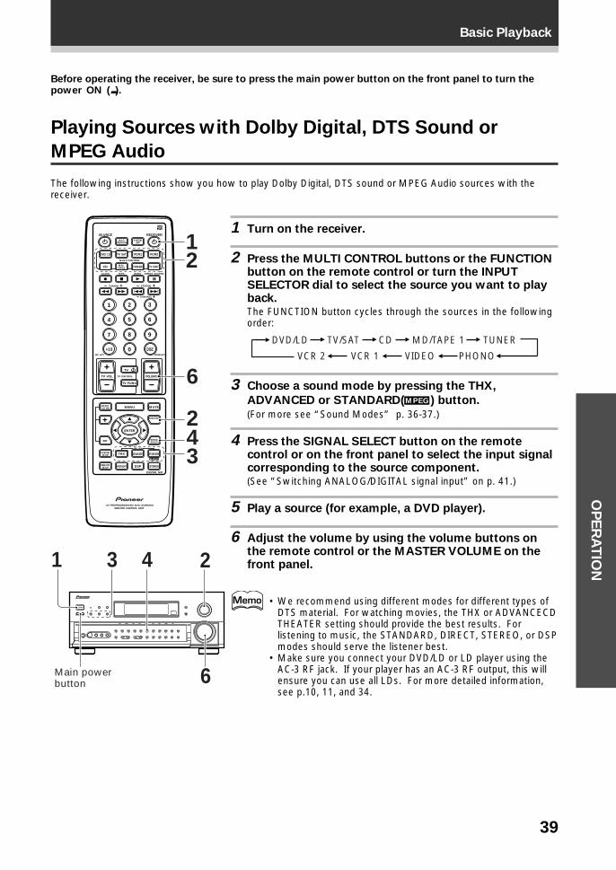
39
Basic PlaybackO
PE
RA
TIO
N
Before operating the receiver, be sure to press the main power button on the front panel to turn thepower ON (_).
Playing Sources with Dolby Digital, DTS Sound or
MPEG Audio
The following instructions show you how to play Dolby Digital, DTS sound or MPEG Audio sources with thereceiver.
1 Turn on the receiver.
2 Press the MULTI CONTROL buttons or the FUNCTIONbutton on the remote control or turn the INPUTSELECTOR dial to select the source you want to playback.The FUNCTION button cycles through the sources in the followingorder:
TUNERMD/TAPE 1
VCR 2 VCR 1
TV/SATDVD/LD CD
VIDEO PHONO
3 Choose a sound mode by pressing the THX,
ADVANCED or STANDARD(MPEG ) button.
(For more see “Sound Modes” p. 36-37.)
4 Press the SIGNAL SELECT button on the remotecontrol or on the front panel to select the input signalcorresponding to the source component.(See “Switching ANALOG/DIGITAL signal input” on p. 41.)
5 Play a source (for example, a DVD player).
6 Adjust the volume by using the volume buttons onthe remote control or the MASTER VOLUME on thefront panel.
• We recommend using different modes for different types ofDTS material. For watching movies, the THX or ADVANCECDTHEATER setting should provide the best results. Forlistening to music, the STANDARD, DIRECT, STEREO, or DSPmodes should serve the listener best.
• Make sure you connect your DVD/LD or LD player using theAC-3 RF jack. If your player has an AC-3 RF output, this willensure you can use all LDs. For more detailed information,see p.10, 11, and 34.
S0URCE
DVD/LD TV/SAT VCR1 VCR2
CD
TV VOL
TV FUNC
MENU
ENTER
STEREO
DIGITAL NR
MIDNIGHT
ADVANCED STANDARD
DSP
THX
MUTE
TV
VOLUME
MD/TAPE1 TUNER TV CONT
RECEIVER
MULTIOPERATION
CLASS MPX
MULTI CONTROL
DIRECT ACCESS
STATION
CHANNEL
TUNING
DISPLAYRF ATT
TV CONTROL
FUNCTION
SIGNALSELECT
EFFECT/CH SEL
2/dts
AV PREPROGRAMMED AND LEARNINGREMOTE CONTROL UNIT
REMOTESETUP
SYSTEMSETUP
BAND
SYSTEMOFF
1 2 3
4 5 6
7
+10
8 9
0 DISC
Î
¶ 7 3 8
1 ¡ 4 ¢ +- +-
+-
MPEG
12
6
42
3
1 23 4
6Main power button
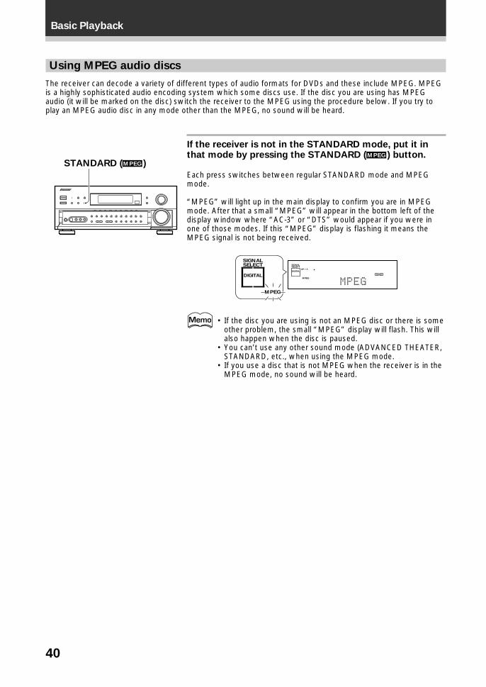
40
Basic Playback
Using MPEG audio discs
The receiver can decode a variety of different types of audio formats for DVDs and these include MPEG. MPEGis a highly sophisticated audio encoding system which some discs use. If the disc you are using has MPEGaudio (it will be marked on the disc) switch the receiver to the MPEG using the procedure below. If you try toplay an MPEG audio disc in any mode other than the MPEG, no sound will be heard.
If the receiver is not in the STANDARD mode, put it inthat mode by pressing the STANDARD (MPEG ) button.
Each press switches between regular STANDARD mode and MPEGmode.
“MPEG” will light up in the main display to confirm you are in MPEGmode. After that a small “MPEG” will appear in the bottom left of thedisplay window where “AC-3” or “DTS” would appear if you were inone of those modes. If this “MPEG” display is flashing it means theMPEG signal is not being received.
SIGNALSELECT
MPEG
DIGITAL
SIGNALSELECT
MPEG
SP ADIGITAL
MPEG
• If the disc you are using is not an MPEG disc or there is someother problem, the small “MPEG” display will flash. This willalso happen when the disc is paused.
• You can’t use any other sound mode (ADVANCED THEATER,STANDARD, etc., when using the MPEG mode.
• If you use a disc that is not MPEG when the receiver is in theMPEG mode, no sound will be heard.
STANDARD (MPEG )
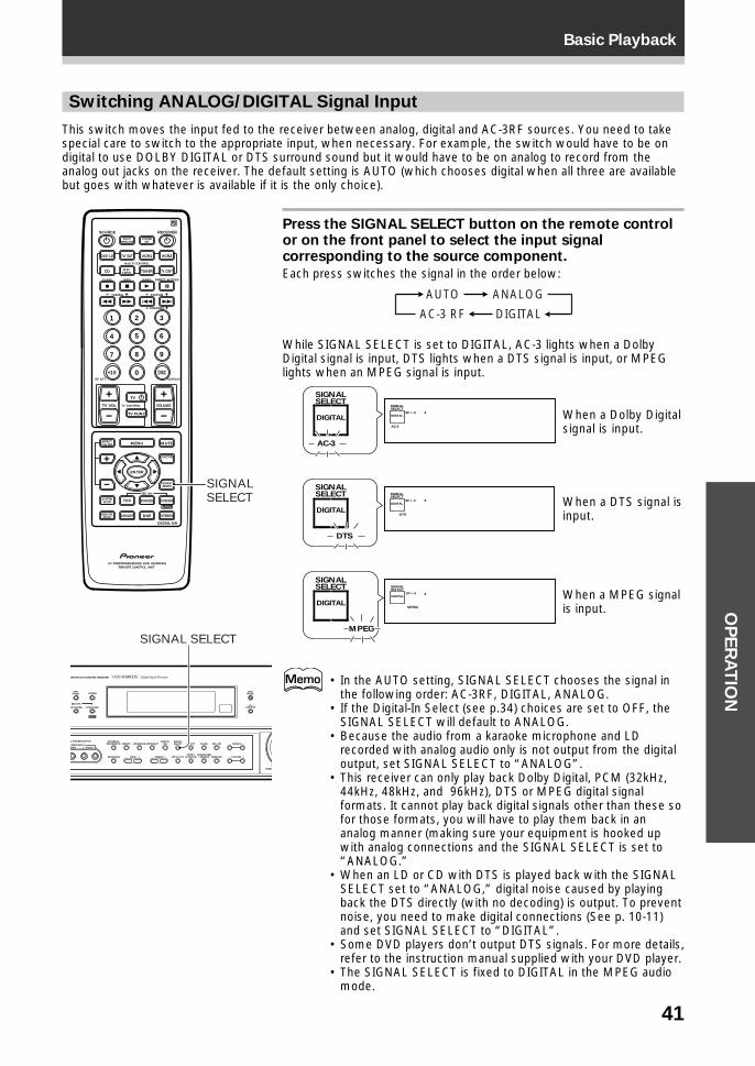
41
Basic PlaybackO
PE
RA
TIO
N
Switching ANALOG/DIGITAL Signal Input
This switch moves the input fed to the receiver between analog, digital and AC-3RF sources. You need to takespecial care to switch to the appropriate input, when necessary. For example, the switch would have to be ondigital to use DOLBY DIGITAL or DTS surround sound but it would have to be on analog to record from theanalog out jacks on the receiver. The default setting is AUTO (which chooses digital when all three are availablebut goes with whatever is available if it is the only choice).
Press the SIGNAL SELECT button on the remote controlor on the front panel to select the input signalcorresponding to the source component.
Each press switches the signal in the order below:
ANALOGAUTO
AC-3 RF DIGITAL
While SIGNAL SELECT is set to DIGITAL, AC-3 lights when a DolbyDigital signal is input, DTS lights when a DTS signal is input, or MPEGlights when an MPEG signal is input.
SIGNALSELECT
DTS
SP ADIGITAL
SIGNALSELECT
AC-3
SP ADIGITAL
SIGNALSELECT
DTS
DIGITAL
SIGNALSELECT
MPEG
SP ADIGITAL
SIGNALSELECT
MPEG
DIGITAL
SIGNALSELECT
AC-3
DIGITAL
• In the AUTO setting, SIGNAL SELECT chooses the signal inthe following order: AC-3RF, DIGITAL, ANALOG.
• If the Digital-In Select (see p.34) choices are set to OFF, theSIGNAL SELECT will default to ANALOG.
• Because the audio from a karaoke microphone and LDrecorded with analog audio only is not output from the digitaloutput, set SIGNAL SELECT to “ANALOG”.
• This receiver can only play back Dolby Digital, PCM (32kHz,44kHz, 48kHz, and 96kHz), DTS or MPEG digital signalformats. It cannot play back digital signals other than these sofor those formats, you will have to play them back in ananalog manner (making sure your equipment is hooked upwith analog connections and the SIGNAL SELECT is set to“ANALOG.”
• When an LD or CD with DTS is played back with the SIGNALSELECT set to “ANALOG,” digital noise caused by playingback the DTS directly (with no decoding) is output. To preventnoise, you need to make digital connections (See p. 10-11)and set SIGNAL SELECT to “DIGITAL”.
• Some DVD players don’t output DTS signals. For more details,refer to the instruction manual supplied with your DVD player.
• The SIGNAL SELECT is fixed to DIGITAL in the MPEG audiomode.
When a Dolby Digitalsignal is input.
When a DTS signal isinput.
S0URCE
DVD/LD TV/SAT VCR1 VCR2
CD
TV VOL
TV FUNC
MENU
ENTER
STEREO
DIGITAL NR
MIDNIGHT
ADVANCED STANDARD
DSP
THX
MUTE
TV
VOLUME
MD/TAPE1 TUNER TV CONT
RECEIVER
MULTIOPERATION
CLASS MPX
MULTI CONTROL
DIRECT ACCESS
STATION
CHANNEL
TUNING
DISPLAYRF ATT
TV CONTROL
FUNCTION
SIGNALSELECT
EFFECT/CH SEL
2/dts
AV PREPROGRAMMED AND LEARNINGREMOTE CONTROL UNIT
REMOTESETUP
SYSTEMSETUP
BAND
SYSTEMOFF
1 2 3
4 5 6
7
+10
8 9
0 DISC
Î
¶ 7 3 8
1 ¡ 4 ¢ +- +-
+-
MPEG
SIGNAL SELECT
DSPMODE
EONMODE
FLDIMMER
DEO MULTI-CHANNEL RECEIVER
STEREO
L POWER OUTPUT
IDEO
EXTERNALDECODER IN
TAPE 2MONITOR
DIRECT LOUDNESS MIDNIGHTDIGITAL
NR CLASS FM/AM
MEMORYCHARACTER/SEARCHINPUT ATTSPEAKERS
– TUNING +
– STATION +– TREBLE +– BASS +
L AUDIO RVIDEO INPUT
ADVANCED STANDARD
/DTS
MPEG
DOWN
RF ATTSIGNALSELECT
SIGNAL SELECT
When a MPEG signalis input.
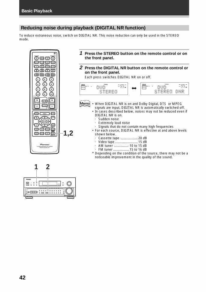
42
Basic Playback
Reducing noise during playback (DIGITAL NR function)
To reduce extraneous noise, switch on DIGITAL NR. This noise reduction can only be used in the STEREOmode.
1 Press the STEREO button on the remote control or onthe front panel.
2 Press the DIGITAL NR button on the remote control oron the front panel.
Each press switches DIGITAL NR on or off.
• When DIGITAL NR is on and Dolby Digital, DTS or MPEGsignals are input, DIGITAL NR is automatically switched off.
• In cases described below, noises may not be reduced even ifDIGITAL NR is on.· Sudden noise· Extremely loud noise· Signals that do not contain many high frequencies
• For each source, DIGITAL NR is effective at and above levelsshown below.· Cassette tape .................. 20 dB· Video tape ........................ 15 dB· AM tuner ............... 10 to 15 dB· FM tuner .................15 to 16 dB
* Depending on the condition of the source, there may not be anoticeable improvement in the quality of the sound.
S0URCE
DVD/LD TV/SAT VCR1 VCR2
CD
TV VOL
TV FUNC
MENU
ENTER
STEREO
DIGITAL NR
MIDNIGHT
ADVANCED STANDARD
DSP
THX
MUTE
TV
VOLUME
MD/TAPE1 TUNER TV CONT
RECEIVER
MULTIOPERATION
CLASS MPX
MULTI CONTROL
DIRECT ACCESS
STATION
CHANNEL
TUNING
DISPLAYRF ATT
TV CONTROL
FUNCTION
SIGNALSELECT
EFFECT/CH SEL
2/dts
AV PREPROGRAMMED AND LEARNINGREMOTE CONTROL UNIT
REMOTESETUP
SYSTEMSETUP
BAND
SYSTEMOFF
1 2 3
4 5 6
7
+10
8 9
0 DISC
Î
¶ 7 3 8
1 ¡ 4 ¢ +- +-
+-
MPEG
1,2
j
21
dB
STEREOSIGNALSELECT
SP ADIGITAL
VOLUME
dB
STEREOSIGNALSELECT
SP ADIGITAL
VOLUME
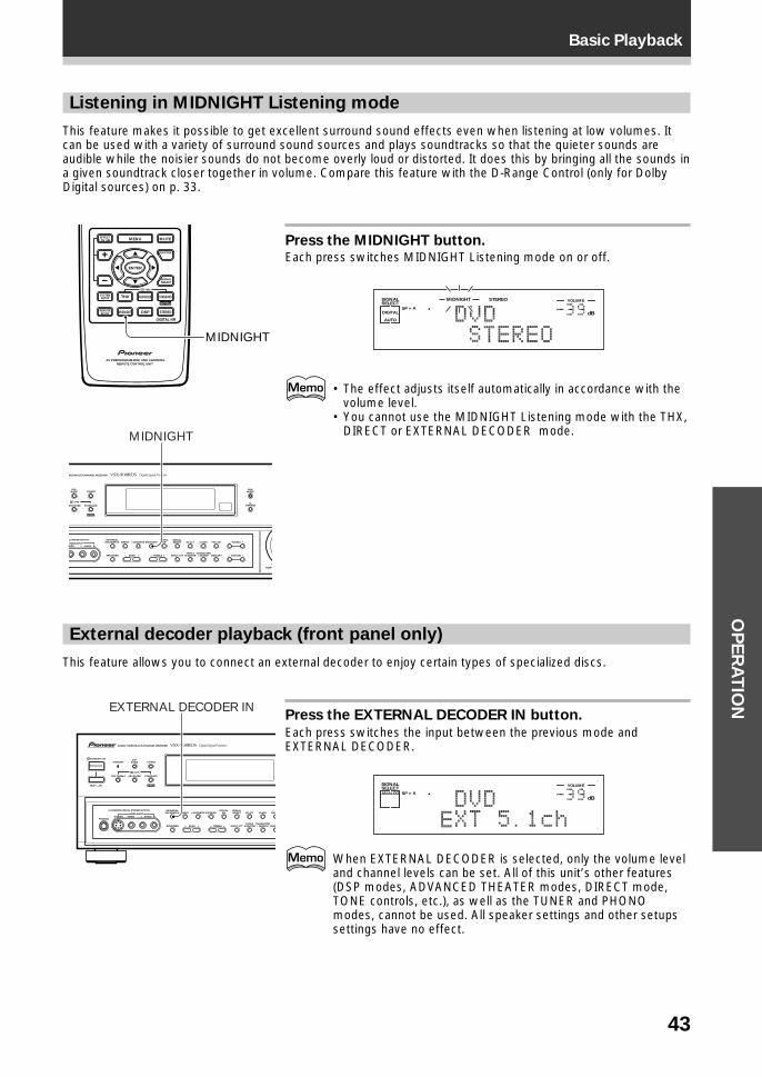
43
Basic PlaybackO
PE
RA
TIO
N
External decoder playback (front panel only)
This feature allows you to connect an external decoder to enjoy certain types of specialized discs.
Press the EXTERNAL DECODER IN button.
Each press switches the input between the previous mode andEXTERNAL DECODER.
dB
SIGNALSELECTANALOG SP A
VOLUME
When EXTERNAL DECODER is selected, only the volume leveland channel levels can be set. All of this unit’s other features(DSP modes, ADVANCED THEATER modes, DIRECT mode,TONE controls, etc.), as well as the TUNER and PHONOmodes, cannot be used. All speaker settings and other setupssettings have no effect.
Listening in MIDNIGHT Listening mode
This feature makes it possible to get excellent surround sound effects even when listening at low volumes. Itcan be used with a variety of surround sound sources and plays soundtracks so that the quieter sounds areaudible while the noisier sounds do not become overly loud or distorted. It does this by bringing all the sounds ina given soundtrack closer together in volume. Compare this feature with the D-Range Control (only for DolbyDigital sources) on p. 33.
Press the MIDNIGHT button.Each press switches MIDNIGHT Listening mode on or off.
dB
STEREOMIDNIGHTSIGNALSELECT
SP ADIGITAL
AUTO
VOLUME
• The effect adjusts itself automatically in accordance with thevolume level.
• You cannot use the MIDNIGHT Listening mode with the THX,DIRECT or EXTERNAL DECODER mode.
DSPMODE
EONMODE
FLDIMMER
DEO MULTI-CHANNEL RECEIVER
STEREO
L POWER OUTPUT
IDEO
EXTERNALDECODER IN
TAPE 2MONITOR
DIRECT LOUDNESS MIDNIGHTDIGITAL
NR CLASS FM/AM
MEMORYCHARACTER/SEARCHINPUT ATTSPEAKERS
– TUNING +
– STATION +– TREBLE +– BASS +
L AUDIO RVIDEO INPUT
ADVANCED STANDARD
/DTS
MPEG
DOWN
RF ATTSIGNALSELECT
MIDNIGHT
STANDBY/ON
—OFF _ON
DSPMODESTANDBY
AUDIO/VIDEO MULTI-CHANNEL RECEIVER
STEREO
PHONES S-VIDEO
5-CHANNEL EQUAL POWER OUTPUT
VIDEO
EXTERNALDECODER IN
TAPE 2MONITOR
DIRECT LOUDNESS MIDNIGHTDIGITAL
NR CLASS FM/
MEMCHARACTER/SEARCHINPUT ATTSPEAKERS – TREBLE +– BASS +
L AUDIO RVIDEO INPUT
THX CINEMA ADVANCED STANDARD
/DTS
MPEG
RF ATTSIGNALSELECT
EXTERNAL DECODER IN
MENU
ENTER
STEREO
DIGITAL NR
MIDNIGHT
ADVANCED STANDARD
DSP
THX
MUTE
FUNCTION
SIGNALSELECT
EFFECT/CH SEL
2/dts
AV PREPROGRAMMED AND LEARNINGREMOTE CONTROL UNIT
REMOTESETUP
SYSTEMSETUP
MPEG
MIDNIGHT
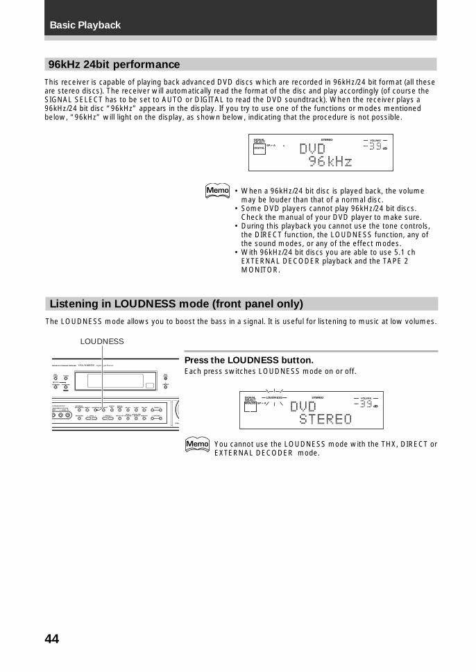
44
Basic Playback
96kHz 24bit performance
This receiver is capable of playing back advanced DVD discs which are recorded in 96kHz/24 bit format (all theseare stereo discs). The receiver will automatically read the format of the disc and play accordingly (of course theSIGNAL SELECT has to be set to AUTO or DIGITAL to read the DVD soundtrack). When the receiver plays a96kHz/24 bit disc “96kHz” appears in the display. If you try to use one of the functions or modes mentionedbelow, “96kHz” will light on the display, as shown below, indicating that the procedure is not possible.
dB
STEREOSIGNALSELECT
SP ADIGITAL
VOLUME
• When a 96kHz/24 bit disc is played back, the volumemay be louder than that of a normal disc.
• Some DVD players cannot play 96kHz/24 bit discs.Check the manual of your DVD player to make sure.
• During this playback you cannot use the tone controls,the DIRECT function, the LOUDNESS function, any ofthe sound modes, or any of the effect modes.
• With 96kHz/24 bit discs you are able to use 5.1 chEXTERNAL DECODER playback and the TAPE 2MONITOR.
Listening in LOUDNESS mode (front panel only)
The LOUDNESS mode allows you to boost the bass in a signal. It is useful for listening to music at low volumes.
Press the LOUDNESS button.
Each press switches LOUDNESS mode on or off.
dB
STEREOLOUDNESSSIGNALSELECTANALOG SP A
VOLUME
You cannot use the LOUDNESS mode with the THX, DIRECT orEXTERNAL DECODER mode.
DSPMODE
EONMODE
FLDIMMER
DEO MULTI-CHANNEL RECEIVER
STEREO
L POWER OUTPUT
IDEO
EXTERNALDECODER IN
TAPE 2MONITOR
DIRECT LOUDNESS MIDNIGHTDIGITAL
NR CLASS FM/AM
MEMORYCHARACTER/SEARCHINPUT ATTSPEAKERS
– TUNING +
– STATION +– TREBLE +– BASS +
L AUDIO RVIDEO INPUT
ADVANCED STANDARD
/DTS
MPEG
DOWN
RF ATTSIGNALSELECT
LOUDNESS
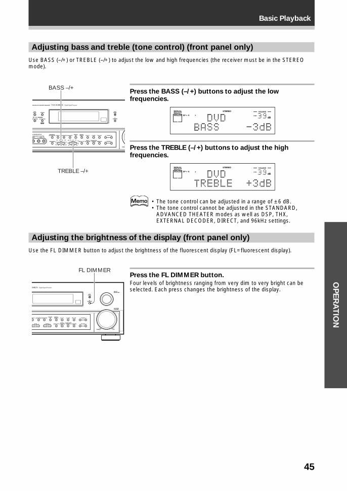
45
Basic PlaybackO
PE
RA
TIO
N
Adjusting the brightness of the display (front panel only)
Use the FL DIMMER button to adjust the brightness of the fluorescent display (FL=fluorescent display).
Press the FL DIMMER button.
Four levels of brightness ranging from very dim to very bright can beselected. Each press changes the brightness of the display.
Adjusting bass and treble (tone control) (front panel only)
Use BASS (–/+) or TREBLE (–/+) to adjust the low and high frequencies (the receiver must be in the STEREOmode).
Press the BASS (–/+) buttons to adjust the lowfrequencies.
dB
STEREOSIGNALSELECTANALOG SP A
VOLUME
Press the TREBLE (–/+) buttons to adjust the highfrequencies.
dB
STEREOSIGNALSELECTANALOG SP A
VOLUME
• The tone control can be adjusted in a range of ± 6 dB.• The tone control cannot be adjusted in the STANDARD,
ADVANCED THEATER modes as well as DSP, THX,EXTERNAL DECODER, DIRECT, and 96kHz settings.
DSPMODE
EONMODE
FLDIMMER
DEO MULTI-CHANNEL RECEIVER
STEREO
L POWER OUTPUT
IDEO
EXTERNALDECODER IN
TAPE 2MONITOR
DIRECT LOUDNESS MIDNIGHTDIGITAL
NR CLASS FM/AM
MEMORYCHARACTER/SEARCHINPUT ATTSPEAKERS
– TUNING +
– STATION +– TREBLE +– BASS +
L AUDIO RVIDEO INPUT
ADVANCED STANDARD
/DTS
MPEG
DOWN
RF ATTSIGNALSELECT
BASS –/+
TREBLE –/+
EONMODE
INPUTSELECTOR
MASTERVOLUME
FLDIMMER
TAPE 2MONITOR
RECT LOUDNESS MIDNIGHTDIGITAL
NR CLASS FM/AM
MEMORYCHARACTER/SEARCHINPUT ATT
– TUNING +
– STATION +– TREBLE +– BASS +
DOWN UP
RF ATTSIGNALSELECT
FL DIMMER
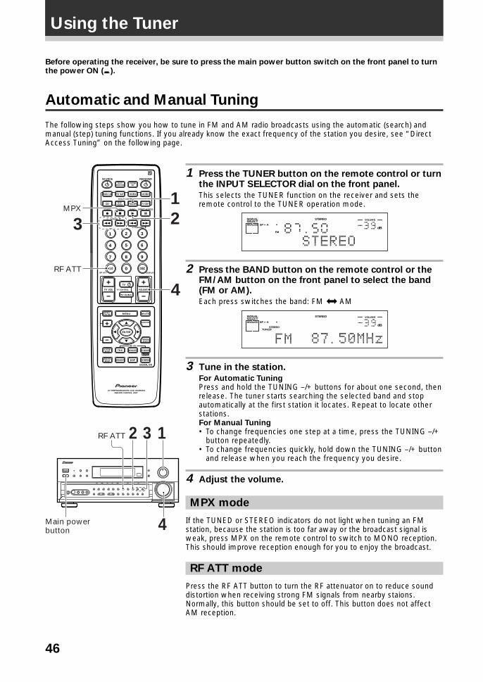
46
Before operating the receiver, be sure to press the main power button switch on the front panel to turnthe power ON (_).
Automatic and Manual Tuning
The following steps show you how to tune in FM and AM radio broadcasts using the automatic (search) andmanual (step) tuning functions. If you already know the exact frequency of the station you desire, see “DirectAccess Tuning” on the following page.
1 Press the TUNER button on the remote control or turnthe INPUT SELECTOR dial on the front panel.
This selects the TUNER function on the receiver and sets theremote control to the TUNER operation mode.
dB
STEREOSIGNALSELECTANALOG SP A
FM
VOLUME
2 Press the BAND button on the remote control or theFM/AM button on the front panel to select the band(FM or AM).
Each press switches the band: FM j AM
dB
STEREOSIGNALSELECTANALOG SP A
STEREOTUNED
VOLUME
3 Tune in the station.
For Automatic TuningPress and hold the TUNING –/+ buttons for about one second, thenrelease. The tuner starts searching the selected band and stopautomatically at the first station it locates. Repeat to locate otherstations.For Manual Tuning• To change frequencies one step at a time, press the TUNING –/+
button repeatedly.• To change frequencies quickly, hold down the TUNING –/+ button
and release when you reach the frequency you desire.
4 Adjust the volume.
MPX mode
If the TUNED or STEREO indicators do not light when tuning an FMstation, because the station is too far away or the broadcast signal isweak, press MPX on the remote control to switch to MONO reception.This should improve reception enough for you to enjoy the broadcast.
RF ATT mode
Press the RF ATT button to turn the RF attenuator on to reduce sounddistortion when receiving strong FM signals from nearby staions.Normally, this button should be set to off. This button does not affectAM reception.
THX
S0URCE
DVD/LD TV/SAT VCR1 VCR2
CD
TV VOL
TV FUNC
MENU
ENTER
STEREO
DIGITAL NR
MIDNIGHT
ADVANCED STANDARD
DSP
MUTE
TV
VOLUME
MD/TAPE1 TUNER TV CONT
RECEIVER
MULTIOPERATION
CLASS MPX
MULTI CONTROL
DIRECT ACCESS
STATION
CHANNEL
TUNING
DISPLAYRF ATT
TV CONTROL
FUNCTION
SIGNALSELECT
EFFECT/CH SEL
2/dts
AV PREPROGRAMMED AND LEARNINGREMOTE CONTROL UNIT
REMOTESETUP
SYSTEMSETUP
BAND
SYSTEMOFF
1 2 3
4 5 6
7
+10
8 9
0 DISC
Î
¶ 7 3 8
1 ¡ 4 ¢ +- +-
+-
MPEG
1
3MPX
RF ATT
2
4
3 12
4
RF ATT
Main power button
Using the Tuner
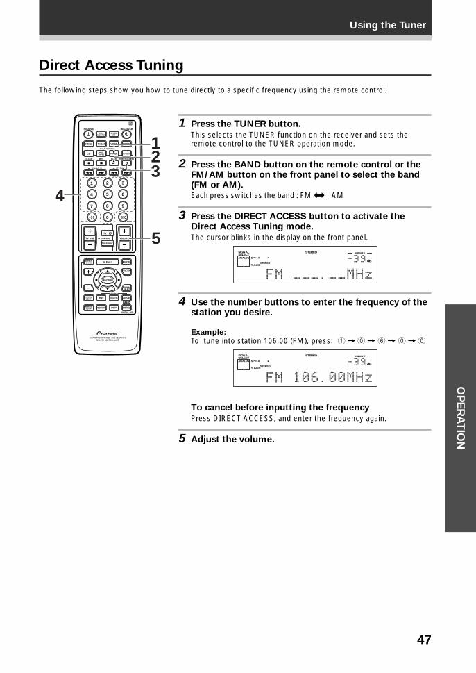
47
Using the TunerO
PE
RA
TIO
N
Direct Access Tuning
The following steps show you how to tune directly to a specific frequency using the remote control.
1 Press the TUNER button.
This selects the TUNER function on the receiver and sets theremote control to the TUNER operation mode.
2 Press the BAND button on the remote control or theFM/AM button on the front panel to select the band(FM or AM).Each press switches the band : FM j AM
3 Press the DIRECT ACCESS button to activate theDirect Access Tuning mode.
The cursor blinks in the display on the front panel.
dB
STEREOSIGNALSELECTANALOG SP A
STEREOTUNED
VOLUME
4 Use the number buttons to enter the frequency of thestation you desire.
Example:To tune into station 106.00 (FM), press: 1 = ` = 6 = ` = `
dB
STEREOSIGNALSELECTANALOG SP A
STEREOTUNED
VOLUME
To cancel before inputting the frequency
Press DIRECT ACCESS, and enter the frequency again.
5 Adjust the volume.
S0URCE
DVD/LD TV/SAT VCR1 VCR2
CD
TV VOL
TV FUNC
MENU
ENTER
STEREO
DIGITAL NR
MIDNIGHT
ADVANCED STANDARD
DSP
THX
MUTE
TV
VOLUME
MD/TAPE1 TUNER TV CONT
RECEIVER
MULTIOPERATION
CLASS MPX
MULTI CONTROL
DIRECT ACCESS
STATION
CHANNEL
TUNING
DISPLAYRF ATT
TV CONTROL
FUNCTION
SIGNALSELECT
EFFECT/CH SEL
2/dts
AV PREPROGRAMMED AND LEARNINGREMOTE CONTROL UNIT
REMOTESETUP
SYSTEMSETUP
BAND
SYSTEMOFF
1 2 3
4 5 6
7
+10
8 9
0 DISC
Î
¶ 7 3 8
1 ¡ 4 ¢ +- +-
+-
MPEG
1
4
23
5
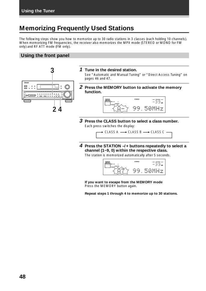
48
Using the Tuner
Memorizing Frequently Used Stations
The following steps show you how to memorize up to 30 radio stations in 3 classes (each holding 10 channels).When memorizing FM frequencies, the receiver also memorizes the MPX mode (STEREO or MONO for FMonly) and RF ATT mode (FM only).
Using the front panel
1 Tune in the desired station.
See “Automatic and Manual Tuning” or “Direct Access Tuning” onpages 46 and 47.
2 Press the MEMORY button to activate the memoryfunction.
dB
STEREOSIGNALSELECTANALOG SP A
STEREOTUNED
VOLUME
3 Press the CLASS button to select a class number.
Each press switches the display:
CLASS A CLASS B CLASS C
4 Press the STATION –/+ buttons repeatedly to select achannel (1~9, 0) within the respective class.
The station is memorized automatically after 5 seconds.
dB
STEREOSIGNALSELECTANALOG SP A
STEREOTUNED
VOLUME
If you want to escape from the MEMORY modePress the MEMORY button again.
Repeat steps 1 through 4 to memorize up to 30 stations.
3
42
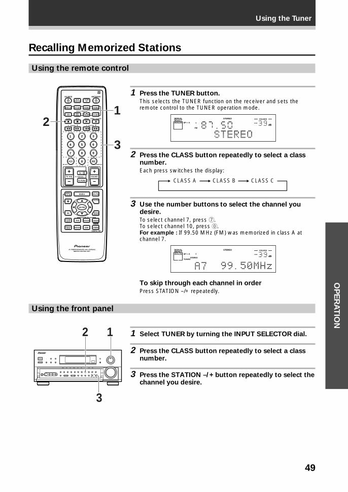
49
Using the TunerO
PE
RA
TIO
N
Recalling Memorized Stations
Using the remote control
1 Press the TUNER button.
This selects the TUNER function on the receiver and sets theremote control to the TUNER operation mode.
dB
STEREOSIGNALSELECTANALOG SP A
FM
VOLUME
2 Press the CLASS button repeatedly to select a classnumber.
Each press switches the display:
CLASS A CLASS B CLASS C
3 Use the number buttons to select the channel youdesire.
To select channel 7, press 7.To select channel 10, press `.For example : If 99.50 MHz (FM) was memorized in class A atchannel 7.
dB
STEREOSIGNALSELECTANALOG SP A
STEREOTUNED
VOLUME
To skip through each channel in order
Press STATION –/+ repeatedly.
Using the front panel
1 Select TUNER by turning the INPUT SELECTOR dial.
2 Press the CLASS button repeatedly to select a classnumber.
3 Press the STATION –/+ button repeatedly to select thechannel you desire.
S0URCE
DVD/LD TV/SAT VCR1 VCR2
CD
TV VOL
TV FUNC
MENU
ENTER
STEREO
DIGITAL NR
MIDNIGHT
ADVANCED STANDARD
DSP
THX
MUTE
TV
VOLUME
MD/TAPE1 TUNER TV CONT
RECEIVER
MULTIOPERATION
CLASS MPX
MULTI CONTROL
DIRECT ACCESS
STATION
CHANNEL
TUNING
DISPLAYRF ATT
TV CONTROL
FUNCTION
SIGNALSELECT
EFFECT/CH SEL
2/dts
AV PREPROGRAMMED AND LEARNINGREMOTE CONTROL UNIT
REMOTESETUP
SYSTEMSETUP
BAND
SYSTEMOFF
1 2 3
4 5 6
7
+10
8 9
0 DISC
Î
¶ 7 3 8
1 ¡ 4 ¢ +- +-
+-
MPEG
3
21
2
3
1
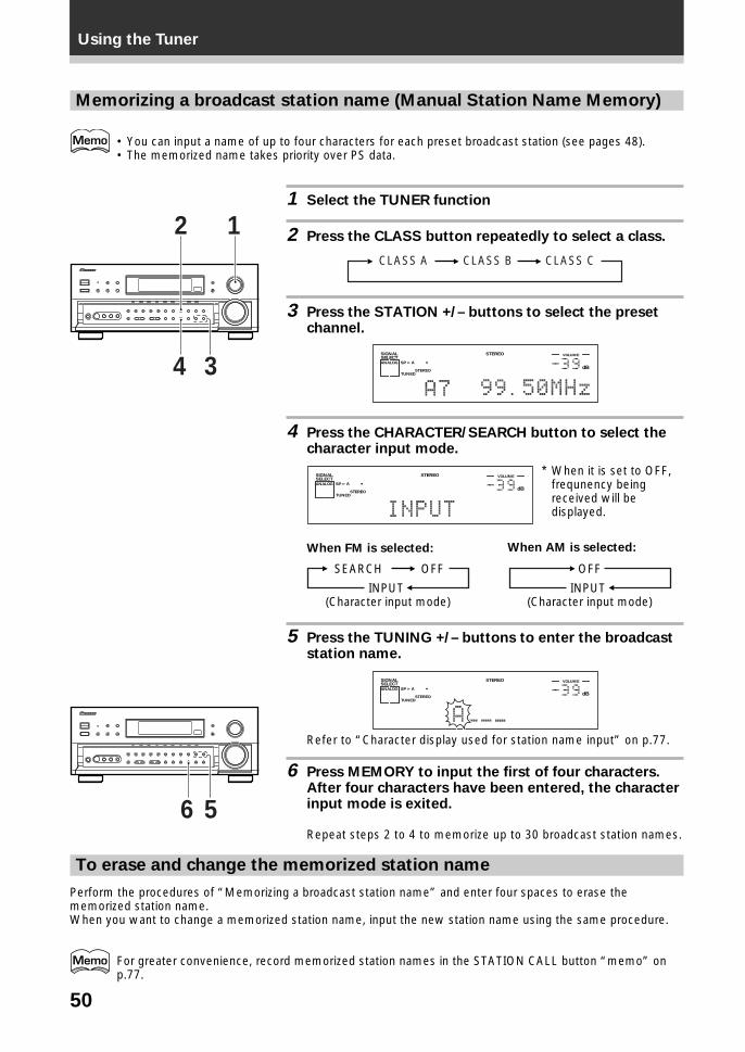
50
Using the Tuner
Memorizing a broadcast station name (Manual Station Name Memory)
• You can input a name of up to four characters for each preset broadcast station (see pages 48).• The memorized name takes priority over PS data.
1 Select the TUNER function
2 Press the CLASS button repeatedly to select a class.
CLASS A CLASS B CLASS C
3 Press the STATION +/– buttons to select the presetchannel.
dB
STEREOSIGNALSELECTANALOG SP A
STEREOTUNED
VOLUME
4 Press the CHARACTER/SEARCH button to select thecharacter input mode.
dB
STEREOSIGNALSELECTANALOG SP A
STEREOTUNED
VOLUME
When FM is selected:
INPUT (Character input mode)
OFFSEARCH
5 Press the TUNING +/– buttons to enter the broadcaststation name.
dB
STEREOSIGNALSELECTANALOG SP A
STEREOTUNED
VOLUME
Refer to “Character display used for station name input” on p.77.
6 Press MEMORY to input the first of four characters.After four characters have been entered, the characterinput mode is exited.
Repeat steps 2 to 4 to memorize up to 30 broadcast station names.
2
34
1
* When it is set to OFF,frequnency beingreceived will bedisplayed.
56
To erase and change the memorized station name
Perform the procedures of “Memorizing a broadcast station name” and enter four spaces to erase thememorized station name.When you want to change a memorized station name, input the new station name using the same procedure.
For greater convenience, record memorized station names in the STATION CALL button “memo” onp.77.
When AM is selected:
INPUT (Character input mode)
OFF
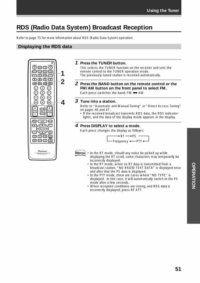
51
Using the TunerO
PE
RA
TIO
N
RDS (Radio Data System) Broadcast Reception
Refer to page 75 for more information about RDS (Radio Data Sytem) operation.
Displaying the RDS data
1 Press the TUNER button.
This selects the TUNER function on the receiver and sets theremote control to the TUNER operation mode.The previously tuned station is received automatically.
2 Press the BAND button on the remote control or theFM/AM button on the front panel to select FM.
Each press switches the band: FM j AM
3 Tune into a station.
Refer to “Automatic and Manual Tuning” or “Direct Access Tuning”on pages 46 and 47.• If the received broadcast transmits RDS data, the RDS indicator
lights, and the data of the display mode appears in the display.
4 Press DISPLAY to select a mode.
Each press changes the display as follows:
Frequency
PSRT
PTY
• In the RT mode, should any noise be picked up whiledisplaying the RT scroll, some characters may temporarily beincorrectly displayed.
• In the RT mode, when no RT data is transmitted from abroadcast station, “NO RADIO TEXT DATA” is displayed onceand after that the PS data is displayed.
• In the PTY mode, there are cases where “NO TYPE” isdisplayed. In this case, it will automatically switch to the PSmode after a few seconds.
• When reception conditions are strong, and RDS data isincorrectly displayed, press RF ATT.
THX
S0URCE
DVD/LD TV/SAT VCR1 VCR2
CD
TV VOL
TV FUNC
MENU
ENTER
STEREO
DIGITAL NR
MIDNIGHT
ADVANCED STANDARD
DSP
MUTE
TV
VOLUME
MD/TAPE1 TUNER TV CONT
RECEIVER
MULTIOPERATION
CLASS MPX
MULTI CONTROL
DIRECT ACCESS
STATION
CHANNEL
TUNING
DISPLAYRF ATT
TV CONTROL
FUNCTION
SIGNALSELECT
EFFECT/CH SEL
2/dts
AV PREPROGRAMMED AND LEARNINGREMOTE CONTROL UNIT
REMOTESETUP
SYSTEMSETUP
BAND
SYSTEMOFF
1 2 3
4 5 6
7
+10
8 9
0 DISC
Î
¶ 7 3 8
1 ¡ 4 ¢ +- +-
+-
MPEG
1
2
4
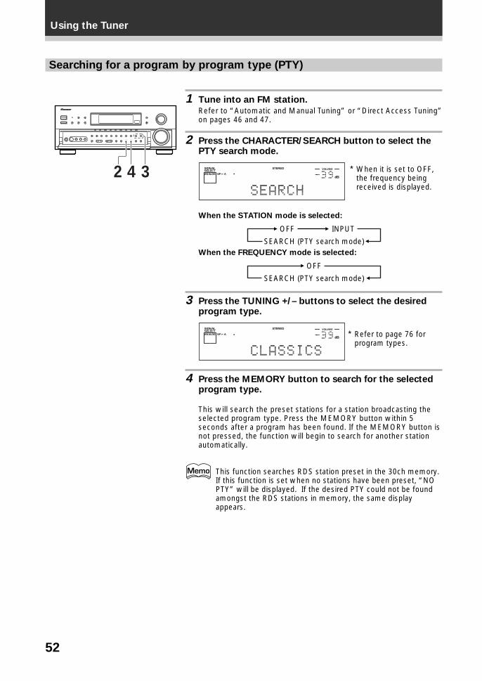
52
Using the Tuner
Searching for a program by program type (PTY)
1 Tune into an FM station.
Refer to “Automatic and Manual Tuning” or “Direct Access Tuning”on pages 46 and 47.
2 Press the CHARACTER/SEARCH button to select thePTY search mode.
dB
STEREOSIGNALSELECTANALOG SP A
VOLUME
When the STATION mode is selected:
SEARCH (PTY search mode)
INPUTOFF
When the FREQUENCY mode is selected:
SEARCH (PTY search mode)
OFF
3 Press the TUNING +/– buttons to select the desiredprogram type.
dB
STEREOSIGNALSELECTANALOG SP A
VOLUME
4 Press the MEMORY button to search for the selectedprogram type.
This will search the preset stations for a station broadcasting theselected program type. Press the MEMORY button within 5seconds after a program has been found. If the MEMORY button isnot pressed, the function will begin to search for another stationautomatically.
This function searches RDS station preset in the 30ch memory.If this function is set when no stations have been preset, “NOPTY” will be displayed. If the desired PTY could not be foundamongst the RDS stations in memory, the same displayappears.
342 * When it is set to OFF,the frequency beingreceived is displayed.
* Refer to page 76 forprogram types.
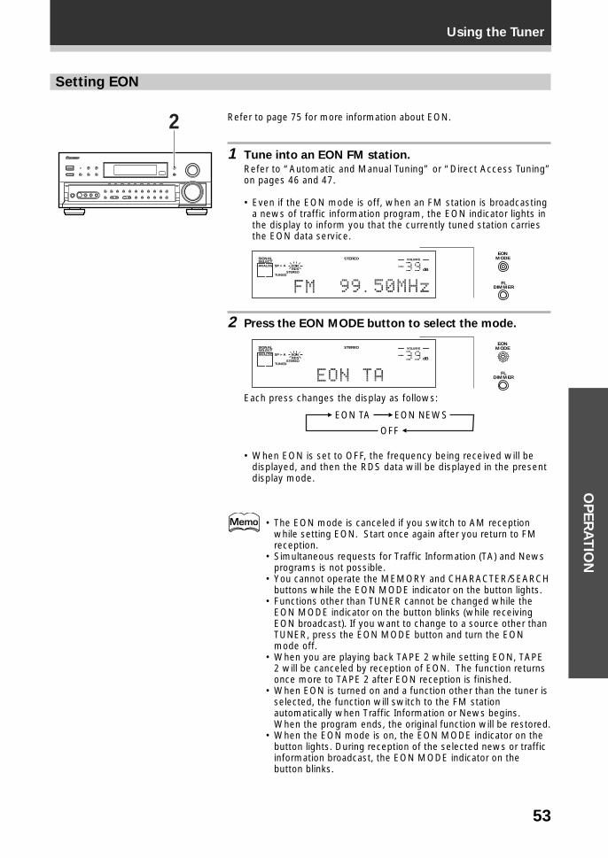
53
Using the TunerO
PE
RA
TIO
N
Setting EON
Refer to page 75 for more information about EON.
1 Tune into an EON FM station.
Refer to “Automatic and Manual Tuning” or “Direct Access Tuning”on pages 46 and 47.
• Even if the EON mode is off, when an FM station is broadcastinga news of traffic information program, the EON indicator lights inthe display to inform you that the currently tuned station carriesthe EON data service.
dB
STEREOSIGNALSELECTANALOG SP A EON
RDSSTEREO
TUNED
VOLUME
EONMODE
FLDIMMER
2 Press the EON MODE button to select the mode.
dB
STEREOSIGNALSELECTANALOG SP A EON
RDSSTEREO
TUNED
VOLUMEEON
MODE
FLDIMMER
Each press changes the display as follows:
OFF
EON NEWSEON TA
• When EON is set to OFF, the frequency being received will bedisplayed, and then the RDS data will be displayed in the presentdisplay mode.
• The EON mode is canceled if you switch to AM receptionwhile setting EON. Start once again after you return to FMreception.
• Simultaneous requests for Traffic Information (TA) and Newsprograms is not possible.
• You cannot operate the MEMORY and CHARACTER/SEARCHbuttons while the EON MODE indicator on the button lights.
• Functions other than TUNER cannot be changed while theEON MODE indicator on the button blinks (while receivingEON broadcast). If you want to change to a source other thanTUNER, press the EON MODE button and turn the EONmode off.
• When you are playing back TAPE 2 while setting EON, TAPE2 will be canceled by reception of EON. The function returnsonce more to TAPE 2 after EON reception is finished.
• When EON is turned on and a function other than the tuner isselected, the function will switch to the FM stationautomatically when Traffic Information or News begins.When the program ends, the original function will be restored.
• When the EON mode is on, the EON MODE indicator on thebutton lights. During reception of the selected news or trafficinformation broadcast, the EON MODE indicator on thebutton blinks.
2
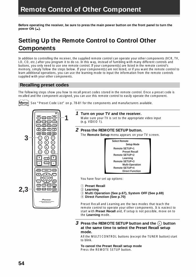
54
Before operating the receiver, be sure to press the main power button on the front panel to turn thepower ON (_).
Setting Up the Remote Control to Control Other
Components
In addition to controlling the receiver, the supplied remote control can operate your other components (VCR, TV,LD, CD, etc.) after you program it to do so. In this way, instead of fumbling with many different controls andbuttons, you only need to use one remote control. If your component(s) are listed in the remote control’smemory, simply follow the steps below. If your component(s) are not listed, or if you want the remote control tolearn additional operations, you can use the learning mode to input the information from the remote controlssupplied with your other components.
Recalling preset codes
The following steps show you how to recall preset codes stored in the remote control. Once a preset code isrecalled and the component assigned, you can use this remote control to easily operate the component.
See “Preset Code List” on p. 78-81 for the components and manufacturers available.
1 Turn on your TV and the receiver.Make sure your TV is set to the appropriate video input(e.g. VIDEO 1).
2 Press the REMOTE SETUP button.
The Remote Setup menu appears on your TV screen.
Select Remote Setup Mode
Remote SETUP+1 Preset RecallRemote SETUP+2 LearningRemote SETUP+3 Multi-OperationRemote SETUP+4 Direct Function
You have four set up options:
1 Preset Recall2 Learning3 Multi Operation (See p.67), System OFF (See p.69)4 Direct Function (See p.70)
Preset Recall and Learning are the two modes that teach theremote control to operate your other components. It is easiest tostart with Preset Recall and, if setup is not possible, move on tothe Learning mode.
3 Press the REMOTE SETUP button and the 1 button
at the same time to select the Preset Recall setupmode.
All the MULTI CONTROL buttons (except the TUNER button) startto blink.
To cancel the Preset Recall setup modePress the REMOTE SETUP button.
S0URCE
DVD/LD TV/SAT VCR1 VCR2
CD
TV VOL
TV FUNC
MENU
ENTER
STEREO
DIGITAL NR
MIDNIGHT
ADVANCED STANDARD
DSP
THX
MUTE
TV
VOLUME
MD/TAPE1 TUNER TV CONT
RECEIVER
MULTIOPERATION
CLASS MPX
MULTI CONTROL
DIRECT ACCESS
STATION
CHANNEL
TUNING
DISPLAYRF ATT
TV CONTROL
FUNCTION
SIGNALSELECT
EFFECT/CH SEL
2/dts
AV PREPROGRAMMED AND LEARNINGREMOTE CONTROL UNIT
REMOTESETUP
SYSTEMSETUP
BAND
SYSTEMOFF
1 2 3
4 5 6
7
+10
8 9
0 DISC
Î
¶ 7 3 8
1 ¡ 4 ¢ +- +-
+-
MPEG
3
2,3
1
Remote Control of Other Component
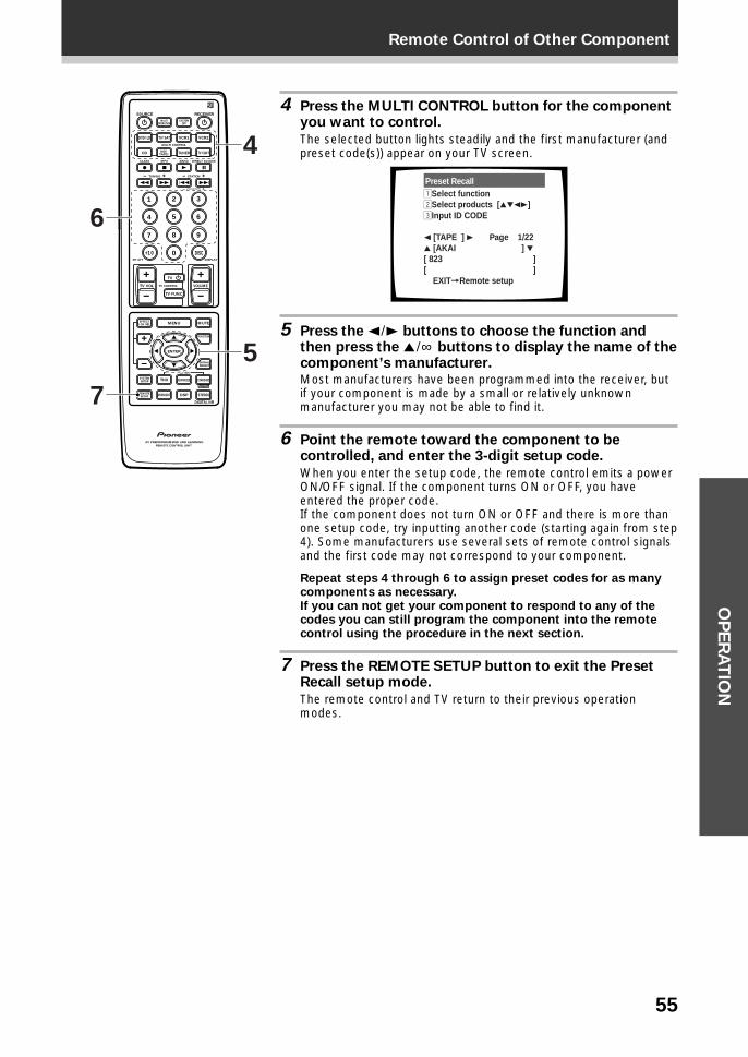
55
Remote Control of Other ComponentO
PE
RA
TIO
N
4 Press the MULTI CONTROL button for the componentyou want to control.
The selected button lights steadily and the first manufacturer (andpreset code(s)) appear on your TV screen.
Preset Recall1Select function2Select products [5∞23]3Input ID CODE
2 [TAPE ] 3 Page 1/22 5 [AKAI ] ∞[ 823 ][ ] EXIT=Remote setup
5 Press the 2¥3 buttons to choose the function andthen press the 5¥∞ buttons to display the name of thecomponent’s manufacturer.Most manufacturers have been programmed into the receiver, butif your component is made by a small or relatively unknownmanufacturer you may not be able to find it.
6 Point the remote toward the component to becontrolled, and enter the 3-digit setup code.
When you enter the setup code, the remote control emits a powerON/OFF signal. If the component turns ON or OFF, you haveentered the proper code.If the component does not turn ON or OFF and there is more thanone setup code, try inputting another code (starting again from step4). Some manufacturers use several sets of remote control signalsand the first code may not correspond to your component.
Repeat steps 4 through 6 to assign preset codes for as manycomponents as necessary.If you can not get your component to respond to any of thecodes you can still program the component into the remotecontrol using the procedure in the next section.
7 Press the REMOTE SETUP button to exit the PresetRecall setup mode.
The remote control and TV return to their previous operationmodes.
S0URCE
DVD/LD TV/SAT VCR1 VCR2
CD
TV VOL
TV FUNC
MENU
ENTER
STEREO
DIGITAL NR
MIDNIGHT
ADVANCED STANDARD
DSP
THX
MUTE
TV
VOLUME
MD/TAPE1 TUNER TV CONT
RECEIVER
MULTIOPERATION
CLASS MPX
MULTI CONTROL
DIRECT ACCESS
STATION
CHANNEL
TUNING
DISPLAYRF ATT
TV CONTROL
FUNCTION
SIGNALSELECT
EFFECT/CH SEL
2/dts
AV PREPROGRAMMED AND LEARNINGREMOTE CONTROL UNIT
REMOTESETUP
SYSTEMSETUP
BAND
SYSTEMOFF
1 2 3
4 5 6
7
+10
8 9
0 DISC
Î
¶ 7 3 8
1 ¡ 4 ¢ +- +-
+-
MPEG
6
7
4
5
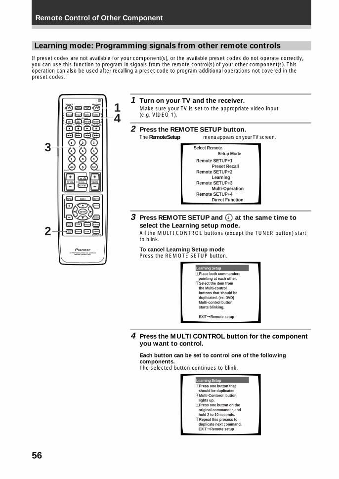
56
Remote Control of Other Component
Learning mode: Programming signals from other remote controls
If preset codes are not available for your component(s), or the available preset codes do not operate correctly,you can use this function to program in signals from the remote control(s) of your other component(s). Thisoperation can also be used after recalling a preset code to program additional operations not covered in thepreset codes.
1 Turn on your TV and the receiver.
Make sure your TV is set to the appropriate video input(e.g. VIDEO 1).
2 Press the REMOTE SETUP button.The Remote Setup menu appears on your TV screen.
Select Remote Setup Mode
Remote SETUP+1 Preset RecallRemote SETUP+2 LearningRemote SETUP+3 Multi-OperationRemote SETUP+4 Direct Function
3 Press REMOTE SETUP and 2 at the same time to
select the Learning setup mode.All the MULTI CONTROL buttons (except the TUNER button) startto blink.
To cancel Learning Setup modePress the REMOTE SETUP button.
Learning Setup1Place both commanders pointing at each other.2Select the item from
the Multi-control buttons that should be duplicated. (ex. DVD)Multi-control button
starts blinking.
EXIT=Remote setup
4 Press the MULTI CONTROL button for the componentyou want to control.
Each button can be set to control one of the followingcomponents.The selected button continues to blink.
Learning Setup3Press one button that should be duplicated.4Multi-Contorol button lights up.5Press one button on the original commander, and hold 2 to 10 seconds. 6Repeat this process to duplicate next command. EXIT=Remote setup
S0URCE
DVD/LD TV/SAT VCR1 VCR2
CD
TV VOL
TV FUNC
MENU
ENTER
STEREO
DIGITAL NR
MIDNIGHT
ADVANCED STANDARD
DSP
THX
MUTE
TV
VOLUME
MD/TAPE1 TUNER TV CONT
RECEIVER
MULTIOPERATION
CLASS MPX
MULTI CONTROL
DIRECT ACCESS
STATION
CHANNEL
TUNING
DISPLAYRF ATT
TV CONTROL
FUNCTION
SIGNALSELECT
EFFECT/CH SEL
2/dts
AV PREPROGRAMMED AND LEARNINGREMOTE CONTROL UNIT
REMOTESETUP
SYSTEMSETUP
BAND
SYSTEMOFF
1 2 3
4 5 6
7
+10
8 9
0 DISC
Î
¶ 7 3 8
1 ¡ 4 ¢ +- +-
+-
MPEG
3
2
41
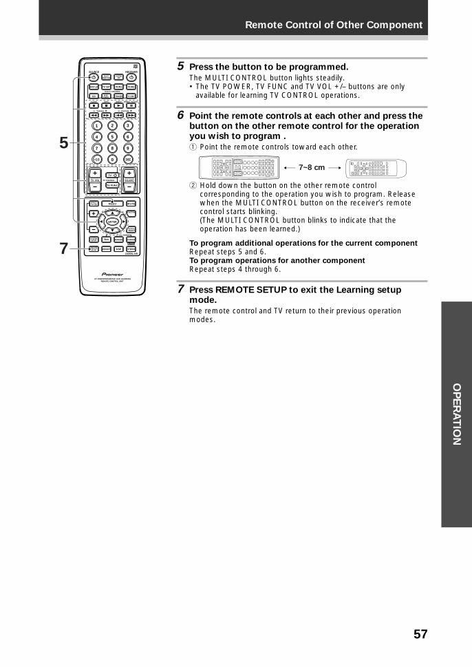
57
Remote Control of Other ComponentO
PE
RA
TIO
N
5 Press the button to be programmed.
The MULTI CONTROL button lights steadily.• The TV POWER, TV FUNC and TV VOL +/– buttons are only
available for learning TV CONTROL operations.
6 Point the remote controls at each other and press thebutton on the other remote control for the operationyou wish to program .
1 Point the remote controls toward each other.
7~8 cm
2 Hold down the button on the other remote controlcorresponding to the operation you wish to program. Releasewhen the MULTI CONTROL button on the receiver’s remotecontrol starts blinking.(The MULTI CONTROL button blinks to indicate that theoperation has been learned.)
To program additional operations for the current componentRepeat steps 5 and 6.To program operations for another componentRepeat steps 4 through 6.
7 Press REMOTE SETUP to exit the Learning setupmode.
The remote control and TV return to their previous operationmodes.
S0URCE
DVD/LD TV/SAT VCR1 VCR2
CD
TV VOL
TV FUNC
MENU
ENTER
STEREO
DIGITAL NR
MIDNIGHT
ADVANCED STANDARD
DSP
THX
MUTE
TV
VOLUME
MD/TAPE1 TUNER TV CONT
RECEIVER
MULTIOPERATION
CLASS MPX
MULTI CONTROL
DIRECT ACCESS
STATION
CHANNEL
TUNING
DISPLAYRF ATT
TV CONTROL
FUNCTION
SIGNALSELECT
EFFECT/CH SEL
2/dts
AV PREPROGRAMMED AND LEARNINGREMOTE CONTROL UNIT
REMOTESETUP
SYSTEMSETUP
BAND
SYSTEMOFF
1 2 3
4 5 6
7
+10
8 9
0 DISC
Î
¶ 7 3 8
1 ¡ 4 ¢ +- +-
+-
MPEG
5
7
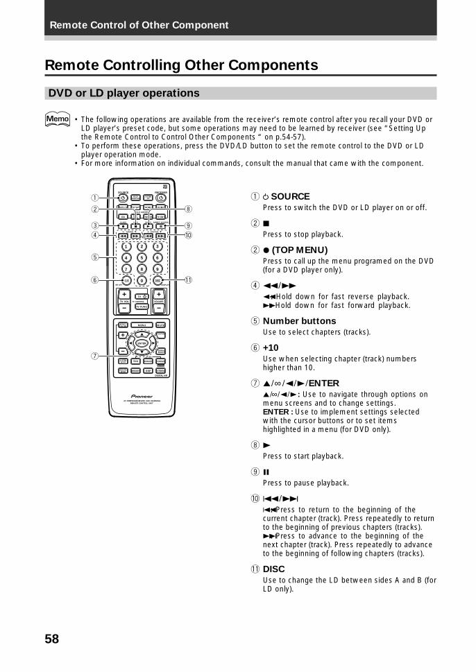
58
Remote Control of Other Component
Remote Controlling Other Components
DVD or LD player operations
• The following operations are available from the receiver’s remote control after you recall your DVD orLD player’s preset code, but some operations may need to be learned by receiver (see “Setting Upthe Remote Control to Control Other Components “ on p.54-57).
• To perform these operations, press the DVD/LD button to set the remote control to the DVD or LDplayer operation mode.
• For more information on individual commands, consult the manual that came with the component.
1 SOURCE
Press to switch the DVD or LD player on or off.
2 7Press to stop playback.
2 ¶ (TOP MENU)
Press to call up the menu programed on the DVD(for a DVD player only).
4 1¥¡1 : Hold down for fast reverse playback.¡ : Hold down for fast forward playback.
5 Number buttons
Use to select chapters (tracks).
6 +10
Use when selecting chapter (track) numbershigher than 10.
7 5¥∞¥2¥3¥ENTER
5¥∞¥2¥3 : Use to navigate through options onmenu screens and to change settings.ENTER : Use to implement settings selectedwith the cursor buttons or to set itemshighlighted in a menu (for DVD only).
8 3Press to start playback.
9 8Press to pause playback.
0 4¥¢4 : Press to return to the beginning of thecurrent chapter (track). Press repeatedly to returnto the beginning of previous chapters (tracks).¢ : Press to advance to the beginning of thenext chapter (track). Press repeatedly to advanceto the beginning of following chapters (tracks).
- DISC
Use to change the LD between sides A and B (forLD only).
S0URCE
DVD/LD TV/SAT VCR1 VCR2
CD
TV VOL
TV FUNC
MENU
ENTER
STEREO
DIGITAL NR
MIDNIGHT
ADVANCED STANDARD
DSP
THX
MUTE
TV
VOLUME
MD/TAPE1 TUNER TV CONT
RECEIVER
MULTIOPERATION
CLASS MPX
MULTI CONTROL
DIRECT ACCESS
STATION
CHANNEL
TUNING
DISPLAYRF ATT
TV CONTROL
FUNCTION
SIGNALSELECT
EFFECT/CH SEL
2/dts
AV PREPROGRAMMED AND LEARNINGREMOTE CONTROL UNIT
REMOTESETUP
SYSTEMSETUP
BAND
SYSTEMOFF
1 2 3
4 5 6
7
+10
8 9
0 DISC
Î
¶ 7 3 8
1 ¡ 4 ¢ +- +-
+-
MPEG
1
2
3
4
8
9
0
5
6
7
-
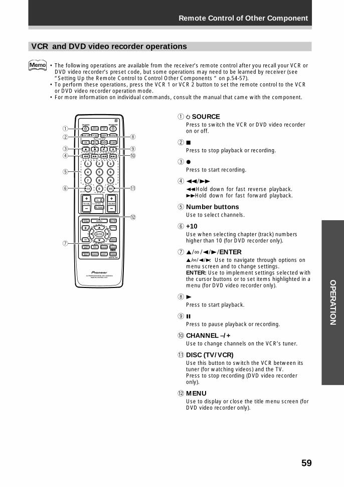
59
Remote Control of Other ComponentO
PE
RA
TIO
N
VCR and DVD video recorder operations
• The following operations are available from the receiver’s remote control after you recall your VCR orDVD video recorder’s preset code, but some operations may need to be learned by receiver (see“Setting Up the Remote Control to Control Other Components “ on p.54-57).
• To perform these operations, press the VCR 1 or VCR 2 button to set the remote control to the VCRor DVD video recorder operation mode.
• For more information on individual commands, consult the manual that came with the component.
1 SOURCE
Press to switch the VCR or DVD video recorderon or off.
2 7Press to stop playback or recording.
3 ¶Press to start recording.
4 1¥¡1 : Hold down for fast reverse playback.¡ : Hold down for fast forward playback.
5 Number buttons
Use to select channels.
6 +10
Use when selecting chapter (track) numbershigher than 10 (for DVD recorder only).
7 5¥∞ ¥2¥3¥ENTER
5¥∞¥2¥3: Use to navigate through options onmenu screen and to change settings.ENTER: Use to implement settings selected withthe cursor buttons or to set items highlighted in amenu (for DVD video recorder only).
8 3Press to start playback.
9 8Press to pause playback or recording.
0 CHANNEL –/+
Use to change channels on the VCR’s tuner.
- DISC (TV/VCR)
Use this button to switch the VCR between itstuner (for watching videos) and the TV.Press to stop recording (DVD video recorderonly).
= MENU
Use to display or close the title menu screen (forDVD video recorder only).
S0URCE
DVD/LD TV/SAT VCR1 VCR2
CD
TV VOL
TV FUNC
MENU
ENTER
STEREO
DIGITAL NR
MIDNIGHT
ADVANCED STANDARD
DSP
THX
MUTE
TV
VOLUME
MD/TAPE1 TUNER TV CONT
RECEIVER
MULTIOPERATION
CLASS MPX
MULTI CONTROL
DIRECT ACCESS
STATION
CHANNEL
TUNING
DISPLAYRF ATT
TV CONTROL
FUNCTION
SIGNALSELECT
EFFECT/CH SEL
2/dts
AV PREPROGRAMMED AND LEARNINGREMOTE CONTROL UNIT
REMOTESETUP
SYSTEMSETUP
BAND
SYSTEMOFF
1 2 3
4 5 6
7
+10
8 9
0 DISC
Î
¶ 7 3 8
1 ¡ 4 ¢ +- +-
+-
MPEG
1
2
3
4
8
9
0
5
6
7
-
=
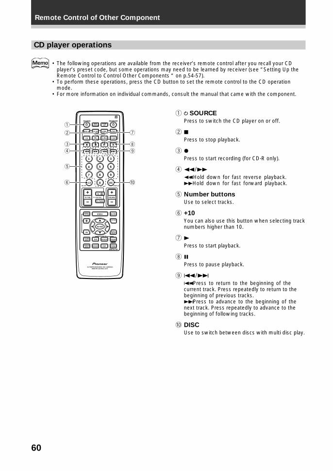
60
Remote Control of Other Component
CD player operations
• The following operations are available from the receiver’s remote control after you recall your CDplayer’s preset code, but some operations may need to be learned by receiver (see “Setting Up theRemote Control to Control Other Components “ on p.54-57).
• To perform these operations, press the CD button to set the remote control to the CD operationmode.
• For more information on individual commands, consult the manual that came with the component.
1 SOURCE
Press to switch the CD player on or off.
2 7Press to stop playback.
3 ¶Press to start recording (for CD-R only).
4 1¥¡1 : Hold down for fast reverse playback.¡ : Hold down for fast forward playback.
5 Number buttons
Use to select tracks.
6 +10
You can also use this button when selecting tracknumbers higher than 10.
7 3Press to start playback.
8 8Press to pause playback.
9 4¥¢4 : Press to return to the beginning of thecurrent track. Press repeatedly to return to thebeginning of previous tracks.¢ : Press to advance to the beginning of thenext track. Press repeatedly to advance to thebeginning of following tracks.
0 DISC
Use to switch between discs with multi disc play.
S0URCE
DVD/LD TV/SAT VCR1 VCR2
CD
TV VOL
TV FUNC
MENU
ENTER
STEREO
DIGITAL NR
MIDNIGHT
ADVANCED STANDARD
DSP
THX
MUTE
TV
VOLUME
MD/TAPE1 TUNER TV CONT
RECEIVER
MULTIOPERATION
CLASS MPX
MULTI CONTROL
DIRECT ACCESS
STATION
CHANNEL
TUNING
DISPLAYRF ATT
TV CONTROL
FUNCTION
SIGNALSELECT
EFFECT/CH SEL
2/dts
AV PREPROGRAMMED AND LEARNINGREMOTE CONTROL UNIT
REMOTESETUP
SYSTEMSETUP
BAND
SYSTEMOFF
1 2 3
4 5 6
7
+10
8 9
0 DISC
Î
¶ 7 3 8
1 ¡ 4 ¢ +- +-
+-
MPEG
1
2
3
4
7
8
9
5
6 0
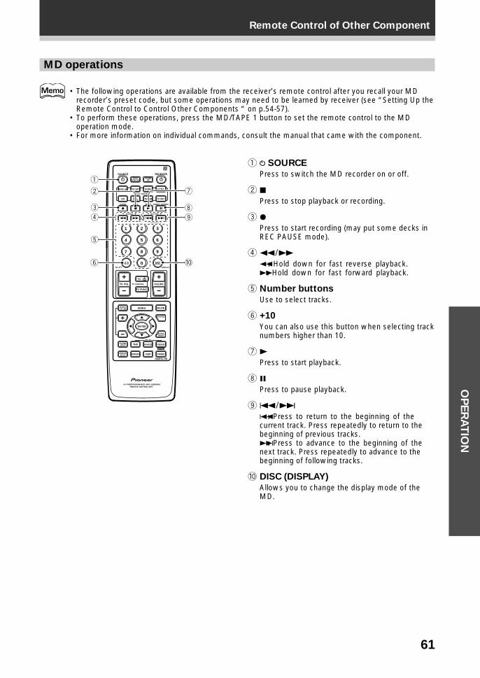
61
Remote Control of Other ComponentO
PE
RA
TIO
N
MD operations
• The following operations are available from the receiver’s remote control after you recall your MDrecorder’s preset code, but some operations may need to be learned by receiver (see “Setting Up theRemote Control to Control Other Components “ on p.54-57).
• To perform these operations, press the MD/TAPE 1 button to set the remote control to the MDoperation mode.
• For more information on individual commands, consult the manual that came with the component.
1 SOURCE
Press to switch the MD recorder on or off.
2 7Press to stop playback or recording.
3 ¶Press to start recording (may put some decks inREC PAUSE mode).
4 1¥¡1 : Hold down for fast reverse playback.¡ : Hold down for fast forward playback.
5 Number buttons
Use to select tracks.
6 +10
You can also use this button when selecting tracknumbers higher than 10.
7 3Press to start playback.
8 8Press to pause playback.
9 4¥¢4 : Press to return to the beginning of thecurrent track. Press repeatedly to return to thebeginning of previous tracks.¢ : Press to advance to the beginning of thenext track. Press repeatedly to advance to thebeginning of following tracks.
0 DISC (DISPLAY)
Allows you to change the display mode of theMD.
S0URCE
DVD/LD TV/SAT VCR1 VCR2
CD
TV VOL
TV FUNC
MENU
ENTER
STEREO
DIGITAL NR
MIDNIGHT
ADVANCED STANDARD
DSP
THX
MUTE
TV
VOLUME
MD/TAPE1 TUNER TV CONT
RECEIVER
MULTIOPERATION
CLASS MPX
MULTI CONTROL
DIRECT ACCESS
STATION
CHANNEL
TUNING
DISPLAYRF ATT
TV CONTROL
FUNCTION
SIGNALSELECT
EFFECT/CH SEL
2/dts
AV PREPROGRAMMED AND LEARNINGREMOTE CONTROL UNIT
REMOTESETUP
SYSTEMSETUP
BAND
SYSTEMOFF
1 2 3
4 5 6
7
+10
8 9
0 DISC
Î
¶ 7 3 8
1 ¡ 4 ¢ +- +-
+-
MPEG
1
2
3
4
7
8
9
5
6 0
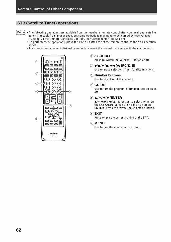
62
Remote Control of Other Component
STB (Satellite Tuner) operations
• The following operations are available from the receiver’s remote control after you recall your satellitetuner’s (or cable TV’s) preset code, but some operations may need to be learned by receiver (see“Setting Up the Remote Control to Control Other Components “ on p.54-57).
• To perform these operations, press the TV/SAT button to set the remote control to the SAT operationmode.
• For more information on individual commands, consult the manual that came with the component.
1 SOURCE
Press to switch the Satellite Tuner on or off.
2 ¶¥7¥3¥8¥1 (A/B/C/D/E)
Use to make selections from Satellite functions.
3 Number buttons
Use to select satellite channels.
4 GUIDE
Use to turn the program information screen on oroff.
5 5¥∞¥2¥3¥ENTER
5¥∞¥2¥3 : Press the button to select items onthe SAT GUIDE screen or SAT MENU screen.ENTER : Press to activate the selected function.
6 EXIT
Press to exit the current setting of the SAT.
7 MENU
Use to turn the main menu on or off.
S0URCE
DVD/LD TV/SAT VCR1 VCR2
CD
TV VOL
TV FUNC
MENU
ENTER
STEREO
DIGITAL NR
MIDNIGHT
ADVANCED STANDARD
DSP
THX
MUTE
TV
VOLUME
MD/TAPE1 TUNER TV CONT
RECEIVER
MULTIOPERATION
CLASS MPX
MULTI CONTROL
DIRECT ACCESS
STATION
CHANNEL
TUNING
DISPLAYRF ATT
TV CONTROL
FUNCTION
SIGNALSELECT
EFFECT/CH SEL
2/dts
AV PREPROGRAMMED AND LEARNINGREMOTE CONTROL UNIT
REMOTESETUP
SYSTEMSETUP
BAND
SYSTEMOFF
1 2 3
4 5 6
7
+10
8 9
0 DISC
Î
¶ 7 3 8
1 ¡ 4 ¢ +- +-
+-
MPEG
1
2
3
4
5
6
7
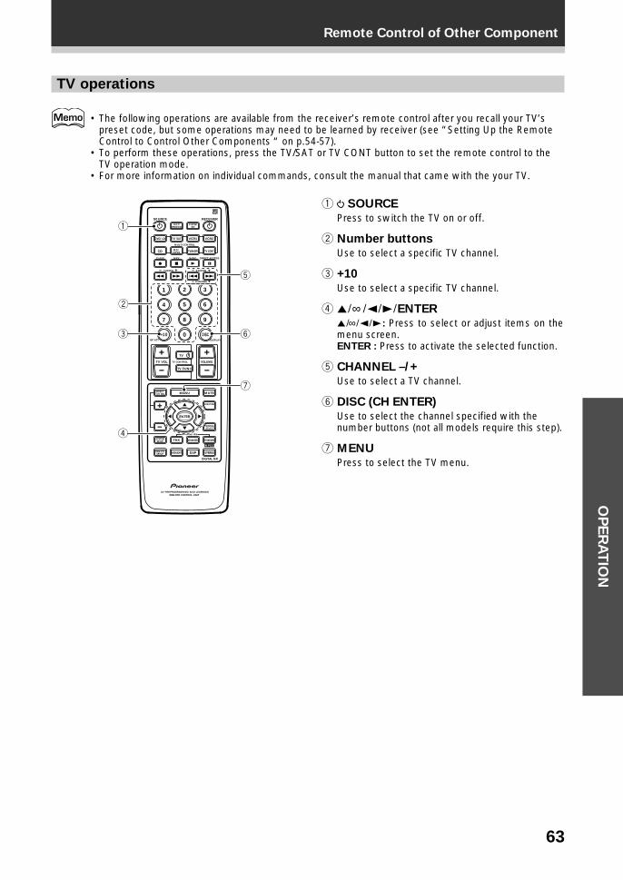
63
Remote Control of Other ComponentO
PE
RA
TIO
N
TV operations
• The following operations are available from the receiver’s remote control after you recall your TV’spreset code, but some operations may need to be learned by receiver (see “Setting Up the RemoteControl to Control Other Components “ on p.54-57).
• To perform these operations, press the TV/SAT or TV CONT button to set the remote control to theTV operation mode.
• For more information on individual commands, consult the manual that came with the your TV.
1 SOURCE
Press to switch the TV on or off.
2 Number buttons
Use to select a specific TV channel.
3 +10
Use to select a specific TV channel.
4 5¥∞ ¥2¥3¥ENTER
5¥∞¥2¥3 : Press to select or adjust items on themenu screen.ENTER : Press to activate the selected function.
5 CHANNEL –/+
Use to select a TV channel.
6 DISC (CH ENTER)
Use to select the channel specified with thenumber buttons (not all models require this step).
7 MENU
Press to select the TV menu.
S0URCE
DVD/LD TV/SAT VCR1 VCR2
CD
TV VOL
TV FUNC
MENU
ENTER
STEREO
DIGITAL NR
MIDNIGHT
ADVANCED STANDARD
DSP
THX
MUTE
TV
VOLUME
MD/TAPE1 TUNER TV CONT
RECEIVER
MULTIOPERATION
CLASS MPX
MULTI CONTROL
DIRECT ACCESS
STATION
CHANNEL
TUNING
DISPLAYRF ATT
TV CONTROL
FUNCTION
SIGNALSELECT
EFFECT/CH SEL
2/dts
AV PREPROGRAMMED AND LEARNINGREMOTE CONTROL UNIT
REMOTESETUP
SYSTEMSETUP
BAND
SYSTEMOFF
1 2 3
4 5 6
7
+10
8 9
0 DISC
Î
¶ 7 3 8
1 ¡ 4 ¢ +- +-
+-
MPEG
1
2
3
4
6
7
5
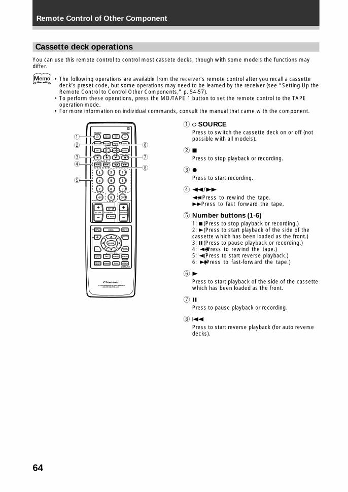
64
Remote Control of Other Component
Cassette deck operations
You can use this remote control to control most cassete decks, though with some models the functions maydiffer.
• The following operations are available from the receiver’s remote control after you recall a cassettedeck’s preset code, but some operations may need to be learned by the receiver (see “Setting Up theRemote Control to Control Other Components,” p. 54-57).
• To perform these operations, press the MD/TAPE 1 button to set the remote control to the TAPEoperation mode.
• For more information on individual commands, consult the manual that came with the component.
1 SOURCE
Press to switch the cassette deck on or off (notpossible with all models).
2 7Press to stop playback or recording.
3 ¶Press to start recording.
4 1¥¡1 : Press to rewind the tape.¡ : Press to fast forward the tape.
5 Number buttons (1-6)
1: 7 (Press to stop playback or recording.)2: 3 (Press to start playback of the side of thecassette which has been loaded as the front.)3: 8 (Press to pause playback or recording.)4: 1 (Press to rewind the tape.)5: 2 (Press to start reverse playback.)6: ¡ (Press to fast-forward the tape.)
6 3Press to start playback of the side of the cassettewhich has been loaded as the front.
7 8Press to pause playback or recording.
8 4Press to start reverse playback (for auto reversedecks).
S0URCE
DVD/LD TV/SAT VCR1 VCR2
CD
TV VOL
TV FUNC
MENU
ENTER
STEREO
DIGITAL NR
MIDNIGHT
ADVANCED STANDARD
DSP
THX
MUTE
TV
VOLUME
MD/TAPE1 TUNER TV CONT
RECEIVER
MULTIOPERATION
CLASS MPX
MULTI CONTROL
DIRECT ACCESS
STATION
CHANNEL
TUNING
DISPLAYRF ATT
TV CONTROL
FUNCTION
SIGNALSELECT
EFFECT/CH SEL
2/dts
AV PREPROGRAMMED AND LEARNINGREMOTE CONTROL UNIT
REMOTESETUP
SYSTEMSETUP
BAND
SYSTEMOFF
1 2 3
4 5 6
7
+10
8 9
0 DISC
Î
¶ 7 3 8
1 ¡ 4 ¢ +- +-
+-
MPEG
1
2
3
4
6
7
8
5
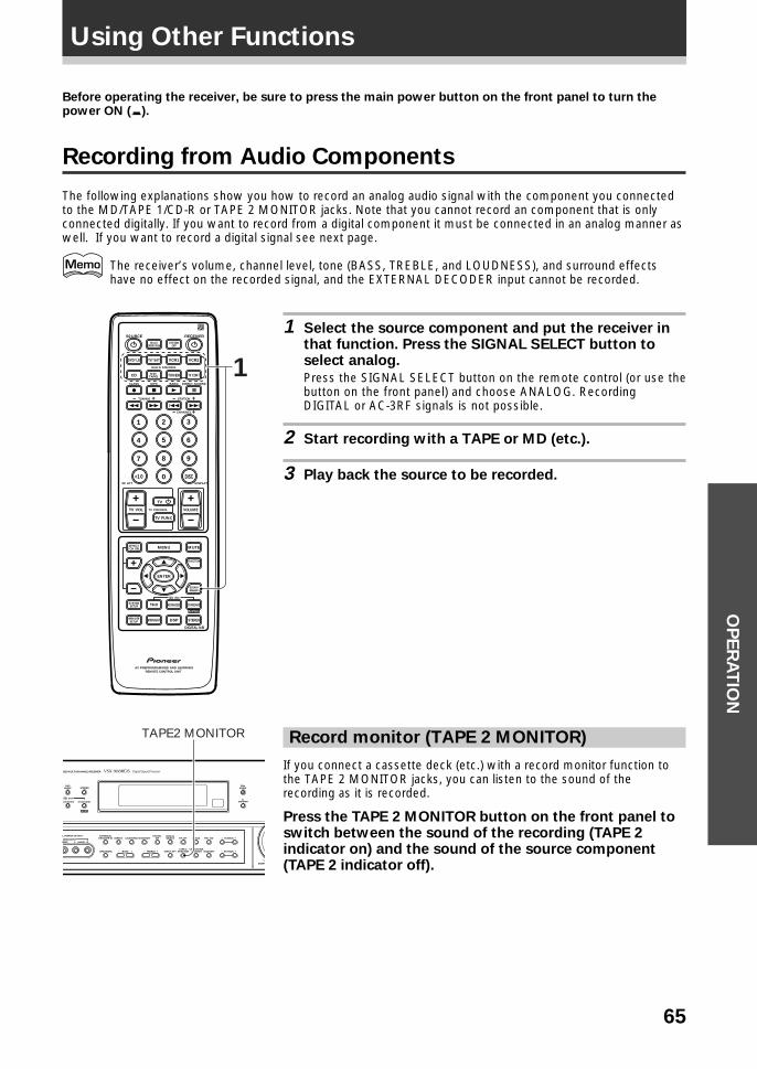
65
OP
ER
AT
ION
Before operating the receiver, be sure to press the main power button on the front panel to turn thepower ON (_).
Recording from Audio Components
The following explanations show you how to record an analog audio signal with the component you connectedto the MD/TAPE 1/CD-R or TAPE 2 MONITOR jacks. Note that you cannot record an component that is onlyconnected digitally. If you want to record from a digital component it must be connected in an analog manner aswell. If you want to record a digital signal see next page.
The receiver’s volume, channel level, tone (BASS, TREBLE, and LOUDNESS), and surround effectshave no effect on the recorded signal, and the EXTERNAL DECODER input cannot be recorded.
1 Select the source component and put the receiver inthat function. Press the SIGNAL SELECT button toselect analog.
Press the SIGNAL SELECT button on the remote control (or use thebutton on the front panel) and choose ANALOG. RecordingDIGITAL or AC-3RF signals is not possible.
2 Start recording with a TAPE or MD (etc.).
3 Play back the source to be recorded.
S0URCE
DVD/LD TV/SAT VCR1 VCR2
CD
TV VOL
TV FUNC
MENU
ENTER
STEREO
DIGITAL NR
MIDNIGHT
ADVANCED STANDARD
DSP
THX
MUTE
TV
VOLUME
MD/TAPE1 TUNER TV CONT
RECEIVER
MULTIOPERATION
CLASS MPX
MULTI CONTROL
DIRECT ACCESS
STATION
CHANNEL
TUNING
DISPLAYRF ATT
TV CONTROL
FUNCTION
SIGNALSELECT
EFFECT/CH SEL
2/dts
AV PREPROGRAMMED AND LEARNINGREMOTE CONTROL UNIT
REMOTESETUP
SYSTEMSETUP
BAND
SYSTEMOFF
1 2 3
4 5 6
7
+10
8 9
0 DISC
Î
¶ 7 3 8
1 ¡ 4 ¢ +- +-
+-
MPEG
1
Using Other Functions
DSPMODE
EONMODE
FLDIMMER
DEO MULTI-CHANNEL RECEIVER
STEREO
L POWER OUTPUT
IDEO
EXTERNALDECODER IN
TAPE 2MONITOR
DIRECT LOUDNESS MIDNIGHTDIGITAL
NR CLASS FM/AM
MEMORYCHARACTER/SEARCHINPUT ATTSPEAKERS
– TUNING +
– STATION +– TREBLE +– BASS +
L AUDIO RVIDEO INPUT
ADVANCED STANDARD
/DTS
MPEG
DOWN
RF ATTSIGNALSELECT
TAPE2 MONITOR Record monitor (TAPE 2 MONITOR)
If you connect a cassette deck (etc.) with a record monitor function tothe TAPE 2 MONITOR jacks, you can listen to the sound of therecording as it is recorded.
Press the TAPE 2 MONITOR button on the front panel toswitch between the sound of the recording (TAPE 2indicator on) and the sound of the source component(TAPE 2 indicator off).
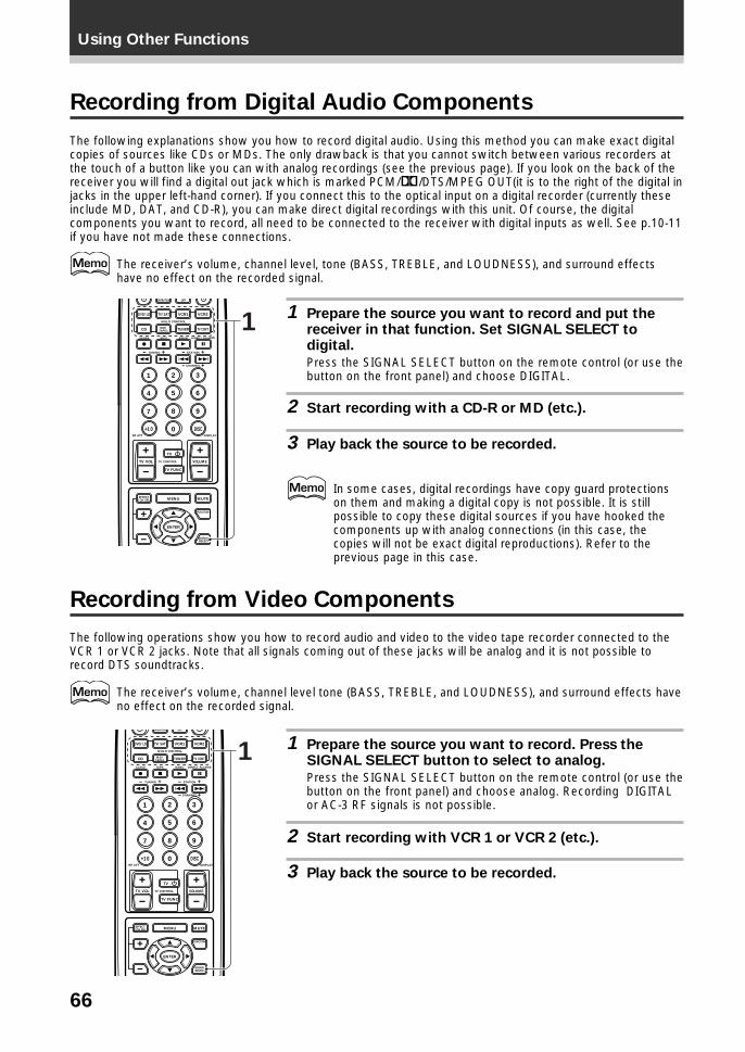
66
Using Other Functions
Recording from Video Components
The following operations show you how to record audio and video to the video tape recorder connected to theVCR 1 or VCR 2 jacks. Note that all signals coming out of these jacks will be analog and it is not possible torecord DTS soundtracks.
The receiver’s volume, channel level tone (BASS, TREBLE, and LOUDNESS), and surround effects haveno effect on the recorded signal.
1 Prepare the source you want to record. Press theSIGNAL SELECT button to select to analog.
Press the SIGNAL SELECT button on the remote control (or use thebutton on the front panel) and choose analog. Recording DIGITALor AC-3 RF signals is not possible.
2 Start recording with VCR 1 or VCR 2 (etc.).
3 Play back the source to be recorded.
DVD/LD TV/SAT VCR1 VCR2
CD
TV VOL
TV FUNC
MENU
ENTER
MUTE
TV
VOLUME
MD/TAPE1 TUNER TV CONT
OPERATION
CLASS MPX
MULTI CONTROL
DIRECT ACCESS
STATION
CHANNEL
TUNING
DISPLAYRF ATT
TV CONTROL
FUNCTION
SIGNALSELECT
EFFECT/CH SEL
/d
BAND
OFF
1 2 3
4 5 6
7
+10
8 9
0 DISC
¶ 7 3 8
1 ¡ 4 ¢ +- +-
+-
1
Recording from Digital Audio Components
The following explanations show you how to record digital audio. Using this method you can make exact digitalcopies of sources like CDs or MDs. The only drawback is that you cannot switch between various recorders atthe touch of a button like you can with analog recordings (see the previous page). If you look on the back of thereceiver you will find a digital out jack which is marked PCM/2/DTS/MPEG OUT(it is to the right of the digital injacks in the upper left-hand corner). If you connect this to the optical input on a digital recorder (currently theseinclude MD, DAT, and CD-R), you can make direct digital recordings with this unit. Of course, the digitalcomponents you want to record, all need to be connected to the receiver with digital inputs as well. See p.10-11if you have not made these connections.
The receiver’s volume, channel level, tone (BASS, TREBLE, and LOUDNESS), and surround effectshave no effect on the recorded signal.
1 Prepare the source you want to record and put thereceiver in that function. Set SIGNAL SELECT todigital.
Press the SIGNAL SELECT button on the remote control (or use thebutton on the front panel) and choose DIGITAL.
2 Start recording with a CD-R or MD (etc.).
3 Play back the source to be recorded.
In some cases, digital recordings have copy guard protectionson them and making a digital copy is not possible. It is stillpossible to copy these digital sources if you have hooked thecomponents up with analog connections (in this case, thecopies will not be exact digital reproductions). Refer to theprevious page in this case.
DVD/LD TV/SAT VCR1 VCR2
CD
TV VOL
TV FUNC
MENU
ENTER
MUTE
TV
VOLUME
MD/TAPE1 TUNER TV CONT
OPERATION
CLASS MPX
MULTI CONTROL
DIRECT ACCESS
STATION
CHANNEL
TUNING
DISPLAYRF ATT
TV CONTROL
FUNCTION
SIGNALSELECT
EFFECT/CH SEL
BAND
OFF
1 2 3
4 5 6
7
+10
8 9
0 DISC
¶ 7 3 8
1 ¡ 4 ¢ +- +-
+-
1
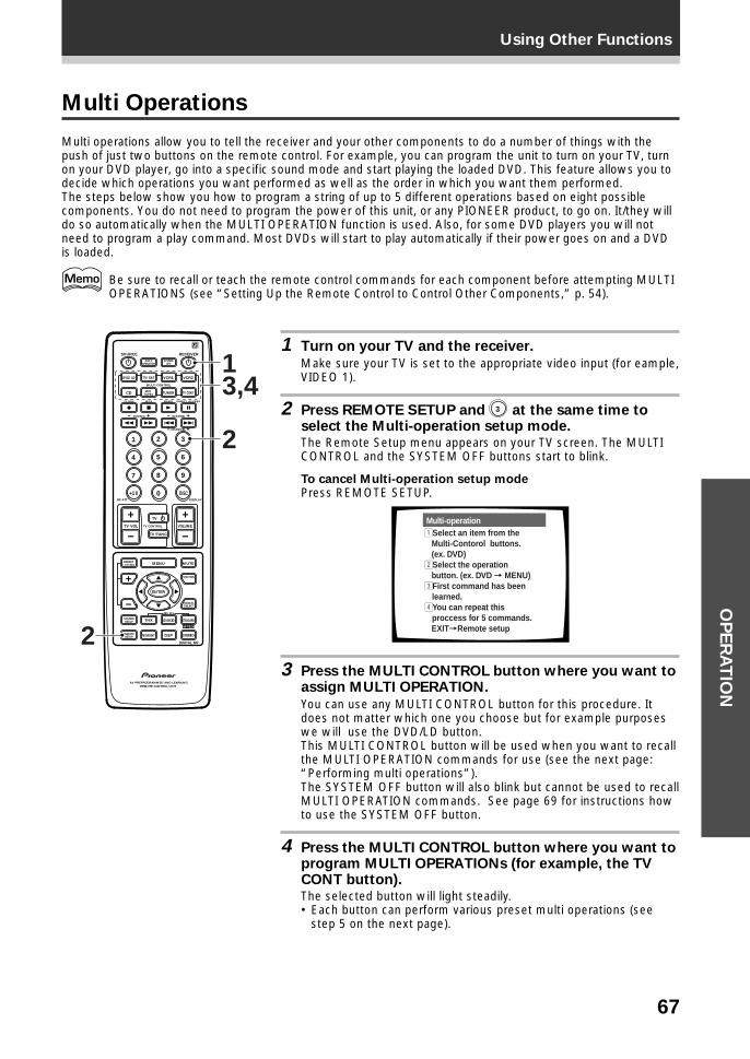
67
Using Other FunctionsO
PE
RA
TIO
N
Multi Operations
Multi operations allow you to tell the receiver and your other components to do a number of things with thepush of just two buttons on the remote control. For example, you can program the unit to turn on your TV, turnon your DVD player, go into a specific sound mode and start playing the loaded DVD. This feature allows you todecide which operations you want performed as well as the order in which you want them performed.The steps below show you how to program a string of up to 5 different operations based on eight possiblecomponents. You do not need to program the power of this unit, or any PIONEER product, to go on. It/they willdo so automatically when the MULTI OPERATION function is used. Also, for some DVD players you will notneed to program a play command. Most DVDs will start to play automatically if their power goes on and a DVDis loaded.
Be sure to recall or teach the remote control commands for each component before attempting MULTIOPERATIONS (see “Setting Up the Remote Control to Control Other Components,” p. 54).
1 Turn on your TV and the receiver.
Make sure your TV is set to the appropriate video input (for eample,VIDEO 1).
2 Press REMOTE SETUP and 3 at the same time toselect the Multi-operation setup mode.The Remote Setup menu appears on your TV screen. The MULTICONTROL and the SYSTEM OFF buttons start to blink.
To cancel Multi-operation setup modePress REMOTE SETUP.
Multi-operation1Select an item from the Multi-Contorol buttons. (ex. DVD)2Select the operation button. (ex. DVD = MENU)3First command has been
learned.4You can repeat this
proccess for 5 commands. EXIT=Remote setup
3 Press the MULTI CONTROL button where you want toassign MULTI OPERATION.
You can use any MULTI CONTROL button for this procedure. Itdoes not matter which one you choose but for example purposeswe will use the DVD/LD button.This MULTI CONTROL button will be used when you want to recallthe MULTI OPERATION commands for use (see the next page:“Performing multi operations”).The SYSTEM OFF button will also blink but cannot be used to recallMULTI OPERATION commands. See page 69 for instructions howto use the SYSTEM OFF button.
4 Press the MULTI CONTROL button where you want toprogram MULTI OPERATIONs (for example, the TVCONT button).The selected button will light steadily.• Each button can perform various preset multi operations (see
step 5 on the next page).
S0URCE
DVD/LD TV/SAT VCR1 VCR2
CD
TV VOL
TV FUNC
MENU
ENTER
STEREO
DIGITAL NR
MIDNIGHT
ADVANCED STANDARD
DSP
THX
MUTE
TV
VOLUME
MD/TAPE1 TUNER TV CONT
RECEIVER
MULTIOPERATION
CLASS MPX
MULTI CONTROL
DIRECT ACCESS
STATION
CHANNEL
TUNING
DISPLAYRF ATT
TV CONTROL
FUNCTION
SIGNALSELECT
EFFECT/CH SEL
2/dts
AV PREPROGRAMMED AND LEARNINGREMOTE CONTROL UNIT
REMOTESETUP
SYSTEMSETUP
BAND
SYSTEMOFF
1 2 3
4 5 6
7
+10
8 9
0 DISC
Î
¶ 7 3 8
1 ¡ 4 ¢ +- +-
+-
MPEG
3,4
2
2
1
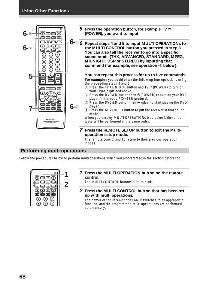
68
Using Other Functions
5 Press the operation button, for example TV (POWER), you want to input.
6 Repeat steps 4 and 5 to input MULTI OPERATIONs tothe MULTI CONTROL button you pressed in step 3.You can also tell the receiver to go into a specificsound mode (THX, ADVANCED, STANDARD, MPEG,MIDNIGHT, DSP or STEREO) by inputting thatcommand (for example, see operation 4 below).
You can repeat this process for up to five commands.
For example : you could enter the following four operations usingthe preceeding steps 4 and 5.1 Press the TV CONTROL button and TV (POWER) to turn on
your TV(as explained above).2 Press the DVD/LD button then (POWER) to turn on your DVD
player (if it is not a PIONEER product).3 Press the DVD/LD button then 3 (play) to start playing the DVD
player.4 Press the ADVANCED button to put the receiver in that sound
mode.When you employ MULTI OPERATIONs (see below), these fourtasks will be performed in the same order.
7 Press the REMOTE SETUP button to exit the Multi-operation setup mode.
The remote control and TV return to their previous operationmodes.
Performing multi operations
Follow the procedures below to perform multi operations which you programmed in the section before this.
1 Press the MULTI OPERATION button on the remotecontrol.The MULTI CONTROL buttons start to blink.
2 Press the MULTI CONTROL button that has been setup with multi operations.
The power of the receiver goes on, it switches to an appropriatefunction, and the programmed multi opearations are performedautomatically.
S0URCE
DVD/LD TV/SAT VCR1 VCR2
CD
TV VOL
TV FUNC
MENU
ENTER
STEREO
DIGITAL NR
MIDNIGHT
ADVANCED STANDARD
DSP
THX
MUTE
TV
VOLUME
MD/TAPE1 TUNER TV CONT
RECEIVER
MULTIOPERATION
CLASS MPX
MULTI CONTROL
DIRECT ACCESS
STATION
CHANNEL
TUNING
DISPLAYRF ATT
TV CONTROL
FUNCTION
SIGNALSELECT
EFFECT/CH SEL
2/dts
AV PREPROGRAMMED AND LEARNINGREMOTE CONTROL UNIT
REMOTESETUP
SYSTEMSETUP
BAND
SYSTEMOFF
1 2 3
4 5 6
7
+10
8 9
0 DISC
Î
¶ 7 3 8
1 ¡ 4 ¢ +- +-
+-
MPEG
7
5
6-2
6-3
6-1
6-4
S0URCE
DVD/LD TV/SAT VCR1 VCR2
CD MD/TAPE1 TUNER TV CONT
RECEIVER
MULTIOPERATION
CLASS MPX
MULTI CONTROL
DIRECT ACCESS
STATION
CHANNEL
TUNING
BAND
SYSTEMOFF
1 2 3
4 5 6
Î
¶ 7 3 8
1 ¡ 4 ¢ +- +-
+-
2
1

69
Using Other FunctionsO
PE
RA
TIO
N
Using the SYSTEM OFF button
This button will turn off the receiver and any component that has programmed into the SYSTEM OFF settings(see above) as well as turn off all PIONEER components regardless of whether they have been programmedinto SYSTEM OFF. If you use this feature when a DVD is playing, the player will stop the play mode beforeswitching off.
Press the SYSTEM OFF button on the remote control.S0URCE
DVD/LD TV/SAT VCR1 VCR2
CD MD/TAPE1 TUNER TV CONT
RECEIVER
MULTIOPERATION
MULTI CONTROL
SYSTEMOFF
Î SYSTEMOFF
System OFF
The SYSTEM OFF feature allows you to tell the receiver and your other components to stop and turn off withthe push of only one button on the remote control. For example, you can program the unit to stop your DVD,turn off your TV, turn off your DVD player and turn off the receiver itself. You do not need to program in otherthe power for PIONEER components, they will go off automatically in this mode. The receiver itself will go offautomatically as well.The steps below show you how to program a string of up to 5 different SYSTEM OFF operations based on eightpossible components.
Be sure to recall or teach the remote control commands for each component before attemptingMULTI OPERATIONS (see “Setting Up the Remote Control to Control Other Components”, p.54).
1 Press the REMOTE SETUP button and the 3 button
at the same time to select the MULTI OPERATIONSETUP mode.
The REMOTE SETUP menu appears on your TV screen. The MULTICONTROL and the SYSTEM OFF buttons start to blink.
To cancel MULTI OPERATION SETUP modePress REMOTE SETUP.
2 Press the SYSTEM OFF button.
The SYSTEM OFF button will blink.
3 Press the MULTI CONTROL button where you want toassign SYSTEM OFF (for esample, the TV CONTbutton).
The selected button will light steadily.
4 Press the operation, for example TV (POWER), youwant to input.
5 Repeat steps 3 and 4 to input SYSTEM OFF for thecomponents and commands you want to input.You can repeat this process for up to five commands.For example: you could enter the following two operations usingthe proceeding steps 3 and 4.1 Press TV CONT button and TV (POWER) to turn off your TV
(as explained above).2 Press DVD/LD then (POWER) to turn off your DVD player (if it
is not a PIONEER product).When you employ SYSTEM OFF (see below), these two taskswill be performed in the same order.
To exit SYSTEM OFF SETUP modePress REMOTE SETUP
S0URCE
DVD/LD TV/SAT VCR1 VCR2
CD
TV VOL
TV FUNC
MENU
ENTER
STEREO
DIGITAL NR
MIDNIGHT
ADVANCED STANDARD
DSP
THX
MUTE
TV
VOLUME
MD/TAPE1 TUNER TV CONT
RECEIVER
MULTIOPERATION
CLASS MPX
MULTI CONTROL
DIRECT ACCESS
STATION
CHANNEL
TUNING
DISPLAYRF ATT
TV CONTROL
FUNCTION
SIGNALSELECT
EFFECT/CH SEL
2/dts
AV PREPROGRAMMED AND LEARNINGREMOTE CONTROL UNIT
REMOTESETUP
SYSTEMSETUP
BAND
SYSTEMOFF
1 2 3
4 5 6
7
+10
8 9
0 DISC
Î
¶ 7 3 8
1 ¡ 4 ¢ +- +-
+-
MPEG
1
5-2
5-1
2
3
4
1
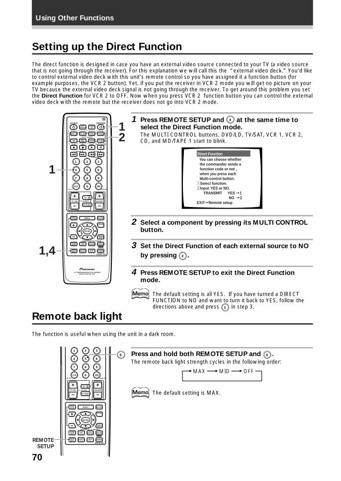
70
Using Other Functions
Setting up the Direct Function
The direct function is designed in case you have an external video source connected to your TV (a video sourcethat is not going through the receiver). For this explanation we will call this the “external video deck.” You’d liketo control external video deck with this unit’s remote control so you have assigned it a function button (forexample purposes, the VCR 2 button). Yet, if you put the receiver in VCR 2 mode you will get no picture on yourTV because the external video deck signal is not going through the receiver. To get around this problem you setthe Direct Function for VCR 2 to OFF. Now when you press VCR 2 function button you can control the externalvideo deck with the remote but the receiver does not go into VCR 2 mode.
1 Press REMOTE SETUP and 4 at the same time toselect the Direct Function mode.The MULTI CONTROL buttons, DVD/LD, TV/SAT, VCR 1, VCR 2,CD, and MD/TAPE 1 start to blink.
Direct Function You can choose whether the commander sends a function code or not , when you press each Multi-control button.1Select function.2Input YES or NO. TRANSMIT YES =1 NO =2EXIT=Remote setup
2 Select a component by pressing its MULTI CONTROLbutton.
3 Set the Direct Function of each external source to NO
by pressing 2 .
4 Press REMOTE SETUP to exit the Direct Functionmode.
The default setting is all YES. If you have turned a DIRECTFUNCTION to NO and want to turn it back to YES, follow thedirections above and press 1 in step 3.
S0URCE
DVD/LD TV/SAT VCR1 VCR2
CD
TV VOL
TV FUNC
MENU
ENTER
STEREO
DIGITAL NR
MIDNIGHT
ADVANCED STANDARD
DSP
THX
MUTE
TV
VOLUME
MD/TAPE1 TUNER TV CONT
RECEIVER
MULTIOPERATION
CLASS MPX
MULTI CONTROL
DIRECT ACCESS
STATION
CHANNEL
TUNING
DISPLAYRF ATT
TV CONTROL
FUNCTION
SIGNALSELECT
EFFECT/CH SEL
2/dts
AV PREPROGRAMMED AND LEARNINGREMOTE CONTROL UNIT
REMOTESETUP
SYSTEMSETUP
BAND
SYSTEMOFF
1 2 3
4 5 6
7
+10
8 9
0 DISC
Î
¶ 7 3 8
1 ¡ 4 ¢ +- +-
+-
MPEG
1,4
1
21
Remote back light
The function is useful when using the unit in a dark room.
Press and hold both REMOTE SETUP and 5 .
The remote back light strength cycles in the following order:
MAX OFFMID
The default setting is MAX.TV VOL
TV FUNC
MENU
ENTER
STEREO
DIGITAL NR
MIDNIGHT
ADVANCED STANDARD
DSP
THX
MUTE
TV
VOLUME
DISPLAYRF ATT
TV CONTROL
FUNCTION
SIGNALSELECT
EFFECT/CH SEL
2/dts
REMOTESETUP
SYSTEMSETUP
1 2 3
4 5 6
7
+10
8 9
0 DISC
MPEG
REMOTESETUP
5
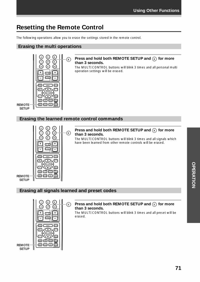
71
Using Other FunctionsO
PE
RA
TIO
N
Erasing the learned remote control commands
Press and hold both REMOTE SETUP and 9 for morethan 3 seconds.
The MULTI CONTROL buttons will blink 3 times and all signals whichhave been learned from other remote controls will be erased.
Erasing all signals learned and preset codes
Press and hold both REMOTE SETUP and 0 for morethan 3 seconds.The MULTI CONTROL buttons will blink 3 times and all preset will beerased.
Resetting the Remote Control
The following operations allow you to erase the settings stored in the remote control.
Erasing the multi operations
Press and hold both REMOTE SETUP and 8 for morethan 3 seconds.
The MULTI CONTROL buttons will blink 3 times and all personal multioperation settings will be erased.
TV VOL
TV FUNC
MENU
ENTER
STEREO
DIGITAL NR
MIDNIGHT
ADVANCED STANDARD
DSP
THX
MUTE
TV
VOLUME
DISPLAYRF ATT
TV CONTROL
FUNCTION
SIGNALSELECT
EFFECT/CH SEL
2/dts
REMOTESETUP
SYSTEMSETUP
4 5 6
7
+10
8 9
0 DISC
MPEG
8
REMOTESETUP
TV VOL
TV FUNC
MENU
ENTER
STEREO
DIGITAL NR
MIDNIGHT
ADVANCED STANDARD
DSP
THX
MUTE
TV
VOLUME
DISPLAYRF ATT
TV CONTROL
FUNCTION
SIGNALSELECT
EFFECT/CH SEL
2/dts
REMOTESETUP
SYSTEMSETUP
4 5 6
7
+10
8 9
0 DISC
MPEG
9
REMOTESETUP
TV VOL
TV FUNC
MENU
ENTER
STEREO
DIGITAL NR
MIDNIGHT
ADVANCED STANDARD
DSP
THX
MUTE
TV
VOLUME
DISPLAYRF ATT
TV CONTROL
FUNCTION
SIGNALSELECT
EFFECT/CH SEL
2/dts
REMOTESETUP
SYSTEMSETUP
7
+10
8 9
0 DISC
MPEG
0
REMOTESETUP
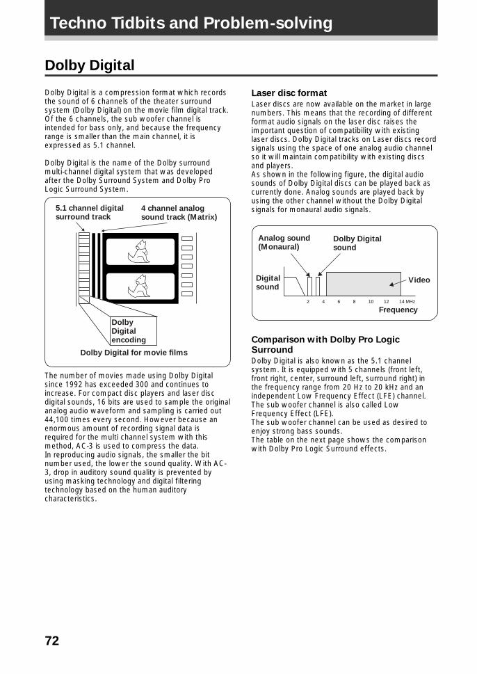
72
Dolby Digital
Dolby Digital is a compression format which recordsthe sound of 6 channels of the theater surroundsystem (Dolby Digital) on the movie film digital track.Of the 6 channels, the sub woofer channel isintended for bass only, and because the frequencyrange is smaller than the main channel, it isexpressed as 5.1 channel.
Dolby Digital is the name of the Dolby surroundmulti-channel digital system that was developedafter the Dolby Surround System and Dolby ProLogic Surround System.
The number of movies made using Dolby Digitalsince 1992 has exceeded 300 and continues toincrease. For compact disc players and laser discdigital sounds, 16 bits are used to sample the originalanalog audio waveform and sampling is carried out44,100 times every second. However because anenormous amount of recording signal data isrequired for the multi channel system with thismethod, AC-3 is used to compress the data.In reproducing audio signals, the smaller the bitnumber used, the lower the sound quality. With AC-3, drop in auditory sound quality is prevented byusing masking technology and digital filteringtechnology based on the human auditorycharacteristics.
Laser disc format
Laser discs are now available on the market in largenumbers. This means that the recording of differentformat audio signals on the laser disc raises theimportant question of compatibility with existinglaser discs. Dolby Digital tracks on Laser discs recordsignals using the space of one analog audio channelso it will maintain compatibility with existing discsand players.As shown in the following figure, the digital audiosounds of Dolby Digital discs can be played back ascurrently done. Analog sounds are played back byusing the other channel without the Dolby Digitalsignals for monaural audio signals.
Comparison with Dolby Pro LogicSurround
Dolby Digital is also known as the 5.1 channelsystem. It is equipped with 5 channels (front left,front right, center, surround left, surround right) inthe frequency range from 20 Hz to 20 kHz and anindependent Low Frequency Effect (LFE) channel.The sub woofer channel is also called LowFrequency Effect (LFE).The sub woofer channel can be used as desired toenjoy strong bass sounds.The table on the next page shows the comparisonwith Dolby Pro Logic Surround effects.
Techno Tidbits and Problem-solving
5.1 channel digital surround track
4 channel analog sound track (Matrix)
Dolby Digital encoding
Dolby Digital for movie films
2 4 6 8 10 12 14 MHz
Video
Frequency
Digital sound
Analog sound (Monaural)
Dolby Digital sound
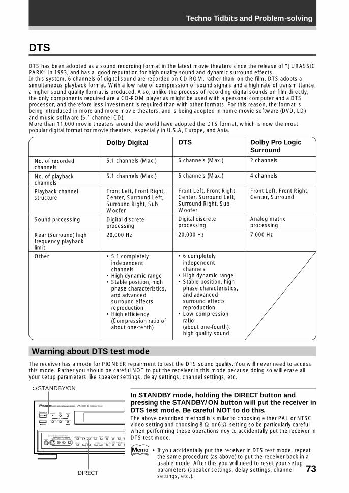
73
Techno Tidbits and Problem-solving
DTS
DTS has been adopted as a sound recording format in the latest movie theaters since the release of “JURASSICPARK” in 1993, and has a good reputation for high quality sound and dynamic surround effects.In this system, 6 channels of digital sound are recorded on CD-ROM, rather than on the film. DTS adopts asimultaneous playback format. With a low rate of compression of sound signals and a high rate of transmittance,a higher sound quality format is produced. Also, unlike the process of recording digital sounds on film directly,the only components required are a CD-ROM player as might be used with a personal computer and a DTSprocessor, and therefore less investment is required than with other formats. For this reason, the format isbeing introduced in more and more movie theaters, and is being adopted in home movie software (DVD, LD)and music software (5.1 channel CD).More than 11,000 movie theaters around the world have adopted the DTS format, which is now the mostpopular digital format for movie theaters, especially in U.S.A, Europe, and Asia.
No. of recordedchannels
No. of playbackchannels
Playback channelstructure
Sound processing
Rear (Surround) highfrequency playbacklimit
Other
Dolby Digital
5.1 channels (Max.)
5.1 channels (Max.)
Front Left, Front Right,Center, Surround Left,Surround Right, SubWoofer
Digital discreteprocessing
20,000 Hz
• 5.1 completelyindependentchannels
• High dynamic range• Stable position, high
phase characteristics,and advancedsurround effectsreproduction
• High efficiency(Compression ratio ofabout one-tenth)
DTS
6 channels (Max.)
6 channels (Max.)
Front Left, Front Right,Center, Surround Left,Surround Right, SubWoofer
Digital discreteprocessing
20,000 Hz
• 6 completelyindependentchannels
• High dynamic range• Stable position, high
phase characteristics,and advancedsurround effectsreproduction
• Low compressionratio(about one-fourth),high quality sound
Dolby Pro LogicSurround
2 channels
4 channels
Front Left, Front Right,Center, Surround
Analog matrixprocessing
7,000 Hz
Warning about DTS test mode
The receiver has a mode for PIONEER repairment to test the DTS sound quality. You will never need to accessthis mode. Rather you should be careful NOT to put the receiver in this mode because doing so will erase allyour setup parameters like speaker settings, delay settings, channel settings, etc.
STANDBY/ON
—OFF _ON
DSPMODESTANDBY
AUDIO/VIDEO MULTI-CHANNEL RECEIVER
STEREO
PHONES S-VIDEO
5-CHANNEL EQUAL POWER OUTPUT
VIDEO
EXTERNALDECODER IN
TAPE 2MONITOR
DIRECT LOUDNESS MIDNIGHTDIGITAL
NR CLASS FM/
MEMCHARACTER/SEARCHINPUT ATTSPEAKERS – TREBLE +– BASS +
L AUDIO RVIDEO INPUT
THX CINEMA ADVANCED STANDARD
/DTS
MPEG
RF ATTSIGNALSELECT
DIRECT
STANDBY/ONIn STANDBY mode, holding the DIRECT button andpressing the STANDBY/ON button will put the receiver inDTS test mode. Be careful NOT to do this.
The above described method is similar to choosing either PAL or NTSCvideo setting and choosing 8 Ω or 6 Ω setting so be particularly carefulwhen performing these operations noy to accidentally put the receiver inDTS test mode.
• If you accidentally put the receiver in DTS test mode, repeatthe same procedure (as above) to put the receiver back in ausable mode. After this you will need to reset your setupparameters (speaker settings, delay settings, channelsettings, etc.).
74
Techno Tidbits and Problem-solving
MPEG Audio
MPEG is an audio encoding system which delivers high quality audio for music and movies. By removingfrequencies which are out of the human hearing range, the sound is then compressed to enable thetransmission of mono, stereo, or multichannel (5.1 and 7.1) audio in a single bitstream which is why it hasbecome a standard audio format for DVD and personal computers. The composition and versatility of MPEGaudio also ensures that the presentation of a multichannel soundtrack will sound appropriate on everything froma 7.1 channel surround sound home theater setup to a mono television set. Above all, MPEG audio is designedto be compatible with past and future MPEG audio versions, which means that future versions of MPEG audiowill be compatible with decoders currently being produced (the signal is merely reconfigured to fit the number ofchannels available in a system).
THX
THX is a Lucasfilm, Ltd. program dedicated tomaximum accuracy in movie presentation. Moviesound tracks are recorded in large movie dubbingstages using movie theater equipment. For a soundtrack to be presented accurately in your home,special technologies are required. In your home theroom is much smaller and has a bright sound, thespeakers are very different and there are only six ofthem, plus, you sit much closer to each one of thosespeakers. Because of these differences we oftenmiss the power and emotion that thrills us in a goodmovie. Now Pioneer and THX have teamed up tobring the full glory of accurate cinema sound to thecomfort and convenience of your home.
Re-Equalization™ : In a theater the room is verylarge and dead sounding, you sit a long way backfrom the speakers and the speakers themselves arevery specialized. Because a sound track recorded inthis dead sounding space when it is played at homeit sounds overbright. THX Re-Equalization adjusts forthis difference in a very precise way.
Dynamic Decorrelation™ : When a sound tracksends mono sound to the surround speakers it oftenseems to be coming come from one side instead offrom all around you as it would in a theater. DynamicDecorrelation helps to correct this inaccuracy.
Timbre Matching™ : When recording a sound trackit is very important that the surround sounds movesmoothly and seamlessly around the theater. It isvery distracting when sounds seem to jump fromspeaker to speaker. Timbre Matching helps tosmooth the movement of the surround sounds eventhough you are using only two speakers.
Bass Peak Level Manager™ : Some Dolby Digitaland DTS soundtracks can produce bass peaks thatare undesirable in a home theater environment. TheBass Peak Level Manager allows you to set themaximum peak levels appropriate to your system.(Set this function according to the bass peak levelinstructions on page 32.)
Loudspeaker Position Time Synchronization™ :This feature allows you to adjust for the difference inthe distance from each individual loudspeaker to thelistening position. Doing this ensures that all thespeakers operate in precise synchronizationimproving the seamless nature of the soundfield.(Set this function according to the channel delayinstructions on page 28.)
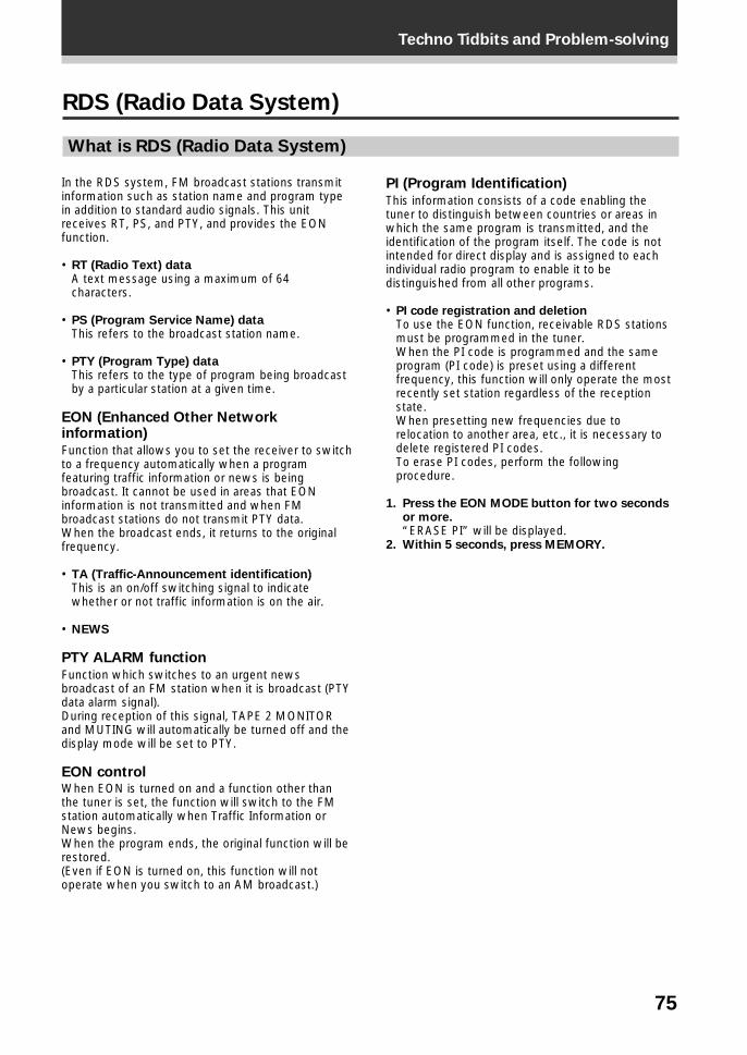
75
Techno Tidbits and Problem-solving
In the RDS system, FM broadcast stations transmitinformation such as station name and program typein addition to standard audio signals. This unitreceives RT, PS, and PTY, and provides the EONfunction.
• RT (Radio Text) dataA text message using a maximum of 64characters.
• PS (Program Service Name) dataThis refers to the broadcast station name.
• PTY (Program Type) dataThis refers to the type of program being broadcastby a particular station at a given time.
EON (Enhanced Other Networkinformation)
Function that allows you to set the receiver to switchto a frequency automatically when a programfeaturing traffic information or news is beingbroadcast. It cannot be used in areas that EONinformation is not transmitted and when FMbroadcast stations do not transmit PTY data.When the broadcast ends, it returns to the originalfrequency.
• TA (Traffic-Announcement identification)This is an on/off switching signal to indicatewhether or not traffic information is on the air.
• NEWS
PTY ALARM function
Function which switches to an urgent newsbroadcast of an FM station when it is broadcast (PTYdata alarm signal).During reception of this signal, TAPE 2 MONITORand MUTING will automatically be turned off and thedisplay mode will be set to PTY.
EON controlWhen EON is turned on and a function other thanthe tuner is set, the function will switch to the FMstation automatically when Traffic Information orNews begins.When the program ends, the original function will berestored.(Even if EON is turned on, this function will notoperate when you switch to an AM broadcast.)
RDS (Radio Data System)
What is RDS (Radio Data System)
PI (Program Identification)
This information consists of a code enabling thetuner to distinguish between countries or areas inwhich the same program is transmitted, and theidentification of the program itself. The code is notintended for direct display and is assigned to eachindividual radio program to enable it to bedistinguished from all other programs.
• PI code registration and deletionTo use the EON function, receivable RDS stationsmust be programmed in the tuner.When the PI code is programmed and the sameprogram (PI code) is preset using a differentfrequency, this function will only operate the mostrecently set station regardless of the receptionstate.When presetting new frequencies due torelocation to another area, etc., it is necessary todelete registered PI codes.To erase PI codes, perform the followingprocedure.
1. Press the EON MODE button for two secondsor more.“ERASE PI” will be displayed.
2. Within 5 seconds, press MEMORY.
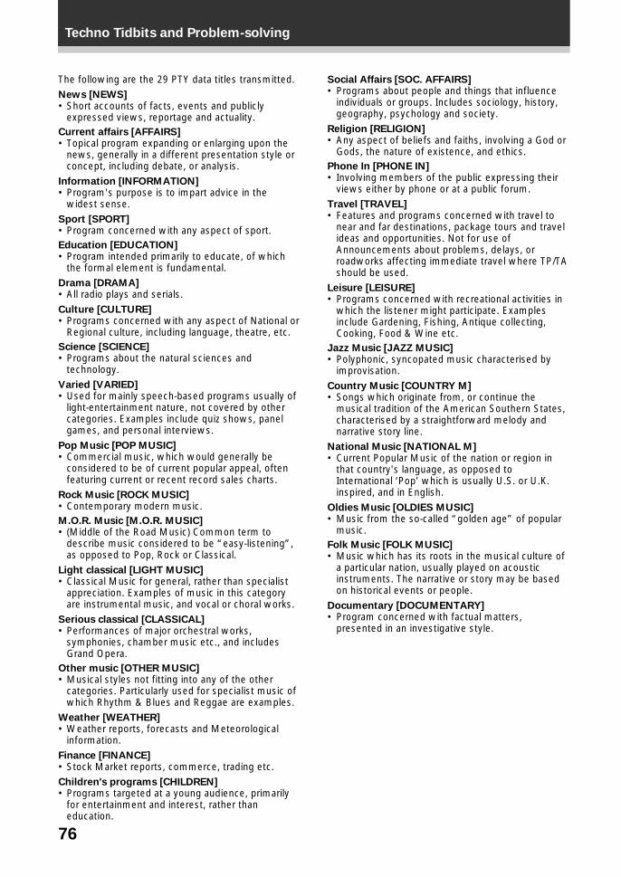
76
Techno Tidbits and Problem-solving
The following are the 29 PTY data titles transmitted.News [NEWS]• Short accounts of facts, events and publicly
expressed views, reportage and actuality.Current affairs [AFFAIRS]• Topical program expanding or enlarging upon the
news, generally in a different presentation style orconcept, including debate, or analysis.
Information [INFORMATION]• Program's purpose is to impart advice in the
widest sense.Sport [SPORT]• Program concerned with any aspect of sport.Education [EDUCATION]• Program intended primarily to educate, of which
the formal element is fundamental.Drama [DRAMA]• All radio plays and serials.Culture [CULTURE]• Programs concerned with any aspect of National or
Regional culture, including language, theatre, etc.Science [SCIENCE]• Programs about the natural sciences and
technology.Varied [VARIED]• Used for mainly speech-based programs usually of
light-entertainment nature, not covered by othercategories. Examples include quiz shows, panelgames, and personal interviews.
Pop Music [POP MUSIC]• Commercial music, which would generally be
considered to be of current popular appeal, oftenfeaturing current or recent record sales charts.
Rock Music [ROCK MUSIC]• Contemporary modern music.M.O.R. Music [M.O.R. MUSIC]• (Middle of the Road Music) Common term to
describe music considered to be “easy-listening”,as opposed to Pop, Rock or Classical.
Light classical [LIGHT MUSIC]• Classical Music for general, rather than specialist
appreciation. Examples of music in this categoryare instrumental music, and vocal or choral works.
Serious classical [CLASSICAL]• Performances of major orchestral works,
symphonies, chamber music etc., and includesGrand Opera.
Other music [OTHER MUSIC]• Musical styles not fitting into any of the other
categories. Particularly used for specialist music ofwhich Rhythm & Blues and Reggae are examples.
Weather [WEATHER]• Weather reports, forecasts and Meteorological
information.Finance [FINANCE]• Stock Market reports, commerce, trading etc.Children's programs [CHILDREN]• Programs targeted at a young audience, primarily
for entertainment and interest, rather thaneducation.
Social Affairs [SOC. AFFAIRS]• Programs about people and things that influence
individuals or groups. Includes sociology, history,geography, psychology and society.
Religion [RELIGION]• Any aspect of beliefs and faiths, involving a God or
Gods, the nature of existence, and ethics.Phone In [PHONE IN]• Involving members of the public expressing their
views either by phone or at a public forum.Travel [TRAVEL]• Features and programs concerned with travel to
near and far destinations, package tours and travelideas and opportunities. Not for use ofAnnouncements about problems, delays, orroadworks affecting immediate travel where TP/TAshould be used.
Leisure [LEISURE]• Programs concerned with recreational activities in
which the listener might participate. Examplesinclude Gardening, Fishing, Antique collecting,Cooking, Food & Wine etc.
Jazz Music [JAZZ MUSIC]• Polyphonic, syncopated music characterised by
improvisation.Country Music [COUNTRY M]• Songs which originate from, or continue the
musical tradition of the American Southern States,characterised by a straightforward melody andnarrative story line.
National Music [NATIONAL M]• Current Popular Music of the nation or region in
that country's language, as opposed toInternational ‘Pop’ which is usually U.S. or U.K.inspired, and in English.
Oldies Music [OLDIES MUSIC]• Music from the so-called “golden age” of popular
music.Folk Music [FOLK MUSIC]• Music which has its roots in the musical culture of
a particular nation, usually played on acousticinstruments. The narrative or story may be basedon historical events or people.
Documentary [DOCUMENTARY]• Program concerned with factual matters,
presented in an investigative style.
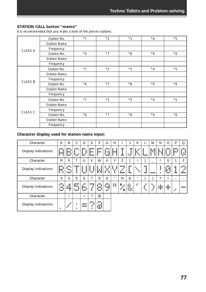
77
Techno Tidbits and Problem-solving
*1
*6
Station No.Station Name
FrequencyStation No.
Station NameFrequency
CLASS A
CLASS B
CLASS C
Station No.Station Name
FrequencyStation No.
Station NameFrequency
Station No.Station Name
FrequencyStation No.
Station NameFrequency
STATION CALL button “memo”
It is recommended that you make a note of the preset stations.
Character display used for station name input:
*1
*6
*1
*6
*2
*7
*2
*7
*2
*7
*3
*8
*3
*8
*3
*8
*4
*9
*4
*9
*4
*9
*5
*0
*5
*0
*5
*0
0 1 2
3 4 5 6 7 8 9
!
" % & ' ( ) * + , -
. / : = ? @
A B C D E F G H I J K L M N O P Q
R
Character
Character
Character
Character
Display indications
Display indications
Display indications
Display indications
S T U V W X Y Z [ \ ] _
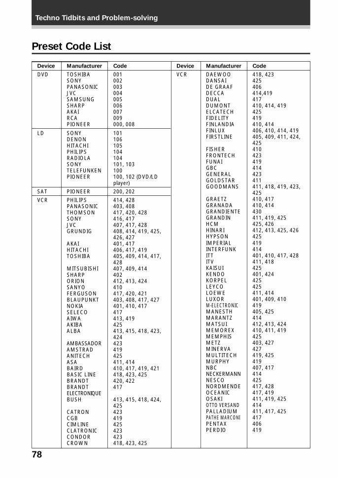
78
Techno Tidbits and Problem-solving
Preset Code List
Device
DVD
LD
SAT
VCR
Manufacturer
TOSHIBASONYPANASONICJVCSAMSUNGSHARPAKAIRCAPIONEER
SONYDENONHITACHIPHILIPSRADIOLASONYTELEFUNKENPIONEER
PIONEER
PHILIPSPANASONICTHOMSONSONYJVCGRUNDIG
AKAIHITACHITOSHIBA
MITSUBISHISHARPORIONSANYOFERGUSONBLAUPUNKTNOKIASELECOAIWAAKIBAALBA
AMBASSADORAMSTRADANITECHASABAIRDBASIC LINEBRANDTBRANDTELECTRONIQUEBUSH
CATRONCGBCIMLINECLATRONICCONDORCROWN
Code
001002003004005006007009000, 008
101106105104104101, 103100100, 102 (DVD/LDplayer)
200, 202
414, 428403, 408417, 420, 428416, 417407, 417, 428408, 414, 419, 425,426, 427401, 417406, 417, 419405, 409, 414, 417,428407, 409, 414402412, 413, 424410417, 420, 421403, 408, 417, 427401, 410, 417417413, 419425413, 415, 418, 423,424423419425411, 414410, 417, 419, 421418, 423, 425420, 422417
413, 415, 418, 424,425423419425423423418, 423, 425
Device
VCR
Manufacturer
DAEWOODANSAIDE GRAAFDECCADUALDUMONTELCATECHFIDELITYFINLANDIAFINLUXFIRSTLINE
FISHERFRONTECHFUNAIGBCGENERALGOLDSTARGOODMANS
GRAETZGRANADAGRANDIENTEGRANDINHCMHINARIHYPSONIMPERIALINTERFUNKITTITVKAISUIKENDOKORPELLEYCOLOEWELUXORM-ELECTRONICMANESTHMARANTZMATSUIMEMOREXMEMPHISMETZMINERVAMULTITECHMURPHYNBCNECKERMANNNESCONORDMENDEOCEANICOSAKIOTTO VERSANDPALLADIUMPATHE MARCONIPENTAXPERDIO
Code
418, 423425406414,419417410, 414, 419425419410, 414406, 410, 414, 419405, 409, 411, 424,425410423419414423411411, 418, 419, 423,425410, 417410, 414430411, 419, 425425, 426412, 413, 425, 426425419414401, 410, 417, 428411, 418425401, 424425425411, 414401, 409, 410419405, 425414412, 413, 424410, 411, 419425403, 427427419, 425419407, 417414425417, 428417, 419411, 419, 425414411, 417, 425417406419
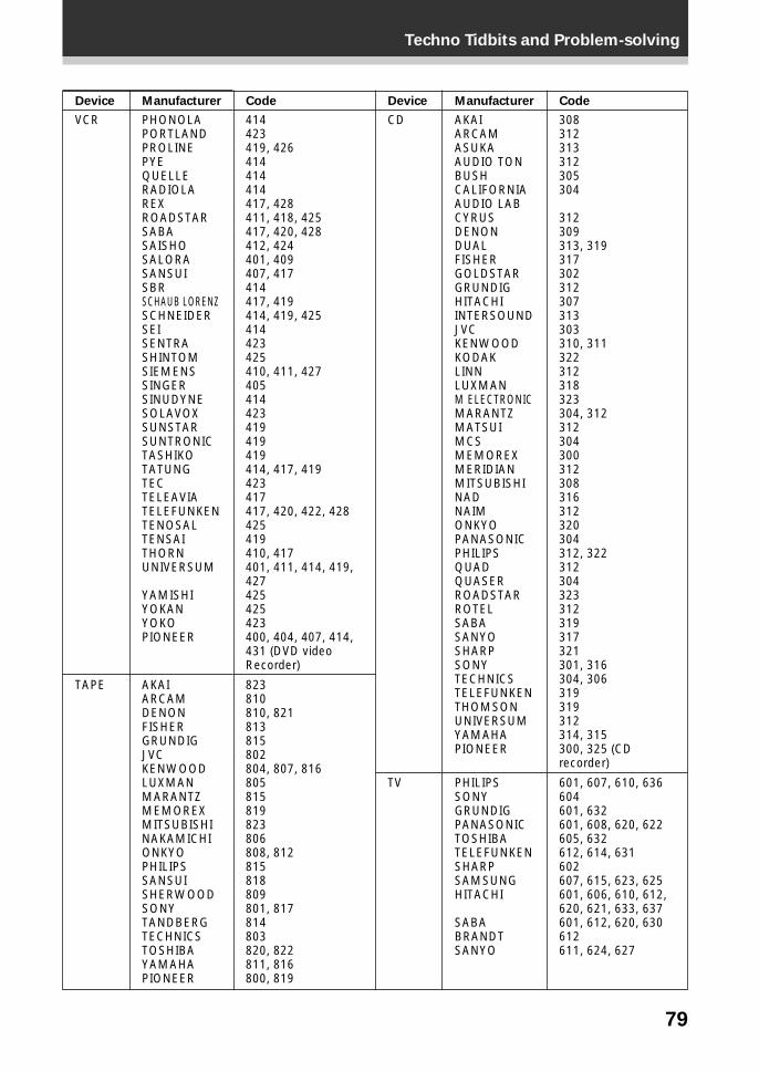
79
Techno Tidbits and Problem-solving
Device
VCR
TAPE
Manufacturer
PHONOLAPORTLANDPROLINEPYEQUELLERADIOLAREXROADSTARSABASAISHOSALORASANSUISBRSCHAUB LORENZSCHNEIDERSEISENTRASHINTOMSIEMENSSINGERSINUDYNESOLAVOXSUNSTARSUNTRONICTASHIKOTATUNGTECTELEAVIATELEFUNKENTENOSALTENSAITHORNUNIVERSUM
YAMISHIYOKANYOKOPIONEER
AKAIARCAMDENONFISHERGRUNDIGJVCKENWOODLUXMANMARANTZMEMOREXMITSUBISHINAKAMICHIONKYOPHILIPSSANSUISHERWOODSONYTANDBERGTECHNICSTOSHIBAYAMAHAPIONEER
Code
414423419, 426414414414417, 428411, 418, 425417, 420, 428412, 424401, 409407, 417414417, 419414, 419, 425414423425410, 411, 427405414423419419419414, 417, 419423417417, 420, 422, 428425419410, 417401, 411, 414, 419,427425425423400, 404, 407, 414,431 (DVD videoRecorder)
823810810, 821813815802804, 807, 816805815819823806808, 812815818809801, 817814803820, 822811, 816800, 819
Device
CD
TV
Manufacturer
AKAIARCAMASUKAAUDIO TONBUSHCALIFORNIAAUDIO LABCYRUSDENONDUALFISHERGOLDSTARGRUNDIGHITACHIINTERSOUNDJVCKENWOODKODAKLINNLUXMANM ELECTRONICMARANTZMATSUIMCSMEMOREXMERIDIANMITSUBISHINADNAIMONKYOPANASONICPHILIPSQUADQUASERROADSTARROTELSABASANYOSHARPSONYTECHNICSTELEFUNKENTHOMSONUNIVERSUMYAMAHAPIONEER
PHILIPSSONYGRUNDIGPANASONICTOSHIBATELEFUNKENSHARPSAMSUNGHITACHI
SABABRANDTSANYO
Code
308312313312305304
312309313, 319317302312307313303310, 311322312318323304, 312312304300312308316312320304312, 322312304323312319317321301, 316304, 306319319312314, 315300, 325 (CDrecorder)
601, 607, 610, 636604601, 632601, 608, 620, 622605, 632612, 614, 631602607, 615, 623, 625601, 606, 610, 612,620, 621, 633, 637601, 612, 620, 630612611, 624, 627
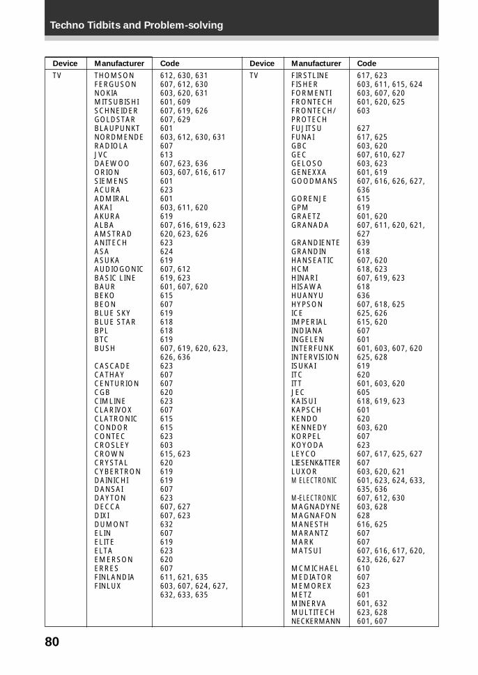
80
Techno Tidbits and Problem-solving
Device
TV
Manufacturer
THOMSONFERGUSONNOKIAMITSUBISHISCHNEIDERGOLDSTARBLAUPUNKTNORDMENDERADIOLAJVCDAEWOOORIONSIEMENSACURAADMIRALAKAIAKURAALBAAMSTRADANITECHASAASUKAAUDIOGONICBASIC LINEBAURBEKOBEONBLUE SKYBLUE STARBPLBTCBUSH
CASCADECATHAYCENTURIONCGBCIMLINECLARIVOXCLATRONICCONDORCONTECCROSLEYCROWNCRYSTALCYBERTRONDAINICHIDANSAIDAYTONDECCADIXIDUMONTELINELITEELTAEMERSONERRESFINLANDIAFINLUX
Code
612, 630, 631607, 612, 630603, 620, 631601, 609607, 619, 626607, 629601603, 612, 630, 631607613607, 623, 636603, 607, 616, 617601623601603, 611, 620619607, 616, 619, 623620, 623, 626623624619607, 612619, 623601, 607, 620615607619618618619607, 619, 620, 623,626, 636623607607620623607615615623603615, 623620619619607623607, 627607, 623632607619623620607611, 621, 635603, 607, 624, 627,632, 633, 635
Device
TV
Manufacturer
FIRSTLINEFISHERFORMENTIFRONTECHFRONTECH/PROTECHFUJITSUFUNAIGBCGECGELOSOGENEXXAGOODMANS
GORENJEGPMGRAETZGRANADA
GRANDIENTEGRANDINHANSEATICHCMHINARIHISAWAHUANYUHYPSONICEIMPERIALINDIANAINGELENINTERFUNKINTERVISIONISUKAIITCITTJECKAISUIKAPSCHKENDOKENNEDYKORPELKOYODALEYCOLIESENK&TTERLUXORM ELECTRONIC
M-ELECTRONICMAGNADYNEMAGNAFONMANESTHMARANTZMARKMATSUI
MCMICHAELMEDIATORMEMOREXMETZMINERVAMULTITECHNECKERMANN
Code
617, 623603, 611, 615, 624603, 607, 620601, 620, 625603
627617, 625603, 620607, 610, 627603, 623601, 619607, 616, 626, 627,636615619601, 620607, 611, 620, 621,627639618607, 620618, 623607, 619, 623618636607, 618, 625625, 626615, 620607601601, 603, 607, 620625, 628619620601, 603, 620605618, 619, 623601620603, 620607623607, 617, 625, 627607603, 620, 621601, 623, 624, 633,635, 636607, 612, 630603, 628628616, 625607607607, 616, 617, 620,623, 626, 627610607623601601, 632623, 628601, 607
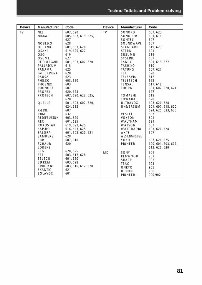
81
Techno Tidbits and Problem-solving
Device
TV
Manufacturer
NEINIKKAI
NOBLIKOOCEANICOSAKIOSOOSUMEOTTO VERSANDPALLADIUMPANAMAPATHO CINEMAPAUSAPHILCOPHOENIXPHONOLAPROFEXPROTECH
QUELLE
R-LINERBMREDIFFUSIONREXROADSTARSAISHOSALORASAMBERSSBRSCHAUBLORENZSEGSEISELECOSIAREMSINUDYNESKANTICSOLAVOX
Code
607, 620605, 607, 619, 625,627628601, 603, 620619, 625, 627619627601, 603, 607, 620615625620623603, 620603607620, 623607, 620, 623, 625,628601, 603, 607, 620,624, 632607632603, 620601, 625619, 623, 625616, 623, 625601, 603, 620, 621628607, 610620
620, 625603, 617, 628601, 620603, 628603, 616, 617, 628621601
Device
TV
MD
Manufacturer
SONOKOSONOLORSONTECSOUNDWAVESTANDARDSTERNSUSUMUSYSLINETANDYTASHIKOTATUNGTECTELEAVIATELETECHTENSAITHORN
TOMASHITOWADAULTRAVOXUNIVERSUM
VESTELVOXSONWALTHAMWATSONWATT RADIOWHITEWESTINGHOUSEYOKOPIONEER
SONYKENWOODSHARPTEACONKYODENONPIONEER
Code
607, 623601, 611607607619, 623601619607601, 619, 627610607, 627620612623617, 619601, 607, 620, 624,627618620603, 620, 628601, 607, 615, 620,624, 625, 633, 635607601621607603, 620, 628607
607, 620, 625600, 601, 603, 607,612, 620, 630
901903902904905906900,902
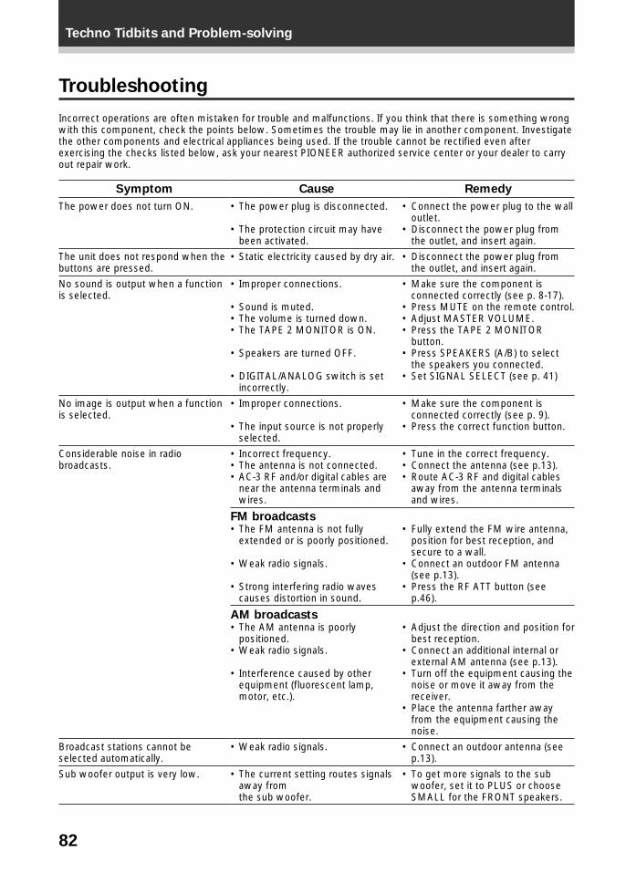
82
Techno Tidbits and Problem-solving
Troubleshooting
Incorrect operations are often mistaken for trouble and malfunctions. If you think that there is something wrongwith this component, check the points below. Sometimes the trouble may lie in another component. Investigatethe other components and electrical appliances being used. If the trouble cannot be rectified even afterexercising the checks listed below, ask your nearest PIONEER authorized service center or your dealer to carryout repair work.
Symptom
The power does not turn ON.
The unit does not respond when thebuttons are pressed.
No sound is output when a functionis selected.
No image is output when a functionis selected.
Considerable noise in radiobroadcasts.
Broadcast stations cannot beselected automatically.
Sub woofer output is very low.
Cause
• The power plug is disconnected.
• The protection circuit may havebeen activated.
• Static electricity caused by dry air.
• Improper connections.
• Sound is muted.• The volume is turned down.• The TAPE 2 MONITOR is ON.
• Speakers are turned OFF.
• DIGITAL/ANALOG switch is setincorrectly.
• Improper connections.
• The input source is not properlyselected.
• Incorrect frequency.• The antenna is not connected.• AC-3 RF and/or digital cables are
near the antenna terminals andwires.
FM broadcasts• The FM antenna is not fully
extended or is poorly positioned.
• Weak radio signals.
• Strong interfering radio wavescauses distortion in sound.
AM broadcasts• The AM antenna is poorly
positioned.• Weak radio signals.
• Interference caused by otherequipment (fluorescent lamp,motor, etc.).
• Weak radio signals.
• The current setting routes signalsaway fromthe sub woofer.
Remedy
• Connect the power plug to the walloutlet.
• Disconnect the power plug fromthe outlet, and insert again.
• Disconnect the power plug fromthe outlet, and insert again.
• Make sure the component isconnected correctly (see p. 8-17).
• Press MUTE on the remote control.• Adjust MASTER VOLUME.• Press the TAPE 2 MONITOR
button.• Press SPEAKERS (A/B) to select
the speakers you connected.• Set SIGNAL SELECT (see p. 41)
• Make sure the component isconnected correctly (see p. 9).
• Press the correct function button.
• Tune in the correct frequency.• Connect the antenna (see p.13).• Route AC-3 RF and digital cables
away from the antenna terminalsand wires.
• Fully extend the FM wire antenna,position for best reception, andsecure to a wall.
• Connect an outdoor FM antenna(see p.13).
• Press the RF ATT button (seep.46).
• Adjust the direction and position forbest reception.
• Connect an additional internal orexternal AM antenna (see p.13).
• Turn off the equipment causing thenoise or move it away from thereceiver.
• Place the antenna farther awayfrom the equipment causing thenoise.
• Connect an outdoor antenna (seep.13).
• To get more signals to the subwoofer, set it to PLUS or chooseSMALL for the FRONT speakers.
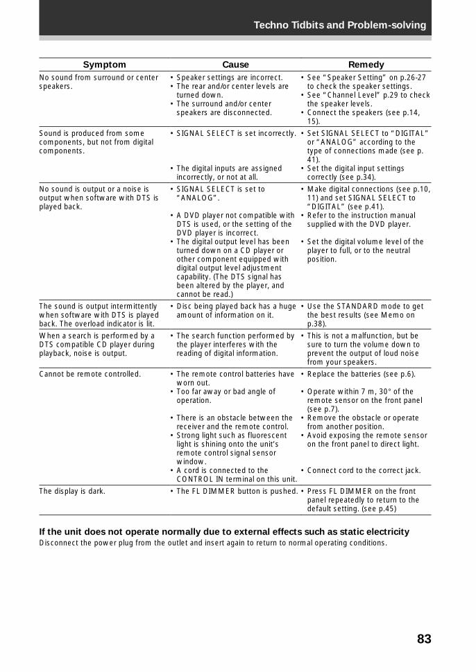
83
Techno Tidbits and Problem-solving
Symptom
No sound from surround or centerspeakers.
Sound is produced from somecomponents, but not from digitalcomponents.
No sound is output or a noise isoutput when software with DTS isplayed back.
The sound is output intermittentlywhen software with DTS is playedback. The overload indicator is lit.
When a search is performed by aDTS compatible CD player duringplayback, noise is output.
Cannot be remote controlled.
The display is dark.
Cause
• Speaker settings are incorrect.• The rear and/or center levels are
turned down.• The surround and/or center
speakers are disconnected.
• SIGNAL SELECT is set incorrectly.
• The digital inputs are assignedincorrectly, or not at all.
• SIGNAL SELECT is set to“ANALOG”.
• A DVD player not compatible withDTS is used, or the setting of theDVD player is incorrect.
• The digital output level has beenturned down on a CD player orother component equipped withdigital output level adjustmentcapability. (The DTS signal hasbeen altered by the player, andcannot be read.)
• Disc being played back has a hugeamount of information on it.
• The search function performed bythe player interferes with thereading of digital information.
• The remote control batteries haveworn out.
• Too far away or bad angle ofoperation.
• There is an obstacle between thereceiver and the remote control.
• Strong light such as fluorescentlight is shining onto the unit’sremote control signal sensorwindow.
• A cord is connected to theCONTROL IN terminal on this unit.
• The FL DIMMER button is pushed.
Remedy
• See “Speaker Setting” on p.26-27to check the speaker settings.
• See “Channel Level” p.29 to checkthe speaker levels.
• Connect the speakers (see p.14,15).
• Set SIGNAL SELECT to “DIGITAL”or “ANALOG” according to thetype of connections made (see p.41).
• Set the digital input settingscorrectly (see p.34).
• Make digital connections (see p.10,11) and set SIGNAL SELECT to“DIGITAL” (see p.41).
• Refer to the instruction manualsupplied with the DVD player.
• Set the digital volume level of theplayer to full, or to the neutralposition.
• Use the STANDARD mode to getthe best results (see Memo onp.38).
• This is not a malfunction, but besure to turn the volume down toprevent the output of loud noisefrom your speakers.
• Replace the batteries (see p.6).
• Operate within 7 m, 30° of theremote sensor on the front panel(see p.7).
• Remove the obstacle or operatefrom another position.
• Avoid exposing the remote sensoron the front panel to direct light.
• Connect cord to the correct jack.
• Press FL DIMMER on the frontpanel repeatedly to return to thedefault setting. (see p.45)
If the unit does not operate normally due to external effects such as static electricity
Disconnect the power plug from the outlet and insert again to return to normal operating conditions.
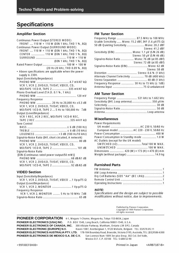
Techno Tidbits and Problem-solving
Published by Pioneer Corporation.Copyright © 1999 Pioneer Corporation.All rights reserved.
Printed in Japan <ARB7187-B><99F00EF0H00>
Specifications
FM Tuner Section
Frequency Range ......................... 87.5 MHz to 108 MHzUsable Sensitivity ...... Mono: 15.2 dBf, IHF (1.6 µV/75 Ω)50 dB Quieting Sensitivity ....................... Mono: 20.2 dBf
Stereo: 41.2 dBfSensitivity (DIN) ...................... Mono: 1.1 µV (S/N 26 dB)
Stereo: 50 µV (S/N 46 dB)Signal-to-Noise Ratio ................. Mono: 76 dB (at 85 dBf)
Stereo: 72 dB (at 85 dBf)Signal-to-Noise Ratio (DIN) .......................... Mono: 62 dB
Stereo: 58 dBDistortion ...................................... Stereo: 0.6 % (1 kHz)Alternate Channel Selectivity ................. 70 dB (400 kHz)Stereo Separation ...................................... 40 dB (1 kHz)Frequency Response ................ 30 Hz to 15 kHz (± 1dB)Antenna Input ....................................... 75 Ω unbalanced
AM Tuner Section
Frequency Range .......................... 531 kHz to 1.602 kHzSensitivity (IHF, Loop antenna) ......................... 350 µV/mSelectivity ............................................................... 30 dBSignal-to-Noise Ratio .............................................. 50 dBAntenna ...................................................... Loop antenna
Miscellaneous
Power RequirementsUK model ...................................... AC 230 V, 50/60 HzEuropean model ................... AC 220 - 230 V, 50/60 Hz
Power Consumption ............................................. 400 WPower Consumption in Standby mode .................. 1.0 WAC Outlets (except for the UK model)
SWITCHED (×2) ............................... Total 100 W MAX.UNSWITCHED ........................................ 100 W MAX.
Dimensions .................. 420 (W) × 173 (H) × 470 (D) mmWeight (without package) .................................... 14.9 kg
Furnished Parts
FM Antenna ................................................................... 1AM Loop Antenna .......................................................... 1Dry Cell Batteries (SIZE “AA” (IEC LR6)) ....................... 2Remote Control Unit ...................................................... 1Operating Instructions ................................................... 1
NOTE:Specifications and the design are subject to possiblemodifications without notice, due to improvements.
Amplifier Section
Continuous Power Output (STEREO MODE)FRONT .... 110 W + 110 W (DIN 1 kHz, THD 1 %, 8Ω)
Continuous Power Output (SURROUND MODE)FRONT .... 110 W + 110 W (DIN 1 kHz, THD 1 %, 8Ω)CENTER ................. 110 W (DIN 1 kHz, THD 1 %, 8Ω)SURROUND ....................................... 110 W + 110 W
(DIN 1 kHz, THD 1 %, 8Ω)Rated Power Output .............................. 100 W + 100 W
(20 Hz-20 kHz, THD 0.09 %, 8Ω)• Above specifications are applicable when the power
supply is 230V.Input (Sensitivity/Impedance)
PHONO MM .......................................... 4.7 mV/47 kΩVCR 1, VCR 2, DVD/LD, TV/SAT, VIDEO, CD,MD/TAPE 1/CD-R, TAPE 2 ..................... 335 mV/47 kΩ
Phono Overload Level (T.H.D. 0.1 %, 1 kHz)PHONO MM ................................................... 120 mV
Frequency ResponsePHONO MM ................... 20 Hz to 20,000 Hz ±0.3 dBVCR 1, VCR 2, DVD/LD, TV/SAT, VIDEO, CD,MD/TAPE 1/CD-R, TAPE 2 .... 5 Hz to 100,000 Hz dB
Output (Level/Impedance)VCR 1 REC, VCR 2 REC, MD/TAPE 1/CD-R REC,TAPE 2 REC ............................................. 335 mV/1 kΩ
Tone ControlBASS ................................................... ± 6 dB (100 Hz)TREBLE ............................................... ± 6 dB (10 kHz)LOUDNESS .............................. +3 dB (100 Hz/10 kHz)
Signal-to-Noise Ratio (IHF, short circuited, A network)PHONO MM ...................................................... 80 dBVCR 1, VCR 2, DVD/LD, TV/SAT, VIDEO, CD,MD/TAPE 1/CD-R, TAPE 2 ................................ 101 dB
Signal-to-Noise Ratio [DIN (Continuous rated power output/50 mW)]
PHONO MM ............................................ 68 dB/61 dBVCR 1, VCR 2, DVD/LD, TV/SAT, VIDEO, CD,MD/TAPE 1/CD-R, TAPE 2 ........................ 92 dB/65 dB
VIDEO Section
Input (Sensitivity/Impedance)VCR 1, VCR 2, DVD/LD, TV/SAT, VIDEO ... 1 Vp-p/75 Ω
Output (Level/Impedance)VCR 1, VCR 2, MONITOR ......................... 1 Vp-p/75 Ω
Frequency Response VCR 1, VCR 2, MONITOR ......... 5 Hz to 10 MHz dB
Signal-to-Noise Ratio .............................................. 65 dB
+0–3
+0–3
PIONEER CORPORATION 4-1, Meguro 1-Chome, Meguro-ku, Tokyo 153-8654, Japan
PIONEER ELECTRONICS [USA] INC. P.O. BOX 1540, Long Beach, California 90801-1540, U.S.A.PIONEER ELECTRONICS OF CANADA, INC. 300 Allstate Parkway, Markham, Ontario L3R OP2, CanadaPIONEER ELECTRONIC [EUROPE] N.V. Haven 1087, Keetberglaan 1, 9120 Melsele, Belgium TEL: 03/570.05.11PIONEER ELECTRONICS AUSTRALIA PTY. LTD. 178-184 Boundary Road, Braeside, Victoria 3195, Australia, TEL: [03] 9586-6300PIONEER ELECTRONICS DE MEXICO S.A. DE C.V. San Lorenzo Num 1009 3er piso Desp. 302 Col. Del Valle,
Mexico D.F. C.P. 03100 TEL: 5-688-52-90