Embed Size (px)
Citation preview

August 2016
CONTINUOUSLY REINFORCED CONCRETE PAVEMENT MANUAL
Guidelines for Design, Construction, Maintenance, and Rehabilitation
FHWA-HIF-16-026

i
Authors
Jeffery R. Roesler, Ph.D., P.E. University of Illinois at Urbana-Champaign
Jacob E. Hiller, Ph.D.Michigan Technological University
Alexander S. Brand, Ph.D.University of Illinois at Urbana-Champaign

ii
ACKNOWLEDGEMENTS
This manual was produced for the Federal Highway Administration (FHWA) under a cooperative agreement with the Concrete Reinforcing Steel Institute (CRSI). The manual was reviewed and edited for publication by Samuel Tyson, P.E., Federal Highway Administration, and Greg Halsted, P.E., Concrete Reinforcing Steel Institute, with assistance from Shiraz Tayabji, Ph.D., P.E., Advanced Concrete Consultancy LLC.

iii

iv
PREFACE
Continuously reinforced concrete pavement (CRCP) was introduced in the United States almost 100 years ago when the U.S. Bureau of Public Roads (now the Federal Highway Administration) constructed a CRCP test section on Columbia Pike in Arlington, Virginia. Since then, CRCP has been constructed in many states in the U.S. and in a number of other countries. As experience with the design and construction of CRCP has grown, a variety of lessons learned through practical experience and research have contributed to the development of best practices for CRCP throughout its life cycle.
Today, CRCP is designed and constructed as a pavement of choice for long-life performance, recognizing that initial smoothness will be maintained for decades and that maintenance during that time will be minimal. This manual provides guidance for materials selection and quality assurance, and for the mechanistic-empirical design, construction, maintenance, and rehabilitation of CRCP. Case studies are summarized to document the overall long-life performance of CRCP in the U.S. and in other countries.

v
TABLE OF CONTENTS
PREFACE.......................................................................................................................iv
TABLE OF CONTENTS...................................................................................................v
LIST OF FIGURES........................................................................................................vii
LIST OF TABLES.............................................................................................................x
CHAPTER 1: INTRODUCTION AND OVERVIEW...........................................................1
What is CRCP?....................................................................................................2 When and Why is CRCP Used?..........................................................................3 Overview of Key Points for CRCP.....................................................................4 CRCP Design Overview.....................................................................................5 CRCP Manual Objectives..................................................................................5 Scope of the CRCP Manual...............................................................................5
CHAPTER 2: CRCP DESIGN FUNDAMENTALS.............................................................7
CRCP Behavior...................................................................................................8 CRCP Performance Indicators and Distress Types .......................................10
CHAPTER 3: CRCP STRUCTURAL DESIGN.................................................................15
CRCP Design Methods ....................................................................................16 CRCP Main Design Inputs and Features........................................................20 Best Practices for Selecting CRCP Thickness................................................27 AASHTO Pavement ME Design Input Sensitivity..........................................28 Composite Pavements and CRCP...................................................................31 Life Cycle Cost Analysis and Assessment of CRCP.........................................32
CHAPTER 4: REINFORCEMENT DESIGN AND DETAILS............................................33
Characteristics of Reinforcing Steel..............................................................34 Longitudinal Reinforcement..........................................................................35 Transverse Reinforcement.............................................................................39
CHAPTER 5: CRCP CONSTRUCTION...........................................................................43
Reinforcement Placement.............................................................................44 Paving..............................................................................................................47 Construction Traffic Management.................................................................52 Joints................................................................................................................52 Crossovers.......................................................................................................60 Shoulders, Ramps, and Intersections............................................................62 Construction Techniques for Controlling Crack Spacing.............................66 Inspection........................................................................................................66

vi
CHAPTER 6: CRCP PERFORMANCE...........................................................................69
CRCP Experience in the U.S............................................................................70 International CRCP Experience......................................................................73 LTPP Program Data.........................................................................................76
CHAPTER 7: CRCP RESTORATION AND RESURFACING...........................................77
Condition Assessment....................................................................................79 Overview of Maintenance and Repair Techniques.......................................81 Overlays on CRCP............................................................................................88 Reconstruction...............................................................................................92
CHAPTER 8: USE OF CRCP AS AN OVERLAY..............................................................95
Unbonded and Bonded CRCP Overlays........................................................96 Structural Design of CRCP Overlays..............................................................97
CHAPTER 9: GUIDE SPECIFICATION FOR CRCP........................................................99
Introduction.................................................................................................100 Guide Specification......................................................................................100 Sources..........................................................................................................105
APPENDIX A: GLOSSARY..........................................................................................107
APPENDIX B: REFERENCES......................................................................................115

vii
LIST OF FIGURES
Figure 1. The three common concrete pavement types........................................................................................................................2
Figure 2. Newly constructed CRCP (Virginia).....................................................................................................................................3
Figure 3. Reinforcement design and placement is critical for good performance...........................................................................4
Figure 4. Concrete mixture design and materials are critical for good performance......................................................................4
Figure 5. A typical CRCP cross-section.................................................................................................................................................5
Figure 6. Schematic of several factors influencing CRCP behavior...................................................................................................9
Figure 7. A typical CRCP punchout distress.......................................................................................................................................10
Figure 8. Schematic of CRCP punchout mechanism.........................................................................................................................12
Figure 9. Spalling along transverse crack in a CRCP..........................................................................................................................13
Figure 10. Horizontal cracking plane in CRCP...................................................................................................................................14
Figure 11. Structural performance in terms of punchouts as a function of time or traffic loads.................................................17
Figure 12. Functional performance in terms of IRI as a function of time or traffic loads............................................................17
Figure 13. Framework of mechanistic-empirical design procedure for CRCP...............................................................................19
Figure 14. Impact of PCC thickness changes on predicted CRCP punchouts and terminal IRI.................................................29
Figure 15. Impact of reinforcing steel percentage on predicted CRCP punchouts and terminal IRI.........................................29
Figure 16. Impact of steel depth (0.7 percent) on predicted CRCP punchouts and terminal IRI...............................................29
Figure 17. Impact of shoulder type on predicted CRCP punchouts and terminal IRI.................................................................30
Figure 18. Impact of base type and associated friction on predicted CRCP punchouts and terminal IRI.................................30
Figure 19. Impact of construction month on predicted CRCP punchouts and terminal IRI......................................................31
Figure 20. Example of the ASTM marking requirements for a #11, Grade 60 bar (from CRSI).................................................34
Figure 21. Mill and coating certifications for reinforcing steel.........................................................................................................35
Figure 22. Steel placed on ATB (Virginia)...........................................................................................................................................35
Figure 23. Two-layer steel reinforcement mat....................................................................................................................................38
Figure 24. Lap splices.............................................................................................................................................................................38
Figure 25. Typical layout pattern for longitudinal steel with laps skewed across pavement.........................................................38

viii
Figure 26. Typical lap-splice patterns (skewed and staggered) for longitudinal steel ...................................................................39
Figure 27. Planned location and tie bars for saw-cut longitudinal joint.........................................................................................40
Figure 28. Longitudinal construction joint with tie bars.................................................................................................................40
Figure 29. Two-piece threaded tie bars for longitudinal construction joint...................................................................................40
Figure 30. Worker inspecting longitudinal reinforcing steel with transverse bars and chairs (Virginia)...................................45
Figure 31. Steel placed on chairs (Texas)............................................................................................................................................45
Figure 32. Two layers of steel placed on chairs (Texas).....................................................................................................................45
Figure 33. Steel placed on transverse bar assemblies (Illinois)........................................................................................................46
Figure 34. Transverse bar assembly (TBA)........................................................................................................................................46
Figure 35. Placing longitudinal steel on TBAs...................................................................................................................................46
Figure 36. Slip-form paving of CRCP (Illinois).................................................................................................................................47
Figure 37. High-speed belt discharge of concrete from end-dump truck (Virginia)....................................................................47
Figure 38. Application of curing compound on slip-formed CRCP...............................................................................................48
Figure 39. Applying transverse tining on a new CRCP....................................................................................................................49
Figure 40. Transversely tined fresh concrete on a new CRCP.........................................................................................................49
Figure 41. Longitudinal construction joint tied with two-piece tie bars.......................................................................................53
Figure 42. Longitudinal (hinged) contraction joint..........................................................................................................................53
Figure 43. Longitudinal free joint......................................................................................................................................................54
Figure 44. Wooden panels temporarily placed to facilitate removal of concrete carried over end-of-day header...................54
Figure 45. Finishing concrete at end-of-day header..........................................................................................................................54
Figure 46. Transverse header joint with additional reinforcement in wheel path........................................................................55
Figure 47. Transition from CRCP using a sleeper slab and a wide-flange I-beam........................................................................56
Figure 48. Transition from CRCP using a modified wide flange.....................................................................................................57
Figure 49. Transition from CRCP using doweled joints...................................................................................................................57
Figure 50. Transition from CRCP using reduced longitudinal steel content with saw-cuts and doweled joints......................58
Figure 51. Transition between CRCP and asphalt pavement using a tapered concrete slab.......................................................58

ix
Figure 52. Transition between CRCP and asphalt pavement using an elastomeric seal..............................................................59
Figure 53. Seamless pavement for transitions of CRCP to and from bridges..............................................................................59
Figure 54. CRCP block-out schematic...............................................................................................................................................60
Figure 55. Layout of reinforcement in leave-out section..................................................................................................................61
Figure 56. Recommended layouts for ramp connections.................................................................................................................64
Figure 57. Jointing details for ramp connections...............................................................................................................................64
Figure 58. Design details for intersection of two CRCP alignments (Texas).................................................................................65
Figure 59. Longitudinal reinforcement lap splices and ties ..............................................................................................................67
Figure 60. Lateral spacing of longitudinal steel..................................................................................................................................67
Figure 61. Checking for position and movement of longitudinal steel...........................................................................................67
Figure 62. Probing fresh concrete to check the depth of longitudinal steel....................................................................................67
Figure 63. Construction of the 1947 Vandalia CRCP test sections (Illinois)..................................................................................71
Figure 64. Construction of two-lift CRCP using two slip-form pavers on the A13 roadway (Belgium)....................................74
Figure 65. GFRP longitudinal reinforcement for CRCP (Canada)..................................................................................................75
Figure 66. Decision tree for assessing the need for restoration or resurfacing...............................................................................78
Figure 67. Full-depth and partial-depth saw-cuts made in CRCP prior to concrete removal .....................................................85
Figure 68. New steel in FDR tied to longitudinal reinforcement protruding from CRCP............................................................85
Figure 69. Full-depth and partial-depth saw-cuts at boundaries of CRCP repair area.................................................................86
Figure 70. Longitudinal steel exposed in CRCP ready for splicing with new reinforcing steel...................................................86
Figure 71. New steel in FDR spliced to longitudinal steel exposed in CRCP.................................................................................86
Figure 72. Completed FDR in CRCP...................................................................................................................................................86
Figure 73. Tie bars drilled into existing CRCP for splicing with new reinforcement in FDR (Texas)........................................87
Figure 74. Jointed concrete with dowels used for FDR of CRCP (South Carolina)......................................................................87
Figure 75. Cross-stitching a longitudinal crack..................................................................................................................................88
Figure 76. Slot-stitching a longitudinal crack with tie bars to stabilize and provide load transfer..............................................89
Figure 77. Unbonded CRCP overlay under construction..................................................................................................................97

x
LIST OF TABLES
Table 1. Structural Adequacy of CRCP based on Number of Medium and High Severity Punchouts.......................................12
Table 2. Allowable Steel Working Stress, ksi (MPa)...........................................................................................................................18
Table 3. Weight and Dimensions of ASTM Standard Reinforcing Steel Bars.................................................................................22
Table 4. ASTM Standard Grades for Reinforcing Steel Bars.............................................................................................................23
Table 5. Recommended Frictional Coefficients for CRCP Base Types by AASHTO Pavement ME..........................................25
Table 6. Composite CRCP Exhibiting Good Performance................................................................................................................31
Table 7. Reinforcement Spacing Recommendations..........................................................................................................................37
Table 8. Maintenance and Repair Techniques for CRCP Structural and Functional Distresses..................................................82
Table 9. Example of Trigger and Limit Values for Diamond Grinding............................................................................................83
Table 10. Constructability, Performance, and Cost-Effectiveness of BCO, UBCOL, and AC Overlays of CRCP......................90
Table 11. Summary of Unbonded CRCP Overlays in Illinois...........................................................................................................97

1
CHAPTER 1 INTRODUCTION AND OVERVIEW

2
WHAT IS CRCP?
Continuously reinforced concrete pavement (CRCP) contains continuous, longitudinal steel reinforcement without transverse joints, except where required for end-of-day header joints, at bridge approaches, and at transitions to other pavement structures. Continuous reinforcement is a strategy for managing the transverse cracking that occurs in all new concrete pavements. In new concrete pavements, volumetric changes caused by cement hydration, thermal effects, and external drying are restrained by the pavement base layer and longitudinal reinforcement causing tensile stresses to develop in the concrete. These stresses, referred to as restraint stresses, increase more rapidly than the strength of the concrete at early ages of the concrete pavement, so, at some point, full-depth transverse cracks form, dividing the pavement into short, individual slabs. In CRCP, the continuous reinforcement results in internal restraint and produces transverse cracks that are closely spaced with small crack widths that help to maximize the aggregate interlock between adjacent CRCP panels. This feature is different from jointed plain concrete pavements (JPCP), where the number and location of transverse cracks are typically managed by timely sawing. In CRCP, the shorter panel sizes and high load transfer between adjacent CRCP panels reduce the flexural (bending) stresses from traffic loads and temperature and moisture curling. A third type, jointed reinforced concrete pavement (JRCP), incorporates wire mesh reinforcement equaling about 0.2 percent of the cross-sectional area of the concrete; however, it is no longer widely used for highway pavements in the U.S. The basic features of these three concrete pavement types are shown in Figure 1.
Figure 1. The three common concrete pavement types.

3
WHEN AND WHY IS CRCP USED?
Continuously reinforced concrete is an excellent long-life pavement solution for highly-trafficked and heavily-loaded roadways, such as interstate highways (Figure 2). Well-designed and well-constructed CRCPs accomplish the following objectives:
• Eliminate joint-maintenance costs for the life of the pavement, helping meet the public’s desire for reduced work zones and related travel delays.
• Provide long-term, high load transfer across the transverse cracks, resulting in a consistently smooth and quiet ride with less distress development at the cracks than jointed pavements.
CRCP can be expected to provide over 40 years of exceptional performance with minimal maintenance when properly designed and constructed. These attributes are becoming increasingly important in high-traffic, heavy-truck areas, where delays are costly and a smooth ride is expected. Some of the most highly trafficked corridors in the country including I-75 in Atlanta, I-90 and I-94 in Chicago, and I-45 in Houston have demonstrated the reliable, low-maintenance performance of CRCP.
Data from the Federal Highway Administration’s (FHWA’s) Long Term Pavement Performance (LTPP) program show that the large majority of heavily-trafficked sections of CRCP projects in 22 states have maintained their smoothness for at least 20 to 30 years. CRCP can be easily widened to provide additional capacity and, after many years of service, can be successfully overlaid with either concrete or asphalt.
Figure 2. Newly constructed CRCP (Virginia).

4
OVERVIEW OF KEY POINTS FOR CRCP
Several states, such as Illinois and Texas, have refined their CRCP design and construction techniques, resulting in lower life-cycle costs and increased road-user satisfaction. The following is a brief list of key practices that help ensure successful CRCP projects:
• Structural design, concrete mixture proportioning, and construction decisions and practices (Figure 3 and Figure 4) should maximize load-transfer efficiency across cracks and minimize slab flexural stresses.
• Cracks that are closely spaced [3.0 to 4.0 ft (0.9 to 1.2 m) maximum is optimum] and tight [less than 0.02 in (0.5 mm) at the depth of the reinforcement] help maximize load-transfer efficiency and minimize flexural stresses, maintaining steel stress well below the yield strength.
• Closely spaced, tight cracks result when the project includes:• Adequate longitudinal steel content (typical mini-
mum of 0.7 percent of the slab cross-section area). • Optimum reinforcement bar diameter and spacing. • Proper lapping of reinforcement splices. • Proper depth of reinforcement placement.
• Reinforcement design has to consider excessive plastic deformation. Stress in the reinforcement is usually limited to a reasonable percentage of the yield strength to limit the amount of plastic deformation and avoid fracture.
• Larger-sized, abrasion-resistant aggregates promote good aggregate interlock and thus enhance load-transfer efficiency.
• Thorough consolidation of concrete around the reinforcement to promote long-term bonding.
• Sufficient slab thickness is required to manage transverse tensile stresses because of truck loading and curling.
• The foundation layers must be uniform and stable, provide good drainage, and extend beyond the slab edge through the shoulder area and through transitions at bridge approaches, cuts, and fills.
• Base layer below the CRCP should be erosion resistant.
• Edge support provided by widened lane or tied concrete shoulders can improve CRCP performance by reducing bending stresses from heavily-loaded axles.
• Longitudinal construction joints must be tied to adjacent lanes or shoulder slabs.
• Curing should be actively managed for each CRCP application, weather conditions, materials, etc., to achieve desired transverse crack spacing and crack width as well as concrete strength and quality.
Many practices listed above are illustrated in Figure 5, which shows a typical modern CRCP cross-section for new construction. Ongoing research, field monitoring, and materials innovations will likely result in additional refinements to these practices.
Figure 3. Reinforcement design and placement is critical for good performance. Figure 4. Concrete mixture design and materials are critical for good performance.

5
CRCP DESIGN OVERVIEW
A 2001 survey on CRCP design practices in the US indicated that most states commonly used the American Association of State Highway and Transportation Officials (AASHTO) design procedure published in 1986 (and later in 1993). One exception was Illinois, which used a modified version of this method.[2,3] However, the standard for design of CRCP has recently undergone significant changes from the 1993 AASHTO Pavement Design Guide, namely the completion of the Mechanistic–Empirical Pavement Design Guide (MEPDG)[4] and recent availability of the software designated as “AASHTOWare® Pavement ME Design.” Interested readers can review publications that document findings that have led to the current use of CRCP as a long-life and cost-effective pavement solution. These publications include an FHWA research study of CRCP sections in several states;[5-11] the evaluation of CRCP sections in the LTPP database;[12-13] and other experimental and field studies from around the world.[14-16]
CRCP MANUAL OBJECTIVES
This manual is intended to provide the most current guidelines on the design, construction, maintenance, and rehabilitation of CRCP. These guidelines primarily address CRCP structural design, use of reinforcement, construction practices, and repair and rehabilitation of existing CRCP. Guidance is included on the selection of design inputs, pavement performance criteria, recommendations for different CRCP structural features, and best practices for construction, maintenance, and rehabilitation.
SCOPE OF THE CRCP MANUAL
The remainder of this CRCP manual is divided into the following chapters:
• Chapters 2 and 3 discuss CRCP design fundamentals and inputs, the mechanistic-empirical pavement design method, design sensitivity, and structural and functional performance criteria.
Figure 5. A typical CRCP cross-section.

6
• Chapter 4 presents steel reinforcement design and details.
• Chapter 5 is an overview of the CRCP construction process, including placement of reinforcement, concrete placement, inspection, and maintenance of traffic during construction, and CRCP details related to shoulders, intersections, roundabouts, transition joints, ramps, and crossovers.
• Chapter 6 provides a brief summary of CRCP performance.
• Chapters 7 and 8 present maintenance, repair, and rehabilitation techniques for existing CRCP.
• Chapter 9 provides a sample guide specification for CRCP that highway agencies can utilize to make it easier to implement the design and construction of CRCP.
• Appendix A provides a glossary of terms.• Appendix B provides a list of references.

7
CHAPTER 2 CRCP DESIGN FUNDAMENTALS

8
Designing a CRCP involves developing details for the different geometric pavement features such as thickness, longitudinal and transverse reinforcement, construction joints, slab width, shoulders, and pavement transitions based on site-specific traffic, climatic, and foundation parameters. The designer selects parameters that will be suitable to achieve the desired performance level for the design period selected. The goal is to use locally available materials to the greatest extent possible without compromising pavement performance.
The crack spacing, crack width, steel stress, and bond development length generated as a function of reinforcement, base restraint and climatic conditions all affect the CRCP structural integrity in the long term. During the CRCP planning and design stages, it is important to carefully analyze the CRCP structural design, selected materials, and the construction process so that an optimal transverse cracking pattern develops, which in turn minimizes the development of premature pavement distress.
It should also be noted that many of the design aspects described herein are common to all concrete pavements, not just CRCP. As a result, and for brevity, some aspects of concrete pavement design will not be expanded upon in this manual. Instead, guidance should be sought from the appropriate design references such as AASHTO standards and highway agency specifications.
The following sections provide a description of the factors affecting crack patterns that develop in early-age CRCP and further discuss the impact that this CRCP behavior has on pavement performance. Also given is additional information on structural and functional performance factors and distress types.
CRCP BEHAVIOR
Following construction of a CRCP, a number of mechanisms influence development of stresses in the slab and ultimately, the formation of cracks. Figure 6 provides a schematic representation of several factors influencing CRCP behavior. During early ages after concrete placement, temperature and moisture changes produce volume changes in the concrete that are restrained by reinforcement, base friction, and adjacent lanes, leading to the development of internal stresses in both the concrete slab and the longitudinal steel reinforcement. Since concrete is weak in tension, whenever the developed concrete slab stresses are higher than the tensile strength of the concrete, transverse cracks form to relieve the stresses. Reinforcement serves to keep these transverse crack widths small, which is essential in maintaining the high load transfer provided through aggregate interlock. This, in turn, reduces tensile stresses in the concrete slab due to high and heavy traffic loadings.
Tight transverse cracks also help to minimize water infiltration and intrusion of incompressible materials. Significant reductions in slab temperature from the time of setting as well as long-term drying shrinkage of the concrete result in ongoing cracking and a reduction in mean transverse crack spacing over time. Tensile stresses from repeated wheel load applications and seasonal temperature changes further reduce the crack spacing over time, but at a much slower rate. Overall, it has been observed that the transverse crack spacing decreases rapidly during the early age of the CRCP, up until about one or two years. After this stage, the transverse cracking pattern remains relatively constant until the slab reaches the end of its fatigue life.
The primary early-age pavement indicators of CRCP performance include crack spacing, crack width, and steel stress. The following sections describe these indicators in more detail.

9
Crack Spacing
CRCP slab segments distribute traffic loads in the longitudinal and transverse directions. In the case of short transverse crack spacing with lower load transfer, however, the slab can act more as a beam with its longer dimension in the transverse direction. Significant transverse flexural stresses due to traffic loading can then develop. As a result, longitudinal cracks may subsequently form, progressing into a distress condition commonly known as a punchout (illustrated in Figure 7). To minimize CRCP distresses, the 2008 AASHTO manual recommended crack spacing at 3 to 6 ft (0.9 to 1.8 m).[4] Because of variability, it is also recommended that crack spacing be characterized in terms of both its average value and its distribution. For a given crack spacing distribution, the percentage of crack spacing that falls outside the recommended range should be determined, as this may be more indicative of the potential for distress during the pavement life. An analysis of several LTPP sections has shown a higher probability of punchouts when average crack spacing is less than 3 ft (1.0 m).[18] However, CRCP with a crack spacing of less than 2 ft
(0.6 m) has performed well under good base-soil-support conditions and narrow crack widths. Although the designer has some control over the crack pattern through the specified quantity of reinforcement, there are confounding factors that cannot be as readily controlled during the design stage. These include the in-situ concrete strength, climatic conditions during construction, and construction practices. Therefore, it is important that the highway agency ensure that the assumptions made during design are adhered to during the materials selection and construction processes. This is accomplished through the development and enforcement of sound specifications or special provisions.
With respect to crack spacing, cases of cluster cracking, divided cracks, and Y-cracking are unique aspects of short crack spacing that can be problematic in terms of their contribution to localized failures including punchouts. These types of cracking are generally more associated with certain inadequate construction activities such as localized weak support, variable slab-base friction, inadequate concrete consolidation, and/or variation in the quality of concrete curing.
Figure 6. Schematic of several factors influencing CRCP behavior.

10
Crack Width
Crack width has a critical effect on CRCP performance in several ways. Excessive crack widths may lead to undesirable conditions such as lower aggregate interlock (load transfer) between adjacent CRCP panels and infiltration of water that could later result in weakening of the support layers, erosion of the base layer, or corrosion of the reinforcing steel. Additionally, incompressible materials can enter into wide cracks and lead to excessive bearing stresses at the transverse cracks, increasing the potential for spalling. A reduction in load transfer across the transverse cracks leads to an increase in both slab deflections and tensile stresses that can result in a higher probability of spalling, faulting, secondary cracking, and/or punchouts.
The AASHTO-86/93 Guide recommended limiting the crack width to 0.04 in (1 mm) at the pavement surface to avoid spalling.[3] However, a crack width of 0.024 in (0.6 mm) or less has been found to be effective in reducing water penetration, thus minimizing corrosion of the steel and maintaining a high load transfer efficiency. [19,20] The MEPDG Manual of Practice suggests that the crack width should be less than 0.02 in (0.5 mm) at the depth of steel over the entire design period.[4] Similarly, to control crack spacing, the designer may select a reinforcement percentage to achieve a desired crack width.
In general, a higher percentage of longitudinal steel leads to smaller crack spacing and tighter crack widths. The results of field performance evaluations have found that longitudinal steel content in the range of 0.7% to 0.85% effectively keeps crack widths reasonably tight throughout the life of the CRCP.
The depth of the reinforcement is another important factor in controlling crack width. Major experiments in Illinois have shown that when reinforcement is placed above mid-depth, the cracks are more narrow at the surface, leading to fewer punchouts and repairs over the long term. For reasons of adequate cover, reinforcement should be placed at least 3.5 in (89 mm) from the surface of the CRCP but above the mid-depth of the slab.[4]
Reinforcement Stress
The level of stress that develops in both the concrete and the longitudinal reinforcement will also influence long-term CRCP performance. As stated earlier, the longitudinal reinforcement serves to restrain volume changes in the concrete, helping to induce transverse cracking, and then helping to keep cracks tight. Consequently, significant stresses develop in the reinforcement at the transverse crack locations. The reinforcement design has to consider possible fracture and/or excessive plastic deformation of the steel at these locations. Excessive yield or fracture of the reinforcement may lead to wide cracks, corrosion, and loss of load transfer that may later result in significant distresses. It is common for a limiting stress criterion to be used for reinforcement design. This is often selected as a fixed percentage of the yield strength, thus avoiding fracture, and allowing only a small probability of plastic deformation.[3,21] A reasonable allowable stress is two-thirds of the steel yield strength.[22]
CRCP PERFORMANCE INDICATORS AND DISTRESS TYPES
The following sections expand on the primary CRCP structural and functional performance indicators that are typically used as design criteria. These factors should be considered during the design stage and controlled through construction specifications. The result will be
Figure 7. A typical CRCP punchout distress.

11
a CRCP structure that is capable of accommodating the expected traffic and environmental loadings.
Pumping and ErosionPumping is the ejection of water and support material through cracks, pavement-shoulder edge joints, and longitudinal or transverse joints. Primary factors that influence pumping are the erodibility of the support layer materials,[23] the presence of free water, and slab deflections due to traffic loading. Secondary factors include the permeability of the subgrade material, CRCP crack spacing, and the quality of the lane-shoulder joint seal. Pumping leads to a loss of pavement support and the formation of voids. A void thicker than 0.05 in (1.3 mm) will cause significant deflections when loaded.[10] In the visual condition survey, pumping can be detected by looking for punchouts, lane-shoulder drop-offs, pavement roughness, and the deposit of subbase or other foundation layer materials on the pavement surface or shoulder. If pumping has progressed to the point that voids have formed, their presence can be confirmed by deflection testing or coring.
CrackingCRCP is designed to have regularly-spaced cracks in the transverse direction. These transverse cracks are expected to remain tight and are not considered distresses. However, if these cracks widen and begin to exhibit distresses such as raveling and spalling, then some restoration or rehabilitation treatment may be required. The mechanisms that cause wide transverse cracks and the development of longitudinal cracks are discussed in the following sections.
Wide Transverse Cracks Lower reinforcement contents in CRCP can cause crack spacing to develop greater than 10 ft (3 m) in some cases.[20] This larger crack spacing can lead to a widening of the transverse cracks and to an increase in tensile stress in the reinforcement. If the reinforcement yields or ruptures, then the transverse crack will be free to open and close and will lose much of its load transfer capabilities. Water will then readily infiltrate the crack. Even if the reinforcement does not rupture initially, the loss of support and associated high deflections under heavy traffic loads may eventually cause it to rupture.
Good construction practices are important to ensure steel continuity, proper lap length, and good consolidation of the concrete, especially at construction joints.
Wide transverse cracks also can form when reinforcing steel corrodes, which means that the steel reinforcing bars are more likely to rupture. Typically, the steel reinforcement ruptures first in the outer bars of the outside lane. This places more stress on the inner bars, and rupture progresses from the outside inward.[10] To minimize this occurrence, transverse crack widths should be limited to 0.02 in (0.5 mm) to prevent the infiltration of moisture, deicing salts, and incompressible materials. Medium- and high-severity transverse cracks with widths ranging from 0.12 to 0.24 in (3 to 6 mm), spalls greater than 3 in (75 mm), and faulting greater than 0.24 in (6 mm) should immediately receive full-depth repairs. As stated earlier, closely spaced, tight cracks result when the project includes adequate longitudinal steel content (a minimum of 0.7 percent of the slab cross-section area), optimum reinforcement bar diameter and spacing, proper lapping of reinforcement splices, and proper depth of reinforcement placement.
Random Longitudinal Cracks Longitudinal cracks can form in CRCP because of poor construction techniques or foundation layer settlement. Late sawcutting of longitudinal joints, or improper placement or omission of joint separator strips if used in lieu of sawing, can cause longitudinal cracks to form.[10] Longitudinal cracks of this type rarely develop further or cause additional problems if they are not within the wheel paths; however, they can be unsightly. A troublesome type of longitudinal cracking results from subgrade swelling or settlement. This type of longitudinal crack commonly widens under repeated loading, allowing water to enter the pavement structure. Treatment options for such longitudinal cracks include sealing and stitching, or complete replacement of the affected slab.
Punchouts A punchout is a type of repeated loading distress that typically occurs between closely spaced transverse cracks in CRCP. It is defined as a block or wedge of CRCP that is delimited by two consecutive transverse cracks, a longitudinal crack, and the pavement edge. A typical

12
punchout is presented in Figure 7 and commonly initiates in conjunction with erosion of the support layers between two closely spaced transverse cracks. These transverse cracks may have a larger crack width or a reduced aggregate interlock because of repeated traffic loading. Either process results in a loss of load transfer and an increase in the transverse tensile stress on the top of the slab. The longitudinal crack formation typically occurs 2 to 5 ft (0.6 to 1.5 m) from the pavement edge. Figure 8 schematically shows these key factors contributing to classic punchouts in CRCP, which are directly linked to the number of heavy repeated traffic loadings (fatigue). Progression of the punchout distress continues with cyclic traffic loading and may lead to severe faulting. Loss of support, pumping of the base material, and the reduction in load transfer across the transverse cracks are all factors in how quickly the severity of the punchout distress develops.[22] Ideally, the number of punchouts should be limited to 5 to 10 per lane-mile critical roadways, as shown in Table 1. Figure 8. Schematic of CRCP punchout mechanism.
Table 1. Structural Adequacy of CRCP based on Number of Medium and High Severity Punchouts
HighwayClassification
Number of Punchouts Per Lane-Mile
Structurally Inadequate
Marginal Structural Adequacy
Structurally Adequate
Interstate or Freeway >10 5 to 10 <5Primary >15 8 to 15 <8Secondary >20 10 to 20 <10

13
One of the most important factors in preventing punchouts is the use of a non-erodible base material (e.g., sufficiently stabilized base materials) to minimize loss of support. Evaluation of long-term performance of CRCP reveals that adequate base support with widened lanes or tied concrete shoulders provides excellent long-term CRCP performance. These and other factors that can be considered during the design stage to enhance the control of punchouts include the following:
• Adequate steel reinforcement and placement depthto maintain tight crack widths.
• Sufficient concrete strength and slab thickness toreduce tensile stresses and premature crackinggiven the known traffic loadings and repetitions.
• While any approved aggregate source can besuccessfully used in a CRCP, the selection of hardand angular aggregates with a lower coefficientof thermal expansion (CTE) can maintain highload transfer and further improve the behaviorof the transfer cracks. For example, the TexasDepartment of Transportation (TxDOT) hasperformed extensive investigations into the effectof different aggregate materials on the performanceof CRCP.[20]
• Specification of curing techniques that allow forincreased concrete hydration without excessivepeak temperatures and large losses in internalmoisture at early ages.
• Specification of mix designs that are suited for thespecific environmental conditions, i.e., limits thepeak hydration temperatures and minimizes long-term drying shrinkage of the concrete.
• Tied concrete shoulders and widened lanes.
Spalling
Spalling along transverse cracks on CRCP (Figure 9) is the result of localized fracturing of concrete that initiates as a shear delamination parallel to the surface of the CRCP at a shallow depth. Conditions linked to formation of shear delaminations include low interfacial strength between the aggregate and mortar, and moisture loss from the hydrating concrete that results in differential drying shrinkage near the CRCP surface. While these delaminations initiate early in the pavement life, they can
extend later into spalls as a result of traffic loading, the intrusion of incompressible materials, freeze-thaw cycles, and temperature fluctuations. Spalling will eventually affect the ride quality and result in a poor visual appearance of the roadway. Significant spalling is unlikely to occur if such delaminations are not formed. However, if spalling does occur, wide transverse cracks can form and blowups can develop if incompressible materials fill the crack.
Certain states such as Texas have seen spalling distress on CRCP more prevalently than others.[24,25] One spalling mechanism found in Texas relates to the type of coarse aggregates, especially those low in quartzite content (<10% by weight). When these conditions exist, other design factors should be considered to minimize the potential for spalling including the use of an improved curing method to enhance the near-surface strength of the concrete to provide resistance to early-age aggregate-mortar delamination. Using a lower water-cement ratio is a measure that can be employed to increase the interface strength between the aggregate and mortar when river-gravel coarse aggregates are used. Additionally, blending calcareous aggregates with gravel sources has been shown to be effective in reducing the potential for delamination and subsequent spalling by increasing the overall early-age bond strength between the concrete aggregate and mortar. Finally, the use of discrete fibers in concrete mixtures utilizing siliceous gravel aggregates may help reduce spalling potential in a CRCP.[26]
Figure 9. Spalling along transverse crack in a CRCP.

14
Horizontal Cracking and Delamination
There have been several papers on cracking in CRCP in a horizontal plane at the depth of the longitudinal steel,[14,27,28] as shown in Figure 10. This horizontal cracking distress eventually leads to delamination and, with fatigue loading over time, can lead to a partial-depth punchout. In all observations of this distress, the horizontal cracking and delamination occur early in the life of the CRCP. Factors which appear to be related to the horizontal cracking are the bond strength between reinforcement and concrete, the presence of closely-spaced transverse cracks (cluster cracking), a high level of concrete shrinkage, a high value for the coefficient of thermal expansion of the concrete, and a high level of friction or bond between the concrete and the base layer.
Corrosion
Reinforcement corrosion may occur in CRCP in areas of the country that use extensive amounts of deicing chemicals during the winter months. Because rust occupies a larger volume than the un-corroded steel, the concrete cover may prematurely spall and delaminate from the expansive pressures. Likewise, the corroded steel is more likely to rupture because of its reduced cross-sectional area.[10] Conventional restoration options for corroded reinforcement are full-depth repairs and pavement resurfacing. Steel corrosion has not generally been problematic in CRCP when there is sufficient concrete cover depth for the embedded reinforcement (typically 3.5 in (89 mm) for CRCP) and transverse crack widths are less than the recommended design criterion of 0.02 in (0.5 mm). Some roadway agencies in regions where large quantities of deicing chemicals are utilized specify epoxy-coated steel reinforcement to limit the risk of corrosion. Alternatively, corrosion-resistant materials, such as composite polymer reinforcing bars, have been the focus of some research studies but are not commonly used.[29–32]
Smoothness
Achieving a high level of pavement smoothness is important, as it is known to correlate with ride comfort and safety by eliminating driver distractions and fatigue that originate from a rough surface. CRCP is no different from other pavements, where smoothness is an important performance indicator. One of the main CRCP performance advantages is its ability to maintain initial smoothness over its service life. The International Roughness Index (IRI) value for newly-constructed CRCP is usually in the range of 50 to 100 in/mi (0.8 to 1.6 m/km), with a typical value of 63 in/mi (1 m/km).[4]
Figure 10. Horizontal cracking plane in CRCP.

15
CHAPTER 3 CRCP STRUCTURAL DESIGN

16
The structural design of CRCP includes the determination of the slab thickness as well as the selection of the reinforcement, shoulders, support layers, and concrete constituent materials and proportions. Thus, the structural design of the CRCP is an iterative process that balances the design features with the required thickness in order to achieve the selected performance criteria. Before the final design is completed, a life-cycle cost analysis is sometimes performed and more recently, a life cycle assessment may be done to quantify the CRCP’s overall embodied energy and environmental impact. This allows the designer to consider the costs and environmental impacts associated with various pavement design alternatives, materials, and construction processes. This chapter provides guidelines on the selection of CRCP design inputs (performance criteria, concrete properties, steel reinforcement type and amount, pavement support, climate, and traffic) and CRCP design methods.
CRCP DESIGN METHODS
In past years, the design of CRCP employed empirical methods based on field observations and performance results from field test sections.[6–8,19,34–38] In recent years, these field observations have been combined with engineering principles in a mechanistic-empirical (ME) framework to better predict performance as well as to design CRCP to meet future objectives. With the completion of the Mechanistic–Empirical Pavement Design Guide (MEPDG)[4] and recent designation of the software as AASHTOWare® Pavement ME Design, the standard for design of CRCP has undergone significant changes from the method presented in the 1993 AASHTO Pavement Design Guide.[3] AASHTO Pavement ME Design incorporates the pavement structure layers, materials, local climate, and traffic into the final structural design solution. In addition to determining the required slab thickness, the software allows selection of steel content, bar size, depth to steel, concrete material constituents and proportions, support layers and properties, edge support, and anticipated time of construction.
CRCP performance issues observed in the past that are linked to material durability,[39,40] base erosion,[39,41] steel placement and content,[39,42] and construction methods,[43] have been extensively studied and their findings
incorporated into mechanistic-empirical models for CRCP performance prediction in the AASHTO Pavement ME Design software.[33,44] Overall, the AASHTO Pavement ME Design procedure considers the collective effects of all pavement layer materials and thicknesses and reflects modern CRCP construction practices, current specifications, and best pavement engineering practices.
Introduction to AASHTO Pavement ME Design
The AASHTO Pavement ME Design Guide has been developed to represent the state-of-the-art in rigid pavement stress calculations, fatigue damage analysis, and performance prediction. The AASHTOWare Pavement ME Design software was based on research conducted under National Cooperative Highway Research Program (NCHRP) project 1-37 and incorporates the current knowledge, research, and practices related to CRCP design.[4,45,46] The development of the AASHTO Pavement ME Design for CRCP was driven by a combination of factors that includes continual increase in truck traffic, a desire for longer life pavements, changes in construction materials, a focus on pavement sustainability and maintenance, and the need for a reliable design procedure for new CRCP and CRCP overlays. The primary CRCP performance criteria are the development of punchouts and pavement roughness (IRI). Past studies have shown that the principal factors affecting these performance criteria are loss of foundation and edge support,[23,41,47] excessive crack width and spacing,[39] slab thickness, and high temperatures during construction.[48]
Structural Performance
In the AASHTO Pavement ME Design software, structural performance for CRCP is expressed in terms of allowable punchouts per unit of distance (i.e., punchouts/mile or punchouts/kilometer) before rehabilitation is needed. Figure 11 conceptually illustrates the structural performance level in terms of punchouts as a function of time or load applications. The limit that is selected is also a function of the design reliability (risk). The AASHTO Pavement ME Design program utilizes a design reliability level to account for uncertainty in the inputs, model predictions, as-constructed pavement materials, and construction process. The IRI and punchout

17
thresholds as well as the reliability level selected are related to the roadway’s functional classification.
As was shown previously in Table 1, the AASHTO Pavement ME Design procedure recommends a maximum of 10 medium- and high-severity punchouts per mi (6 punchouts/km) for interstates and freeways, 15 punchouts per mi (9 punchouts/km) for primary highways, and 20 punchouts per mi (12 punchouts/km) for secondary highways.[4,33] The American Concrete Pavement Association (ACPA) recommends a maximum of 10 punchouts per mi (6 punchouts/km) for average daily traffic (ADT) greater than 10,000 vehicles/day, 24 punchouts per mi (15 punchouts/km) for ADT between 3,000 and 10,000 vehicles/day, and 39 punchouts per mi (24 punchouts/km) for ADT below 3,000 vehicles/day.[49]
Functional Performance
Like structural performance, functional performance thresholds are commonly defined based on the functional highway classification or traffic level. Figure 12 conceptually illustrates the functional performance level in terms of IRI as a function of time or load applications. The AASHTO Pavement ME Design procedure recommends a maximum IRI of 175 in/mi (2.7 m/km) for interstates and freeways, 200 in/mi (3.2 m/km) for primary highways, and 250 in/mi (4 m/km) for secondary highways.[33] The ACPA
recommends a maximum IRI of 158 in/mi (2.5 m/km) for ADT greater than 10,000 vehicles/day, 190 in/mi (3.0 m/km) for ADT between 3,000 and 10,000 vehicles/day, and 220 in/mi (3.5 m/km) for ADT below 3,000 vehicles/day.[49] In the AASHTOWare Pavement ME Design procedure, the threshold value is selected based on the design reliability (risk).
Other Performance Criteria: Crack Spacing, Crack Width, and Steel Stress
The 1993 AASHTO Guide recommended controlling crack spacing within a range of 3.5 to 8 ft (1.1 m to 2.4 m).[3] In the CRCP design procedure described in the AASHTO Pavement ME Design Guide, a mean crack spacing between 3 and 6 ft (0.9 and 1.8 m) is recommended, but it does not provide recommendations on the control of minimum crack spacing because of the numerous factors that affect this variable including the reinforcement cross-sectional percentage. The AASHTO Pavement ME Design Guide also recommends crack widths less than 0.02 in (0.5 mm) over the entire design period to ensure satisfactory long-term performance.[4,33]
Small crack widths have been found to be more effective in reducing water penetration, and thus minimizing corrosion of the steel, maintaining the integrity of the support layers, and ensuring high load-transfer efficiency.[19] The use of corrosive deicing salts should be taken into consideration when selecting the crack width criterion.
Figure 11. Structural performance in terms of punchouts as a function of time or traffic loads.
Figure 12. Functional performance in terms of IRI as a function of time or traffic loads.

18
Steel reinforcement design has to consider possible fracture and/or excessive plastic deformation. To accomplish this, the stress in the reinforcement is usually limited to a reasonable percentage of the ultimate tensile strength.[3,21] Table 2 shows the maximum allowable working stress for steel with yield strength of 60 ksi (420 MPa) that was originally recommended by the 1993 AASHTO Guide. Working steel stress above the yield strength could possibly result in some plastic deformation,[3,21] which may lead to slightly wider crack widths.
Structural Design Process for CRCP
A flow diagram of the AASHTO Pavement ME Design process for CRCP is given in Figure 13. The first step in the design process is gathering the required inputs and selecting the desired design features, e.g., layer types and thicknesses, material properties, reinforcement, shoulder type, and construction information. Site-specific conditions are also considered in the design including local climate, subgrade materials, and traffic. Once these steps are completed, the AASHTO Pavement ME Design software first predicts the mean crack spacing that will develop as a result of the steel restraint, concrete properties, base friction, and local climate condition. An age-dependent prediction of crack width is subsequently calculated from the crack spacing, steel and concrete properties, base friction, and temperature conditions. The mean crack spacing and width are critical components to the design process and may be either input or calculated with the AASHTO Pavement ME Design models. Once the predicted crack spacing and width are established, the process of modeling the development of a classic punchout is conducted.
Table 2. Allowable Steel Working Stress, ksi (MPa)
Indirect Tensile Strength of Concrete, psi (MPa)
Reinforcing bar diameter, in (mm)
0.5 (12.7)
0.625 (15.9)
0.75 (19.1)
300 (2.1) or less 65 (448) 57 (393) 54 (372)400 (2.8) 67 (462) 60 (414) 55 (379)500 (3.4) 67 (462) 61 (421) 56 (386)600 (4.1) 67 (462) 63 (434) 58 (400)700 (4.8) 67 (462) 65 (448) 59 (407)800 (5.5) or greater 67 (462) 67 (462) 60 (414)

19
Figure 13. Framework of mechanistic-empirical design procedure for CRCP.

20
Repeated traffic loading (fatigue) is one of several key factors, shown in Figure 8, that contribute to punchouts in CRCP. The critical tensile stresses for punchout development are located at the top of the slab between the wheels. The tensile stresses are calculated at various time periods to account for the interaction between the loading, changes in crack load-transfer efficiency (LTE), foundation support and erosion, and slab temperature profile. Incremental concrete fatigue damage is then calculated at the critical stress location for each month in the design life. Next, the cumulative fatigue damage is related to the number of expected punchouts through a field-calibrated performance model.[4,45] In the final structural design of CRCP, the slab thickness is chosen to limit the allowable number of punchouts at the end of the design life to an acceptable level (Table 1) for a given level of reliability. CRCP smoothness at any time increment is determined based on the calculated punchouts, initial CRCP roughness (IRI), and site factors such as pavement age, soil type, and climate. The AASHTO Pavement ME Design Guide recommends a trigger value for IRI roughness failure of 175 in/mi (2.7 m/km) for interstates and freeways, 200 in/mi (3.2 m/km) for primary highways, and 250 in/mi (4 m/km) for secondary highways.[33] The AASHTO Pavement ME Design procedure also can be used to set limits on the allowable crack width, e.g., 0.02 in (0.5 mm), crack spacing [e.g., 3 to 6 ft (0.9 to 1.8 m)], and crack LTE (e.g., 80 to 90 percent). Once a trial design is evaluated and the slab thickness is determined to the nearest 0.25 in (6.4 mm) such that the predicted performance does not exceed the user-defined performance limits at the specified reliability level, the trial design is considered as a viable alternative that can now be evaluated in terms of life-cycle cost and life-cycle assessment. A detailed description of the aforementioned algorithms, performance prediction models, and performance criteria are well documented.[4,45,50]
CRCP MAIN DESIGN INPUTS AND FEATURES
The AASHTO Pavement ME Design procedure allows the engineer to have significant control on how the various inputs and features selected for a particular project affect the final CRCP design (e.g., slab thickness, steel content, shoulder type, etc.). There are approximately
150 potential inputs for CRCP design, but changes to all of these inputs are not necessary each time a design is completed. Consequently, many of the default values can be left unchanged. Recently, many research efforts have focused on evaluating the sensitivity of AASHTO Pavement ME Design input parameters for JPCP,[51,52] but only a few have looked into the sensitivity of the CRCP design to changes in the input parameters.[53–59] Based on these studies, it is recommended that the CRCP design engineer focus on changes to the following inputs: slab thickness; base type; soil type; steel content, depth, and bar size; shoulder type; climate location; construction month; concrete strength; concrete elastic and thermal properties; lane width; traffic; and reliability.
Concrete Properties
The most influential concrete properties to be considered in CRCP design include the following:
• Strength - The tensile strength and the flexural strength are the concrete properties most affecting the steel reinforcement and pavement thickness, respectively. The transverse crack pattern in CRCP is related to the tensile strength of the concrete. Higher tensile strength typically results in wider average crack spacing. The 28-day tensile strength used for reinforcement design is determined through ASTM International (ASTM) C496 or AASHTO T198 splitting tensile tests. CRCP also requires sufficient flexural strength to resist fatigue cracking from traffic loads. Maintaining stresses at a level that is much lower than the concrete flexural strength can minimize punchout development. The 28-day flexural strength is determined using the ASTM C 78 or AASHTO T 97 third-point loading test. The concrete strength used in CRCP design mirrors that currently used for jointed concrete pavement design.
• Elastic Modulus - The concrete elastic modulus (ASTM C469) affects the stress development in the CRCP, crack spacing, and the magnitude of the crack width.
• Concrete CTE - Volumetric changes in the concrete because of thermal changes, and thus the level of stresses generated, are directly related to the

21
concrete CTE. Concrete CTE has been found to be one of the most influential factors on the behavior of CRCP.[20] Ideally, selection of aggregate types with a low CTE is preferred but for economic reasons, locally available materials should be used to the greatest degree possible. Adjustments can be made to the steel content and bar size to account for different aggregate CTE values. Improved construction practices including an optimized concrete mixture can often compensate for higher aggregate CTE values.
• Drying Shrinkage - Volumetric contraction of the concrete is a function of a number of factors including the water-cementitious materials ratio, cementitious materials type and content, admixtures used, type and amount of aggregates, and climatic and curing conditions. The total shrinkage should be kept as low as possible to minimize volumetric changes in the CRCP that can lead to widely spaced transverse cracks, adversely impacting performance.
• Heat of Hydration - The heat of hydration affects the set time, strength development, and modulus of elasticity development. In addition, the heat of hydration contributes to the temperature increase in the concrete during the first hours after placement. If possible, measures should be taken to reduce excessive heat of hydration, as it can adversely affect crack spacing, crack width and CRCP performance.
These concrete properties should be input according to site-specific conditions so that sufficient structural capacity is provided to resist the anticipated traffic loads for a particular project. In addition to these properties, the concrete also should possess the required characteristics to endure the expected environment. Durability mechanisms, such as alkali-silica reactivity (ASR), freeze-thaw damage, and sulfate attack, can be minimized or even avoided with proper design of the concrete paving mixture. If possible, this should be considered during the design of the pavement through the development of project specifications and/or special provisions. More information on the influence of these and other concrete properties and characteristics is well documented.[1]
Concrete Aggregates
Aggregates constitute about 70 percent of the concrete mixture by volume for typical slip-formed paving operations. Therefore, aggregate properties (such as the CTE, coarse aggregate size, gradation, and surface texture) have a major effect on crack spacing and width in a CRCP. Therefore, aggregates should be selected carefully and not be changed in the field before consulting with pavement engineers and concrete mixture designers.The following characteristics should be considered when selecting aggregates for a CRCP mixture:
• CTE - The CTE of the coarse aggregate has been shown to affect crack spacing and crack width in CRCP.[22] Adjustments to the steel content and bar size may be required if the CTE of the coarse aggregate is high or if it is changed dramatically.
• Size - Generally, larger coarse aggregate results in better aggregate interlock across cracks and thus a higher LTE of the transverse cracks. Generally. the maximum size of coarse aggregates should not be less than 1.0 in (25 mm), and preferably larger, to achieve adequate LTE. However, the maximum aggregate size must allow for proper placement and consolidation of the concrete. It is recommended that the maximum coarse aggregate size be less than half of the spacing between longitudinal bars. Currently, many states observe this recommendation by specifying the maximum coarse aggregate size to be 1.5 in (38 mm). For states with potential deleterious aggregate sources, e.g., D-cracking, smaller maximum aggregate sizes are used as a mitigation procedure.[183]
Reinforcement Type and Properties
Several types of reinforcement have been used in CRCP, but by far the most common reinforcement is deformed steel bars. Other innovative materials employed include solid stainless steel and other proprietary materials such as fiber reinforced polymer (FRP) bars.[29,30,32,60] Despite higher initial costs, these materials offer improved durability relative to the corrosion potential of deformed steel

22
bars. Currently, implementation of these materials has been targeted more toward use as dowel bars in jointed concrete pavements.[61]
Deformed steel bars (with and without an epoxy coating) are the most widely accepted type of reinforcement for CRCP. The difference in volumetric changes in the steel and the concrete generates stresses in both materials. Stress transfer from the steel to concrete depends on the steel surface area and the shape of the surface deformations on the reinforcing bar (rebar). It is thus important that the rebar comply with requirements specified in AASHTO: M 31, M 42, or M 53 for billet-steel, rail-steel, or axle-steel deformed bars, respectively. Alternatively, ASTM A615 for billet steel, and ASTM A996 for rail- and axle-steel deformed bars, may be used. Bar designations as well as requirements for deformations and steel tensile strength or steel grade are provided in both the AASHTO and ASTM specifications. Table 3 shows the weight and dimensions of ASTM standard reinforcing steel bars.
The required yield strength of reinforcing steel for use in CRCP typically is 60,000 psi (420 MPa), designated as English Grade 60 (metric Grade 420). Other reinforcing steel grades are presented in Table 4. Higher steel grades have been used in CRCP in some European countries and in some states in the U.S.[62,63] Although higher steel grades may suggest the use of less steel to maintain tight cracks, this may not necessarily be true as long as the elastic modulus of the steel remains constant. The use of higher quantities of carbon in steel production typically increases its strength, but often with no significant change in its elastic property (modulus) which controls crack width. The elastic modulus of steel reinforcing bars is typically on the order of 29,000 ksi (200 GPa).
Another property of interest for CRCP reinforcement design is the CTE of the steel. Depending on the difference in the steel and concrete CTE, varying restraint will result, leading to different crack patterns. The steel CTE values recommended in the AASHTO Pavement ME Design procedure range from 6.1 to 6.7 x 10⁻⁶ in/in/ºF (11 to 12 x 10-6 m/m/ºC).[33]
Table 3. Weight and Dimensions of ASTM Standard Reinforcing Steel Bars
Bar SizeUS (SI)
Nominal Dimensions
Diameter,in (mm)
Cross-Sectional Area, in2 (mm2)
Weight, lb/ft (kg/m)
#3 (#10) 0.375 (9.5) 0.11 (71) 0.376 (0.560)#4 (#14) 0.500 (12.7) 0.20 (129) 0.668 (0.994)#5 (#16) 0.625 (15.9) 0.31 (199) 1.043 (1.552)#6 (#19) 0.750 (19.1) 0.44 (284) 1.502 (2.235)#7 (#22) 0.875 (22.2) 0.60 (387) 2.044 (3.042)#8 (#25) 1.000 (25.4) 0.79 (510) 2.670 (3.973)

23
Pavement Support Layers
Bases The base course directly beneath a CRCP is a critical contributor to overall pavement performance. The base layer must provide:
• a smooth, uniform platform for construction of a high-smoothness CRCP,
• a non-deforming surface for accurate placement of reinforcement and placement of a uniform CRCP slab thickness,
• sufficient and uniform friction with the CRCP slab to aid in the formation of desired crack spacing, and
• non-erodible support for the CRCP over its design life.
Past experience has demonstrated multiple base types have been used successfully, including unbound aggregate, cement-treated and lean concrete, stabilized asphalt, and combinations of the above. Each of these base courses must be designed and constructed properly to avoid negative impacts on CRCP performance. Depending on local environment, available materials, traffic, and agency specifications, the base type may be different for various project locations and even projects located in the same environment and agency. Overall, stiffer (e.g., treated) bases yield better CRCP performance than untreated (e.g., granular) bases.[12] In particular, asphalt-treated bases have consistently provided good field performance for CRCP in different environments.[40,65,66,67]
Asphalt-Treated Base (ATB). Field studies have shown that ATB layers provide a non-erodible base and adequate friction needed for the desired performance life of CRCP.[40] Stripping of the asphalt binder from the aggregates is a possible failure mechanism; therefore, a proper mixture design with sufficient asphalt content is essential.
Furthermore, as-designed asphalt content, density, and other quality parameters must be achieved in the ATB layer during construction. The key benefits of ATBs for CRCP are that they minimize moisture-related loss of support, provide a smooth construction platform for steel placement and improved ride quality, reduce moisture and temperature curling and their impacts on tensile stresses in the CRCP, and supply an adequate amount of friction beneath the CRCP to achieve the desired crack spacing and width.
Cement-Treated Base (CTB). A CTB consists of crushed aggregate base material and/or granular soils commonly mixed through a pugmill with an optimized quantity of cement (e.g., 5 percent) to achieve a 7-day unconfined compressive strength of 500 psi (3.5 MPa), and a water content at 1 to 2 percent below the optimum moisture. CTB layers are primarily constructed with an asphalt paver or aggregate spreader followed by rolling to meet density requirements. The CTB is expected to be strong and erosion-resistant and not have any man-made contraction joints. In the past, erosion of some CTB courses has been observed in CRCP under repeated loading. Such erosion can lead to loss of support and puchouts. This can be prevented through proper selection of materials, good mixture design and construction, resulting in adequate density and uniformity of the CTB.
Complete bonding between the CTB and concrete slab is not recommended because of the increase in the effective CRCP slab thickness, which results in the need to increase the amount of steel reinforcement and the potential for reflection cracking. Some agencies recommend the use of an asphalt interlayer between the slab and the CTB to serve as a stress-relief layer. Most often, a 1.0- to 2.0-in (25- to 50-mm) layer of rich, dense-graded hot mix asphalt (HMA) is placed on top of the
Table 4. ASTM Standard Grades for Reinforcing Steel Bars
Reinforcement Grade, English
(Metric)
Minimum YieldStrength, psi (MPa)
40 (300) 40,000 (300)60 (420) 60,000 (420)75 (520) 75,000 (520)

24
CTB layer to minimize erosion potential while providing stress-relief in the CRCP from curling, expansion, and contraction.
Lean Concrete Base (LCB). Lean concrete, also known as “econocrete,” is made of aggregates that have been plant-mixed with a sufficient quantity of cement and water to achieve a higher strength and paving quality than CTB materials. LCB has been used in many successful CRCP projects. Field studies have shown that a LCB of adequate strength will reduce base erosion and loss of support.[68–71] LCB provide a smooth, uniform surface as a construction platform for steel placement and paving. LCB is placed using slip-form paving equipment. Some agencies specify saw cut (contraction) joints once the LCB has set to prevent random cracks from forming and reflecting into the CRCP. LCB should be cured using white-pigmented curing compound and should not be textured in order to minimize bonding of the LCB to the CRCP. Many agencies place a 1- to 2-in (25- to 50-mm) layer of asphalt on top of the LCB layer to minimize erosion and provide stress relief and a moisture barrier similar to that recommended for a CTB.
Dense-Graded Granular Base and Subbase. Dense-graded unbound granular materials with low plasticity have been used successfully as a base and subbase for CRCP, especially for lower traffic levels. To minimize consolidation and settlement problems, a relative density of 95 to 100 percent as determined by AASHTO T 180 (Modified Proctor) is necessary. Care should also be exercised during construction and fine grading to avoid segregation and minimize loss of density and uniformity. Any of these conditions can result in loss of slab support and subsequent punchouts in the CRCP.
Experience has shown that an untreated aggregate base under CRCP produces much longer crack spacing for the same reinforcement content, which will increase transverse crack widths and punchout development. Increasing reinforcement content can accommodate the anticipated longer crack spacing for granular bases under CRCP. Some agencies also have seen significant pumping and loss of support with unbound bases, even on strong, dry subgrades. Because CRCP is normally used for heavily-trafficked roadways, most agencies
utilize a stabilized base (e.g., ATB) directly under the CRCP to minimize erosion and loss of support and apply a granular subbase layer between the subgrade and the stabilized base layer.
Permeable Base. The primary function of a permeable base layer is to collect water infiltrating the pavement and move it to edge drains or daylight it within an acceptable time frame. Open-graded base layers (stabilized or unstabilized) with high permeability, approximately 5,000 to 10,000 ft/day (1,525 to 3,050 m/day), were popular in the late 1980s and early 1990s, but because of a number of failures,[72, 73]many agencies moved away from their use. The main problem observed with open-graded bases for CRCP was that concrete mortar often infiltrated the open-graded base resulting in additional interlock/bonding between the slab and base, which increased the effective CRCP slab thickness and reduced the effective steel percentage. This phenomenon increased both crack spacing and width and led to premature punchouts. On some projects, the unbound layer (e.g., lime-treated subgrades) beneath the open-graded layer without a separation layer occasionally pumped and infiltrated into the open-graded layer resulting in localized settlement. For these reasons, open-graded layers are not generally recommended for CRCP, unless strong measures to prevent these problems are taken, such as the use of a geotextile or a 1-in (25-mm) dense-graded asphalt separation layer.
Currently, some agencies have been utilizing permeable base layers with low permeability values in the range of 100 to 500 ft/day (30 to 150 m/day) under concrete pavements. The permeable base should be as erosion-resistant as possible, with the stability of the material being more critical than the permeability, especially for use as a support layer for CRCP. More generally, permeable asphalt-treated and cement-treated bases have seen limited application as drainage layers for CRCP.
Support Layer Design Considerations It is common to place a subbase layer, either an unbound granular material or treated subgrade layer, between the base and the subgrade. This subbase layer is extremely important when the subgrade is wet and soft, as it can reduce erosion of the top of the subgrade and provide a construction platform for base construction. The width

25
of the base course should extend beyond the CRCP slab edge by at least 3 ft (0.9 m) to provide increased edge support and to provide a stable track-line for the paving operations. It may be necessary to widen the base further to accommodate some newer paving equipment. Base thicknesses in the range of 3 to 8 in (75 to 200 mm) are common for roadways. Subbase thicknesses are often 6 to 12 in (150 to 300 mm) or greater.
The AASHTO Pavement ME Design procedure considers the base layer in the CRCP structural design in terms of its stiffness (thickness and elastic modulus), frictional resistance, and erodibility potential. The structural support that the base layer provides to the pavement depends primarily on its thickness and stiffness (resilient or elastic modulus). The stiffer the base layer, the bigger impact it has on the slab tensile stresses used to calculate the CRCP fatigue life. A stabilized base is typically 3 to 6 in (75 to 150 mm) thick as used under CRCP. A minimum base thickness of 3 in (75 mm) is recommended for constructability. Greater support layer thicknesses should be provided when unstabilized materials are used and/or to control frost action or shrink-swell subgrade conditions [74]. In these cases, a well-graded granular, non-frost susceptible material may be used.
In the structural design process, base friction primarily affects the predicted crack spacing and width of the CRCP. The recommended range of various friction coefficients between CRCP and base layers are listed in Table 5. Untreated base materials have much lower friction coefficients compared to treated base materials
and thus, produce larger crack spacing and width. Erosion and pumping of the support layer material through CRCP cracks, longitudinal construction/contraction joints, and transverse construction joints is a common mechanism contributing to punchout formation. The erosion caused by pumping action may also result in increased pavement deflections that can lead to spalling at the transverse cracks. The AASHTO Pavement ME Design procedure links the erosion potential of the base layer material with the potential to create voids beneath the CRCP. The size of the void will impact the rate of punchout development. The use of a base layer constructed with non-erodible, impermeable materials is typically specified on CRCP subjected to heavy traffic loads to minimize pumping and erosion. Although unbound granular base materials have been used for low-volume traffic roads, typical base types used under most CRCP include non-erodible ATBs, CTBs, and LCBs especially for heavily-trafficked roadways. When a CTB or LCB is used, a thin layer of HMA may be applied to reduce the potential of surface erosion and to provide adequate friction to produce the desired crack spacing and widths.[65,66] No attempt should be made to reduce the friction between the CRCP and the HMA layer.
Subgrades The performance of any pavement, including CRCP, is affected by the subgrade support condition. Subgrades that provide uniform support and are not affected by moisture variations result in better performing pavements relative to subgrades that are affected by moisture variation (i.e., shrinking and swelling). To take advantage of the support capabilities of a subgrade, the designer should provide adequate drainage and treatment or stabilization of the subgrade materials. In addition, it may be necessary to divide the project into sections with similar support characteristics for pavement design purposes. The use of gradual transitions between cuts and fills are needed, especially in bedrock areas or at bridge approaches, to reduce stresses under the slab due to differential or non-uniform support.
Surface and Subsurface DrainageWater infiltrating through transverse cracks, contraction joints, and construction joints in a CRCP is typically less than that infiltrating a jointed pavement, but still may contribute to erosion and loss of support beneath the
Table 5. Recommended Frictional Coefficients for CRCP Base Types by AASHTO Pavement ME
Type of Material Beneath the Slab
Friction Coefficient (Low - Mean – High Value)
Fine-grained soil 0.5 - 1.1 - 2.0Sand 0.5 - 0.8 - 1.0Aggregate 0.5 - 2.5 - 4.0Lime-stabilized clay 3.0 - 4.1 - 5.3Asphalt-treated base 2.5 - 7.5 - 15Cement-treated base 3.5 - 8.9 - 13Soil-cement 6.0 - 7.9 - 23Lean concrete base 1.0 - 8.5 - 20

26
CRCP, especially for pavements exposed to high levels of precipitation and/or high traffic volumes. Infiltration of water into the CRCP structure can be controlled with proper cross slopes, designing smaller transverse crack widths, sealing the appropriate CRCP joints (longitudinal, construction and shoulder joints), and in some cases construction of an edge drainage system to transport water away from the pavement structure. Support layers and longitudinal edge drains can be effectively designed to adequately drain infiltrated water out of the pavement structure as well as to intercept subsurface water. NCHRP 1-37 Appendix SS should be referenced for more details on subsurface drainage design.[75] Application of edge drains in soils with swelling potential also needs special consideration. Additionally, stabilized bases that are resistant to erosion will minimize premature punchout formation if significant moisture is present in the support layers.
Climate
One key improvement to the CRCP structural design process is accounting for site-specific climate. The models in the AASHTO Pavement ME Design program account for daily and seasonal fluctuations in temperature and moisture profiles in the CRCP and soil layer, respectively, through site-specific factors such as percent sunshine, air temperature, wind, precipitation, and water-table depth. There are several hundred weather stations across North America from which the designer can select the one nearest to the project site, or the designer can create a “virtual weather station” by allowing the program to interpolate nearby weather data for a specific project site. The locations are shown by State/Province, which must be chosen first before specific sites for weather data will be listed for selection.
CRCP construction in hot climates leads to an increase in the heat of hydration and thus the slab temperature at final set. Subsequent temperature drops can result in shorter, more variable crack spacing and intersecting cracks, which can increase the probability of premature punchout occurrence. In addition, when paving during hot weather, the pavement is more prone to experience excessive moisture loss from the pavement surface, which may result in subsequent spall development. Besides air
temperature, low ambient humidity and high wind speeds can also contribute to higher moisture loss from the concrete surface.
While climatic effects on early-age CRCP behavior will vary based on the project location and time of year at construction, previous investigations of early-age CRCP behavior have demonstrated that the time of day when the pavement is placed can affect the crack pattern. For example, when constructing CRCP in hot weather and placing in the late afternoon and early evening, the heat of hydration typically will peak at a time later than the peak air temperature. This can result in a lower maximum temperature in the concrete, and subsequently a lower temperature drop, and thus more desirable crack spacing and crack width.
Although the designer might not have control over the placement time, specifications or special provisions can be used to limit the maximum temperature of the concrete mix during placement, typically 90 to 95°F (32 to 35°C). The heat of hydration in the concrete will be a function of the constituents and proportions of the concrete mixture. Therefore, specifications that limit the maximum curing temperature of the concrete as well as the temperature of the fresh concrete will provide the designer with better control of the maximum temperature drop expected. A study in Texas provided a recommended specification that controls the maximum curing temperature in the concrete.[76]
In the AASHTO Pavement ME Design program, a maximum concrete temperature difference (previously called the design temperature drop) is calculated based on the site-specific weather and the concrete mixture proportions. The maximum concrete temperature difference is based on the difference between the concrete setting temperature and the minimum temperature at the depth of steel and it directly impacts the mean crack spacing and crack width calculated by the program.
where ∆Tmax
is the maximum concrete temperature difference in °F (or °C) at the depth of steel, T
SET is the
temperature at zero thermal stress after placement in °F

27
(or °C), and Tmin(steel) is the minimum average seasonal
temperature of the year in °F (or °C) at the depth of steel. During the AASHTO Pavement ME Design process, an estimate of the month of CRCP construction is necessary in order to estimate the maximum concrete temperature difference.
The climate also impacts daily fluctuations in the CRCP temperature profile, which are used in calculating the curling stresses in the concrete slab. These curling stresses are used in conjunction with repeated load stresses to estimate the development of punchouts in the CRCP.
Traffic
The level of traffic to which CRCP will be subjected dictates a number of design considerations. All pavements, including CRCP, are primarily designed to withstand the level and quantity of traffic loads to which they will be subjected under specific environmental conditions. For this purpose, traffic is characterized based on how it will affect both the level of stresses in the pavement structure and the number of those stress repetitions. The primary traffic characteristics in the AASHTO Pavement ME Design software include the volume of truck traffic, vehicle classification distribution, axle configuration and loads, traffic-lane distribution, growth rate, and traffic wandering.
One significant change in the AASHTO Pavement ME Design approach relative to the 1993 AASHTO Pavement Design Guide is that traffic is no longer characterized in terms of an equivalent single-axle load (ESAL). Instead, load spectra information is utilized in the fatigue analysis by defining the FHWA vehicle class distributions, hourly and monthly distributions, axle-type configurations, and other traffic factors. In addition to the FHWA vehicle classification type, the axle load-spectra input also requires defining the expected axle load distribution for single, tandem, tridem, and quad axles for a given month. Much of the load-spectra data is quantified by automatic vehicle classification (AVC) systems at weigh-in-motion or weigh stations as described in the FHWA Traffic Monitoring Guide.[77] These data can also be uploaded from standard AVC outputs from weigh-in-motion systems. To characterize the volume, the total amount of truck traffic
is input as average annual daily truck traffic (AADTT), including the expected lane and directional distribution factors for the facility. Additionally, the AASHTO Pavement ME Design software allows for site-specific lateral wander characteristics to be directly considered.
BEST PRACTICES FOR SELECTING CRCP THICKNESS
Thickness design involves the determination of the minimum required CRCP thickness that will produce an acceptable level of tensile stress in the pavement given the traffic, local materials, and environmental loadings. It is assumed that the targeted stress will reduce the potential for punchouts and other structural distresses, while at the same time maintaining an acceptable level of functional performance (e.g., smoothness).
Reduction of tensile stresses in the CRCP slab is achieved not only by increasing thickness but also by consideration of other design features and construction-related factors including:
• High LTE - Sufficient longitudinal steel content will keep transverse cracks tight and achieve good aggregate interlock between adjacent CRCP panels. Selecting large size aggregates that are resistant to abrasion will also improve load transfer of transverse cracks over time.
• Sufficient lateral support - Tied concrete shoulders or widened lanes that extend the standard lane width at least one foot (300 mm) provide improved lateral support over asphalt shoulders and decrease the rate of punchout development.
• Uniform and stable support layers under the slab - This may be achieved by stabilizing subgrade and/or by selecting erosion-resistant bases that minimize erosion and pumping in the presence of moisture and under repeated loading.
• Prevention of subgrade or base saturation - This can be achieved by improving drainage features such as selecting non-erodible bases, providing lateral edge drain systems, and sealing appropriate CRCP construction and longitudinal contraction joints.
• Improved concrete material properties - Although excessively high concrete strengths are not desirable, producing concrete with sufficient

28
strength, low modulus of elasticity, low heat of hydration, and reduced drying shrinkage will minimize transverse crack widths and help in reducing tensile stresses because of traffic loading.
Implementing the above measures will reduce the probability for premature punchout development at a minimum required thickness, thus resulting in a more cost-effective design. In the past, some states designed CRCP thickness based on jointed concrete pavement methodology, and then reduced the thickness by as much as 20 percent to account for the effect of increased load transfer efficiency at the cracks. In some cases, this resulted in an under-design, which in turn required expensive maintenance and rehabilitation. As a result, this empirical practice is no longer recommended.[78] With the AASHTO Pavement ME Design program, the required slab thickness for a particular CRCP site can be directly determined. When designed with current mechanistic-empirical design procedures, CRCP thicknesses vary from 7 to 13 in (178 to 330 mm), depending on the level of traffic and environmental conditions, although most common thicknesses are within a range of 9 and 12 in (229 to 305 mm).
AASHTO PAVEMENT ME DESIGN INPUT SENSITIVITY
Several research studies have looked at the sensitivity of CRCP design using the AASHTO Pavement Design procedure to changes to input variables.[53–59] The most sensitive design inputs were found to be slab thickness, climate, shoulder type, concrete strength, base properties (i.e., base type, erodibility, and friction), steel content and depth, and construction month. Other sensitive variables include surface absorptivity, CTE, and built-in curling. A recent study used the AASHTO Pavement ME Design program to demonstrate the sensitivity of the CRCP design to changes in key input parameters such as slab thickness, concrete CTE, steel percentage, depth to steel, shoulder type, base type, and construction month.[59] For the sensitivity analyses, the input assumptions listed as follows represent the standard case, which pass the IRI [172 in/mile (2.7 m/km)] and punchout [10/mile (6.2/km)] criteria set at 90% reliability. For traffic and material property inputs in the Pavement ME Design procedure, Level 3 default values were used except where noted.
• 20-year analysis period for a high-volume highwayin Chicago, Illinois
• AADTT = 20,000 (high truck traffic)• Approximately 103 million ESALs for assumed
load spectra/vehicle class distribution• CRCP cross section
• 11.25-in (292-mm)concrete layer• 4-in (102-mm) ATB layer• 8-in (203-mm) lime stabilized soil layer• A-7-6 subgrade with resilient modulus of 13,000
psi (90 MPa)• Asphalt shoulder• Concrete modulus of rupture (28-day) = 650 psi
(4.5 MPa)• Concrete CTE = 5.5x10⁻⁶/F (9.9x10⁻⁶/°C)• Concrete water-to-cement ratio = 0.42• Base/slab friction coefficient =7.50• Construction month = June• Reinforcing steel content = 0.7% of cross-sectional
area at 3.5–in (90 mm) cover depth
One of the most sensitive parameters to the CRCP performance is slab thickness, as shown in Figure 14, with predicted CRCP punchouts displayed in blue and IRI in red. For this example, the punchouts at the end of the design life must be below a threshold of 10/mi (6.2/km) (blue dotted line) and the IRI below the threshold of 172 in/mi (2.7 m/km) (red dotted line) to pass. Due to the sensitivity of tensile bending stresses to thickness changes, small increases in thickness, from 11.25 to 11.5 in (286 to 292 mm) can reduce the number of punchouts significantly from 8.4/mi to 4.4/mi (5.3/km to 2.8/km), respectively. While slab thickness is a sensitive input, it is important to note that the AASHTO Pavement ME Design program is much more than a “thickness design” approach. Changes in layer material properties, steel design, or other sensitive input parameters may be more cost effective in producing an acceptably performing CRCP. For comparison, the AASHTO 1993 thickness design would require a 14-in (356-mm) concrete layer to handle this level of traffic at the specified reliability level, demonstrating the clear benefit of a site-specific mechanistic-empirical CRCP procedure.

29
Figure 14. Impact of PCC thickness changes on predicted CRCP punchouts and terminal IRI.
In the more comprehensive design approach utilized in the AASHTO Pavement ME Design procedure, the impacts of steel reinforcement can be better captured than in the 1993 AASHTO pavement design method. In the example in Figure 15, a reduction of steel content from 0.7 percent (the recommended minimum) to 0.6 percent results in a significant increase in punchouts, from 8.4/mi (5.3/km) to more than 32/mi (20/km), resulting in an inadequately designed CRCP section. Figure 15 also indicates how an increase in the amount of steel decreases the spacing between the cracks, leading to tighter crack widths and more sustained load transfer. Since the IRI is related to the number of punchouts, the decrease in IRI in Figure 15 is directly related to the reduction in punchouts with increase in steel content. There is a limit to the amount of steel to place in the CRCP since excessive steel content may lead to transverse cracks that are closely spaced, resulting in meandering and intersecting cracks.
Another option for designers of CRCP that may be more cost effective than additional steel content is to modify the location of the steel within the portland cement concrete (PCC). The calibrated models within the Pavement ME Design program have captured the effect of steel depth on the mean CRCP transverse crack spacing, as shown in Figure 16, which can lead to better crack LTE
and reduced bending stresses in the slab from mechanical and environmental loads. Figure 16 shows a significant increase in punchouts and terminal IRI with an increased depth of steel from the slab surface. Reinforcing steel at 0.7 percent content placed at the PCC slab mid-depth, 5.5 in (140 mm), resulted in a 150 percent increase in predicted punchouts over steel placed at the 3.5-in (89-mm) level. This analysis validates the common practice of not placing the steel at or below the slab mid-depth.
Figure 15. Impact of reinforcing steel percentage on predicted CRCP punchouts and terminal IRI.
Figure 16. Impact of steel depth (0.7 percent) on predicted CRCP punchouts and terminal IRI.

30
Another design factor that users of the AASHTO Pavement ME Design program can utilize is the shoulder type. A concrete shoulder, whether monolithically paved or paved separately, can be used to significantly reduce bending stresses and deflections (and subsequent punchouts and IRI) in the slab as shown in Figure 17, relative to an asphalt or
Figure 17. Impact of shoulder type on predicted CRCP punchouts and terminal IRI.
gravel shoulder. While the AASHTO Pavement ME Design program does not currently consider lane width in its analysis of CRCP, experience in Texas, Oregon, and Illinois has shown that lane widening from 12 ft (3.7 m) up to 13 ft (4.0 m) results in favorable long-term performance and should be considered for design.
The base type selected for support of a CRCP is a critical factor impacting projected performance not only in the development of satisfactory crack spacing and widths but also in resisting erosion of the foundation layer due to repeated loading. The AASHTO Pavement ME Design program assigns a default friction coefficient depending on the type of base that is selected. The base type can have a pronounced impact on the computed crack spacing, crack width, crack LTE, and, ultimately, the performance of the CRCP. In addition, the use of a stabilized material as the base type can assist in reducing both the bending stresses in the concrete and the creation of erosion-induced voids, thereby increasing the fatigue life of the CRCP.
Figure 18 shows that stabilized base materials, such as a CTB or an ATB, perform better than a granular base material. This improvement in performance results from a significant reduction in the projected number of punchouts in the stabilized base in comparison to the granular base, and a related positive effect on
crack spacing and widths. This reduction in punchouts also leads to a significant improvement in ride quality.
The construction month has been shown to impact the temperature development at early ages and zero-stress temperature in CRCP,[48] and thus it is a user input variable in the AASHTO Pavement ME Design program. The construction temperature affects the concrete set temperature, which subsequently influences the mean CRCP crack spacing and widths. In the example shown in Figure 19, the CRCP constructed in the cooler months of March and October developed tighter cracks, which provide higher LTE, reduced bending stresses and deflections from axle loads, and a lower number of predicted punchouts at the end of the design life. Since the CRCP design is sensitive to the design month, the pavement engineer needs to verify that this design assumption is recognized in the construction process.
Figure 18. Impact of base type and associated friction on predicted CRCP punchouts and terminal IRI. (CTB = cement-treated base; ATB = asphalt-treated base)

31
Figure 19. Impact of construction month on predicted CRCP punchouts and terminal IRI.
COMPOSITE PAVEMENTS AND CRCP
Rigid composite pavements are defined as a concrete pavement that has been overlaid with an asphalt layer. It is common after many years of satisfactory service for an existing CRCP to be overlaid with asphalt to improve ride quality and skid resistance, to provide additional structural support, to reduce the rate of punchout development, or to delay deterioration from a materials-related distress (see Table 6). Potential benefits of newly constructed composite pavements may include:
• Improvement in ride quality and skid resistance. • Reduction in tire-pavement noise generation. • Reduction in water infiltration. • Possible reduction in corrosion of reinforcement in CRCP. • Thermal insulation to prevent large temperature
changes in the CRCP.
Table 6. Composite CRCP Exhibiting Good Performance
Location Construction Year Pavement Structure* Survey ResultsI-10 in San Antonio, Texas 1986 4 in (10.1 cm) HMA
over 12 in (30.5 cm) CRCP
2011: After 25 years and 24 million trucks, no transverse reflective cracking and no punchouts
I-64 in O’Fallon/ Fairview Heights, Illinois
2006 2 in (5.1 cm) SMA over 2.25 in (5.7 cm) HMA over 8 in (20.3 cm) CRCP
2011: After 5 years and 1.4 million trucks, no transverse reflective cracking, no punchouts, and no rutting
I-205 in Wilsonville/ Oregon City, Oregon
2007 (HMA)1968 (CRCP)
2 in (5.1 cm) porous HMA over 9 in (22.9 cm) CRCP
2011: After 4 years and 5.2 million trucks, no transverse reflective cracking and no punchouts
I-64 in Henrico County, Virginia
2006 1.5 in (3.8 cm) SMA over 3 in (7.6 cm) HMA over 8 in (20.3 cm) CRCP
2011: After 5 years and 1.7 million trucks, no observable distresses
A12 near Utrecht, the Netherlands
1998 2 in (5.1 cm) porous HMA over 10 in (25.4 cm) CRCP
2008: After 10 years and 19 million trucks, no reflective cracking, no pun-chouts, and minor rutting
A73 in Province of Limburg, the Netherlands
2007 2.8 in (7.1 cm) porous HMA over 10 in (25.4 cm) CRCP
2008: After 1 year and 2 million trucks, no observable distresses
Loop 101 in Phoenix, Arizona
2005 (ARFC)1989 (CRCP)
1 in (2.5 cm) ARFC over 9 in (22.9 cm) CRCP
2011: After 5 years and 2.6 million trucks, no observable distresses
*SMA = stone matrix asphalt, ARFC = asphalt rubber friction course

32
While composite pavements provide one solution to improving ride quality and reducing tire-pavement noise, other treatments such as diamond grinding can provide similar benefits for CRCP. Diamond grinding may in fact be a more economical solution for improving functional characteristics of new and existing CRCP, assuming there is a sufficient depth of cover for the steel.
LIFE CYCLE COST ANALYSIS AND ASSESSMENT OF CRCP
Pavement design options and subsequent selection can be made based on both life cycle cost analysis (LCCA) and life cycle assessment (LCA). An LCCA
can be performed for various CRCP design options to determine the option that gives the lowest initial cost or life cycle cost for the assumed service life, maintenance, and repair/rehabilitation schedule. Likewise, an LCA can be performed to quantify the environmental impacts of the CRCP design options. An LCA considers various phases of pavement life including material production, construction, in-service use, maintenance and rehabilitation, and end-of-life. Some studies have indicated that CRCP has a more favorable LCA relative to jointed concrete pavement.[81,82] A study of an Illinois roadway indicated that there is 12.5% less total energy and 19.6% less global warming potential associated with CRCP relative to jointed concrete pavement.[82] Additional information on LCA of pavements can be found in several recent FHWA reports.[83,84]

33
CHAPTER 4 REINFORCEMENT DESIGN AND DETAILS

34
Continuous steel reinforcement is the key feature that distinguishes CRCP from jointed concrete pavement. This section of the manual describes the characteristics and construction aspects of longitudinal and transverse steel reinforcing bars and steel tie bars in CRCP. Steel requirements in construction and contraction joints, transition joints, and crossover treatments are discussed in Chapter 5.
CHARACTERISTICS OF REINFORCING STEEL
Only deformed steel bars should be used as reinforcement for CRCP in order to promote bond with the concrete. Reinforc-ing steel bars are characterized by size and yield strength (or grade). Standard ASTM reinforcing bars are required to be marked distinctively for size and minimum yield strength or grade. Figure 20 shows an example of the ASTM marking requirements for a #11, Grade 60 bar. ASTM specifications require the bar size number (e.g., #11) to be rolled onto the surface of the bar as shown in the figure.
These specifications also allow a mill to choose to roll the grade number onto the bar, or to roll on a single longitudinal rib or grade line to indicate Grade 60. Additional information about steel bar marking and identification is available in ASTM A615/A615M-96a, ASTM A706/A706M-96b, and ASTM A6/A6M-96.[64] The identification marks on bars delivered to the job site should be checked regularly against those shown on the plans. Certified mill tests and/or bar coating reports should accompany shipments of reinforcing steel, as shown in Figure 21.
A light brown coating of rust on reinforcing bars is considered acceptable by industry. Although cited ASTM standard specifications do not consider the presence of mill scale as cause for rejection, one study found that bars with mill scale produced more corrosion compared to other bars.[85] Reinforcing steel should be stored on platforms off the soil to prevent damage and deterioration.
Figure 20. Example of the ASTM marking requirements for a #11, Grade 60 bar (from CRSI).

35
LONGITUDINAL REINFORCEMENT
One design objective of CRCP is to produce transverse cracks at short, uniform intervals through the restraint of the longitudinal steel and to hold these transverse cracks tight throughout the design life. Figure 22 illustrates longitudinal and transverse steel placed on an ATB layer prior to concrete placement. Reinforcement design involves selecting the proper steel percentage (reinforcement ratio), bar size, and bar configuration (spacing and depth to steel placement) for long-term performance. The objective of the reinforcement content selected is to provide the minimum reinforcement necessary to develop the targeted crack spacing and width, while at the same time keeping the steel at an acceptable level of stress. States with experience in designing CRCP have established standard details for longitudinal bar layout, bar size, and bar spacing. In summary, longitudinal reinforcement should be designed to meet the following three criteria: (1) Produce a desirable crack pattern (spacing), (2) keep transverse crack widths small, and (3) keep reinforcement stresses within allowable limits.
Reinforcement Content
Longitudinal steel reinforcement content, or reinforcement ratio, is defined as the ratio of the area of longitudinal steel to the area of concrete (As/Ac) across a transverse cross-section, often expressed as a percentage. Higher amounts of steel reinforcement will result in shorter average crack spacing (and an increase in the number of cracks), smaller crack widths, lower steel stresses (and less elongation of the steel), and an increase in concrete restraint. Keeping the steel at acceptable stress levels prevents fracture of the steel as well as excessive yield that may lead to wide cracks with poor LTE.
As previously mentioned, crack spacing in the range of 3 to 6 ft (1.0 to 2.0 m) minimize the potential for development of punchouts and spalling. Crack spacing as short as 2 ft (0.6 m) has shown good performance as long as good base support is provided and the cracks do not intersect. Crack widths equal to or less than 0.02 in (0.5 mm) are desirable because they ensure adequate LTE, minimize water infiltration, and prevent intrusion of incompressible materials. Although transverse cracking characteristics in CRCP largely depend on the amount of reinforcement, they also are a function
Figure 21. Mill and coating certifications for reinforcing steel. Figure 22. Steel placed on ATB (Virginia).

36
of the base friction, climatic conditions during and after placement, concrete materials, and construction factors. When designing for longitudinal reinforcement, all of these factors need to be taken into consideration. Specifications that address maximum concrete temperatures, lower CTE aggregates, limited drying shrinkage, and proper curing procedures can help to ensure that the intended performance associated with the selected reinforcement will be achieved.
It also is important to consider the effect that excess thickness or excess strength can have on CRCP performance. Concrete pavement specifications may allow for a pay incentive (bonus) for additional pavement thickness or strength because of the resulting increase in structural capacity that it provides. However, increasing the CRCP thickness, while maintaining the same amount of reinforcement, results in a reduction of the reinforcement ratio. This, in turn, can result in larger crack spacing, wider cracks, and an increase in reinforcement stress. A higher concrete strength can have the same effect. These unintended consequences for CRCP should be carefully considered when specifyingupper limits for both thickness and strength.
Reinforcement percentages in the range of 0.7% to 0.8% have been shown to provide desirable cracking patternsand crack widths. Lower levels of steel reinforcementmay result in widely spaced transverse cracks, largecrack widths, and high tensile stresses in the steel. Steelreinforcement above 0.8% may result in closely spaced cracks and intersecting cracks, which could develop into punchouts, particularly with poor support conditions. These recommended limits for steel percentages are based on typical materials properties, base types, and environmental conditions found throughout the U.S.
Bar Size and Spacing Longitudinal steel typically is designed to meet a minimum allowable spacing between adjacent bars in order to allow adequate consolidation of the concrete during placement. A maximum allowable bar spacing also is specified to in order to ensure sufficient bonding of the concrete with the steel, which provides the necessary restraint for development of satisfactory crack spacing and crack widths. FHWA Technical Advisory T 5080.14
provides guidelines for minimum and maximum spacing of longitudinal steel as follows:[78]
• The minimum spacing of longitudinal steel should be the greater of 4.0 in (100 mm) or 2.5 times the maximum aggregate size.
• The spacing of longitudinal steel should be notgreater than 9.0 in (230 mm).
Typical steel bar sizes (diameters) used in CRCP range from #4 (0.5 in) to #7 (0.875 in) [#13M (12.7 mm) to #22M (22.2 mm)]. Selection of the bar size is governed by the steel percentage and the minimum and maximum bar spacing permitted. With the required reinforcement content and bar size selected, the number of bars (n) and bar spacing (S) may be computed as follows:
𝑛𝑛𝑛𝑛 =4𝑝𝑝𝑝𝑝%𝐷𝐷𝐷𝐷𝐷𝐷𝐷𝐷𝜋𝜋𝜋𝜋𝜙𝜙𝜙𝜙*
𝑆𝑆𝑆𝑆 =𝐷𝐷𝐷𝐷 − 2𝑡𝑡𝑡𝑡𝑛𝑛𝑛𝑛 − 1
44
resulting increase in structural capacity that it provides. However, increasing the CRCP thickness, while maintaining the sameamount of reinforcement, results in a reduction of the reinforcement ratio. This, in turn, can result in larger crack spacing, wider cracks, and an increase in reinforcement stress. A higher concrete strength can have the same effect. These unintendedconsequences for CRCP should be carefully considered when specifying upper limits for both thickness and strength
Reinforcement percentages in the range of 0.7% to 0.8% have been shown to provide desirable cracking patterns and crackwidths. Lower levels of steel reinforcement may result in widely spaced transverse cracks, large crack widths, and high tensilestresses in the steel. Steel reinforcement above 0.8% may result in closely spaced cracks and intersecting cracks, which coulddevelop into punchouts, particularly with poor support conditions. These recommended limits for steel percentages are basedon typical materials properties, base types, and environmental conditions found throughout the U.S.
Bar Size and Spacing Longitudinal steel typically is designed to meet a minimum allowable spacing between adjacent bars in order to allow adequateconsolidation of the concrete during placement. A maximum allowable bar spacing also is specified to in order to ensuresufficient bonding of the concrete with the steel, which provides the necessary restraint for development of satisfactory crackspacing and crack widths. FHWA Technical Advisory T 5080.14 provides guidelines for minimum and maximum spacing oflongitudinal steel as follows [78]:
• The minimum spacing of longitudinal steel should be the greater of 4.0 in (100 mm) or 2.5 times the maximum aggregatesize.
• The spacing of longitudinal steel should be not greater than 9.0 in (230 mm).
Typical steel bar sizes (diameters) used in CRCP range from #4 (0.5 in) to #7 (0.875 in) [#13M (12.7 mm) to #22M (22.2 mm)]. Selection of the bar size is governed by the steel percentage and the minimum and maximum bar spacing permitted.With the required reinforcement content and bar size selected, the number of bars (n) and bar spacing (S) may be computed asfollows:
where S is the reinforceme inches(mm), W is the slab width in inches (mm), ps is the longitudinal reinforcement ratio, and t is the cover depth, typically 3.0 to 3.5in (76 mm to 90 mm). The reinforcement spacing determined from the above equation should be considered as the maximumvalue allowable in order to maintain the required longitudinal reinforcement percentage. If this spacing needs to be adjusted, itshould be done by rounding down to a practical spacing according to the pavement geometry. Table 7 provides recommendedbar spacing for various slab thicknesses and bar sizes as a function of reinforcement percentage.
Another consideration to be made when selecting the bar size includes evaluation of the reinforcement surface (bond) area. Ithas been observed that the average crack spacing decreases with an increase in the ratio of reinforcement surface area toconcrete volume. [86]. Additionally, the greater the bond area, the more restraint to movement of the concrete is imposed bythe steel, and therefore, tighter cracks are expected to result [87]. For a given reinforcement content, higher surface area isachieved using smaller bar sizes. For this reason, the ratio of reinforcement surface area to concrete volume, Rb, typically iscontrolled to take into account the effects of bar size. This ratio can be determined by the following relationship:
𝑅𝑅𝑅𝑅1 =𝑛𝑛𝑛𝑛𝜋𝜋𝜋𝜋𝜙𝜙𝜙𝜙
where S is the reinforcement spacing in inches (mm),ϕ is the bar diameter in inches (mm), D i s the slabthickness in inches (mm), W is the slab widt h in inches(mm), p
s is the longitudinal reinforcement ratio, and t
is the cover depth, typically 3.0 to 3.5 in (76 mm to 90mm). The reinforcement spacing determined from theabove equation should be considered as the maximumvalue allowable in order to maintain the requiredlongitudinal reinforcement percentage. If this spacing needs to be adjusted, it should be done by rounding down to a practical spacing according to the pavement geometry. Table 7 provides recommended bar spacing for various slab thicknesses and bar sizes as a function of reinforcement percentage.
Another consideration to be made when selecting the bar size includes evaluation of the reinforcement surface (bond) area. It has been observed that the average crack spacing decreases with an increase in the ratio of reinforcement surface area to concrete volume.[86] Additionally, the greater the bond area, the more restraint to movement of the concrete is imposed by the steel, and therefore, tighter cracks are expected to result.[87] For a given reinforcement content, higher surface area

37
is achieved using smaller bar sizes. For this reason, the ratio of reinforcement surface area to concrete volume, R
b, typically is controlled to take into account the
effects of bar size. This ratio can be determined by the following relationship:
𝑛𝑛𝑛𝑛𝜋𝜋𝜋𝜋𝜙𝜙𝜙𝜙𝑅𝑅𝑅𝑅1 = 𝐷𝐷𝐷𝐷𝐷𝐷𝐷𝐷
where, Rb is the ratio of reinforcement surface area to
concrete volume in in2/in3 (m2/m3) and all other variables are defined previously. A minimum ratio of steel surface area to concrete volume of 0.03 in2/in3 (1.2 m2/m3) typically is recommended for summer construction and a minimum ratio of 0.04 in2/in3 (1.6 m2/m3) is recommended for spring or fall construction.[8]
Vertical Position of Reinforcement
There are two primary considerations when selecting the vertical position of the longitudinal reinforcing steel. Since drying shrinkage and temperature fluctuations are more pronounced at the pavement surface and can result in wider cracks, positioning of the reinforcement closer to the surface will produce narrower crack widths and higher LTE. However, keeping the reinforcement closer to the surface increases the probability of exposure to chlorides from deicing salts, which may lead to corrosion. Additionally, potential future diamond grinding of the pavement surface would further reduce the cover depth of the reinforcement. Given these two considerations, the
reinforcement cover depth from the surface is commonly between one-third and one-half of the slab thickness. A minimum steel depth of 3.5 in (90 mm) to a maximum of mid-depth of the slab are recommended, as measured from top of slab to top of longitudinal reinforcement bars.[4, 78]
Based on long-term field testing in Illinois, Belgium, and elsewhere, the depth of the reinforcement has been shown to have a major effect on the performance of CRCP. As stated above, the closer the steel reinforcement is to the surface, the tighter the transverse cracks. Illinois sections with mid-depth steel had much more full-depth repair than those with reinforcement above the mid-depth over a 20 year period. The Illinois DOT now recommends a 3.5 in (90 mm) covering over the reinforcement for CRCP slabs less than 12.0 in (290 mm) and 4.5 in (114 mm) for slab thicknesses greater than 12.0 in (290 mm).
For thicker CRCP, it may not be possible to satisfy the minimum allowable bar spacing in a single layer of longitudinal steel due to the amount of steel required. As illustrated in Figure 23, placement of reinforcement in two layers may be required. This layout for steel is found in TxDOT specifications for pavements thicker than 13.0 in (330 mm) and is detailed in TxDOT standard CRCP (2)-03. With the AASHTO Pavement ME Design program and current traffic volumes and axle loads, it is unlikely that many CRCP designs would require two layers of reinforcement.
Table 7. Reinforcement Spacing Recommendations
Bar size #5 #6 #8Spacing (in) 5 6 7 5 6 7 8 9 6 7 8 9
8 0.77% 0.64% 0.55% 0.92% 0.79% 0.69% 0.61%
9 0.68% 0.57% 0.99% 0.82% 0.70% 0.61% 0.97%
10 0.61% 0.51% 0.88% 0.74% 0.63% 0.98% 0.87%
11 0.56% 0.80% 0.67% 0.57% 0.89% 0.79%
11.5 0.53% 0.77% 0.64% 0.98% 0.85% 0.76%
12 0.51% 0.74% 0.61% 0.93% 0.82%
13 0.68% 0.57% 1.01% 0.86% 0.76%Pave
men
t Sla
bTh
ickn
ess
(in)

38
Figure 23. Two-layer steel reinforcement mat.
Lap Splices
Longitudinal steel must be adequately lapped at splices to maintain continuity of the reinforcement as shown in Figure 24. Inadequate laps resulting from faulty construction have been direct causes of structural failures in CRCP. [88]
Figure 24. Lap splices.
Guidelines on splicing length among the different states vary from 25 to 33 times the bar diameters.[63] An experimental study looking at the bond development length for CRCP reported that lap splices of 33 times the bar diameters provide good performance.[89] Lap splices must be tied or secured in such a manner that the two bars are held firmly in contact. A minimum of two ties per lap is recommended.
A typical skewed lap pattern is shown in Figure 25, while a comparison of skewed, staggered, and grouped lap patterns is shown in Figure 26. For a staggered splice pattern, no more than one third of the bars should terminate in the same transverse plane. In addition, the minimum distance between staggers should be 4.0 ft (1.2 m). For the skewed splice pattern, the skew angle should be at least 30 degrees from perpendicular to the centerline. In practice, an approximate skew configuration may be achieved by skewing the reinforcement by half the pavement width (Figure 25) or by using a ratio of 1:2.
Figure 25. Typical layout pattern for longitudinal steel with laps skewed across pavement.

39
Figure 26. Typical lap-splice patterns (skewed and staggered) for longitudinal steel.
TRANSVERSE REINFORCEMENT
Transverse reinforcement in CRCP serves several purposes: (1) to support the in-place longitudinal steel, ensuring proper bar spacing and elevation (depth in the CRCP) according to the specifications, (2) to keep uncontrolled longitudinal cracks that may form held tightly (longitudinal cracks may occur because of shallow or late saw cuts, differential settlement, or heave), and (3) to function as tie bars across longitudinal joints.Transverse reinforcement content typically is less than 0.10 percent of the cross-sectional area of the concrete.
Size and Spacing Transverse steel reinforcement in CRCP typically is a #4, #5 or possibly #6 Grade 60 (#13, #16, or #19 Grade 420) deformed bars meeting the same specifications as the longitudinal reinforcement. Transverse reinforcement is normally spaced at standard increments of 24, 36 or 48 in (0.6, 0.9, or 1.2 m). The most common transverse reinforcement used for CRCP is #4 (#13) bars spaced at 48 in (1.2 m).
A few agencies have designed the transverse reinforcement to also function as tie bars across the longitudinal joint and keep uncontrolled longitudinal cracks tight. As tie bars, transverse reinforcement must be continuous across the longitudinal joint. In this configuration, the transverse bars typically are extended half the required tie bar length across the longitudinal joint. As with longitudinal reinforcement, the design of transverse reinforcement consists of determining the required amount of reinforcement per cross-sectional area of concrete, and then selecting a corresponding bar size and spacing configuration. The reinforcement design is based on equilibrium of base layer restraint and concrete contraction forces. The required percentage of transverse reinforcement can be obtained with the following relationship:
48
Transverse Reinforcement Transverse reinforcement in CRCP serves several purposes: (1) to support the in-place longitudinal steel, ensuring proper barspacing and elevation (depth in the CRCP) according to the specifications, (2) to keep uncontrolled longitudinal cracks thatmay form held tightly (longitudinal cracks may occur because of shallow or late saw cuts, differential settlement, or heave), and(3) to function as tie bars across longitudinal joints. Transverse reinforcement content typically is less than 0.10 percent of thecross-sectional area of the concrete.
Size and Spacing Transverse steel reinforcement in CRCP typically is a #4, #5 or possibly #6 Grade 60 (#13, #16, or #19 Grade 420) deformed barsmeeting the same specifications as the longitudinal reinforcement. Transverse reinforcement is normally spaced at standardincrements of 24, 36 or 48 in (0.6, 0.9, or 1.2 m). The most common transverse reinforcement used for CRCP is #4 (#13) barsspaced at 48 in (1.2 m).
A few agencies have designed the transverse reinforcement to also function as tie bars across the longitudinal joint and keepuncontrolled longitudinal cracks tight. As tie bars, transverse reinforcement must be continuous across the longitudinal joint. In this configuration, the transverse bars typically are extended half the required tie bar length across the longitudinal joint. As with longitudinal reinforcement, the design of transverse reinforcement consists of determining the required amount ofreinforcement per cross-sectional area of concrete, and then selecting a corresponding bar size and spacing configuration. Thereinforcement design is based on equilibrium of base layer restraint and concrete contraction forces. The required percentageof transverse reinforcement can be obtained with the following relationship:
𝑝𝑝𝑝𝑝" = 100𝛾𝛾𝛾𝛾'𝑊𝑊𝑊𝑊)𝐹𝐹𝐹𝐹2𝑓𝑓𝑓𝑓)
where pt is the percentage of transverse reinforcem ' of concrete in lb/in3 (kN/m3), Ws is the totalpavement width in inches (m), F is the coefficient of friction (see Table 5), and fs is the working stress of steel (75% of theyield strength) in psi (kPa). Once the required percentage of transverse reinforcement is determined, a bar size is selected andthe transverse steel spacing is obtained as follows:
𝑌𝑌𝑌𝑌 = 100𝜋𝜋𝜋𝜋4𝜙𝜙𝜙𝜙1
𝑝𝑝𝑝𝑝"𝐷𝐷𝐷𝐷
Where Y is the transverse steel spacing in inches (mm), φ is the bar diameter in inches (mm), pt is the percentage of transversereinforcement, and D is the slab thickness in inches (mm).
Tie barsTie bars are used in longitudinal contraction and construction joints specifically along lane-to-lane or lane-to-shoulderlongitudinal joints. Tied longitudinal contraction joints maintain a tight joint in order to maintain adequate load transfer, whiletied longitudinal construction joints are primarily to prevent the two lanes from moving apart. Both traditional (Figure 27 and Figure 28) and two-piece (Figure 29) tie bars can be used at longitudinal joints to tie adjacent-lane slabs together or to tieconcrete shoulders to the mainline slab. Tie bars usually are placed at mid-depth of the CRCP slab especially if tie bars arereinforcing a longitudinal contraction joints initiated by sawing.
Deleted: Figure 27
Deleted: Figure 28
Deleted: Figure 29
where pt is the percentage of transverse reinforcement, γ
c
is the unit weight of concrete in lb/in3 (kN/m3), Ws is the
total pavement width in inches (m), F is the coefficient of friction (see Table 5), and f
s is the working stress
of steel (75% of the yield strength) in psi (kPa). Once the required percentage of transverse reinforcement is determined, a bar size is selected and the transverse steel spacing is obtained as follows:
𝑌𝑌𝑌𝑌 = 100𝜋𝜋𝜋𝜋4𝜙𝜙𝜙𝜙1
𝑝𝑝𝑝𝑝"𝐷𝐷𝐷𝐷
48
Transverse Reinforcement Transverse reinforcement in CRCP serves several purposes: (1) to support the in-place longitudinal steel, ensuring proper barspacing and elevation (depth in the CRCP) according to the specifications, (2) to keep uncontrolled longitudinal cracks thatmay form held tightly (longitudinal cracks may occur because of shallow or late saw cuts, differential settlement, or heave), and(3) to function as tie bars across longitudinal joints. Transverse reinforcement content typically is less than 0.10 percent of thecross-sectional area of the concrete.
Size and Spacing Transverse steel reinforcement in CRCP typically is a #4, #5 or possibly #6 Grade 60 (#13, #16, or #19 Grade 420) deformed barsmeeting the same specifications as the longitudinal reinforcement. Transverse reinforcement is normally spaced at standardincrements of 24, 36 or 48 in (0.6, 0.9, or 1.2 m). The most common transverse reinforcement used for CRCP is #4 (#13) barsspaced at 48 in (1.2 m).
A few agencies have designed the transverse reinforcement to also function as tie bars across the longitudinal joint and keepuncontrolled longitudinal cracks tight. As tie bars, transverse reinforcement must be continuous across the longitudinal joint. In this configuration, the transverse bars typically are extended half the required tie bar length across the longitudinal joint. As with longitudinal reinforcement, the design of transverse reinforcement consists of determining the required amount ofreinforcement per cross-sectional area of concrete, and then selecting a corresponding bar size and spacing configuration. Thereinforcement design is based on equilibrium of base layer restraint and concrete contraction forces. The required percentageof transverse reinforcement can be obtained with the following relationship:
𝑝𝑝𝑝𝑝" = 100𝛾𝛾𝛾𝛾'𝑊𝑊𝑊𝑊)𝐹𝐹𝐹𝐹2𝑓𝑓𝑓𝑓)
where pt is the percentage of transverse reinforcement, 𝛾𝛾𝛾𝛾' is the unit weight of concrete in lb/in3 (kN/m3), Ws is the totalpavement width in inches (m), F is the coefficient of friction (see Table 5), and fs is the working stress of steel (75% of theyield strength) in psi (kPa). Once the required percentage of transverse reinforcement is determined, a bar size is selected andthe transverse steel spacing is obtained as follows:
Where Y is the transverse steel spacing in inch ches (mm), pt is the percentage of transversereinforcement, and D is the slab thickness in inches (mm).
Tie barsTie bars are used in longitudinal contraction and construction joints specifically along lane-to-lane or lane-to-shoulderlongitudinal joints. Tied longitudinal contraction joints maintain a tight joint in order to maintain adequate load transfer, whiletied longitudinal construction joints are primarily to prevent the two lanes from moving apart. Both traditional (Figure 27 and Figure 28) and two-piece (Figure 29) tie bars can be used at longitudinal joints to tie adjacent-lane slabs together or to tieconcrete shoulders to the mainline slab. Tie bars usually are placed at mid-depth of the CRCP slab especially if tie bars arereinforcing a longitudinal contraction joints initiated by sawing.
Deleted: Figure 27
Deleted: Figure 28
Deleted: Figure 29
Where Y is the transverse steel spacing in inches (mm), ϕ is the bar diameter in inches (mm), pt is the percentage of transverse reinforcement, and D is the slab thickness in inches (mm).

40
Tie bars
Tie bars are used in longitudinal contraction and construction joints specifically along lane-to-lane or lane-to-shoulder longitudinal joints. Tied longitudinal contraction joints maintain a tight joint in order to maintain adequate load transfer, while tied longitudinal construction joints are primarily to prevent the two lanes from moving apart. Both traditional (Figure 27 and Figure 28) and two-piece (Figure 29) tie bars can be used at longitudinal joints to tie adjacent-lane slabs together or to tie concrete shoulders to the mainline slab. Tie bars usually are placed at mid-depth of the CRCP slab especially if tie bars are reinforcing a longitudinal contraction joints initiated by sawing.
Figure 27. Planned location and tie bars for saw-cut longitudinal joint.
Figure 28. Longitudinal construction joint with tie bars.
Figure 29. Two-piece threaded tie bars for longitudinal construction joint.
If slip-form pavers are used, then multiple-piece tie bars or mechanically inserted tie bars are utilized. Bent tie bars are no longer recommended because of joint separation failures caused either by the weakened steel, failure to bend the tie bar straight before paving adjacent lanes, and damage to the epoxy coating. Mechanical tie bar inserters work well when located in the zone of vibration and should be allowed as long as the edge does not slump. Another common option is to drill and epoxy the tie bars in place. Tie bars should be tested to ensure they develop a pullout resistance equal to a minimum of three-fourths of the yield strength of the steel after 7 days, as determined by ASTM E 488. If fixed-form pavers are employed, then multiple-piece tie bars are often attached to side forms.[90] Female couplers are inserted along the

41
longitudinal joint (Figure 29) prior to paving and then the threaded bar is later screwed in to form a complete tie bar. Multiple-piece tie bars should conform to ASTM A615 specifications, and the coupler should be required to develop a failure force of 1.25 to 1.5 times the yield strength of the steel.[91]
Good practice is to place tie bars approximately parallel to the grade, perpendicular to the longitudinal joint, and at the specified spacing. For example, a common arrangement of tie bars consists of 30-in (760-mm) long #4 or #5 Grade 60 (#13 or #16, Grade 420) deformed steel bars, spaced at 30 in (760 mm) center-to-center, and placed with half of the length on each side of the joint. Where corrosion is a concern, consideration should be given to coating the steel with a protective layer or using corrosion-resistant steel.
The required amount of tie bar reinforcement along longitudinal joints is determined in a way similar to the determination of transverse reinforcement. However, in this case, the length of pavement for analysis corresponds to the distance from the tied joint to the closest free edge. A shorter distance to the free edge will result in a lesser amount of reinforcement required to hold the longitudinal joint together. The following equations are used to determine the percentage of tie bar reinforcement (ptb) and tie bar length (t) required:
50
If slip-form pavers are used, then multiple-piece tie bars or mechanically inserted tie bars are utilized. Bent tie bars are nolonger recommended because of joint separation failures caused either by the weakened steel, failure to bend the tie barstraight before paving adjacent lanes, and damage to the epoxy coating. Mechanical tie bar inserters work well when located in the zone of vibration and should be allowed as long as the edge does not slump. Another common option is to drill and epoxythe tie bars in place. Tie bars should be tested to ensure they develop a pullout resistance equal to a minimum of three-fourthsof the yield strength of the steel after 7 days, as determined by ASTM E 488. If fixed-form pavers are employed, then multiple-piece tie bars are often attached to side forms [90]. Female couplers are inserted along the longitudinal joint (Figure 29) prior topaving and then the threaded bar is later screwed in to form a complete tie bar. Multiple-piece tie bars should conform to ASTM A 615 specifications, and the coupler should be required to develop a failure force of 1.25 to 1.5 times the yieldstrength of the steel [91].
Good practice is to place tie bars approximately parallel to the grade, perpendicular to the longitudinal joint, and at thespecified spacing. For example, a common arrangement of tie bars consists of 30-in (760-mm) long #4 or #5 Grade 60 (#13 or #16, Grade 420) deformed steel bars, spaced at 30 in (760 mm) center-to-center, and placed with half of the length on each side of the joint. Where corrosion is a concern, consideration should be given to coating the steel with a protective layer orusing corrosion-resistant steel.
The required amount of tie bar reinforcement along longitudinal joints is determined in a way similar to the determination oftransverse reinforcement. However, in this case, the length of pavement for analysis corresponds to the distance from the tied joint to the closest free edge. A shorter distance to the free edge will result in a lesser amount of reinforcement required tohold the longitudinal joint together. The following equations are used to determine the percentage of tie bar reinforcement (ptb)and tie bar length (t) required:
𝑝𝑝𝑝𝑝"# = 100𝛾𝛾𝛾𝛾(𝑊𝑊𝑊𝑊′𝐹𝐹𝐹𝐹𝑓𝑓𝑓𝑓-
where ptb is the percentage of tie bar reinforcement, 𝛾𝛾𝛾𝛾( is the unit weight of concrete in lb/in3 (kN/m3), W’ is the distancefrom the tied joint to closest free edge in inches (m), F is the coefficient of friction (see Table 5), and fs is the working stress of steel (75% of the yield strength) in psi (kPa).
𝑡𝑡𝑡𝑡 =12𝜙𝜙𝜙𝜙𝑓𝑓𝑓𝑓-𝑓𝑓𝑓𝑓#
+ 𝑙𝑙𝑙𝑙3
where t is the tie bar length in inches (mm), φ is the bar diameter in inches (mm), fb is the allowable bond strength [typicallyassumed to be 350 psi (2.44 MPa)], and la is a safety factor to assume one additional length for misalignment [assumed to be3.0 in (76 mm)].
For economy and simplicity, the tie bar length is often selected based on available standard manufactured lengths. Typical tiebars consist of Grade 40 or 60 (Grade 300 or 420) steel. Common standard manufactured tie bar lengths include 24, 30, 36,42, and 48 in (0.61, 0.76, 0.91, 1.07, and 1.22 m). A maximum allowable tie bar spacing of 48 inches (1.22 m) is recommended.
For significantly wide pavement cross-sections, especially in urban areas, it is generally more economical to provide an untied longitudinal joint rather than extending transverse bars across the total pavement width. Caltrans, for example, requires at leasttwo lanes but no more than 50 ft (15.2 m) between untied joints. An untied joint may alleviate excessive transverse concretestresses that could lead to potential uncontrolled longitudinal cracking. It is recommended that untied joints be located far from the pavement edge to avoid lane separation in the heavier trafficked lanes. Unreinforced isolation joints placed adjacentto concrete traffic barriers in the median are commonly used to prevent the formation of uncontrolled longitudinal cracks in these situations.
Deleted: Figure 29
where ptb is the percentage of tie bar reinforcement, γc is the unit weight of concrete in lb/in3 (kN/m3), W’ is the distance from the tied joint to closest free edge in inches
(m), F is the coefficient of friction (see Table 5), and fs is the working stress of steel (75% of the yield strength) in psi (kPa).
50
If slip-form pavers are used, then multiple-piece tie bars or mechanically inserted tie bars are utilized. Bent tie bars are nolonger recommended because of joint separation failures caused either by the weakened steel, failure to bend the tie barstraight before paving adjacent lanes, and damage to the epoxy coating. Mechanical tie bar inserters work well when located in the zone of vibration and should be allowed as long as the edge does not slump. Another common option is to drill and epoxythe tie bars in place. Tie bars should be tested to ensure they develop a pullout resistance equal to a minimum of three-fourthsof the yield strength of the steel after 7 days, as determined by ASTM E 488. If fixed-form pavers are employed, then multiple-piece tie bars are often attached to side forms [90]. Female couplers are inserted along the longitudinal joint (Figure 29) prior topaving and then the threaded bar is later screwed in to form a complete tie bar. Multiple-piece tie bars should conform to ASTM A 615 specifications, and the coupler should be required to develop a failure force of 1.25 to 1.5 times the yieldstrength of the steel [91].
Good practice is to place tie bars approximately parallel to the grade, perpendicular to the longitudinal joint, and at thespecified spacing. For example, a common arrangement of tie bars consists of 30-in (760-mm) long #4 or #5 Grade 60 (#13 or #16, Grade 420) deformed steel bars, spaced at 30 in (760 mm) center-to-center, and placed with half of the length on each side of the joint. Where corrosion is a concern, consideration should be given to coating the steel with a protective layer orusing corrosion-resistant steel.
The required amount of tie bar reinforcement along longitudinal joints is determined in a way similar to the determination oftransverse reinforcement. However, in this case, the length of pavement for analysis corresponds to the distance from the tied joint to the closest free edge. A shorter distance to the free edge will result in a lesser amount of reinforcement required tohold the longitudinal joint together. The following equations are used to determine the percentage of tie bar reinforcement (ptb)and tie bar length (t) required:
𝑝𝑝𝑝𝑝"# = 100𝛾𝛾𝛾𝛾(𝑊𝑊𝑊𝑊′𝐹𝐹𝐹𝐹𝑓𝑓𝑓𝑓-
where ptb is the percentage of tie bar reinforcement, 𝛾𝛾𝛾𝛾( is the unit weight of concrete in lb/in3 (kN/m3), W’ is the distancefrom the tied joint to closest free edge in inches (m), F is the coefficient of friction (see Table 5), and fs is the working stress of steel (75% of the yield strength) in psi (kPa).
𝑡𝑡𝑡𝑡 =12𝜙𝜙𝜙𝜙𝑓𝑓𝑓𝑓-𝑓𝑓𝑓𝑓#
+ 𝑙𝑙𝑙𝑙3
where t is the tie bar length in inches (mm), φ m), fb is the allowable bond strength [typicallyassumed to be 350 psi (2.44 MPa)], and la is a safety factor to assume one additional length for misalignment [assumed to be3.0 in (76 mm)].
For economy and simplicity, the tie bar length is often selected based on available standard manufactured lengths. Typical tiebars consist of Grade 40 or 60 (Grade 300 or 420) steel. Common standard manufactured tie bar lengths include 24, 30, 36,42, and 48 in (0.61, 0.76, 0.91, 1.07, and 1.22 m). A maximum allowable tie bar spacing of 48 inches (1.22 m) is recommended.
For significantly wide pavement cross-sections, especially in urban areas, it is generally more economical to provide an untied longitudinal joint rather than extending transverse bars across the total pavement width. Caltrans, for example, requires at leasttwo lanes but no more than 50 ft (15.2 m) between untied joints. An untied joint may alleviate excessive transverse concretestresses that could lead to potential uncontrolled longitudinal cracking. It is recommended that untied joints be located far from the pavement edge to avoid lane separation in the heavier trafficked lanes. Unreinforced isolation joints placed adjacentto concrete traffic barriers in the median are commonly used to prevent the formation of uncontrolled longitudinal cracks in these situations.
Deleted: Figure 29
where t is the tie bar length in inches (mm), ϕ is the bar diameter in inches (mm), fb is the allowable bond strength [typically assumed to be 350 psi (2.44 MPa)], and la is a safety factor to assume one additional length for misalignment [assumed to be 3.0 in (76 mm)].
For economy and simplicity, the tie bar length is often selected based on available standard manufactured lengths. Typical tie bars consist of Grade 40 or 60 (Grade 300 or 420) steel. Common standard manufactured tie bar lengths include 24, 30, 36, 42, and 48 in (0.61, 0.76, 0.91, 1.07, and 1.22 m). A maximum allowable tie bar spacing of 48 in (1.22 m) is recommended.
For significantly wide pavement cross-sections, especially in urban areas, it is generally more economical to provide an untied longitudinal joint rather than extending transverse bars across the total pavement width. The California Department of Transportation (Caltrans), for example, requires at least two lanes but no more than 50 ft (15.2 m) between untied joints. An untied joint may alleviate excessive transverse concrete stresses that could lead to potential uncontrolled longitudinal cracking. It is recommended that untied joints be located far from the pavement edge to avoid lane separation in the heavier trafficked lanes. Unreinforced isolation joints placed adjacent to concrete traffic barriers in the median are commonly used to prevent the formation of uncontrolled longitudinal cracks in these situations.


43
CHAPTER 5 CRCP CONSTRUCTION

44
To ensure the superior performance commonly associated with CRCP, construction plans and specifications that properly address critical details are essential. Uniformity and consistency of concrete placement and reinforcement location along the project are also necessary. In addition, climatic conditions encountered during actual placement of the pavement can have a significant effect on long-term performance. This chapter of the manual provides information on key aspects of the construction processes that are critical for achieving successful long-term performance of CRCP.
As described earlier in this manual, one key indicator for structural performance of CRCP is the width of transverse cracks. If the transverse cracks can be held tightly together over the intended design life, the performance of the CRCP is greatly enhanced. Crack width depends on several design and construction factors. These include the depth of reinforcement, proper lap lengths on reinforcement bars, staggering of laps, concrete shrinkage, concrete thermal coefficient of expansion, concrete consolidation, climate conditions at time of construction (e.g., set temperature of the CRCP slab), and friction between the base and CRCP slab.[8, 92, 93] When transverse cracks are wider than planned, the CRCP under heavy traffic loading has reduced ability to transfer shear across the crack. This reduction of LTE will quickly lead to the development of punchouts, the primary mode of structural failure in CRCP. As illustrated previously in Figure 7 and Figure 8, punchouts lead to a loss of smoothness and require full-depth repairs. Many CRCP performance problems have been related to inconsistent or inappropriate construction practices that do not conform to stated design requirements. For example, CRCP has been found to exhibit distresses because of inadequate consolidation of the concrete at construction joints, inadequate reinforcement laps, delamination due to the steel being too close to the surface, and loss of ride quality because of differential subgrade settlement along the project, especially in areas where embankments are placed on heavy clays.
Just as with any pavement project, construction quality must be consistent throughout the project. This is particularly true in CRCP construction as the
longitudinal steel increases the interaction between large lengths of the pavement. Quality construction addresses uniformity in the subgrade and base, the CRCP slab, and placement of the reinforcement. These aspects of the construction process ultimately affect the spacing and width of the transverse cracks over the life of the CRCP. Some states now require contractors to perform quality assurance testing with certified equipment and operators, with only random checks performed by the state. Currently, these efforts are focused on ride quality, core thickness, and strength but could also include following:
• deflection testing to evaluate variability andstructural behavior;
• ground penetrating radar to check steel placementand layer thicknesses;
• visual condition surveys to document the crackspacing and crack widths; and,
• skid-testing to document as-built frictionalcharacteristics.
REINFORCEMENT PLACEMENT
Proper placement of reinforcing steel is an extremely critical aspect of CRCP construction. Detailed schematics should be provided by the contractor, approved by the engineer, and inspected in the field prior to paving to assure compliance with project standards and specifications. Longitudinal alignment and depth of the steel relative to the slab surface have a significant effect on CRCP performance.
Currently, reinforcing steel is placed manually, either on chairs or on a transverse bar assembly. For the manual method, the location of longitudinal and transverse bars, laps, and splices, must be inspected regularly along the length of the project. Quality assurance measures are needed to check that the steel has not shifted during the construction process. Several states are experimenting with the use of magnetometers and ground penetrating radar for this purpose.
It is not recommended to use tube feeding of reinforcing steel. While some state DOT specifications do allow it, it has been found that steel location is much too variable and can lead to excessive vertical and horizontal variations.

45
Manual Steel Placement
In this method, the longitudinal reinforcing bars are attached to support assemblies prior to placement of the concrete. These assemblies can consist of a variety of chair types and support combinations, which are often tied to the transverse bars. The supports must be sturdy enough to hold the longitudinal bars within prescribed tolerances during placement and consolidation of the concrete. Assemblies should have a base configuration that provides adequate support for the weight of the steel and concrete as well as workers walking on the steel (see Figure 30) without collapsing, sinking into the base, or impeding the flow of concrete during placement and consolidation.
The use of pins to anchor the reinforcing steel mat to the base is not commonly employed and generally is considered to be unnecessary.
The arrangement and spacing of the steel supports should be such that the reinforcing bars are supported uniformly and in the specified position and do not move when concrete is placed. Bars should not permanently deflect or be displaced. Spacing of the supports is a function of the size and spacing of the reinforcing steel, the design of the chairs, and the base layer support. As a general guideline, the support spacing should not exceed 3.0 ft (0.9 m) transversely or 4.0 ft (1.2 m) longitudinally.
The transverse bars are placed first, either on individual chairs or on a prefabricated transverse bar assembly. The longitudinal bars are then positioned (staggered for lapping, as discussed in Chapter 4). Next, the longitudinal bars are tied and secured to the transverse bars to maintain specified tolerances. Experience indicates that tying or clipping the longitudinal bars to the transverse bars at 4.0 to 6.0 ft (1.2 to 1.8 m) intervals produces satisfactory results. The welding of longitudinal and transverse bars should not be allowed. Examples of steel placed on different types of support assemblies are shown in Figure 31, Figure 32, and Figure 33.
Figure 30. Worker inspecting longitudinal reinforcing steel with transverse bars and chairs (Virginia).
Figure 31. Steel placed on chairs (Texas).
Figure 32. Two layers of steel placed on chairs (Texas).

46
For some contractors, a transverse bar assembly (TBA) is used in place of a chair support system and separate transverse reinforcing bars. A TBA consists of a transverse reinforcing bar and triangular metal legs with metal u-shaped clips that are welded to the transverse bar (Figure 34). TBAs are custom manufactured to satisfy requirements in individual project specifications, such as paving width and horizontal and vertical bar locations. The number and spacing of the triangular metal legs is determined by the requirements of support and rigidity for the bar mat. The triangular legs are oriented in the longitudinal plane to avoid overturning of the mat during slip-form paving. The metal u-shaped clips are welded along the transverse bar at the lateral spacing positions required for the longitudinal reinforcing bars. The clips are sized to hold the longitudinal bars in place but allow a bit of movement in the direction of paving. The longitudinal bar is readily snapped into the clip (see Figure 35). Some agencies omit clips from every other transverse bar. Wire tying at every rebar intersection is not required when using TBAs; however, for transverse bars with chairs, tying at every rebar intersection is necessary in order to maintain rebar position and rigidity during construction. Tying is absolutely required at all
splice locations for longitudinal steel, with a minimum of two ties per splice. A key advantage of the TBA is that it saves labor and time in the field by reducing the tying required at rebar intersections. An eight-person crew using TBAs typically can place one lane-mile (1.6 lane-kilometers) of bar mat per 8-hour shift. While the TBA itself is more expensive compared to the transverse bar and chair, the use of TBAs in areas where labor rates are high can result in significant cost-savings.
Figure 33. Steel placed on transverse bars assemblies (Illinois). Figure 34. Transverse bar assembly (TBA).
Figure 35. Placing longitudinal steel on TBAs.

47
Tolerances
A placing tolerance of ±0.5 in (13 mm) vertically and ±1.0 in (25 mm) horizontally is normally permitted for longitudinal bars. Tie bars should be placed at the design position within a tolerance of ±1.0 in (25 mm) vertically (or within the center 2/3 of the slab, but lower than the joint saw cut) and ±2.0 in (50 mm) horizontally.
PAVING
Concrete paving can either utilize fixed-form or slip-form operations. Fixed-form paving requires the use of side forms, which typically are removed the day after paving. Slip-form paving does not require the use of forms, as this method instead extrudes the concrete in the desired cross-sectional shape (Figure 36), and is the most efficient and common paving operation for roadway pavements. A slip-form paver contains a mold that, as the paver passes over a volume of concrete and vibrates it, shapes the concrete. While a number of factors affect the pressure that the paver exerts on the concrete, the only factors that can be adjusted during paving are the speed of the paver, the frequency of the concrete vibrators, and the head of concrete in front of the paver.[1]
Slip-form pavers require external controls in order to deliver a finished pavement surface at the specified
elevation. Traditionally, physical guidance is provided by string-lines on one or both sides of the paving train to ensure proper pavement thickness and alignment. String-lines typically are staked at intervals of no more than 25 ft (7.5 m).[1] Stringless paving technology utilizes automated three-dimensional equipment controls to adjust the horizontal and vertical position of the paver with continuous feedback from a global positioning system and laser stations. Compared to string-lines, stringless paving technologies require less time to set up and less manpower during project construction, while providing more access to the roadway and eliminating interruptions caused by the presence of traditional string-lines.
Placing
In CRCP paving, haul vehicles cannot drive on to the base because of the presence of the reinforcing steel. Therefore, the concrete generally is discharged from end-dump trucks at one side of the paver onto a high-speed belt placer (Figure 37). This method allows rapid and efficient unloading of trucks and places the concrete in the proper location in front of the paver. Another less desirable option is the discharging of concrete onto the grade using chutes from transit-mixer trucks or agitators; however, this method can be slow and greatly increases the possibility of displacing reinforcing steel and segregating the concrete.
Figure 36. Slip-form paving of CRCP (Illinois). Figure 37. High-speed belt discharge of concrete from end-dump truck (Virginia).

48
Consolidation
Concrete for CRCP is consolidated to achieve the required strength and durability, reduce entrapped air, and ensure bonding between the concrete and steel. Thus, adequate consolidation is a critical factor in achieving desirable long-term performance. Like all concrete paving operations, concrete used in CRCP is consolidated using mechanical vibrators. Though rare, over-vibration can cause aggregate segregation, excessive bleeding, and reduction in entrained air content. Additionally, vibrator trails indicate failing vibrator equipment and require immediate attention. Either over-vibration or under-vibration can reduce bonding strength between steel and concrete and thus result in premature CRCP distresses. Pavement problems associated with under-vibration of the concrete appear more frequently than those associated with over-vibration. Vibrators must not come in contact with the longitudinal reinforcing bars for extended periods of time because this can cause weakened mortar to concentrate around the steel bars. Also, contact between vibrators and transverse bars, base material, and side forms must be avoided for the same reason. Extra care should be taken to attain sufficient consolidation by manually vibrating the concrete at construction joints and leave-outs.
Curing
Adequate curing is of paramount importance to any concrete pavement. Good curing practices, either internal or external, allow the concrete to retain moisture during early hydration and subsequent strength development. The most common practice is to apply an external curing compound (Figure 38), which effectively forms a membrane on the concrete surface to prevent moisture loss through evaporation; and reflects some of the solar radiation. Improper curing practices can result in irreversible distresses such as undesirable cracking patterns (cluster cracking, divided or intersecting cracks, and meandering cracks), permanent slab warping, and surface deterioration, as well as insufficient strength and durability.
State DOTs may provide limits on evaporation loss and/or curing compound application rates. Curing compounds vary in the level of evaporation prevention and light reflectance that they can provide. The application rate will vary depending on other factors as well, such as air temperature and wind speed. A recommended minimum application rate for concrete paving is 100 to 200 ft2/gal (2.5 and 5.0 m2/L).[94]
Other curing methods are available, including water spraying or fogging, wet burlap, and plastic sheeting. In cold temperatures, insulating blankets are recommended during curing. Regardless of the curing method, a moist condition on the surface of the pavement should be maintained throughout the entire curing period, which typically is seven days.
An innovative curing method that is gaining popularity is internal curing. The substitution of saturated lightweight fine aggregate for a small percentage (typically ten percent) of the normal-weight fine aggregate in the concrete mixture is an approach that can be implemented in most areas of the U.S. based on the availability of lightweight aggregate. The water in the highly-absorptive lightweight fine aggregates is not available as mixing water and does not increase the
Figure 38. Application of curing compound on slip-formed CRCP.

49
water-to-cementitious material ratio of the concrete. Subsequent to hardening of the concrete, internal curing proceeds with the water that migrates from within the lightweight aggregate, thereby increasing the overall hydration of the cementitious materials. The potential benefits include the reduction of plastic shrinkage cracking and autogenous shrinkage, reduced moisture curling, and reduced cracking potential.[95, 96] One recent study suggested that internal curing of CRCP could result in tighter crack widths and greater long-term performance relative to conventional CRCP.[97]
Texture
Adding texture to the surface of concrete pavements improves friction characteristics (i.e., skid resistance) and can reduce tire-noise at the pavement surface. Texture is added to the concrete while it is still plastic and must be applied uniformly. Examples of texturing techniques include burlap drag, artificial turf drag, brooming (longitudinal and transverse), and tining (longitudinal and transverse). Examples of tining are shown in Figure 39 and Figure 40. An additional technique to improve friction, increase smoothness, and reduce noise on hardened concrete pavement is diamond grinding.[98]
Smoothness
Pavement smoothness, measured by IRI, provides quantifiable information about the ride quality and construction quality of the pavement. New ultrasonic smoothness devices attached to pavers can provide contractors with immediate feedback on the as-built smoothness of the freshly placed concrete. A newly-constructed concrete pavement with a high level of smoothness (low IRI value) is desirable, as smoother newly constructed pavements have been shown to perform better than rougher newly constructed pavements.[99] As a result, many states have adopted smoothness specifications for new pavement construction. A CRCP that has low initial roughness has been shown to maintain that level of smoothness over its design life.[100] Information on achieving adequate smoothness during pavement construction can be found in various reports.[99, 101, 102] The main factors affecting initial smoothness include pavement design, concrete mixture design, and construction operations.
Figure 39. Applying transverse tining on a new CRCP.
Figure 40. Transversely tined fresh concrete on a new CRCP.

50
Pavement Design FactorsPavement design factors that affect initial smoothness include:
• Base support - A smooth base with minimal variation in elevation is needed to provide a smooth, stable track line for the slip-form paver. Stabilized bases and dense-graded granular bases can provide the necessary base smoothness. Additionally, extending the base layer 3.3 ft (1.0 m) beyond the concrete pavement edge will provide needed stability for the paver.[102]
• Horizontal alignment - Adequate smoothness can be difficult to attain on horizontal alignments because of the transitions for superelevation. The smoothness can be improved by increasing the frequency of staking rods along the alignment for physical guidance of the paver or by implementing stringless paving technology.
• Steel reinforcement - Embedded reinforcing steel in CRCP potentially can cause a rougher pavement surface because of poor consolidation around the steel, reinforcement ripple, spring-back, and damming.[102] Careful preparation of the reinforcement, good consolidation during construction, and satisfactory finishing of the concrete should reduce the effects of these factors.
Concrete Mixture Design FactorsWorkability of the concrete is an important factor affecting smoothness, as it affects constructability and finishing. The workability of the concrete can be controlled through good mixture proportioning, monitoring of aggregate gradation, type and shape, and the use of chemical admixtures. The concrete mixture should be designed to be workable, constructible, and easily finished while maintaining suitable strength and durability.
Construction FactorsThe actual construction of the CRCP cannot be greatly influenced by design. In order to construct a new CRCP with good initial smoothness, the following construction factors need to be carefully considered:[99]
• Grade preparation• Reinforcement placement• Concrete consistency• Concrete delivery• Construction equipment• String-line setup and maintenance or stringless
devices and control software communication• Slip-form paver operation• Finishing, texturing, curing, and headers• Vertical grades and curves• Skilled and motivated crew
With proper paver operation, minimal finishing should be required.[101] Over-finishing of the concrete surface can negatively affect the initial smoothness. Texturing of the concrete surface does not generally affect the smoothness.[99] Application of curing compound has been found to affect the smoothness. One study found that a single application of curing compound yielded lower initial IRI values relative to a double curing compound application; however, the double application of curing compound resulted in lower long-term roughness.[103]
Fast Track Paving
Fast Track paving is a process of using proven techniques for concrete paving that will allow the pavement to be open to traffic at an earlier than normal age, generally in less than 12 hours. The necessary early strengths are normally achieved with an optimized mixture and thermal insulation. The following special considerations need to be accommodated when considering fast tracking CRCP construction:
• Steel Stresses - High early strength gains coupled with the possibility of increased drying shrinkage and thermal contraction of the concrete need to be evaluated to minimize overstressing the steel.
• Steel Corrosion - Corrosive concrete set accelerators like calcium chloride (CaCl2) should never be used to achieve high early strength because they accelerate steel corrosion and subsequent structural failure. Finer cements are often used but cause decreased workability that requires additional water or a water reducing admixture. By adding more water, permeability

51
will increase creating a greater risk for corrosion. Permeability also is increased by any surface cracking that develops at early ages from moisture loss or elevated concrete temperature.
• Temperature Control - Software like HIPERPAV[104] and/or maturity sensors should be used to monitor the peak internal temperatures to assess strength development.
HIPERPAV can be used on CRCP projects for the following activities:
• Determining optimum paving times. • Determining when it is safe to stop or start paving
because of adverse weather. • Evaluating mixture changes that could be used to
either reduce or increase the heat of hydration. • Optimizing concrete mixture designs relative to
the expected paving conditions. • Determining the sawing window for longitudinal
joints. • Determining when and what additional curing
may be needed. • Estimating opening times for traffic. • Reducing the risk of thermal shock cracking.
Environmental Influences during Construction
Climatic conditions, such as ambient temperature, relative humidity, and wind speed during construction affect crack formation and the pattern of cracks in CRCP. Contraction stresses, which are the result of restrained movement, can develop at early ages due to temperature and moisture changes, and slab friction with the base layer. The probability and variability of cracks increase at early ages if the maximum temperature rise of the concrete is not managed, the heat is not allowed to dissipate at a reasonable rate, the concrete is subjected to a severe temperature gradient, and excessive moisture is lost from the surface of the CRCP.[105]
Hot Weather Conditions Hot weather concreting occurs when air temperatures are above 90°F (32°C). Particular concern exists when these conditions are accompanied by high wind speeds, clear skies, and low relative humidity. Concrete
temperatures will generally be high and there will be an increased potential for early-age cracking due to the rapid evaporation of water from the fresh concrete. Early-age cracking as a result of hot weather can produce wider cracks at later ages because of the contraction of the CRCP following the set of the concrete at a high temperature. In order to reduce the impact of hot weather on the concrete, one or more of the following activities can be performed:[1]
• Cool the aggregates and mixing water prior to concrete batching.
• Moisten the base layer prior to concrete placement. • Construct temporary shields to reduce the wind
velocity over the concrete surface and/or increase reflectivity of the concrete surface.
Cold Weather Conditions In cold weather conditions, the objective is to prevent freezing within the concrete and to allow the concrete to continue hydrating. With cold weather concreting, it may be necessary to develop a concrete mixture that gains strength more quickly, keeping in mind that the steel design may need to be revised. Methods to decrease the setting time and increase the early strength of concrete include the following:
• Using chemical admixtures (i.e., accelerators). It is recommended that chloride-containing admixtures not be used in CRCP, as these will increase the corrosion potential of the steel. Non-chloride accelerators, such as certain nitrate compounds, can be safely used instead to avoid potential corrosion issues.
• Increasing the total cement content and/or reducing the water to cementitious material ratio.
• Reducing the amount of supplementary cementitious materials (i.e., fly ash).
• Heating the mixing water and/or aggregates.• Covering the pavement surface with insulating
blankets during the curing period.• Using a cement type with high early strength
characteristics, such as Type III cement.
Concrete will gain strength more slowly in colder temperatures, so it may be necessary to delay other

52
construction processes, such as longitudinal joint sawing. It is recommended that the concrete be maintained at a temperature of at least 50°F (10°C) for 72 hours after placement and at temperatures above freezing for the remainder of the specified curing period.[1]
Concrete Placement Time and Season Early-age crack formation is related to both the season and the time of day at which the concrete is placed. CRCP studies in Texas indicate that concrete placed in warmer temperatures experiences more unfavorable cracking over time than concrete placed in cooler temperature. Also, concrete placed during the daytime experienced crack formation much quicker than concrete placed at night.[93] Overall, CRCP placed in cool to warm temperature conditions performs better (wider crack spacing and smaller crack width) than CRCP placed in hot weather conditions.
CONSTRUCTION TRAFFIC MANAGEMENT
Construction on active roadways demands proper maintenance of traffic. A traffic-control plan dictates how vehicles can safely maneuver in and around the construction zone. This plan describes both site traffic and internal traffic. Site traffic refers to vehicles moving safely through the construction zone. The objective is to prevent any and all interference with the construction activity. Components of site traffic control include temporary lane closures, traffic signs, lane markings, and rumble strips. Controlling and enforcing the speed limit within the construction zone is of great importance. Internal traffic refers to vehicles and mobile equipment within the construction site. Considerations for internal traffic include designation of entry and exit locations and devoted parking and holding locations. Incompatible activities need to be properly separated, such as through the use of cones or barriers, in order to manage the movement of general site traffic and to designate areas for storage and servicing of equipment. The construction of CRCP generally requires additional access lanes for internal traffic due to the presence of in-place reinforcing steel. Guidance for maintenance of traffic is available in FHWA documents
including Work Zone Operations Best Practices Guidebook [106] and Manual on Uniform Traffic Control Devices.[107]
JOINTS
Longitudinal joints in CRCP are used between traffic lanes, and between the outer/inner traffic lane and tied concrete shoulders. Transverse joints are necessary for construction purposes at the start and finish of daily paving operations. Transverse contraction joints, such as those used in jointed concrete pavement, are not used in CRCP. Transition or terminal joints in CRCP are needed for approaches to structures and for to transition to other pavement types. The following paragraphs provide design details to be considered when designing joints in CRCP. More detailed information and practices for concrete joints in CRCP can be found in several documents.[1, 108, 109]
Longitudinal Joints
Longitudinal joints should be considered for pavement widths exceeding 14.0 ft (4.3 m). As stated above, longitudinal joints typically are located between traffic lanes and between a lane and a concrete shoulder. Tie bars or transverse reinforcement should be provided along longitudinal joints as well as at construction joints to prevent separation and to maintain adequate LTE.
Longitudinal Tied Joints A tied longitudinal construction joint (also called butt joint) is illustrated in Figure 41 and is specified when multiple paving lanes are paved at different times. The smooth vertical face of the longitudinal joint does not provide load transfer between the adjacent lanes, and the joint could open up over time. Therefore, deformed tie bars are spaced regularly along the joint face to hold the joint tight and provide load transfer across the joint. In the past, tied keyways were formed along the longitudinal construction joint to increase LTE; however, keyed joints are susceptible to poor concrete consolidation and have failed in shear, resulting in spalling along the joint. Therefore, it recommended that tied longitudinal joints be used instead of keyways.

53
Longitudinal Contraction Joints Longitudinal contraction joints (Figure 42), otherwise known as control or hinged joints, are necessary to relieve tensile stresses, in excess of those restrained by the base and transverse steel, caused by concrete shrinkage and temperature changes. Slab widths exceeding 14.0 ft (4.3 m) should have a longitudinal contraction joint. Longitudinal contraction joints are formed by saw-cutting once the concrete hardens sufficiently. These longitudinal joints are held tightly either by transverse steel (see Figure 42) or by deformed tie bars added below the transverse steel to provide satisfactory LTE.
The recommended sawing depth is one-third the as-constructed slab thickness to ensure an adequate weakened plane. Saw cuts less than one-third the slab depth may not be sufficient to form a crack at the planned location and can lead to random longitudinal cracking. Longitudinal contraction joints must be located to avoid sawing directly over a longitudinal steel bar and to avoid cutting either transverse steel or deformed tie bars.[78]
If random longitudinal cracking should occur, the transverse steel will aid in holding the crack together. In some cases, cross-stitching may be needed to ensure that
Figure 41. Longitudinal construction joint tied with two-piece tie bars.
Figure 42. Longitudinal (hinged) contraction joint.

54
the random crack will remain tight. Additionally, if any tie bars are damaged during the saw-cutting operation, cross-stitching will be needed at those locations.[110]
Longitudinal Free Joints Longitudinal free joints are used to isolate structural elements from the CRCP (see Figure 43) and/or to reduce the number of lanes tied together in the transverse direction on multi-lane facilities. Longitudinal free joints do not have tie bars. Examples of the use of these joints are at the edge of median barriers, at the top of wing-walls, and adjacent to mechanically stabilized earth walls or cast-in-place retaining walls to isolate the pavement movement from the movement of the structures. Longitudinal free joints should be used only where load transfer and joint movements in the horizontal or vertical directions are not critical considerations.
Transverse Header Joints
Transverse header joints are formed at the start and finish of daily paving operations, or whenever paving operations are halted long enough to form a cold joint; for example, whenever the placing of concrete is suspended for more than 30 to 45 minutes. The proper design and construction of transverse header joints is essential in order to maintain the continuity of longitudinal steel in the CRCP.
Transverse header joints are formed by means of a suitable split header board conforming to the cross-section of the pavement. The header board should be secured vertically and the longitudinal reinforcing bars should extend through the splits in the header board and
be supported beyond the joint by chairs. At the end of daily paving, the reinforcing steel on the leave side of the header should be covered with wooden panels to facilitate the removal of concrete that is carried over the header (Figure 44). Subsequently, the concrete is consolidated and finished up to the end-of-day header (Figure 45).
Transverse header joints typically are smooth-faced butt joints that do not have aggregate interlock. Because good LTE is an important factor in the satisfactory long-term performance of CRCP, special reinforcing bar arrangements are needed at the transverse header joint (Figure 46). Several states require tie bars to be placed adjacent to every other longitudinal bar. A minimum allowable amount of longitudinal steel at a header joint should be equal to 1.0 percent of the cross-sectional area of the concrete
Figure 43. Longitudinal free joint.
Figure 44. Wooden panels temporarily placed to facilitate removal of concrete carried over end-of-day header.
Figure 45. Finishing concrete at end-of-day header.

55
at that location. Deformed bars 72 in (1.8 m) long and with the same size, grade, and depth of the longitudinal reinforcement are typically used to reinforce the transverse header joint. Additionally, lap splices that fall within 3.0 ft (0.9 m) behind the header joint, or lap splices that fall within 8.0 ft (2.4 m) ahead of the header joint (in the direction of paving), should be strengthened. It is recommended that the lap length either be doubled or that additional deformed bars 6.0 ft (1.8 m) long, of the same size as the longitudinal reinforcement, be spliced with the lap.[91]
Many transverse header joints have performed poorly because of inadequate consolidation of the concrete. Pavement areas adjacent to both sides of the header joint should be consolidated using hand vibrators inserted into the concrete along the entire length of the joint. This consolidation should be performed in an area extending at least 10.0 ft (3.0 m) from the header joint. Operators should ensure that the vibrators do not excessively contact the steel, forms, or base. A recent report by the Texas Transportation Institute provides additional details for CRCP transitions, including details for transverse construction joints.[111]
Transition Designs
Longitudinal movement at the end of a CRCP may be up to 2.0 in (50 mm) or more due to changes in temperature and moisture. Additional movement is restrained by the frictional resistance provided by the base layer. A transition between the CRCP and other types of pavement or structures such as bridges may need to accommodate a gradual change either in configuration or in structural capacity, or both. It is necessary to maintain smoothness, minimize or facilitate slab end movements, and minimize the potential for drainage-related issues.[112–114] In CRCP, transitions are designed for use at a specific location with the intent of preventing early deterioration and minimizing the need for maintenance.
CRCP Transitions at Other Pavements and Bridges The objective of transitions from CRCP to other pavements and bridges is to isolate the movement of the CRCP from those pavements and bridges. Four transition options to allow free movement of the CRCP are available and will be described in this manual. In recent years another option, anchor lugs, has fallen out of
Figure 46.Transverse header joint with additional reinforcement in wheel path.

56
favor among most highway agencies due to several factors including the increased time and cost associated with their construction and negative experience, which has shown that while anchor lugs are designed to restrict the movement of the CRCP this cannot readily be achieved in various types of subgrade materials, particularly where cohesionless soils are encountered. Anchor lugs are not described in this manual; however, information concerning their use is available.[78] The four transition options allowing free movement of the CRCP that are described in this manual are listed below with references to figures, also included in this manual, that provide detailed information about each of the options.[112]
• Sleeper slab and wide flange (Figure 47).• Modified wide flange (Figure 48).• Doweled joint (Figure 49).• Steel transition and saw cuts (Figure 50).
Option 1 The first option, shown in Figure 47, is a sleeper slab with an embedded I-beam section. A 2-in (51-mm) poly foam compression seal is inserted at the interface of the CRCP and the I-beam to accommodate the expected end movement of the CRCP. The embedded I-beam is tied to the jointed concrete slab by 8-in (200 mm) studs welded to the web of the I-beam. The studs are 0.75-in (19 mm) in diameter
and are spaced at 18-in (460-mm) centers. The width of the sleeper slab is 5.0 ft (1.5 m) with a minimum thickness of 10.0 in (250 mm). This detail is applicable where movement is restricted to one side of the joint only and the interest is to eliminate the need to install a seal in the transverse joint of the concrete slab. Drawbacks to this option are that it is not watertight (perhaps requiring galvanization of the I-beam), and that the I-beam is subject to impacts on snowplowed routes and rutting from studded tires.
Option 2 The second option, shown in Figure 48, is a modified wide flange for stability purposes with dowels instead of studs and no sleeper slab. This design option can be applied effectively between previously placed CRCP and new jointed concrete pavement since a sleeper slab is not involved. This design is useful to simplify construction if the subbase can provide sufficient shear strength. It uses the same type of compression seal that is used with Option 1, which allows for movement of the CRCP relative to the seal. The width of the flange at the surface is recommended to be 4.0 in (100 mm), but it can be varied based on field conditions. Dowel size and spacing are determined to achieve the appropriate LTE between the CRCP and the jointed concrete pavement. The same advantages and disadvantages that are described for Option 1 exist for this option.
Figure 47. Transition from CRCP using a sleeper slab and a wide-flange I-beam.

57
Option 3 The third option, shown in Figure 49, uses dowelled joints to transition from the CRCP either to a jointed concrete pavement or to a bridge approach slab. This design requires sealing of the transverse joints in the jointed concrete slab to inhibit entry of incompressible materials; however, it may be difficult to keep the joints sealed for an extended period of time since, the dowelled joints are expected to accommodate the entire movement of the CRCP. The advantages of this design are its simplicity and ease of construction and, in some climates, less maintenance. Additionally, it eliminates the expansion joint that typically is associated with a bridge approach.
Option 4 The fourth option, shown in Figure 50, utilizes a gradual reduction of the longitudinal reinforcing steel along
a 240-ft (73.2-m) zone of the CRCP. The first 120-ft (36.6-m) section of the transition zone, which includes the terminal end of the CRCP, is reinforced with approximately 30 percent of the design-steel content; the next 120-ft (36.6-m) section of the transition zone is reinforced with approximately 60 percent of the design-steel content. Transverse saw-cuts spaced at 12.0-ft (3.7-m) intervals are employed in the “30-percent” section and require dowels to accommodate the anticipated openings of the joints. The “60-percent” section is saw-cut at 6.0-ft (1.8-m) intervals to induce a uniform transverse crack pattern. All saw-cuts are made soon after initial setting of the concrete. This transition option is intended to uniformly distribute the transverse joints and cracks, and their movements, over the full length of the transition zone rather than concentrating the movement of the CRCP at a single location.
Figure 48. Transition from CRCP using a modified wide flange.
Figure 49. Transition from CRCP using doweled joints.

58
Transitions Between CRCP and Asphalt Pavement The transition from CRCP to asphalt pavement has similarities to the transition between CRCP and jointed concrete pavement since the detail incorporates a jointed concrete transition segment. The incorporation of concrete slab segments facilitates sealing and maintaining the interface with the asphalt pavement. The principal objective of a transition from a CRCP to an asphalt pavement is to reduce edge deflection in the CRCP and the related stresses in the base and subgrade.
The preferred option for this type of transition is shown in Figure 51. The design utilizes an I-beam with a poly foam compression seal and a gradually reduced thickness of the jointed concrete with an increasing thickness of the asphalt. Load transfer is provided through the use of a sleeper slab. Alternatively, as shown in Figure 51, load transfer can be provided with a dowelled connection.
Instead of incorporating a tapered concrete slab into the design of the transition, an elastomeric seal can be utilized, as shown in Figure 52, to accommodate potential end-movement of the CRCP.
Figure 51. Transition between CRCP and asphalt pavement using a tapered concrete slab.
Figure 50. Transition from CRCP using reduced longitudinal steel content with saw-cuts and doweled joints.
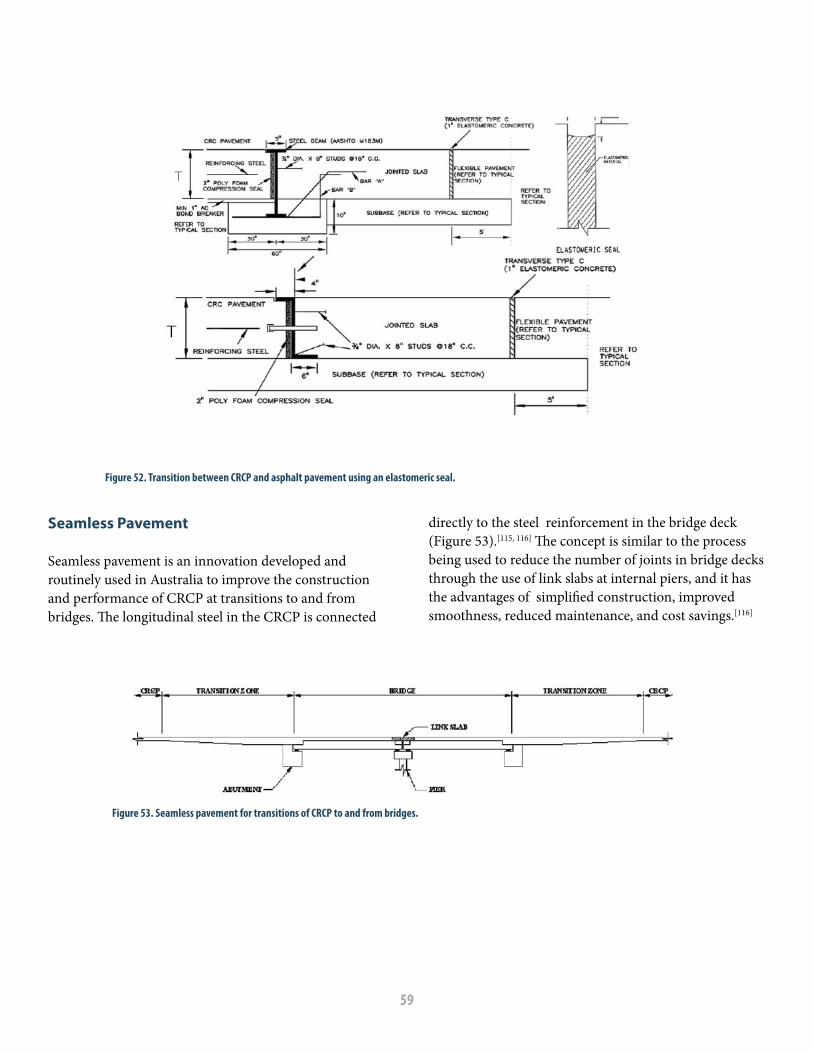
59
Seamless Pavement
Seamless pavement is an innovation developed and routinely used in Australia to improve the construction and performance of CRCP at transitions to and from bridges. The longitudinal steel in the CRCP is connected
directly to the steel reinforcement in the bridge deck (Figure 53).[115, 116] The concept is similar to the process being used to reduce the number of joints in bridge decks through the use of link slabs at internal piers, and it has the advantages of simplified construction, improved smoothness, reduced maintenance, and cost savings.[116]
Figure 52. Transition between CRCP and asphalt pavement using an elastomeric seal.
Figure 53. Seamless pavement for transitions of CRCP to and from bridges.

60
Block-outs
Block-outs are needed to allow for obstructions in the CRCP, such as drop-inlets, manholes, and foundations for luminaries. These types of obstructions in CRCP should be avoided if possible or otherwise limited to outer edges of shoulders. Typically, the perimeter of the block-out is an isolation joint where the width of
the joint is 1.5 in (40 mm). An isolation joint typically is constructed with preformed fiber-board; however, the block-out joint in CRCP should instead use a compressible material that does not absorb water. Additionally, two reinforcing bars of the same size and grade as the longitudinal reinforcing steel should be tied approximately 3.0 in (75 mm) outside each corner of the block-out, as depicted in Figure 54.
where cross-traffic must continue to flow. These gaps are referred to as leave-ins or leave-outs. If paving in the gap area precedes mainline CRCP construction, the pavement gap is referred to as a leave-in, while a leave-out is a gap left open to be paved after mainline CRCP construction.
When crossovers are needed, it is recommended to pave the crossover as a leave-in before the mainline paving. Paving these sections ahead of the mainline paving prevents reinforcement slippage since it is less likely that the short length of the paved crossover will exert excessive force on the newly cast, mainline CRCP. Crack spacing in the leave-in may be greater than what develops in the mainline because of the initial free movement of the ends. However, additional
Figure 54. CRCP block-out schematic.
CROSSOVERS
Crossovers are often used during construction to provide access to through traffic. CRCP design procedures and specifications are developed around the concept of steel and concrete continuity to provide uniform and continuous load transfer across transverse cracks and resist temperature and shrinkage movements in a monolithic slab. Thus, temporary gaps in CRCP should be avoided as much as possible. Giving proper consideration during the planning stage to the paving schedule can minimize the necessity for these gaps. However, temporary gaps are necessary in some paving situations, such as providing a haul-road crossing or an intersection

61
cracks will develop over time after it is connected to the mainline pavement. If the leave-in is located in an intersection, the two sides of the intersection can be constructed separately, or the entire intersection can be constructed at once.
Experience has shown that when leave-out gaps are paved, they are subjected to higher end movement by the mainline CRCP because of temperature changes. During the first days after placing, the leave-out concrete will not have reached its full strength, and will be more susceptible to cracking, crushing, and permanent loss of bond between concrete and steel. It is recommended that special attention be given to crossovers when planning the paving schedule in order to minimize the need for leave-outs. In fact, some agencies do not permit the use of leave-outs while others, such as South Dakota, include language in their specifications to discourage leave-out gaps. In the event that a leave-out does become necessary, the following precautions should be taken to reduce distress in the leave-out concrete:[78, 113]
• Leave-out should be at least 100 ft (30 m) in lengthwith transition joints at each end.
• Leave-outs should be paved during stable weatherconditions when the daily temperature range is
small. This condition is likely to exist when the sky is cloudy and the humidity is high.
• If it becomes necessary to pave a leave-out inhot weather, the temperature of the concrete inthe free ends should be stabilized by placing anadequate layer of insulating material on the surfaceof the pavement to minimize movement. Curingcompound should be applied to new concrete in atimely manner. Insulation material should remainon adjacent pavement until the design modulus ofrupture of the leave-out concrete is attained.
• A minimum of 50 percent additionalreinforcement should be required in the leave-out and across the construction joints at bothends of the leave-out (Figure 55). The additionalreinforcement should be evenly distributedbetween every other regular reinforcement bar.
• Both additional and regular reinforcement bars shouldextend into the leave-out no less than 7.0 ft (2.1 m)and should be embedded no less than 3.0 ft (0.9 m)into the mainline CRCP adjacent to the leave-out.Splices in the leave-out area should follow the samerequirements as those followed at a construction joint.
• Because of the closer steel spacing, extreme careshould be exercised in consolidating the concrete toprevent honeycombing or voids under reinforcement,and to provide a smooth riding surface.
Figure 55. Layout of reinforcement in leave-out section.

62
Temporary Crossovers This type of crossover is sometimes needed to accommodate truck movement across the grade after reinforcing steel is in place. These crossovers can be installed by placing wooden mats over the steel after temporary removal of bar supports. The wooden mats can be designed so that cleats underneath are spaced to fit between longitudinal and transverse reinforcing bars.
SHOULDERS, RAMPS, AND INTERSECTIONS
Concrete and asphalt shoulders, auxiliary lanes, and ramps can be constructed in conjunction with a mainline CRCP. The design and construction of these components will affect the cost of CRCP construction, maintenance requirements and can significantly impact long-term performance of the mainline CRCP. The construction of intersections also requires special consideration in the design and construction phases of the CRCP project.
Shoulders and Auxiliary Lanes
Typical shoulder and auxiliary lane design options for CRCP traffic lanes include:
• JPCP placed after the mainline traffic lanes with or without dowels, depending upon current traffic or anticipated future use. Tie bars are used to provide some level of load transfer to the CRCP. Concrete for tied concrete shoulders should be placed after the mainline CRCP has reached its design strength.
• Asphalt concrete placed adjacent to an extended outside lane of the mainline CRCP. The mainline slab should extend at least 1.0 ft to 2 ft (0.3 m to 0.6 m) into the shoulder area to reduce deflections and erosion potential at the free edge of the CRCP traffic lanes.
• CRCP with the same cross-section as the mainline lanes so it may serve as a traffic lane when needed.
Key factors to consider in the design and construction of shoulders and auxiliary lanes include the following:
• Amount of load transfer provided by the shoulder (or auxiliary lane) throughout the design life of the pavement.
• Ability to prevent the infiltration of moisture to susceptible layers under the loaded area of the pavement.
• Maintenance requirements. • Ability to use shoulder for regular traffic
(emergencies, increased capacity, and/or parking).
The most commonly encountered shoulder types with CRCP are either tied concrete or asphalt. While asphalt shoulders may have lower initial construction costs than concrete shoulders, the longitudinal joint between the CRCP and the asphalt shoulder often requires significant maintenance activities throughout the life of the pavement. On the other hand, tied concrete shoulders provide enhanced lateral structural support resulting in a reduction in both pavement deflection and stress under traffic loading, leading to improved performance (see Figure 17 and related text). Other factors that require consideration when selecting the shoulder type include the effect the shoulder will have on drainage as well as the effect that the environment may have on shoulder performance.
Concrete Shoulders Concrete shoulders should be tied to the mainline either by extending the transverse steel from the mainline CRCP into the shoulder with a longitudinal contraction joint provided at the juncture between the travel lane and the shoulder; or by placing properly spaced and sized tie bars along the longitudinal joint. While tied concrete shoulders can be paved in a second pass after the mainline CRCP has reached its design strength, additional benefits are obtained from shoulders paved monolithically with the mainline pavement since a significant improvement in load transfer is achieved by aggregate interlock at the longitudinal joint. Tie bars provide load transfer and keep the longitudinal joint tightly closed, which minimizes water infiltration into the pavement and base structure. Tie bar installation at the shoulder follows the same construction practice as previously described for longitudinal mainline construction joints. Almost all states have abandoned the practice of bending Grade 40 (Grade 300) tie bars to connect concrete shoulders because of joint separation issues. Some agencies are now using a multi-piece threaded tie bar as was shown in Figure 29. One part of

63
the bar is tied to the reinforcement in the CRCP traffic lane and after concrete is placed the other part is threaded into it.
Full-width CRCP shoulders provide a uniform pavement section that can later be utilized when additional lanes are required. Jointed concrete shoulders may provide savings in comparison to CRCP shoulders in terms of initial construction cost, although future maintenance may be significant. Where jointed concrete shoulders are tied to CRCP, the shoulder should be sawed transverse to the direction of traffic to a depth of one-third the pavement thickness at no more than 15-ft (5-m) intervals. If the shoulder will be used for mainline traffic, or for parked truck traffic, consideration should be given to the use of dowels at the transverse joints in the shoulder to prevent faulting and provide additional load transfer. As stated earlier, concrete for tied jointed-concrete shoulders should be placed after the CRCP has gained its design strength. Also, tie bars between the shoulder and mainline CRCP should be placed within the middle third of the shoulder panels to avoid interference with the functioning of the transverse contraction joints in the shoulder.
Corrugations (rumble strips) that are impressed into the inner and outer edges of the mainline CRCP while the concrete is in a plastic state have proven to be an effective means for alerting drivers that they are moving onto the shoulder. The width and depth of the corrugations are dependent on average speed allowed on the roadway. In a 50-mph to 70-mph (80-kph to 110-kph) range, a width of 4.0 ft to 6.0 ft (1.0 m to 2.0 m), and a spacing of 60 ft to 100 ft (18 m to 30 m) are appropriate.[113] Care should be taken to make certain that the impressed corrugations meet the plan details throughout the setting process and that the concrete is not weakened by late disturbance.[113]
Widened Lane The use of full-width CRCP paved shoulders is desirable for many reasons. However, the additional cost of this design may not be warranted on all projects. As an alternative, experience has shown that monolithically extending the outer CRCP lane by at least 1.0 ft (0.3 m) into the shoulder to create an extended or widened lane will significantly reduce deflection of the free edge and
the development of punchouts. The use of a widened lane can provide either additional pavement life or an opportunity to decrease the CRCP thickness. Placement of rumble strips on the shoulder portion of a widened lane also should be assessed. Some states have opted to use widened lanes with asphalt shoulders, providing a trade-off between initial construction cost and enhanced pavement performance.
Asphalt Shoulders Studies of edge punchouts in CRCP have shown that asphalt shoulders generally do not perform as well as concrete shoulders; however, if asphalt shoulders are selected, the following guidelines should be considered:
• Include anti-stripping agents in the asphalt mixtureused in the shoulder.
• Include proper sub-drainage, such as edge drainsbeneath the lane/shoulder joints or day-lightedpermeable bases, to drain water infiltrating thelane-shoulder joint and to keep the base structurefree of moisture.
• Ensure that the asphalt is compacted to adequatedensity, particularly at the lane-shoulder interface.
The use of tied concrete shoulders in lieu of flexible shoulders will minimize problems associated with the infiltration of surface water into the foundation through the longitudinal joint between the mainline pavement and the asphalt shoulder. Concrete shoulders also have the potential to facilitate construction activities, improve pavement performance and reduce maintenance costs.[117]
Ramps Selection of pavement type for ramps and acceleration/deceleration lanes should take into account similar considerations as those described for shoulders in the preceding paragraphs. Well-designed and well-constructed ramps and auxiliary lanes are essential to the satisfactory performance of CRCP. In general, CRCP with the same features as the mainline CRCP is recommended for the auxiliary lanes. Pavement ramps can be either CRCP or jointed concrete pavement; however, A CRCP ramp will require a transition feature where it meets the mainline CRCP.[113]

64
Extra care should be taken to fully consolidate concrete in the ramp, especially around construction joints, and to achieve a satisfactory riding surface. The performance of the longitudinal joint between the ramp and mainline CRCP will depend on the differential movement between these two elements. If the ramp is constructed with jointed concrete pavement, it is recommended to
provide a short joint spacing similar to jointed concrete shoulders to minimize movement and potential cracking of the CRCP. Recommended layouts for ramp connections and jointing details are provided in Figure 56 and Figure 57. More information about mainline CRCP connections to different ramp types and their respective details are available.[111]
Figure 56. Recommended layouts for ramp connections.
Figure 57. Jointing details for ramp connections.

65
Intersections Intersections where two CRCP alignments intersect present a unique challenge in terms of maintaining continuity of reinforcement in both directions through the intersection. A recent research report from TxDOT documents best practices for design and construction of CRCP in transition areas, including intersections.[111]
Figure 58 shows design details used by TxDOT for maintaining the continuity of reinforcement in both
directions through an intersection of two CRCP alignments. The longitudinal reinforcement for the pavement in one direction provides the transverse reinforcement for the pavement in the other direction and vice versa. The TxDOT report also provides design details for the intersection of two CRCP alignments where maintaining the continuity of reinforcement in only one direction is necessary, as well as design details for the intersection of a CRCP with other types of pavement.
Figure 58. Design details for intersection of two CRCP alignments (Texas).
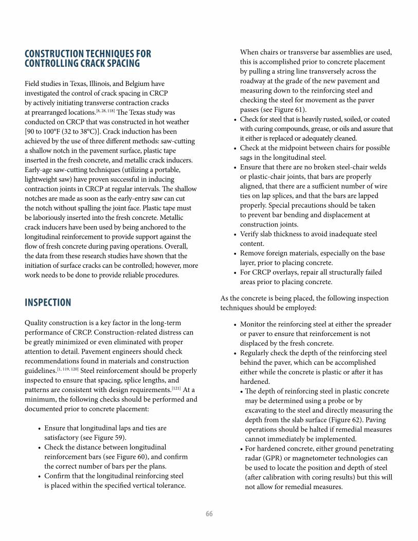
66
CONSTRUCTION TECHNIQUES FOR CONTROLLING CRACK SPACING
Field studies in Texas, Illinois, and Belgium have investigated the control of crack spacing in CRCP by actively initiating transverse contraction cracks at prearranged locations.[8, 28, 118] The Texas study was conducted on CRCP that was constructed in hot weather [90 to 100°F (32 to 38°C)]. Crack induction has been achieved by the use of three different methods: saw-cutting a shallow notch in the pavement surface, plastic tape inserted in the fresh concrete, and metallic crack inducers. Early-age saw-cutting techniques (utilizing a portable, lightweight saw) have proven successful in inducing contraction joints in CRCP at regular intervals. The shallow notches are made as soon as the early-entry saw can cut the notch without spalling the joint face. Plastic tape must be laboriously inserted into the fresh concrete. Metallic crack inducers have been used by being anchored to the longitudinal reinforcement to provide support against the flow of fresh concrete during paving operations. Overall, the data from these research studies have shown that the initiation of surface cracks can be controlled; however, more work needs to be done to provide reliable procedures.
INSPECTION
Quality construction is a key factor in the long-term performance of CRCP. Construction-related distress can be greatly minimized or even eliminated with proper attention to detail. Pavement engineers should check recommendations found in materials and construction guidelines.[1, 119, 120] Steel reinforcement should be properly inspected to ensure that spacing, splice lengths, and patterns are consistent with design requirements.[121] At a minimum, the following checks should be performed and documented prior to concrete placement:
• Ensure that longitudinal laps and ties aresatisfactory (see Figure 59).
• Check the distance between longitudinalreinforcement bars (see Figure 60), and confirmthe correct number of bars per the plans.
• Confirm that the longitudinal reinforcing steelis placed within the specified vertical tolerance.
When chairs or transverse bar assemblies are used, this is accomplished prior to concrete placement by pulling a string line transversely across the roadway at the grade of the new pavement and measuring down to the reinforcing steel and checking the steel for movement as the paver passes (see Figure 61).
• Check for steel that is heavily rusted, soiled, or coatedwith curing compounds, grease, or oils and assure that it either is replaced or adequately cleaned.
• Check at the midpoint between chairs for possiblesags in the longitudinal steel.
• Ensure that there are no broken steel-chair weldsor plastic-chair joints, that bars are properly aligned, that there are a sufficient number of wire ties on lap splices, and that the bars are lapped properly. Special precautions should be taken to prevent bar bending and displacement at construction joints.
• Verify slab thickness to avoid inadequate steelcontent.
• Remove foreign materials, especially on the baselayer, prior to placing concrete.
• For CRCP overlays, repair all structurally failedareas prior to placing concrete.
As the concrete is being placed, the following inspection techniques should be employed:
• Monitor the reinforcing steel at either the spreaderor paver to ensure that reinforcement is notdisplaced by the fresh concrete.
• Regularly check the depth of the reinforcing steelbehind the paver, which can be accomplishedeither while the concrete is plastic or after it hashardened.• The depth of reinforcing steel in plastic concrete
may be determined using a probe or byexcavating to the steel and directly measuring thedepth from the slab surface (Figure 62). Pavingoperations should be halted if remedial measurescannot immediately be implemented.
• For hardened concrete, either ground penetratingradar (GPR) or magnetometer technologies canbe used to locate the position and depth of steel(after calibration with coring results) but this willnot allow for remedial measures.

67
Troubleshooting and Precautions
• When placing CRCP on asphalt bases, both chairsand transverse bar assemblies need base plates toprevent them from sinking into the base duringwarm weather.
• The steel mat does not need to be pinned to thebase; and, the restraint from pinning may adverselyaffect long-term CRCP performance.
• Longitudinal reinforcement should be spaced toavoid longitudinal saw cut joints directly above areinforcing bar.
• Epoxy-coated rebar should only be tied with coatedtie wires and any damage to the epoxy coating shouldbe repaired according to written instructions from themanufacturer prior to placement of concrete.
• Mechanical insertion of tie bars should beallowed as long as edge slumping is not aproblem.
• Tack welding of reinforcing bars in the fieldshould not be allowed.
• Manholes and drop-inlets should be isolatedfrom the CRCP, and a reinforcing bar shouldbe placed around the perimeter of theobstruction.
• Any increase in pavement thickness should beaccompanied by an increase in reinforcement tomaintain the desired steel percentage.
• CRCP should not be tied to noise walls, retainingwalls, or other structures.
• Paving should not be allowed until thereinforcement has passed field inspection.
Figure 59. Longitudinal reinforcement lap splices and ties.
Figure 60. Lateral spacing of longitudinal steel.
Figure 61. Checking for position and movement of longitudinal steel.
Figure 62. Probing fresh concrete to check the depth of longitudinal steel.

68

69
CHAPTER 6 CRCP PERFORMANCE

70
CRCP has been constructed all over the world with different concrete materials and support layers, under varying environmental conditions, and subjected to different load levels and repetitions. In all cases it has shown that it can have satisfactory long-term performance if designed and constructed properly. The following paragraphs briefly summarize CRCP performance both in the U.S. and in other countries having experiences with CRCP.
CRCP EXPERIENCE IN THE U.S.
CRCP was not widely used in the U.S. until the 1960s and 1970s, during the construction of the Interstate Highway System. The first experimental use of CRCP was in Virginia in 1921, followed by additional experimental sections in Indiana in 1938 and in Illinois and New Jersey in 1947. Since that time the use of CRCP has been implemented in a number of states including California, Georgia, Illinois, Indiana, Louisiana, North Dakota, Oklahoma, Oregon, South Dakota, Texas and Virginia. A summary of CRCP experiences in the U.S. is described in the following paragraphs.
CaliforniaCalifornia constructed an experimental 1.0-mile (1.6-km) long two-lane CRCP section in 1949 on US-40 near Fairfield. Currently, this CRCP serves as the two westbound, inside lanes of I-80. Parts of the section received diamond grinding in the 1990s and were overlaid with asphalt in 2010. This CRCP section was 8.0 in (200 mm) thick and featured two longitudinal steel contents: 0.5 percent with a higher-strength steel and 0.63 percent with a lower-strength steel.[122]
A second experimental CRCP section was constructed in 1971, with LTPP surveys indicating minimal distresses for 30 years. An asphalt overlay was placed on this section in the 2000s. In the mid-2000s, Caltrans adopted CRCP structural designs, specifications, and standard drawings for its highway design manual. Presently, Caltrans is using CRCP for new pavements, for truck-lane replacements, as an overlay for pavement sections with heavy truck traffic, and in locations where long-term performance with minimal maintenance is necessary.
Modern CRCP in California is constructed with a thickness of 10 to 12 in (254 to 305 mm) and 0.70 percent longitudinal steel placed 4.0 in (102 mm) below the pavement surface. A 4.0-in (102-mm) non-erodible base (ATB or CTB) is used on a 6-in (152-mm) granular subbase. The subgrade is treated when needed.
GeorgiaGeorgia first used CRCP in 1969. Based on successful performance with minimal maintenance, CRCP designs were used often in the early 2000s during reconstruction of interstate highways in Georgia. Various pavement options are considered for a given project location based on life cycle cost, with CRCP most often being viable for locations with heavy truck traffic or high traffic volumes. Typical design details for CRCP include a 12-in (305-mm) slab placed directly on base material, or an 11-in (280-mm) CRCP used as an overlay of an existing pavement. A longitudinal steel content of 0.70 percent is specified, and the steel is placed 3.5 in (89 mm) to 4.25 in (108 mm) below the slab surface. The base layer for CRCP is a 3-in (76-mm) ATB over a 12-in (305-mm) aggregate base.[17] Georgia has constructed a number of CRCP overlays, the first being constructed over a jointed concrete pavement in 1971.[123]
IllinoisIllinois has been constructing CRCP for several decades, having first experimented with CRCP test sections constructed in 1947, in Vandalia (Figure 63). Only Texas has more CRCP sections than Illinois. CRCP typically is selected for pavement designs with greater than 35 to 60 million ESALS. CRCP has been used by Illinois DOT on a number of freeways around Chicago including I-90, I-94, I-55, and I-290,[124] and on I-80. The Illinois State Toll Highway Authority has used CRCP on several projects including the reconstruction of part of I-294. Interstate highways in Illinois have more than 2,650 miles (4,270 km) of two-lane CRCP. The majority of the CRCP in Illinois ranges in thickness from 7.0 in (178 mm) to 10 in (254 mm) and contains 0.60 to 0.65 percent steel.[40] One study revealed that the CRCP sections in Illinois have carried more ESALs than estimated in the original designs, and have lasted anywhere from two to six times longer than initially projected.[40] Another study indicated that an 8.0-in CRCP in Illinois has a projected longevity

71
and traffic capacity equal to that of a 10-in (254-mm) jointed concrete pavement.[125]
The Illinois DOT generally uses tied jointed-concrete shoulders for CRCP. Additionally, Illinois has successfully used jointed concrete containing recycled aggregate to replace asphalt shoulders that originally were used with some CRCP sections. Illinois also has experimented with CRCP containing recycled aggregates. A 10-in (254-mm) CRCP section with recycled aggregate in the concrete was constructed during 1986-1987 on I-57. This CRCP provided 23 years of satisfactory service and subsequently was overlaid with asphalt.[126]
Illinois DOT has frequently used asphalt with success to overlay CRCP, with good performance reported in terms of punchouts and cracks reflecting through to the asphalt surface. For CRCP sections entering the end of their service life, the Illinois DOT has successfully constructed CRCP overlays, with thicknesses ranging from 8 to 12 in (203 to 305 mm). More information on the use of CRCP as an overlay is available in Chapter 8 of this manual.
In 2002, the Illinois DOT began an Extended Life Pavement Program utilizing CRCP with design lives of 30 to 40 years. The design features for this CRCP included thicknesses up to 14 in (350 mm), longitudinal steel content within a range from 0.70 to 0.80 percent, and an increased depth of steel placement ranging from 3.5 to 4.5 in (90 to 115 mm). The design features also included a 4.0- to 6.0-in (102- to 152-mm) ATB on top of a 12-in (305-mm) aggregate subbase and a lime-treated subgrade. Extended-life CRCP sections have been placed on I-80, I-90/94, I-70, I-290, and I-74.[127]
IndianaIndiana was one of the first states to experiment with CRCP, having conducted studies in 1938 on US-40 using different section lengths ranging from 20 ft to 1,310 ft (6 m to 400 m) with longitudinal steel contents ranging from 0.7 to 1.82 percent.[129, 130] These experimental CRCP sections comprised the second major field study by the Public Roads Administration (now FHWA) following the construction of CRCP in 1921, on Columbia Pike in Virginia. Indiana had constructed 695.5 miles (1159 km) of two-lane CRCP by 1971;[131] however, Indiana
discontinued the use of CRCP for a number of years. Recently Indiana has begun using CRCP again, such as on the I-65/I-70 split south of Indianapolis in 2014.
LouisianaThe Louisiana Department of Transportation and Development (DOTD) experimented with CRCP design during construction of the interstate system in the 1960s and 1970s, utilizing an 8-in (203 mm) thickness for sections on I-10, I-12, I-20, US-90, and LA 3132. Some CRCP sections, on I-20 in the Mississippi Delta and on I-10 between New Orleans and Baton Rouge, performed very well with years of service and traffic counts exceeding original design assumptions. Some sections along I-10 were overlaid in 2009. However, other sections with soft subgrade conditions experienced differential settlement and cracking while other sections experienced premature punchouts due to poor base or subgrade conditions, poor construction techniques, insufficient slab thickness, and/or rounded aggregates.[132] These premature failures resulted in a moratorium on the use of CRCP in 1975. In 1996, the Louisiana DOTD conducted a study to evaluate the most cost-effective design for reconstruction of a section of US-190. For a 30-year design life, CRCP was selected as the best option and construction was completed in 2003. Shortly thereafter, a 14-in (356-mm) thick CRCP also was selected for use on weigh-station ramps on I-20. CRCP also was used on a short segment of mainline I-10.[132]
Figure 63. Construction of the 1947 Vandalia CRCP test sections (Illinois).

72
North DakotaNorth Dakota has 570 miles (950 km) of centerline pavement on I-29 and I-94, about 26 percent of which was constructed with CRCP in the 1960s and 1970s.[133] Some of the interstate CRCP has been overlaid with asphalt. CRCP is being considered more often because of its lower maintenance cost. Also, expansive soils found in North Dakota require a permeable base for jointed concrete pavement designs; however, permeable bases are not used for CRCP since the steel in the pavement is relied upon to control the cracking and to retain the integrity of the structure.
OklahomaThe first CRCP section built in Oklahoma was in 1969. Presently, the Oklahoma DOT constructs a number of CRCP projects annually, having used it on all interstate highway routes in the state and on several US routes. The selection of the pavement type in Oklahoma is dependent on the projected traffic levels and the soil conditions. The modern CRCP design for reconstruction and unbonded overlays in Oklahoma uses a thickness of 8 to 12 in (203 to 305 mm) with 0.70 percent longitudinal steel placed at mid-depth.[17] Tied jointed concrete shoulders are used in Oklahoma for CRCP. Widening of I-35 through Oklahoma City utilized a 10-in (254-mm) thick CRCP with 0.70 percent longitudinal steel on top of a 4-in (102-mm) open-graded base and a 12-in (305 mm) aggregate base.[135] As of 2010, none of the original CRCP sections had been reconstructed and 25 percent had required rehabilitation. This level of performance compares very favorably to the performance of the entire pavement inventory where six percent required reconstruction and 84 percent required rehabilitation.[17]
OregonThe 560 miles (901 km) of CRCP in Oregon has an average age of 23 years. Oregon constructed its first CRCP section in 1963, which had a thickness of 8.0 in (203 mm) with 0.60 percent longitudinal steel. That CRCP performed well and received an asphalt overlay in 2004. CRCP design thicknesses of 8 to 11 in (203 to 279 mm) with 0.70 percent steel have been used since the late 1970s. Additionally, 14-ft (4.3-m) widened slabs are used for the outside lane with an asphalt shoulder. As of 2010, it was reported that 59 percent of CRCP in Oregon
had not received any overlay; 22 percent had received a 2.0-in (51-mm) asphalt overlay; 16 percent had received a 4.0-in (102-mm) asphalt overlay; and 3 percent had been either reconstructed or rubblized.[17] The Oregon DOT uses CRCP on rehabilitation and reconstruction projects where heavy truck traffic is projected. An example is the CRCP inlay on some sections of the truck lane on I-84.
South DakotaThe oldest CRCP in South Dakota is a 1.0-mile (1.6 km) segment built in 1963 near Sioux Falls. It has performed well, but was replaced in 2004 because the JRCP leading up to and away from it was in poor condition. Since 1995, the South Dakota DOT has been systematically replacing segments of deteriorated interstate pavements, both asphalt and jointed concrete, with CRCP. As of 2001, approximately 33 percent of South Dakota’s 241 miles (402 km) of centerline interstate pavement were CRCP.[133] A 2012 report stated that CRCP comprised 40 percent of South Dakota’s interstate CRCP.[17]
Newer CRCP sections range in thickness from 8 in to 12 in (203 mm to 305 mm) with 0.66 to 0.69 percent longitudinal steel. The CRCP is placed on a 5-in (127 mm) granular base, which can be rubblized concrete from the original pavement, when available.[17] Like North Dakota, South Dakota relies on the steel in the CRCP to control cracking when placed over expansive soils.[133]
Some of the newer CRCP experienced Y-cracking, cluster cracking and early-age spalling. A study of these issues concluded that the design specifications needed to be modified by limiting the aggregate size to 100 percent passing the 1.5-in (38-mm) sieve with 10 percent retained on the 1.0-in (25-mm) sieve, limiting the steel content to a maximum of 0.6 percent, and by applying curing compound within 30 minutes of finishing the surface.[134]
TexasTexas has the largest inventory of CRCP in the U.S., with nearly 13,600 miles (21,900 km) of traffic lanes in service in 2014. The first use of CRCP in Texas was in 1951 in Fort Worth, and since then TxDOT has continued to improve the performance of CRCP through research, having evaluated the effects of the environment during construction, percent steel, steel bond area, coarse

73
aggregate type, the relationship between concrete strength and crack spacing, crack width, and other factors.[136] The nationally recognized failure mechanism for CRCP is punchouts, and by 2010 the CRCP in Texas had demonstrated an extremely low average rate of one punchout per 8.8 miles (14.2 km) of traffic lanes.[17] Rigid pavements in Texas are designed for a performance period of 30 years. CRCP thickness, based on projected traffic and other design variables, is allowed to be in the range of 6.0 to 13.0 inches (152 to 330 mm) in 0.5-inch (13-mm) increments.
TxDOT has been active in evaluating the performance of CRCP constructed with concrete containing non-traditional materials, such as recycled concrete aggregates, which have demonstrated satisfactory performance.[137] Additionally, CRCP with lightweight aggregates has been shown to be a viable option;[138] and, fiber-reinforced CRCP has been shown to reduce the spalling of transverse cracks.[26] TxDOT also has used CRCP to overlay existing pavements (see Chapter 8).
VirginiaVirginia had the very first CRCP constructed in the U.S. in 1921 on Columbia Pike in Arlington. The 1.75-mile (2.8-km) experimental section was a Public Roads Administration (now FHWA) project to evaluate the effects of slab thickness, steel content, and cross-section design.[130] The first modern CRCP in Virginia was constructed in 1966 on a 15-mile (24-km) section of I-64 through Richmond. The Virginia DOT (VDOT) currently has around 561 miles (903 km) of CRCP lane-miles, about 75 percent of which is on interstate highways.[139]
CRCP construction in Virginia from the 1960s to the 1980s used a slab thickness of 8.0 in (203 mm) with 0.60 percent longitudinal steel placed 3.5 in (89 mm) below the concrete surface.[140] The CRCP was placed on a 4- to 6-in (102- to 152-mm) thickness of CTB. During this timeframe, asphalt shoulders were commonly used. At the end of its service life, CRCP in Virginia is overlaid with asphalt.
Starting in about 2001, VDOT made significant changes to its CRCP design and construction requirements in recognition of the fact that earlier CRCP did not perform
as expected – especially the CRCP on I-295, the eastern beltway around Richmond, where tube-feeding of longitudinal steel resulted in random and unacceptable fluctuations in the depth of the steel. The steel percentage was raised to 0.7 and CRCP is placed on a 3-in (75-mm) ATB drainage layer. All steel must be placed on chairs with transverse bars for support, tube-feeding of steel is not allowed, and there are minimum required settings for vibration of concrete during paving. In addition to these changes, the thickness of the CRCP is required to be in the range of 11.0 in to 13.0 in (280 mm to 330 mm), based on anticipated traffic and other design variables. Some projects have tied concrete shoulders, but that is not required. One project used randomly-spaced transverse tines to reduce tire noise, and was found to be a satisfactory option; however, that feature has not been adopted in VDOT specifications. The performance of all projects constructed since these changes were implemented has been excellent with virtually no maintenance required. There have been some isolated instances where spalls at transverse cracks and at headers have required minor repairs, which have been handled by State forces. The smoothness of CRCP constructed in Virginia in 2001 and later has remained satisfactory since the time of construction.
INTERNATIONAL CRCP EXPERIENCE
The use of CRCP is documented in Australia, Belgium, Canada, China, France, Germany, the Netherlands, South Africa, Spain, and the United Kingdom. A brief summary of experience with CRCP in those countries is provided in the following paragraphs.
AustraliaAustralia first started using CRCP pavements in 1975 on a 5.5-km (3.4-mile) section of the Pacific Highway at Clybucca Flat, New South Wales. This 40-year design life CRCP had a thickness of 230 mm (9.1 in) with 0.6 percent steel on a 130-mm (5.1-in) thickness of lean concrete having a compressive strength 8 MPa (1,160 psi).[150]
Australia also has developed an innovative “seamless pavement” utilizing CRCP that eliminates transition

74
details at bridges by connecting the longitudinal reinforcement in the CRCP to the reinforcement in the bridge deck. This method of CRCP construction was first used on the M7 Motorway near Sydney in 2005.[116] The method has since been used at more than 50 locations in Australia. The method has improved ride at the bridge approach and has caused no distress. It continues to be used not only because it simplifies construction but also because it reduces maintenance and road noise.[151]
BelgiumCRCP is a popular choice for rigid pavements in Belgium, having first been constructed there in 1950. In the 1970s, over 18 million m2 (194 million ft2) of CRCP were placed in Belgium.[141] A longitudinal steel content of 0.85 percent was generally used between 1970 and 1977 in a 20-cm (7.9-in) thickness of CRCP. The steel content was reduced to 0.67 percent between 1977 and 1991 and punchouts became a problem. The steel content was increased to 0.72 percent from 1992 to 1995. The modern design for CRCP in Belgium since 1995 uses 0.76 percent steel in a 23-cm (9.1-in) thickness of CRCP placed on a 6-cm (2.4-in) ATB and a 20-cm (7.9-in) LCB.[141] The longitudinal reinforcement typically is placed 8 cm (3.1 in) below the surface of the concrete.
A significant CRCP project in Belgium was the reconstruction in 2001 of the Antwerp Ring Road, which is a 14.2-km (8.8-mile) road with four to seven lanes in each direction. With six connecting freeways, the busiest section on the Ring Road carries almost 200,000 vehicles per day, 25 percent of which are trucks. The design features for the project utilized a 23-cm (9.1-in) thickness of CRCP placed on a multi-layered support system, as follows: a 5-cm (2.0-in) asphalt interlayer, a 25-cm (9.8-in) CTB, and a 15-cm (5.9-in) lean concrete subbase.[142]
Roundabout intersections also have been constructed in Belgium using CRCP. More than 50 CRCP roundabouts have been built since 1995 using either slip-form or side-form paving.[143]
Belgium experimented in 1996 with two-lift CRCP (Figure 64).[145] The CRCP had a total thickness of 22 cm (8.7 in) with an 18-cm (7.1-in) bottom lift and a 4-cm (1.6-in) top lift. This CRCP had an exposed aggregate
surface and was reported to be performing well after 17 years of service.[28] In 2007, on the E34 roadway near Antwerp, a 23-cm (9.1-in) CRCP was constructed with an 18-cm (7.1-in) bottom lift containing recycled concrete aggregates and a 5-cm (2.0-in) top lift having an exposed aggregate surface.[144] The longitudinal steel was positioned in the top portion of the bottom lift so that it was 80 mm (3.1 in) below the finished roadway surface.
Active crack control also has been the subject of field testing in Belgium. Transverse saw-cuts were made in the finished surface of a CRCP within 36 hours of concrete placement. These saw-cuts were spaced at 1.2 m (3.9 ft) with depths of either 3 cm (1.2 in) or 6 cm (2.4 in). Better transverse crack initiation was achieved with the deeper saw-cuts.[28]
CanadaThe first CRCP sections in Canada were constructed in 1958 on the Trans-Canada Highway near Calgary. These sections were designed to evaluate different pavement thicknesses and steel contents. Blowups occurred in 1968 on CRCP sections having a thickness of only 152 mm (6.0 in) with 0.72 percent longitudinal steel,[5] effectively halting the use of CRCP in Canada until recently. In 2000, a 2-km (1.2-mi) CRCP test section was constructed on Highway 13 North in Laval with a thickness of 270 mm (10.6 in) and 0.7 percent longitudinal steel; and, another CRCP project was constructed in Montréal on
Figure 64. Construction of two-lift CRCP using two slip-form pavers on the A13 roadway (Belgium).

75
Highway 40 East with a thickness of 275 mm (10.8 in) and 0.76 percent longitudinal steel. Aside from some crack spacing issues, the CRCP sections were reported to be performing satisfactorily as of 2004.[152]
Canada has also experimented with nontraditional reinforcement materials. One study in 2006 in Montréal evaluated the use of glass fiber-reinforced polymer (GFRP) (Figure 65). The experiment considered 15 different configurations with GFRP to evaluate the effect of different longitudinal GFRP contents, bar size and spacing, and layout configuration.[31]
ChinaThe use of CRCP in China has taken place between 2001 and 2005. During that time China doubled its expressway network by adding 24,700 km (15,350 mi) of pavement, parts of which were CRCP. A significant example is the 43-km (26.7-mi) section of the Zhang-Shi Freeway from Zhangjiakou to Shijiazhuang, where CRCP was constructed and overlaid with an asphalt wearing course.
FranceThe first use of CRCP in France was on the A6 roadway near Paris. The country has over 550 km (342 mi) of
CRCP traffic lanes, and over 100 km (62 mi) of traffic lanes where CRCP has been used to overlay existing pavements.[5] The thickness of CRCP varies depending on truck traffic and subgrade conditions. Typically the CRCP is placed on a 150 mm (6.0-in) LCB or a 50 mm (2.0-in) ATB and either a granular subbase or a cement-stabilized soil. The typical longitudinal steel content in France is 0.67 percent. Satisfactory performance also has been achieved with a composite pavement in which CRCP is placed on an ATB and overlaid with a thin asphalt wearing course.
GermanyGermany has just a few CRCP test sections, but on the 1.5 km (0.9 mile) stretch of experimental CRCP test sections on the A-5 Autobahn near Darmstadt, the slab thickness is 240 mm (9.5 in), which is about 25 mm (1.0 in) less than the German practice for the design of pavements would dictate for jointed concrete pavement under similar conditions. This thickness reduction was based on analyses conducted by the Technical University at Munich.[143]
The NetherlandsThe use of CRCP in The Netherlands has utilized the design features from specifications in Belgium. CRCP sections were constructed on several roadways including the A76 in 1991, the A73 in 1993, the A12 in 1998, the A5 and A50 in 2004 and 2005, and the A73 and A74 in 2006.[143] Modern design features for CRCP in The Netherlands on roadways carrying major truck traffic includes a thickness of 25 cm (9.8 in) with 0.7 percent longitudinal steel. The CRCP is placed on a 60-mm (2.4-in) asphalt base and a recycled aggregate subbase.[65] CRCP roundabouts also have been constructed in The Netherlands.[146]
South AfricaThe use of CRCP in South Africa as an overlay on the Ben Shoeman freeway, parts of which experience annual daily truck values as high as 150,000, has shown suitable performance even after 20 years.[172]
SpainThe first CRCP in Spain was constructed in 1975. Suitable performance has been reported with minimal maintenance. The typical design includes a thickness of 216 mm (8.5 in)
Figure 65. GFRP longitudinal reinforcement for CRCP (Canada).

76
on a 160-mm (6.3-in) base and a 220-mm (8.7-in) granular subbase.[5] The typical longitudinal steel content is 0.85 percent, although 0.73 percent steel also has been used.
United KingdomThe first use of modern CRCP designs in the UK was on the M62 roadway in 1975, based on designs from the U.S. and Belgium. A series of trial sections were constructed during the period 1975 to 1983 utilizing thicknesses of 210 to 250 mm (8.3 to 9.8 in) and longitudinal steel contents of 0.58 to 0.67 percent.[147] Newer CRCP designs in the UK are based on the flexural strength of the concrete and the foundation type.[148] CRCP is specified to be considered in the UK design standards, “Design Manual for Roads and Bridges”, when the predicted traffic exceeds 30 million standard axles. The minimum CRCP thickness is 200 mm (7.9 in) with 0.6 percent longitudinal steel.
Continuously reinforced concrete road-bases (CRCR) have been constructed in the UK since the 1930s, the earliest sections of which contained continuous reinforcement but often no continuous construction.[147] CRCR was used in urban areas in the 1940s and 1950s.
The M6 toll road around Birmingham was designed for 187 million standard axles for a 40-year design life. The final pavement design consisted of a thickness of 220 mm (8.7 in) with 0.6 percent longitudinal steel. The CRCP was placed on a bituminous de-bonding layer on a 230-mm (9.1 in) cement-stabilized subbase.[149] A 35-mm (1.4 in) asphalt wearing course was placed on the CRCP.
LTPP PROGRAM DATA
The LTPP program managed by FHWA collects performance data on over 2,500 pavement sections throughout the U.S. in two classes: the General Pavement Study (GPS) and the Specific Pavement Studies (SPS). CRCP data is included in 85 pavement sections found in GPS-5. Analysis of the 1999 GPS-5 data found that the CRCP sections retained smoothness (IRI) over time with minimal maintenance. Among these 85 pavement sections, 13 were identified as having performed exceptionally well with 20 or more years of service without high-severity cracking, punchouts, or patches and with an average IRI of less than 95 in/mi (1.5 m/km). All sections exhibited high compressive strength and high elastic modulus, were placed on a treated base, had a small crack spacing with a LTE greater than 90 percent, and a longitudinal steel content greater than 0.59 percent.[100]
As of 2015, 42 of the 85 CRCP sections remained active in the GPS-5 database. These active sections are in Alabama, Arkansas, California, Delaware, Illinois, Indiana, Mississippi, Ohio, Oklahoma, Oregon, South Carolina, Texas, and Virginia. The average age of all sections is 36 years. The oldest sections are 49 years old and are located in Illinois. The youngest CRCP section in the GPS-5 database is located in Oklahoma and is 25 years old. The top three states represented in the active GPS-5 database are Texas with 15 sections, Oregon with 6 sections and Illinois with 4 sections.

77
CHAPTER 7 CRCP RESTORATION AND RESURFACING

78
The purpose of this chapter is to provide information on best practices for extending the service life of CRCP. The procedures described consist of defining the problem, identifying potential solutions, and selecting the preferred rehabilitation alternatives. The rehabilitation strategies described comprise two categories: restoration and resurfacing.
Restoration activities preserve the existing pavement by repairing isolated or localized areas of distress in the CRCP and prevent their reoccurrence by stopping or delaying the deterioration process. Restoration activities include preventive maintenance and repair methods and can be utilized either without or in conjunction with pavement resurfacing methods.
Resurfacing activities, or overlays, significantly increase the structural or functional capacity of an existing pavement. These treatments are not localized, but are applied over the entire surface of the existing pavement. Overlays are used when restoration techniques are no longer sufficient or cost effective, but before reconstruction is required.
When restoration and resurfacing treatments are applied correctly and in a timely manner, the service life of an existing CRCP can be extended by 10 to 25 years or more while maintaining the structural integrity of the existing CRCP. Figure 66 is a flowchart indicating the process for assessing the need for restoration or resurfacing activities for CRCP. The process begins with identification of distresses and evaluation of the options. Once the need for either restoration or resurfacing is identified, a more thorough condition assessment should be performed utilizing techniques including visual surveys and non-destructive testing.
Figure 66. Decision tree for assessing the need for restoration or resurfacing.

79
CONDITION ASSESSMENT
In order to develop the best rehabilitation strategy, the condition of the existing pavement must be thoroughly evaluated using visual condition surveys, deflection testing, and profile measurements. The data that should be collected can be divided into the following categories:
• Pavement condition: structural and functional• Pavement materials and foundation properties:
surface, subbase, and subgrade• Existing pavement layers and thicknesses• Drainage conditions• Climatic conditions• Traffic volumes and loading• Geometric and safety factors
The condition survey provides information on the pavement structural condition via a visual distress evaluation. This survey also documents any previous maintenance activities performed, and the condition of the shoulders. A functional condition can be assessed through pavement profile measurements to quantify the pavement smoothness, skid testing for side and kinetic friction numbers, and if possible noise measurements. A drainage survey (including local climatic conditions) should also be conducted at this time, along with the collection of field samples. Subsequent laboratory testing provides information on the properties of the pavement materials and soils. Special considerations to keep in mind when performing the condition survey include the traffic volumes and loads, current pavement structure, and geometric and safety factors. For more significant understanding of the underlying pavement structural capacity, deflection tests can be used to measure LTE at cracks and joints, check the uniformity of deflection over the section, and to detect voids under the CRCP. The results are also used to back-calculate the thickness and stiffness of the layers comprising the pavement structure. After all of the data are collected, the data should be analyzed to identify the mechanisms causing the observed deterioration. With this information, the proper repair or rehabilitation strategy can be selected.
Pavement condition data can be used to assess the variability of pavement performance—assessing the
rate of deterioration as it varies from point to point along the highway. A variability assessment can be used to determine whether the entire pavement should be resurfaced or whether only localized areas of restoration are needed. Periodic pavement evaluations are especially beneficial because they reveal the rate of deterioration of the pavement. They also assist in identifying deficiencies before they evolve into more significant structural distresses. Preventive, preservative, or corrective actions can be applied at the most opportune time if periodic surveys are conducted. Quite often, each agency has standard data collection and evaluation procedures that best suit its personnel and equipment resources.
Visual Condition SurveyBefore any rehabilitation project is initiated, a visual condition survey of the pavement should be conducted. The distresses visible on the surface of the pavement provide insight into the current structural and functional condition of the pavement. A visual condition survey is often described in terms of a distress survey, a drainage survey, field sampling and testing, and special considerations.
Results from a visual condition survey may be presented graphically in the form of strip charts or historical performance charts that detail the condition of the pavement at various points along the project length. When used in conjunction with other field tests listed in this chapter, the pavement performance is more accurately characterized. Methods used to conduct visual condition surveys include windshield surveys, walking the pavement, and automated survey equipment. It may be useful to drive the pavement prior to the visual survey to obtain a sense of the distresses that are likely to exist based on the ride quality and quick visual assessment.
DISTRESS SURVEY A distress is defined as any visible defect or form of deterioration on the surface of a pavement. For CRCP, distresses include punchouts, wide transverse cracks, longitudinal cracks, crack spalling, and construction and transition joint deterioration. Other distresses that are more common to JPCP may also occur in CRCP, such as faulting, pumping, blowups, and patch deterioration. Materials-related distresses can occur in both pavement

80
types and can include D-cracking, ASR, freeze-thaw damage, pop-outs, scaling, corrosion, swelling, and depressions. The mechanisms behind each distress can be described in terms of traffic loads, climatic conditions, materials incompatibilities, or a combination of all three. The purpose of a distress survey is twofold: (1) to document the condition of the pavement and (2) to characterize the distresses by type, severity, and amount (relative area).
The Distress Identification Manual for the Long-TermPavement Performance Program is one of the most widely cited distress identification manuals.[154] It has standardized definitions of the different distress types, allowing for uniformity in identifying their severity and extent. If the type, severity, and extent of the distress are not accurately noted in the survey, it may prove difficult to optimize the rehabilitation strategy. It is important that the survey team review all current and historical pavement records prior to performing a distress survey so they know what to look for while conducting the survey.
DRAINAGE SURVEY Distresses in rigid pavements like CRCP can be caused or accelerated by the presence of excess moisture in the pavement structure. A drainage assessment will reveal if drainage improvements are needed or if the current system is not functioning as designed. Recognizing this, drainage surveys are performed to identify signs of moisture or moisture-related distresses in the pavement and to document the pavement drainage conditions (topography, cross slopes ditches, and drainage inlets and outlets if present).
Field Sampling and Testing To properly characterize the existing pavement, the distress and drainage surveys should be supplemented with the results from laboratory tests on samples of the pavement structure. Destructive testing of core samples taken from the concrete, base, subbase, and subgrade allow for a more in-depth and accurate analysis of the in-place materials and their engineering properties than the visual surveys provide. In addition, cores can confirm the layer thicknesses in the pavement structure, and can be used to identify materials-related distresses.
Cores are commonly taken at locations observed to have structural deficiencies. They are also taken to validate or complement non-destructive test results. Other guidelines for field sampling and testing include the following:[155]
• For punchouts, wide cracks, and any otherstructural distresses, cores should be taken at thedistress to determine the pavement thickness andconcrete strength.
• For deteriorated longitudinal and constructionjoints, cores should be taken through the jointsto determine whether or not they are workingand whether the base layer is eroding. If tie barcorrosion is suspected, the core should be takenthrough the bar to determine the extent of thecorrosion and loss of bond.
• For materials-related distresses, like D-crackingand reactive aggregates, petrographic examinationand testing of field samples is recommended.
• For drainage deficiencies or foundation movement,subbase and subgrade samples should be testedto determine their condition, permeability, andgradation.
The concrete is primarily sampled to measure its strength and thickness, and to identify any materials-related distress problems. Tests on the subbase and subgrade layers focus on measuring their in-situ strength, resistance to load deformations, and resistance to moisture damage.
Special Considerations The amount of data to collect in a condition survey depends on the size of the project, its variability, the distresses observed, and the repair and rehabilitation methods being considered. In addition, all constraints that will affect the rehabilitation choice should be identified, including geometric and safety factors, traffic control problems, available materials and equipment, and contractor expertise and manpower. Each of these should be assessed at the time of the condition survey. Larger projects on high-traffic-volume roads require a more comprehensive pavement evaluation because premature failures have a more serious effect on performance. However, there are more safety issues with

81
regard to obtaining field samples on high-traffic-volume roads. Engineering judgment is needed to ensure that the sampling and testing plan is adequate, while not exceeding budgetary constraints.
Pavement variability is assessed by dividing the project into segments that have the same design features and site conditions. Performance differences are expected between these segments (or units), which fall predominately at intersections or interchanges, bridge approach or leave areas, and cut-and-fill sections. In addition to “between-unit variability,” there also is “within-unit variability.” Both sources of variability need to be considered in the rehabilitation strategy.
Deflection MeasurementDeflection testing is an integral part of a comprehensive structural evaluation and rehabilitation assessment of pavements to achieve the following purposes:
• Assess the response of the pavement structure toan applied load and its variability versus projectlength
• Evaluate LTE across cracks and joints.• Detect voids under the pavement.• Determine in-situ pavement layer properties
via back-calculation, like the concrete’s elasticmodulus and the modulus of reaction of thesupport layers (k-value).
Deflections simulate a vertical response of the pavement to traffic loads, indicating uniformity and structural adequacy. In general, the larger the deflection is, the weaker the pavement structure. The falling weight deflectometer (FWD) is most commonly used deflection testing device with the ability to evaluate up to 400 locations per day. To measure the LTE of CRCP cracks, the FWD load should be placed in the outer wheel path approximately 2.0 ft (0.6 m) from the pavement edge. The center of the load should be near the crack, but not on top of it. If the deflection-based LTE is greater than 75 percent, the crack is performing well; between 50 percent and 75 percent means fair performance; and if less than 50 percent, the crack is no longer performing in an acceptable manner. In this case, the underlying base may be pumping and eroding, the concrete may be experiencing D-cracking, or there may be a rupture of the
reinforcing steel across the crack or insufficient bonding of the reinforcement with the concrete. Quite often, wide cracks will coincide with low load transfer.
Deflection profiles are also useful in locating voids in the pavement structure. A void thicker than 0.05 in (1.3 mm) is enough to generate high stresses in the slab when loaded.[10] Since a loss of support generally begins under the slab corners and edges of the outside traffic lane, deflection tests should be performed at those locations when temperature-induced curling is at a minimum. High deflections at the outside edge or corner (compared to the inside edge or corner deflections) can indicate a loss of support, as can large deflections across joints and cracks. This information can then be used to identify where slab stabilization is needed and possibly more substantial rehabilitation.
OVERVIEW OF MAINTENANCE AND REPAIR TECHNIQUES
To evaluate the feasibility of using different restoration alternatives (maintenance and/or repair), the structural and functional condition of the CRCP needs to be considered, as does the cost-effectiveness of the various alternatives. These two tasks can be summarized as follows:
1. Structural and Functional Condition. The bestrestoration techniques not only maintain or repair theexisting structural and functional distresses, but alsoprevent or postpone their reoccurrence so that theCRCP can be used as originally designed. Restorationtechniques used on a project need to address the causeof the distresses. As a result, for each structural andfunctional distress, one or more restoration alternativesmight need to be applied (see Table 8).
2. Cost-Effectiveness. The cost-effectiveness of usingvarious restoration techniques depends on thequantities required and the timing of their use.[10]
On a structurally adequate pavement, several repairand preventive maintenance methods can be usedcost effectively to correct CRCP distress. Usingthese methods will increase the probability that theCRCP will reach its intended design life or beyond.On a structurally inadequate CRCP, restorationtreatments are not a long-term solution. In this case a

82
rehabilitation strategy incorporating an overlay should be used because the restoration techniques do not increase the structural capacity of the pavement.
Maintenance and PreservationPreventative maintenance and preservation can be defined as methods or techniques to prevent or halt current deterioration or techniques to extend the pavement life. Joint sealing and edge drain cleanout are the recommended routine maintenance and preservation technique for CRCP. Diamond grinding or grooving, undersealing (slab stabilization), and edge drain retrofits are maintenance techniques that can be performed as needed.
JOINT RESEALING Joint resealing is a maintenance or preservation action designed to reduce the infiltration of water and incompressible materials into CRCP through longitudinal joints at the shoulders. Moisture infiltration can lead
to support layer softening and pumping around the joints. In CRCP, moisture commonly infiltrates at the longitudinal joints at the shoulders; however, it also can enter at longitudinal construction and contraction joints between traffic lanes if they are not properly tied, and at transverse construction joints.[10] The longitudinal joints at the shoulders should always be sealed; however, properly tied longitudinal joints do not need to be sealed unless they are in a freeze-thaw environment where progressive deterioration could occur. Additionally, it is important to understand that the normally-spaced transverse cracks in CRCP that are held tightly closed by the longitudinal steel do not need to be sealed.
Epoxy sealing for excessively wide transverse cracking has been done by some agencies but was found to demonstrate poor results in Illinois,[156] with nearly half of the epoxied cracks needing to be repaired after 10 years.[157] If transverse cracks are exhibiting significant
Table 8. Maintenance and Repair Techniques for CRCP Structural and Functional Distresses
Distress Repair Technique* Maintenance Technique*
Structural Distress
Pumping Slab stabilization,Full-depth repair
Reseal joints, Cleanout or Retrofit edge drains, Retrofit concrete shoulders
Longitudinal cracking Full-depth repair Reseal joints, Cross stitchingJoint or crack spalling Full-depth repair (spall depth >D/3),
Partial-repair depth (spall depth <D/3),Shoulder repair
Reseal joints and shoulder
Blowup Full-depth repair Reseal jointsPunchouts Full-depth repair,
Shoulder repair/retrofitSlab stabilizationCleanout or retrofit edge drains
Transition Joint Deterioration Reconstruct joint Reseal jointsLane-Shoulder Separation SealLane-Shoulder Difference Underseal shoulder and/or slab jackingPatch Deterioration Full-depth repair Diamond grinding, Reseal jointsFunctional DistressRoughness Shoulder repair/retrofit Diamond grinding, Retrofit edge drainsScaling Partial-repair depth (spall depth <D/3),
Diamond grindingReseal joints
Surface polishing/Low Friction Diamond grinding / grooving*D = pavement thickness
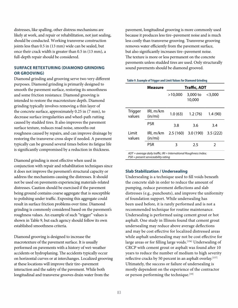
83
distresses, like spalling, other distress mechanisms are likely at work, and repair or rehabilitation, not just sealing, should be conducted. Working transverse construction joints less than 0.5 in (13 mm) wide can be sealed, but once their crack width is greater than 0.5 in (13 mm), a full-depth repair should be considered.
SURFACE RETEXTURING (DIAMOND GRINDING OR GROOVING) Diamond grinding and grooving serve two very different purposes. Diamond grinding is primarily designed to smooth the pavement surface, restoring its smoothness and some friction resistance. Diamond grooving is intended to restore the macrotexture depth. Diamond grinding typically involves removing a thin layer of the concrete surface, approximately 0.25 in (7 mm), to decrease surface irregularities and wheel-path rutting caused by studded tires. It also improves the pavement surface texture, reduces road noise, smooths out roughness caused by repairs, and can improve drainage by restoring the transverse cross slope if needed. A pavement typically can be ground several times before its fatigue life is significantly compromised by a reduction in thickness.
Diamond grinding is most effective when used in conjunction with repair and rehabilitation techniques since it does not improve the pavement’s structural capacity or address the mechanisms causing the distresses. It should not be used on pavements experiencing materials-related distresses. Caution should be exercised if the pavement being ground contains coarse aggregate that is susceptible to polishing under traffic. Exposing this aggregate could result in surface friction problems over time. Diamond grinding is commonly considered based on the pavement’s roughness values. An example of such “trigger” values is shown in Table 9, but each agency should follow its own established smoothness criteria.
Diamond grooving is designed to increase the macrotexture of the pavement surface. It is usually performed on pavements with a history of wet-weather accidents or hydroplaning. The accidents typically occur on horizontal curves or at interchanges. Localized grooving at these locations will improve their tire–pavement interaction and the safety of the pavement. While both longitudinal and transverse grooves drain water from the
pavement, longitudinal grooving is more commonly used because it produces less tire–pavement noise and is much less costly than transverse grooving. Transverse grooving removes water efficiently from the pavement surface, but also significantly increases tire–pavement noise. The texture is more or less permanent on the concrete pavements unless studded tires are used. Only structurally sound pavements should be diamond grooved.
Slab Stabilization / UndersealingUndersealing is a technique used to fill voids beneath the concrete slab in order to reduce the amount of pumping, reduce pavement deflections and slab distresses (e.g., punchouts), and improve the uniformity of foundation support. While undersealing has been used before, it is rarely performed and is not a recommended technique for routine maintenance. Undersealing is performed using cement grout or hot asphalt. One study in Illinois found that cement grout undersealing may reduce above average deflections and may be cost effective for localized distressed areas while asphalt undersealing may not be cost effective for large areas or for filling large voids.[156] Undersealing of CRCP with cement grout or asphalt was found after 10 years to reduce the number of medium to high severity reflective cracks by 50 percent in an asphalt overlay.[157] Ultimately, the success or failure of undersealing is mostly dependent on the experience of the contractor or person performing the technique.[10]
Table 9. Example of Trigger and Limit Values for Diamond Grinding
Measure Traffic, ADT
>10,000 3,000 to 10,000
<3,000
Trigger values
IRI, m/km (in/mi) 1.0 (63) 1.2 (76) 1.4 (90)
3.8 3.6 3.4PSR
Limit values
IRI, m/km (in/mi)
2.5 (160) 3.0 (190) 3.5 (222)
3 2.5 2PSR
ADT = average daily traffic; IRI = International Roughness Index; PSR = present serviceability rating

84
CLEANOUT OR RETROFIT EDGE DRAINS Pavements are designed such that free water is drained from the structure. Often the pavement is designed and built with a drainage layer or blanket and longitudinal and transverse drains. Cleanout of the edge drains must be regularly completed to assure that water does not lead to premature CRCP distresses. If the CRCP is experiencing excessive moisture in the pavement structure, then retrofitted edge drains may need to be installed to prevent distresses such as pumping, erosion, or materials-related durability issues. These drains, often a 4-in (100-mm) perforated pipe or a geotextile,[10] can more effectively evacuate the water from the pavement structure. While studies have found that retrofitted edge drains remove water from the pavement structure, not all studies have found that this prevented further pavement distresses.[10]
RepairDepending on the type and severity of the distress, a number of repair techniques are available, including full and partial-depth repairs, retrofitting tied concrete shoulders, and cross stitching. A repair is intended to restore as close as possible the original structural and/or functional capacity of the pavement.
RETROFIT WITH TIED CONCRETE SHOULDERS Installing tied concrete shoulders to the CRCP will reduce edge deflections, thereby reducing the probability of erosion and punchout formation. Sensitivity analysis with the AASHTO Pavement ME program has shown that the use of tied concrete shoulders relative to gravel or asphalt shoulders will reduce the number of predicted punchouts for a CRCP design,[59] as was shown in Figure 17. If a CRCP section is experiencing punchouts along the edge, then it may be necessary to consider installing tied concrete shoulders.
FULL-DEPTH REPAIR Full-depth repair (FDR) is used to repair severely deteriorated punchouts, joints, or cracks in CRCP when normal maintenance procedures can no longer correct them. They restore locally damaged areas to
near-original condition with similar smoothness and structural integrity. A limitation of FDRs is that they do not increase the pavement’s overall structural capacity. In rehabilitation projects, FDRs are typically the most prevalent and largest cost item. Because of this, many highway agencies tend to delay their installation. This delay leads to an increased rate of pavement deterioration and even more costly rehabilitation in the future. Ideally, FDRs should be constructed at the earliest appropriate time to be most cost effective, and to obtain the best long-term performance.
While FDRs primarily are used to repair punchouts in CRCP, they also can repair the following distresses:
• Wide transverse cracks (medium and high severity)
• Longitudinal cracks (high severity)• Localized distresses, like spalls, that extend
through more than one-third the slab thickness (medium and high severity)
• Blowups (low, medium and high severity)• Transverse cracks with high severity D-cracking
(as a stop-gap measure) • Deteriorated previous repairs (high severity)
FDRs are not considered a long-term solution for materials-related distresses such as ASR and D-cracking since the deterioration associated with these distresses will be widespread throughout the CRCP. Asphalt concrete patches are sometimes used as a temporary fix until a permanent concrete repair can be installed.[10] Asphalt patches should not be left in place as permanent patches, as these have been shown to perform poorly, even when used as a CRCP repair placed prior to an overlay.[157]
It is desirable to maintain the continuity of the longitudinal steel in the CRCP by tying it to the new steel in the FDR. Figure 67 demonstrates the procedure that can be used for sawing the limits of the repair area utilizing both full-depth and partial-depth saw-cuts prior to jackhammering the

85
deteriorated concrete to expose protruding lengths of the longitudinal steel in the CRCP. Following removal of the fractured concrete the new steel in the FDR can be connected to the protruding steel using tie wires, as shown in Figure 68.
A repair area prepared using the saw-cutting procedure described above and demonstrated in Figure 67 is shown prior to concrete removal in Figure 69. Additional photographs of the repair process are shown in Figures 70–72.
Figure 67. Full-depth and partial-depth saw-cuts made in CRCP prior to concrete removal.
Figure 68. New steel in FDR tied to longitudinal reinforcement protruding from CRCP.

86
The need for high-quality FDR construction cannot be overemphasized. Inadequate design, poor construction quality, and poor installation procedures will lead to premature failure of the FDR. Distresses commonly seen in FDRs include irregular transverse cracks, edge punchouts, longitudinal joint failure, pumping, and spalling. Distresses that can occur in the adjacent slab segments include spalling, wide cracks, edge punchouts, and blowups. The failure of a FDR and adjacent panels can be linked to a saturated base layer and/or poor compaction of the base layer prior to placing concrete. When the distress extends over multiple lanes, the lanes can be repaired independently by isolating the longitudinal joint with a fiber-board during construction. Also, while the transverse saw-cuts do not need to match across the lanes, small offsets should be avoided to prevent spalling at those locations. If a blowup occurs in the adjacent lane while placing the FDR, repair work for other locations should be delayed until cooler weather.
An alternate procedure used by TxDOT for making a FDR of CRCP is depicted in Figure 73. The procedure involves making full-depth transverse saw-cuts at the limits of the repair area, which typically is 6.0 ft (1.8 m) in length with a width that extends across either a
Figure 69. Full-depth and partial-depth saw-cuts at boundaries of CRCP repair area.
Figure 70. Longitudinal steel exposed in CRCP ready for splicing with new reinforcing steel.
Figure 71. New steel in FDR spliced to longitudinal steel exposed in CRCP.
Figure 72. Completed FDR in CRCP.

87
Figure 70. Longitudinal steel exposed in CRCP ready for splicing with new reinforcing steel.
Figure 71. New steel in FDR spliced to longitudinal steel exposed in CRCP.
Figure 72. Completed FDR in CRCP.
full lane-width or half of a lane-width. Following rapid removal of the distressed concrete, holes are drilled parallel to the longitudinal steel in the vertical faces of the CRCP. Tie bars are grouted in the holes with a sufficient length exposed for splicing the new steel in the FDR.
The South Carolina DOT utilizes jointed concrete with dowels for FDR of CRCP, as depicted in Figure 74. In this procedure, full-depth saw-cuts are made along the transverse and longitudinal limits of the FDR area. Following rapid removal of the distressed concrete, holes are drilled at mid-depth in the vertical faces of the CRCP parallel to the longitudinal steel. As noted in Figure 74, if the length of the repair exceeds 16.0 ft (4.9 m) then a dowel basket is placed at an intermediate location in the FDR. After placement of the repair concrete, a transverse contraction joint is sawed above the dowels in the basket. The depth of the saw-cut is equal to one-third of the thickness of the CRCP.
PARTIAL-DEPTH REPAIR A partial-depth repair (PDR) can be used for localized distresses, such as scaling, pop-outs, and spalling of
transverse cracks, in the upper one-third of the CRCP. PDRs are not appropriate if the deterioration extends below the upper third of the slab, in which case FDRs should be used. The Illinois DOT does not routinely use PDRs on CRCP, choosing instead to leave small spalls un-treated, and using asphalt in larger spalls as a temporary repair. TxDOT does regularly use PDRs for shallow spalls, defining shallow spalls as those having a depth of less than 4.0 in (100 mm).
Studies conducted by TxDOT concluded that shallow spalling can occur due to early-age delamination resulting from evaporation-induced stress gradients and shearing of concrete near the surface of the CRCP. [158] PDRs also are commonly used by various highway agencies prior to resurfacing with grinding, or before the application of an overlay.
CROSS-STITCHING AND SLOT-STITCHINGCross-stitching can be used to arrest the widening of longitudinal cracks or construction joints. Cross-stitching effectively prevents all vertical and horizontal movement. Deformed tie bars with a diameter of 0.75 in (19 mm) spaced at 20 to 30 in (500 to 700 mm) are grouted into holes drilled at 30 to 45 degrees to the pavement surface, as depicted in Figure 75.[110]
Slot-stitching also is used to prevent movement of longitudinal cracks and joints. Typically, tie bar lengths of 24.0 in (61 cm) are used with a spacing of 24.0 in (61 cm). As depicted in Figure 76, slot-stitching with deformed tie
Figure 73. Tie bars drilled into existing CRCP for splicing with new reinforcement in FDR (Texas).
Figure 74. Jointed concrete with dowels used for FDR of CRCP (South Carolina).

88
bars can be used to stabilize a longitudinal crack and to provide load transfer. Slot-stitching has been shown to be cost-effective for restoring load transfer at longitudinal cracks and joints, while cross-stitching is more effective for tying narrow cracks.[160]
OVERLAYS ON CRCP
Both rigid and flexible overlays can be placed to extend the service life of an existing CRCP. Proper resurfacing selection requires an understanding of the modes of
Figure 75. Cross-stitching a longitudinal crack.

89
failure that are occurring in the CRCP. Structural overlays are used when the existing pavement no longer provides the necessary level of service, either because the traffic loads have increased, its design life has been reached, or the CRCP has deteriorated extensively. Structural overlays typically are used when the preventative maintenance and restoration treatments are too expensive or are no longer cost effective at slowing down the rate of CRCP deterioration. Functional overlays with asphalt can be considered to improve the pavement ride quality and surface friction (skid resistance), conditions that directly affect road users.
Three structural overlay options for CRCP are: bonded concrete overlay (BCO), unbonded concrete overlay (UBCOL), and asphalt overlay. When resurfacing an existing CRCP, primary issues to consider in the overlay
selection process are constructability, performance life, cost-effectiveness, and suitability based on the condition of the existing pavement (Table 10). Additionally, the purpose of the overlay should be clearly defined, whether it is to provide mainly structural support, functional support, or both.
BCOs and UBCOLs can be either jointed concrete or CRCP. While the concepts discussed here for BCO and UBCOL apply to both, jointed concrete is the most common type of overlay for existing CRCP. Still, there have been a significant number of unbonded CRCP overlays, which are discussed in detail in Chapter 8.
Reflection cracking is one of the more predominate distresses that affect CRCP overlays when using either asphalt or bonded concrete overlays. Movement in
Figure 76. Slot-stitching a longitudinal crack with tie bars to stabilize and provide load transfer.

90
the underlying joints and cracks produces stress concentrations at the bottom of the overlay, directly above the discontinuities. Temperature changes produce thermal stresses, while traffic loadings produce shear and bending stresses at these locations. Reflection cracks propagate upward from the overlay interface, and eventually appear on the pavement surface. To reduce reflection cracking, several options are available. Fabrics, stress-relieving interlayers, stress-absorbing interlayers, and crack-arresting interlayers can be placed at the interface to physically arrest the reflection cracks. In addition, repairing the existing pavement can reduce the potential for reflection cracking.
Bonded Concrete Overlay of CRCPBCOs are an option for a CRCP that is in good condition but requires increased functional or structural capacity. BCOs provide a suitable riding surface and increase the structural capacity of the CRCP. It is the interfacial bond between the overlay and the underlying CRCP that allows them to act as a monolithic structure, which in turn increases the pavement structural capacity. While some BCOs have performed well for more than 20 years, their historical performance has been mixed.[161] This disparity can likely be attributed to variability in the interfacial bond strength and in the condition of the existing pavement. If the BCO is used on a properly
Table 10. Constructability, Performance, and Cost-Effectiveness of BCO, UBCOL, and AC Overlays of CRCP
BCO UBCOL AC Overlay of CRCP
Vertical clearance
Not a problem [typically 50 to 100 mm (2.0 to 4.0 in) thick]
May be a problem [typically 180 to 250 mm (7.0 to 10.0 in) thick]
May or may not be a problem; depends on overlay thickness
Traffic control May be difficult to construct under traffic
May be difficult to construct under traffic
Not difficult to construct under traffic
Construction Special equipment and experienced operators needed
No special equipment needed
No special equipment needed
Existing CRCP condition
Good condition with no materials-related distresses
All conditions (good to bad) Good condition, may accelerate materials-related distresses
Extent of repair Repair all deteriorated joints and cracks
Repair limited to severe damage
Repair all deteriorated joints and cracks
Future traffic Any traffic level Any traffic level Any traffic levelHistoric reliability
Fair to poor* Good Good
Initial Cost Depends on pre-overlay repairs, but usually high cost
Higher cost than conventional HMA overlay
Depends on the pre-overlay repairs
Life-cycle cost analysis
Competitive if future life is substantial
Competitive Cost effective unless the pavement is in poor condition
Typical life 15-25 years 20-30 years 10-15 years*Fair to poor performance attributed to placing BCOs on pavements not suitable for their use.
Cons
truc
tabi
lity
Perf
orm
ance
Cost
-Eff
ecti
vene
ss

91
selected project and well-constructed with good interfacial bond, it will last longer and provide a higher level of serviceability than will a conventional asphalt overlay. However, if the interface delaminates, the BCO performance will be reduced. BCOs also will not perform as intended if placed on CRCP that is too deteriorated or that has not been adequately repaired prior to resurfacing. The condition of the existing CRCP needs to be carefully evaluated for suitability prior to selecting a BCO as the method of choice. Texas and Iowa have been using BCOs to rehabilitate their concrete pavements since the 1970s.[162] Two BCOs of CRCP in Virginia showed good performance for being used to either increase the structural integrity of the pavement structure or to correct the effective depth of steel of the CRCP.[163]
A 2-in (50-mm) BCO was placed on CRCP on a section of I-295 around Richmond in 1995 to provide adequate cover for the longitudinal steel. Subsequently, in 2005, the BCO was overlaid with asphalt as part of a resurfacing project that included adjacent CRCP that had not received a BCO. Another BCO, on I-85 in Dinwiddie County, performed well for 20 years without any maintenance and subsequently was overlaid with asphalt as part of a major rehabilitation project on the I-85 corridor. In neither case was the condition or performance of the BCO the cause for the asphalt overlay. A 4-in (100-mm) BCO constructed in 2012 on U.S. 58 has not performed well and a repair contract was let in 2015. The comparison of performance among these BCO projects in Virginia serves to highlight the potential variability of this rehabilitation technique.
BCOs are very susceptible to reflection cracking, and nearly all cracks in the existing CRCP will eventually reflect through the overlay. Structural distresses in the existing CRCP should be repaired prior to placing a BCO to minimize their reflection. All distresses that compromise the CRCP load-carrying capacity or exacerbate reflection cracking should be repaired with FDRs, PDRs, slab stabilization, slab jacking, or cross stitching. If the existing pavement has evidence of materials-related distresses, a BCO should not be used.
Unbonded Concrete Overlay of CRCPUBCOLs are the most commonly placed concrete overlays. They are a long-term rehabilitation solution that can provide a level of service and performance comparable to that of newly constructed concrete pavements. UBCOLs are used when the existing CRCP is in fair to poor condition, but the overlay performs well because a separation layer is placed between the overlay and the underlying pavement. This separation layer makes the UBCOL relatively insensitive to the deficiencies in the existing pavement. The separation layer is designed to isolate the overlay from the underlying pavement, prevent or reduce the development of reflection cracks in the overlay, and provide uniform support to the overlay.[161]
The separation layer also provides friction and a certain amount of bonding between the UBCOL and the underlying pavement, which contributes to the composite behavior of the resulting pavement. Jointed concrete pavements are the most popular type of unbonded overlays—even for existing CRCP. Their thickness should be at least 6 to 11 in (150 to 280 mm). CRCP unbonded overlays should be at least 7 in (180 mm) or thicker for good performance. If the overlay has a thickness of less than 6 in (150 mm), it may not perform well.[161] UBCOLs significantly increase the thickness of the mainline pavement (Table 10). New shoulders, interchange ramps, and guardrails may need to be constructed as a result. This should be considered when assessing the economic feasibility of the UBCOL option.
For the most part, UBCOLs require fewer pre-overlay repairs than BCOs. But if severe distresses exist in the underlying pavement that will affect the overlay support, they should be completely repaired. Unbonded overlays that perform best have been found to have uniform support. This means that all distresses that deflect, or deform vertically, should be repaired. Punchouts and wide transverse cracks with significant differential deflection should be repaired to avoid their reflection through the overlay, and any unstable slab segments should be stabilized. Thicker separation layers can

92
be used to level out settlements and heaves and to fill severely spalled areas. UBCOLs are also applicable for existing pavements exhibiting materials-related distresses.
UBCOLs require an interlayer or separator layer to act as the bond breaker between the existing CRCP substrate and the concrete overlay. Dense-graded HMA is a common interlayer with good past performance, since it provides friction for crack development. Interlayers that have exhibited poor performance include polyethylene sheeting, chip seals, slurry seals, curing compound, and open-graded HMA, owing to issues with erodibility or stripping, they are not resistant to reflective cracks, and/or provide insufficient friction. While geotextiles have been used as the separator layer for UBCOLs of jointed concrete pavements, they have not yet been tested on CRCP. In general, thicker interlayers are needed for more severely distressed CRCP. In Virginia, an UBCOL constructed in 2012 on CRCP on U.S. 58 has performed extremely well. This UBCOL was built with exceptional ride quality.
Asphalt Overlay of Intact CRCP Asphalt overlays are a commonly used method for resurfacing CRCPs.[164] They are capable of increasing the functional characteristics (and possibly structural capacity) of existing CRCPs provided the existing pavement is somewhat structurally sound and preventive maintenance activities are still cost effective. Functional asphalt overlays typically have a thickness of 1.0 to 3.0 in (25 to 75 mm), while structural asphalt overlays are thicker, about 4.0 to 8.0 in (100 to 200 mm) or more. Thin asphalt overlays do not contribute significantly to the underlying pavement structural capacity, but they do provide the following benefits:
• They enhance the ride quality (reducing thedynamic impact loading) and can improve skidresistance if a problem exists.
• Asphalt overlays can be rapidly constructed.• Additional asphalt overlays can be used to provide
structural support when traffic volumes increase.
If the CRCP is in fair to good condition and only a few repairs need to be made, asphalt overlays can be used. However, the pavement should be resurfaced before the
number of distresses becomes significant. Punchouts, wide transverse cracks, spalled joints, and deteriorated cracks and repairs can reflect through the overlay and should be repaired with FDRs or PDRs. Prior to the application of an asphalt overlay, the CRCP should have no more than 5 to 10 punchouts per lane-mile (3 to 6 punchouts per lane-km), as a CRCP with more punchouts than this is likely experiencing significant fatigue damage and may require additional structural improvement prior to overlaying.[4] Also, any existing asphalt patches should be removed and repaired with concrete. As long as the repairs are made prior to overlay placement, reflection crack control methods are generally not necessary except along longitudinal joints. If the number of distresses is excessive, a different resurfacing option such as UBCOLs should be considered. Also, thin asphalt overlays should not be placed on concrete pavements with materials-related distresses.
RECONSTRUCTION
If the entire pavement structure requires reconstruction, then there are multiple options for what to do with the CRCP, including either crushing and removal or rubblization and use in-place. If the CRCP section is to be removed, then the only difference between CRCP and jointed concrete pavement is steel removal. Typically, the CRCP is broken in-place and the steel is removed with an excavator having a rake attachment. Once the steel is removed, the concrete can be loaded onto trucks and hauled away.
Rubblization is the process in which the CRCP is fractured in-place into pieces sized around 4 to 8 in (100 to 200 mm). This process destroys the structural capacity of the slab and dramatically decreases the LTE. However, rubblization offers a suitable base for placement of a new pavement. Highly distressed CRCP (e.g., excessive number of punchouts or severe materials-related distress) may be a good candidate for rubblization, since it may be more cost-effective than patching and/or overlaying.[165] In rubblized CRCP, the steel reinforcement needs to be cut and/or the concrete-to-steel bond needs to be broken; otherwise

93
movement in the rubblized section could result in reflection cracks in an overlay. One study found that a section of rubblized CRCP performed worse compared
to a section with rubblized jointed concrete pavement, possibly because the rubblized concrete was not fully de-bonded from the steel.[166]

94

95
CHAPTER 8 USE OF CRCP AS AN OVERLAY

96
UNBONDED AND BONDED CRCP OVERLAYS
While CRCP is often used for new construction, it also can be used as an overlay of existing pavement structures. The first CRCP overlay was constructed in Texas in 1959. Since then, CRCP overlays have been constructed in Arkansas, Connecticut, Georgia, Illinois, Indiana, Iowa, Maryland, Mississippi, North Dakota, Oregon, Pennsylvania, Texas and Wisconsin, with good performance.[167–169] Internationally, CRCP overlays have been constructed in Belgium, South Africa, South Korea and the United Kingdom.[147, 170–173] A 9-in (230-mm) unbonded CRCP overlay of an existing asphalt-overlaid pavement in Illinois was found to be more cost effective and structurally comparable to a 10-in (250-mm) jointed concrete pavement.[174] Illinois has reported satisfactory performance of unbonded CRCP overlays of jointed concrete pavements of up to 20 years.[175] Georgia has reported satisfactory performance of 30 years for a CRCP overlay of a jointed concrete pavement.[123] South Africa developed an ultra-thin CRCP overlay with a thickness of only 2.0 in (50 mm).[176]
As with any overlay scenario, no single option will meet all pavement design objectives. CRCP overlays are limited by their higher initial cost and more intensive construction activity; however, they offer long service lives with minimal maintenance.[167] Additional benefits of CRCP overlays are that reflective cracks may not be a critical issue if rehabilitation is timed correctly and smoothness of the pavement is retained.[168]
CRCP overlays are suitable for areas of high traffic, with some being constructed in areas with AADTT as high as 33,000.[169] The CRCP overlays used on the Ben Shoeman freeway in South Africa, parts of which can experience annual daily truck values as high as 150,000, have shown suitable performance after 20 years of service.[172]
The Illinois DOT has included CRCP overlays in several extended-life pavement designs. In 2002, a 10-mile (16-km) centerline section of I-70 in Clark County received an
unbonded CRCP overlay with a 30-year design life. The existing I-70 pavement was a 34-year-old CRCP section that had been overlaid with asphalt multiple times.[127] The asphalt overlays were milled to leave a 5-in (125-mm) depth of asphalt, which was overlaid with CRCP having a thickness of 12.0 in (300 mm). Unbonded CRCP overlays constructed in Illinois since 1967 are summarized in Table 11.
In 1997 in the United Kingdom, an unbonded CRCP overlay was used on the existing concrete pavement on the A449 roadway. For this project, a CRCP with a 40-year design life was constructed with a thickness of 250 mm (9.8 in) on a 5-mm (1.4-in) asphalt interlayer.[177] The existing concrete pavement was cracked and seated prior to the placement of the asphalt interlayer. Two-lift construction was employed for paving the CRCP overlay to facilitate the use of a select material for an exposed aggregate surface.
The Georgia DOT conducted a study in the 1970s in which CRCP was used as an overlay on two test sections where the existing jointed concrete was exhibiting severe faulting and cracking. Four overlay designs were constructed: a 3-in (75-mm) JRCP with woven wire mesh; 4.5-in (110 mm) CRCP with 0.6 percent steel; a 6.0-in (150 mm) CRCP with 0.6 percent steel; and a 6.0-in (150-mm) JPCP. The study concluded that the 6.0-in (150-mm) CRCP overlay with 0.6 percent steel should be used on sections with heavy traffic.[178]
UBCOLs are used when the existing pavement has significant deterioration (i.e., rutting, potholes, and alligator cracking for asphalt pavements and extensive cracking and faulting for concrete pavements).[179] A 1975 survey of 23 CRCP overlays in the U.S. revealed that the majority were unbonded overlays of existing concrete pavements, often utilizing an asphalt interlayer.[169] Figure 77 shows a 10.5-in (270 mm) unbonded CRCP overlay with 0.7% steel under construction. A white pigmented curing compound on the existing concrete pavement serves the dual function of reflecting heat and preventing bonding of the CRCP overlay.

97
STRUCTURAL DESIGN OF CRCP OVERLAYS
The AASHTO Pavement ME Design software can be used either for new CRCP alignments or for CRCP overlays of existing pavement structures. The software also can accommodate the addition of an asphalt interlayer. The percent longitudinal steel in a CRCP overlay is determined (selected) in the same way as for new CRCP construction. For unbonded CRCP overlays of concrete, it is recommended that some friction should be assumed to exist between the CRCP overlay and the asphalt interlayer. A slab-to-base friction coefficient of 7.5 is recommended
Table 11. Summary of Unbonded CRCP Overlays in Illinois
Year Location Overlay Details CRCP Overlay Thickness, in (mm)
Longitudinal Steel Content
1967 I-70 Existing 10.0-in (250 mm) jointed 6.0-in (150 mm) asphalt interlayer
8 (200) 0.6%7 (175) 0.7%6 (150) 1.0%
1970 I-55 (Springfield)
Existing 9.0-in (225 mm) jointed, 4.0-in (100 mm) asphalt interlayer on an 8.0-in (200 mm) asphalt overlay
8 (200) 0.6%
1974 I-55 (Springfield)
Existing 10.0-in (250 mm) jointed, 4.0-in (100 mm) asphalt interlayer
9 (225) 0.6%
1995 I-74 (Galesburg)
Existing 7.0-in (175 mm) CRCP, 3.0 to 4.5-in (75 to 112 mm) asphalt overlay
9 (225)
2000-2001 I-88 (Whiteside County)
Existing 8.0-in (200 mm) CRCP, 3.25-in (81 mm) asphalt overlay, 1.0-in (25 mm) leveling binder
9.25 (230)
2002 I-70 (Clark County)
Existing 8.0-in (200 mm) CRCP, 7.75-in (194 mm) asphalt overlay
12 (300) 0.8%
2011 I-57/I-64 (Mt. Vernon)
Existing 8.0-in (200 mm) CRCP (some sections rubblized), 3.0-in (75 mm) asphalt interlayer
10.5 (263)0.7%
Figure 77. Unbonded CRCP overlay under construction.

98
CRCP also can be designed as a bonded overlay of an existing concrete pavement structure; however, the underlying concrete needs to be in good condition. Some examples of bonded CRCP overlays of jointed concrete pavements can found in Texas,[9, 180] Iowa,[9] and South Korea.[171]
as a default friction coefficient for unbonded CRCP overlays of asphalt pavements. For a given CRCP overlay design, if the performance criteria are not met, then it is recommended that one or more of the following be considered until the criteria are met: increase the CRCP overlay thickness, increase the percent longitudinal steel, and/or add a tied concrete shoulder.[181]

99
CHAPTER 9 GUIDE SPECIFICATION FOR CRCP

100
2.1 COARSE AGGREGATE. The maximum size of coarse aggregate shall be not greater than one-half the minimum nominal clear opening between longitudinal reinforcing bars as computed from Project Plan dimensions.
2.2 CONCRETE STRENGTH LIMITS. The concrete strength shall be as designated in the Project Plans.
GUIDE NOTE: Plan concrete strengths should show values and test methods for either flexural or compressive with values at both 7 days and 28 days.
2.3 STEEL.
2.3.1 STEEL REINFORCING BAR SPECIFICATION. Reinforcing bars shall consist of deformed steel reinforcing bars and the material delivered to the site shall conform to one of the following requirements:
• Deformed common (black) reinforcing bars conforming to ASTM A615/A615M (AASHTO Designation M31M/M31) Grade 60.
• Deformed common (black) reinforcing bars conforming to ASTM A706/A706M Grade 60.
• Epoxy-coated reinforcing bars shall conform to ASTM A775/A775M. Epoxy-coated reinforcing bars shall be provided from a plant certified by CRSI in accordance with the CRSI Voluntary Certification Program for Fusion-Bonded Epoxy Coating Applicator Plants.
• Stainless-steel bar shall conform to ASTM A955/A955M Grade 60.
• Deformed reinforcing bars conforming to ASTM A1035/A1035M.
• Transverse Bar Assembly conforming to minimum W5 wire size number specified in ASTM A82/A82M for clips, minimum W2 wire size number specified in ASTM A82/A82M for chairs, and welded under Section 7.4 of ASTM A185/A185M.
• Transverse bars to which supports are to be welded, bars that cross the longitudinal joint, or bars which are to be bent and later straightened shall be ASTM A615/A615M Grade 40 or ASTM A706/A706M.
INTRODUCTION
This guide specification for field installation has been developed by the Concrete Reinforcing Steel Institute (CRSI) as part of their Cooperative Agreement with the Federal Highway Administration (FHWA). The guide specification was reviewed by various state DOTs, industry, and academia and is intended for educational purposes only. CRCP does not require transverse or transition joints except where necessary for construction purposes (e.g., end of day construction header joints) or in the approach to bridges or transitions to other pavement structures. Natural volume changes in the concrete (caused by hydration and seasonal movement), combined with the restraint imposed by steel reinforcement and the pavement base, will lead to transverse cracks that develop at regular intervals. These cracks, which occur as the pavement ages, are kept tight by the longitudinal reinforcement. These cracks are natural and intended and do not constitute defects. Longitudinal joints are used on CRCP to relieve concrete stresses in the transverse direction and/or when the paving cannot be performed in a single pass.
GUIDE SPECIFICATION1.0 DESCRIPTION. Work shall consist of constructing a continuously reinforced concrete pavement on a prepared subgrade or subbase in close conformity with the lines, grade, thicknesses, and typical cross-sections shown on the Project Plans and in accordance with the Standard Specifications except as modified herein.
All specification references shall be the latest copy at the time of bid release. Project plans shall include type of steel, spacing, etc.
2.0 MATERIALS. Materials shall conform to the requirements of the Standard Specifications, and the requirements given hereinafter.
• Coarse Aggregate• Protective Coatings• Steel Reinforcing Bars• Tie Bars• Steel Wide Flanges

101
reinforcing bar which is stored outdoors shall be off the ground, covered with tarpaulin and not in direct contact with steel storage racks or stored below steel bars. Non-ferrous cribbing shall separate the two materials.
3. CONSTRUCTION METHODS. The constructionof continuously reinforced concrete pavement shall conform in all respects to the requirements of the Standard Specifications with the following revisions and modifications.
3.1 PLACEMENT OF REINFORCING BARS. Reinforcing bars shall be preset such that the longitudinal bars shall be placed to meet the tolerances, locations and clearances shown on the Project Plans.
The arrangement and spacing of the supports shall be such that the reinforcing bars will be supported in proper position without permanent deflections or displacement of no more than 0.1 in (2.5 mm) occurring during the placement of the concrete in excess of the tolerances specified herein. They shall have sufficient bearing at the base to prevent overturning and penetration into the subbase. They shall be designed so as not to impede the placing and consolidation of the concrete or otherwise interfere with its performance. Continuous supports should not be set so close to other transverse bars as to make placing of the concrete between bars difficult.
This is particularly important in areas where there is a concentration of lap-spliced reinforcing bars. Welding of individual supports to transverse bars will be permitted.
GUIDE NOTE: It is not recommended to use tube feeding of reinforcing steel. While some state DOT specifications do allow it, it has been found that steel location is much too variable and can lead to excessive vertical and horizontal variations.
At the time the concrete is placed, the reinforcement shall be free of mud, oil or other non-metallic coating that may adversely affect or reduce the bond. Common (black) reinforcement with rust, seams, surface irregularities or mill scale shall be considered as satisfactory provided the weight, dimensions, cross-sectional area, and tensile properties of a hand wire brushed test specimen are not less than the applicable ASTM specification requirements.
• Wide flange beams if used in the anchor slabterminal joint of continuously reinforced pavementshall conform to the requirements of ASTM A36/A,36M or structural steel in ASTM A572/A 572M.
2.3.2 LENGTH OF REINFORCING BARS. The longitudinal bars shall be not less than 30 feet (10 m) in length except where shorter bars are required for the purpose of starting or ending a staggered lap pattern or at a construction joint. The maximum length of longitudinal bars shall be that which can be placed in a proper manner, or as shown on the Project Plans.
2.3.3 SIZE AND SPACING OF STEEL REINFORCING BARS. Longitudinal bars shall be of the dimensions and spacings as shown on the Project Plans or shall be governed by the minimum permissible spacing of the bars and the percentage of longitudinal steel specified or shown on the Project Plans. The longitudinal bars shall be spaced not less than 4 in (10 cm) and not more than 9 in (23 cm) center-to-center. Transverse bars shall be of the size, dimensions and spacings as shown on the Project Plans.
2.3.4 PROTECTING MATERIAL. Reinforcing steel shall be stored on platforms, skids, or other supports that will keep the steel above ground, well drained, and protected against deformation. When placed in the work, steel reinforcement shall be free from dirt, paint, oil, or other foreign substances.
2.3.5 BLACK BAR. Steel reinforcement with rust or mill scale will be permitted provided samples wire brushed by hand conform to the requirements for weight and height of deformation.
2.3.6 EPOXY-COATED BARS. Epoxy-coated bars shall be handled in accordance with Appendix X1 of ASTM A775 or Appendix X2 of ASTM A934.
2.3.7 STAINLESS STEEL. Stainless steel reinforcement shall be stored separately or above conventional steel reinforcing to prevent contamination from mill scale or other ferrous metals. Steel chains, bands and lifting devices should not be in direct contact with stainless. Synthetic straps and slings are preferred. Stainless steel

102
or epoxy-coated. Following placement of epoxy-coated reinforcement and prior to concrete placement, the reinforcement will be inspected. All visible damage of the epoxy coating shall be repaired in accordance with Appendix Xl of ASTM A775 or ASTM A934.
3.2 STEEL LOCATION CHECK PRIOR TO PAVING. The vertical location of the reinforcing steel shall be checked prior to concrete placement. This may be accomplished by pulling a string-line transversely across the roadway at the grade of the new pavement and measuring down to the reinforcing steel.
3.3 LAP SPLICES IN LONGITUDINAL REINFORCING BARS. Lap splices in the longitudinal reinforcing bars shall be placed in a pattern (skewed or staggered) across the pavement width as shown on the Project Plans. A minimum lap length of 25 bar diameters shall be used. No more than one-third of the longitudinal bars within a single traffic lane shall terminate in the same vertical plane at right angles to the pavement centerline. All lap splices in the longitudinal reinforcing bars shall be fastened securely with a minimum of two ties.
The longitudinal lap of all splices shall be checked to assure that the minimum lap of the reinforcing steel is maintained as shown in the Plan details.
GUIDE NOTE: The length of the lapped splices of the longitudinal reinforcing bars is critical to good performance. It is imperative that the minimum length requirements be observed carefully and enforced strictly during construction. If adequate bond strength is not developed in lap splices, wide cracks and subsequent failures will develop.
3.4 STEEL LOCATION CHECK DURING PAVING. A cover meter may be used to periodically check the depth of the reinforcing steel behind the paver while the concrete is plastic or hardened. Another option used to verify the depth of the reinforcing steel is to actually probe down to the reinforcing steel while the concrete is still plastic, and measure the depth.
Stainless steel should be protected from carbon steel surface contamination by using equipment exclusively dedicated to stainless steel, or by covering all contact points with clean neoprene, wood, or synthetic materials. If contamination of the stainless steel surface occurs it should be removed with a stainless steel wire brush or pickling paste. Bars shall be free from kinks or bends that may prevent proper assembly, placement or performance. Forms, if used, shall be oiled prior to placement of reinforcing bars.
A sample of the individual or continuous supports proposed for use shall be submitted for review. Unless a specific spacing of supports is designated on the Project Plans, a drawing showing the proposed layout with supports shall be developed and approved. If the support system does not maintain the reinforcing bars in the position required herein during placing and finishing of the concrete, the number of supports will need to be increased or steps taken as required to assure proper positioning of the reinforcing bars.
GUIDE NOTE: The Contractor may select the method of support to be used. However, if the required horizontal and vertical tolerances for placement of the reinforcing bars are not met, the Contracting Agency reserves the right to require changes in the placement or equipment operations.
Longitudinal bars shall be secured to the transverse bars by wire ties or clips at sufficient intersections to maintain the horizontal and vertical tolerances specified on the Project Plans. Welding of the longitudinal bars to the transverse bars shall not be permitted.
Steel reinforcement shall be firmly held during the placing and setting of concrete. Bars shall be tied at every intersection where the spacing is more than 12 in (305 mm) in any direction. Bars where the spacing is 12 in (305 mm) or less in each direction shall be tied at every intersection or at alternate intersections provided such alternate ties accurately maintain the position of steel reinforcement during the placing and setting of concrete. Stainless tie wires should be used for stainless steel. Tie wires used with epoxy-coated steel shall be plastic coated

103
3.6 FINAL STRIKE-OFF, CONSOLIDATION, AND FINISHING. The vibrating impulse shall be applied in a manner by which the concrete is consolidated throughout its entire depth and width. Special care shall be taken to assure thorough consolidation of the concrete under and around lapped bars to avoid segregation and honeycombing in the concrete. The pavement vibrator shall not be allowed to operate for more than 10 seconds while the machine is standing still. Only one pass of the vibrator equipment shall be made.
3.7 TRANSVERSE CONSTRUCTION JOINTS. A transverse construction joint shall be placed at the end of daily paving or whenever paving operations are interrupted for more than 30 minutes, provided the length of pavement laid from the last joint is 12.0 ft (3.5 m) or more and the distance from the construction joint to the nearest lap splice is at least 4.0 ft (1.2 m). Sections less than 12.0 ft (3.5 m) in length are not permissible.
At any location where a “leave out” is necessary for a detour, at least 100 ft (30.5 m) shall be maintained between transverse construction joints.
The transverse construction joint shall be formed by a split header board conforming to the cross-section of the pavement. The header shall consist of two sections, one being placed above and one being placed below the reinforcing mat, and shall be furnished with openings to accommodate the longitudinal steel. It shall be accurately set and held securely in place in a plane perpendicular to the surface of the pavement. The longitudinal reinforcing bars shall extend continuously through the split in the header board, supported beyond the joint by supports to prevent undue deflections, and afforded positive protection against excessive movement and bending until concrete placement resumes. A hand vibrator shall be used along the entire length of the joint. The header board shall be kept clean and not oiled.
The construction joint shall be strengthened by the addition of supplementary reinforcing bars of the same size, strength and type as the longitudinal bars. The supplementary bars shall be centered at the joint and at a uniform spacing along the joint as shown on the Project Plans. No lap splices in the longitudinal bars
3.5 PLACING AND PAVING OPERATION.Place, pave and finish concrete so as to: avoid segregation or loss of materials, avoid premature stiffening, produce a uniform dense and homogeneous product throughout the pavement, expel entrapped air and closely surround all reinforcement and embedded items, and provide the specified thickness and surface finish.
Extreme care should be exercised to prevent honeycombing in the concrete, especially around the immediate area of construction joints where hand spud vibrators shall be used to assure good consolidation of the concrete. The surface shall be given one pass for the full pavement width with a pan type or gang spud vibrator prior to the passage of the finishing machine.
GUIDE NOTE: Thickness measurements of the concrete slab can be determined by rod/level on a grid system, coring, or edge measurements.
For transverse bar reinforcement in a curve with a radius under 2,500 ft (762 m), the reinforcement shall be placed in a single continuous straight line across the lanes and aligned with the radius point. If the curve does not allow the specified spacing between transverse bar reinforcement and tie bars, space them a distance that is between one half the specified spacing and the specified spacing. The tie bars shall be placed on the same alignment as the transverse bar reinforcement.
Thickness Measurement — Under Thickness. A slab which is more than 0.50 in (13 mm) below the specified thickness shall be removed and replaced in accordance with the Standard Specifications. A slab which is 0.50 in (13 mm) or less below the specified thickness may be accepted providing that it represents isolated sections within a lot and such sections comprise less than 5 percent of the area of the lot. Such concrete shall be subject to a deduction in accordance with the Standard Specifications.
Thickness Measurement — Excess Thickness. Where the thickness of the slab exceeds the specified thickness, conformance of the slab is dependent on both thickness and strength. Deductions shall be applied in accordance with the Standard Specifications.

104
secured inside the holes using an approved non-shrink grout or chemical adhesive.
Monolithically placed slabs widths of more than 15 ft (4.5 m) shall have a longitudinal joint (contraction or construction). These joints shall be located within 6 in (15 cm) of the lane line unless the joint location is shown on the Project Plans.
Longitudinal joints shall be formed or sawed to a depth of one-third of the slab thickness. It is important that the reinforcing steel be placed and surveyed accurately in order to avoid conflict with the longitudinal sawn joint.
Longitudinal construction and contraction joints shall be cleaned and sealed in accordance with the contract specifications and Project Plans.
3.9 TERMINAL JOINTS. Terminal joints shall be constructed in accordance with details shown on the Project Plans.
• Terminal joints shall be constructed normal to the control line, to the dimensions and at the locations shown on the Project Plans or where directed by the Superintendent.
• Terminal joints shall extend over the full width of the base and the associated transverse expansion joint shall not be placed closer than 8.0 ft (2.4 m) to other transverse joints. Where necessary, the Superintendent shall authorize a change in the spacing of transverse joints to ensure that this minimum clearance is obtained.
• Excavation of trenches shall be to the dimensions and details shown on the Project Plans.
• The structural steel components and/or reinforcing steel shall be checked to assure they meet material requirements of the specifications and the details shown in the Project Plans.
• All surfaces that are required to be coated in the Project Plan details shall be done so completely.
3.9.1 LUG ANCHORAGE SYSTEM TERMINAL JOINT. The number and location of lugs shall be as shown on the Project Plans. The lugs shall be constructed in trench. All loose material shall be removed and the vertical
shall be within 4.0 ft (1.2 m) of the stopping side or closer than 8.0 feet (2.4 m) from the starting side of a construction joint.
Before paving operations are resumed, the header board shall be removed, any concrete that may have leaked through the holes or split in the header chipped away from the face of the joint, all surplus concrete on the subbase shall be cleaned away, and any irregularities in the subbase shall be corrected.
The fresh concrete shall be deposited directly against the old. Use hand-held immersion vibrators to consolidate the concrete adjacent to all formed joints. If more than 5 days elapse before construction continuation, the temperature of the completed slab shall be stabilized to reduce potential high tensile stresses in the longitudinal steel. This shall be accomplished by placing insulation material on the completed slab for a distance from the free end for a period of at least 72 hours prior to placing the adjacent concrete.
Tie bars located within 18 in (460 mm) of the transverse construction joint should be omitted.
Paving in the area of a transverse construction joint will not be permitted for 12 hours after installation.
3.8 LONGITUDINAL JOINTS. Longitudinal joints between adjacent slabs shall be tied together to prevent separation by using either tie bars of the type, length, size and spacing shown in the Project Plans, or transverse bars extending across the full width of each slab, as specified in the Project Plans.
For adjacent slabs constructed separately (i.e., construction joints), deformed tie bars, of the type, length, size and spacing shown in the Project Plans, shall be placed mid-depth and centered across the two slabs. These bars may be supported on approved assemblies or securely tied to the undersides of the longitudinal bars or placed manually or mechanically during the paving of the first slab or placed in preformed or drilled holes in the first slab after it has sufficiently hardened. Holes for the latter type of installation shall be blown clean and dry prior to placing the tie bars, and the bars shall be

105
of bituminous fiberboard or equivalent approved by the Superintendent and sealant shall comply with the necessary requirements. They shall be installed in accordance with the Project Plans and in a manner conforming to the manufacturer’s recommendations.
The surface of the pavement shall be finished in accordance with the Standard Specifications.
3.11 METHOD OF MEASUREMENT. Continuously reinforced concrete pavement shall be measured in square yards of pavement in place, completed and accepted. For this purpose, the width shall be that shown on the Project Plans. The area paid for shall be equal to the square yards of concrete pavement specified or required to be reinforced with no allowance for necessary lap splices.
3.12 BASIS FOR PAYMENT. This work shall be paid for at the contract unit price per square yard for Continuously Reinforced Concrete Pavement and Pavement Reinforcing Bars measured as specified herein. The unit price shall include the cost of bars, bar supports, wire, ties, clips, and all other accessories necessary for installing the reinforcing bars complete in place.
Terminal joints shall be paid for at the contract unit price per linear foot for the pavement width specified, which price shall include all excavation, concrete, reinforcement and all other appurtenances necessary to construct the lug system complete as shown on the plans.
SOURCES
This Guide Specification is based on specifications obtained from the states of California, Georgia, Illinois, Oklahoma, Oregon, Texas and Virginia. It also draws from a specification used by the Roads and Traffic Authority, New South Wales, Australia. The Guide Specification is in harmony with guidance provided in the Continuously Reinforced Concrete Pavement Manual, developed by the Federal Highway Administration under a Cooperative Agreement with the Concrete Reinforcing Steel Institute.
faces trimmed to neat lines. The bottom of the trench shall be re-compacted, where required, to the degree of consolidation of the adjacent undisturbed material and to the satisfaction of the Superintendent. The use of forms will not be permitted. Secure reinforcement in position before concrete placement in accordance with the Project Plans. Lug concrete shall be poured separately from the continuously reinforced concrete pavement. Membrane curing will not be permitted. The surface of the concrete shall be finished rough and shall be free of any dust, dirt or other foreign material at the time the continuously reinforced concrete pavement is placed.
3.9.2 WIDE FLANGE BEAM TERMINAL JOINT. Construct subgrade, base, and pavement layers in accordance with the Project Plans. Restore subgrade and base layers damaged by over-excavation. The sleeper slab shall be constructed to the same slope and cross section as the pavement. The top surface of the sleeper slab shall be given a smooth finish with a steel trowel on the pavement side of the wide flange beam and a rough finish on the terminal joint side. Membrane curing of the sleeper slab will not be permitted. Shop-fabricate wide-flange beams in accordance with the Plans. Unless otherwise shown on the Plans, wide-flange beams are not required to be welded or spliced at longitudinal construction joints. Accurately secure wide flange beam in position in accordance with the Project Plans and with sufficient supports to safely maintain alignment during concrete placement and finishing. The concrete in the groove on the expansion side of the wide flange beam shall be carefully finished across the top and at the edges of the pavement to facilitate unrestrained pavement expansion. The concrete on the fixed side shall be thoroughly vibrated to prevent voids occurring under the flange of the beam.
3.10 ISOLATION JOINTS. Isolation joints shall be provided at the locations and to the details shown on the Plans. The line of the isolation joint shall not deviatefrom the specified position by more than 0.5 in (10 mm). The line of the joint shall not deviate from a 10.0 ft (3 m) straight-edge by more than 0.5 in (10 mm). The joint filler shall consist of preformed jointing material

106

107
APPENDIX A: GLOSSARY
Aggregate Granular material, such as sand, gravel, crushed stone, crushed hydraulic-cement concrete, or iron blast furnace slag, used with a hydraulic cementing medium to produce either concrete or mortar.
Aggregate Interlock The projection of aggregate particles or portions of aggregate particles from one side of a joint or crack in concrete into recesses in the other side of the joint or crack facilitating load transfer in compression and shear and maintaining mutual alignment.
Air Content The amount of air in mortar or concrete, exclusive of pore space in the aggregate particles, usually expressed as a percentage of total volume of mortar or concrete.
Air Void A space in cement paste, mortar, or concrete filled with air; an entrapped air void is characteristically 0.4 in (1 mm) or more in size and irregular in shape; an entrained air void is typically between 3.93 x 10⁻⁴ and 0.39 in (0.01 mmand 1 mm) in diameter and spherical (or nearly so).
Air Entrained A system of minute bubbles of air in cement paste, mortar, or concrete during mixing.
Alkali-Aggregate Reaction (AAR) Chemical reaction in mortar or concrete between alkalis (sodium and potassium), which are released from cement or from other sources, and certain compounds present in the aggregates. Under certain conditions, harmful expansion of the concrete or mortar may be produced.
Alkali-Silica Reaction (ASR) The reaction between the alkalis (sodium and potassium) in cement and certain siliceous rocks or minerals, such as opaline chert, strained quartz, and acidic volcanic glass, present in some aggregates. The products of the reaction may cause abnormal expansion and cracking of concrete in service.
ACPA American Concrete Pavement Association
Anchor Lug End treatment installed at the end of CRCP sections to restrain the movement by transferring forces into the soil mass through the passive and shear resistance of the soil.
Area of Steel The cross-sectional area of the reinforcing bars in or for a given concrete cross section.
ASTM ASTM International (formerly American Society for Testing and Materials)
Bar Chair An individual supporting device used to support or hold reinforcing bars in proper position to prevent displacement before or during concreting.
Bar Spacing The distance between parallel reinforcing bars, measured center to center of the bars perpendicular to their longitudinal axis.
Base Support layer directly beneath the CRCP.
Bleeding The self-generated flow of mixing water within, or its emergence from, freshly placed concrete or mortar.
Bond The adhesion of concrete or mortar to reinforcement or other surfaces against which it is placed; the adhesion of cement paste to aggregate.
Bond Strength Resistance to separation of mortar and concrete from reinforcing steel and other materials with which it is in contact; a collective expression for all forces such as adhesion, friction due to shrinkage, and longitudinal shear in the concrete engaged by the bar deformations that resist separation.
Bond Stress The force of adhesion per unit area of contact between two surfaces such as concrete and reinforcing steel or any other material such as foundation rock.

108
Bonded Concrete Overlay (BCO) Overlay were the concrete surface is physically and chemically bonded to the underlaying pavement layer.
Coefficient of Thermal Expansion (CTE) Change in linear dimension per unit length or change in volume per unit volume per degree of temperature change. Compressive Strength The measured resistance of a concrete or mortar specimen to axial loading; expressed as pounds per square in (psi) or mega-pascals (MPa) of cross-sectional area.
Concrete See portland cement concrete.
Concrete Overlay New concrete placed onto existing concrete pavement. See also Bonded Concrete Overlay, Unbonded Concrete Overlay.
Consistency The relative mobility or ability of fresh concrete or mortar to flow. The usual measures of consistency are slump or ball penetration for concrete and flow for mortar.
Consolidation The process of inducing a closer arrangement of the solid particles in freshly mixed concrete or mortar during placement by the reduction of voids, usually by vibration, centrifugation, tamping, or some combination of these actions; also applicable to similar manipulation of other cementitious mixtures, soils, aggregates, or the like.
Construction Joint A joint made necessary by a prolonged interruption in the placing of concrete.
Continuously Reinforced Concrete Pavement (CRCP) Portland cement concrete pavement with no transverse joints and containing longitudinal steel in an amount designed to ensure holding shrinkage cracks tightly closed. Joints exist only at construction joints and on-grade structures.
CRSI Concrete Reinforcing Steel Institute
Crossover Leave-in or leave-out where CRCP intersects a roadway or haul road.
Cross Stitching Tying together premature cracks to promote a small crack width and high shear load transfer.
Curing Control of moisture content in concrete to facilitate hydration and development of desired strength and durability.
Curing Blanket A built-up covering of sacks, matting, Hessian, straw, waterproof paper, or other suitable material placed over freshly finished concrete.
Curing Compound A liquid that can be applied as a coating to the surface of newly placed concrete to retard the loss of water or, in the case of pigmented compounds, also to reflect heat so as to provide an opportunity for the concrete to develop its properties in a favorable temperature and moisture environment.
Deformed Bar A reinforcing bar with a manufactured pattern of surface ridges that provide a locking anchorage with surrounding concrete.
Drainage The interception and removal of water from, on, or under an area or roadway; the process of removing surplus ground or surface water artificially; a general term for gravity flow of liquids in conduits.
Durability The ability of concrete to remain unchanged while in service; resistance to weathering action, chemical attack, and abrasion.
Early Strength Strength of concrete developed soon after placement, usually during the first 72 hours.
FHWA Federal Highway Administration
Final Set A degree of stiffening of a mixture of cement and water greater than initial set, generally stated as an empirical value indicating the time in hours and minutes required for a cement paste to stiffen sufficiently to resist to an established degree, the penetration of a weighted test needle; also applicable to concrete and mortar mixtures with use of suitable test procedures. See also Initial Set.

109
Finishing Leveling, smoothing, compacting, and otherwise treating surfaces of fresh or recently placed concrete or mortar to produce desired appearance and service.
Fixed-Form Paving A type of concrete paving process that involves the use of fixed forms to uniformly control the edge and alignment of the pavement.
Flexural Strength See Modulus of Rupture.
Floating Process of using a tool, usually wood, aluminum, or magnesium, in finishing operations to impart a relatively even but still open texture to an unformed fresh concrete surface.
Grinding Area removal of maximum 0.16 to 0.24 in (4 to 6 mm) of concrete surface irregularities to promote smoothness.
Grooving The process used to cut slots into a concrete pavement surface to provide channels for water to escape beneath tires and to promote skid resistance.
Hairline Cracking Barely visible cracks in random pattern in an exposed concrete surface which do not extend to the full depth or thickness of the concrete, and which are due primarily to drying shrinkage.
Hardening When cement is mixed with enough water to form a paste, the compounds of the cement react with water to form cementitious products that adhere to each other and to the intermixed sand and stone particles and become very hard. As long as moisture is present, the reaction may continue for years, adding continually to the strength of the mixture.
Honeycombing Concrete that, due to lack of the proper amount of fines or vibration, contains abundant interconnected large voids or cavities; concrete that contains honeycombs was improperly consolidated.
IMCP The Integrated Materials and Construction Practices (IMCP) for Concrete is a manual developed by the National Concrete Pavement Technology Center (CP Tech Center). The manual provides guidance and information on materials and construction practices for concrete pavements.[1]
Initial Set A degree of stiffening of a mixture of cement and water less than final set, generally stated as an empirical value indicating the time in hours and minutes required for cement paste to stiffen sufficiently to resist to an established degree the penetration of a weighted test needle; also applicable to concrete or mortar with use of suitable test procedures. See also Final Set.
Joint Natural man-made crack because of construction or expected concrete contraction or to isolate movement.
Jointed Plain Concrete Pavement (JPCP) Pavement containing enough joints to control all natural cracks expected in the concrete; steel tie bars are generally used at longitudinal joints to prevent joint opening, and dowel bars may be used to enhance load transfer at transverse contraction joints depending upon the expected traffic.
Jointed Reinforced Concrete Pavement (JRCP) Pavement containing some joints and embedded steel mesh reinforcement (sometimes called distributed steel) to control expected cracks; steel mesh is discontinued at transverse joint locations.
Keyway or Key Joint A recess or groove in one lift or placement of concrete which is filled with concrete of the next lift, giving shear strength to the joint.
Lap Splice Connection of two longitudinal reinforcing bars that are tied to transfer strain over a minimum distance.
Leave-In Area in CRCP section that requires casting concrete prior to paving the surrounding CRCP.
Leave-Out Area in CRCP section such as intersecting roadway that requires casting of concrete after paving the surrounding CRCP.
Load Transfer Efficiency (LTE) The ability of a joint or crack to transfer a portion of a load applied on side of the joint or crack to the other side of the joint or crack.

110
Longitudinal Cracking Pavement cracking predominantly parallel to the direction of traffic.
Longitudinal Joint A joint placed parallel to the long dimension of the pavement to control longitudinal cracking.
Longitudinal Reinforcement Reinforcement essentially parallel to the long axis of a concrete member or pavement.
Longitudinal Tine Surface texture achieved by a hand held or mechanical device equipped with a rake-like tining head that moves in a line parallel to the pavement centerline.
Longitudinal Profile The perpendicular deviations of the pavement surface from an established reference parallel to the lane direction, usually measured in the wheel tracks.
Maximum Size Aggregate The largest size aggregate particles present in sufficient quantity to affect properties of a concrete mixture.
Mechanistic-Empirical A design philosophy or approach wherein classical mechanics (physics) is used in conjunction with empirically derived relationships to accomplish the design objectives.
Membrane Curing A process that involves either liquid sealing compound (e.g., bituminous and paraffinic emulsions, coal tar cut-backs, pigmented and non-pigmented resin suspensions, or suspensions of wax and drying oil) or non-liquid protective coating (e.g., sheet plastics or “waterproof ” paper), both of which types function as films to restrict evaporation of mixing water from the fresh concrete surface.
Modulus of Elasticity The modulus of any material is a measure of the stress-strain behavior of the material.
Modulus of Rupture An indicator of tensile bending strength of concrete, is the maximum tensile stress at the bottom at rupture during a flexural test of a simply supported concrete beam. Modulus of Subgrade Reaction Westergaard’s modulus of subgrade reaction for use in rigid pavement design (the load in pounds per square in on a loaded area of the roadbed soil or subbase divided by the deflection in inches of the roadbed soil or subbase, psi/in).
Moisture Content of Aggregate The ratio, expressed as a percentage, of the weight of water in a given granular mass to the dry weight of the mass.
Non-Destructive Testing (NDT) A broad category of testing methods used to evaluate the pavement structure without producing damage. Some examples include ground penetrating radar, falling weight delfectometry, impact echo, and magnetic tomography.
Paving Train An assemblage of equipment designed to place and finish a concrete pavement.
Pavement Condition A quantitative representation of pavement distress at a given point in time.
Pavement Management The effective and efficient direction of the various activities involved in providing and sustaining pavements at a condition acceptable to the traveling public at the lowest life-cycle-cost.
Pavement Performance Measure of accumulated service provided by a pavement (i.e., the adequacy with which it fulfills its purpose). Often referred to as the record of pavement condition or serviceability over time or with accumulated traffic.
Pavement Rehabilitation Work undertaken to extend the service life of an existing facility. This includes placement of additional surfacing material and/or other work necessary to return an existing roadway, including shoulders, to a condition of structural or functional adequacy. This could include the complete removal and replacement of a portion of the pavement structure.
Pavement Structure A combination of subbase, base course, and surface course placed on a subgrade to support the traffic load and distribute it to the roadbed.
PCA Portland Cement Association

111
Percent Fines Amount, expressed as a percentage, of material in aggregate finer than a given sieve, usually the No. 200 (0.075 mm) sieve; also, the amount of fine aggregate in a concrete mixture expressed as a percent by absolute volume of the total amount of aggregate.
Performance-Related Specifications (PRS) Specifications that describe the desired levels of key materials and construction quality characteristics that have been found to correlate with fundamental engineering properties that predict performance. These characteristics (for example, strength of concrete cores) are amenable to acceptance testing at the time of construction.
Permeable Subbase Layer consisting of crushed aggregates with a reduced amount of fines to promote drainage and stabilized with portland cement or bituminous cement.
Placement, Concrete The process of placing and consolidating concrete; a quantity of concrete placed and finished during a continuous operation.
Portland Cement Concrete (PCC) A composite material that consists essentially of a binding medium (portland cement and water) within which are embedded particles or fragments of aggregate, usually a combination of fine aggregate and coarse aggregate.
Punchout In continuously reinforced concrete pavement, the area enclosed by two closely spaced (less than 3 ft or 1m) transverse cracks, a short longitudinal crack, and the edge of the pavement or longitudinal joint, when exhibiting spalling, shattering, or faulting. Also, area between Y cracks exhibiting this same deterioration.
Quality Assurance (QA) Planned and systematic actions by an owner or his representative to provide confidence that a product or facility meet applicable standards of good practice. This involves continued evaluation of design, plan and specification development, contract advertisement and award, construction, and maintenance, and the interactions of these activities.
Quality Control (QC) Actions taken by a producer or contractor to provide control over what is being done and what is being provided so that the applicable standards of good practice for the work are followed.
Random Cracking Uncontrolled and irregular fracturing of a pavement layer.
Reinforcement Steel embedded in a rigid slab to resist tensile stresses and detrimental opening of cracks.
Resilient Modulus A standardized measurement of the modulus of elasticity of roadbed soil or other pavement material. The resilient modulus is a function of the recoverable strain under repeated loading.
Rideability A subjective judgment of the comparative discomfort induced by traveling over a specific section of highway pavement in a vehicle.
Saw-cut A cut in hardened concrete utilizing diamond or silicone-carbide blades or discs.
Screed Construction equipment that serves to strike-off concrete to the proper elevation.
Seamless Pavement Continuity of reinforcing bars over a bridge structure.
Setting of Cement Development of rigidity of cement paste, mortar, or concrete as a result of hydration of the cement. The paste formed when cement is mixed with water remains plastic for a short time. During this stage it is still possible to disturb the material and remix without injury, but as the reaction between the cement and water continues, the mass loses its plasticity. This early period in the hardening is called the “setting period,” although there is not a well-defined break in the hardening process. See also Final Set, Initial Set.
Setting Time The time required for a specimen of concrete, mortar or cement paste, prepared and tested under standardized conditions, to attain a specified degree of rigidity. See also Final Set, Initial Set.
Shrinkage Cracking Cracking of a slab due to failure in tension caused by external or internal restraints as reduction in moisture content develops.
112
Skid Resistance A measure of the frictional characteristics of a surface.
Slab Jacking Lift of concrete slab that has differentially settled relative to adjacent pavement structure.
Slab Stabilization Injecting grout or other proprietary rapid hardening materials to strengthen weak foundation materials in situ.
Slip-form Paving A type of concrete paving process that involves extruding the concrete through a machine to provide a uniform dimension of concrete paving. Slump A measure of consistency of freshly mixed concrete, equal to the subsidence measured to the nearest 1/4-in (6 mm) of the molded specimen immediately after removal of the slump cone.
Spalling Shallow or deep shear failure of concrete because of a combination of poor bond strength of aggregate paste, concrete shrinkage, and incompressible entering joints and cracks.
Strain Deformations occurring over a certain length in the concrete or steel caused by the environment or mechanical loading.
Strength A generic term for the ability of a material to resist strain or rupture induced by external forces. See also Compressive Strength, Flexural Strength, Tensile Strength,.
Stress Intensity of internal force (i.e., force per unit area) exerted by either of two adjacent parts of a body on the other across an imagined plane of separation; when the forces are parallel to the plane, the stress is called shear stress; when the forces are normal to the plane the stress is called normal stress; when the normal stress is directed toward the part on which it acts it is called compressive stress; when it is directed away from the part on which it acts it is called tensile stress.
Strike-off To remove concrete in excess of that required to fill the form evenly or bring the surface to grade; performed with a straight-edged piece of wood or metal by means of a forward sawing movement or by a power operated tool appropriate for this purpose; also the name applied to the tool. See also Screed.
Surface Texture Degree of roughness or irregularity of the exterior surfaces of aggregate particles or hardened concrete.
Subgrade The top surface of a roadbed upon which the pavement structure and shoulders are constructed.
Subgrade, Improved Any course or courses of select or improved materials between the subgrade soil and the pavement structure.
Tensile Strength Maximum stress that a material is capable of resisting under axial tensile loading based on the cross-sectional area of the specimen before loading.
Terminal Joint Used in continuously reinforced concrete pavement at the end of a paving day or when paving is halted. Tie bar Deformed steel bar extending across a longitudinal joint in a rigid pavement to prevent separation of abutting slabs.
Transition Joint Used in continuously reinforced concrete pavement at other pavement or bridge structures.
Transverse Cracking Pavement cracking predominantly perpendicular to the direction of traffic.
Transverse Construction Joint End of the day joint formed by the construction process.
Transverse Reinforcement Bars that serve as chairs for longitudinal steel, may serve as reinforcement to hold premature longitudinal cracks tight, and may be used as reinforcement to tie adjacent construction or contraction joints.
Unbonded Concrete Overlay (UBCOL) Does not rely on bonding of concrete surface layer to the underlying pavement layer for the structural design but does have frictional contact between the concrete, separator layer, and existing pavement.
Undersealing Injection of flowable material that rapidly sets to fill voids under existing concrete pavement structures.
Vibration Energetic agitation of concrete produced by a mechanical oscillating device at moderately high frequency to assist consolidation.

113
Vibration, External Employs vibrating devices attached at strategic positions on the forms and is particularly applicable to manufacture of precast items and for vibration of tunnel-lining forms; in manufacture of concrete products, external vibration or impact may be applied to a casting table.
Vibration, Internal Employs one or more vibrating elements that can be inserted into the concrete at selected locations, and is more generally applicable to in-place construction.
Vibration, Surface Employs a portable horizontal platform on which a vibrating element is mounted.
Vibrator An oscillating device used to agitate and consolidate fresh concrete so as to eliminate gross voids, including entrapped air but no entrained air, and produce intimate contact with form surfaces and embedded materials.
Water-Cement Ratio The ratio of the amount of water, exclusive only of that absorbed by the aggregates, to the amount of cement in a concrete or mortar mixture; preferably stated as a decimal by weight.
Wide Flange Beam Joint Transition that isolates movement of the end of the CRCP section from another pavement or structure such as a bridge.

114

115
APPENDIX B: REFERENCES
[1] Integrated Materials and Construction Practices for Concrete Pavement: A State-of-the-Practice Manual, Report FHWA HIF-07-004, FHWA, Washington, D.C., 2006.[2] Concrete Reinforcing Steel Institute, Summary of CRCP Design and Construction Practices in the US, Research Series No. 8, CRSI, Schaumburg, 2001.[3] American Association of State Highway and Transportation Officials, AASHTO Guide for Design of Pavement Structures, AASHTO, Washington, D.C., 1993.[4] American Association of State Highway and Transportation Officials, Mechanistic-Empirical Pavement Design Guide, Interim Edition: A Manual of Practice, AASHTO, Washington, D.C., 2008.[5] S.D. Tayabji, D.G. Zollinger, G.T. Korovesis, P.J. Stephanos, J.S. Gagnon, Performance of Continuously Reinforced Concrete Pavements - Volume I: Summary of Practice and Annotated Bibliography, Report FHWA-RD-94-178, FHWA, Washington, D.C., 1998.[6] S.D. Tayabji, P.J. Stephanos, J.S. Gagnon, D.G. Zollinger, Performance of Continuously Reinforced Concrete Pavements: Volume II - Field Investigations of CRC Pavements, Report FHWA-RD-94-179, FHWA, Washington, D.C., 1998.[7] S.D. Tayabji, D.G. Zollinger, J.R. Vederey, J.S. Gagnon, Performance of Continuously Reinforced Concrete Pavements: Volume III - Analysis and Evaluation of Field Test Data, Report FHWA-RD-94-180, FHWA, Washington, D.C., 1998.[8] D.G. Zollinger, N. Buch, D. Xin, J. Soares, Performance of CRC Pavements: Volume VI - CRC Pavement Design, Construction and Performance, Report FHWA-RD-97-151, FHWA, Washington, D.C., 1999.[9] S. Sriraman, D.G. Zollinger, Performance of CRC Pavements: Volume IV - Resurfacings for CRC Pavements, Report FHWA-RD-98-100, FHWA, Washington, D.C., 1999.[10] J.S. Gagnon, D.G. Zollinger, S.D. Tayabji, Performance of Continuously Reinforced Concrete Pavements: Volume V - Maintenance and Repair of CRC Pavements, Report FHWA-RD-98-101, FHWA, Washington, D.C., 1998.[11] D.G. Zollinger, J. Soares, Performance of CRC Pavements: Volume VII - Summary, Report FHWA-RD-98-102, FHWA, Washington, D.C., 1999.[12] S.D. Tayabji, O. Selezneva, Y.J. Jiang, Preliminary Evaluation of LTPP Continuously Reinforced Concrete (CRC) Pavement Test Sections, Report FHWA-RD-99-086, FHWA, Washington, D.C., 1999.[13] O.I. Selezneva, D. Zollinger, M. Darter, Mechanistic Analysis of Factors Leading to Punchout Development for Improved CRCP Design Procedures, in: Proc. Seventh Int. Conf. Concr. Pavements, Orlando, 2001.[14] M. Elfino, C. Ozyildirim, R. Steele, CRCP in Virginia, Lessons Learned, in: Proc. Seventh Int. Conf. Concr. Pavements, Orlando, 2001.[15] A.J. Wimsatt, Concrete Pavement Design and Construction Practices by the Texas DOT, in: Proc. 5th Int. Conf. Concr. Pavement Des. Rehabil., Purdue University, 2001.[16] D. Peshkin, M. Darter, The Construction and Performance of Concrete Pavements Reinforced with Flexarm, in: Proc. 5th Int. Conf. Concr. Pavement Des. Rehabil., Purdue University, 1993.[17] M. Plei, S. Tayabji, Continuously Reinforced Concrete Pavement: Performance and Best Practices, Report FHWA-HIF-12-039, FHWA, Washington, D.C., 2012.[18] O. Selezneva, M. Darter, D. Zollinger, S. Shoukry, Characterization of Transverse Cracking Spatial Variability Using LTPP Data for CRCP Design, in: Compend. Pap. 82nd Annu. Meet. Transp. Res. Board, 2003.[19] B.F. McCullough, A. Abou-Ayyash, W.R. Hudson, J.P. Randall, Design of Continuously Reinforced Concrete Pavements for Highways, Final Report Research Project NCHRP 1-15, Transportation Research Board, Washington, D.C., 1975.
[20] B.F. McCullough, D. Zollinger, T. Dossey, Evaluation of the Performance of Texas Pavements Made with Different Coarse Aggregates, Report TX-01/7-3925-1, Texas Department of Transportation, 2000.[21] B.F. McCullough, J.C.M. Ma, C.S. Noble, Limiting Criteria for the Design of CRCP, Report FHWA/TX-79/21+177-17, Texas State Department of Highways and Public Transportation, 1979.[22] Y.H. Huang, Pavement Analysis and Design, 2nd ed., Prentice Hall, Upper Saddle River, 2004.[23] Y. Jung, D. Zollinger, A. Wimsatt, Test Method and Model Development of Subbase Erosion for Concrete Design, Transp. Res. Rec. 2154 (2010) 22–31.[24] D.G. Zollinger, S.P. Senadheera, T. Tang, Spalling of Continuously Reinforced Concrete Pavements, J. Transp. Eng. 120 (1994) 394–411.[25] L. Wang, D. Zollinger, Mechanistic Design Framework for Spalling Distress, Transp. Res. Rec. 1730 (2000) 18–24.[26] K. Folliard, D. Sutfin, R.P. Turner, D. Whitney, Fiber in Continuously Reinforced Concrete Pavements, Report FHWA/TX-07/0-4392-2, Texas Department of Transportation, Austin, 2006.[27] S.-M. Kim, M.C. Won, Horizontal Cracking in Continuously Reinforced Concrete Pavements, ACI Strucutral J. 101 (2004) 784–791.[28] L. Rens, A. Beeldens, P. De Winne, Recent Developments in the Design and Construction of CRCP Towards a More Durable Concept, in: Proc. 12th Int. Symp. Concr. Roads, Prague, Czech Republic, 2014.[29] J. Choi, H.L. Chen, Design Consideration of GFRP-Reinforced CRCP, in: ACI SP-215, F. Appl. FRP Reinfocement Case Stud., 2003: pp. 139–158.[30] J.-H. Choi, R.H.L. Chen, Design of Continuously Reinforced Concrete Pavements Using Glass Fiber Reinforced Polymer Rebars, Report FHWA-HRT-05-081, FHWA, Washington, D.C., 2005.[31] R.M. Larson, K.D. Smith, TechBrief: Evaluating the Use of Fiber-Reinforced Polymer Bars in Continuously Reinforced Concrete Pavement, FHWA-HIF-09-012, FHWA, Washington, D.C., 2009.[32] Y. Zhang, Z. Huang, J. Roesler, Crack Behavior in Asphalt Composite CRCP with Basalt Fiber Reinforcement, in: Proc. 11th Int. Conf. Concr. Pavements, San Antonio, Texas, 2016.[33] Guide for Mechanistic-Empirical Design of New and Rehabilitated Pavement Structures, Final Report Research Project NCHRP 1-37A, Transportation Research Board, Washington, D.C., 2004.[34] J.E. Burke, J.S. Dhamrait, A Twenty-Year Report on the Illinois Continuously Reinforced Pavement, Highw. Res. Rec. 239 (1968) 197–211.[35] S.D. Tayabji, P.J. Stephanos, D.G. Zollinger, Nationwide Field Investigation of Continuously Reinforced Concrete Pavements, Transp. Res. Rec. 1482 (1995) 7–18.[36] N.G. Gharaibeh, M.I. Darter, Probabilistic Analysis of Highway Pavement Life for Illinois, Transp. Res. Rec. 1823 (2003) 111–120.[37] K.D. Smith, M.J. Wade, D.G. Peshkin, L. Khazanovich, H.T. Yu, M.I. Darter, Performance of Concrete Pavements, Volume II: Evaluation of In-service Concrete Pavements, Report FHWA-RD-95-110, FHWA, Washington, D.C., 1998.[38] E. Kohler, J. Roesler, Accelerated Pavement Testing of Extended Life Continuously Reinforced Concrete Pavement Sections, Transportation Engineering Series No. 141, Illinois Cooperative Highway and Transportation Series No. 289, University of Illinois, Urbana, 2006.[39] S.A. LaCoursiere, M.I. Darter, S.A. Smiley, Construction of CRCP Pavement in Illinois, Technical Report FHWA-IL-UI-172, Illinois Department of Transportation, Springfield, 1978.[40] N.G. Gharaibeh, M.I. Darter, L.B. Heckel, Field Performance of Continuously Reinforced Concrete Pavement in Illinois, Transp. Res. Rec. 1684 (1999) 44–50.[41] D.G. Zollinger, E.J. Barenberg., Continuously Reinforced Pavements: Punchout and Other Distresses and Implications for Design, Report FHWA/IL/UI 227; Project IHR–518, Illinois Cooperative Highway Research Program, University of Illinois at Urbana-Champaign, 1990.[42] J. Dhamrait, F. Jacobsen, P. Dierstein, Construction Experience with CRC Pavements in Illinois, Report FHWA-IL-PR-55; Physical Research No. 55, Illinois Department of Transportation, Springfield, 1977.[43] R.O. Rasmussen, R. Rogers, T.R. Ferragut, Continuously Reinforced Concrete Pavement: Design and Construction Guidelines, FHWA, Washington, D.C., 2009.

116
[44] O. Selezneva, C. Rao, M. Darter, D. Zollinger, L. Khazanovich, Development of a Mechanistic-Empirical Structural Design Procedure for Continuously Reinforced Concrete Pavements, Transp. Res. Rec. 1896 (2004) 46–56.[45] Applied Research Associates, Guide for Mechanistic-Empirical Design of New and Rehabilitated Pavement Structures, Appendix LL: Punchouts in Continuously Reinforced Concrete Pavements (NCHRP 1-37A), ARA, Champaign, Illinois, 2003.[46] C. Rao, M. Darter, Enhancements to the Punchout Prediction Model in the MEPDG Design Procedure, in: Compend. Pap. 92nd Annu. Meet. Transp. Res. Board, Transportation Research Board, Washington, D.C., 2013. http://docs.trb.org/prp/13-5249.pdf.[47] J. Dhamrait, D. Schwartz, Effect of Subbase Type and Subsurface Drainage on Behavior of CRC Pavements, Report FHWA-IL-PR-83; Physical Research No. 83, Illinois Department of Transportation, Springfield, 1978.[48] A.K. Schindler, B.F. McCullough, Importance of Concrete Temperature Control During Concrete Pavement Construction in Hot Weather Conditions, Transp. Res. Rec. 1813 (2002) 3–10.[49] American Concrete Pavement Association, The Concrete Pavement Restoration Guide, Technical Bulletin TB-020P, ACPA, Skokie, 1997.[50] Applied Research Associates, Guide for Mechanistic-Empirical Design of New and Rehabilitated Pavement Structures, Appendix PP: Smoothness Predictions for Rigid Pavements (NCHRP 1-37A), ARA, Champaign, Illinois, 2001.[51] K.D. Hall, S. Beam, Estimating the Sensitivity of Design Input Variables for Rigid Pavement Analysis with a Mechanistic-Empirical Design Guide, Transp. Res. Rec. 1919 (2005) 65–73.[52] V. Kannekanti, J.T. Harvey, Sensitivity Analysis of 2002 Design Guide Distress Prediction Models for Jointed Plain Concrete Pavement, Transp. Res. Rec. 1947 (2006) 91–100.[53] T. Freeman, J. Uzan, D. Zollinger, E.S. Park, Sensitivity Analysis and Strategic Plan Development for the Implementation of the ME Design Guide in TxDOT Operations, Report FHWA/TX-05/0-4714-1, FHWA, Washington, D.C., 2005.[54] M. Won, Evaluation of MEPDG with TxDOT Rigid Pavement Database, Report FHWA/TX-09/0-5445-3, Center for Transportation Research, University of Texas at Austin, 2009.[55] A. Bordelon, J.R. Roesler, J.E. Hiller, Mechanistic-Empirical Design Concepts for Jointed Plain Concrete Pavements in Illinois, Final Report FHWA-ICT-09-052, Illinois Center for Transportation, University of Illinois, Urbana, 2009.[56] C. Schwartz, S.H. Kim, H. Ceylan, K. Gopalakrishnan, Sensitivity Evaluation of MEPDG Performance Prediction (NCHRP 1-47), Transportation Research Board, Washington, D.C., 2011.[57] J.M. Vandenbossche, S. Nassiri, L.C. Ramirez, J. Sherwood, Evaluating the Continuously Reinforced Concrete Pavement Performance Models of the Mechanistic-Empirical Pavement Design Guide, Road Mater. Pavement Des. 13 (2012) 235–248.[58] T. Ley, A. Hajibabbee, S. Kadam, R. Frazier, M. Aboustait, T. Ebisch, et al., Development and Implementation of a Mechanistic and Empirical Pavement Design Guide (MEPDG) for Rigid Pavements–Phase I, Final Report FHWA-OK-12-08, Oklahoma State University, Stillwater, 2013.[59] J. Roesler, J.E. Hiller, Continuously Reinforced Concrete Pavement: Design Using the AASHTOWare Pavement ME Design Procedure, Report FHWA-HIF-13-025, FHWA, Washington, D.C., 2013.[60] G. Markeset, S. Rostam, O. Klinghoffer, Guide for the Use of Stainless Steel Reinforcement in Concrete Structures, Project Report 405, Norwegian Building Research Institute, Oslo, 2006.[61] J.K. Cable, L.L. McDaniel, Demonstration and Field Evaluation of Alternative Portland Cement Concrete Pavement Reinforcement Materials, Final Report Iowa DOT Project HR-1069, Iowa State University, Ames, 1998.[62] D.G. Zollinger, A. McKneely, J. Murphy, T. Tang, Analysis of Field Monitoring Data of CRC Pavements Constructed with Grade 70 Steel, Report TX-99/4925-1, Texas Department of Transportation, 1999.[63] Continuously Reinforced Concrete Pavements, Permanent International Association of Road Congresses, Paris, 1994.[64] Concrete Reinforcing Steel Institute, Using Soft Metric Reinforcing Bars in Non-Metric Construction Projects, Report No. 42, CRSI, Schaumburg, 1997.
[65] M.J.A. Stet, A.J. van Leest, CRCP: A Long-Lasting Pavement Solution for Todays Motorways, the Dutch Practice, in: Proc. 7th Int. Conf. Concr. Pavements, 2001.[66] L. Rens, A. Beeldens, The Behaviour of CRCP in Belgium: Observation and Measurement of Crack Pattern, Bond and Thermal Movement, in: Proc. 7th Int. Work. Des. Perform. Sustain. Durable Concr. Pavements, Sevilla, Spain, 2010.[67] D. Zollinger, M. Won, T. Ley, K. Riding, A. Wimsatt, W. Zhou, et al., Implementation of Curing, Texturing, Subbase, and Compaction Measurement Alternatives for Continuously Reinforced Concrete Pavement, Report 5-6037-01-1, Texas Transportation Institute, College Station, 2014.[68] ERES Consultants, Pavement Subsurface Drainage Design—Reference Manual, FHWA, Washington, D.C., 1999.[69] R.J. Roman, M.I. Darter, Pavement Distress Study I-77, Fairfield and Chester Counties, South Carolina, Technical Report submitted to South Carolina Department of Highways and Public Transportation, ERES Consultants, 1988.[70] D. Birmann, Erosion of Cement Treated Subbases Below Concrete Pavement, in: Proc. from 8th Int. Symp. Concr. Roads, Theme III: Pavement Performance and Evaluation, Lisbon, Portugal, 1998.[71] T.E. Hoerner, M.I. Darter, L. Khazanovich, L. Titus-Glover, K.L. Smith, Improved Prediction Models for Concrete Pavement Performance-Related Specifications, Volume I: Final Report FHWA-RD-00-130, FHWA, Washington, D.C., 2000.[72] H.T. Yu, L. Khazanovich, S. Rao, M.I. Darter, H.V. Quintus, Guidelines for Subsurface Drainage Based on Performance, Final Report NCHRP 1-34, Transportation Research Board, Washington, D.C., 1999.[73] L. Heckel, Performance Problems of Open-Graded Drainage Layers Under Continuously Reinforced Concrete Pavements in Illinois, Transp. Res. Rec. 1596 (1997) 51–57.[74] E.J. Yoder, M.W. Witczak, Principles of Pavement Design, John Wiley and Sons, 1975.[75] Applied Research Associates, Guide for Mechanistic-Empirical Design of New and Rehabilitated Pavement Structures (NCHRP 1-37A), Appendix SS: Hydraulic Design, Maintenance, and Construction Details of Subsurface Drainage Systems, Transportation Research Board, Washington, D.C., 2001.[76] A.K. Schindler, T. Dossey, B.F. McCullough, Temperature Control During Construction to Improve the Long Term Performance of Portland Cement Concrete Pavements, Report FHWA/TX-05/0-1700-2, Texas Department of Transportation, Austin, 2002.[77] Federal Highway Administration, Traffic Monitoring Guide, Third Edition (FHWA-PL-95-031), FHWA, Washington, D.C., 1995.[78] Federal Highway Administration, Continuously Reinforced Concrete Pavement, Technical Advisory T 5080.14, FHWA, Washington, D.C., 1990.[79] Design Manual for Roads and Bridges, Pavement Design, HD 26/01, United Kingdom, 2001.[80] S. Rao, M. Darter, D. Tompkins, M. Vancura, L. Khazanovich, J. Signore, et al., Composite Pavement Systems Volume 1: HMA/PCC Composite Pavements, SHRP2 Report S2-R21-RR-2, Transportation Research Board, Washington, D.C., n.d.[81] Z. Mao, Life-Cycle Assessment of Highway Pavement Alternatives in Aspects of Economic, Environmental, and Social Performance, MS Thesis, Texas A&M University, College Station, 2012.[82] E.C. Ferrebee, Development of the Materials, Construction, and Maintenance Phases of a Life Cycle Assessment Tool for Pavements, MS Thesis, University of Illinois, Urbana, 2014.[83] J. Harvey, J. Meijer, A. Kendall, TechBrief: Life Cycle Assessment of Pavements, FHWA-HIF-15-001, FHWA, Washington, D.C., 2014.[84] J. Walls III, M.R. Smith, Life-Cycle Cost Analysis in Pavement Design - Interim Technical Bulletin, Report FHWA-SA-98-079, FHWA, Washington, D.C., 1998.[85] T.U. Mohammed, H. Hamada, Corrosion of Steel Bars in Concrete with Various Steel Surface Conditions, ACI Mater. J. 103 (2006) 233–242.[86] M. Won, K. Hankins, B.F. McCullough, Mechanistic Analysis of Continuously Reinforced Concrete Pavements Considering Material Characteristics, Variability, and Fatigue, Report No. FHWA/TX-92+1169-2, Texas State Department of Highways and Public Transportation, 1991.

117
[87] M.A. Otero, B.F. McCullough, K. Hankins, Monitoring of Siliceous River Gravel and Limestone Continuously Reinforced Concrete Pavement Test Sections in Houston 2 Years After Placement, and Development of a Crack Width Model for the CRCP-7 Program, Report FHWA/TX-92+1244-4, Texas Department of Transportation, 1992.[88] Concrete Reinforcing Steel Institute, Design and Construction, Continuously Reinforced Concrete Pavement, Continuously Reinforced Pavement Group, Chicago, 1968.[89] H.A. Lepper, J.B. Kim, Tests of Reinforcement Splices for Continuously Reinforced Concrete Pavement, Highw. Res. Rec. 60 (1964).[90] M.I. Darter, H. Von Quintus, Y.J. Jiang, E.B. Owusu-Antwi, B.M. Killingsworth, Catalog of Recommended Pavement Design Features, NCHRP Final Report Project 1-32, Washington, D.C., 1997.[91] Associated Reinforced Bar Producers - CRSI, Design of Continuously Reinforced Concrete for Highways, 1981.[92] J.S. Dhamrait, R.K. Taylor, Behavior of Experimental CRC Pavements in Illinois, Technical Report No. FHWA- IL-PR-82, Illinois Department of Transportation, Springfield, 1979.[93] B.F. McCullough, T. Dossey, Controlling Early-Age Cracking in Continuously Reinforced Concrete Pavement: Observations from 12 Years of Monitoring Experimental Test Sections in Houston, Texas, Transp. Res. Rec. 1684 (1999) 35–43.[94] American Concrete Pavement Association, Fast Track Concrete Pavements, TB004P, ACPA, Skokie, 1994.[95] J. Schlitter, R. Henkensiefken, J. Castro, K. Raoufi, J. Weiss, Development of Internally Cured Concrete for Increased Service Life, Report FHWA/IN/JTRP-2010/10, Indiana Department of Transportation, Indianapolis, 2010.[96] A. Amirkhanian, J. Roesler, Curling Behavior of Concrete Beams with Fine Lightweight Aggregates, in: Proc. 11th Int. Conf. Concr. Pavements, San Antonio, Texas, 2016.[97] C. Rao, M.I. Darter, Evaluation of Internally Cured Concrete for Paving Applications, ARA, Champaign, Illinois, 2013.[98] A.L. Correa, B. Wong, Concrete Pavement Rehabilitation - Guide for Diamond Grinding, Report FHWA-SRC-1/10-01(SM), FHWA, Washington, D.C., 2001.[99] R.W. Perera, S.D. Kohn, S. Tayabji, Achieving a High Level of Smoothness in Concrete Pavements Without Sacrificing Long-Term Performance, Report FHWA-HRT-05-068, FHWA, Washington, D.C., 2005.[100] S.D. Tayabji, C.L. Wu, M. Plei, Performance of Continuously Reinforced Concrete Pavements in the LTPP Program, in: Proc. 7th Int. Conf. Concr. Pavements, 2001: pp. 685–700.[101] M.G. Grogg, K.D. Smith, PCC Pavement Smoothness: Characteristics and Best Practices for Construction, Report FHWA-IF-02-025, FHWA, Washington, D.C., 2002.[102] American Concrete Pavement Association, Constructing Smooth Concrete Pavements, TB-006.0-C, ACPA, Skokie, 2003.[103] Z. Siddique, M. Hossain, W. Parcells, Effect of Curing on Roughness Development of Concrete Pavements, J. Mater. Civ. Eng. 19 (2007) 575–582.[104] Q. Xu, J.M. Ruiz, G.K. Chang, J.C. Dick, S.I. Garber, R.O. Rasmussen, Computer-Based Guidelines for Concrete Pavements: HIPERPAV® III User Manual, Report FHWA DTFH61-99-C-00081, FHWA, McLean, 2009.[105] S. Rao, J.R. Roesler, Characterization of Effective Built-in Curling and Concrete Pavement Cracking on the Palmdale Test Sections, Research Report UCPRC-RR-2005-09, Institute of Transportation Studies, University of California, Davis, 2005.[106] Work Zone Operations Best Practices Guidebook, Third Edition, Report FHWA-HOP-13-012, FHWA, Washington, D.C., 2013.[107] Manual on Uniform Traffic Control Devices, Revised 2009 Edition, FHWA, Washington, D.C., 2012.[108] J. Mallela, A. Gotlif, M.I. Darter, A. Ardani, P. Littleton, Mechanistic-Empirical Tie Bar Design Approach For Concrete Pavements, Report to American Concrete Pavement Association, 2009.[109] ACPT, CRCP: Improved Transition Designs, TechBrief, FHWA-HIF-13-026, FHWA, Washington, D.C., 2013.[110] American Concrete Pavement Association, Stitching Concrete Pavement Cracks and Joints, SR903P, ACPA, Skokie, 2001.
[111] Y. Jung, D.G. Zollinger, S.D. Tayabji, Best Practices of Concrete Pavement Transition Design and Construction, Research Report 0-5320-1, Texas Transportation Institute, College Station, Texas, 2006.[112] D. Zollinger, Y. Jung, TechBrief: Continuously Reinforced Concrete Pavement: Improved Transition Designs, Report FHWA-HIF-13-026, FHWA, McLean, 2013.[113] Concrete Reinforcing Steel Institute, Continuously Reinforced Concrete Pavement for Highways, CRC Construction Manual, CRSI, 1983.[114] Design of Terminals for Rigid Pavements to Control End Movements: State of the Art, Special Report 173, Transportation Research Board, Washington, D.C., 1977.[115] B.F. McCullough, F. Herber, A Report on Continuity Between a Continuously Reinforced Concrete Pavement and a Continuous Slab Bridge, Report No. 39-3, Texas Highway Department, 1966.[116] S. Griffiths, G. Bowmaker, C. Bryce, R. Bridge, Design and Construction of Seamless Pavement on Westlink M7, Sydney, Australia, in: Proc. 8th Int. Conf. Concr. Pavements, Colorado Springs, Colorado, 2005: pp. 21–38.[117] Federal Highway Administration, Paved Shoulders, Technical Advisory T 5040.29, FHWA, Washington, D.C., 1990.[118] E.R. Kohler, J.R. Roesler, Active Crack Control for Continuously Reinforced Concrete Pavements, Transp. Res. Rec. 1900 (2004) 19–29.[119] G.J. Fick, Testing Guide for Implementing Concrete Paving Quality Control Procedures, FHWA, Washington, D.C., 2008.[120] J. Grove, G. Fick, T. Rupnow, F. Bektas, Material and Construction Optimization for Prevention of Premature Pavement Distress in PCC Pavements, Pooled Fund Study TPF-5(066), FHWA, Washington, D.C., 2008.[121] Concrete Reinforcing Steel Institute, Field Inspection of Reinforcing Bars, Engineering Data Report No. 54, CRSI, Schaumburg, 2004.[122] T.E. Stanton, Reports on Experiments with Continuous Reinforcement in Concrete Pavements - California, Proc. Thirtieth Annu. Meet. Highw. Res. Board. 30 (1951) 28–44.[123] CRCP in Georgia, Case History Report No. 61, CRSI, Schaumburg, 2003.[124] CRCP — The Illinois Experience, Case History Report No. 55, CRSI, Schaumburg, 2001.[125] N.G. Gharaibeh, M.I. Darter, Longevity of High-Performance Pavements in Illinois — 2000 Update, Transportation Engineering Series No. 122, Illinois Cooperative Highway Engineer Transportation Series No. 283, Illinois Department of Transportation, Springfield, 2002.[126] J.R. Roesler, J.G. Huntley, A.N. Amirkhanian, Performance of continuously reinforced concrete pavement containing recycled concrete aggregates, Transp. Res. Rec. 2253 (2011) 32–39. doi:10.3141/2253-04.[127] T.J. Winkelman, Design and Construction of Extended Life Concrete Pavements in Illinois, in: Proc. Int. Conf. Long-Life Concr. Pavements, Chicago, Illinois, 2006.[128] H.W. Russell, J.D. Lindsay, An Experimental Continuously Reinforced Concrete Pavement in Illinois, Proc. Twenty-Seventh Annu. Meet. Highw. Res. Board. 27 (1947) 42–52.[129] H.D. Cashell, W.E. Teske, Continuous Reinforcement in Concrete Pavement — After 15 1/2 Years, Public Roads. 28 (1955) 127–141.[130] E.C. Sutherland, S.W. Benham, Experiments with Continuous Reinforcement in Concrete Pavements, Public Roads. 20 (1940) 205–214.[131] A. Faiz, E.J. Yoder, Factors Influencing the Performance of Continuously Reinforced Concrete Pavements, Report FHWA/IN/JHRP-73/30, Joint Highway Research Project, Purdue University, 1973.[132] CRCP in Louisiana - Then and Now, Case History Report No. 62, CRSI, Schaumburg, 2004.[133] CRCP Success in North and South Dakota, Case History Report No. 58, CRSI, Schaumburg, 2002.[134] D.P. Johnston, R.W. Surdahl, Effects of Design and Material Modifications on Early Cracking of Continuously Reinforced Concrete Pavements in South Dakota, Transp. Res. Rec. 2081 (2008) 103–109.[135] Oklahoma I-35: Where Tough and Smooth Go Hand in Hand, Case History Report No. 54, CRSI, Schaumburg, 2001.[136] CRCP in Texas: Five Decades of Experience, Research Series No. 11, CRSI, Schaumburg, 2004.

118
[137] M.C. Won, Performance of Continuously Reinforced Concrete Pavement Containing Recycled Concrete Aggregate, Report FHWA/TX -01-1753-1, Texas Department of Transportation, Austin, 2001.[138] M. Won, K. Hankins, B.F. McCullough, A Twenty-Four Year Performance Review of Concrete Pavement Sections Made with Siliceous and Lightweight Coarse Aggregates, Report FHWA/TX-90+472-3, Texas Department of Transportation, Austin, 1989.[139] CRCP: Virginia is for Innovation, Case History Report No. 64, CRSI, Schaumburg, 2005.[140] K.H. McGhee, Experience with Continuously Reinforced Concrete Pavements in Virginia, Transp. Res. Rec. 485 (1974) 14–24.[141] L. Rens, Continuously Reinforced Concrete – State-of-the-Art in Belgium, Zement und Beton (Cement and Concrete), Austrian Conference on Concrete Roads, 2005. http://www.zement.at/Service/literatur/fileupl/betonstrassen_rens2005.pdf.[142] M. Diependaele, L. Rens, The Rehabilitation of the Antwerp Ring Road in CRCP, in: Proc. Eighth Int. Conf. Concr. Pavements, 2005.[143] K. Hall, D. Dawood, S. Vanikar, R. Tally Jr., T. Cackler, A. Correa, et al., Long-Life Concrete Pavements in Europe and Canada, Report FHWA-PL-07-027, Federal Highway Administration, Washington, D.C., 2007.[144] L. Rens, H. Keymeulen, I. Van Wijnendaele, A double-layered CRCP: experiences on the E34 near Antwerp (Belgium), in: 9th Int. Conf. Concr. Pavements, San Francisco, California, 2008: pp. 1019–1029.[145] L. Rens, G. De Koker, N. Groenen, F. Covemaeker, S. Scharlaekens, Comparison of Two Rehabilitation Worksites of Motorways: Single Versus Double Layered CRCP, in: Proc. 12th Int. Symp. Concr. Roads, Prague, Czech Republic, 2014.[146] M.J.A. Stet, A.J. van Leest, G. Jurrians, Guidelines for Concrete Roundabouts:The Dutch Practice, in: Proc. Ninth Int. Symp. Concr. Roads, 2004.[147] J.M. Gregory, Continously Reinforced Concrete Pavements, Proc. Inst. Civ. Eng. Part 1 Des. Constr. 76 (1984) 449–472.[148] K.E. Hassan, J.W.E. Chandler, H.M. Harding, R.P. Dudgeon, New Continuously Reinforced Concrete Pavement Designs, Summary of TRL Report TRL 630, Transport Research Laboratory, United Kingdom, 2005.[149] G. Griffiths, M6 Toll, Concrete. 37 (2003) 29–30.[150] A. Leask, H. Penn, E. Haber, A. Scala, Continuously Reinforced Concrete Pavement Across Clybucca Flat, in: Proc. 9th Aust. Road Res. Board Conf., Brisbane, Australia, 1978.[151] S. Griffiths, G. Bowmaker, Actual Performance of Seamless Pavements in Australia, in: Proc. 25th Aust. Road Res. Board Conf., Perth, Australia, 2012.[152] D. Thébeau, Continuously Reinforced Concrete Pavements at Transport Quebec, in: 2004 Annu. Conf. Transp. Assoc. Canada, Québec City, Québec, 2004.[153] W. Gulden, Continuously Reinforced Concrete Pavement: Extending Service Life of Existing Pavements, Report FHWA-HIF-13-024, FHWA, Washington, D.C., 2013.[154] J.S. Miller, W.Y. Bellinger, Distress Identification Manual for the Long-Term Pavement Performance Program, Fourth Revised Edition (FHWA-RD-03-031), FHWA, Washington, D.C., 2003.[155] K.T. Hall, J.M. Connor, M.I. Darter, S.H. Carpenter, Rehabilitation of Concrete Pavements - Volume 3: Concrete Pavement Evaluation and Rehabilitation System, Report FHWA-RD-88-073, FHWA, Washington, D.C., 1989.[156] T.L. Barnett, M.I. Darter, N.R. Laybourne, Evaluation of Maintenance/Rehabilitation Alternatives for Continuously Reinforced Concrete Pavement, Research Report 901-3, Illinois Cooperative Highway Research Program, University of Illinois, Urbana, 1981.[157] K.T. Hall, M.I. Darter, Rehabilitation Performance and Cost-Effectiveness: 10-Year Cast Study, Transp. Res. Rec. 1215 (1989) 268–281.[158] S.M. Markey, S.I. Lee, A.K. Mukhopadhyay, D.G. Zollinger, D.P. Whitney, D.W. Fowler, Investigation of Spall Repair Materials for Concrete Pavements, Report FHWA/TX-06/0-5110-1, Texas Transportation Institute, College Station, 2006.[159] International Grooving and Grinding Association, Stitching Concrete Pavement, IGGA, West Coxsackie, New York, 2013.[160] M. Stringer, T. Crawford, D. Fowler, J. Jirsa, M. Won, D. Whitney, Assessment and Rehabilitation Methods for Longitudinal Cracks and Joint
Separations in Concrete Pavement, Report FHWA/TX-09/0-5444-2, Texas Department of Transportation, Austin, 2008.[161] K.D. Smith, H.T. Yu, D.G. Peskin, Portland Cement Concrete Overlays: State of the Technology Synthesis, Report FHWA-IF-02-045, FHWA, Washington, D.C., 2002.[162] K.H. McGhee, Portland Cement Concrete Resurfacing, NCHRP Synthesis of Highway Practice 204, Transportation Research Board, Washington, D.C., 1994.[163] D.W. Mokarem, K.A. Galal, M.M. Sprinkel, Performance Evaluation of Bonded Concrete Pavement Overlays After 11 Years, Transp. Res. Rec. 2005 (2007) 3–10.[164] M. Trevino, T. Dossey, B.F. McCullough, Y. Yildirim, Applicability of Asphalt Concrete Overlays on Continuously Reinforced Concrete Pavements, Report FHWA/TX-05/0-4398-1; CTR 4398-1, Texas Department of Transportation, Austin, n.d.[165] C.J. Wienrank, D.L. Lippert, Illinois Performance Study of Pavement Rubblization, in: Transp. Res. E-Circular E-C087, Transportation Research Board, Washington, D.C., 2006: pp. 75–86.[166] D.H. Timm, A.M. Warren, Performance of Rubbilized Pavement Sections in Alabama, Report IR-04-02, Alabama Department of Transportation, Montgomery, 2004.[167] Performance of CRC Overlays: A Study of Continuously Reinforced Concrete Resurfacing Projects in Four States, CRSI, Schaumburg, 1988.[168] Continuously Reinforced Concrete Overlays: Design and Construction, CRSI, Chicago, 1973.[169] Continuously Reinforced Concrete Overlays: 1975 Condition Survey, SR180.01P, Portland Cement Association, Skokie, 1978.[170] P. Metcalf, R. Dudgeon, The Use of Continuously Reinforced Concrete Overlays in Motorway Maintanance (A Case Study), in: Proc. 9th Int. Symp. Concr. Roads, 2004.[171] S. Ryu, M. Park, J. Nam, Z. An, J. Bae, Y. Cho, et al., Initial Behavior of Thin-Bonded Continuously Reinforced Concrete Overlay (CRCO) on Aged Jointed Concrete Pavement, in: M. Won, J. Yuan, S. Tayabji, Y.H. Cho (Eds.), Proceedings, New Technol. Constr. Rehabil. Portl. Cem. Concr. Pavement Bridg. Deck Pavement, 2009: pp. 101–106.[172] A.-C. Brink, K. Pickard, CRCP on the Ben Schoeman Freeway – No Alternative, in: Proc. Ninth Int. Conf. Concr. Pavements, 2008: pp. 54–69.[173] R. Debroux, A. Jasienski, RN61-Mons-Tournai Road-Bury Braffe Section: A Modest Renovation Becoming a Long LifePavement, in: Proc. Ninth Int. Conf. Concr. Pavements, 2008: pp. 70–78.[174] A.F. McNeal, Planning, Design and Construction of an Unbonded Concrete Overlay, Report FHWA/IL/PR-122, Illinois Department of Transportation, Springfield, 1996.[175] D.L. Lippert, J.B. DuBose, Performance Evaluation of Concrete Overlays, Report FHWA/IL/PR-101, Illinois Department of Transportation, Springfield, 1988.[176] L. Kannemeyer, B. Perrie, P. Strauss, L. du Plessis, Ultra Thin CRCP Development in South Africa, in: Proc. Ninth Int. Conf. Concr. Pavements, 2008: pp. 995–1018.[177] J. Green, I. Davies, A449 Coldra-Usk Rehabilitation, Proc. Inst. Civ. Eng. Munic. Eng. 139 (2000) 13–20.[178] H.L. Tyner, W. Gulden, D. Brown, Resurfacing of Plain Jointed-Concrete Pavement, Transp. Res. Rec. 814 (1981) 41–45.[179] D. Harrington, G. Fick, Guide to Concrete Overlays, Third Edition, TB021.03P, ACPA, Washington, DC, 2014.[180] R. Sun, H. Won, M. Won, The Application and Early-Age Behaviors of Continuously Reinforced Bonded Concrete Overlay of Distressed Jointed Concrete Pavements, in: Proc. Pavements Mater., Geotechnical Special Publication 212, American Society of Civil Engineers, 2011: pp. 208–215.[181] H.N. Torres, J. Roesler, R.O. Rasmussen, D. Harrington, Guide to the Design of Concrete Overlays Using Existing Methodologies, Report DTFH61-06-H-00011, National Concrete Pavement Technology Center, FHWA, Washington, D.C., 2012.[182] S. Tayabji, Jointed Full-Depth Repair of Continuously Reinforced Concrete Pavements, Technical Brief, FHWA-HIF-12-007, 8 pp, 2011.[183] P. Taylor, Materials-Related Distress – Aggregates, Technical Brief, FHWA-HIF-15-013, 6 pp, 2013.