Embed Size (px)
Citation preview
Product Data SheetPS-001482, Rev H
June 2018
Micro Motion® Compact Density MetersPeak performance precision density meter
Unparalleled real-world performance
■ Superior application performance via traceable calibrations, performed at combined pressure andtemperature conditions
■ OIML R117-1 approved for MID conformance■ ISO/IEC accredited calibration
Superior multi-variable I/O, meter health, and application capabilities
■ Flow rate indication (velocity/volume flow) ensures sample integrity■ Internal diagnostics for fast verification of meter health and installation■ Application-specific factory configurations ensure fit-for-purpose operation
Installation flexibility and compatibility
■ Fluid, process and environmental effects are minimized to ensure superb measurement confidence■ Supports multiple protocols for connection to DCS, PLC, and flow computers■ Retrofit option available for Micro Motion 7835 and 7845 liquid density meters■ Optional stainless steel transmitter housing for corrosion resistance in harsh environments
Micro Motion Compact Density MetersCompact Density Meters use the Micro Motion dual curved-tube meter technology to measure density. These meters use a multi-variable measurement system, designed for fiscal metering of high-value products such as crude oil, refined hydrocarbons, alcohol,and many aggressive process liquids.
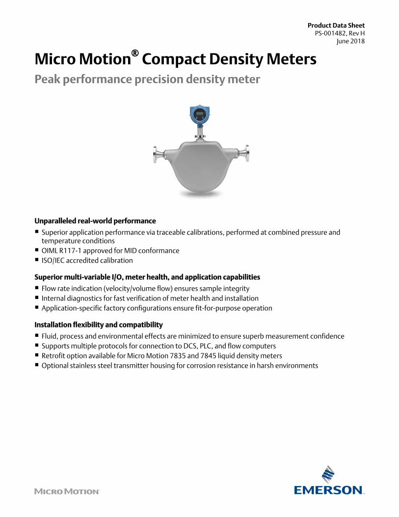
Application configurationsYou can preselect an application-specific configuration for your meter from a wide range of options.
DensityReferred DensitySpecific GravityFlow rate indication (velocity)°API%Concentration%Alcohol by Volume (ABV)°Brix, °Baume, °Plato
Integral transmitterSupports Time Period Signal (TPS), 2-wire TPS, Analog (4–20 mA), HART, WirelessHART®, and Modbus RS-485 communications.
STATUS
SCROLL
SELECT
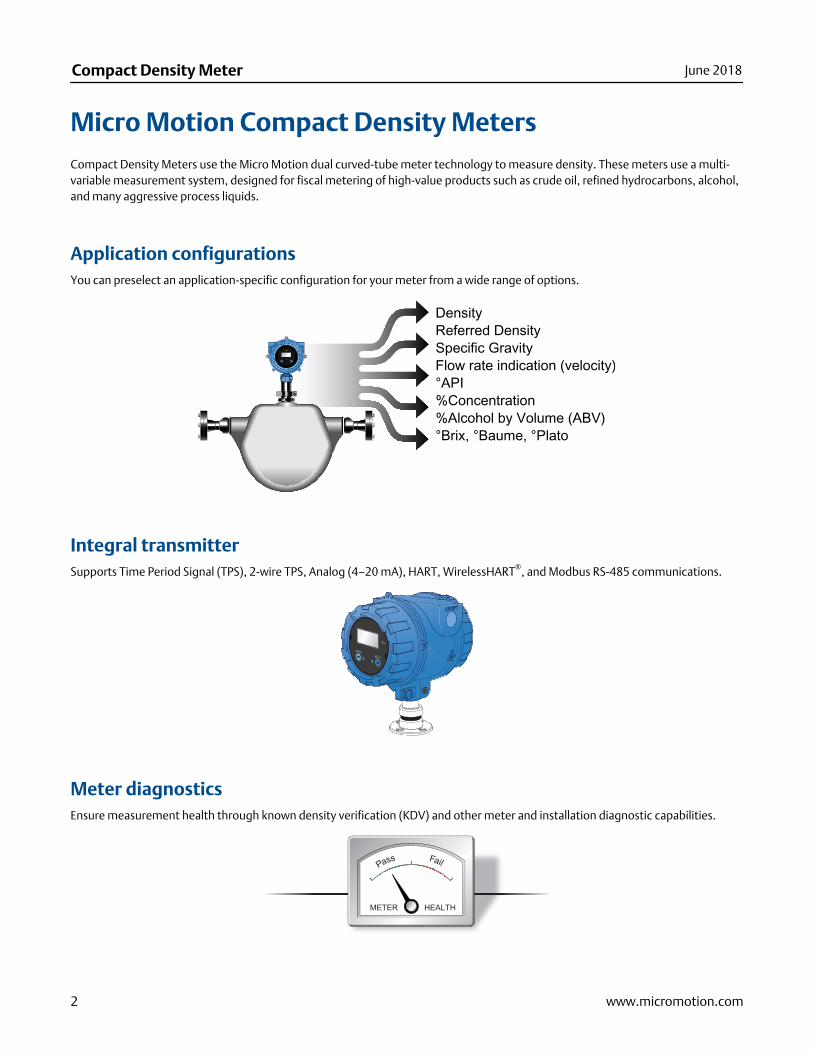
Meter diagnosticsEnsure measurement health through known density verification (KDV) and other meter and installation diagnostic capabilities.
Compact Density Meter June 2018
2 www.micromotion.com
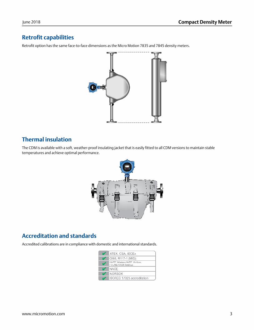
Retrofit capabilitiesRetrofit option has the same face-to-face dimensions as the Micro Motion 7835 and 7845 density meters.
Thermal insulationThe CDM is available with a soft, weather-proof insulating jacket that is easily fitted to all CDM versions to maintain stabletemperatures and achieve optimal performance.
Accreditation and standardsAccredited calibrations are in compliance with domestic and international standards.
June 2018 Compact Density Meter
www.micromotion.com 3
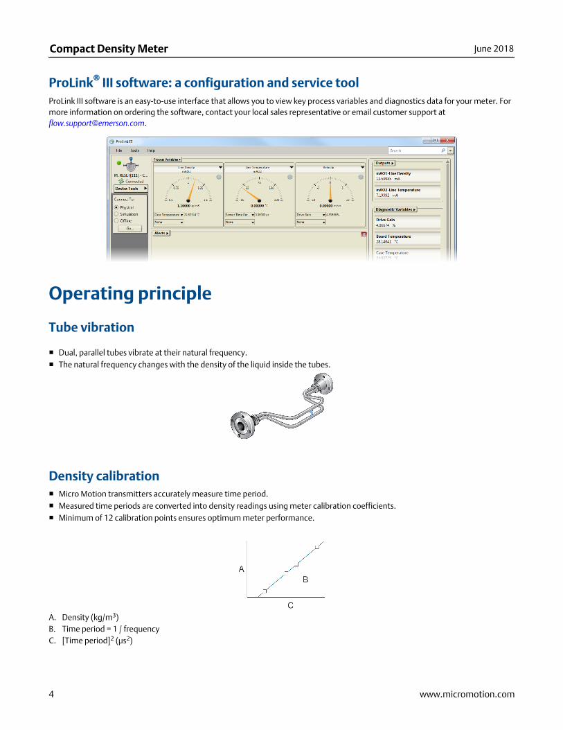
ProLink® III software: a configuration and service toolProLink III software is an easy-to-use interface that allows you to view key process variables and diagnostics data for your meter. Formore information on ordering the software, contact your local sales representative or email customer support at [email protected].
Operating principle
Tube vibration
■ Dual, parallel tubes vibrate at their natural frequency.■ The natural frequency changes with the density of the liquid inside the tubes.
Density calibration■ Micro Motion transmitters accurately measure time period.■ Measured time periods are converted into density readings using meter calibration coefficients.■ Minimum of 12 calibration points ensures optimum meter performance.
A. Density (kg/m3)B. Time period = 1 / frequencyC. [Time period]2 (μs2)
Compact Density Meter June 2018
4 www.micromotion.com
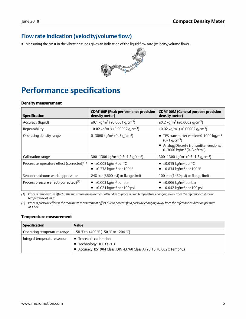
Flow rate indication (velocity/volume flow)■ Measuring the twist in the vibrating tubes gives an indication of the liquid flow rate (velocity/volume flow).
Performance specificationsDensity measurement
SpecificationCDM100P (Peak performance precisiondensity meter)
CDM100M (General purpose precisiondensity meter)
Accuracy (liquid) ±0.1 kg/m3 (±0.0001 g/cm3) ±0.2 kg/m3 (±0.0002 g/cm3)
Repeatability ±0.02 kg/m3 (±0.00002 g/cm3) ±0.02 kg/m3 (±0.00002 g/cm3)
Operating density range 0–3000 kg/m3 (0–3 g/cm3) ■ TPS transmitter version:0-1000 kg/m3
(0–1 g/cm3)■ Analog/Discrete transmitter versions:
0–3000 kg/m3 (0–3 g/cm3)
Calibration range 300–1300 kg/m3 (0.3–1.3 g/cm3) 300–1300 kg/m3 (0.3–1.3 g/cm3)
Process temperature effect (corrected)(1) ■ ±0.005 kg/m3 per °C■ ±0.278 kg/m3 per 100 °F
■ ±0.015 kg/m3 per °C■ ±0.834 kg/m3 per 100 °F
Sensor maximum working pressure 248 bar (3600 psi) or flange limit 100 bar (1450 psi) or flange limit
Process pressure effect (corrected)(2) ■ ±0.003 kg/m3 per bar■ ±0.021 kg/m3 per 100 psi
■ ±0.006 kg/m3 per bar■ ±0.042 kg/m3 per 100 psi
(1) Process temperature effect is the maximum measurement offset due to process fluid temperature changing away from the reference calibrationtemperature of 20 °C.
(2) Process pressure effect is the maximum measurement offset due to process fluid pressure changing away from the reference calibration pressureof 1 bar.
Temperature measurement
Specification Value
Operating temperature range –58 °F to +400 °F (–50 °C to +204 °C)
Integral temperature sensor ■ Traceable calibration■ Technology: 100 Ω RTD■ Accuracy: BS1904 Class, DIN 43760 Class A (±0.15 +0.002 x Temp °C)
June 2018 Compact Density Meter
www.micromotion.com 5

Specification Value
Case temperature sensors(1) ■ Technology: 3 x 100 Ω RTD■ Accuracy: BS1904 Class, DIN 43760 Class B (±0.30 +0.005 x Temp °C)
(1) Case temperature sensors are used for environmental temperature effect correction in applications where the case temperature measurementdoes not need to be traceable and/or accredited. Where accreditation and measurement traceability are required, these sensors are used fordiagnostics purposes only and do not perform any correction on the density measurement.
Case pressure
Specification Value
Maximum case working pres-sure
27 bar (389 psig)
Typical burst pressure (case) 195 bar (2824 psig)
Diagnostic flow rate indication (velocity/volume flow)Expected accuracy is within ±5% of reading.
Typical flow recommendations Flow rate Velocity
Minimum 3 gpm (700 L/hr) 1.5 ft/sec (0.5 m/sec)
Normal 11 gpm (2,500 L/hr) 5 ft/sec (1.5 m/sec)
Maximum 75 gpm (17,000 L/hr) 30 ft/sec (9 m/sec)
NoteFor fluids that contain abrasive particles, velocity should be below 10 ft/s (3 m/s).
Transmitter specifications
Available transmitter versionsFor more information on the transmitter outputs and ordering codes, see the product ordering information.
Analog
Typical application
Output channels
A B C
■ General purpose measurement■ DCS/PLC connection
4–20 mA + HART(passive)
4–20 mA (passive) Modbus/RS-485
Compact Density Meter June 2018
6 www.micromotion.com
Processor for remote-mount Model 2700 FOUNDATION fieldbus transmitter
Typical application
Output channels
A B C
■ General purpose measurement■ DCS/PLC connection
Disabled Disabled Modbus/RS-485
Discrete
Typical application
Output channels
A B C
■ General purpose measurement with outputswitch
■ DCS/PLC connection
4–20 mA + HART(passive)
Discrete output Modbus/RS-485
Time Period Signal (TPS)
Typical application
Output channels
A B C
■ Fiscal/Custody Transfer■ Flow computer connection
4–20 mA + HART(passive)
Time Period Signal(TPS)
Modbus/RS-485
The 4-20 mA output cannot be configured to output line density.
2-wire TPS
Typical application
Output channels
A B C
■ Fiscal/Custody Transfer■ Flow computer connection
Disabled 4-wire 100 Ω, RTD
For the 2-wire transmitter version, TPS is superimposed on power lines.
Local display
Design Features
Physical ■ Segmented two-line LCD screen.■ Can be rotated on transmitter, in 90-degree increments, for ease of viewing.■ Suitable for hazardous area operation.■ Optical switch controls for hazardous area configuration and display.■ Glass lens.■ Three-color LED indicates meter and alert status.
June 2018 Compact Density Meter
www.micromotion.com 7
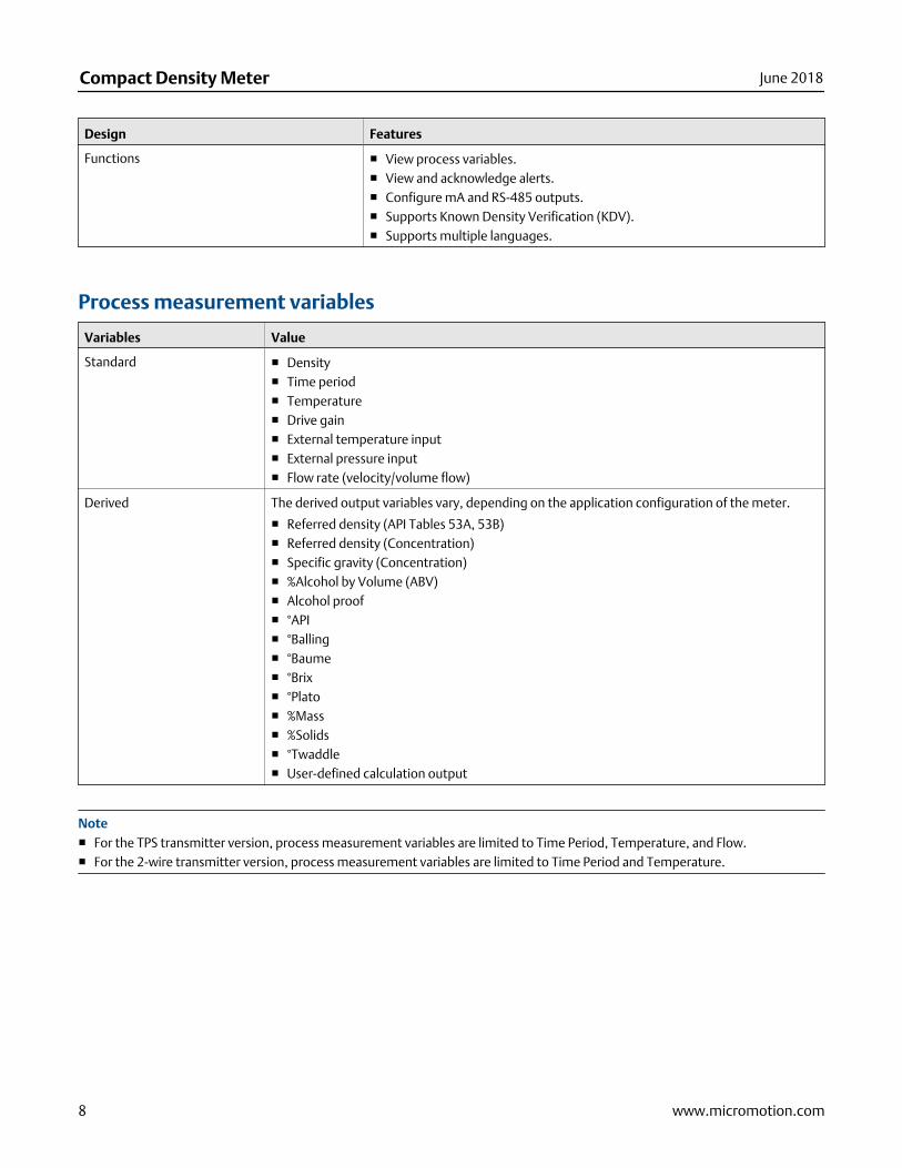
Design Features
Functions ■ View process variables.■ View and acknowledge alerts.■ Configure mA and RS-485 outputs.■ Supports Known Density Verification (KDV).■ Supports multiple languages.
Process measurement variables
Variables Value
Standard ■ Density■ Time period■ Temperature■ Drive gain■ External temperature input■ External pressure input■ Flow rate (velocity/volume flow)
Derived The derived output variables vary, depending on the application configuration of the meter.
■ Referred density (API Tables 53A, 53B)■ Referred density (Concentration)■ Specific gravity (Concentration)■ %Alcohol by Volume (ABV)■ Alcohol proof■ °API■ °Balling■ °Baume■ °Brix■ °Plato■ %Mass■ %Solids■ °Twaddle■ User-defined calculation output
Note■ For the TPS transmitter version, process measurement variables are limited to Time Period, Temperature, and Flow.■ For the 2-wire transmitter version, process measurement variables are limited to Time Period and Temperature.
Compact Density Meter June 2018
8 www.micromotion.com
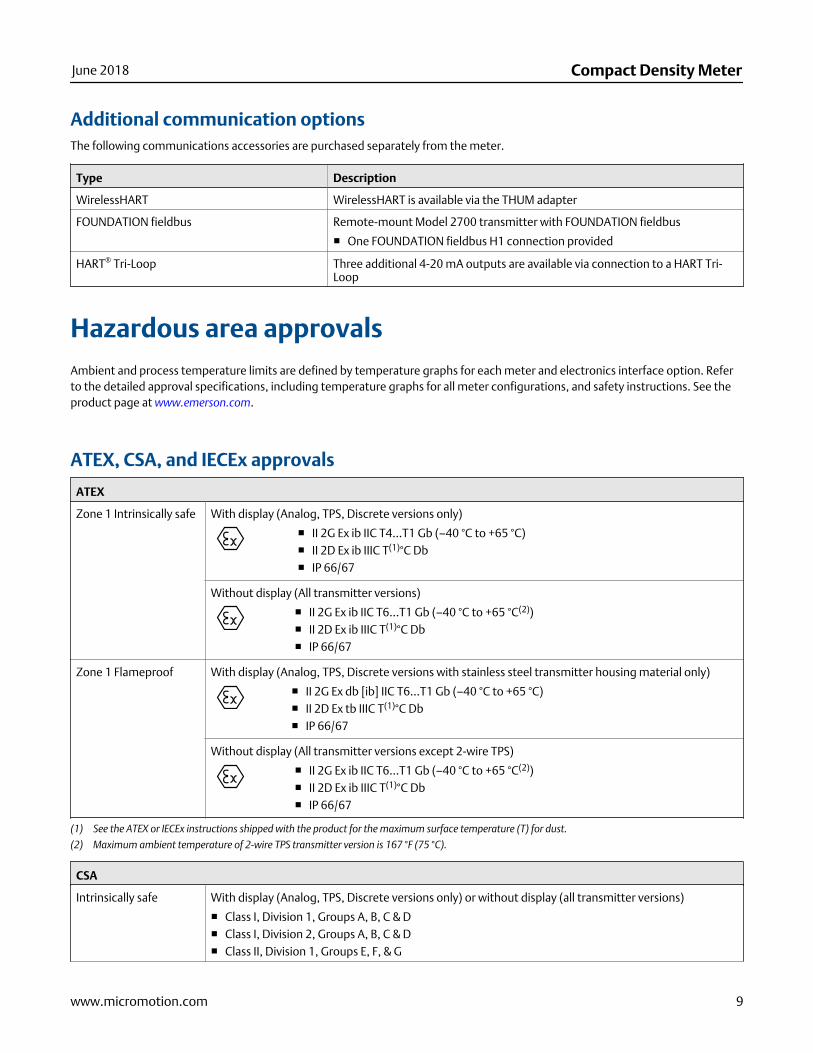
Additional communication optionsThe following communications accessories are purchased separately from the meter.
Type Description
WirelessHART WirelessHART is available via the THUM adapter
FOUNDATION fieldbus Remote-mount Model 2700 transmitter with FOUNDATION fieldbus
■ One FOUNDATION fieldbus H1 connection provided
HART® Tri-Loop Three additional 4-20 mA outputs are available via connection to a HART Tri-Loop
Hazardous area approvalsAmbient and process temperature limits are defined by temperature graphs for each meter and electronics interface option. Referto the detailed approval specifications, including temperature graphs for all meter configurations, and safety instructions. See theproduct page at www.emerson.com.
ATEX, CSA, and IECEx approvals
ATEX
Zone 1 Intrinsically safe With display (Analog, TPS, Discrete versions only)
■ II 2G Ex ib IIC T4...T1 Gb (–40 °C to +65 °C)■ II 2D Ex ib IIIC T(1)°C Db■ IP 66/67
Without display (All transmitter versions)
■ II 2G Ex ib IIC T6...T1 Gb (–40 °C to +65 °C(2))■ II 2D Ex ib IIIC T(1)°C Db■ IP 66/67
Zone 1 Flameproof With display (Analog, TPS, Discrete versions with stainless steel transmitter housing material only)
■ II 2G Ex db [ib] IIC T6...T1 Gb (–40 °C to +65 °C)■ II 2D Ex tb IIIC T(1)°C Db■ IP 66/67
Without display (All transmitter versions except 2-wire TPS)
■ II 2G Ex ib IIC T6...T1 Gb (–40 °C to +65 °C(2))■ II 2D Ex ib IIIC T(1)°C Db■ IP 66/67
(1) See the ATEX or IECEx instructions shipped with the product for the maximum surface temperature (T) for dust.
(2) Maximum ambient temperature of 2-wire TPS transmitter version is 167 °F (75 °C).
CSA
Intrinsically safe With display (Analog, TPS, Discrete versions only) or without display (all transmitter versions)
■ Class I, Division 1, Groups A, B, C & D■ Class I, Division 2, Groups A, B, C & D■ Class II, Division 1, Groups E, F, & G
June 2018 Compact Density Meter
www.micromotion.com 9
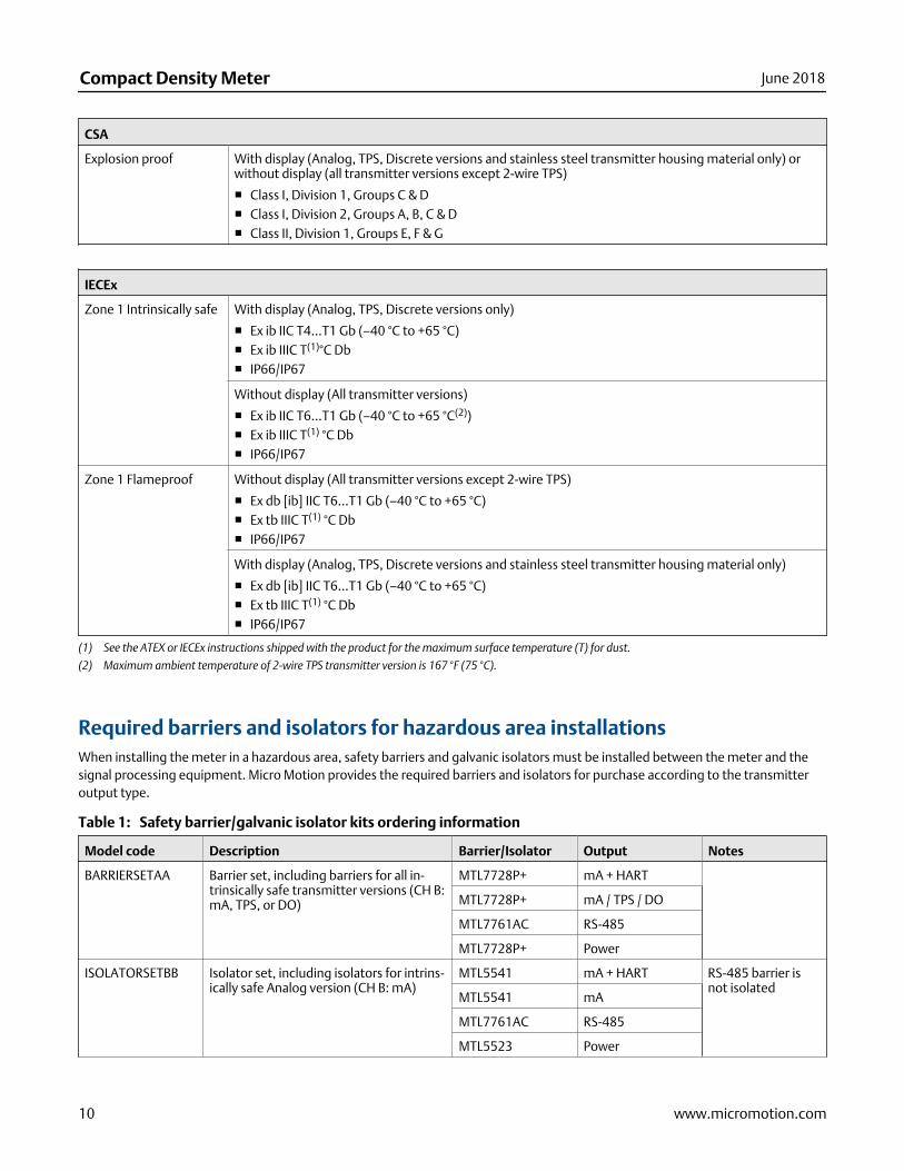
CSA
Explosion proof With display (Analog, TPS, Discrete versions and stainless steel transmitter housing material only) orwithout display (all transmitter versions except 2-wire TPS)
■ Class I, Division 1, Groups C & D■ Class I, Division 2, Groups A, B, C & D■ Class II, Division 1, Groups E, F & G
IECEx
Zone 1 Intrinsically safe With display (Analog, TPS, Discrete versions only)
■ Ex ib IIC T4...T1 Gb (–40 °C to +65 °C)■ Ex ib IIIC T(1)°C Db■ IP66/IP67
Without display (All transmitter versions)
■ Ex ib IIC T6...T1 Gb (–40 °C to +65 °C(2))■ Ex ib IIIC T(1) °C Db■ IP66/IP67
Zone 1 Flameproof Without display (All transmitter versions except 2-wire TPS)
■ Ex db [ib] IIC T6...T1 Gb (–40 °C to +65 °C)■ Ex tb IIIC T(1) °C Db■ IP66/IP67
With display (Analog, TPS, Discrete versions and stainless steel transmitter housing material only)
■ Ex db [ib] IIC T6...T1 Gb (–40 °C to +65 °C)■ Ex tb IIIC T(1) °C Db■ IP66/IP67
(1) See the ATEX or IECEx instructions shipped with the product for the maximum surface temperature (T) for dust.
(2) Maximum ambient temperature of 2-wire TPS transmitter version is 167 °F (75 °C).
Required barriers and isolators for hazardous area installationsWhen installing the meter in a hazardous area, safety barriers and galvanic isolators must be installed between the meter and thesignal processing equipment. Micro Motion provides the required barriers and isolators for purchase according to the transmitteroutput type.
Safety barrier/galvanic isolator kits ordering informationTable 1:
Model code Description Barrier/Isolator Output Notes
BARRIERSETAA Barrier set, including barriers for all in-trinsically safe transmitter versions (CH B:mA, TPS, or DO)
MTL7728P+ mA + HART
MTL7728P+ mA / TPS / DO
MTL7761AC RS-485
MTL7728P+ Power
ISOLATORSETBB Isolator set, including isolators for intrins-ically safe Analog version (CH B: mA)
MTL5541 mA + HART RS-485 barrier isnot isolated
MTL5541 mA
MTL7761AC RS-485
MTL5523 Power
Compact Density Meter June 2018
10 www.micromotion.com
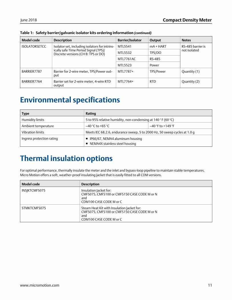
Safety barrier/galvanic isolator kits ordering information (continued)Table 1:
Model code Description Barrier/Isolator Output Notes
ISOLATORSETCC Isolator set, including isolators for intrins-ically safe Time Period Signal (TPS)/Discrete versions (CH B: TPS or DO)
MTL5541 mA + HART RS-485 barrier isnot isolated
MTL5532 TPS/DO
MTL7761AC RS-485
MTL5523 Power
BARRIER7787 Barrier for 2-wire meter, TPS/Power out-put
MTL7787+ TPS/Power Quantity (1)
BARRIER7764 Barrier set for 2-wire meter, 4-wire RTDoutput
MTL7764+ RTD Quantity (2)
Environmental specifications
Type Rating
Humidity limits 5 to 95% relative humidity, non-condensing at 140 ° F (60 °C)
Ambient temperature –40 °C to +65 °C –40 °F to +149 °F
Vibration limits Meets IEC 68.2.6, endurance sweep, 5 to 2000 Hz, 50 sweep cycles at 1.0 g
Ingress protection rating ■ IP66/67, NEMA4 aluminum housing■ NEMA4X stainless steel housing
Thermal insulation optionsFor optimal performance, thermally insulate the meter and the inlet and bypass-loop pipeline to maintain stable temperatures.Micro Motion offers a soft, weather-proof insulating jacket that is easily fitted to all CDM versions.
Model code Description
INSJKTCMFS075 Insulation Jacket for:CMFS075, CMFS100 or CMFS150 CASE CODE M or NandCDM100 CASE CODE M or C
STMKTCMFS075 Steam Heat Kit with Insulation Jacket for:CMFS075, CMFS100 or CMFS150 CASE CODE M or NandCDM100 CASE CODE M or C
June 2018 Compact Density Meter
www.micromotion.com 11
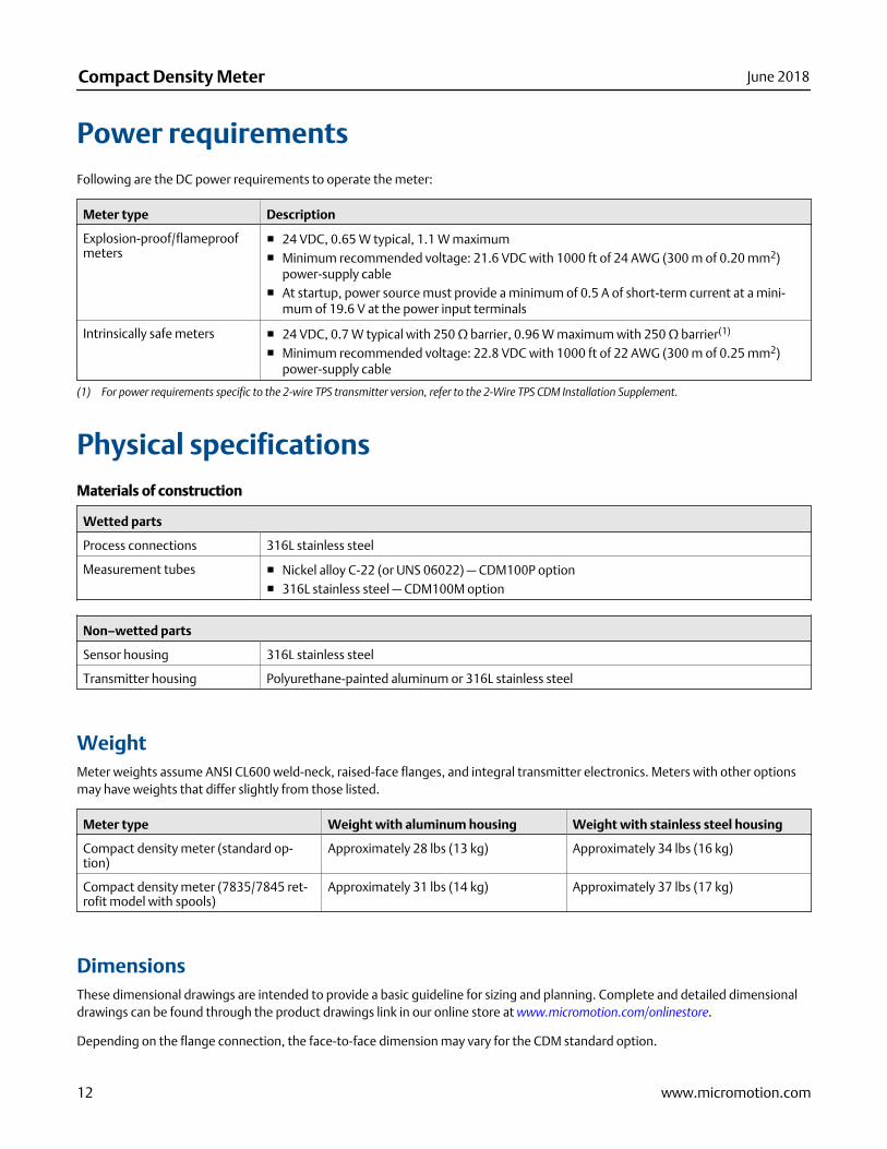
Power requirementsFollowing are the DC power requirements to operate the meter:
Meter type Description
Explosion-proof/flameproofmeters
■ 24 VDC, 0.65 W typical, 1.1 W maximum■ Minimum recommended voltage: 21.6 VDC with 1000 ft of 24 AWG (300 m of 0.20 mm2)
power-supply cable■ At startup, power source must provide a minimum of 0.5 A of short-term current at a mini-
mum of 19.6 V at the power input terminals
Intrinsically safe meters ■ 24 VDC, 0.7 W typical with 250 Ω barrier, 0.96 W maximum with 250 Ω barrier(1)
■ Minimum recommended voltage: 22.8 VDC with 1000 ft of 22 AWG (300 m of 0.25 mm2)power-supply cable
(1) For power requirements specific to the 2-wire TPS transmitter version, refer to the 2-Wire TPS CDM Installation Supplement.
Physical specificationsMaterials of construction
Wetted parts
Process connections 316L stainless steel
Measurement tubes ■ Nickel alloy C-22 (or UNS 06022) — CDM100P option■ 316L stainless steel — CDM100M option
Non–wetted parts
Sensor housing 316L stainless steel
Transmitter housing Polyurethane-painted aluminum or 316L stainless steel
WeightMeter weights assume ANSI CL600 weld-neck, raised-face flanges, and integral transmitter electronics. Meters with other optionsmay have weights that differ slightly from those listed.
Meter type Weight with aluminum housing Weight with stainless steel housing
Compact density meter (standard op-tion)
Approximately 28 lbs (13 kg) Approximately 34 lbs (16 kg)
Compact density meter (7835/7845 ret-rofit model with spools)
Approximately 31 lbs (14 kg) Approximately 37 lbs (17 kg)
DimensionsThese dimensional drawings are intended to provide a basic guideline for sizing and planning. Complete and detailed dimensionaldrawings can be found through the product drawings link in our online store at www.micromotion.com/onlinestore.
Depending on the flange connection, the face-to-face dimension may vary for the CDM standard option.
Compact Density Meter June 2018
12 www.micromotion.com
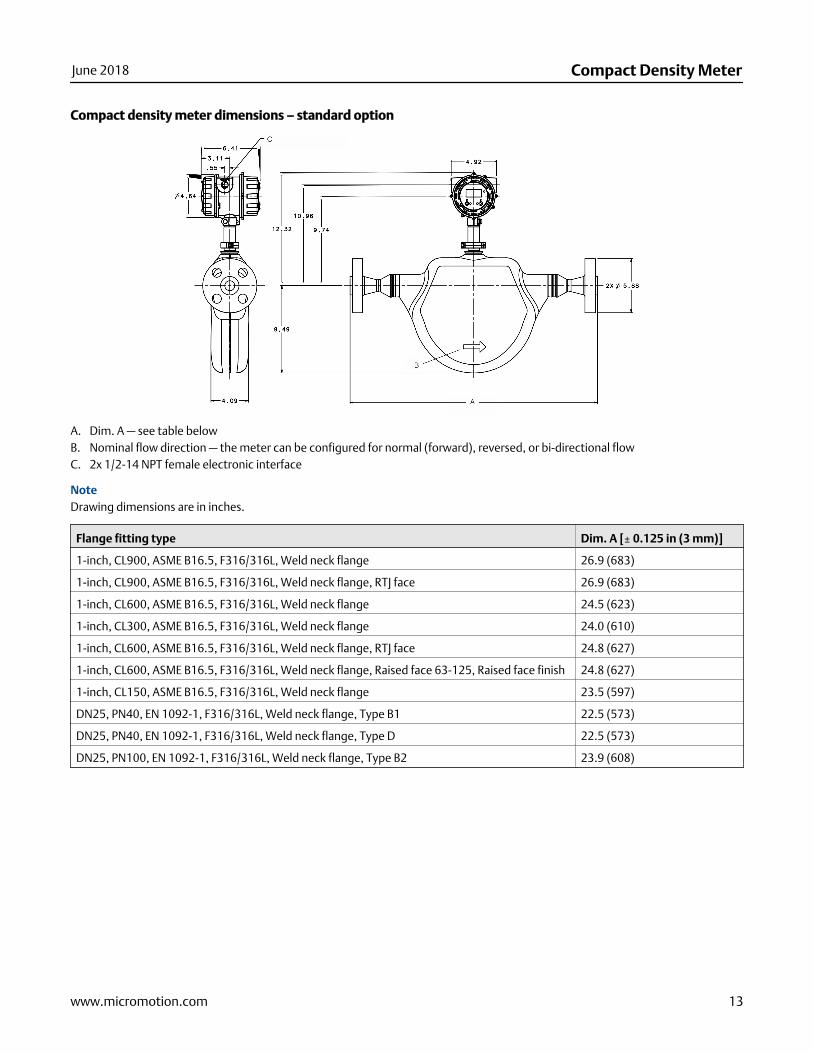
Compact density meter dimensions – standard option
A. Dim. A — see table belowB. Nominal flow direction — the meter can be configured for normal (forward), reversed, or bi-directional flowC. 2x 1/2-14 NPT female electronic interface
NoteDrawing dimensions are in inches.
Flange fitting type Dim. A [± 0.125 in (3 mm)]
1-inch, CL900, ASME B16.5, F316/316L, Weld neck flange 26.9 (683)
1-inch, CL900, ASME B16.5, F316/316L, Weld neck flange, RTJ face 26.9 (683)
1-inch, CL600, ASME B16.5, F316/316L, Weld neck flange 24.5 (623)
1-inch, CL300, ASME B16.5, F316/316L, Weld neck flange 24.0 (610)
1-inch, CL600, ASME B16.5, F316/316L, Weld neck flange, RTJ face 24.8 (627)
1-inch, CL600, ASME B16.5, F316/316L, Weld neck flange, Raised face 63-125, Raised face finish 24.8 (627)
1-inch, CL150, ASME B16.5, F316/316L, Weld neck flange 23.5 (597)
DN25, PN40, EN 1092-1, F316/316L, Weld neck flange, Type B1 22.5 (573)
DN25, PN40, EN 1092-1, F316/316L, Weld neck flange, Type D 22.5 (573)
DN25, PN100, EN 1092-1, F316/316L, Weld neck flange, Type B2 23.9 (608)
June 2018 Compact Density Meter
www.micromotion.com 13
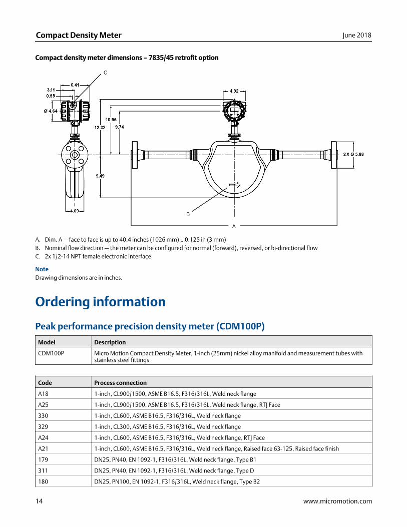
Compact density meter dimensions – 7835/45 retrofit option
A. Dim. A — face to face is up to 40.4 inches (1026 mm) ± 0.125 in (3 mm)B. Nominal flow direction — the meter can be configured for normal (forward), reversed, or bi-directional flowC. 2x 1/2-14 NPT female electronic interface
NoteDrawing dimensions are in inches.
Ordering information
Peak performance precision density meter (CDM100P)
Model Description
CDM100P Micro Motion Compact Density Meter, 1-inch (25mm) nickel alloy manifold and measurement tubes withstainless steel fittings
Code Process connection
A18 1-inch, CL900/1500, ASME B16.5, F316/316L, Weld neck flange
A25 1-inch, CL900/1500, ASME B16.5, F316/316L, Weld neck flange, RTJ Face
330 1-inch, CL600, ASME B16.5, F316/316L, Weld neck flange
329 1-inch, CL300, ASME B16.5, F316/316L, Weld neck flange
A24 1-inch, CL600, ASME B16.5, F316/316L, Weld neck flange, RTJ Face
A21 1-inch, CL600, ASME B16.5, F316/316L, Weld neck flange, Raised face 63-125, Raised face finish
179 DN25, PN40, EN 1092-1, F316/316L, Weld neck flange, Type B1
311 DN25, PN40, EN 1092-1, F316/316L, Weld neck flange, Type D
180 DN25, PN100, EN 1092-1, F316/316L, Weld neck flange, Type B2
Compact Density Meter June 2018
14 www.micromotion.com
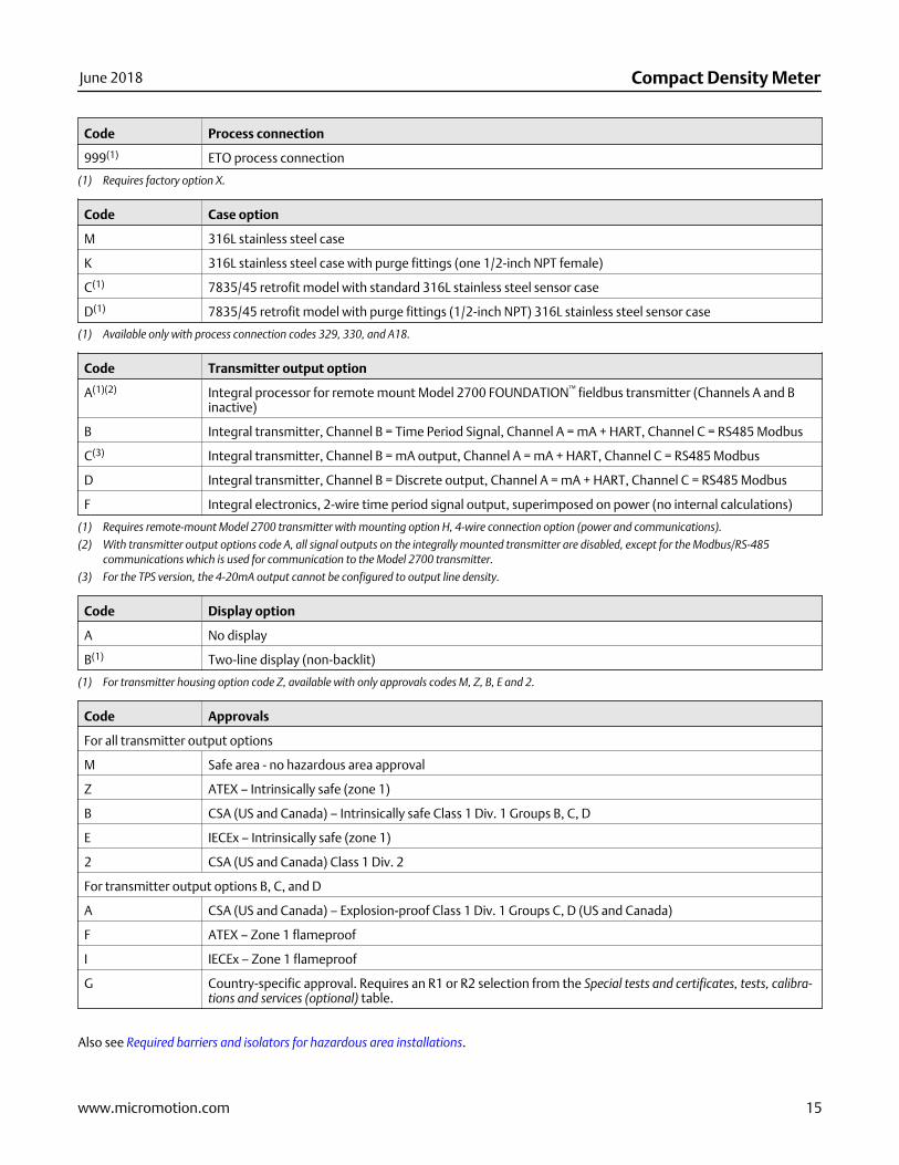
Code Process connection
999(1) ETO process connection
(1) Requires factory option X.
Code Case option
M 316L stainless steel case
K 316L stainless steel case with purge fittings (one 1/2-inch NPT female)
C(1) 7835/45 retrofit model with standard 316L stainless steel sensor case
D(1) 7835/45 retrofit model with purge fittings (1/2-inch NPT) 316L stainless steel sensor case
(1) Available only with process connection codes 329, 330, and A18.
Code Transmitter output option
A(1)(2) Integral processor for remote mount Model 2700 FOUNDATION™ fieldbus transmitter (Channels A and Binactive)
B Integral transmitter, Channel B = Time Period Signal, Channel A = mA + HART, Channel C = RS485 Modbus
C(3) Integral transmitter, Channel B = mA output, Channel A = mA + HART, Channel C = RS485 Modbus
D Integral transmitter, Channel B = Discrete output, Channel A = mA + HART, Channel C = RS485 Modbus
F Integral electronics, 2-wire time period signal output, superimposed on power (no internal calculations)
(1) Requires remote-mount Model 2700 transmitter with mounting option H, 4-wire connection option (power and communications).
(2) With transmitter output options code A, all signal outputs on the integrally mounted transmitter are disabled, except for the Modbus/RS-485communications which is used for communication to the Model 2700 transmitter.
(3) For the TPS version, the 4-20mA output cannot be configured to output line density.
Code Display option
A No display
B(1) Two-line display (non-backlit)
(1) For transmitter housing option code Z, available with only approvals codes M, Z, B, E and 2.
Code Approvals
For all transmitter output options
M Safe area - no hazardous area approval
Z ATEX – Intrinsically safe (zone 1)
B CSA (US and Canada) – Intrinsically safe Class 1 Div. 1 Groups B, C, D
E IECEx – Intrinsically safe (zone 1)
2 CSA (US and Canada) Class 1 Div. 2
For transmitter output options B, C, and D
A CSA (US and Canada) – Explosion-proof Class 1 Div. 1 Groups C, D (US and Canada)
F ATEX – Zone 1 flameproof
I IECEx – Zone 1 flameproof
G Country-specific approval. Requires an R1 or R2 selection from the Special tests and certificates, tests, calibra-tions and services (optional) table.
Also see Required barriers and isolators for hazardous area installations.
June 2018 Compact Density Meter
www.micromotion.com 15
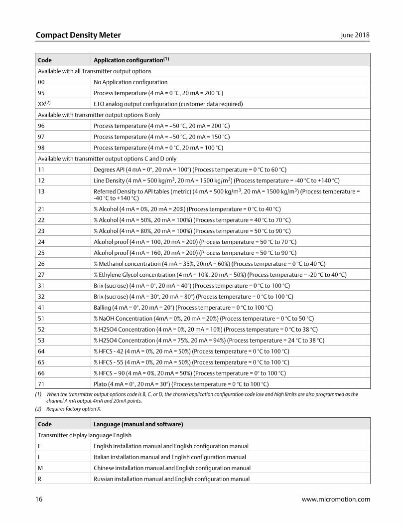
Code Application configuration(1)
Available with all Transmitter output options
00 No Application configuration
95 Process temperature (4 mA = 0 °C, 20 mA = 200 °C)
XX(2) ETO analog output configuration (customer data required)
Available with transmitter output options B only
96 Process temperature (4 mA = –50 °C, 20 mA = 200 °C)
97 Process temperature (4 mA = –50 °C, 20 mA = 150 °C)
98 Process temperature (4 mA = 0 °C, 20 mA = 100 °C)
Available with transmitter output options C and D only
11 Degrees API (4 mA = 0°, 20 mA = 100°) (Process temperature = 0 °C to 60 °C)
12 Line Density (4 mA = 500 kg/m3, 20 mA = 1500 kg/m3) (Process temperature = -40 °C to +140 °C)
13 Referred Density to API tables (metric) (4 mA = 500 kg/m3, 20 mA = 1500 kg/m3) (Process temperature =-40 °C to +140 °C)
21 % Alcohol (4 mA = 0%, 20 mA = 20%) (Process temperature = 0 °C to 40 °C)
22 % Alcohol (4 mA = 50%, 20 mA = 100%) (Process temperature = 40 °C to 70 °C)
23 % Alcohol (4 mA = 80%, 20 mA = 100%) (Process temperature = 50 °C to 90 °C)
24 Alcohol proof (4 mA = 100, 20 mA = 200) (Process temperature = 50 °C to 70 °C)
25 Alcohol proof (4 mA = 160, 20 mA = 200) (Process temperature = 50 °C to 90 °C)
26 % Methanol concentration (4 mA = 35%, 20mA = 60%) (Process temperature = 0 °C to 40 °C)
27 % Ethylene Glycol concentration (4 mA = 10%, 20 mA = 50%) (Process temperature = -20 °C to 40 °C)
31 Brix (sucrose) (4 mA = 0°, 20 mA = 40°) (Process temperature = 0 °C to 100 °C)
32 Brix (sucrose) (4 mA = 30°, 20 mA = 80°) (Process temperature = 0 °C to 100 °C)
41 Balling (4 mA = 0°, 20 mA = 20°) (Process temperature = 0 °C to 100 °C)
51 % NaOH Concentration (4mA = 0%, 20 mA = 20%) (Process temperature = 0 °C to 50 °C)
52 % H2SO4 Concentration (4 mA = 0%, 20 mA = 10%) (Process temperature = 0 °C to 38 °C)
53 % H2SO4 Concentration (4 mA = 75%, 20 mA = 94%) (Process temperature = 24 °C to 38 °C)
64 % HFCS - 42 (4 mA = 0%, 20 mA = 50%) (Process temperature = 0 °C to 100 °C)
65 % HFCS - 55 (4 mA = 0%, 20 mA = 50%) (Process temperature = 0 °C to 100 °C)
66 % HFCS – 90 (4 mA = 0%, 20 mA = 50%) (Process temperature = 0° to 100 °C)
71 Plato (4 mA = 0°, 20 mA = 30°) (Process temperature = 0 °C to 100 °C)
(1) When the transmitter output options code is B, C, or D, the chosen application configuration code low and high limits are also programmed as thechannel A mA output 4mA and 20mA points.
(2) Requires factory option X.
Code Language (manual and software)
Transmitter display language English
E English installation manual and English configuration manual
I Italian installation manual and English configuration manual
M Chinese installation manual and English configuration manual
R Russian installation manual and English configuration manual
Compact Density Meter June 2018
16 www.micromotion.com
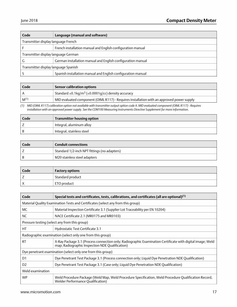
Code Language (manual and software)
Transmitter display language French
F French installation manual and English configuration manual
Transmitter display language German
G German installation manual and English configuration manual
Transmitter display language Spanish
S Spanish installation manual and English configuration manual
Code Sensor calibration options
A Standard ±0.1kg/m3 (±0.0001g/cc) density accuracy
M(1) MID evaluated component (OIML R117) - Requires installation with an approved power supply
(1) MID (OIML R117) calibration option not available with transmitter output option code A. MID evaluated component (OIML R117) - Requiresinstallation with an approved power supply. See the CDM100 Measuring Instruments Directive Supplement for more information.
Code Transmitter housing option
Z Integral, aluminum alloy
B Integral, stainless steel
Code Conduit connections
Z Standard 1/2-inch NPT fittings (no adapters)
B M20 stainless steel adapters
Code Factory options
Z Standard product
X ETO product
Code Special tests and certificates, tests, calibrations, and certificates (all are optional)(1)
Material Quality Examination Tests and Certificates (select any from this group)
MC Material Inspection Certificate 3.1 (Supplier Lot Traceability per EN 10204)
NC NACE Certificate 2.1 (MR0175 and MR0103)
Pressure testing (select any from this group)
HT Hydrostatic Test Certificate 3.1
Radiographic examination (select only one from this group)
RT X-Ray Package 3.1 (Process connection only; Radiographic Examination Certificate with digital image; Weldmap; Radiographic Inspection NDE Qualification)
Dye penetrant examination (select only one from this group)
D1 Dye Penetrant Test Package 3.1 (Process connection only; Liquid Dye Penetration NDE Qualification)
D2 Dye Penetrant Test Package 3.1 (Case only; Liquid Dye Penetration NDE Qualification)
Weld examination
WP Weld Procedure Package (Weld Map, Weld Procedure Specification, Weld Procedure Qualification Record,Welder Performance Qualification)
June 2018 Compact Density Meter
www.micromotion.com 17

Code Special tests and certificates, tests, calibrations, and certificates (all are optional)(1)
Positive material testing (select only one from this group)
PM Positive Material Test Certificate 3.1 (without carbon content)
Sensor completion options (select any from this group)
WG Witness General
SP Special Packaging
Instrument tagging
TG Instrument Tagging – customer information required (max. 24 characters)
Country-specific approvals (select only one when Approvals option G is selected)
R1(2) (3) EAC Zone 1 - Hazardous area approval - intrinsically safe
R2(2) (3) EAC Zone 1 - Hazardous area approval - flameproof terminal compartment
(1) Multiple test or certificate options can be selected.
(2) Available only with approval G
(3) Not available with Transmitter Output Options code F or Transmitter Housing Option B
General purpose precision density meter (CDM100M)
Model Description
CDM100M Micro Motion Compact Density Meter, 1-inch (25 mm), 316L stainless steel manifold and measurementtubes
Code Process connection
330 1-inch, CL600, ASME B16.5, F316/316L, Weld neck flange
329 1-inch, CL300, ASME B16.5, F316/316L, Weld neck flange
A24 1-inch, CL600, ASME B16.5, F316/316L, Weld neck flange, RTJ Face
A21 1-inch, CL600, ASME B16.5, F316/316L, Weld neck flange, Raised face 63-125, Raised face finish
179 DN25, PN40, EN 1092-1, F316/316L, Weld neck flange, Type B1
311 DN25, PN40, EN 1092-1, F316/316L, Weld neck flange, Type D
180 DN25, PN100, EN 1092-1, F316/316L, Weld neck flange, Type B2
328 1-inch, CL150, ASME B16.5, F316/316L, Weld neck flange
999(1) ETO process connection
(1) Requires factory option X.
Code Case options
M 316L stainless steel case
K 316L stainless steel case with purge fittings (one 1/2-inch NPT female)
C(1) 7845 retrofit model with standard 316L stainless steel sensor case
Compact Density Meter June 2018
18 www.micromotion.com
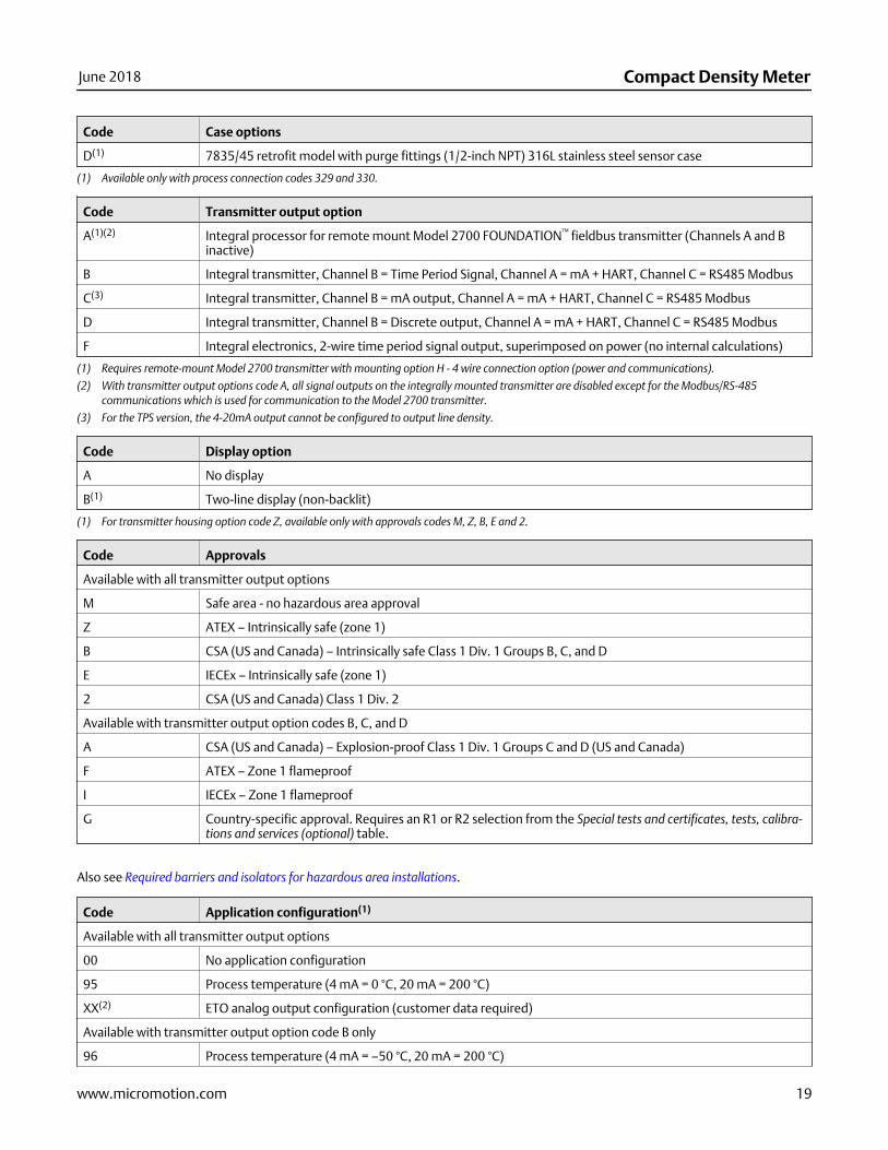
Code Case options
D(1) 7835/45 retrofit model with purge fittings (1/2-inch NPT) 316L stainless steel sensor case
(1) Available only with process connection codes 329 and 330.
Code Transmitter output option
A(1)(2) Integral processor for remote mount Model 2700 FOUNDATION™ fieldbus transmitter (Channels A and Binactive)
B Integral transmitter, Channel B = Time Period Signal, Channel A = mA + HART, Channel C = RS485 Modbus
C(3) Integral transmitter, Channel B = mA output, Channel A = mA + HART, Channel C = RS485 Modbus
D Integral transmitter, Channel B = Discrete output, Channel A = mA + HART, Channel C = RS485 Modbus
F Integral electronics, 2-wire time period signal output, superimposed on power (no internal calculations)
(1) Requires remote-mount Model 2700 transmitter with mounting option H - 4 wire connection option (power and communications).
(2) With transmitter output options code A, all signal outputs on the integrally mounted transmitter are disabled except for the Modbus/RS-485communications which is used for communication to the Model 2700 transmitter.
(3) For the TPS version, the 4-20mA output cannot be configured to output line density.
Code Display option
A No display
B(1) Two-line display (non-backlit)
(1) For transmitter housing option code Z, available only with approvals codes M, Z, B, E and 2.
Code Approvals
Available with all transmitter output options
M Safe area - no hazardous area approval
Z ATEX – Intrinsically safe (zone 1)
B CSA (US and Canada) – Intrinsically safe Class 1 Div. 1 Groups B, C, and D
E IECEx – Intrinsically safe (zone 1)
2 CSA (US and Canada) Class 1 Div. 2
Available with transmitter output option codes B, C, and D
A CSA (US and Canada) – Explosion-proof Class 1 Div. 1 Groups C and D (US and Canada)
F ATEX – Zone 1 flameproof
I IECEx – Zone 1 flameproof
G Country-specific approval. Requires an R1 or R2 selection from the Special tests and certificates, tests, calibra-tions and services (optional) table.
Also see Required barriers and isolators for hazardous area installations.
Code Application configuration(1)
Available with all transmitter output options
00 No application configuration
95 Process temperature (4 mA = 0 °C, 20 mA = 200 °C)
XX(2) ETO analog output configuration (customer data required)
Available with transmitter output option code B only
96 Process temperature (4 mA = –50 °C, 20 mA = 200 °C)
June 2018 Compact Density Meter
www.micromotion.com 19
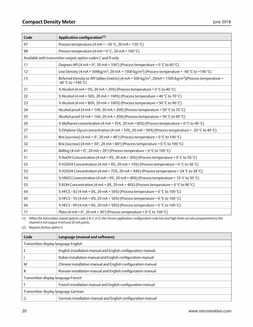
Code Application configuration(1)
97 Process temperature (4 mA = –50 °C, 20 mA = 150 °C)
98 Process temperature (4 mA = 0 °C, 20 mA = 100 °C)
Available with transmitter output option codes C and D only
11 Degrees API (4 mA = 0°, 20 mA = 100°) (Process temperature = 0 °C to 60 °C)
12 Line Density (4 mA = 500kg/m3, 20 mA = 1500 kg/m3) (Process temperature = -40 °C to +140 °C)
13 Referred Density to API tables (metric) (4 mA = 500 kg/m3, 20mA = 1500 kg/m3)(Process temperature =-40 °C to +140 °C)
21 % Alcohol (4 mA = 0%, 20 mA = 20%) (Process temperature = 0 °C to 40 °C)
22 % Alcohol (4 mA = 50%, 20 mA = 100%) (Process temperature = 40 °C to 70 °C)
23 % Alcohol (4 mA = 80%, 20 mA = 100%) (Process temperature = 50 °C to 90 °C)
24 Alcohol proof (4 mA = 100, 20 mA = 200) (Process temperature = 50 °C to 70 °C)
25 Alcohol proof (4 mA = 160, 20 mA = 200) (Process temperature = 50 °C to 90 °C)
26 % Methanol concentration (4 mA = 35%, 20 mA = 60%) (Process temperature = 0 °C to 40 °C)
27 % Ethylene Glycol concentration (4 mA = 10%, 20 mA = 50%) (Process temperature = -20 °C to 40 °C)
31 Brix (sucrose) (4 mA = 0°, 20 mA = 40°) (Process temperature = 0 °C to 100 °C)
32 Brix (sucrose) (4 mA = 30°, 20 mA = 80°) (Process temperature = 0 °C to 100 °C)
41 Balling (4 mA = 0°, 20 mA = 20°) (Process temperature = 0 °C to 100 °C)
51 % NaOH Concentration (4 mA = 0%, 20 mA = 20%) (Process temperature = 0 °C to 50 °C)
52 % H2SO4 Concentration (4 mA = 0%, 20 mA = 10%) (Process temperature = 0 °C to 38 °C)
53 % H2SO4 Concentration (4 mA = 75%, 20 mA = 94%) (Process temperature = 24 °C to 38 °C)
54 % HNO3 Concentration (4 mA = 0%, 20 mA = 40%) (Process temperature = 10 °C to 50 °C)
55 % KOH Concentration (4 mA = 0%, 20 mA = 40%) (Process temperature = 0 °C to 90 °C)
64 % HFCS - 42 (4 mA = 0%, 20 mA = 50%) (Process temperature = 0 °C to 100 °C)
65 % HFCS - 55 (4 mA = 0%, 20 mA = 50%) (Process temperature = 0 °C to 100 °C)
66 % HFCS - 90 (4 mA = 0%, 20 mA = 50%) (Process temperature = 0 °C to 100 °C)
71 Plato (4 mA = 0°, 20 mA = 30°) (Process temperature = 0 °C to 100 °C)
(1) When the transmitter output options code is B, C or D, the chosen application configuration code low and high limits are also programmed as thechannel A mA output 4 mA and 20 mA points.
(2) Requires factory option X.
Code Language (manual and software)
Transmitter display language English
E English installation manual and English configuration manual
I Italian installation manual and English configuration manual
M Chinese installation manual and English configuration manual
R Russian installation manual and English configuration manual
Transmitter display language French
F French installation manual and English configuration manual
Transmitter display language German
G German installation manual and English configuration manual
Compact Density Meter June 2018
20 www.micromotion.com
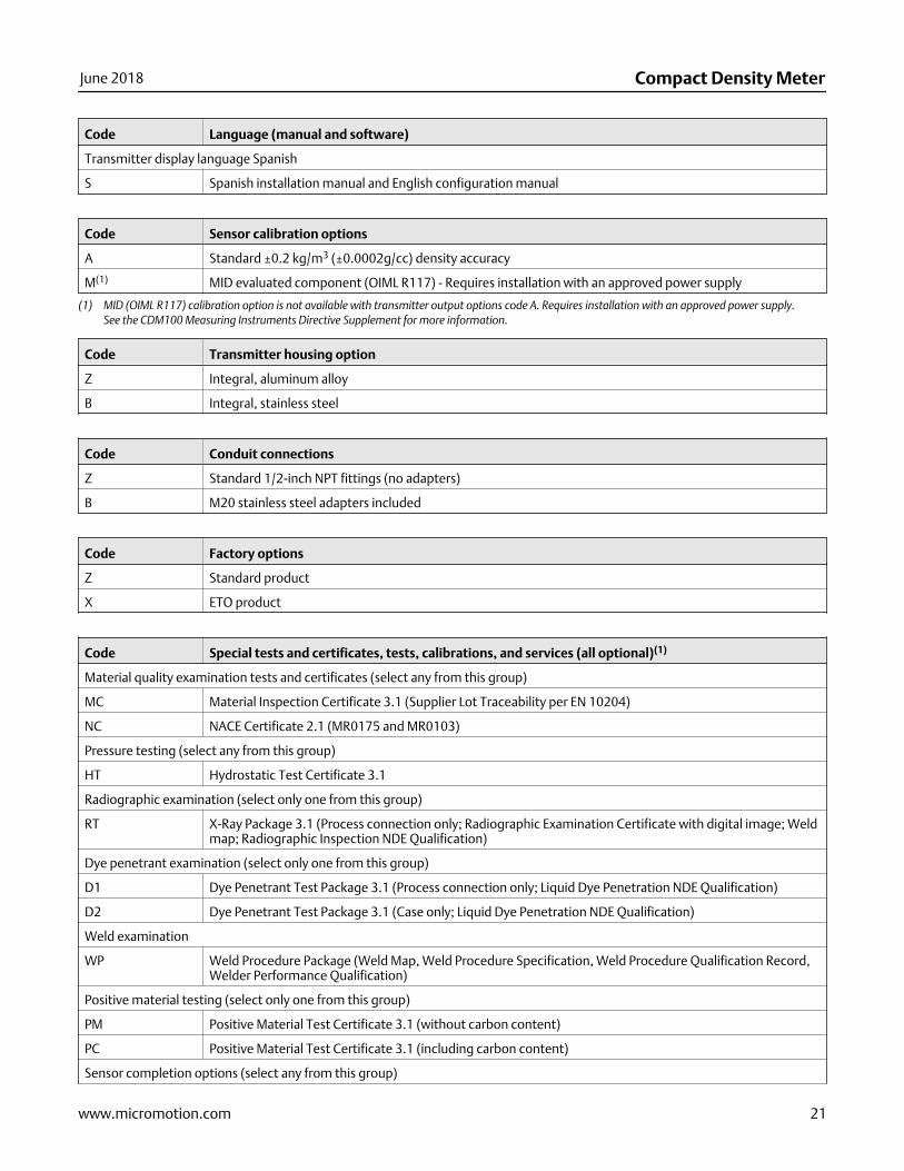
Code Language (manual and software)
Transmitter display language Spanish
S Spanish installation manual and English configuration manual
Code Sensor calibration options
A Standard ±0.2 kg/m3 (±0.0002g/cc) density accuracy
M(1) MID evaluated component (OIML R117) - Requires installation with an approved power supply
(1) MID (OIML R117) calibration option is not available with transmitter output options code A. Requires installation with an approved power supply.See the CDM100 Measuring Instruments Directive Supplement for more information.
Code Transmitter housing option
Z Integral, aluminum alloy
B Integral, stainless steel
Code Conduit connections
Z Standard 1/2-inch NPT fittings (no adapters)
B M20 stainless steel adapters included
Code Factory options
Z Standard product
X ETO product
Code Special tests and certificates, tests, calibrations, and services (all optional)(1)
Material quality examination tests and certificates (select any from this group)
MC Material Inspection Certificate 3.1 (Supplier Lot Traceability per EN 10204)
NC NACE Certificate 2.1 (MR0175 and MR0103)
Pressure testing (select any from this group)
HT Hydrostatic Test Certificate 3.1
Radiographic examination (select only one from this group)
RT X-Ray Package 3.1 (Process connection only; Radiographic Examination Certificate with digital image; Weldmap; Radiographic Inspection NDE Qualification)
Dye penetrant examination (select only one from this group)
D1 Dye Penetrant Test Package 3.1 (Process connection only; Liquid Dye Penetration NDE Qualification)
D2 Dye Penetrant Test Package 3.1 (Case only; Liquid Dye Penetration NDE Qualification)
Weld examination
WP Weld Procedure Package (Weld Map, Weld Procedure Specification, Weld Procedure Qualification Record,Welder Performance Qualification)
Positive material testing (select only one from this group)
PM Positive Material Test Certificate 3.1 (without carbon content)
PC Positive Material Test Certificate 3.1 (including carbon content)
Sensor completion options (select any from this group)
June 2018 Compact Density Meter
www.micromotion.com 21
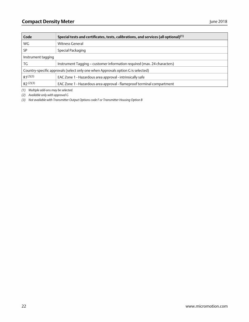
Code Special tests and certificates, tests, calibrations, and services (all optional)(1)
WG Witness General
SP Special Packaging
Instrument tagging
TG Instrument Tagging – customer information required (max. 24 characters)
Country-specific approvals (select only one when Approvals option G is selected)
R1(2)(3) EAC Zone 1 - Hazardous area approval - intrinsically safe
R2 (2)(3) EAC Zone 1 - Hazardous area approval - flameproof terminal compartment
(1) Multiple add-ons may be selected.
(2) Available only with approval G
(3) Not available with Transmitter Output Options code F or Transmitter Housing Option B
Compact Density Meter June 2018
22 www.micromotion.com

June 2018 Compact Density Meter
www.micromotion.com 23
Compact Density MeterPS-001482, Rev H
Product Data SheetJune 2018
Emerson Automation SolutionsWorldwide Headquarters7070 Winchester CircleBoulder, Colorado USA 80301T: +1 800-522-6277T: +1 303-527-5200F: +1 303-530-8459Mexico: 52 55 5809 5300Argentina: 54 11 4837 7000Brazil: 55 15 3413 8147Chile: 56 2 2928 4800
Emerson Automation SolutionsCentral Europe: +41 41 7686 111Eastern Europe: +41 41 7686 111Dubai: +971 4 811 8100Abu Dhabi: +971 2 697 2000France: 0800 917 901Germany: +49 (0) 2173 3348 0Italy: 8008 77334The Netherlands: +31 (0) 70 413 6666Belgium: +32 2 716 77 11Spain: +34 913 586 000U.K.: 0870 240 1978Russian/CIS: +7 495 981 9811
Emerson Automation SolutionsAustralia: (61) 3 9721 0200China: (86) 21 2892 9000India: (91) 22 6662 0566Japan: (81) 3 5769 6803South Korea: (82) 31 8034 0000Singapore: (65) 6 363 7766
©2018 Micro Motion, Inc. All rights reserved.
The Emerson logo is a trademark and service mark of Emerson Electric Co. Micro Motion, ELITE,ProLink, MVD and MVD Direct Connect marks are marks of one of the Emerson AutomationSolutions family of companies. All other marks are property of their respective owners.