Embed Size (px)
Citation preview
Revision 1.0 1 February 2017
Australasian
Health Facility Guidelines
Isolation Rooms – Engineering and Design Requirements
Isolation Rooms, Revision 1.0, 1 February 2017 Page 1
Index
01 INTRODUCTION ................................................................................................................... 2
02 TYPES OF ISOLATION ROOMS .......................................................................................... 2
03 DESIGN FEATURES ............................................................................................................ 3
3.1 Overview ....................................................................................................................... 3
3.2 Pressure Gradient ......................................................................................................... 3
3.3 Principles of System Configuration ................................................................................ 4
3.4 Supply Air and Exhaust System Design ........................................................................ 4
3.5 Air Distribution ............................................................................................................... 4
3.6 Air Change Rates .......................................................................................................... 5
3.7 Monitoring of Room Pressure ........................................................................................ 5
3.8 Quarantine Isolation Rooms .......................................................................................... 6
3.9 Minimum Fresh Air Requirements ................................................................................. 6
3.10 Minimising of Room Air Leaks – Class N and Q Isolation Rooms .................................. 6
3.11 Energy Conservation ..................................................................................................... 8
3.12 Plant Back-up System ................................................................................................... 8
04 USE OF CLASS N ISOLATION ROOMS FOR OTHER PATIENTS ..................................... 9
05 COMMISSIONING AND ONGOING MAINTENANCE......................................................... 10
5.1 Initial Setup Test ......................................................................................................... 10
5.2 Air Quantities ............................................................................................................... 10
5.3 Pressure differentials ................................................................................................... 10
5.3.1 Air Flow Direction between Compartments ...................................................... 10
5.4 Air Distribution ............................................................................................................. 10
5.5 Containment ................................................................................................................ 11
5.6 Room Leakage ............................................................................................................ 11
5.7 HEPA Filter Commissioning ........................................................................................ 11
5.8 Controls ....................................................................................................................... 11
5.9 Thermal Comfort ......................................................................................................... 12
5.10 Records ....................................................................................................................... 12
5.11 Annual Performance Monitoring and Validation ........................................................... 12
06 REFERENCES ................................................................................................................... 13
Australasian Health Facility Guidelines
Isolation Rooms, Revision 1.0, 1 February 2017 Page 2
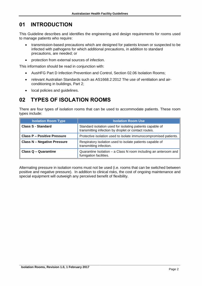
01 INTRODUCTION
This Guideline describes and identifies the engineering and design requirements for rooms used to manage patients who require:
transmission-based precautions which are designed for patients known or suspected to be infected with pathogens for which additional precautions, in addition to standard precautions, are needed; or
protection from external sources of infection.
This information should be read in conjunction with:
AusHFG Part D Infection Prevention and Control, Section 02.06 Isolation Rooms;
relevant Australian Standards such as AS1668.2:2012 The use of ventilation and air-conditioning in buildings, Part 2;
local policies and guidelines.
02 TYPES OF ISOLATION ROOMS
There are four types of isolation rooms that can be used to accommodate patients. These room types include:
Isolation Room Type Isolation Room Use
Class S - Standard Standard isolation used for isolating patients capable of transmitting infection by droplet or contact routes.
Class P – Positive Pressure Protective isolation used to isolate immunocompromised patients.
Class N – Negative Pressure Respiratory isolation used to isolate patients capable of transmitting infection.
Class Q – Quarantine Quarantine Isolation – a Class N room including an anteroom and fumigation facilities.
Alternating pressure in isolation rooms must not be used (i.e. rooms that can be switched between positive and negative pressure). In addition to clinical risks, the cost of ongoing maintenance and special equipment will outweigh any perceived benefit of flexibility.
Australasian Health Facility Guidelines
Isolation Rooms, Revision 1.0, 1 February 2017 Page 3
03 DESIGN FEATURES
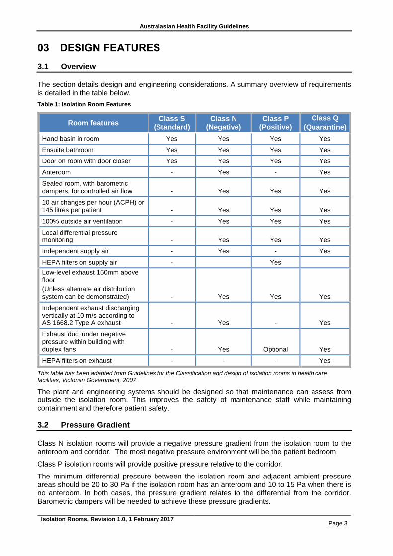
3.1 Overview
The section details design and engineering considerations. A summary overview of requirements is detailed in the table below.
Table 1: Isolation Room Features
Room features Class S
(Standard) Class N
(Negative) Class P
(Positive)
Class Q
(Quarantine)
Hand basin in room Yes Yes Yes Yes
Ensuite bathroom Yes Yes Yes Yes
Door on room with door closer Yes Yes Yes Yes
Anteroom - Yes - Yes
Sealed room, with barometric dampers, for controlled air flow - Yes Yes Yes
10 air changes per hour (ACPH) or 145 litres per patient - Yes Yes Yes
100% outside air ventilation - Yes Yes Yes
Local differential pressure monitoring - Yes Yes Yes
Independent supply air - Yes - Yes
HEPA filters on supply air - Yes
Low-level exhaust 150mm above floor
(Unless alternate air distribution system can be demonstrated) - Yes Yes Yes
Independent exhaust discharging vertically at 10 m/s according to AS 1668.2 Type A exhaust - Yes - Yes
Exhaust duct under negative pressure within building with duplex fans - Yes Optional Yes
HEPA filters on exhaust - - - Yes
This table has been adapted from Guidelines for the Classification and design of isolation rooms in health care facilities, Victorian Government, 2007
The plant and engineering systems should be designed so that maintenance can assess from outside the isolation room. This improves the safety of maintenance staff while maintaining containment and therefore patient safety.
3.2 Pressure Gradient
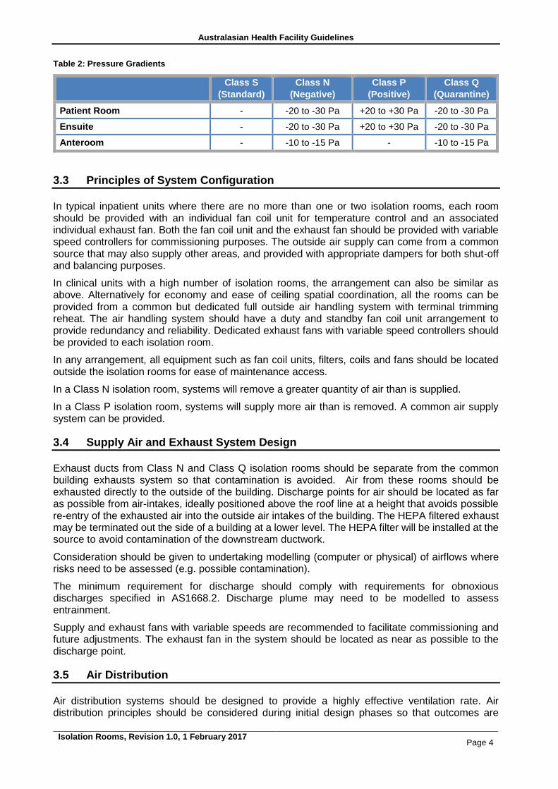
Class N isolation rooms will provide a negative pressure gradient from the isolation room to the anteroom and corridor. The most negative pressure environment will be the patient bedroom
Class P isolation rooms will provide positive pressure relative to the corridor.
The minimum differential pressure between the isolation room and adjacent ambient pressure areas should be 20 to 30 Pa if the isolation room has an anteroom and 10 to 15 Pa when there is no anteroom. In both cases, the pressure gradient relates to the differential from the corridor. Barometric dampers will be needed to achieve these pressure gradients.
Australasian Health Facility Guidelines
Isolation Rooms, Revision 1.0, 1 February 2017 Page 4
Table 2: Pressure Gradients
Class S
(Standard)
Class N
(Negative)
Class P
(Positive)
Class Q
(Quarantine)
Patient Room - -20 to -30 Pa +20 to +30 Pa -20 to -30 Pa
Ensuite - -20 to -30 Pa +20 to +30 Pa -20 to -30 Pa
Anteroom - -10 to -15 Pa - -10 to -15 Pa
3.3 Principles of System Configuration
In typical inpatient units where there are no more than one or two isolation rooms, each room should be provided with an individual fan coil unit for temperature control and an associated individual exhaust fan. Both the fan coil unit and the exhaust fan should be provided with variable speed controllers for commissioning purposes. The outside air supply can come from a common source that may also supply other areas, and provided with appropriate dampers for both shut-off and balancing purposes.
In clinical units with a high number of isolation rooms, the arrangement can also be similar as above. Alternatively for economy and ease of ceiling spatial coordination, all the rooms can be provided from a common but dedicated full outside air handling system with terminal trimming reheat. The air handling system should have a duty and standby fan coil unit arrangement to provide redundancy and reliability. Dedicated exhaust fans with variable speed controllers should be provided to each isolation room.
In any arrangement, all equipment such as fan coil units, filters, coils and fans should be located outside the isolation rooms for ease of maintenance access.
In a Class N isolation room, systems will remove a greater quantity of air than is supplied.
In a Class P isolation room, systems will supply more air than is removed. A common air supply system can be provided.
3.4 Supply Air and Exhaust System Design
Exhaust ducts from Class N and Class Q isolation rooms should be separate from the common building exhausts system so that contamination is avoided. Air from these rooms should be exhausted directly to the outside of the building. Discharge points for air should be located as far as possible from air-intakes, ideally positioned above the roof line at a height that avoids possible re-entry of the exhausted air into the outside air intakes of the building. The HEPA filtered exhaust may be terminated out the side of a building at a lower level. The HEPA filter will be installed at the source to avoid contamination of the downstream ductwork.
Consideration should be given to undertaking modelling (computer or physical) of airflows where risks need to be assessed (e.g. possible contamination).
The minimum requirement for discharge should comply with requirements for obnoxious discharges specified in AS1668.2. Discharge plume may need to be modelled to assess entrainment.
Supply and exhaust fans with variable speeds are recommended to facilitate commissioning and future adjustments. The exhaust fan in the system should be located as near as possible to the discharge point.
3.5 Air Distribution
Air distribution systems should be designed to provide a highly effective ventilation rate. Air distribution principles should be considered during initial design phases so that outcomes are
Australasian Health Facility Guidelines
Isolation Rooms, Revision 1.0, 1 February 2017 Page 5
optimised. Air distribution may be affected by the location and types of isolation room and the location and air flow direction from/ to supply and exhaust registers.
The ventilation system should be designed to ensure the air flows from less contaminated areas to more contaminated areas.
Supply air should be provided to the isolation room so that air turbulence is minimised near the patient. The exhaust however should be maximised near the patient to capture contaminated air. The supply of air flows will change depending on the room type. In a Class N isolation room, the flow of air should protect the healthcare worker. That is, the air should flow from the healthcare worker, to the patient and then be removed via the exhaust. In a Class P isolation room, the flow of air should protect the patient. That is, the air should flow from the patient, to the healthcare worker and then be removed via the exhaust.
The location of exhaust air grilles should be place so that air is drawn away from the patient zone. Ensuites will have dedicated exhaust with minimum rates as detailed in AS1668.2.
3.6 Air Change Rates
The total quantity of air supplied into the isolation room should be a minimum of 10 air changes per hour. For typical inpatient bedrooms this is expected to be able to cope with most heat gain and thermal comfort requirements, however if such requirement require additional supply air than it will need to be addressed.
For Class N isolation rooms, where negative pressure is required, the quantity of outside air should be based on the calculation to achieve the necessary pressure gradients relative to adjoining rooms. Therefore it will be dependent upon the pressure gradient design targets. But in all cases it shall not be less than the AS1668.2 requirements.
Class S isolation rooms will have air change rates at similar levels to other inpatient bed rooms.
3.7 Monitoring of Room Pressure
The pressure of Class P and Class N isolation rooms should be monitored, both electronically and physically. Gauges, either digital or analogue instruments, should be located in a prominent location outside the room so that local nursing staff can ensure rooms are operating within an acceptable range. Gauges should clearly display acceptable and unacceptable pressures. Remote monitoring via a building management system (BMS) is a secondary approach to monitoring compliance. The actual airflow should be monitored with a flow switch and a local audible alarm fitted in case of fan failure or a change in pressure outside acceptable parameters.
Monitoring sensors should be located away from doorways to avoid air displacement.
Control systems will be required to stop the supply (intake) air system if there is flow failure of the exhaust air system.
Motorised dampers will need to be positioned at supply air entry and exhaust exit points in the room. In Class N and Class Q isolation rooms, dampers will need to automatically shut if the associated fan stops.
Air-conditioning and ventilation plants will need to have suitable, permanent and highly visible labelling which include the following:
warning on systems shutdown and adjustment effects;
warning on working on exhaust systems, particularly internal ductwork and fans; and
notification and special operational procedure for maintenance.
Australasian Health Facility Guidelines
Isolation Rooms, Revision 1.0, 1 February 2017 Page 6
3.8 Quarantine Isolation Rooms
These isolation rooms are routinely provided in one location in each state or territory. Where they are planned, these rooms should provide:
dedicated air-conditioning, supply and exhaust systems;
front access HEPA filter (fitted differential pressure gauge) at each room exhaust point;
ducts damper with edge and blade seals immediately downstream of each exhaust HEPA filter band for duct isolation prior to HEPA filter removal and room cleaning. Location of filter is important. A low level location should be avoided so the filter does not collect dust; and
alarms that are activated on loss of differential pressure. However, as entry/exit from the isolation room will effectively negate the pressure difference, some form of delay or isolation of such an alarm will be necessary.
To enable Class Q isolation rooms to be adequately and safely fumigated when require, air tight dampers will be:
installed in the supply air ductwork between the supply air fan and the room;
installed in the exhaust air ductwork, downstream of any HEPA filter installed in the room exhaust. HEPA filters are required. Refer to Table 1; and
purpose designed and fitted with seals and seal tight while fumigation is in progress. Standard balancing dampers shall not be used.
After completion of fumigation the exhaust damper and exhaust fan may be operated to remove fumigant gases from the isolation room. If fumigation canisters are to be used no further provisions are required. If externally generated fumigants are to be used then sealed ports are to be installed into the room to allow fumigant generators to be connected by host to the port. Ports are to be normally sealed when not in use.
Contaminated HEPA filters should be bag sealed, cleaned with alcohol, and secondary bag sealed prior to removal from the isolation room for appropriate disposal. If possible, fumigate prior to removal.
3.9 Minimum Fresh Air Requirements
Fresh air supply detailed in Table 1.
3.10 Minimising of Room Air Leaks – Class N and Q Isolation Rooms
There is no standard on the amount of leakage, however for energy efficiency and longevity this should be minimised. A generally accepted level of leakage is a maximum of 10% of the supply air required to the room. To achieve this all elements of the room construction will need to be adequately sealed. The mechanical contractor should not be expected to increase air volumes to overcome poor workmanship in other trades.
Air pressure leak testing should be conducted on completion of the room, and sealing works undertaken until this leakage is brought within design parameters. Leakage should be tested by pressurising the room above the required design pressure and using smoke pencils to find the air paths of leakage. This can be very difficult / costly / expensive if the room was not designed to be air tight in the first place.
Every window, door, wall joint and fitting inserted into the room is a potential source of leakage that needs to be sealed properly. Consideration needs to be given to all items within isolation room design, and a list of some of these items is provided below for guidance on the main sources. It is by no means a comprehensive list.
Australasian Health Facility Guidelines
Isolation Rooms, Revision 1.0, 1 February 2017 Page 7
The problems in building and testing sealed rooms are nearly always caused by two factors:
1. Lack of adequate detailing and specification of the various trades in the tender documents (sometimes this is due to inexperience of the architect or engineer). It is not good enough to assume that each of the parties will detail the required standards. Proactive coordination of the detailing is essential.
2. Lack of experience by the building and services trades in construction of sealed rooms. A typical wall framer, plasterer, painter, electrician etc may not appreciate what it takes to achieve a maintainable pressure in a room. Good documentation will assist, post-tender interviews and a good briefing by the builder or head contractor will be needed.
Getting it right at the time of documentation and appropriate planning and installation by ALL the various construction trades is a lot easier than trying to retrospectively fix problems on site
A room can be made air tight by:
detailing wall joints at wall to wall, wall to ceiling and wall to floor. If there is no confidence in the plaster system, detail expressed joints with stopping beads for accurate edges, and fill with sealant. Plaster to plaster joints between sheets should have doublers at the back cracks and leaks between sheets;
sealing door frames to the wall (significant source of leak), particularly the rarely used corridor/room door. This is often best managed by an expressed gap between the two (e.g. 4 to 6mm) which can be positively filled with sealant;
sealing doors to door frames and seals including adjustment of door seals on all edges of each door. Doors from the corridor direct into the room will not be used for general access (only for bed entry and exit). These doors should be well sealed;
sealing window frames to the wall as this is a significant source of leaks. This is often best managed by an expressed gap between the wall and window frame (e.g. 4 to 6 mm) which can be positively filled with sealant. Select windows with solid frames;
fitting suitable door hardware and improving sealing of the hardware in the process;
specifying doors with wide jambs to allow for fitting of an improved seal;
fitting door seals to all faces of the door with compressible seals on the jambs and drop-seals on the bottom;
ensuring that if door closers are installed to the anteroom and corridor doors, they are adequate to close the door against the seal and do not cause too much pressure to prevent easy operation by staff. Also check the direction of swing as pressure against the swing assists the seal to work;
specifying and fitting of welded boxes behind door frame for door hardware (as for fire doors) to minimise leaks through hardware;
improved sealing of the light fittings, supply diffusers and exhaust registers. The specification and approved samples should require adequate sealing of diffusers to frames and frames to ceiling. If the seals offered are inadequate then improved sealing will be required. This could include screw fixing of the diffuser frame with captive studs to allow adjustment of the seal pressure, and installation of a compressible closed cell rubber seal between the diffuser and ceiling. Pressed steel frames are often inadequate;
reducing penetrations into rooms by
o minimising penetrations through the walls. Group cables etc to a few locations and seal thoroughly.
o using surface mounted electrical ducting or surface-mounted electrical fittings.
o improving sealing of the light fitting. Select fittings that have a wide flat edge that can be sealed against the ceiling/wall. All cable holes to be sealed or specify clean
Australasian Health Facility Guidelines
Isolation Rooms, Revision 1.0, 1 February 2017 Page 8
room light fittings or similar. It may be necessary to seal the diffuser to the flanges and flanges to the carcase if the carcase can’t be properly sealed.
o improving sealing of supply air diffusers and exhaust grilles. Ensure cushion heads, filter frames, duct edges are specified/detailed to be sealed to the plaster ceiling – flanges etc.
o adequate detailing of plumbing penetrations, particularly hand-basin waste through wall. Chrome cover plates are inadequate. Positive sealing is required.
o re-fitting of some fittings in service plates to improve the seal (e.g. RCD’s), where there are gaps.
o using wall boxes for medical gas outlets, power outlets and ICT. Seal major holes in wall boxes where fittings are mounted (e.g. cable entries). Silicon sealant or similar is usually adequate at these pressures.
o sealing all pendants against the ceiling. The internal gap needs to be filled with an expanding sealant to stop air leaking down the pendant column.
painting or sealing the tops and bottoms of doors for the control of infection.
3.11 Energy Conservation
The external venting of air from Class N and Class Q rooms is relatively energy intensive but is important in controlling potentially infectious aerosols. Energy conservation should not interfere with optimal infection control practice.
3.12 Plant Back-up System
The power supply to all plant and systems shall be supplied from emergency power supply, in most cases this will be backed up by the standby generator. In very few cases this will be a secondary supply form the authorities.
The system will continue to run in the event of a fire trip. This will obviate false alarms causing loss of pressure control regimes.
Australasian Health Facility Guidelines
Isolation Rooms, Revision 1.0, 1 February 2017 Page 9
04 USE OF CLASS N ISOLATION ROOMS FOR OTHER PATIENTS
Occupancy rates in hospitals are typically high and it is not possible to leave specialised rooms, such as Class N isolation rooms, unoccupied. Health services may seek to promote the utility of these rooms by installing systems that can ‘turn off’ dedicated alarm systems. This means that the patient entry doors to the room can be left open and as the pressure gradients change, an alarm will not be triggered. This functionality may also include a temporary mute function that can be used when cleaning a room or moving a patient in and out of the room. The mute function will typically only last for 10 minutes.
A control panel to disable alarms will typically located near the pressure gauges at the entry to the isolation room. By default, the alarm will be activated when the room pressures drop below the specified range. Selected staff will have access to a key that will disable the alarms. This control panel will also contain a button to temporarily disable the alarm. As the disabling of alarms is temporary, a keying system may not be needed.
Management regimes will need to be implemented to minimise risks associated with disabling alarms. These may include a record of approval to turn off the alarm and then turn back on.
It is not recommended that the negative pressure air handling system is turned off or maintained at a lower differential when not needed to manage a patient requiring respiratory isolation (also known as operating in ‘setback’ mode). This recommendation is based on expert local and international experience.
For further information refer to:
ASHRAE/ ASHE Standard170-2008 Ventilation of Health Care Facilities, Addendum f to Standard 170-2008; and
a review of the literature undertaken by TSI, Health Care Guidelines and Standards, Application Note LC-126, p. 10 www.tsi.com/.../_Site.../Application_Notes/LC-126-HealthcareGuideStandards.pdf
Australasian Health Facility Guidelines
Isolation Rooms, Revision 1.0, 1 February 2017 Page 10
05 COMMISSIONING AND ONGOING MAINTENANCE
Proper commissioning of isolation rooms is essential to ensure that the room delivers the required containment and also complies with relevant guidelines and regulations. Commissioning data will also provide a reference point for the future when the isolation room is being maintained or the performance is being re-checked. The following is a recommended list of commissioning procedures. All testing data and commissioning procedures should be recorded for future reference.
5.1 Initial Setup Test
With all doors closed, the air quantities and pressures in each compartment should be checked to test if they meet the required specifications. This initial test will reveal whether there is a satisfactory room leakage rate and if not, whether rectification of the various building and engineering trades is needed to address points of leakage.
5.2 Air Quantities
Measure and record the air flows at each supply air diffuser and exhaust grille. Acceptable measurement equipment includes flow hoods or vane anemometers. Any flow measurement equipment must be calibrated with an up-to-date calibration certificate.
5.3 Pressure differentials
With doors closed and the specified supply and exhaust air quantities confirmed, check and record the pressures in each compartment and the pressure differentials between each compartment including the isolation room, anteroom, ensuite and adjoining corridor. Pressures should be measured using calibrated pressure gauges or liquid manometers. The pressure readings should be checked and confirmed against the installed room pressure measuring and indicating equipment.
5.3.1 Air Flow Direction between Compartments
Check the movement of air is in the correct direction according to the category/class of room. Doors should be opened, one at a time, and air flow direction checked with a smoke pencil/smoke tube. If the pressure differentials are correct, the air flow should be from higher pressure to lower pressure compartments.
5.4 Air Distribution
Air distribution within the isolation room should be checked using a smoke pencil/smoke tube. This will require sampling air movements at points near the doors, near the patient and in the distant corners of the room. Acceptable air movements should include:
air flow near the doors should be in the direction of the pressure differential (i.e. to or away from the doors in Class P and Class N/Q rooms respectively);
air flow near the patient should be towards the patient in a Class N or Q isolation room or away from the patient in a Class P room; and
air in other parts of the room and in the corners of the room, including the ceiling, should be sampled and should be moving, not stagnant nor short-circuiting.
Sufficient sampling to ensure movement throughout the room is required to ensure that the room air is being exchanged as per specified air change rates and there is no retention of infected air within the room. Sampling points, air movement and velocities should be recorded.
Australasian Health Facility Guidelines
Isolation Rooms, Revision 1.0, 1 February 2017 Page 11
5.5 Containment
While there is no definition of containment in this Guideline, it is useful to check that an operational room achieves a level of ‘containment’ as per the objectives of this document. Useful checks include:
checking the impact on air pressures and the recovery time as doors are opened and closed. Room pressure should be restored within a short period to ensure that isolation is provided; and
checking air displacement around doors when they are opened as staff move in and out of rooms. This can be achieved by observing smoke paths when doors are opened. Displaced air can move outside a barrier when a door is opened rapidly, compromising containment.
5.6 Room Leakage
Excessive room leakage is not acceptable and is a potential risk. If the tests in 5.1 and 5.3 show that the room pressures cannot be achieved with the specified air quantities, this indicates excessive leakage. Leaks can usually be found using a number of techniques. The minimum approach should be to use smoke to detect leakage paths. With the room under pressure, use smoke pencils/smoke tubes, puff smoke in the region of all fittings in the rooms, including doors, door hardware, windows, light fittings, electrical and communications fittings, medical gases, hydraulics fittings and fixtures. When smoke is observed entering or leaving the room (according to room pressures), rectification of detected leaks should be undertaken until the specified room pressures are achieved within acceptable tolerances of the specified rom supply and exhaust air flows.
Where possible, variable speed supply and exhaust fans should be used to deliver the required air flow rate, which will achieve the specified room pressure differentials. This will take into account the excess air leakage which needs to be eliminated in order to achieve a compliant room.
5.7 HEPA Filter Commissioning
HEPA filters must be commissioned by qualified testers and shall include challenge tests, flow and pressure drop tests as set out in in AS1807.6:2000 Cleanrooms, workstations, safety cabinets and pharmaceuticals isolators. Test certificates shall be provided and retained. It should be noted that the HEPA filter performance must be reviewed regularly to ensure ongoing performance and pressure differentials are maintained.
5.8 Controls
All controls and instrumentation shall be commissioned so specification, including:
pressure monitoring instruments/gauges at the room barriers and also any at the staff bases and any connected to BMS;
failure of room pressures should be simulated and the operation of visual and audible alarms should be checked;
simulated failure of supply and exhaust fans shall be undertaken to test the alarms and, where fitted, the automatic change-over to standby fans; and
simulated power failures to ensure that the controls for fans and electronic pressure monitors and alarms operate as required.
Australasian Health Facility Guidelines
Isolation Rooms, Revision 1.0, 1 February 2017 Page 12
5.9 Thermal Comfort
Thermal comfort should be checked and recorded (noting that patients may be bed-bound for considerable periods), including:
temperature should be checked in the vicinity of the bedhead; and
air in the vicinity of the patient should have a velocity below 0.25m/sec to minimise impact of drafts on patient comfort. This can be checked with electronic sensor, vane or hot wire anemometer.
5.10 Records
All commissioning results shall be recorded and retained by the hospital maintenance staff.
5.11 Annual Performance Monitoring and Validation
Performance protocols should be established prior to commissioning.
Nursing staff will need to be orientated to Class N and P rooms so they understand when they should be used, how to assess if the room is operating effectively and requirements relating to documentation.
Engineering staff will implement a planned maintenance system to assess room functioning. This will be supported by staff training. Maintenance activities will include a review of:
air change rate;
supply air and exhaust flow rates;
terminal HEPA filers;
supply air diffuser or registers, return/exhaust air grilles and ductwork;
room pressure gauges and alarms;
damage to room interior
supply and exhaust fans, and dampers;
room seals and door closer;
clinical hand basin and ensuite plumbing; and
room signage.
Maintenance logs of monitoring and validation will be needed including details on results, when the maintenance was undertaken and by whom.
For further detailed information refer to:
ISO14644:1999 Cleanrooms and associated controlled environments:
AS/ NZS3666.2:2011 Air-handling and water systems of buildings – Microbial control – operation and maintenance, Australian Standards, Sydney; and
Victoria Government maintenance standards for critical areas in Victoria Health facilities, Department of Health, 2010.
Australasian Health Facility Guidelines
Isolation Rooms, Revision 1.0, 1 February 2017 Page 13
06 REFERENCES
AS1668.2:2012 The use of ventilation and airconditioning in buildings - Ventilation design for indoor air contaminant control
AS 1807.6:1989 Cleanrooms, workstations and safety cabinets – Methods of tests - Determination of integrity of terminally mounted HEPA filtered installations
AS/ NZS 3666.2:2011 Air-handling and water systems of buildings – Microbial control – Operation and maintenance, Australian Standards, Sydney
ASHRAE/ ASHE Standard170-2008 Ventilation of Health Care Facilities, Addendum f to Standard 170-2008
Guidelines for the Classification and design of isolation rooms in health care facilities, Victorian Government, 2007
ISO 14644:1999 Cleanrooms and associated controlled environments
Maintenance standards for critical areas in Victoria Health facilities, Victoria Government Department of Health, 2010
TSI, Health Care Guidelines and Standards, Application Note LC-126, p. 10