Embed Size (px)
Citation preview
Australian TechnicalProduction Services
Dual Rail Crowbar
Copyright notice.
These notes, the design, schematics and diagrams are Copyright Richard Freeman, 2015While I am happy for the notes to be printed and copied for personal or educational use, they may not be used in any other publication, or published on any other website without written permission.
Further information may be found at www.atps.net.
Revision history:
06/08/2015 Document created
10/03/2017 Trip timing explanation
CreditsThis Article contains contributions by:Richard Freeman
Table of ContentsDual rail crowbar.....................................................................................................................................................2
Project description..............................................................................................................................................2A few words about notation....................................................................................................................................3Construction............................................................................................................................................................4
Heatsink.........................................................................................................................................................4Layout.................................................................................................................................................................5
Parts locator....................................................................................................................................................5Setup........................................................................................................................................................................5Using the Crowbar...................................................................................................................................................7
Series connection...........................................................................................................................................7Parallel connection.........................................................................................................................................7
Parts list...................................................................................................................................................................8Template.............................................................................................................................................................8
Dual Crowbar CRD1A Page 1 pdf-CRDR1(1)
Dual rail crowbar
Project description
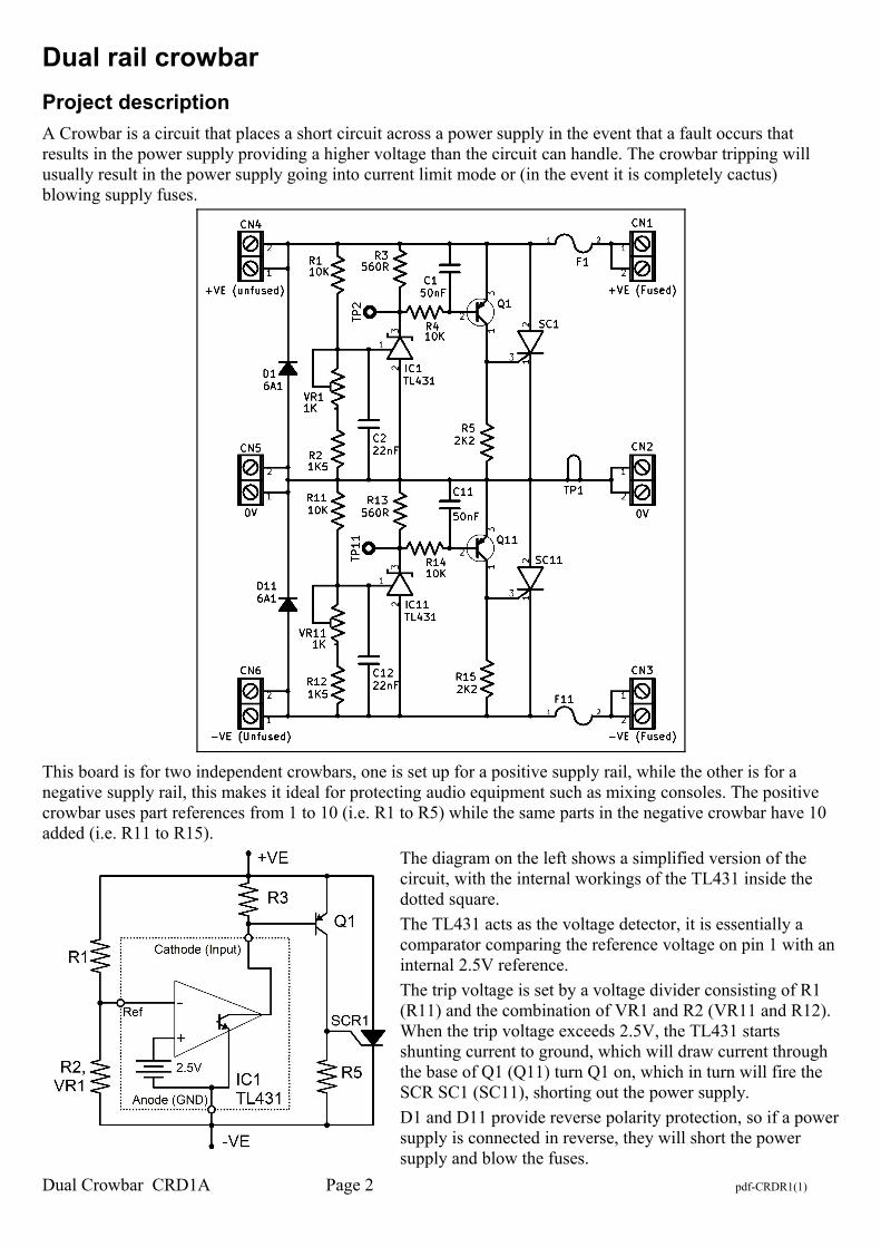
A Crowbar is a circuit that places a short circuit across a power supply in the event that a fault occurs that results in the power supply providing a higher voltage than the circuit can handle. The crowbar tripping will usually result in the power supply going into current limit mode or (in the event it is completely cactus) blowing supply fuses.
This board is for two independent crowbars, one is set up for a positive supply rail, while the other is for a negative supply rail, this makes it ideal for protecting audio equipment such as mixing consoles. The positive crowbar uses part references from 1 to 10 (i.e. R1 to R5) while the same parts in the negative crowbar have 10 added (i.e. R11 to R15).
The diagram on the left shows a simplified version of the circuit, with the internal workings of the TL431 inside the dotted square.
The TL431 acts as the voltage detector, it is essentially a comparator comparing the reference voltage on pin 1 with an internal 2.5V reference.
The trip voltage is set by a voltage divider consisting of R1 (R11) and the combination of VR1 and R2 (VR11 and R12). When the trip voltage exceeds 2.5V, the TL431 starts shunting current to ground, which will draw current through the base of Q1 (Q11) turn Q1 on, which in turn will fire the SCR SC1 (SC11), shorting out the power supply.
D1 and D11 provide reverse polarity protection, so if a powersupply is connected in reverse, they will short the power supply and blow the fuses.
Dual Crowbar CRD1A Page 2 pdf-CRDR1(1)
Note that once triggered, the crowbar will remain tripped until it loses power completely, either due to the fuse blowing, or the power supply being switched off.
Capacitor C1 (C11) helps ensure that Q1 (Q11) does not come on (and trigger the SCR) when power is first applied to the circuit, between C1 and R4 we have a Time constant of around ½ mS* which should be more than enough to stop false triggering on power up.
Capacitor C2 decreases the likelihood of short transients or noise triggering the Crowbar, and between C2 and R1 we have a time constant of around ¼ mS.
While we now have a total time constant of around ¾ of a millisecond, this does not mean the circuit will take this long to trip. The time constant merely describes how long a capacitor will take to charge up to 63.2% of charge. In reality, the crowbar will trip before this point, and the worse the over voltage, the quicker the crowbar will trip.
Testing my prototype with component values given here, with the trip voltage set to somewhere around 17.8V (as per below, somewhere between 17.85 and 17.9V) I measured the following trip times;
Input voltage Trigger time
17.85V Did not trip
17.9V 660μS
19V 180μS
22V 120μS
31V 76μS
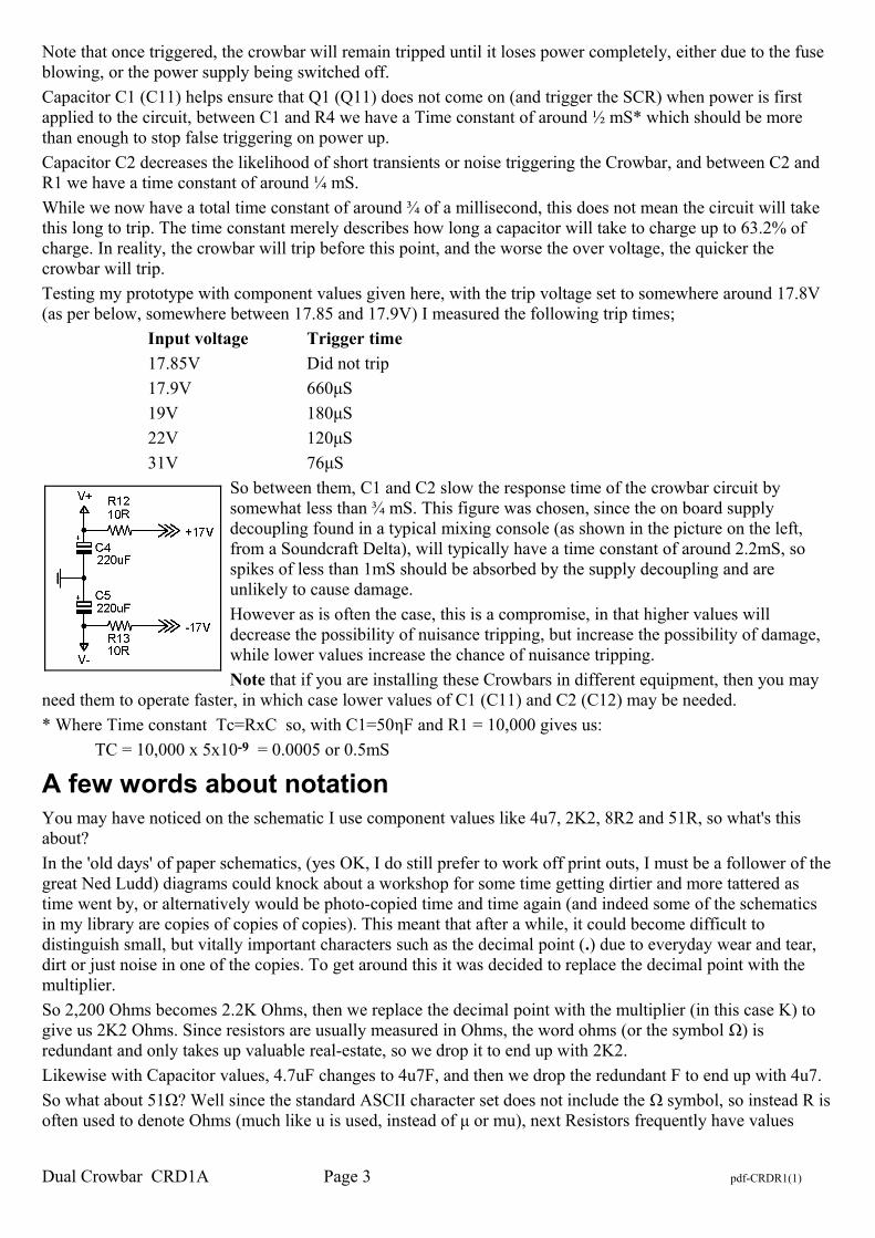
So between them, C1 and C2 slow the response time of the crowbar circuit by somewhat less than ¾ mS. This figure was chosen, since the on board supply decoupling found in a typical mixing console (as shown in the picture on the left, from a Soundcraft Delta), will typically have a time constant of around 2.2mS, so spikes of less than 1mS should be absorbed by the supply decoupling and are unlikely to cause damage.
However as is often the case, this is a compromise, in that higher values will decrease the possibility of nuisance tripping, but increase the possibility of damage, while lower values increase the chance of nuisance tripping.
Note that if you are installing these Crowbars in different equipment, then you may need them to operate faster, in which case lower values of C1 (C11) and C2 (C12) may be needed.
* Where Time constant Tc=RxC so, with C1=50ηF and R1 = 10,000 gives us:
TC = 10,000 x 5x10-9 = 0.0005 or 0.5mS
A few words about notationYou may have noticed on the schematic I use component values like 4u7, 2K2, 8R2 and 51R, so what's this about?
In the 'old days' of paper schematics, (yes OK, I do still prefer to work off print outs, I must be a follower of thegreat Ned Ludd) diagrams could knock about a workshop for some time getting dirtier and more tattered as time went by, or alternatively would be photo-copied time and time again (and indeed some of the schematics in my library are copies of copies of copies). This meant that after a while, it could become difficult to distinguish small, but vitally important characters such as the decimal point (.) due to everyday wear and tear, dirt or just noise in one of the copies. To get around this it was decided to replace the decimal point with the multiplier.
So 2,200 Ohms becomes 2.2K Ohms, then we replace the decimal point with the multiplier (in this case K) to give us 2K2 Ohms. Since resistors are usually measured in Ohms, the word ohms (or the symbol Ω) is redundant and only takes up valuable real-estate, so we drop it to end up with 2K2.
Likewise with Capacitor values, 4.7uF changes to 4u7F, and then we drop the redundant F to end up with 4u7.
So what about 51Ω? Well since the standard ASCII character set does not include the Ω symbol, so instead R isoften used to denote Ohms (much like u is used, instead of μ or mu), next Resistors frequently have values
Dual Crowbar CRD1A Page 3 pdf-CRDR1(1)
greater than 100Ω so we need to clarify that that this is 51 Ohms, rather than say, 51 KΩ, so as an exception to the dropping the unit of measurement rule above, we express this as 51R.
Likewise 8.2Ω, since we have no multiplier and cannot print an Ohms symbol (in ASCII), so R is used instead giving us 8R2.
ConstructionThe entire circuit fits on a single circuit board measuring 60 by 65mm.This should be compact enough to fit into most equipment.
Fit the Resistors first, followed by the capacitors, Diodes, Terminal blocks, Integrated Circuits, Transistors and finally the SCRs.
Provision has been made for a screw mounted metal bracket to hold the SCRs in place, this is advisable where higher current power supplies are in use (say 3 Amps or more) as this will also improve the connection to the Anode of the SCR.
Heatsink
Under normal use the SCRs will dissipate relatively low power, even with the crowbar tripped, so shouldn't need much in the way of heat-sinking.
To calculate required heat-sinking, first we need to calculate the power dissipation in the SCR in tripped state, this depends on the current of the source power supply and the SCR used.
For this example I am going to assume a short circuit current, or ISC of 5 Amps, the SCR is a TYN640, and maximum ambient air temperature, or TA is 45C (not unusual inside equipment).
From the TYN640 data sheet we need the following parameters:
Junction to case Thermal resistance or Rth(j-c) : 0.8C/W
Maximum Junction temperature or TJ : 120CMaximum forward Voltage drop or VTM : 1.2V
Using VTM and ISC, we calculate power dissipation when the SCR is triggered; PDIS = ISC VTM or 6 Watts
if we start with the Junction at 120C, and work outwards, the Temperature of the case, or TC needs to be less than; TC = TJ-(PDIS RTH(J-C)) so ; 120-(6 0.8) = 115.2C.
So now we just need to calculate the desired thermal resistance (to air) of the heatsink or RTH(H), to do this we subtract ambient air temperature from the case temperature and divide the result by the power dissipation of the SCR, so; RTH(H) = (TC – TA) / PDIS, So RTH(H) = (115.2 – 45)/6 = or 11.7C/W and if we allow, say 1C/W for mounting etc, then any heat-sink less than 10C/W would be more than adequate. Of course if you are usingthe fused input the SCR will only need to dissipate power briefly.
While provision has been made for 5mm (0.2”) pitch screw terminals you may decide that these add extra expense and potentially may decrease reliability (particularly if the equipment is to be transported frequently) so I would usually recommend soldering wires directly to the PCB, when and if practical.
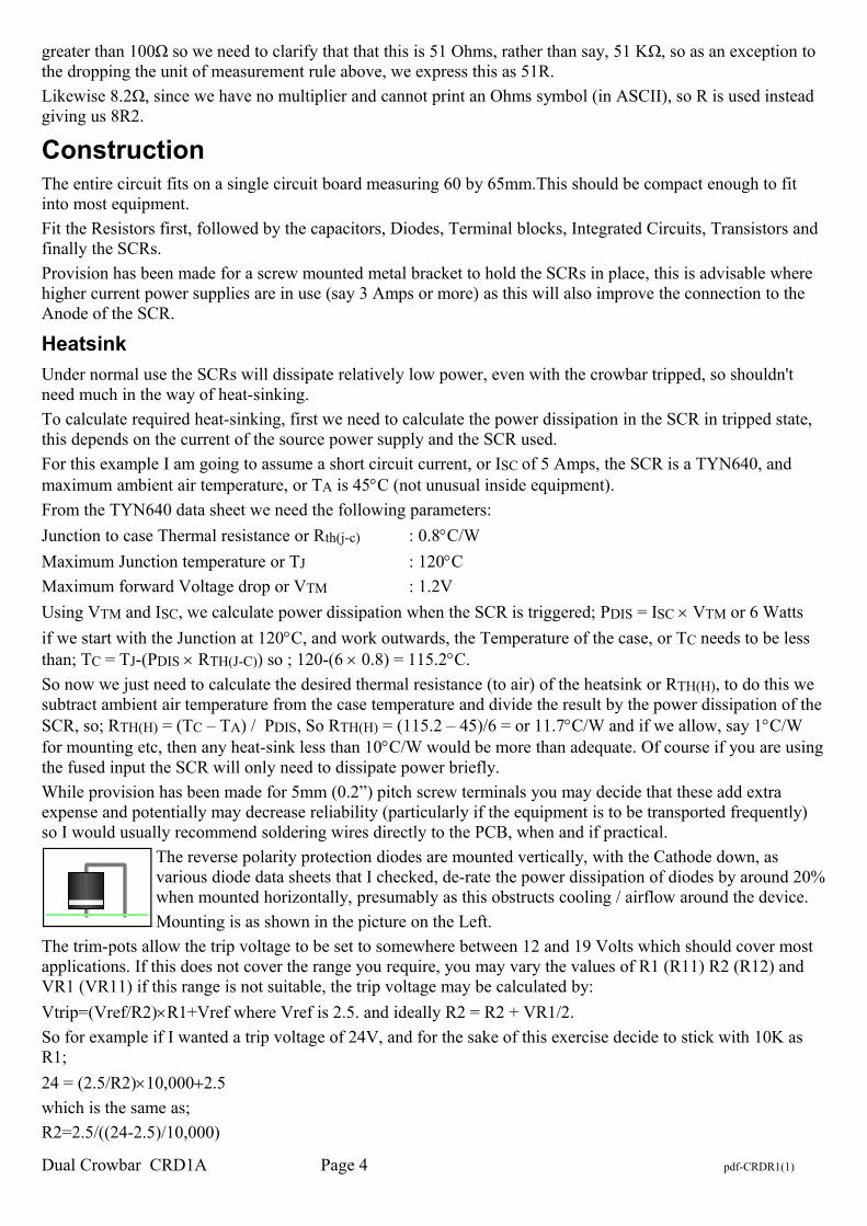
The reverse polarity protection diodes are mounted vertically, with the Cathode down, as various diode data sheets that I checked, de-rate the power dissipation of diodes by around 20%when mounted horizontally, presumably as this obstructs cooling / airflow around the device.
Mounting is as shown in the picture on the Left.
The trim-pots allow the trip voltage to be set to somewhere between 12 and 19 Volts which should cover most applications. If this does not cover the range you require, you may vary the values of R1 (R11) R2 (R12) and VR1 (VR11) if this range is not suitable, the trip voltage may be calculated by:
Vtrip=(Vref/R2)R1+Vref where Vref is 2.5. and ideally R2 = R2 + VR1/2.
So for example if I wanted a trip voltage of 24V, and for the sake of this exercise decide to stick with 10K as R1;
24 = (2.5/R2)10,0002.5
which is the same as;
R2=2.5/((24-2.5)/10,000)
Dual Crowbar CRD1A Page 4 pdf-CRDR1(1)
so R2 = 1,162 ohms, now ideally we want VR to be set somewhere around the middle, or 500 leaving 662 for R2, so we would go for the nearest E24 value of 680, alternatively since VR1=1K was selected more to provide a wide range of trip voltages rather than accuracy, you may choose to go with R2=1,100 and VR2=100
Note the maximum voltage the TL431 can handle is 36V, so this circuit is not suitable for supplies over 36 Volts per rail.
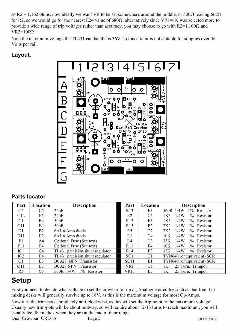
Layout.
Parts locator
Part Location Description Part Location DescriptionC2 C5 22nF R13 E3 560R 1/4W 1% ResistorC12 E5 22nF R2 C5 1K5 1/4W 1% ResistorC1 B4 50nF R12 E5 1K5 1/4W 1% ResistorC11 E4 50nF R15 F2 2K2 1/4W 1% ResistorD1 B2 6A1 6 Amp diode R5 D2 2K2 1/4W 1% ResistorD11 E2 6A1 6 Amp diode R1 C4 10K 1/4W 1% ResistorF1 A4 Optional Fuse (See text) R4 C3 33K 1/4W 1% Resistor
F11 F4 Optional Fuse (See text) R11 E4 10K 1/4W 1% ResistorIC1 C4 TL431 precision shunt regulator R14 E3 33K 1/4W 1% ResistorIC2 E4 TL431 precision shunt regulator SC1 C1 TYN640 (or equivalent) SCRQ1 B3 BC327 NPN Transistor SC11 E1 TYN640 (or equivalent) SCRQ11 E3 BC327 NPN Transistor VR1 C5 1K 25 Turn, TrimpotR3 C3 560R 1/4W 1% Resistor VR11 E5 1K 25 Turn, Trimpot
SetupFirst you need to decide what voltage to set the crowbar to trip at, Analogue circuitry such as that found in mixing desks will generally survive up to 18V, as this is the maximum voltage for most Op-Amps.
Now turn the trim-pots completely anti-clockwise, as this will set the trip point to the maximum voltage. Usually new trim-pots will be about midway, so will require about 12-13 turns to reach maximum, you will usually feel them click when they are at the end of their range.Dual Crowbar CRD1A Page 5 pdf-CRDR1(1)
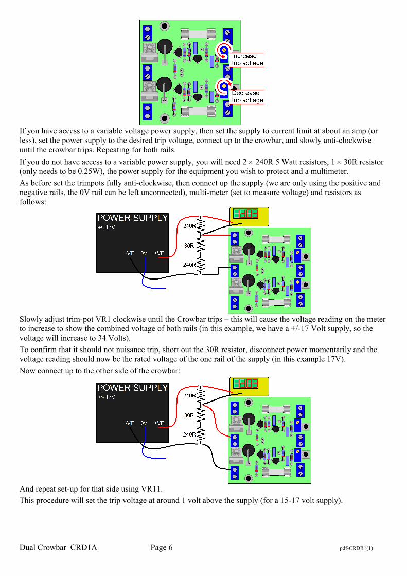
If you have access to a variable voltage power supply, then set the supply to current limit at about an amp (or less), set the power supply to the desired trip voltage, connect up to the crowbar, and slowly anti-clockwise until the crowbar trips. Repeating for both rails.
If you do not have access to a variable power supply, you will need 2 240R 5 Watt resistors, 1 30R resistor (only needs to be 0.25W), the power supply for the equipment you wish to protect and a multimeter.
As before set the trimpots fully anti-clockwise, then connect up the supply (we are only using the positive and negative rails, the 0V rail can be left unconnected), multi-meter (set to measure voltage) and resistors as follows:
Slowly adjust trim-pot VR1 clockwise until the Crowbar trips – this will cause the voltage reading on the meter to increase to show the combined voltage of both rails (in this example, we have a +/-17 Volt supply, so the voltage will increase to 34 Volts).
To confirm that it should not nuisance trip, short out the 30R resistor, disconnect power momentarily and the voltage reading should now be the rated voltage of the one rail of the supply (in this example 17V).
Now connect up to the other side of the crowbar:
And repeat set-up for that side using VR11.
This procedure will set the trip voltage at around 1 volt above the supply (for a 15-17 volt supply).
Dual Crowbar CRD1A Page 6 pdf-CRDR1(1)
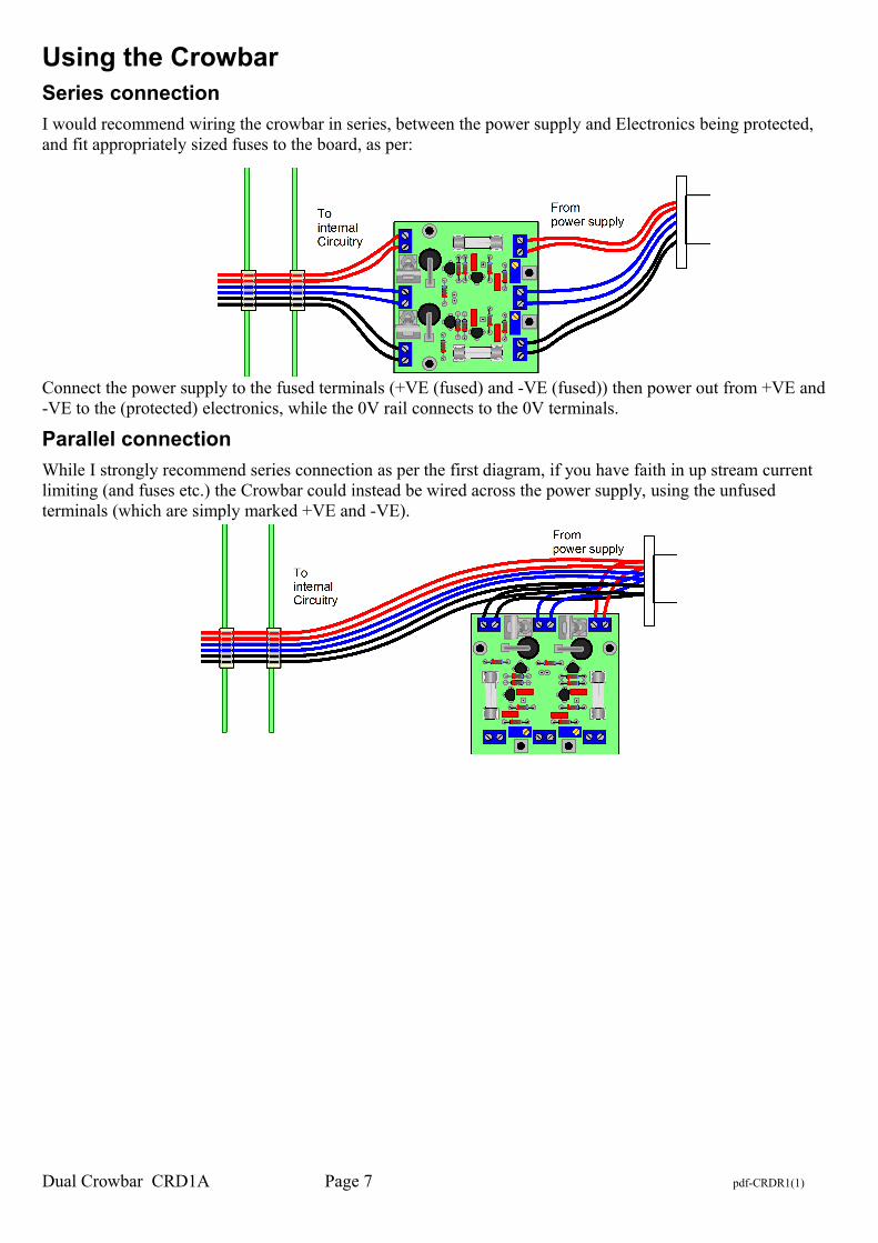
Using the CrowbarSeries connection
I would recommend wiring the crowbar in series, between the power supply and Electronics being protected, and fit appropriately sized fuses to the board, as per:
Connect the power supply to the fused terminals (+VE (fused) and -VE (fused)) then power out from +VE and -VE to the (protected) electronics, while the 0V rail connects to the 0V terminals.
Parallel connection
While I strongly recommend series connection as per the first diagram, if you have faith in up stream current limiting (and fuses etc.) the Crowbar could instead be wired across the power supply, using the unfused terminals (which are simply marked +VE and -VE).
Dual Crowbar CRD1A Page 7 pdf-CRDR1(1)
Parts listThis circuit contains no critical parts and substitutes of components with similar ratings can be made. While 1%metal film resistors are specified and would be preferable for reasons of stability, resistor values are not critical,and the trim-pots will easily compensate for 5% tolerance resistors.
The SCR needs to be able to handle the surge from a failed power supply, this may include discharging filter capacitors. The SCR specified will handle a surge current of 480 Amps, this would assume a resistance of 0.05 ohms on a 25 volt (unregulated) rail in series with the filter capacitors, which is a very conservative assumption given that the ESR of a typical Filter capacitor alone, will be several times that.
The Transistors were chosen for their ability to handle relatively high current (in order to reliably trip the SCR) which could (presuming 36V, being the maximum voltage the TL431 can handle) be in the order of 100 to 630mA although this is of short duration (only until the SCR fires) so it is not expected to result in significant power dissipation in the Transistor.
Qty Ref Description Notes2 C1, C11 56nF MKT capacitor 2 C2, C12 22NF MKT capacitor 2 D1, D11 6A1 6 amp rectifier2 F1, F11 Optional fuse (See text)4 F1, F11 M205 Fuse clips2 IC1, IC2 TL431 precision shunt regulator 2 Q1, Q11 BC327 PNP Transistor2 R1, R11 10K 1/4W 1% Resistor2 R2, R12 1K5 1/4W 1% Resistor2 R3, R13 560R 1/4W 1% Resistor2 R4, R14 33K 1/4W 1% Resistor2 R5, R15 2K2 1/4W 1% Resistor2 SC1, SC11 TYN640 (or equivalent) SCR2 VR1, VR11 1K 25 Turn, Trimpot
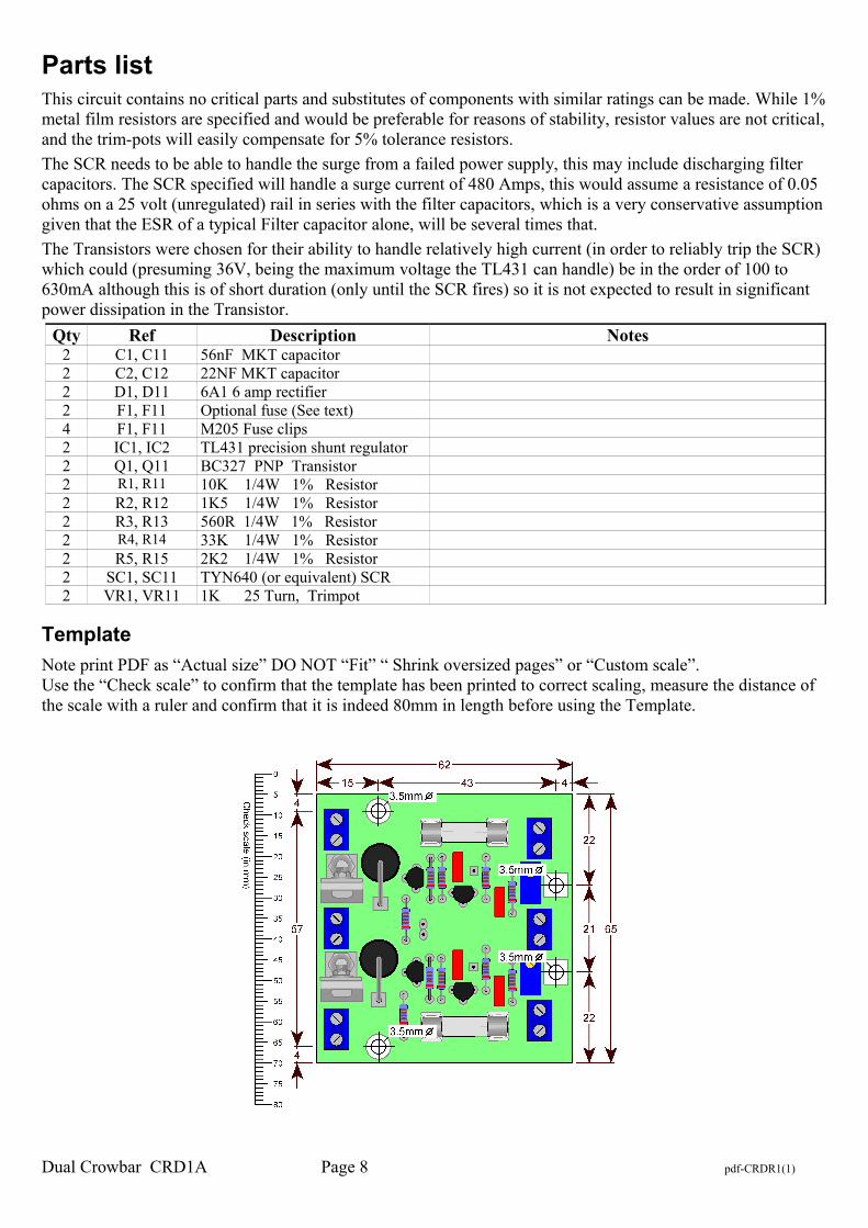
Template
Note print PDF as “Actual size” DO NOT “Fit” “ Shrink oversized pages” or “Custom scale”. Use the “Check scale” to confirm that the template has been printed to correct scaling, measure the distance of the scale with a ruler and confirm that it is indeed 80mm in length before using the Template.
Dual Crowbar CRD1A Page 8 pdf-CRDR1(1)