Embed Size (px)
Citation preview
This article appeared in a journal published by Elsevier. The attachedcopy is furnished to the author for internal non-commercial researchand education use, including for instruction at the authors institution
and sharing with colleagues.
Other uses, including reproduction and distribution, or selling orlicensing copies, or posting to personal, institutional or third party
websites are prohibited.
In most cases authors are permitted to post their version of thearticle (e.g. in Word or Tex form) to their personal website orinstitutional repository. Authors requiring further information
regarding Elsevier’s archiving and manuscript policies areencouraged to visit:
http://www.elsevier.com/copyright

Author's personal copy
Distributed damage creates flaw tolerance
Roberto Ballarini ⇑, Saura Jost, Minmao LiaoDepartment of Civil Engineering, University of Minnesota, United States
a r t i c l e i n f o
Article history:Received 7 December 2010Accepted 23 March 2011Available online 30 March 2011
Keywords:Flaw toleranceSize effectBrittleness
a b s t r a c t
A qualitative micromechanical fracture mechanics model is presented that shows how astructure that is sensitive to the presence of a single crack or hole can be rendered flaw tol-erant by the presence of an interacting distribution of such flaws. The simple model wasinspired by the ductile fracture experienced by the under-designed gusset plates recoveredfrom the I-35W Bridge collapse and by the experimentally measured increase in toughnessof concrete damaged by fire.
� 2011 Elsevier Ltd. All rights reserved.
1. Introduction
This paper is concerned about the toughness of structures containing distributed and interacting flaws (cracks and holesfor example) that fail as a result of the propagation of thin bands, wherein irreversible deformation occurs such as micro-cracking and aggregate interlock in concrete or plasticity in metals. Specific attention is paid to whether the failure is brittleor ductile, an important issue ever since Griffith [1] gave birth to the field of fracture mechanics and revisited recently [2,3].A simple illustrative micromechanics model is used to demonstrate how a structure that is sensitive to the presence of anisolated flaw can be rendered flaw tolerant by the introduction of closely spaced flaws.
2. Model
Before proceeding to the model, a brief review is provided of the coupling between the characteristic dimensions of astructural component and the properties of its constituent material. This is arguably the most useful concept provided byfracture mechanics theories. As a crack extends through a material, the stress concentration along its front gives rise to a‘‘process zone’’ within which irreversible deformation such as microcracking in concrete or plasticity in metals occurs. Manynames, including ‘‘structural size’’, ‘‘characteristic length’’ and ‘‘brittleness number’’ have been given to the parameter b � L/q1, where L is a characteristic dimension of the structural shape, and q1 is the material-dependent length scale which is pro-portional to the extent of the process zone that would develop near the front of a very long crack [4–6]. Theoretical andexperimental results have shown that q1 / Gc E
r2y, where Gc, E and ry represent, respectively, the fracture energy, modulus of
elasticity and yield (or ultimate tensile) strength. If b is relatively small, the nominal strength (defined as the maximum loadcapacity divided by the effective, or uncracked cross-sectional area) of a structure containing a flaw is nearly equal to ry, andtherefore the structure is referred to as flaw tolerant. In other words, the structure is not penalized for the presence of theflaw beyond a reduction in capacity due to a reduced cross-sectional area. If b is large, however, the structure senses thepresence of the flaw, and its nominal strength is much lower than ry. The transition from flaw tolerance to flaw sensitivity,
0013-7944/$ - see front matter � 2011 Elsevier Ltd. All rights reserved.doi:10.1016/j.engfracmech.2011.03.019
⇑ Corresponding author.E-mail address: [email protected] (R. Ballarini).
Engineering Fracture Mechanics 78 (2011) 2004–2009
Contents lists available at ScienceDirect
Engineering Fracture Mechanics
journal homepage: www.elsevier .com/locate /engfracmech

Author's personal copy
which is driven by the intimate coupling between the structural dimensions and material properties and quantified by b, is amanifestation of the size effect, a name given to the dependence on absolute size of the nominal strength of geometricallysimilar structures [5]. We note that Bazant’s size effect law for quasibrittle materials [5] involves an alternative parameterthat accounts for the initial geometry of the cracked structure and thus allows the collapse onto a single curve of experimen-tal data and/or theoretical predictions obtained from different structural geometries. The demonstrations problem presentedin this paper does not involve an initial crack, and therefore all results are presented as functions of b.
The simplest quantitative illustration of the ductile to brittle transition is offered by the Dugdale model [6] of the re-sponse of a very large two dimensional plate containing a crack of instantaneous length, 2a, when it is subjected to a uniformtension, r1 (Fig. 1).
The stress concentration at both crack tips produces a localized region of plastic deformation with extent, q, which inapproximated by a continuous distribution of springs that transfer a stress ry across the top and bottom surfaces of the crackand in turn resist the relative displacement between the crack surfaces. The virtual springs are operative up to a criticalstretch, dcr, at which they rupture. The extent of the plastic (process) zone is such that it eliminates the infinite stressesat the crack tips associated with the elastic solution. This condition requires vanishing of the stress intensity factor, KI, whichfor this configuration is written as:
KI ¼ r1ffiffiffiffiffiffiffiffiffiffiffiffiffiffiffiffiffiffiffipðaþ qÞ
p� 2ry
ffiffiffiffiffiffiffiffiffiffiffiffiaþ q
p
rcos�1 a
aþ q
� �¼ 0 ð1Þ
Nomenclature
dcr critical crack opening displacementdtip crack tip opening displacementq1 characteristic lengthr1 applied stressry yield stressL characteristic structural dimensionGc fracture energyE modulus of elasticityKI stress intensity factora crack lengthR hole radiusD beam depth
Fig. 1. Dudgale model.
R. Ballarini et al. / Engineering Fracture Mechanics 78 (2011) 2004–2009 2005

Author's personal copy
where the first term represents the contribution from the applied loading, and the second is due to the crack surface-pinch-ing springs. Eq. (1) provides.
qa¼ sec
pr1
2ry
� �� 1 ð2Þ
while the normalized opening of the crack at the trailing end of the plastic band, referred to as the crack tip opening displace-ment (CTOD), is given by:
dtip
a¼ 8ry
pElog sec
pr1
2ry
� �� �ð3Þ
The normalized strength of the plate, obtained by setting the CTOD equal to dcr, is obtained as:
r1cr
ry¼ 2
pcos�1ðe�q1=aÞ ð4Þ
where for this case q1 ¼ p8
GcEr2
y¼ p
8Edcry
is the extent of the plastic zone in the limit as the crack length approaches infinity. Eq.
(4) is plotted in Fig. 2 together with the numerical results obtained using the general purpose finite element code ABAQUS[7]. For this structure the crack length is the only available characteristic dimension, i.e. L = a, so that the transition is con-trolled by the brittleness number a/q1. For small values of brittleness number the normalized length of the plastic zone isrelatively large, and the structure is flaw tolerant because the capacity approaches that of a plate with no crack. Large valuesof brittleness number are associated with relatively small plastic zones, the strength is inversely proportional to the squareroot of size as predicted by linear elastic fracture mechanics, and the structure is referred to as flaw sensitive.
Next we apply the Dudgale approach to a simple micromechanics model that illustrates how a distribution of interactingflaws can eliminate the flaw sensitivity of structures with relatively large values of b. The motivation of this study comesfrom two recent and disparate observations. The first involves the failure of the gusset plates that initiated the collapse ofthe I-35W Bridge in Minneapolis, and the second is the experimentally measured reduction in the size effect exhibited byconcrete when it is exposed to very high temperatures.
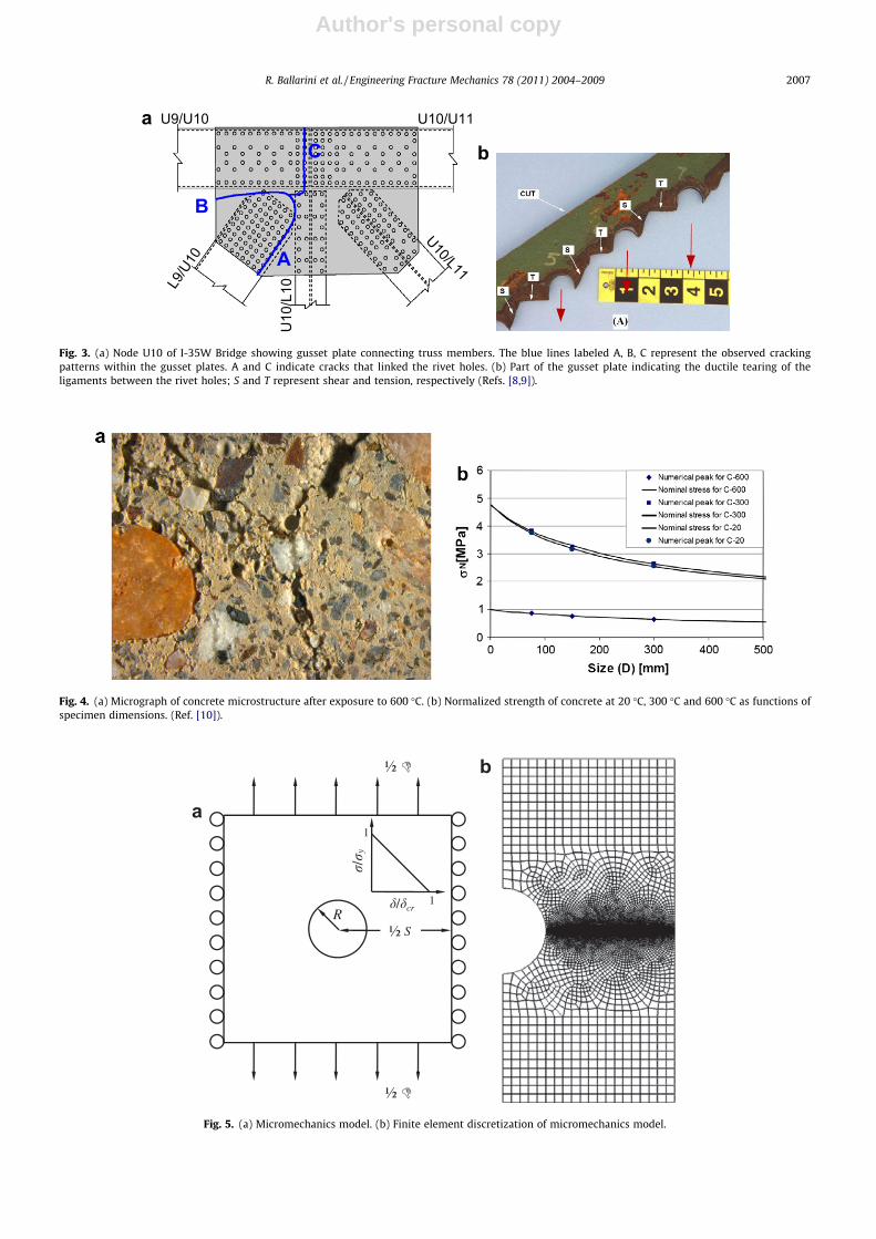
Fig. 3a is a schematic of the U10 node in the steel truss that contained the infamous gusset plates whose failure initiatedthe collapse of the Bridge [8,9]. At least two studies [8,9] have suggested that the gusset plates failed because of a designerror that caused their cross-sectional area to not be sufficiently large to resist the forces it experienced on the day of thecollapse; if the thickness of the gusset plates had been twice as large the Bridge would still be standing. The blue lines inthe drawing represent the cracks that were observed in one of the gusset plates recovered from the wreckage. Fractographicanalyses determined that the coalescence of the rivet holes contained within the gusset plate and shown in Fig. 3b [9] re-sulted from tension and shear induced ductile tearing of the ligaments between the holes. No evidence was found of brittlecracking or subcritical fatigue crack growth. An interesting question is whether plates similar to these containing closelyspaced R-diameter rivet holes and subjected to monotonically increasing forces, would be associated with a size effect if theyare made of a steel with very small values of q (if their toughness (yield strength) was lower (higher)), i.e. if b is significantlylarger. The micromechanics model described subsequently suggests that perforated holes are rendered flaw tolerant whenthe spacing between the holes decreases. It is important to note that in no way do we suggest that cracking could not developis plates containing closely spaced holes. High cycle fatigue is certainly a possibility. But here we focus on static strength.
Fig. 4a shows the diffuse cracking and porosity that develops within the microstructure of concrete after it is heated to600 �C [10]; such damage was not observed in similar specimens exposed to 20 �C and 300 �C. Fig. 4b presents the nominalstrength of geometrically similar notched beam specimens of varying depth, D, that were loaded in three-point bending tofailure after the heat treatments. It was determined by fitting the experimental data to fracture mechanics simulations and
Fig. 2. Normalized strength versus structural size/brittleness predicted by Dugdale model.
2006 R. Ballarini et al. / Engineering Fracture Mechanics 78 (2011) 2004–2009
Author's personal copy
a
b
Fig. 5. (a) Micromechanics model. (b) Finite element discretization of micromechanics model.
A
B
CL9/U10
U9/U10 U10/U11
U10/L10
U10/L11
a
b
Fig. 3. (a) Node U10 of I-35W Bridge showing gusset plate connecting truss members. The blue lines labeled A, B, C represent the observed crackingpatterns within the gusset plates. A and C indicate cracks that linked the rivet holes. (b) Part of the gusset plate indicating the ductile tearing of theligaments between the rivet holes; S and T represent shear and tension, respectively (Refs. [8,9]).
Fig. 4. (a) Micrograph of concrete microstructure after exposure to 600 �C. (b) Normalized strength of concrete at 20 �C, 300 �C and 600 �C as functions ofspecimen dimensions. (Ref. [10]).
R. Ballarini et al. / Engineering Fracture Mechanics 78 (2011) 2004–2009 2007
Author's personal copy
Bazant’s size effect law that the lowest two temperatures are consistent with q1 = 138 mm (20 �C) and q1 = 152 mm (300 �C),and qualitatively similar to the curve shown in Fig. 2. The highest temperature, however, exhibited a very weak size effect (aflattening of the curve within the typical range of brittleness number) consistent with a much larger q1 = 700 mm. What isremarkable about the strength of the concrete exposed to the highest temperature is how much less its strength in the pres-ence of the notch is penalized when its structural dimensions increase. The flattening of the strength–size curve is a result ofthe complex interaction between the initial notch created in the specimen and the surrounding material. There are two pos-sible contributions to the reduction in notch sensitivity at the highest temperature. The first involves the toughening pro-duced by the interaction of the closely spaced pores that are absent at the lower temperatures, and the second is thechemical transformation of calcium silica hydrates that renders the matrix soft. However, both effects can be understoodqualitatively by a reduction in stiffness within a volume, using the simplified micromechanics model presented next.
Consider a periodic arrangement of holes spaced at distance, S, within an infinitely extended plate (Fig. 5a). It is assumedthat ultimate failure results from the coalescence of Dugdale-type cracks that initiate and extend from the edges of the hole.The commercial finite element method code ABAQUS was used to calculate the maximum stress achieved under a monoton-ically increasing applied displacement, D. A representative finite element discretization of the plate is shown in Fig. 5b.Without loss of generality a linear softening stress-crack opening relation typical of concrete, r/ry = (1 � d/dcr), was usedto determine the maximum nominal stress achieved as functions of spacing of the holes and R/q1 (inset of Fig. 5a).
For this example, q1 ¼ Gc Er2
y¼ 1
2Edcry
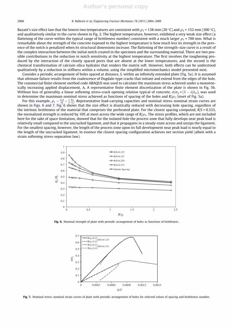
. Representative load-carrying capacities and nominal stress–nominal strain curves areshown in Figs. 6 and 7. Fig. 6 shows that the size effect is drastically reduced with decreasing hole spacing, regardless ofthe intrinsic brittleness of the material that comprises the perforated plate. For the closest spacing computed, R/S = 0.333,the normalized strength is reduced by 10% at most across the wide range of R/q1. The stress profiles, which are not includedhere for the sake of space limitation, showed that for the isolated hole the process zone that fully develops near peak load isrelatively small compared to the uncracked ligament, and that it propagates in a steady-state across and unzips the ligament.For the smallest spacing, however, the length of the process zone upon its full development near peak load is nearly equal tothe length of the uncracked ligament. In essence the closest spacing configuration achieves net section yield (albeit with astrain softening stress-separation law).
Fig. 6. Nominal strength of plate with periodic arrangement of holes as functions of brittleness.
Fig. 7. Nominal stress–nominal strain curves of plate with periodic arrangement of holes for selected values of spacing and brittleness number.
2008 R. Ballarini et al. / Engineering Fracture Mechanics 78 (2011) 2004–2009

Author's personal copy
Fig. 7 shows how the plate’s ductility is influenced by hole spacing. As expected, the response of a plate containing anisolated hole (R/S = 0.125) is ductile (significant energy dissipation post-peak) for relatively small brittleness number (R/q1 = 0.2), but exhibits a steep snap-back brittle response (this curve was truncated because of numerical instability) for largebrittleness number (R/q1 = 2.4). However, for the case of closely spaced holes (R/S = 0.333), the post-peak behavior exhibitedby the isolated hole at the larger value of brittleness number is associated with a much larger amount of energy dissipationas reflected in the stress–strain curve. We note that for this specific flawed plate configuration the response remains unstableunder displacement control, but the increased ductility with decreased spacing is clearly illustrated.
3. Discussion
The simple pedagogical qualitative model presented here has shown that the interaction between flaws can render struc-tures comprised of very brittle materials flaw tolerant, notch insensitivite, and ductile. This insight, which was not the focusof most previous studies that focused on the response of structures containing isolated flaws, can guide the design of struc-tures comprised of inherently brittle materials.
References
[1] Griffith AA. The phenomena of rupture and flow in solids. Philos Trans Roy Soc Lond, Ser A 1921;221:163–98.[2] Gao H, Ji B, Jager IL, Arzt E, Fratzl P. Materials become insensitive to flaws at nanoscale: lessons from nature. PNAS 2003;100:5597–600.[3] Ballarini R, Kayacan R, Ulm FJ, Belytschko T, Heuer AH. Biological structures mitigate fracture through various strategies. Int J Fract 2005;135:187–97.[4] Rice JR. Mathematical analysis in the mechanics of fracture. In: Liebowitz H, editor. Fracture – an advanced treatise, vol. 2. New York: Academic Press;
1968. p. 191–308.[5] Bazant ZP, Planas J. Fracture and size effect in concrete and other quasibrittle materials. CRC Press; 1998.[6] Dugdale DS. Yielding of steel sheets containing slits. J Mech Phys Solids 1960;8:100–4.[7] Simulia. ABAQUS Version 6.8 Documentation Collection, Simulia Corp., Dassault Systemes, Providence, Rhode Island; 2008.[8] Liao M, Okazaki T, Ballarini R, Schultz AE, Galambos TV. Nonlinear finite element analysis of critical gusset plates in the I-35W bridge in minnesota.
ASCE J Struct Eng, posted ahead of print; July 15, 2010. doi: 10.1061/(ASCE)ST.1943-541X.0000269.[9] National Transportation Safety Board (NTSB). Materials laboratory factual report. Report No. 07-119. <http://www.ntsb.gov/dockets/highway/
hwy07mh024/386200.pdf>; December 22, 2008.[10] Di Luzio G, Muciaccia G, Biolzi L. Size effect in thermally damaged concrete. Int J Damage Mech 2010;19(5):631–56.
R. Ballarini et al. / Engineering Fracture Mechanics 78 (2011) 2004–2009 2009