Embed Size (px)
DESCRIPTION
Autodesk 3ds Max 2015 Interface
Citation preview
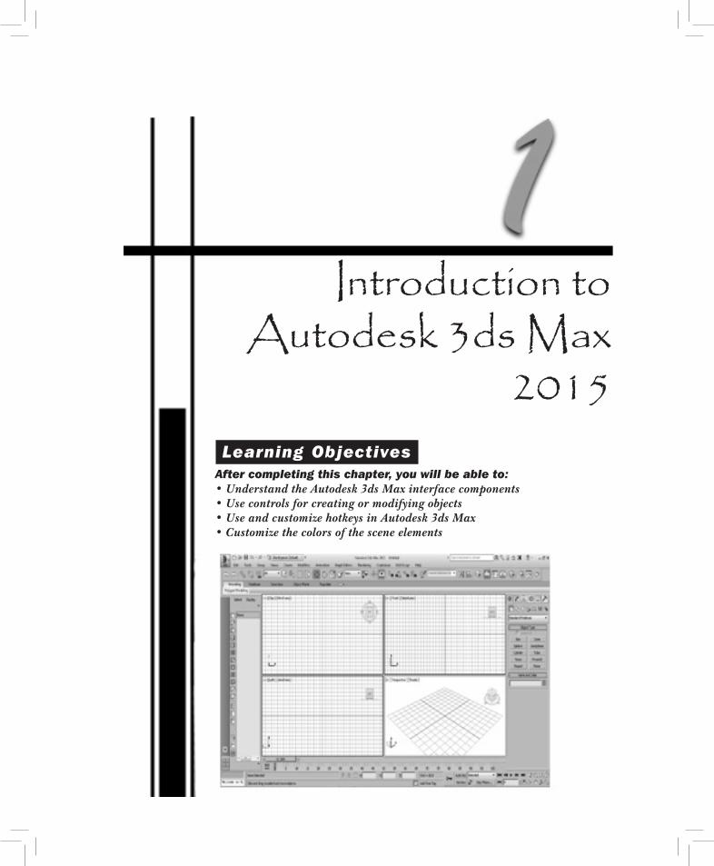
Introduction to Autodesk 3ds Max
2015 Learning ObjectivesAfter completing this chapter, you will be able to:• Understand the Autodesk 3ds Max interface components• Use controls for creating or modifying objects• Use and customize hotkeys in Autodesk 3ds Max• Customize the colors of the scene elements
1-2 Autodesk 3ds Max 2015: A Comprehensive GuideEva
lua
tion
Cop
y. D
o no
t re
prod
uce.
For
inf
orm
ati
on v
isit
ww
w.c
adc
im.c
om
INTRODUCTION TO Autodesk 3ds Max 2015 Welcome to the world of Autodesk 3ds Max, an advanced application that is used to create still or animated 3D models and objects. With the help of this application, you can create realistic scenes by modifying objects, applying maps and materials to a scene, assigning environment to a scene, adding lights and cameras, and so on. Before working with Autodesk 3ds Max, you should have the basic knowledge of various tools and commands available in this software. In this chapter, you will learn the basic features of Autodesk 3ds Max.
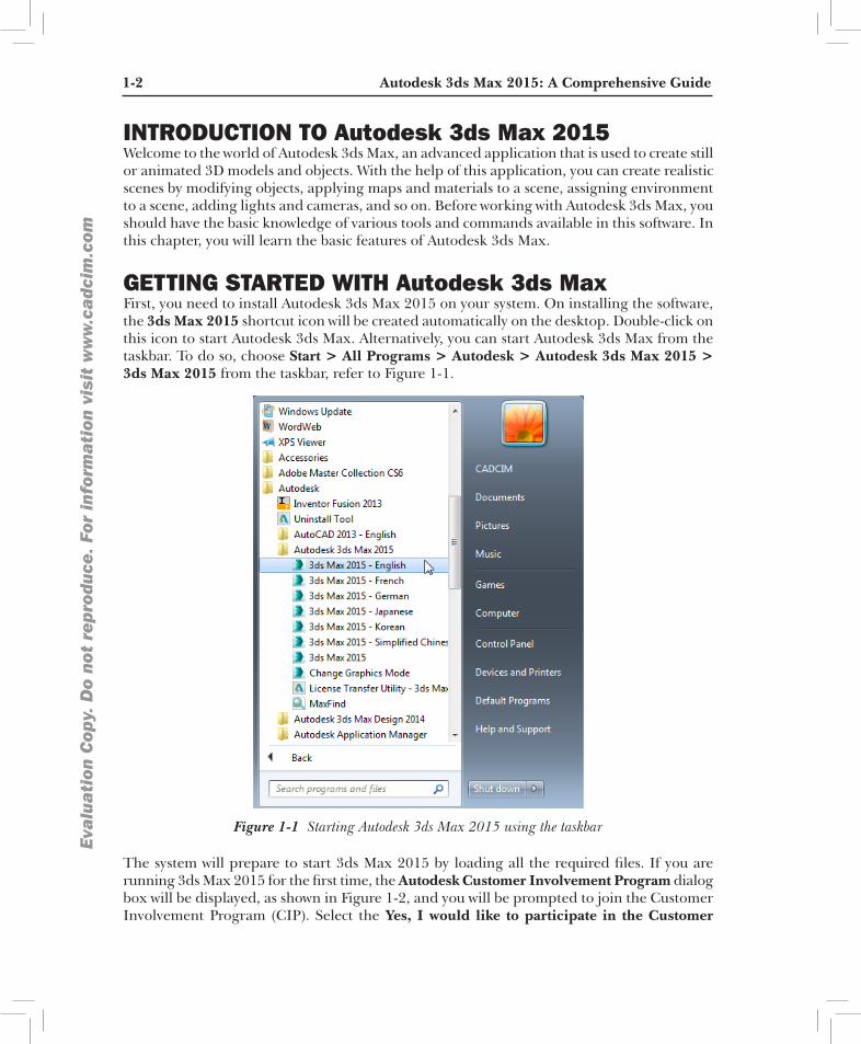
GETTING STARTED WITH Autodesk 3ds Max First, you need to install Autodesk 3ds Max 2015 on your system. On installing the software, the 3ds Max 2015 shortcut icon will be created automatically on the desktop. Double-click on this icon to start Autodesk 3ds Max. Alternatively, you can start Autodesk 3ds Max from the taskbar. To do so, choose Start > All Programs > Autodesk > Autodesk 3ds Max 2015 > 3ds Max 2015 from the taskbar, refer to Figure 1-1.
Figure 1-1 Starting Autodesk 3ds Max 2015 using the taskbar
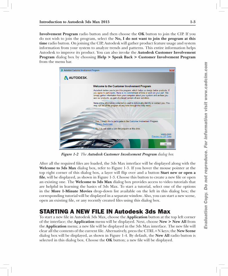
The system will prepare to start 3ds Max 2015 by loading all the required files. If you are running 3ds Max 2015 for the first time, the Autodesk Customer Involvement Program dialog box will be displayed, as shown in Figure 1-2, and you will be prompted to join the Customer Involvement Program (CIP). Select the Yes, I would like to participate in the Customer
Introduction to Autodesk 3ds Max 2015 1-3
Eva
lua
tion
Cop
y. D
o no
t re
prod
uce.
For
inf
orm
ati
on v
isit
ww
w.c
adc
im.c
om
Involvement Program radio button and then choose the OK button to join the CIP. If you do not wish to join the program, select the No, I do not want to join the program at this time radio button. On joining the CIP, Autodesk will gather product feature usage and system information from your system to analyze trends and patterns. This entire information helps Autodesk to improve its product. You can also invoke the Autodesk Customer Involvement Program dialog box by choosing Help > Speak Back > Customer Involvement Program from the menu bar.
Figure 1-2 The Autodesk Customer Involvement Program dialog box
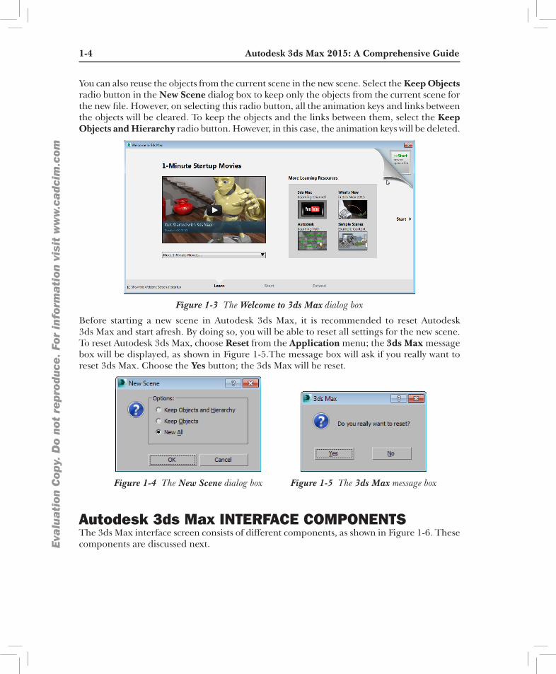
After all the required files are loaded, the 3ds Max interface will be displayed along with the Welcome to 3ds Max dialog box, refer to Figure 1-3. If you hover the mouse pointer at the top right corner of this dialog box, a layer will flip over and a button Start new or open a file, will be displayed, as shown in Figure 1-3. Choose this button to create a new file or open an existing one. The Welcome to 3ds Max dialog box provides access to video tutorials that are helpful in learning the basics of 3ds Max. To start a tutorial, select one of the options in the More 1-Minute Movies drop-down list available on the left in this dialog box; the corresponding tutorial will be displayed in a separate window. Also, you can start a new scene, open an existing file, or any recently created files using this dialog box.
STARTING A NEW FILE IN Autodesk 3ds Max To start a new file in Autodesk 3ds Max, choose the Application button at the top left corner of the interface; the Application menu will be displayed. Next, choose New > New All from the Application menu; a new file will be displayed in the 3ds Max interface. The new file will clear all the contents of the current file. Alternatively, press the CTRL+N keys; the New Scene dialog box will be displayed, as shown in Figure 1-4. By default, the New All radio button is selected in this dialog box. Choose the OK button; a new file will be displayed.
1-4 Autodesk 3ds Max 2015: A Comprehensive GuideEva
lua
tion
Cop
y. D
o no
t re
prod
uce.
For
inf
orm
ati
on v
isit
ww
w.c
adc
im.c
om
You can also reuse the objects from the current scene in the new scene. Select the Keep Objects radio button in the New Scene dialog box to keep only the objects from the current scene for the new file. However, on selecting this radio button, all the animation keys and links between the objects will be cleared. To keep the objects and the links between them, select the Keep Objects and Hierarchy radio button. However, in this case, the animation keys will be deleted.
Figure 1-3 The Welcome to 3ds Max dialog box
Before starting a new scene in Autodesk 3ds Max, it is recommended to reset Autodesk 3ds Max and start afresh. By doing so, you will be able to reset all settings for the new scene. To reset Autodesk 3ds Max, choose Reset from the Application menu; the 3ds Max message box will be displayed, as shown in Figure 1-5.The message box will ask if you really want to reset 3ds Max. Choose the Yes button; the 3ds Max will be reset.
Figure 1-5 The 3ds Max message boxFigure 1-4 The New Scene dialog box
Autodesk 3ds Max INTERFACE COMPONENTSThe 3ds Max interface screen consists of different components, as shown in Figure 1-6. These components are discussed next.

Introduction to Autodesk 3ds Max 2015 1-5
Eva
lua
tion
Cop
y. D
o no
t re
prod
uce.
For
inf
orm
ati
on v
isit
ww
w.c
adc
im.c
om
Figure 1-6 Different screen components of Autodesk 3ds Max interface screen
Menu BarThe menu bar is located just below the title bar, refer to
Figure 1-7 The keyboard shortcuts in the Rendering pull-down menu
Figure 1-6 and contains various pull-down menus. Some of the pull-down menus are standard window menus such as Edit, Help, and so on while others are 3ds Max pull-down menus such as Create, Modifiers, Animation, Graph Editors, Rendering, Customize, and so on. The title of each pull-down menu indicates the purpose of commands in the menu. When you choose one of the menu titles, Autodesk 3ds Max displays the corresponding pull-down menu. Each menu consists of a collection of commands. In a pull-down menu, the dots after a command indicate that a dialog box will be displayed on choosing that command. An arrow next to a command indicates that a cascading menu will be displayed on placing the cursor on that command. For some of the commands in the pull-down menus, the keyboard shortcuts are displayed on their right side, as shown in Figure 1-7.
Application MenuThe Application menu is used to manage the files created in 3ds Max. To display the Application menu, choose the Application button on the top left of the 3ds Max screen. Figure 1-8 displays the Application menu. This menu comprises the most commonly used file management options. The Send to option provides
1-6 Autodesk 3ds Max 2015: A Comprehensive GuideEva
lua
tion
Cop
y. D
o no
t re
prod
uce.
For
inf
orm
ati
on v
isit
ww
w.c
adc
im.c
om
interoperability with other Autodesk applications such as Softimage, MotionBuilder, Maya, and Mudbox. When you choose the Send to option from the Application menu, a cascading menu will be displayed. Choose the desired option from the cascading menu; a submenu will be displayed with the following options: Send as New Scene, Update Current Scene, Add to Current Scene, and Select Previously Sent Objects. You can choose the option from this menu as per your requirement.
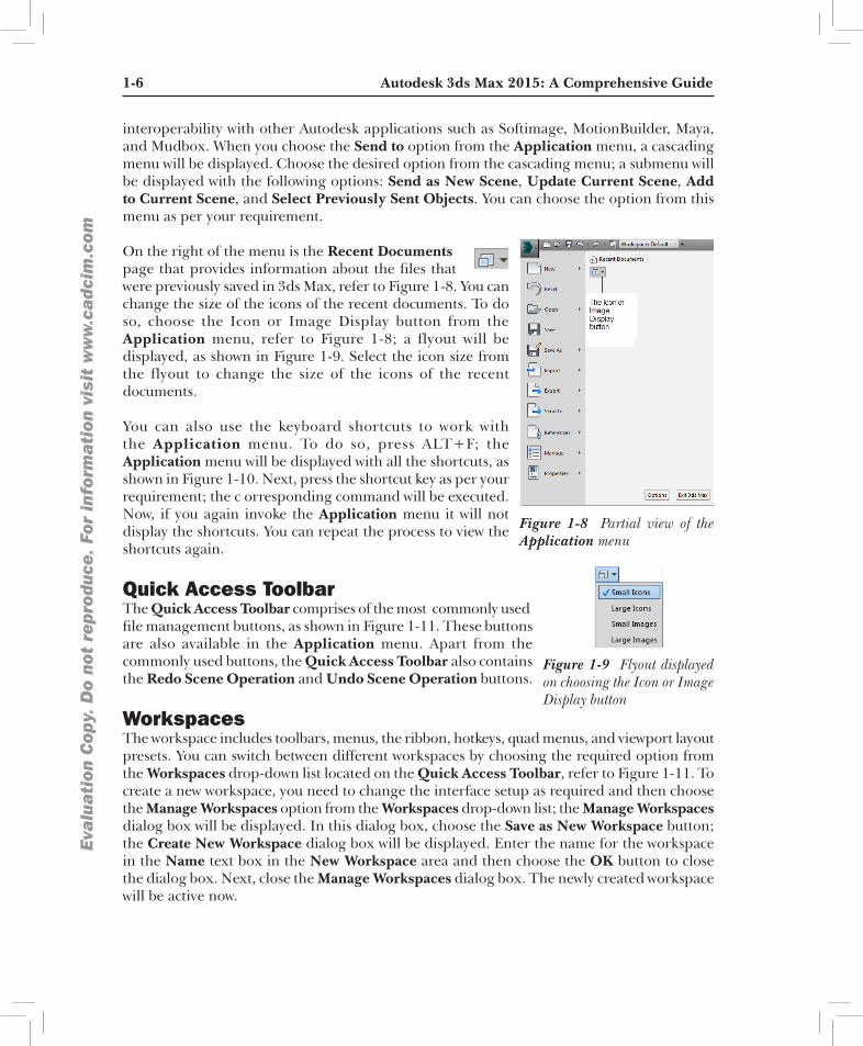
On the right of the menu is the Recent Documents
Figure 1-8 Partial view of the Application menu
page that provides information about the files that were previously saved in 3ds Max, refer to Figure 1-8. You can change the size of the icons of the recent documents. To do so, choose the Icon or Image Display button from the Application menu, refer to Figure 1-8; a flyout will be displayed, as shown in Figure 1-9. Select the icon size from the flyout to change the size of the icons of the recent documents.
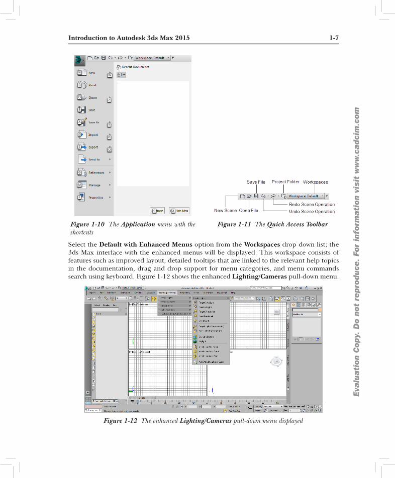
You can also use the keyboard shortcuts to work with the Application menu. To do so, press ALT+F; the Application menu will be displayed with all the shortcuts, as shown in Figure 1-10. Next, press the shortcut key as per your requirement; the c orresponding command will be executed. Now, if you again invoke the Application menu it will not display the shortcuts. You can repeat the process to view the shortcuts again.
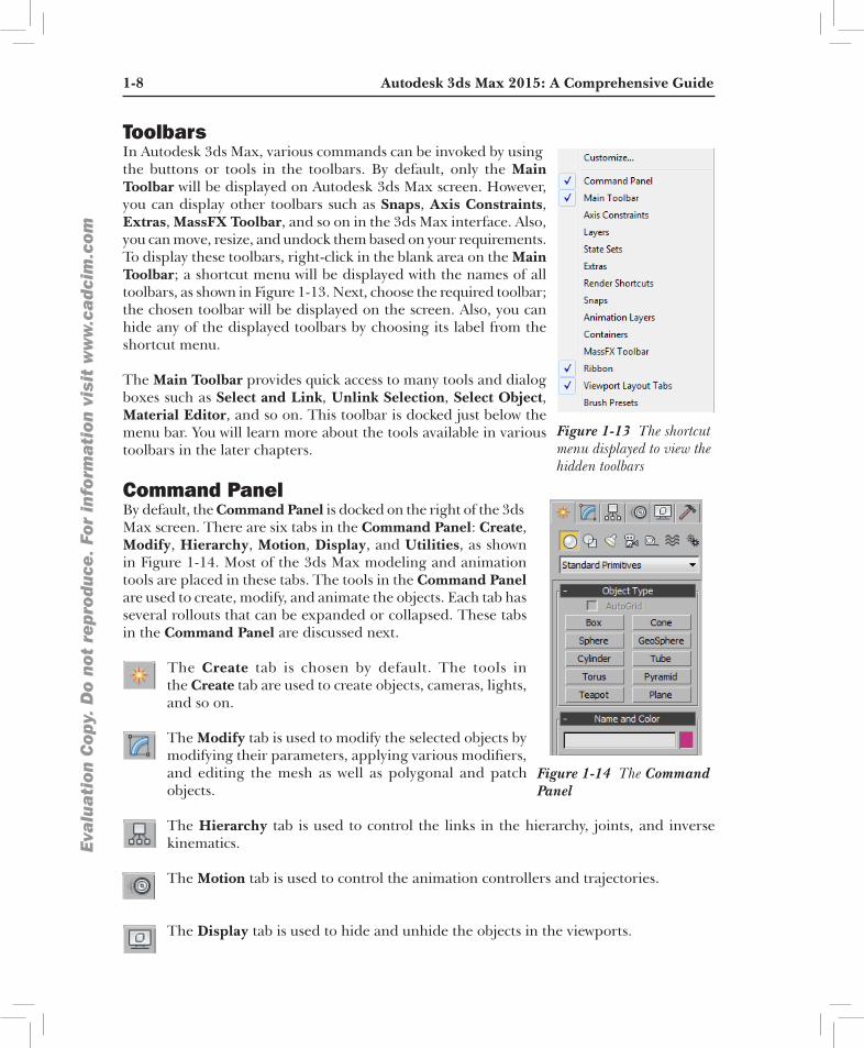
Quick Access ToolbarThe Quick Access Toolbar comprises of the most commonly used
Figure 1-9 Flyout displayed on choosing the Icon or Image Display button
file management buttons, as shown in Figure 1-11. These buttons are also available in the Application menu. Apart from the commonly used buttons, the Quick Access Toolbar also contains the Redo Scene Operation and Undo Scene Operation buttons.
WorkspacesThe workspace includes toolbars, menus, the ribbon, hotkeys, quad menus, and viewport layout presets. You can switch between different workspaces by choosing the required option from the Workspaces drop-down list located on the Quick Access Toolbar, refer to Figure 1-11. To create a new workspace, you need to change the interface setup as required and then choose the Manage Workspaces option from the Workspaces drop-down list; the Manage Workspaces dialog box will be displayed. In this dialog box, choose the Save as New Workspace button; the Create New Workspace dialog box will be displayed. Enter the name for the workspace in the Name text box in the New Workspace area and then choose the OK button to close the dialog box. Next, close the Manage Workspaces dialog box. The newly created workspace will be active now.
Introduction to Autodesk 3ds Max 2015 1-7
Eva
lua
tion
Cop
y. D
o no
t re
prod
uce.
For
inf
orm
ati
on v
isit
ww
w.c
adc
im.c
om
Figure 1-11 The Quick Access ToolbarFigure 1-10 The Application menu with the shortcuts
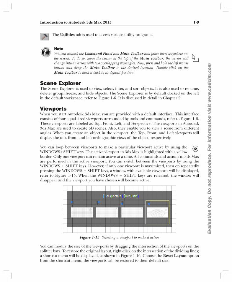
Select the Default with Enhanced Menus option from the Workspaces drop-down list; the 3ds Max interface with the enhanced menus will be displayed. This workspace consists of features such as improved layout, detailed tooltips that are linked to the relevant help topics in the documentation, drag and drop support for menu categories, and menu commands search using keyboard. Figure 1-12 shows the enhanced Lighting/Cameras pull-down menu.
Figure 1-12 The enhanced Lighting/Cameras pull-down menu displayed
1-8 Autodesk 3ds Max 2015: A Comprehensive GuideEva
lua
tion
Cop
y. D
o no
t re
prod
uce.
For
inf
orm
ati
on v
isit
ww
w.c
adc
im.c
om
ToolbarsIn Autodesk 3ds Max, various commands can be invoked by using
Figure 1-13 The shortcut menu displayed to view the hidden toolbars
the buttons or tools in the toolbars. By default, only the Main Toolbar will be displayed on Autodesk 3ds Max screen. However, you can display other toolbars such as Snaps, Axis Constraints, Extras, MassFX Toolbar, and so on in the 3ds Max interface. Also, you can move, resize, and undock them based on your requirements. To display these toolbars, right-click in the blank area on the Main Toolbar; a shortcut menu will be displayed with the names of all toolbars, as shown in Figure 1-13. Next, choose the required toolbar; the chosen toolbar will be displayed on the screen. Also, you can hide any of the displayed toolbars by choosing its label from the shortcut menu.
The Main Toolbar provides quick access to many tools and dialog boxes such as Select and Link, Unlink Selection, Select Object, Material Editor, and so on. This toolbar is docked just below the menu bar. You will learn more about the tools available in various toolbars in the later chapters.
Command Panel By default, the Command Panel is docked on the right of the 3ds
Figure 1-14 The Command Panel
Max screen. There are six tabs in the Command Panel: Create, Modify, Hierarchy, Motion, Display, and Utilities, as shown in Figure 1-14. Most of the 3ds Max modeling and animation tools are placed in these tabs. The tools in the Command Panel are used to create, modify, and animate the objects. Each tab has several rollouts that can be expanded or collapsed. These tabs in the Command Panel are discussed next.
The Create tab is chosen by default. The tools in the Create tab are used to create objects, cameras, lights, and so on.
The Modify tab is used to modify the selected objects by modifying their parameters, applying various modifiers, and editing the mesh as well as polygonal and patch objects.
The Hierarchy tab is used to control the links in the hierarchy, joints, and inverse kinematics.
The Motion tab is used to control the animation controllers and trajectories.
The Display tab is used to hide and unhide the objects in the viewports.
Introduction to Autodesk 3ds Max 2015 1-9
Eva
lua
tion
Cop
y. D
o no
t re
prod
uce.
For
inf
orm
ati
on v
isit
ww
w.c
adc
im.c
om
The Utilities tab is used to access various utility programs.
NoteYou can undock the Command Panel and Main Toolbar and place them anywhere on the screen. To do so, move the cursor at the top of the Main Toolbar; the cursor will change into an arrow with two overlapping rectangles. Now, press and hold the left mouse button and drag the Main Toolbar to the desired location. Double-click on the Main Toolbar to dock it back to its default position.
Scene ExplorerThe Scene Explorer is used to view, select, filter, and sort objects. It is also used to rename, delete, group, freeze, and hide objects. The Scene Explorer is by default docked on the left in the default workspace, refer to Figure 1-6. It is discussed in detail in Chapter 2.
Viewports When you start Autodesk 3ds Max, you are provided with a default interface. This interface consists of four equal sized viewports surrounded by tools and commands, refer to Figure 1-6. These viewports are labeled as Top, Front, Left, and Perspective. The viewports in Autodesk 3ds Max are used to create 3D scenes. Also, they enable you to view a scene from different angles. When you create an object in the viewport, the Top, Front, and Left viewports will display the top, front, and left orthographic views of the object, respectively.
You can loop between viewports to make a particular viewport active by using the WINDOWS+SHIFT keys. The active viewport in 3ds Max is highlighted with a yellow border. Only one viewport can remain active at a time. All commands and actions in 3ds Max are performed in the active viewport. You can switch between the viewports by using the WINDOWS + SHIFT keys. However, if only one viewport is maximized, then on repeatedly pressing the WINDOWS + SHIFT keys, a window with available viewports will be displayed, refer to Figure 1-15. When the WINDOWS + SHIFT keys are released, the window will disappear and the viewport you have chosen will become active.
Figure 1-15 Selecting a viewport to make it active
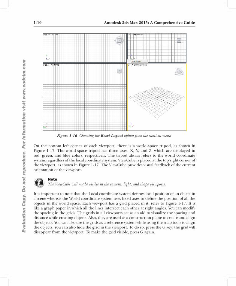
You can modify the size of the viewports by dragging the intersection of the viewports on the splitter bars. To restore the original layout, right-click on the intersection of the dividing lines; a shortcut menu will be displayed, as shown in Figure 1-16. Choose the Reset Layout option from the shortcut menu; the viewports will be restored to their default size.
1-10 Autodesk 3ds Max 2015: A Comprehensive GuideEva
lua
tion
Cop
y. D
o no
t re
prod
uce.
For
inf
orm
ati
on v
isit
ww
w.c
adc
im.c
om
Figure 1-16 Choosing the Reset Layout option from the shortcut menu
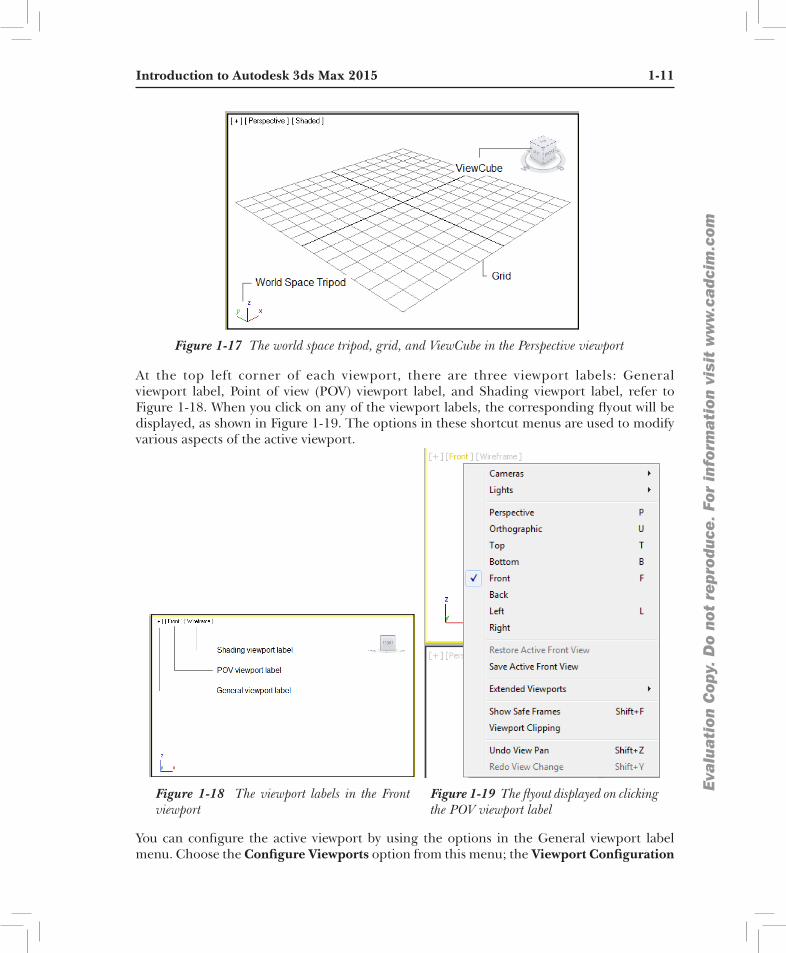
On the bottom left corner of each viewport, there is a world-space tripod, as shown in Figure 1-17. The world-space tripod has three axes, X, Y, and Z, which are displayed in red, green, and blue colors, respectively. The tripod always refers to the world coordinate system,regardless of the local coordinate system. ViewCube is placed at the top right corner of the viewport, as shown in Figure 1-17. The ViewCube provides visual feedback of the current orientation of the viewport.
NoteThe ViewCube will not be visible in the camera, light, and shape viewports.
It is important to note that the Local coordinate system defines local position of an object in a scene whereas the World coordinate system uses fixed axes to define the position of all the objects in the world space. Each viewport has a grid placed in it, refer to Figure 1-17. It is like a graph paper in which all the lines intersect each other at right angles. You can modify the spacing in the grids. The grids in all viewports act as an aid to visualize the spacing and distance while creating objects. Also, they are used as a construction plane to create and align the objects. You can also use the grids as a reference system while using the snap tools to align the objects. You can also hide the grid in the viewport. To do so, press the G key; the grid will disappear from the viewport. To make the grid visible, press G again.
Introduction to Autodesk 3ds Max 2015 1-11
Eva
lua
tion
Cop
y. D
o no
t re
prod
uce.
For
inf
orm
ati
on v
isit
ww
w.c
adc
im.c
om
Figure 1-17 The world space tripod, grid, and ViewCube in the Perspective viewport
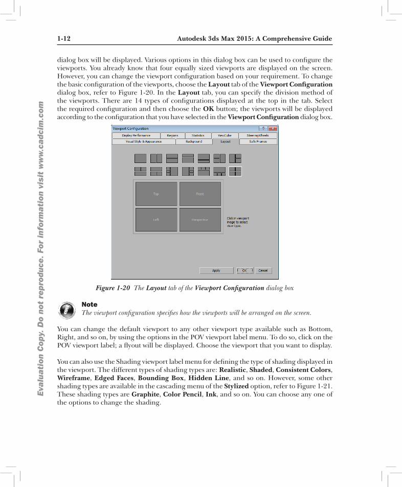
At the top left corner of each viewport, there are three viewport labels: General viewport label, Point of view (POV) viewport label, and Shading viewport label, refer to Figure 1-18. When you click on any of the viewport labels, the corresponding flyout will be displayed, as shown in Figure 1-19. The options in these shortcut menus are used to modify various aspects of the active viewport.
Figure 1-18 The viewport labels in the Front viewport
Figure 1-19 The flyout displayed on clicking the POV viewport label
You can configure the active viewport by using the options in the General viewport label menu. Choose the Configure Viewports option from this menu; the Viewport Configuration
1-12 Autodesk 3ds Max 2015: A Comprehensive GuideEva
lua
tion
Cop
y. D
o no
t re
prod
uce.
For
inf
orm
ati
on v
isit
ww
w.c
adc
im.c
om
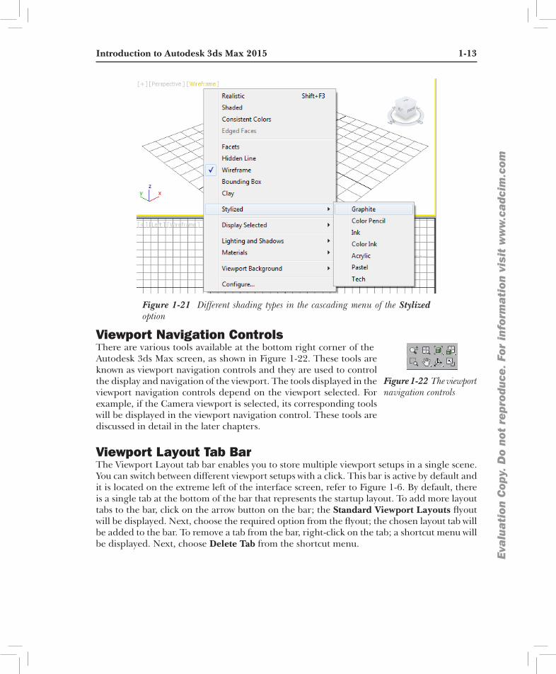
dialog box will be displayed. Various options in this dialog box can be used to configure the viewports. You already know that four equally sized viewports are displayed on the screen. However, you can change the viewport configuration based on your requirement. To change the basic configuration of the viewports, choose the Layout tab of the Viewport Configuration dialog box, refer to Figure 1-20. In the Layout tab, you can specify the division method of the viewports. There are 14 types of configurations displayed at the top in the tab. Select the required configuration and then choose the OK button; the viewports will be displayed according to the configuration that you have selected in the Viewport Configuration dialog box.
Figure 1-20 The Layout tab of the Viewport Configuration dialog box
NoteThe viewport configuration specifies how the viewports will be arranged on the screen.
You can change the default viewport to any other viewport type available such as Bottom, Right, and so on, by using the options in the POV viewport label menu. To do so, click on the POV viewport label; a flyout will be displayed. Choose the viewport that you want to display.
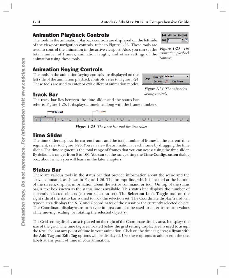
You can also use the Shading viewport label menu for defining the type of shading displayed in the viewport. The different types of shading types are: Realistic, Shaded, Consistent Colors, Wireframe, Edged Faces, Bounding Box, Hidden Line, and so on. However, some other shading types are available in the cascading menu of the Stylized option, refer to Figure 1-21. These shading types are Graphite, Color Pencil, Ink, and so on. You can choose any one of the options to change the shading.
Introduction to Autodesk 3ds Max 2015 1-13
Eva
lua
tion
Cop
y. D
o no
t re
prod
uce.
For
inf
orm
ati
on v
isit
ww
w.c
adc
im.c
om
Figure 1-21 Different shading types in the cascading menu of the Stylized option
Viewport Navigation ControlsThere are various tools available at the bottom right corner of the
Figure 1-22 The viewport navigation controls
Autodesk 3ds Max screen, as shown in Figure 1-22. These tools are known as viewport navigation controls and they are used to control the display and navigation of the viewport. The tools displayed in the viewport navigation controls depend on the viewport selected. For example, if the Camera viewport is selected, its corresponding tools will be displayed in the viewport navigation control. These tools are discussed in detail in the later chapters.
Viewport Layout Tab BarThe Viewport Layout tab bar enables you to store multiple viewport setups in a single scene. You can switch between different viewport setups with a click. This bar is active by default and it is located on the extreme left of the interface screen, refer to Figure 1-6. By default, there is a single tab at the bottom of the bar that represents the startup layout. To add more layout tabs to the bar, click on the arrow button on the bar; the Standard Viewport Layouts flyout will be displayed. Next, choose the required option from the flyout; the chosen layout tab will be added to the bar. To remove a tab from the bar, right-click on the tab; a shortcut menu will be displayed. Next, choose Delete Tab from the shortcut menu.
1-14 Autodesk 3ds Max 2015: A Comprehensive GuideEva
lua
tion
Cop
y. D
o no
t re
prod
uce.
For
inf
orm
ati
on v
isit
ww
w.c
adc
im.c
om
Animation Playback ControlsThe tools in the animation playback controls are displayed on the left side
Figure 1-23 The animation playback controls
of the viewport navigation controls, refer to Figure 1-23. These tools are used to control the animation in the active viewport. Also, you can set the total number of frames, animation length, and other settings of the animation using these tools.
Animation Keying ControlsThe tools in the animation keying controls are displayed on the
Figure 1-24 The animation keying controls
left side of the animation playback controls, refer to Figure 1-24. These tools are used to enter or exit different animation modes.
Track BarThe track bar lies between the time slider and the status bar, refer to Figure 1-25. It displays a timeline along with the frame numbers.
Figure 1-25 The track bar and the time slider
Time SliderThe time slider displays the current frame and the total number of frames in the current time segment, refer to Figure 1-25. You can view the animation at each frame by dragging the time slider. The time segment is the total range of frames that you can access using the time slider. By default, it ranges from 0 to 100. You can set the range using the Time Configuration dialog box, about which you will learn in the later chapters.
Status BarThere are various tools in the status bar that provide information about the scene and the active command, as shown in Figure 1-26. The prompt line, which is located at the bottom of the screen, displays information about the active command or tool. On top of the status bar, a text box known as the status line is available. This status line displays the number of currently selected objects (current selection set). The Selection Lock Toggle tool on the right side of the status bar is used to lock the selection set. The Coordinate display/transform type-in area displays the X, Y, and Z coordinates of the cursor or the currently selected object. The Coordinate display/transform type-in area can also be used to enter transform values while moving, scaling, or rotating the selected object(s).
The Grid setting display area is placed on the right of the Coordinate display area. It displays the size of the grid. The time tag area located below the grid setting display area is used to assign the text labels at any point of time in your animation. Click on the time tag area; a flyout with the Add Tag and Edit Tag options will be displayed. Use these options to add or edit the text labels at any point of time in your animation.

Introduction to Autodesk 3ds Max 2015 1-15
Eva
lua
tion
Cop
y. D
o no
t re
prod
uce.
For
inf
orm
ati
on v
isit
ww
w.c
adc
im.c
omFigure 1-26 The status bar
The Progressive Display/Adaptive Degradation button placed on the right of the prompt line is used to improve the viewport performance in a complex scene by decreasing the visual fidelity of some of the objects temporarily. This results in smoother viewport motions and object transformations in such scenes. It also improves viewport quality incrementally, depending on the availability of processing time. To activate this feature, right-click on the Progressive Display button; the Viewport Configuration dialog box will be displayed, as shown in Figure 1-27. The Display Performance tab is chosen by default in this dialog box. Now, change the settings in the Display Performance tab based on your requirement and choose the OK button.
Figure 1-27 The Viewport Configuration dialog box
1-16 Autodesk 3ds Max 2015: A Comprehensive GuideEva
lua
tion
Cop
y. D
o no
t re
prod
uce.
For
inf
orm
ati
on v
isit
ww
w.c
adc
im.c
om
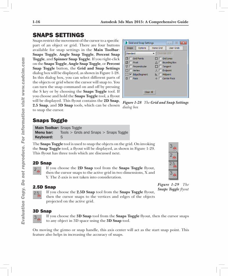
SNAPS SETTINGSSnaps restrict the movement of the cursor to a specific
Figure 1-28 The Grid and Snap Settings dialog box
part of an object or grid. There are four buttons available for snap settings in the Main Toolbar: Snaps Toggle, Angle Snap Toggle, Percent Snap Toggle, and Spinner Snap Toggle. If you right-click on the Snaps Toggle, Angle Snap Toggle, or Percent Snap Toggle button, the Grid and Snap Settings dialog box will be displayed, as shown in Figure 1-28. In this dialog box, you can select different parts of the objects or grid where the cursor will snap to. You can turn the snap command on and off by pressing the S key or by choosing the Snaps Toggle tool. If you choose and hold the Snaps Toggle tool, a flyout will be displayed. This flyout contains the 2D Snap, 2.5 Snap, and 3D Snap tools, which can be chosen to snap the cursor.
Snaps Toggle Main Toolbar: Snaps Toggle Menu bar: Tools > Grids and Snaps > Snaps Toggle Keyboard: S
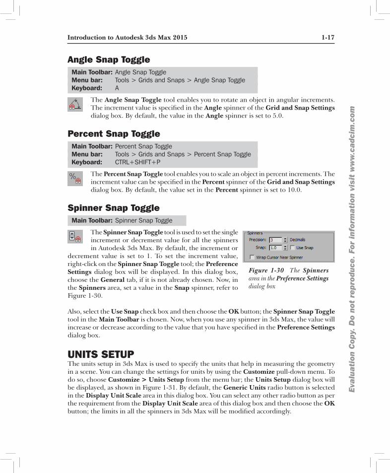
The Snaps Toggle tool is used to snap the objects on the grid. On invoking
Figure 1-29 The Snaps Toggle flyout
the Snap Toggle tool, a flyout will be displayed, as shown in Figure 1-29. This flyout has three tools which are discussed next.
2D SnapIf you choose the 2D Snap tool from the Snaps Toggle flyout, then the cursor snaps to the active grid in two dimensions, X and Y. The Z-axis is not taken into consideration.
2.5D SnapIf you choose the 2.5D Snap tool from the Snaps Toggle flyout, then the cursor snaps to the vertices and edges of the objects projected on the active grid.
3D SnapIf you choose the 3D Snap tool from the Snaps Toggle flyout, then the cursor snaps to any object in 3D space using the 3D Snap tool.
On moving the gizmo or snap handle, this axis center will act as the start snap point. This feature also helps in increasing the accuracy of snaps.
Introduction to Autodesk 3ds Max 2015 1-17
Eva
lua
tion
Cop
y. D
o no
t re
prod
uce.
For
inf
orm
ati
on v
isit
ww
w.c
adc
im.c
om
Angle Snap Toggle Main Toolbar: Angle Snap Toggle Menu bar: Tools > Grids and Snaps > Angle Snap Toggle Keyboard: A
The Angle Snap Toggle tool enables you to rotate an object in angular increments. The increment value is specified in the Angle spinner of the Grid and Snap Settings dialog box. By default, the value in the Angle spinner is set to 5.0.
Percent Snap Toggle Main Toolbar: Percent Snap Toggle Menu bar: Tools > Grids and Snaps > Percent Snap Toggle Keyboard: CTRL+SHIFT+P
The Percent Snap Toggle tool enables you to scale an object in percent increments. The increment value can be specified in the Percent spinner of the Grid and Snap Settings dialog box. By default, the value set in the Percent spinner is set to 10.0.
Spinner Snap Toggle Main Toolbar: Spinner Snap Toggle
The Spinner Snap Toggle tool is used to set the single
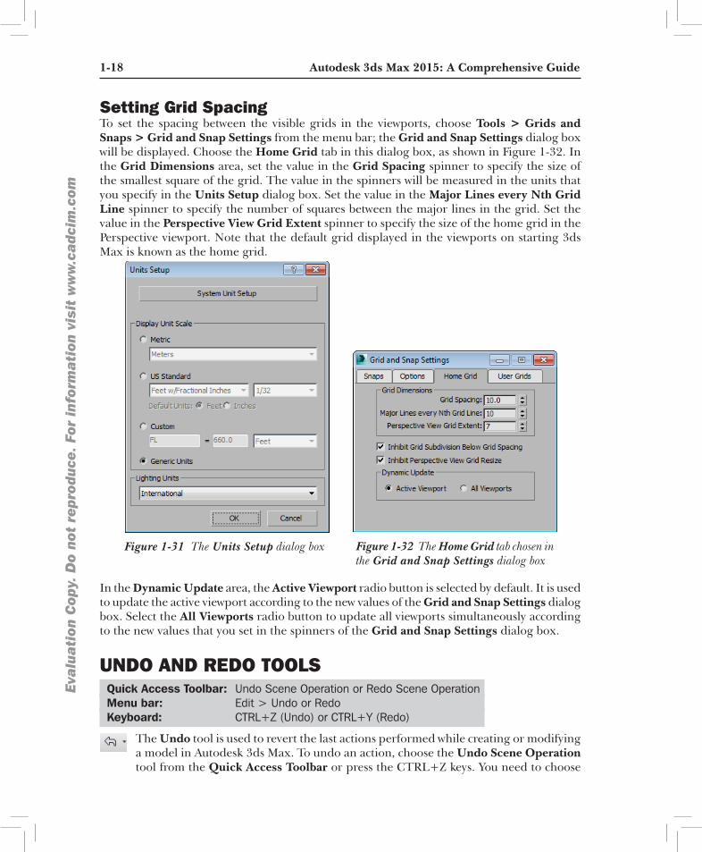
Figure 1-30 The Spinners area in the Preference Settings dialog box
increment or decrement value for all the spinners in Autodesk 3ds Max. By default, the increment or
decrement value is set to 1. To set the increment value, right-click on the Spinner Snap Toggle tool; the Preference Settings dialog box will be displayed. In this dialog box, choose the General tab, if it is not already chosen. Now, in the Spinners area, set a value in the Snap spinner, refer to Figure 1-30.
Also, select the Use Snap check box and then choose the OK button; the Spinner Snap Toggle tool in the Main Toolbar is chosen. Now, when you use any spinner in 3ds Max, the value will increase or decrease according to the value that you have specified in the Preference Settings dialog box.
UNITS SETUP The units setup in 3ds Max is used to specify the units that help in measuring the geometry in a scene. You can change the settings for units by using the Customize pull-down menu. To do so, choose Customize > Units Setup from the menu bar; the Units Setup dialog box will be displayed, as shown in Figure 1-31. By default, the Generic Units radio button is selected in the Display Unit Scale area in this dialog box. You can select any other radio button as per the requirement from the Display Unit Scale area of this dialog box and then choose the OK button; the limits in all the spinners in 3ds Max will be modified accordingly.
1-18 Autodesk 3ds Max 2015: A Comprehensive GuideEva
lua
tion
Cop
y. D
o no
t re
prod
uce.
For
inf
orm
ati
on v
isit
ww
w.c
adc
im.c
om
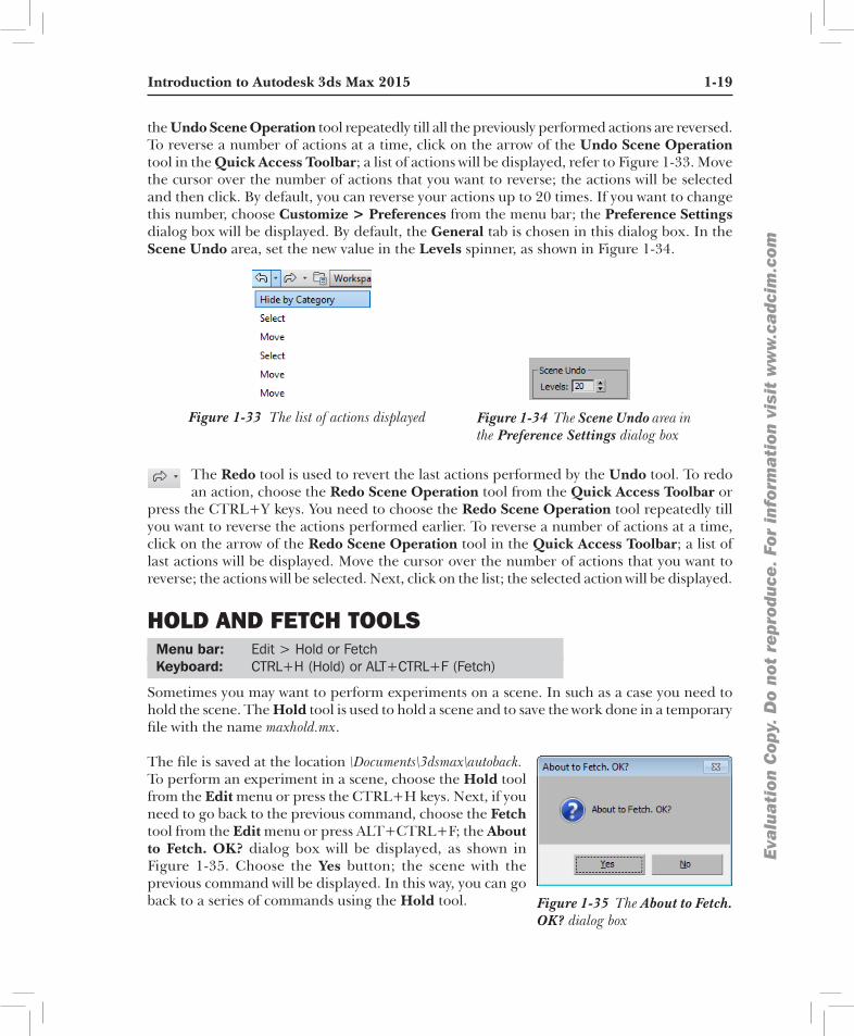
Setting Grid SpacingTo set the spacing between the visible grids in the viewports, choose Tools > Grids and Snaps > Grid and Snap Settings from the menu bar; the Grid and Snap Settings dialog box will be displayed. Choose the Home Grid tab in this dialog box, as shown in Figure 1-32. In the Grid Dimensions area, set the value in the Grid Spacing spinner to specify the size of the smallest square of the grid. The value in the spinners will be measured in the units that you specify in the Units Setup dialog box. Set the value in the Major Lines every Nth Grid Line spinner to specify the number of squares between the major lines in the grid. Set the value in the Perspective View Grid Extent spinner to specify the size of the home grid in the Perspective viewport. Note that the default grid displayed in the viewports on starting 3ds Max is known as the home grid.
Figure 1-32 The Home Grid tab chosen in the Grid and Snap Settings dialog box
Figure 1-31 The Units Setup dialog box
In the Dynamic Update area, the Active Viewport radio button is selected by default. It is used to update the active viewport according to the new values of the Grid and Snap Settings dialog box. Select the All Viewports radio button to update all viewports simultaneously according to the new values that you set in the spinners of the Grid and Snap Settings dialog box.
UNDO AND REDO TOOLS Quick Access Toolbar: Undo Scene Operation or Redo Scene Operation Menu bar: Edit > Undo or Redo Keyboard: CTRL+Z (Undo) or CTRL+Y (Redo)
The Undo tool is used to revert the last actions performed while creating or modifying a model in Autodesk 3ds Max. To undo an action, choose the Undo Scene Operation tool from the Quick Access Toolbar or press the CTRL+Z keys. You need to choose
Introduction to Autodesk 3ds Max 2015 1-19
Eva
lua
tion
Cop
y. D
o no
t re
prod
uce.
For
inf
orm
ati
on v
isit
ww
w.c
adc
im.c
om
the Undo Scene Operation tool repeatedly till all the previously performed actions are reversed. To reverse a number of actions at a time, click on the arrow of the Undo Scene Operation tool in the Quick Access Toolbar; a list of actions will be displayed, refer to Figure 1-33. Move the cursor over the number of actions that you want to reverse; the actions will be selected and then click. By default, you can reverse your actions up to 20 times. If you want to change this number, choose Customize > Preferences from the menu bar; the Preference Settings dialog box will be displayed. By default, the General tab is chosen in this dialog box. In the Scene Undo area, set the new value in the Levels spinner, as shown in Figure 1-34.
Figure 1-33 The list of actions displayed Figure 1-34 The Scene Undo area in the Preference Settings dialog box
The Redo tool is used to revert the last actions performed by the Undo tool. To redo an action, choose the Redo Scene Operation tool from the Quick Access Toolbar or
press the CTRL+Y keys. You need to choose the Redo Scene Operation tool repeatedly till you want to reverse the actions performed earlier. To reverse a number of actions at a time, click on the arrow of the Redo Scene Operation tool in the Quick Access Toolbar; a list of last actions will be displayed. Move the cursor over the number of actions that you want to reverse; the actions will be selected. Next, click on the list; the selected action will be displayed.
HOLD AND FETCH TOOLS Menu bar: Edit > Hold or Fetch Keyboard: CTRL+H (Hold) or ALT+CTRL+F (Fetch)
Sometimes you may want to perform experiments on a scene. In such as a case you need to hold the scene. The Hold tool is used to hold a scene and to save the work done in a temporary file with the name maxhold.mx.
The file is saved at the location \Documents\3dsmax\autoback.
Figure 1-35 The About to Fetch. OK? dialog box
To perform an experiment in a scene, choose the Hold tool from the Edit menu or press the CTRL+H keys. Next, if you need to go back to the previous command, choose the Fetch tool from the Edit menu or press ALT+CTRL+F; the About to Fetch. OK? dialog box will be displayed, as shown in Figure 1-35. Choose the Yes button; the scene with the previous command will be displayed. In this way, you can go back to a series of commands using the Hold tool.
1-20 Autodesk 3ds Max 2015: A Comprehensive GuideEva
lua
tion
Cop
y. D
o no
t re
prod
uce.
For
inf
orm
ati
on v
isit
ww
w.c
adc
im.c
om
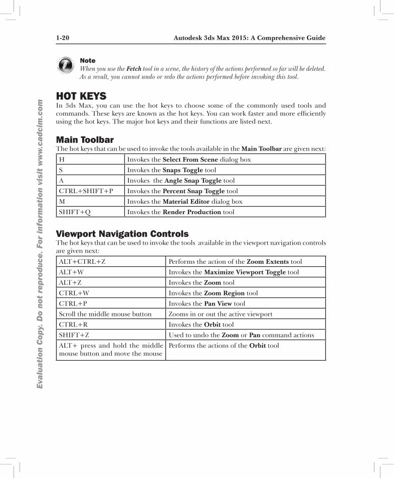
NoteWhen you use the Fetch tool in a scene, the history of the actions performed so far will be deleted. As a result, you cannot undo or redo the actions performed before invoking this tool.
HOT KEYSIn 3ds Max, you can use the hot keys to choose some of the commonly used tools and commands. These keys are known as the hot keys. You can work faster and more efficiently using the hot keys. The major hot keys and their functions are listed next.
Main ToolbarThe hot keys that can be used to invoke the tools available in the Main Toolbar are given next:
H Invokes the Select From Scene dialog box
S Invokes the Snaps Toggle tool
A Invokes the Angle Snap Toggle tool
CTRL+SHIFT+P Invokes the Percent Snap Toggle tool
M Invokes the Material Editor dialog box
SHIFT+Q Invokes the Render Production tool
Viewport Navigation ControlsThe hot keys that can be used to invoke the tools available in the viewport navigation controls are given next:
ALT+CTRL+Z Performs the action of the Zoom Extents tool
ALT+W Invokes the Maximize Viewport Toggle tool
ALT+Z Invokes the Zoom tool
CTRL+W Invokes the Zoom Region tool
CTRL+P Invokes the Pan View tool
Scroll the middle mouse button Zooms in or out the active viewport
CTRL+R Invokes the Orbit tool
SHIFT+Z Used to undo the Zoom or Pan command actions
ALT+ press and hold the middle mouse button and move the mouse
Performs the actions of the Orbit tool
Introduction to Autodesk 3ds Max 2015 1-21
Eva
lua
tion
Cop
y. D
o no
t re
prod
uce.
For
inf
orm
ati
on v
isit
ww
w.c
adc
im.c
om
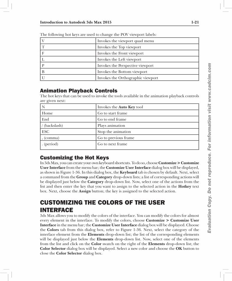
The following hot keys are used to change the POV viewport labels:
V Invokes the viewport quad menu
T Invokes the Top viewport
F Invokes the Front viewport
L Invokes the Left viewport
P Invokes the Perspective viewport
B Invokes the Bottom viewport
U Invokes the Orthographic viewport
Animation Playback ControlsThe hot keys that can be used to invoke the tools available in the animation playback controls are given next:
N Invokes the Auto Key tool
Home Go to start frame
End Go to end frame
/ (backslash) Plays animation
ESC Stop the animation
, (comma) Go to previous frame
. (period) Go to next frame
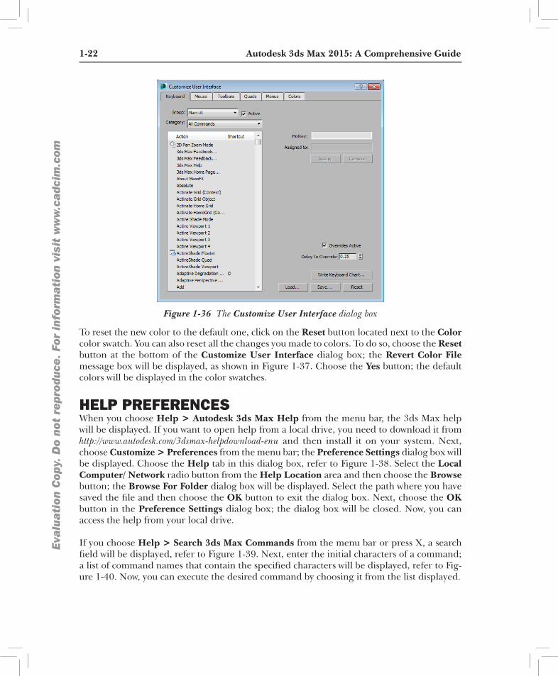
Customizing the Hot KeysIn 3ds Max, you can create your own keyboard shortcuts. To do so, choose Customize > Customize User Interface from the menu bar; the Customize User Interface dialog box will be displayed, as shown in Figure 1-36. In this dialog box, the Keyboard tab is chosen by default. Next, select a command from the Group and Category drop-down lists; a list of corresponding actions will be displayed just below the Category drop-down list. Now, select one of the actions from the list and then enter the key that you want to assign to the selected action in the Hotkey text box. Next, choose the Assign button; the key is assigned to the selected action.
CUSTOMIZING THE COLORS OF THE USER INTERFACE3ds Max allows you to modify the colors of the interface. You can modify the colors for almost every element in the interface. To modify the colors, choose Customize > Customize User Interface in the menu bar; the Customize User Interface dialog box will be displayed. Choose the Colors tab from this dialog box, refer to Figure 1-36. Next, select the category of the interface element from the Elements drop-down list; the list of the corresponding elements will be displayed just below the Elements drop-down list. Now, select one of the elements from the list and click on the Color swatch on the right of the Elements drop-down list; the Color Selector dialog box will be displayed. Select a new color and choose the OK button to close the Color Selector dialog box.
1-22 Autodesk 3ds Max 2015: A Comprehensive GuideEva
lua
tion
Cop
y. D
o no
t re
prod
uce.
For
inf
orm
ati
on v
isit
ww
w.c
adc
im.c
om
Figure 1-36 The Customize User Interface dialog box
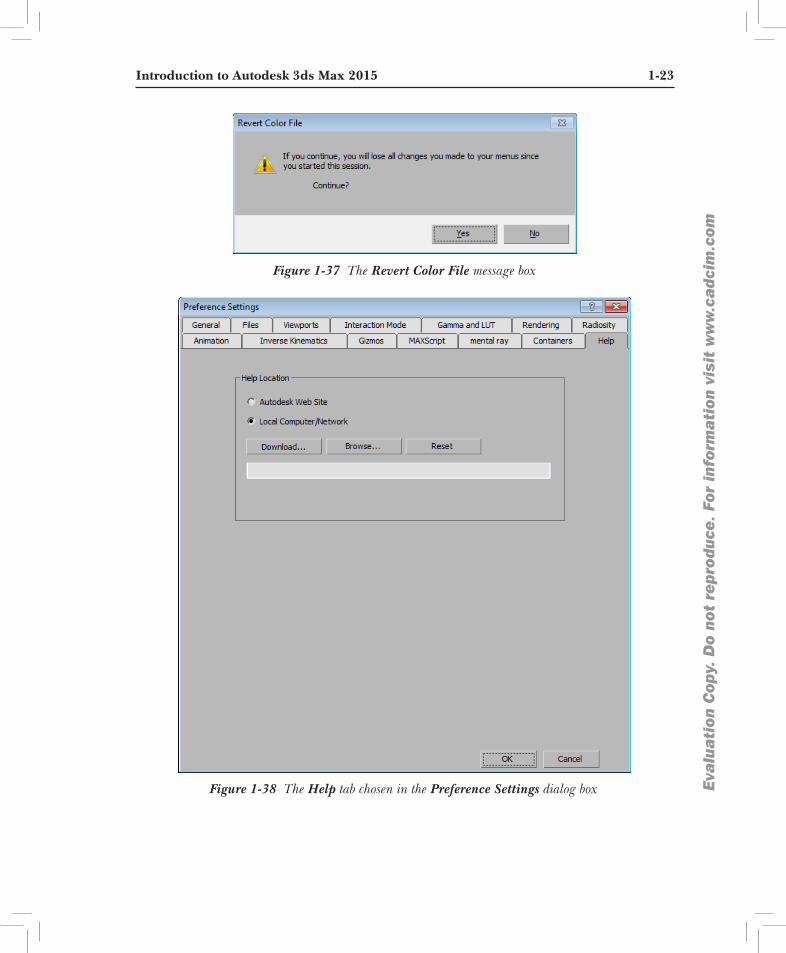
To reset the new color to the default one, click on the Reset button located next to the Color color swatch. You can also reset all the changes you made to colors. To do so, choose the Reset button at the bottom of the Customize User Interface dialog box; the Revert Color File message box will be displayed, as shown in Figure 1-37. Choose the Yes button; the default colors will be displayed in the color swatches.
HELP PREFERENCESWhen you choose Help > Autodesk 3ds Max Help from the menu bar, the 3ds Max help will be displayed. If you want to open help from a local drive, you need to download it from http://www.autodesk.com/3dsmax-helpdownload-enu and then install it on your system. Next, choose Customize > Preferences from the menu bar; the Preference Settings dialog box will be displayed. Choose the Help tab in this dialog box, refer to Figure 1-38. Select the Local Computer/ Network radio button from the Help Location area and then choose the Browse button; the Browse For Folder dialog box will be displayed. Select the path where you have saved the file and then choose the OK button to exit the dialog box. Next, choose the OK button in the Preference Settings dialog box; the dialog box will be closed. Now, you can access the help from your local drive.
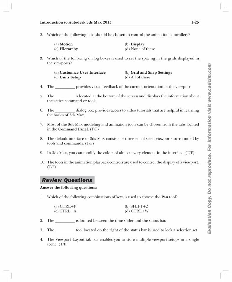
If you choose Help > Search 3ds Max Commands from the menu bar or press X, a search field will be displayed, refer to Figure 1-39. Next, enter the initial characters of a command; a list of command names that contain the specified characters will be displayed, refer to Fig-ure 1-40. Now, you can execute the desired command by choosing it from the list displayed.
Introduction to Autodesk 3ds Max 2015 1-23
Eva
lua
tion
Cop
y. D
o no
t re
prod
uce.
For
inf
orm
ati
on v
isit
ww
w.c
adc
im.c
om
Figure 1-37 The Revert Color File message box
Figure 1-38 The Help tab chosen in the Preference Settings dialog box
1-24 Autodesk 3ds Max 2015: A Comprehensive GuideEva
lua
tion
Cop
y. D
o no
t re
prod
uce.
For
inf
orm
ati
on v
isit
ww
w.c
adc
im.c
om
Figure 1-39 The search field Figure 1-40 List of commands displayed on entering first few characters
NoteFor the printing purpose, this textbook will follow the white background. However, for better understanding and clear visualization, at various places this textbook will follow other color schemes as well.
In addition, the Shaded shading type is used throughout the textbook in all screen captures. Moreover, at some places in figures, grids will be hidden for better understanding and visualization. In some tutorials, you have been instructed to browse the images and max files from the CADCIM website. Therefore, before starting the tutorials, download the images and max files from www.cadcim.com. The path of the files is as follows: Textbooks > Animation and Visual Effects > 3ds Max > Autodesk 3ds Max 2015: A Comprehensive Guide
Self-Evaluation Test Answer the following questions and then compare them to those given at the end of this chapter:
1. Which of the following tools is used to improve the performance of a viewport in a complex scene by temporarily decreasing the visual fidelity of some of the objects?
(a) Progressive Display (b) Snaps Toggle flyout (c) Mirror (d) All of these
Introduction to Autodesk 3ds Max 2015 1-25
Eva
lua
tion
Cop
y. D
o no
t re
prod
uce.
For
inf
orm
ati
on v
isit
ww
w.c
adc
im.c
om
2. Which of the following tabs should be chosen to control the animation controllers?
(a) Motion (b) Display (c) Hierarchy (d) None of these
3. Which of the following dialog boxes is used to set the spacing in the grids displayed in the viewports?
(a) Customize User Interface (b) Grid and Snap Settings (c) Units Setup (d) All of these
4. The __________ provides visual feedback of the current orientation of the viewport.
5. The __________ is located at the bottom of the screen and displays the information about the active command or tool.
6. The __________ dialog box provides access to video tutorials that are helpful in learning the basics of 3ds Max.
7. Most of the 3ds Max modeling and animation tools can be chosen from the tabs located in the Command Panel. (T/F)
8. The default interface of 3ds Max consists of three equal sized viewports surrounded by tools and commands. (T/F)
9. In 3ds Max, you can modify the colors of almost every element in the interface. (T/F)
10. The tools in the animation playback controls are used to control the display of a viewport. (T/F)
Review Questions Answer the following questions:
1. Which of the following combinations of keys is used to choose the Pan tool? (a) CTRL+P (b) SHIFT+Z (c) CTRL+A (d) CTRL+W
2. The __________ is located between the time slider and the status bar.
3. The __________ tool located on the right of the status bar is used to lock a selection set.
4. The Viewport Layout tab bar enables you to store multiple viewport setups in a single scene. (T/F)
1-26 Autodesk 3ds Max 2015: A Comprehensive GuideEva
lua
tion
Cop
y. D
o no
t re
prod
uce.
For
inf
orm
ati
on v
isit
ww
w.c
adc
im.c
om
5. Snapping restricts the movement of the cursor to a specific part of an object or grid. (T/F)
6. The options in the General viewport label menu are used for defining the type of shadings displayed in the viewport. (T/F)
Answers to Self-Evaluation Test1. a, 2. a, 3. b, 4. Viewcube, 5. prompt line, 6. Welcome to 3ds Max, 7. T, 8. F, 9. T, 10. F