Embed Size (px)
Citation preview
ECOLE POLYTECHNIQUE Master 1 MARTINEZ, Lucas Ariel
RAPPORT DE STAGE DE RECHERCHE
Automated code translation: Implementation of a tool to help in the migration of a
.NET solution to Google Web Toolkit
NON CONFIDENTIEL PUBLICATION
Option : INFORMATIQUE Champ de l'option : Software Engineering / Software Development Directeur de l'option : Olivier Bournez Directeur de stage : Cyril Allouche Dates du stage : 4 avril 2011 - 31 juillet 2011 Nom et adresse de l'organisme : KDS La Boursidière 92350, Le Plessis Robinson France
1
Abstract
The Web 2.0 is without doubt revolutionising business. A company that wants to remain competitive
and not be left behind has to take advantage of all the benefits that Web 2.0 has to offer.
Most of the times, enterprises make modifications to their website, adding content, changing its
visual aspect or adding more functionality. All this modifications to the source code, if not done
correctly and following a good design pattern, tend to deteriorate the quality of the code. It can
happen that at some point, making changes to the code becomes a really difficult task and it seems a
better option to start a new website project from scratch instead of refactoring the old one. The
obvious problem with starting a new project is that it takes a lot of time, and it would be of great
value to be able to reuse some parts from the previous website.
In this report I describe the situation of a company that had its website project coded in ASP.NET and
wanted to create a new one using Google Web Toolkit. The purpose of my internship was to find a
solution to automate the migration of the .NET code into GWT code as much as possible. In order to
achieve this goal, several approaches were proposed and evaluated, and they will be discussed here.
I will conclude this section by describing the current state of my work, the results obtained and the
work that still needs to be done.
Finally, my report will end with a non-technical summary of my work setting it into a more general
framework, in order to explain the importance of this research as well as its relations to other
important concepts in the area of complex systems.
2
Table of contents
Abstract ................................................................................................................................................... 1
Table of contents ..................................................................................................................................... 2
Part I – Background and motivation ........................................................................................................ 3
Introduction ......................................................................................................................................... 3
The importance of refactoring and maintainability ............................................................................ 3
The situation in KDS............................................................................................................................. 3
The need for a design pattern ............................................................................................................. 4
Advantages of GWT for developing Rich Internet Applications .......................................................... 4
Part II – My work ..................................................................................................................................... 7
First steps ............................................................................................................................................ 7
1. Get familiar with GWT ................................................................................................................. 7
2. Understand the current ASP.NET solution .................................................................................. 7
3. Propose ideas to get information from the system .................................................................... 7
Getting the information of a Web Page using Reflection ................................................................... 8
First attempt to transform the ASP.NET code into GWT code ............................................................ 9
Second approach to translate the code ............................................................................................ 10
Part III – Summary and Conclusions ...................................................................................................... 13
Bibliography ....................................................................................................................................... 16
Online References ............................................................................................................................. 16
Appendix A: A brief history of model-view patterns ............................................................................. 17
From Autonomous View to MVC ....................................................................................................... 17
Generality of MVC ............................................................................................................................. 18
The MVP pattern ............................................................................................................................... 19
Appendix B: XSLT and XPath .................................................................................................................. 21
Introduction ....................................................................................................................................... 21
So, why XSL was necessary? .............................................................................................................. 21
XSLT and XPath .................................................................................................................................. 21
Overview of the processing model .................................................................................................... 22
How Does XSLT it Work? ................................................................................................................... 22
Appendix C: Supplementary Figures ..................................................................................................... 23
3
Part I – Background and motivation
Introduction
With the advent of Web 2.0 more and more enterprises are using Internet to radically change the
way they do business. A company website that is a simply an online product brochure is a wasted
opportunity. More progressive companies are taking advantage in every possible way of online
channels, harvesting invaluable benefits as a result.
Nowadays, if an enterprise that bases his business on the Internet wants to be successful in this fast
evolving environment, it is imperative to reach an understanding of the benefits that the Web 2.0
has to offer, and take advantage of them. At the same time, users’ expectations are currently set
very high and companies are expected to work up to that level, providing modern, highly interactive,
visually stunning and feature rich websites.
Faithful to its policy of being a leader and not a follower, KDS decided to update his old company
website to accommodate these new needs, and the purpose of my internship was to help them with
this transformation. Broadly speaking, my role was to investigate the possibility of automatize as
much as possible the migration of the current website solution into a new language and with a new
design, to try to reduce human hours for manual re-writing of the code. The original project was a
Visual Studio solution using ASP.NET and ideally I would conceive and implement a tool to convert
this project into a Java project, making use of the Google Web Toolkit plug-in.
The importance of refactoring and maintainability
Why did KDS take the decision to completely rewrite the code of their website? Why did they decide
to start a whole new project instead of just modifying the old one, adding new functionally and
improving the visual aspect of it?
Through time, the design of a software system usually decays. As people change code, whether to
realize short-term goals or to add functionality to the system, the code begins to lose its structure.
This is especially true when these changes are made by someone that lacks a full comprehension of
the design of the code.
Without regular, proper and systematic refactoring of the code to tidy it up and remove the bits that
are not really necessary or that are not in the right place, the code tends to become messy over time.
Sooner rather than later, you start to notice that the system is full of bad code and design patterns.
Moreover, when new features are added to the system, these ugly patterns tend to get copied quite
easily and they are carried on and on. Loss of the structure of code has a cumulative effect. The
harder it is to see the design in the code, the harder it is to preserve it, and the more rapidly it
decays. Until one day you suddenly realize that your “once solid architecture” is tangled up with
awful code. And there are not just few occurrences, but numerous.
The situation in KDS
The problems described above reflect pretty well the situation at KDS. They had an old Visual Studio
solution for the company website that had grown a lot since it was first conceived. The project grew
big and complex, the code began to decay and the design began to lose its shape. This led to an
4
increased difficulty in the maintainability and extensibility of the website since the source code was
difficult to read and the intent of each section of the code was not always so easy to grasp.
Because of KDS’ necessity for a modern website that takes advantage of the benefits of the Web 2.0,
when they faced these problems, the solution they came up with was to migrate the whole project
completely, changing not only the source code, but also the UI design pattern1. To create the new
web application project, they opted to use Google Web Toolkit (GWT), which is a development
toolkit for building and optimizing complex browser-based applications.
The need for a design pattern
Behind the decision of KDS to rebuild its website was also the need for a good design pattern. To
avoid the potential nightmare where components get more and more interdependent and coupled,
this aspect was taken very seriously and a lot of effort was put into this point.
The design of the User Interface (UI) has serious implications for the whole system and applying the
right design pattern such as Model-View-Presenter (MVP) helps to create highly testable, well-
layered implementations.
The MVP pattern is a derivative of Model-View-Controller pattern (MVC), aimed at providing a
cleaner separation between the view, the model and the controller2. Starting from the MVC triad, the
creators of MVP neatly separated the Model from the View/Controller pair, and they called it the
Presentation. These refinements make the MVP pattern more adequate for large and complex
applications because it overcomes the drawbacks of the MVC pattern in the following ways:
• The View doesn’t know Model.
• The Presenter ignores any UI technology behind the View.
• The View is mockable for testing purposes.
Fortunately, GWT was specially thought to be used with the MVP pattern in mind. The minimalistic
view programming of this model is further reduced by a novelty introduced with GWT 2: the
“UiBinder”. This concept lets you use XML markup to define the interface declaratively with
practically no Java code at all. Later the XML will be transformed into Java code at compile time.
Furthermore, it is also possible to add handlers to fields, which helps make the view code even
shorter; a good aid in making the View as simple as possible, without getting tempted to add logic to
it, and leave that to the Presenter. Even more, CSS styling can be applied locally, and
Internationalization and Localization (i18n) is also supported.
Advantages of GWT for developing Rich Internet Applications
So, why did KDS choose GWT to code their website? What advantages does GWT bring? In addition
to the novelty concept of the UiBinder presented above that makes GWT especially adequate for
1 In reality, the current migration will only include the user interface and the presentation logic, while some
heavy business logic will still be done in the .NET Server (legacy code). More specifically, GWT will handle all the
aspects concerning the View and the Presenter of the MVP Pattern, while the Model will continue to reside in
.NET. These concepts are explained in the following section. 2 For a brief history of the MVP design pattern and the MVC pattern refer to the Appendix A
5
implementing the MVP design pattern, GWT has many other advantages that enable the
development of high-performance web applications. But let’s start by defining what GWT is.
The Google Web Toolkit was released in May 2006 by Google, and it is a set of development tools,
programming utilities, and widgets, that allows you to create Rich Internet Applications (RIA) in an
easier and more convenient way than how it was being done. The difference is that with GWT you
write your browser-side code in Java instead of JavaScript, and this is really a huge difference over
traditional JavaScript coding. The fact is that JavaScript, no matter how powerful it is, it is not a good
language from the point of view of software engineering. JavaScript is not adequate for large-sized
application development or to development by large groups of people, and the tools it provides for
system development are not very adequate either. The fact that GWT allows us to write the code in
Java means that you not only gain all of the advantages of Java as a programming language, but you
also get immediate access to a huge amount of Java development tools that are already available.
The ever-increasing size and complexity of rich Internet applications is what created the need of
writing the code in Java instead of JavaScript. Large applications are difficult to manage and Java was
designed to make manageable the development of large applications.
Because GWT is a rich topic and since this is not a book on GWT I will only mention briefly several of
the most noticeable advantages:
• The compiled JavaScript code generated by GWT is highly optimized and runs across all
major browsers.3 GWT uses a technique called “deferred binding” that allows you to
abstract from the browser differences. When the Java app is compiled into JavaScript, a
different, efficient version is generated for each browser type, but only the JavaScript
required by a given client is downloaded when a request is made to the application.
• GWT allows you to interact with existing JavaScript code, so that embracing GWT does not
mean that you need to throw away all of your old JavaScript code. In fact, GWT makes
every attempt to be a glue language, allowing integration not only with existing JavaScript
code, but also with your existing server-side services.
• GWT provides tools for communication that allow you to access server-side services written
in different languages, and this makes it possible to integrate with frameworks such as JSF,
Spring, Struts, and EJB. This flexibility allows you to continue to use the same server-side
tools that you were using before.
Before finishing this introduction to GWT and get into the second part of my report where I will
explain my work in KDS, I want to make sure, at the cost of sounding repetitive, that the way
applications are coded in GWT is well understood.
As we mentioned earlier, GWT provides many pre-defined widgets and panels that you can use as UI
building blocks and also allows you to build your own widgets, either as a composition of other
widgets or from scratch. The definition of the UI can be programmatic (the verbose way, by code, like
in Java Swing) or declarative (the new way, by means of an XML markup file that let you quickly place
the objects and set the layout), or a combination of both.
To create a new Widget using the declarative UI style (this is the approach I have used during my
work) we need basically to create two files4:
• The .ui.xml file, where we use XML tags to set the layout of the code.
3 A current list of supported browsers can be found here:
http://code.google.com/webtoolkit/doc/latest/FAQ_GettingStarted.html#What_browsers_does_GWT_support? 4 Actually, more than two files are needed for a complete solution, but these two are the key ones, and it is
important to understand them in order to follow my work.
You can find an example of a ui.xml file and a .java file in the Appendix C – Figure 1 and 2

6
• The .java file, where we bind the Objects in the source code to the Widgets set in the XML
file, to be able to handle them.
7
Part II – My work
I this part I will explain into more detail what have I done while working for KDS during these last
three months. I will present the steps I followed during my internship trying to set them into context
so that the logic of my reasoning is better understood. For this purpose sometimes I mention my
level of knowledge about some specific topic to highlight that the approaches that I have proposed
to solve the task at hand did make sense according to my knowledge. This section will finish with a
quick summary of what I have done so far, that is, the current state of my work, followed by a brief
explanation of what I intend to do in the future.
First steps
1. Get familiar with GWT
I already had experience programming with Java, so it was not a problem to read through GWT
source code, but I still needed to get familiar with GWT libraries. It was also necessary to gain a deep
understanding of the way the UiBinder concept works in GWT since as we explained before, it is an
essential component to construct well organized models following the MVP pattern that KDS so
eagerly wanted to implement. After reading some bibliography and coding some easy examples in
GWT to get a good grasp of how things should be done, I proceeded to the next logical step: to
understand what has already been done in Visual Studio.
2. Understand the current ASP.NET solution
This step was not as trivial as it may sound, because it did not only involved looking at the existing
source code in the .NET solution, but it also required me to be thinking at the same time in the
different viable approaches to extract as much information as possible from the system.
Furthermore, the Visual Studio solution was extremely big and complex, containing hundreds of
ASP.NET Web server controls5 and KDS own custom controls (user controls
6), and tenths of master
pages. After gaining an overall understanding of how the system worked I came up with three
different approaches to collect information from the system. These ideas are presented below.
3. Propose ideas to get information from the system
The three ideas that I proposed to gather information about the current website were the following:
I. The first approach was the more obvious, and it involved parsing all the files of the ASP.NET
project, that is, all the master pages (.master), ASP pages (.aspx) and user controls (.ascx), along with
all the code-behind files, written in different languages! It is easy to imagine the level of difficulty of
5 ASP.NET Web server controls are objects on ASP.NET Web pages that run when the page is requested and
that render markup to a browser. Many Web server controls resemble familiar HTML elements, such as
buttons and text boxes. Other controls encompass complex behavior, such as a calendar controls, and controls
that manage data connections. 6 A user control is a kind of composite control that works much like an ASP.NET Web page. You can add existing
Web server controls and markup to a user control, and define properties and methods for the control. You can
then embed them in ASP.NET Web pages, where they act as a unit.
8
this method, even if we were mainly interested in the markup of the user interface. Due to the inner
complexity of creating a parser for a framework like .NET, this approach was never actually pursued.
II. The second idea consisted in looking inside the compiled Dynamic Link Library (DLL) files to
get the Microsoft Intermediate Language (MSIL) and the metadata saved into those assembly files.
There are numerous external tools that can be used to help us with that task. A very popular choice,
and the tool I decided to use myself, was Reflector, which provides an easy to use interface, which
allows us to easily load and process the assemblies. The decompiled assemblies are presented in a
tree format, and we can expand each of them to view their contents, including the source code, in
the language we want (because it is reconstructed from the MSIL) 7. However this method turned out
not to be very useful, and it was soon discarded in favour of the following option, because it only
allowed us to get information about the logic of the system but not about the “view”. Basically, what
we could get was the same information as from the code-behind files of the .NET project, presented
merely in a slightly different way and with some extra details and organization. However, what we
were really interested in was not the business logic of the system, but the content of the user
interface. That is, the HTML markup and the events triggered by each element.
III. Finally, the third idea was the one actually followed. It consisted in using “Reflection” to
extract the information about the project at runtime. According to Wikipedia, “in computer science,
reflection is the process by which a computer program can observe (do type introspection) and
modify its own structure and behaviour at runtime”. This is exactly how the Reflection library works
in the .NET Framework, offering a huge potential because of its ability to examine information about
the system during runtime. After getting familiar with this library I started to code an application that
received a “Page” object8 and extracted as much useful information as possible from it. This
approach will be treated in more detail in the following sections.
Getting the information of a Web Page using Reflection
As it was said before, the Reflection library allows a running application to examine or “introspect”
upon itself. So the first step was actually to investigate the ASP.NET Page Life Cycle9 to decide at
which stage in the “life” of a web page we have all the information we were looking for. After doing
some research, I decided to start my code right after the Render method of the main master page. At
this stage, all the children controls of the page have been initialized and the events have been bound
to them, and thus they can also be examined.
The algorithm implemented received a control as an argument and recursively analysed all the
children controls. For each control it is possible to obtain information like the properties, fields and
events associated with them.10
7 A picture of .NET Reflector can be found in the Appendix C – Figure 3.
8 A System.Web.UI.Page object represents an .aspx file.
9 When an ASP page runs, the page goes through a life cycle in which it performs a series of processing steps.
These include initialization, instantiating controls, restoring and maintaining state, running event handler code,
and rendering. It is important to understand the page life cycle so that you can write code at the appropriate
life-cycle stage for the effect you intend. More information at http://msdn.microsoft.com/en-
us/library/ms178472.aspx 10
As a personal note I would like to say here that using Reflection seems to be a straightforward process to get
all the information we want: MemberInfo, PropertyInfo, FieldInfo, and yes, EventInfo. But if you ever tried to
discover what control subscribed to a specific event then you will know that this is a very tricky thing. Getting
the invocation list of an event was one of the most puzzling things I have done in a long time. For more
information on how to obtain the invocation list of an event you can refer to this excellent post:
http://www.bobpowell.net/eventsubscribers.htm
9
Finally, this recursive algorithm was invoked in the overridden Render method of the main master
page, and the control used as the initial argument was the main master page itself11
. Moreover,
because of the way .NET Framework works, the main master page is used as a container for the other
master pages and ASP pages, and so it is always called. That is, when an ASP page is requested to the
server (for example, by typing its address in a web browser), this page invokes the master page
(actually, it is a composition of master pages that ends ultimately in the main master page) and so
the algorithm will always run.
When my algorithm is called, the first control in the hierarchy tree of ASP controls is the ASP page
that was invoked. In turn this page has the master page as its first child, and all the rest of the
controls are descendants from it. This way, it is possible to analyse all the rest of the controls.
First attempt to transform the ASP.NET code into GWT code
My first attempt to create GWT Widgets from the ASP.NET code was by directly writing all the
transformation rules in the aforementioned algorithm; the same that gathered the information
about the controls at runtime. That is, for each control, I obtained all the relevant information and
then I applied several rules to transform it into GWT code. Generally speaking, for the declarative UI
file of the Widget (.ui.xml), each ASP control was either transformed as a combination of HTML
elements and GWT Widgets, or it was simply rendered as the .NET server would have done. At the
same time, in the Java file of the Widget, I bound all the previously created Widgets that had relevant
Events associated to them, to actual objects in the source code. Additionally, the templates for the
methods responsible for the handling of those events were also created in the Java file.
Of course that this process of code transformation was not very simple and required some research
to find if the best possible way to represent an ASP control in GWT. To give one example of this
transformation and help you to grasp the idea of what I want to say, let’s take the case of the ASP
Repeater control. This control is used to display a repeated list of items that are bound to the control,
and this includes, other controls. This fact brought two problems: first, we do not have such a Widget
in GWT; and second, while analyzing the Repeater Control at runtime, it has been already populated,
and so we have all the children controls of the Repeater as independent controls, but we are only
interested in the template of only one of them. The solution was to only consider the first children of
any Repeater and skip the rest, without analysing them. Then, the algorithm would create a Widget
to use in the declarative UI, and set some code in the Java file to be prepared to repeat this Widget.
That was only an example to point out that the conversion was not always trivial and sometimes it
required some serious thought and research. At the same time, it was important to also account for
the fact that when processing a Web Page, this page is already composed with all the user controls,
created to encapsulate some functionality and markup. In this case, to really mimic the structure of
the .NET project, what we needed was that whenever one of these controls was found in the code,
the algorithm would create a new Widget, that is, a new set of files: .ui.xml and .java.
However, this first approach had a couple of important drawbacks that encouraged me to investigate
and keep looking for other alternatives; and this would ultimately conclude with the abandonment of
this method. It turns out that the entire HTML markup inside the .aspx and .ascx files is converted to
some type of control during runtime. More precisely, every section of HTML language inside an ASP
file is stored inside the “Text” property of one of the following literal controls:
- System.Web.UI.LiteralControl
- System.Web.UI.WebControls.Literal
11
Note that this is possible because the System.Web.UI.Page Class inherits from System.Web.UI.Control Class.
10
- System.Web.UI.DataBoundLiteralControl
The problem was that the HTML was split between these types of controls but all along the hierarchy
of controls. This made the task of analysing the inner HTML markup almost impossible in only one
run of my algorithm. The most obvious solution to this problem was to first get the output of the
analysis of the ASP controls (that is, the translation to their equivalent Widgets and the rendering of
their inner HTML markup); and after that, realize another processing step over this first result.
At this point I thought of two approaches to implement this second processing step. The first one
consisted in saving all the information to a file and then to use some XML parser to deal with it. The
second one was to apply Regular Expressions12
on the content of the first output while it was still in
memory as text.
I decided to try this second alternative, which consisted in using regular expressions to do the second
processing step, aimed at making all the necessary changes to obtain well formed GWT Widgets.
Unfortunately my first choice was again not the best one. Soon after I started to use regular
expressions I began to notice that a lot of small changes were required and also, several complex
ones. This derived in a big number of regular expressions, and some of them started to prove quite
challenging. Furthermore, the source code was getting more and more complex and difficult to
understand. If in the future someone would need to make changes to this application that I was
creating, he would have an extremely difficult task. This was in fact a turning point. I started to
realize that my entire solution approach was not good enough. The code was too complex and not
well designed or parameterized. Small changes in functionality would imply big and difficult changes
in the source code. Because of the two processing phases plus all the tests made to the controls
along with the conversion rules applied, and the big number of regular expressions; it was not easy
to identify one specific section of the code if changes to its functionality had to be implemented.
These issues were seriously hampering the maintainability and reusability of the application, and
they made me rethink the whole approach. Once again I found that there was a better way to do
things. This approach will be explained in the next section, as it was my second attempt to translate
the ASP.NET code into GWT code.
Second approach to translate the code
The rather complex design of my previous approach plus the poor maintainability and reusability of
the source code led me to look for a better solution. This is the approach I am currently pursuing and
I will proceed now to explain what the idea behind it is.
The first step is very similar to the previous approach, and it consists in getting all the possible
relevant information about the ASP Controls. The difference is that this time, I do not do any
processing in the .NET code. Instead, what I do is simply to output all this information into an XML
file that later can be parsed and analysed13
. After doing some research on the possible ways to parse
an XML file, I came across one solution I did not know about: XSLT.
XSLT stands for Extensible Stylesheet Language Transformations, and it is a declarative, XML-based
language used precisely for the transformation of XML documents. An XSLT processor would
normally take one XML file as input and based in the transformation rules set in the XSLT file it would
12
A regular expression is a special text string for describing a search pattern. It provides a concise and flexible
means for matching these patterns and for replacing them. 13
The structure of the generated XML can be seen in the Appendix C – Figure 5.
11
create another file based on the contents of the input XML. Furthermore, its reliance upon W3C's
query language, XPath, adds a great deal of power and flexibility to XSLT14
.
In the beginning, I had to get familiar with the declarative style of programming used in XSLT. I was
very much used to the imperative and object-oriented styles of programming, but thinking in those
terms leads to a bad design and complicated code in XSLT. A different way of thinking is required to
effectively code in a declarative language. Rather than listing an imperative sequence of actions to
perform in a stateful environment, template rules only define how to handle a node matching a
particular XPath pattern, if the processor should happen to encounter one; and the contents of the
templates effectively comprise functional expressions. However, once you get used to it, XSLT proves
to be a very powerful language for transforming XML files, and it is also possible to apply XSLT files in
cascade, that is, use the output of the first transformation as input to the next.
I coded all the transformation rules into XSLT files, and this was in effect a much cleaner solution,
easier to read, simpler to understand and it allows for chances to be implemented very quickly. I
have created three XSLT files to transform the XML that the .NET application returns as output with
all the controls information. Two of the files are meant to be applied in cascade over the XML and
create as output the declarative UI file of the GWT Widget. The third XSLT file is independent from
the other two; it takes the same XML containing the controls information from .NET and applies
transformations to get the java file of the Widget.
So, why do we need two files to implement the transformations necessary to obtain the UI file of the
Widget? Why do we not just put all the transformation rules in the same XSLT file? Well, the reason
is that we still have the same problem that we had in the previous approach, that is, in the first
parsing of the XML file, the only valid nodes of the XML are the Controls, the Properties and the
Events. The sections of HTML markup contained inside Literal Controls is simply treated as text in the
first pass. So in this first process we convert the ASP controls to GWT Widgets, HTML Elements, or a
combination of both, and, in particular, whenever we find a Literal Control, we just copy its content
(the inner HTML) into the output file. This output is then a well formed XML composed of Widgets
and HTML, whether this HTML came from a transformation rule of one of the ASP controls or from
the content of a Literal Control. After that, in the second pass, that is, when the second XSLT is
applied, we can perform transformations on all the tags of the GWT declarative UI file, necessary to
make the final adjustments.
Finally, I created a batch process in Ant to apply all these XSLT transformations to each of the files of
the .NET solution containing information about each user control. This batch process generates one
GWT Widget for each XML file. After running the batch file, the GWT project generated compiles and
runs. The percentage of the logic translated was very limited, but the percentage of the visual
markup generated was very good. My application converts all the controls for which I have found a
way to translate them to GWT Widgets or HTML Elements, and creates templates and display
meaningful commentaries in the source code for the cases for which I was not able to find an easy
translation rule. It also identifies all the controls in .NET that have relevant Events associated, and
generate the corresponding Objects in the source code that represent them. It also generates the
code to bind these Objects to the actual Widgets placed in the declarative UI file, and creates the
templates for the methods that will handle the Events raised by these Widgets. Additionally,
whenever is possible, inside these method templates is placed as a comment the original code that
handled this event in the .NET solution. In this way, the future developers that will work on the
translated code that my application will generate, will be able to quickly and easily identify the places
in the source code that require some work, and in the best case scenario, all the information that
they will need to implement the changes will be provided in the same place, so that they do not need
to go back to the original project’s sources to look for it.
14
A more detailed introduction to XSLT and XPath can be found in the Appendix B.

12
It is also worth mentioning that the reason why I changed my approach more than once, looking
always for a better design, was precisely because of the fact that my solution will not be complete.
Changes could be required at any moment in the future, whether because someone had thought of a
better way to translate a specific control or just because future versions of GWT will include more
Widgets or different functionalities. Having understood this, I imposed myself the task of
implementing a modular solution, easy to read and to understand and simple to modify, if desired.
13
Part III – Summary and Conclusions
In this section I will present a summary of my work without getting into the technical details and at
the same time I will explain the importance of my research, which might be hidden at first sight, as
well as the connection between my project and complex systems.
Since I did my project working for a company, my research was focused in a specific engineering
problem; I had to get actual results out of my research, and implement them, in order to be useful.
My work was focused in Source Code Translation, which is a particular case of Formal Language
Translation. Unlike Natural Languages where the language arises in an unpremeditated fashion,
artificially Constructed Formal Languages, like Programming Languages, are based on a specific
alphabet and the formation rules are defined by means of a formal grammar. That makes them
easier to process for a computer, nonetheless, even if the rules and the structure are defined, to
process a formal language is not simple at all. For example, writing a compiler that translates C++
code into assemblies (or machine code) can take tens of man-years! And if we add in top of that the
difficulty of expressing the same behaviour in a different language; we know that we are up to a very
difficult task. This is especially so, because a code conversion project involves not only the
programming language syntax and semantic differences (i.e. language generics, multiple inheritance,
automatic garbage collection, etc.), but also different architectures and design patterns (i.e.
Procedural Programming style vs. Object Oriented style, Model-View-Controller Design Pattern vs.
Model-View-Presenter Design Pattern, etc.)
Fortunately, the scope of my project was more limited. Source code conversion is inherently a
tedious, error-prone and labour intensive process. And the aim of my research was to find and
implement a solution to reduce the time and cost of the conversion project. However, in the
company they were not interested in a complete and faithful translation of the logic of the existing
project (I will talk more about this soon). But even in this case, remember that processing a Formal
Language like a Programming Language, that is, analysing or parsing the written source code, can
take a lot of man years. Knowing this, I searched for alternative ways to make the conversion, and
finally I ended up implementing a quite unique approach; since I did not find about anyone
attempting something like this.
I made use of a very powerful tool that .NET provides: a system library called “Reflection”. This
library is very particular, and allows a running application to introspect upon itself. That means that
the computer program can observe and modify its own structure and behaviour at runtime. And that
is basically what I did, I created an application that was able to analyse its own behaviour, and
“plugged” it into the company’s systems. The application could then analyse all the data, the
structure and the behaviour of the company’s project while it was running, and extract all the
information that I considered relevant, to later process, and finally make the translation.
As you may have guessed, the most difficult part of the translation process was not the language
syntax translation part, even that the different languages offered slightly different tools, but the
transformations needed in order to go from one Framework Architecture and Design Pattern to the
other. And now I will explain what I said before about the fact that they were not really interested in
a one hundred per cent faithful translation of the previous project. In fact, at the beginning of my
internship, some of these concepts which later turned out to be the most important “requirements”
of the conversion were not obvious to me. Initially, I was focused in translating the logic of the
existing project until I understood that they were more interested in setting up the basis of the new
project (Architecture and Design Pattern) than in re-coding the existing source code in the new
language (syntax and semantics translation). They preferred to have the templates and the structure
14
of the future system, without the logic, than just the logic but in a completely unstructured way, and
following no Design Pattern.
Actually, the whole idea of translating their existing project was not because they were interested in
using the latest technology. In reality, using a different technology to implement the new system was
more of a consequence than a cause for this decision. What they were really interested in, was in
having a well-designed system at all levels of a flexible layered architecture, following a clear and
consistent design pattern. Using the right design pattern is extremely important when you want to
build big and complicated software systems with lots of interconnected modules developed by
different groups of people. Design patterns can speed up the development process by providing
tested, proven development paradigms. Effective software design requires considering issues that
may not become visible until later in the implementation, and reusing design patterns helps to
prevent such subtle issues that can cause major problems, and it also improves code readability for
coders and architects who are familiar with the patterns. Furthermore, design patterns usually
introduce additional levels of indirection, or layers of abstraction, in order to achieve flexibility,
which is an essential property for systems meant to be used long after they have been conceived.
Many requirements lie in the future and are unknowable at the time the system is designed and
built. To avoid burdensome maintenance costs, developers must therefore rely on the system's
ability to allow that certain kinds of changes can be made easily.
These concepts just mentioned were the real motivation behind the decision of converting the old
software system, using a new architecture and design pattern. They were hidden at first glance, but
they became evident as my project advanced and my research continued. Finally they became very
clear, as well as the relations between them, and their relation with the complexity of the system. In
order to explain this, I will have to introduce first the concepts of Requirements Engineering and
Flexibility, and their relationship with the complexity of the system.
The primary measure of success of a software system is the degree to which it meets the purpose for
which it was intended. Broadly speaking, Software Systems Requirements Engineering is the process
of discovering that purpose. Requirements Engineering is generally considered in the literature as the
most critical process within the development of complex systems. A common classification proposed
for requirements in the literature classifies requirements as Functional or Non-functional. Functional
requirements describe the services that the system should provide, including the behaviour of the
system in particular situations. Non-functional requirements are related to emergent system
properties that result from the complex interdependencies that exist among the involved
components, subsystems, or systems and their environments. That is, in general, these Non-
functional properties cannot be attributed to a single system component, but rather they emerge as
a result of integrating system components.
The other key notion was the concept of Flexibility, which is related to the ability to change the
function of a system. In a flexible system it is relatively easy to make certain kind of changes, that is,
the cost of making those changes is relatively low by relying on machinery and constrains built into
the system for that purpose. However, modifying the system to increase its flexibility has an impact
on the system’s complexity. It is rare that one is able to reduce the complexity of a system by
modifying it for being more flexible so that certain kinds of changes are relatively easy to make.
This relationship between increased flexibility and increased complexity is very connected to the
architecture used in the design of the system. For example, tree structured system are centralized
and quite inflexible, therefore increasing the flexibility of it will tend to increase its complexity
greatly. Layered architectures can be much more flexible than tree structured hierarchies. And
finally, network architectures are usually not hierarchical and can be extremely flexible, but they may
be difficult to control.
15
Now we finally we have the whole picture. The concepts of design patterns, systems requirements
engineering, flexibility, generic architectures and complexity have been explained, as well as the
strong relations between them. The real purpose of my work and its importance should be evident
by now, however, I would like to summarize it one more time, in just a few words, presenting the
same ideas but this time focusing in the particular situation of the company where I worked.
The systems that were currently being used were developed several years ago. Initially the
architecture was well structured and designed. However, thought time small code modifications had
to be introduced to change the functionality of the system or to add new features. This was not
always done in the proper way, following the existing design, and without code refactoring these
small reforms had a cumulative effect. The harder it is to see the design in the code, the harder it is
to preserve it, and the more rapidly it decays. The once layered and solid architecture lost its original
shape and a lot of interdependence and coupling was created between the modules. All the
components of the system became interconnected in unclear ways, and this had a very negative
effect in the understanding of how the system worked and the implications of introducing new
changes. In other words, as a result of the intricate interdependencies between the involved
components, more and more non-functional requirements appeared every time new changes were
made, since the actual extent of the effects of introducing modifications was difficult to foresee in
advance. This resulted in unexpected emergent behaviour which made the whole system very
inflexible, since it made it very challenging to introduce any kind of changes without unpredicted
consequences in other parts of the system.
All these facts contributed to a very poor maintainability, and difficult and reduced extensibility,
ultimately leading to the decision of redesigning the system. Here is where my project came into
place, at first erroneously understood as only a code translation problem, but discovering along the
way the real reasons behind the conversion decision and in which aspects the real focus of the
conversion really lied.
16
Bibliography
Esposito, Dino; Saltarello, Andrea (2008): “Microsoft .NET: Architecting Applications for the
Enterprise”. Microsoft Press. October 15, 2008.
Esposito, Dino (2009): “Evergreen but still topical: MVC vs. MVP”. Published: 15 January 2009.
Guermeur, Daniel; Unruh, Amy (2010): “Google App Engine Java and GWT Application
Development”. Packt Publishing Ltd. November 2010.
Guillerm Romaric; Demmou, Hamid; Sadou, Nabil: “Information model for model driven safety
requirements management of complex systems”.
Hanson, Robert; Tacy Adam (2007): “GWT in Action”. Manning Publications.
Kereki, Federico (2010): “Essential GWT Building for the Web with Google Web Toolkit 2”. Addison
Wesley. July 2010.
Moses, Joel: “Flexibility and Its Relation to Complexity and Architecture”.
Nuseibeh, Bashar; Easterbrook, Steve: “Requirements Engineering: A Roadmap”.
Potel, Mike (1996): “MVP: Model-View-Presenter: The Taligent Programming Model for C++ and
Java”. Taligent, Inc. 1996.
Wiles, Janet; Watson, James: “Patterns in Complex Systems Modelling”.
Online References
http://msdn.microsoft.com/
http://www.w3.org/
http://www.wikipedia.org/
http://www.codeproject.com/
http://stackoverflow.com/
http://groups.google.com/group/google-web-toolkit
http://martinfowler.com/eaaDev/uiArchs.html
17
Appendix A: A brief history of model-
view patterns
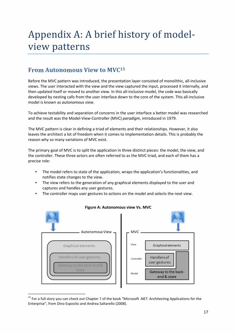
From Autonomous View to MVC15
Before the MVC pattern was introduced, the presentation layer consisted of monolithic, all-inclusive
views. The user interacted with the view and the view captured the input, processed it internally, and
then updated itself or moved to another view. In this all-inclusive model, the code was basically
developed by nesting calls from the user interface down to the core of the system. This all-inclusive
model is known as autonomous view.
To achieve testability and separation of concerns in the user interface a better model was researched
and the result was the Model-View-Controller (MVC) paradigm, introduced in 1979.
The MVC pattern is clear in defining a triad of elements and their relationships. However, it also
leaves the architect a lot of freedom when it comes to implementation details. This is probably the
reason why so many variations of MVC exist.
The primary goal of MVC is to split the application in three distinct pieces: the model, the view, and
the controller. These three actors are often referred to as the MVC triad, and each of them has a
precise role:
• The model refers to state of the application, wraps the application’s functionalities, and
notifies state changes to the view.
• The view refers to the generation of any graphical elements displayed to the user and
captures and handles any user gestures.
• The controller maps user gestures to actions on the model and selects the next view.
Figure A: Autonomous view Vs. MVC
15
For a full story you can check out Chapter 7 of the book “Microsoft .NET: Architecting Applications for the
Enterprise”, from Dino Esposito and Andrea Saltarello (2008).
18
The most obvious benefit of the MVC pattern is that it simplifies the testing of the presentation layer.
Moreover, by taking code out of the view, it also encourages code structuring and the creation of
logical layers, that is, you get “separation of concerns”.
Generality of MVC
Originally, MVC was conceived to be a pattern for building the whole application and not just the
presentation layer. Today, MVC is mostly about the presentation-view and the controller; and it is
used to get separation of concerns and testability in the presentation layer.
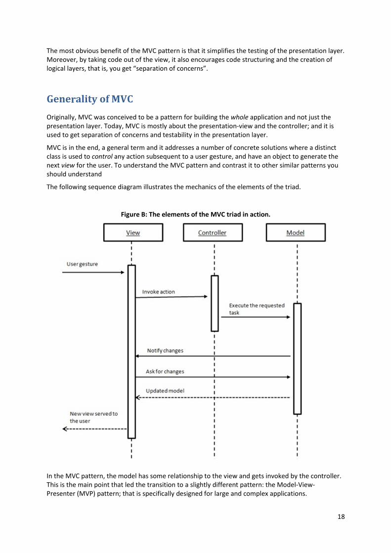
MVC is in the end, a general term and it addresses a number of concrete solutions where a distinct
class is used to control any action subsequent to a user gesture, and have an object to generate the
next view for the user. To understand the MVC pattern and contrast it to other similar patterns you
should understand
The following sequence diagram illustrates the mechanics of the elements of the triad.
Figure B: The elements of the MVC triad in action.
In the MVC pattern, the model has some relationship to the view and gets invoked by the controller.
This is the main point that led the transition to a slightly different pattern: the Model-View-
Presenter (MVP) pattern; that is specifically designed for large and complex applications.
19
The classic MVC pattern has two big drawbacks:
1. The model needs to communicate to the view changes of state, typically through
an Observer relationship.
2. The view has intimate knowledge of the model.
The view is refreshed when it gets a notification of changes in the model and it basically does that by
reading from the model any information it needs and displaying it through its UI elements. There is
no explicit contract that states which data the view needs precisely. As a result, the view needs to
have its own logic to select data from the big model and massage it to UI elements. This code can
hardly be taken out of the view. As a result, the view is not as passive as it should be. And also, the
view depends to some extent on the underlying platform or UI toolkit being used.
The controller should be just a Mediator between the view and the rest of the application. This is not
the case with plain MVC where its responsibilities are more distributed, and it has the power to
govern the rendering of the view while interacting with the model.
By defining a contract for the view, the presentation layer becomes even more testable, as the view
is now mockable and can be replaced with another view class implementing the same contract. In
this way:
1. The presentation logic gains independence from the UI platform and, for instance, the same
controller class can be reused.
2. The same controller class can work with different views of the same application.
The MVP pattern
MVP is a derivative of MVC aimed at providing a cleaner separation between the view, the model
and the controller. The creators of the MVP pattern took the MVC triad and separated the Model
from the View/Controller pair, which they called Presentation.
The three enhanced aspects of MVP over MVC are:
• The View doesn’t know Model;
• The Presenter ignores any UI technology behind the View;
• The View is mockable for testing purposes;
The figures below show a comparison between MVP and MVC:
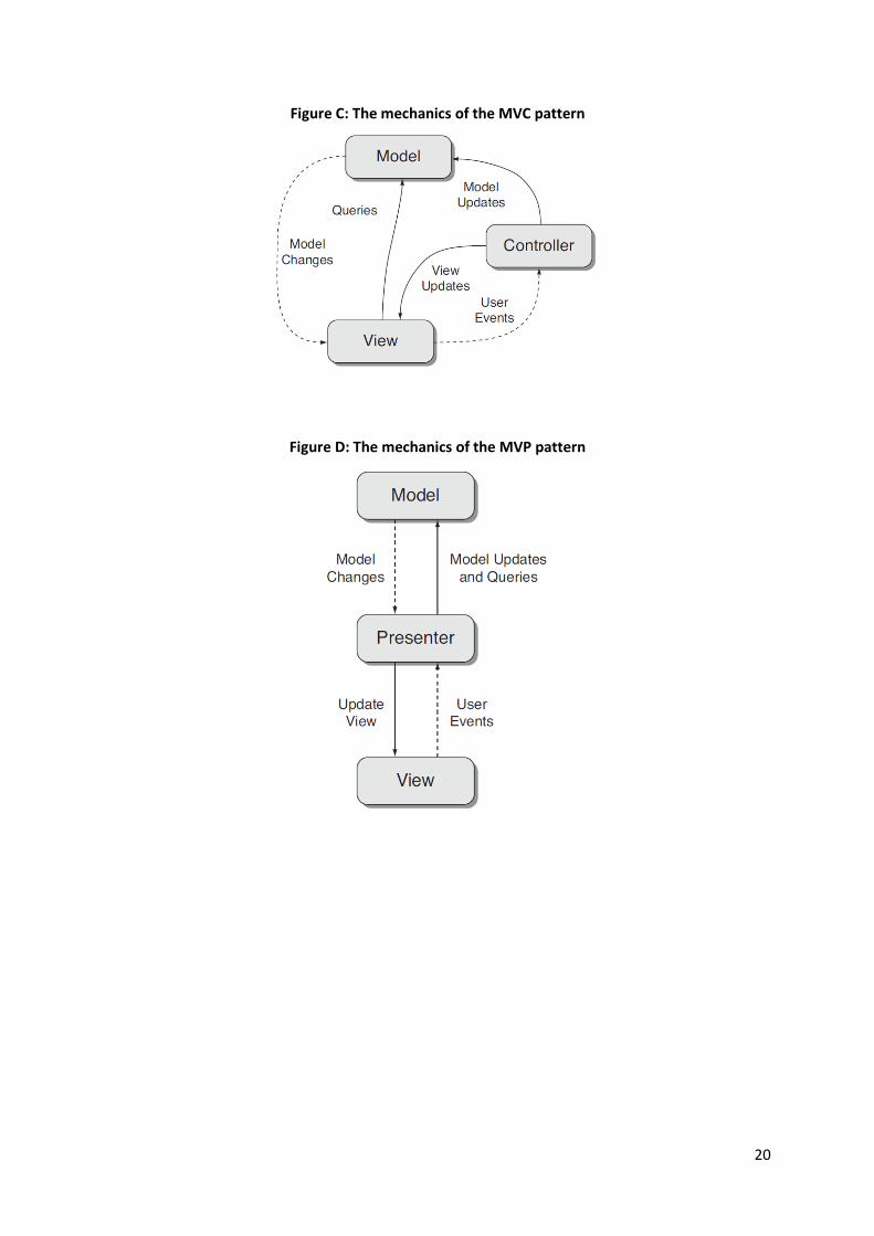
20
Figure C: The mechanics of the MVC pattern
Figure D: The mechanics of the MVP pattern
21
Appendix B: XSLT and XPath
Introduction
XSLT stands for Extensible Stylesheet Language Transformations and it is a declarative, XML-based
language used for the transformation of XML documents. Based on the contents of an existing
document, a new document is created without changing the original one. The new document may be
serialized (output) by the XSLT processor in standard XML syntax or in another format, such as HTML
or plain text.
Originally, XSLT was part of the W3C's Extensible Stylesheet Language (XSL) development effort of
1998–1999, a project that also produced XSL Formatting Objects and the XML Path Language, XPath.
Finally, XSLT 1.0 was published as a Recommendation by the W3C on 16 November 1999.
So, why XSL was necessary?
In the case of the Style Sheets for HTML language (CSS), HTML uses predefined tags, and the meaning
of each tag is well understood. If we take for example the case of the <table> tag in HTML, it defines a
table, and a browser knows how to display it.
Similarly, XSL is the Style Sheets for XML. But XML does not use predefined tags (we can use any tag-
names we like), and therefore the meaning of each tag is not well understood. Coming back to the
previous example, in an XML file, the <table> tag could mean anything, and so a browser does not
know how to display it. And this is where XSL comes into play, since it describes how the XML
document should be displayed!
XSL is much more than just a Style Sheet Language, and it consists of three parts:
• XSLT - a language for transforming XML documents
• XPath - a language for navigating in XML documents
• XSL-FO - a language for formatting XML documents
XSLT and XPath
XSLT relies upon the W3C's query language XPath (the XML Path Language) for identifying subsets of
the source document tree, as well as for performing calculations from the content of an XML
document (it provides a range of functions).
This reliance upon XPath adds a great deal of power and flexibility to XSLT.
22
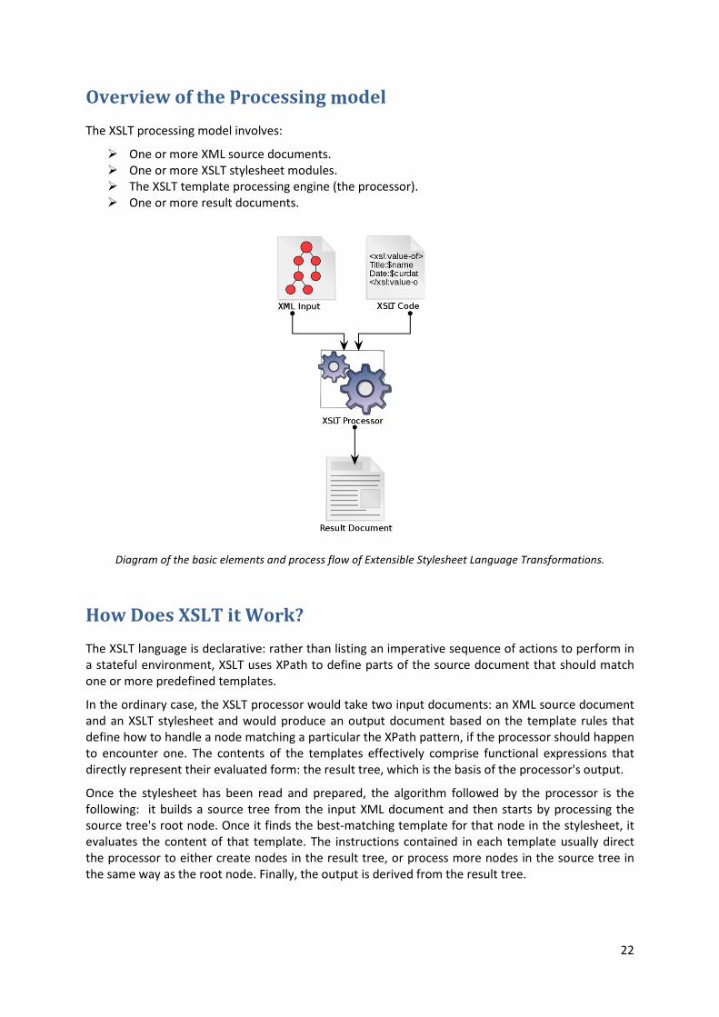
Overview of the processing model
The XSLT processing model involves:
� One or more XML source documents.
� One or more XSLT stylesheet modules.
� The XSLT template processing engine (the processor).
� One or more result documents.
Diagram of the basic elements and process flow of Extensible Stylesheet Language Transformations.
How Does XSLT it Work?
The XSLT language is declarative: rather than listing an imperative sequence of actions to perform in
a stateful environment, XSLT uses XPath to define parts of the source document that should match
one or more predefined templates.
In the ordinary case, the XSLT processor would take two input documents: an XML source document
and an XSLT stylesheet and would produce an output document based on the template rules that
define how to handle a node matching a particular the XPath pattern, if the processor should happen
to encounter one. The contents of the templates effectively comprise functional expressions that
directly represent their evaluated form: the result tree, which is the basis of the processor's output.
Once the stylesheet has been read and prepared, the algorithm followed by the processor is the
following: it builds a source tree from the input XML document and then starts by processing the
source tree's root node. Once it finds the best-matching template for that node in the stylesheet, it
evaluates the content of that template. The instructions contained in each template usually direct
the processor to either create nodes in the result tree, or process more nodes in the source tree in
the same way as the root node. Finally, the output is derived from the result tree.
23
Appendix C: Supplementary Figures
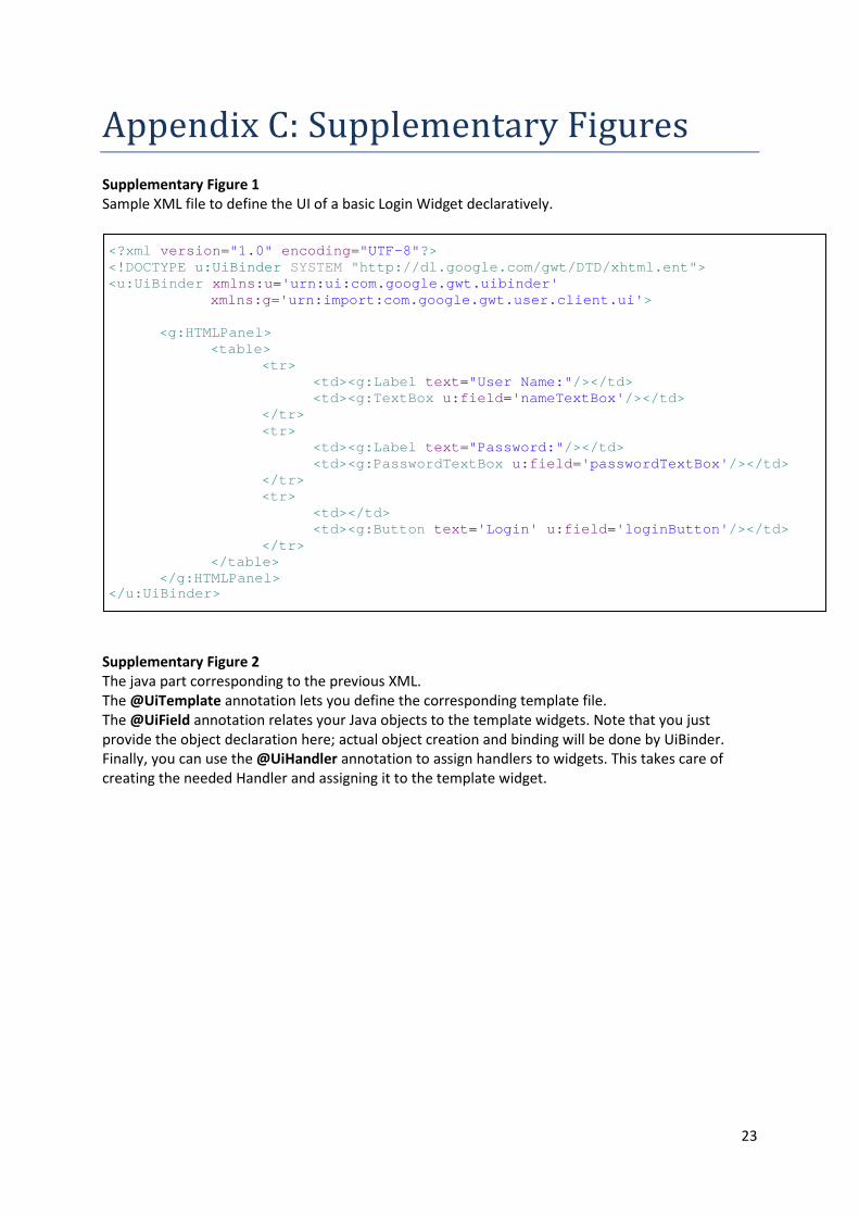
Supplementary Figure 1
Sample XML file to define the UI of a basic Login Widget declaratively.
Supplementary Figure 2
The java part corresponding to the previous XML.
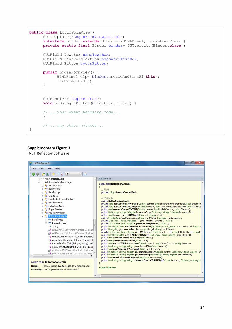
The @UiTemplate annotation lets you define the corresponding template file.
The @UiField annotation relates your Java objects to the template widgets. Note that you just
provide the object declaration here; actual object creation and binding will be done by UiBinder.
Finally, you can use the @UiHandler annotation to assign handlers to widgets. This takes care of
creating the needed Handler and assigning it to the template widget.
<?xml version ="1.0" encoding ="UTF-8" ?> <! DOCTYPE u:UiBinder SYSTEM "http://dl.google.com/gwt/DTD/xhtml.ent" > <u:UiBinder xmlns:u ='urn:ui:com.google.gwt.uibinder' xmlns:g ='urn:import:com.google.gwt.user.client.ui' > <g:HTMLPanel > <table > <tr > <td ><g:Label text ="User Name:" /></ td > <td ><g:TextBox u:field ='nameTextBox' /></ td > </ tr > <tr > <td ><g:Label text ="Password:" /></ td > <td ><g:PasswordTextBox u:field ='passwordTextBox' /></ td > </ tr > <tr > <td ></ td > <td ><g:Button text ='Login' u:field ='loginButton' /></ td > </ tr > </ table > </ g:HTMLPanel > </ u:UiBinder >
24
Supplementary Figure 3
.NET Reflector Software
public class LoginFormView { @UiTemplate( "LoginFormView.ui.xml" ) interface Binder extends UiBinder<HTMLPanel, LoginFormView> {} private static final Binder binder = GWT.create(Binder. class); @UiField TextBox nameTextBox ; @UiField PasswordTextBox passwordTextBox ; @UiField Button loginButton ; public LoginFormView() { HTMLPanel dlp= binder .createAndBindUi( this); initWidget(dlp); } @UiHandler( "loginButton" ) void uiOnLoginButton(ClickEvent event) { // ...your event handling code... } // ...any other methods... }
25
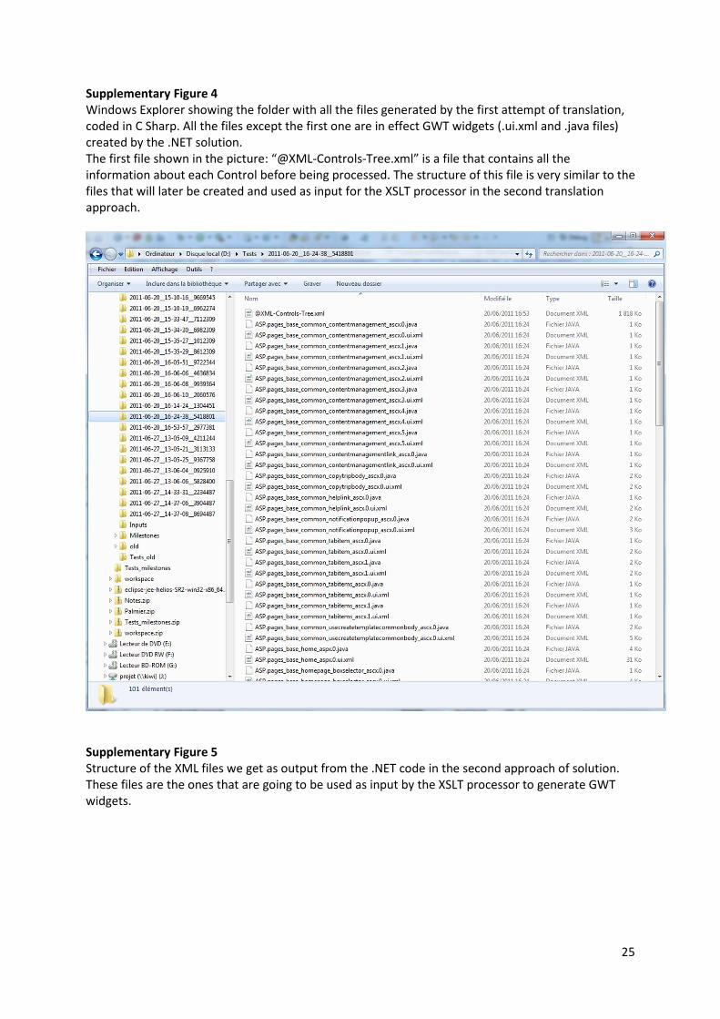
Supplementary Figure 4
Windows Explorer showing the folder with all the files generated by the first attempt of translation,
coded in C Sharp. All the files except the first one are in effect GWT widgets (.ui.xml and .java files)
created by the .NET solution.
The first file shown in the picture: “@XML-Controls-Tree.xml” is a file that contains all the
information about each Control before being processed. The structure of this file is very similar to the
files that will later be created and used as input for the XSLT processor in the second translation
approach.
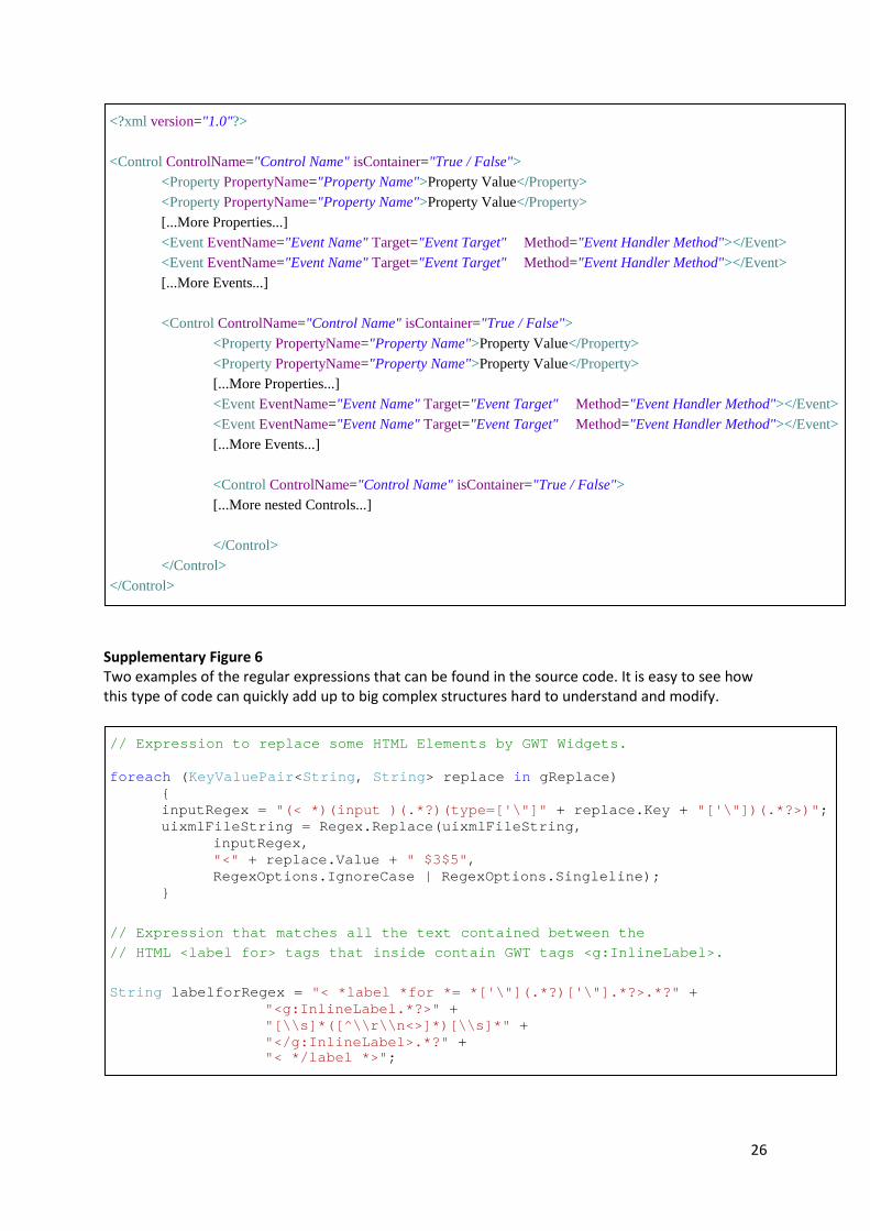
Supplementary Figure 5
Structure of the XML files we get as output from the .NET code in the second approach of solution.
These files are the ones that are going to be used as input by the XSLT processor to generate GWT
widgets.
26
Supplementary Figure 6
Two examples of the regular expressions that can be found in the source code. It is easy to see how
this type of code can quickly add up to big complex structures hard to understand and modify.
// Expression to replace some HTML Elements by GWT Widgets. foreach ( KeyValuePair <String , String > replace in gReplace)
{ inputRegex = "(< *)(input )(.*?)(type=['\"]" + replace.Key + "['\"])(.*?>)" ; uixmlFileString = Regex.Replace(uixmlFileString,
inputRegex, "<" + replace.Value + " $3$5" ,
RegexOptions.IgnoreCase | RegexOptions.Singleline) ; }
// Expression that matches all the text contained b etween the
// HTML <label for> tags that inside contain GWT ta gs <g:InlineLabel>.
String labelforRegex = "< *label *for *= *['\"](.*?)['\"].*?>.*?" + "<g:InlineLabel.*?>" +
"[\\s]*([^\\r\\n<>]*)[\\s]*" + "</g:InlineLabel>.*?" + "< */label *>" ;
<?xml version="1.0"?> <Control ControlName="Control Name" isContainer="True / False"> <Property PropertyName="Property Name">Property Value</Property> <Property PropertyName="Property Name">Property Value</Property> [...More Properties...] <Event EventName="Event Name" Target="Event Target" Method="Event Handler Method"></Event> <Event EventName="Event Name" Target="Event Target" Method="Event Handler Method"></Event> [...More Events...] <Control ControlName="Control Name" isContainer="True / False"> <Property PropertyName="Property Name">Property Value</Property> <Property PropertyName="Property Name">Property Value</Property> [...More Properties...] <Event EventName="Event Name" Target="Event Target" Method="Event Handler Method"></Event> <Event EventName="Event Name" Target="Event Target" Method="Event Handler Method"></Event> [...More Events...] <Control ControlName="Control Name" isContainer="True / False"> [...More nested Controls...] </Control> </Control> </Control>