Embed Size (px)
Citation preview

www.curiosis.com
Automated live cell imaging system
Celloger Nano™
Instruction manual

2
Developed and manufactured by CURIOSIS Inc. Email: [email protected] Website: www.curiosis.com
CURIOSIS Inc. 4F, 10 Teheran-ro 38-gil, Gangnam-gu, Seoul 06221, South Korea Tel: +82-2-508-5237 Fax: +82-2-508-5246
Copyright © 2021, by CURIOSIS Inc. All rights reserved. Published in Korea.

3
Table of contents Package contents 4
Device layout 5
Getting started 6
Pre-requirements 6
Installation 7
Software description 10
1) Celloger Nano APP 10
2) Celloger Nano Analysis APP 17
Operation overview 18
Create or open a project 19
Device connection 20
General operation 21
1. Preparation (cell/device preparation) 21
2. Cell monitoring and image setting 22
2.1. Location adjustment 22
2.2. Light intensity adjustment 26
3. Image analysis 27
3.1. Capture 27
3.2. Intensity 29
3.3. Ruler and manual count 30
4. Time-lapse 31
5. Process single image or time-lapse images 33
5.1 Import the original data taken by celloger nano 33
5.2 Slide show 34
5.3 Merge fl image 34
5.4 Estimate confluency (Coverage) 35
5.5 Make video 36
Safety instruction 37
General guidelines 37
Operating condition 37
Safety standards 38
Cleaning and maintenance 38
Trouble shooting 38
Product specifications 40
Ordering information 41
Appendix A. Connecting multiple devices 42
1. Installation 42
1.1 Device ip setup 42
1.2 Using a router 43
2. Operation 44
Appendix B. Alternative PC network setup 45

4
Package contents
Celloger NanoTM package includes the following items.
Item Quantity
Celloger Nano 1
Main Power Cable 1
POE Injector 1
Adapter 1
LAN Cable (5M, 4.8M) 2
USB memory 1
- Instruction Manual 1
- Celloger Nano App 1
- Celloger Nano Analysis App 1
When receiving the package,
• Check that all items listed above are included in your package.
• Examine the device carefully for any damage during shipping.
• Contact your local distributor or [email protected] if any items are missing or damaged.
• Any loss or damage claims must be filed with the carrier.

5
Device layout Front-left side
POE Injector

6
Getting started
Pre-requirements
Installation location For normal and stable operation of the device, the following environmental conditions should be satisfied.
Keep the device at temperature between 10 ~ 40 °C.
It is not recommended to operate the device at low temperature (Below 10 °C).
In those conditions, warm up the device for over 10 minutes.
Relative humidity between 0 ~ 95 %.
Install it on a flat and level surface.
Place at dust- or other airborne particles-free area.
During operation, place around 10cm away from the surroundings for proper air flow of the cooling fan.
During operation inside incubator, do not place close to the incubator door.
Do not put any heavy materials on top of the device.
Do not place it together with vibrating equipment.
Upon using multiple equipment, there should be a proper clearance among equipment.
PC specifications (Refer to page 40)
Celloger Nano software can be used on PCs with Window 10.
Large capacity hard drive is necessary to save images from Timelapse. If the capacity is not enough,
scanning will not function properly.
For the ease of use, it is recommended to use a monitor with resolution of 1920 x 1080.
LAN port is required to connect the equipment to PC using LAN cable. If there is no LAN port, LAN cable
adapter should be prepared.

7
Installation 1. Prepare a computer that meets the specifications and place it near the incubator. (PC specifications
p.40)
2. Take the equipment out of package and put it on a flat desk.
3. Connect two LAN cables and power cable to the POE injector.
Connect one LAN cable to the equipment (yellow) and another LAN cable to the PC (white).
4. Connect the power cable to an outlet.
5. Turn on the power by pressing the power switch located next to the power cable port.
6. Perform the PC network setting (changing PC IP address) as follows to connect the PC with the
equipment. Alternative method to set PC network within the Celloger Nano App can be found in
Appendix B (p.45)
6.1 Click the “Start” button or the “Window” icon.
6.2 Click the “Setting” button.
6.3 Click “Network and Internet” in Control Panel.
6.4 Click the “Ethernet” button.
6.5 Click “Network and Sharing Center”.
6.6 Click “Change adapter settings” on the left-side menu.
6.7 Select “Ethernet” (This name can vary according to PC.) button and right-click the mouse and click
“Properties” in the window that appears.
6.8 Select “Internet Protocol Version 4 (TCP/IPv4)” and click “Properties”.
6.9 Select “Use the following IP address” and enter IP address (192.168.2.XX*) and Subnet mask
(255.255.255.0) in the blank fields
Note. Fill 2~254 except 10 in XX* field.
- The PC IP address should be set differently from the
device IP address or network adapter such as a
router. The default device IP is 192.168. 2. 10 and to
set up the PC IP address, enter 192.168.2.XX (in XX
field, input 2~254 except 10).
- This IP setting guideline may not be applicable to
some PC depending on the PC network environment.
In case of connection failure, contact us via
[email protected] or local distributor.
6.10 Click OK, then network configuration is
completed.
Power cable
LAN cable into device
LAN cable to PC

8
7. To start Celloger Nano App, first, connect the USB drive provided with the device into the PC, then
copy APP folder to the PC and execute “Celloger Nano App.exe” in the APP folder.
<Image Descriptions of PC network setting>
①
②
③
④ ⑤
⑥

9
⑦
⑧ ⑨

10
Software description
Celloger Nano provides two software: Celloger Nano App and Analysis App. Celloger Nano App is a program
for actual operation of Celloger Nano device that includes real-time monitoring and time-lapse imaging
function. Celloger Nano Analysis App is a program for analyzing or post-processing the images obtained from
Celloger Nano and it operates even without the device connection.
1) Celloger Nano APP
Upon opening Celloger Nano App and completing pre-setup (Refer to p.19~20), the following main page is
displayed.
① Menu Bar [ File ]
✓ Open Project : Import a previously saved project.
✓ Save Project : Save the settings on the current project.
✓ Save Project As… : Create a new project with the current settings (Light
intensity, Focus position, Schedule, etc.).
✓ Save Image As… : Save the Preview image.
① ②
③
④
⑥
⑤

11
[ Tool ]
[ Device ]
[ Help ]
② Toolbox
[ Preview ]
: Streaming on/off on the Display. The live image is shown based on the selected channel such
as bright- field (Hereafter ”BF”), green fluorescence (Hereafter “FL green”) and red fluorescence (Hereafter
“FL red”) at the “Light Source Control”.
✓ : Streaming on
➢ Visibility : Show/hide features displaying image information such as
histogram.
✓ Histogram (p.29) : Show/hide intensity histogram of an image.
✓ Intensity (p.29) : Show/hide point and mean intensity of an image.
✓ Manual Counting : Show/hide “Manual Counting” function.
✓ Scale Bar : Show/hide a scale bar.
✓ Center Mark : Show/hide a cross-shaped feature at the center of the
display for reference.
✓ Connect : Connect a new device or change the connection to another device.
✓ Reboot : Reboot the connected device.
✓ IPAddress : Change the IP address of the connected device.
✓ Status : Display the status of connected device.
✓ Parameter : Display the values set for the connected device. Certain
parameters can only be manipulated by an authorized person.
➢ Manual Counting (p.31) : Count the points clicked by user.
✓ Count : Add a point for counting.
✓ Remove : Delete a clicked point.
✓ Clear : Delete all points.
➢ Reset Layout (p.13) : Return to User Interface before change
➢ Preferences : Set “AutoFocus” (Refer to p.24), merge layer (Refer to
p.28), and appearance (change the color and font size of the feature).
✓ About CellogerApp: Display App information.
✓ : Streaming off

12
[ File ]
: Save the image on the Display.
[ Zoom & Pan ]
✓ : Zoom in (Digital zoom)
✓ : Zoom out (Digital zoom)
✓ : Pan (Drag the display in Zoom-in status)
✓ : Return the zoomed image or relocated image to its original state at once.
[ Measure ]
Measure the length between the two clicked points.
✓ : Measure the distance between two selected points.
✓ : Measure the distance between two selected points on horizontally.
✓ : Measure the distance between two selected points on vertically.
[ Layer ]
✓ : Merged layer (Merge activated layers of BF and FL image).
Note. Once activating “merged layer”, the displayed image is an image processed by setting
“Opacity” and “Threshold” in the “Preferences” (Refer to p. 28).
✓ : BF image layer
✓ : FL (FL Green/FL Red) image layer
✓ : Features [Ruler(Measure), scale bar, manual count, etc.] layer
[ Device control ]
✓ : Execute autofocusing in streaming on state according to autofocusing setting (Refer to p.24).
✓ : Turn on the white light in the LED status indicator of the connected device.
✓ : Fan on/off
③ Display Show real-time image upon activating Preview or the last captured image during time-lapse.

13
④ Light Source Control
The tabs in “Light Source Control” are composed of BF, FL green and FL red. The configuration of tabs are
set depending on the light options of Celloger Nano.
✓ LampPower (%) : Control lamp (Illuminator) power (0~100%).
✓ Exposure (Second): The duration of exposure of cells to light (0.010~2.000 second). Be careful as
photobleaching occurs when exposure value is high.
✓ Gain : The amount of signal amplification (1.0~10.0) during the process of changing photon data to
digital data. This is a parameter associated to the contrast of image. Be careful as noise becomes
higher when gain value is high.
✓ Offset : (Black level) Brightness of a dark range of image. Be careful as contrast becomes low when
offset value is high.
⑤ Stage & Time-lapse Control
Window can be separately floated so that it can fit on the monitor. It is possible to change the window by
pressing (Context Menu) for floating or hiding. It can convert to AutoHide/Dockable immediately by
clicking . The Layout is automatically saved upon terminating the program. To go back to original state,
press “Reset Layout” in the “Tool” before closing the program.
Note. When the window disappears, delete “LayoutCNN.xml” in the program folder to go back to default
state after closing the program.
[ Z Stage control ]
A. Current Z stage coordinate
B. Upon pressing “Go” after entering the desired coordinate in the box, the stage is moved according
to the set coordinates. Upon pressing , current coordinate is entered in the Box.
C. Distance moved upon pressing Jog button (D) once (Hereinafter referred to as “step distance”).
: Step distance unit : Step distance
A C
B D

14
D. Jog button
: Move Z stage up. [Z coordinate + step distance]
: Stop the stage on the move.
: Move Z stage down. [Z coordinate - step distance]
[ Focus ]
Select the channel used for time lapse imaging and select the focus position (Z coordinate) for each channel.
✓ Imaging Channel : Channel used for time-lapse imaging. BF is always checked.
✓ Ref. Pos. (Reference position)/ Offset
➢ Reference position : Position of BF channel for time-lapse.
A. : Upon clicking, the current coordinate is entered on the box next to it.
B. : The location of z axis of BF channel when Auto Focus function is off (None) or median
coordinate when Auto Focus is on (FirstCycle or EveryCycle).
C. : Upon clicking, location moves according to coordinates shown on the left box.
➢ Offset from BF reference position : Position of FL channel for time-lapse.
A. : Upon clicking, the current coordinate is entered on the box next to it.
B. : The location of z axis of FL channel captured while performing time lapse. The value
shown is the difference from the location of Z axis captured in the BF channel(B). To capture the
FL channel on the same coordinates of BF channel, enter 0.
C. : Upon clicking this button, move to coordinates shown on the left box.
A B C D E F

15
✓ Auto Focus
[ Schedule ]
Set the schedule for time-lapse imaging.
Time except for End Date and Total Cycle can be selected. Click using the mouse, turn the mouse wheel or
click right arrow or calendar for selection.
✓ Interval time : Interval between scanning cycles
✓ Total Running Time : Time-lapse execution period
✓ Start Date : Time lapse start time
(If the time set is past time, the time changes automatically to the time when the button is pressed upon
pressing “Start”.)
✓ End date : Time lapse complete time
(It is determined by Total Running Time and Start Date, and the user cannot directly change the value.)
✓ Total Cycle Expected :The number of scans during time lapse period
(It is determined by Interval time and Total Running Time, and the user cannot directly change the value.)
Note. The total cycle expected is calculated by simply dividing the total running time by interval time and
does not consider the data processing time. Therefore, the expected total cycle could be different from
the actual scanning cycles.
➢ None : During time-lapse imaging, it does not execute autofocusing function and
captures based on the entered coordinates (Ref. Pos./Offset B)
➢ FirstCycle : During time-lapse imaging, the autofocusing function is executed only
for the first cycle and the capturing for other cycles is done on the z coordinates
designated in the first cycle.
➢ EveryCycle : During time-lapse imaging, execute autofocusing function every
cycle.

16
[ Time lapse panel ]
A. The time elapsed (“Elapsed”) and progress rate (%) during the total time lapse running time. Count
means the number of times scanning occurred. Upon clicking Start, scanning begins and this refers
to count 1. (Count = Cycle count + 1)
B. The progress rate (%) within a cycle and remaining time until the next cycle (“Remaining”). Index
shows the number of images taken within a cycle (With Celloger Nano, Index is always 0).
C. Current date and time.
D. Upon clicking “Start”, scanning starts based on the schedule.
⑥ Connection status
It shows device connection status, and information on connected devices.
A. IP address of connected device.
B. Description of connected device (Can be changed in “Device”-> “Parameter”).
C. Serial number of connected device.
D. Firmware version of connected device.
Note. If device is not connected, shows up. Click “Device”-> “connection”
for reconnection. If the connection window does not show the device icon, Refer to p.20.
A B
C
D
A B C D

17
2) Celloger Nano Analysis APP
Upon opening Celloger Nano Analysis App and selecting ‘Config file’, the following main page is displayed
① Menu bar
It is managed by “config file” instead of a project.
Other menus are the same as those of Celloger Nano App.
② Toolbox
: Mask the area recognized as confluency (Possible to use after confluency analysis). All other tools
and functions are the same as those of Celloger Nano App.
③ Display
Display the image selected from Image Analysis control list (⑤). The image is displayed based on the
activated channel that can be selected in “Light source control” (④). Upon completing analysis, coverage
mask is shown and functions such as measure (Ruler), Intensity (point), manual counting can be
performed on the screen.
①
②
③
④
①
②
③
④
⑤

18
④ Light Source Control
Display the light source settings of Celloger Nano App and it cannot be changed.
⑤ Image Analysis Control
Upon importing a folder, file list is displayed.
Upon selecting the file, the image is shown on
Display.
It is possible to analyze images or make video.
(Refer to p.33)
Analyze: Calculate the confluence of the files
checked on the list. Analyze the image of
selected light channels on the right (Refer to
p.35).
Record: Make video (Refer to p.36).
Play: Show the images in the list in order (Refer
to slideshow p.34).
Stop: Stop playing.
Operation overview

19
Create or open a project
✓ With Celloger Nano, the settings can be managed by the project file (“.cgnproj” file format). Setting values
(Light intensity, Focus position, Schedule, file storage location, etc.) are saved in the project.
✓ Upon executing App, popup screen for project selection is displayed.
✓ Create a new project or open and existing one. You can start a program with default project by clicking
“Continue without configuration”.
✓ Upon selecting Create Project, popup window that requires the selection of project name and storage
location shows up. You can start the program after entering required information and press OK. The
storage location of the project is the address of default program file and cancel “Use default location” and
enter address to change the storage location.
Import the project saved in the
past.
Create new Project.
Start the program without
Customizing a Project. In this case,
a default project “Experiment” is
executed.

20
Device connection Icon of devices connected by LAN cable is shown. To connect the device, select the icon and press “Connect”.
Upon completing the connection, the color of LED status indicator changes from red to green.
Note. If the icon is not shown, check the following steps and take appropriate actions.
Case 1. PC IP setting is not completed properly.
Reset the PC IP. If the PC IP, Device IP, Router IP are the same, connection fails (PC IP setting p.7 step 6).
Case 2. LAN or power cable is not connected properly (LED status indicator is turned off).
Check all cable connection status and POE injector power (Installation p.7 step 3 to 5).
Case 3. Separate LAN Adaptor is used.
Press the arrow on the right to select the
adaptor to which the device is connected.
Case 4. When using multiple devices in one PC, each device has the same IP.
Initially, devices are released with the same IP. When using the device for the first time, it is necessary to reset the IP address.
(Appendix. A. Device IP setting p.42)

21
General Operation 1. Preparation (Cell/device preparation)
The cell preparation method is different depending on the type of assay. The method below is a general
process recommended for the monitoring of cells.
① Before culturing the cell, place Celloger Nano in incubator for prewarming.
Note. Install the system as far as possible from the incubator door and place the device around 10 cm
away from the surroundings for proper air flow of rear cooling fan. If you want to find and adjust the
specific area for scanning, carefully move into incubator with cells after positioning the plate.
(Positioning step p.22)
② Prepare pre-warmed medium and cells on a plate.
③ Discard the medium on vessel and wash the cells with PBS buffer.
④ Discard PBS buffer and treat trypsin-EDTA solution to detach the cell from vessel.
⑤ Incubate for a few minutes and check cell detachment by Celloger Nano or microscopy.
⑥ Remove cell and trypsin-EDTA to conical tube and add fresh medium to neutralize the Trypsin reagent.
⑦ Centrifuge the suspension cells on conical tube.
⑧ Discard the supernatant and add fresh medium into cells.
⑨ Gently pipette the cell several times.
⑩ Transfer the appropriate amount of cells into new vessel and dilute the cell concentration by fresh
medium.
⑪ Cover the plate with a lid and gently shake the plate to spread the cells evenly.
Note. Before covering the plate, warm the lid by slightly passing the lid over fire of alcohol lamp to
prevent condensation. This step is not necessary, but it will prevent trapping the condensation on a
lid.
⑫ Place the plate on Celloger Nano.
Note. Both plate and device should be prewarmed for 30 minutes prior to timelapse imaging to prevent
condensation.

22
2. Cell monitoring and image setting
2.1. Location adjustment
Celloger Nano has mechanical X/Y stage and motorized Z stage.
1) Adjust X/Y position
XY stage of Celloger Nano uses X/Y stage controller (Knob) to move X/Y axis by +/-6mm
respectively. To adjust further, the vessel must be manually moved. In order to designate the scan
point, first, move the vessel by hand to see the desired location in Preview state, and then adjust
the X/Y location using X/Y stage controller.
① Press Preview for streaming while BF is
selected in the “Light Source Control”.
② Check the Display while moving the vessel (If it is too dark or too bright
to see the cells, perform “2.2 Quantity of Light Adjustment” first).
③ If the target cells become visible, use X/Y stage controller for precise
adjustment.
2) Set Z position
➢ Manual adjustment
In the Preview state (“BF” tab selected on “Light Source Control”) select the “step” in Z stage control
as X1mm and press “Jog” to move to the point where cells are visible. Conduct precise adjustment
gradually by reducing the “step”. Selecting clear focal position is one of the major factors that
influence the accuracy of analysis. Therefore, analysis can be precisely conducted when cells are
clearly distinguishable from background and the shape of cells are clearly visible.
Note. Celloger Nano’s Z stage absolute coordinate error is 0.001mm.

23
Step X1mm manipulation
(Z : 2.000)
Step X 100um manipulation
(Z : 2.100)
Step X 10um manipulation
(Z : 2.060)
Step X 1um manipulation
(Z : 2.055)

24
Upon finding the best focal point for scanning, designate the location by pressing in Focus.
Note. Since the focus of the FL channel may be different from that of the BF, it is recommended to set
the focus position individually. For Z positioning of the FL channel, check the Display while FL channel
is selected in Light Source Control, and move the jog to find a clear point like BF.
➢ Auto focusing
Autofocus function of Celloger Nano works by selecting clear focal point after screening the area up
and down the location. Therefore, it is necessary to have the focus location within the designated
range in Autofocus parameter for more successful autofocusing. Therefore, set Z position roughly
(manually) and use the Autofocusing function.
<Example of setting Autofocusing for Time-lapse>
1. Move the focal plane using Jog
(Z:2.100)
2. Open Preferences in the Tool menu.
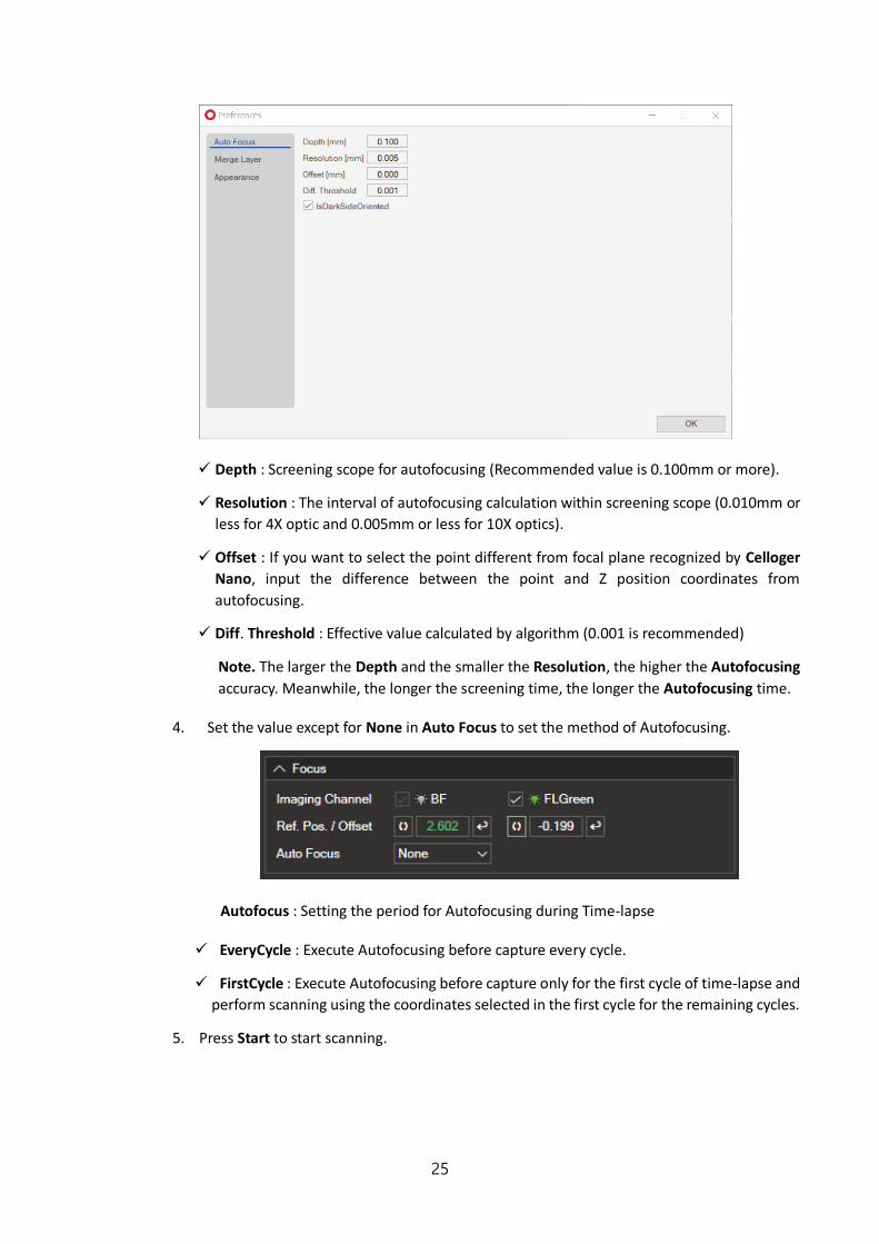
3. Designate parameter (Depth, Resolution, Cycle) in the “Auto Focus” tab and press
OK.
25
✓ Depth : Screening scope for autofocusing (Recommended value is 0.100mm or more).
✓ Resolution : The interval of autofocusing calculation within screening scope (0.010mm or
less for 4X optic and 0.005mm or less for 10X optics).
✓ Offset : If you want to select the point different from focal plane recognized by Celloger
Nano, input the difference between the point and Z position coordinates from
autofocusing.
✓ Diff. Threshold : Effective value calculated by algorithm (0.001 is recommended)
Note. The larger the Depth and the smaller the Resolution, the higher the Autofocusing
accuracy. Meanwhile, the longer the screening time, the longer the Autofocusing time.
4. Set the value except for None in Auto Focus to set the method of Autofocusing.
Autofocus : Setting the period for Autofocusing during Time-lapse
✓ EveryCycle : Execute Autofocusing before capture every cycle.
✓ FirstCycle : Execute Autofocusing before capture only for the first cycle of time-lapse and
perform scanning using the coordinates selected in the first cycle for the remaining cycles.
5. Press Start to start scanning.

26
2.2. Light intensity adjustment
Light source option for Celloger Nano is displayed on the upper tab (Light Source Control in Celloger
Nano App). Select the desired light source to adjust and change the parameter. It is automatically saved.
Brightness is one of the important factors that has an impact on analysis accuracy. It is important to set
the appropriate brightness to distinguish cells from background.
Figure. Shows the Light source panel in the App connected to Green FL Celloger Nano
1) Select BF (Bright Field), press and check Display in streaming on( ) state.
2) Adjust the brightness by changing LampPower, Exposure, Gain, Offset.
Note. High Gain value causes noise. Therefore, adjust LampPower, Exposure, and Offset first.
However, if brightness is not enough after the adjustment, change the Gain value. It is
recommendable to run lamp power under 70 when performing time-lapse (FL).
Note. When analyzing the cell confluency, image intensity mean should be at least 120. (How to
check the image intensity mean, refer to page 29)
2.3. Z stacking 1) Manual Z stacking
① By using jog, find the position to start “Stacking”.
② Save the stacking unit in the Step. Ex) Step setting for stacking by 10um
③ Press Jog once and save it by pressing .
④ Repeat step ③ until it reaches the desired range of stacking.
⑤ Press Jog once and save it by pressing .
⑥ Repeat step ⑤ until it reaches the desired range of stacking.
2) Automated Z-stacking
The function is being developed.

27
3. Image Analysis
3.1. Capture
Icon ( ) in the Toolbox captures the image on Display.
1) An image with features
It is possible to generate and manipulate the desired features, show it on Display and save it as it is.
To obtain image without features, press (Feature layer) for deactivation and then press .
2) BF or FL channel image
Press the desired tab of the channel in Light Source Control to show the image on Display through
preview and press .
<BF channel image> <FL channel image>

28
3) Merge image
Press (Merge layers) for activation ( )merged image is shown on the Display.
Adjusted image as follows can be obtained upon changing Merge Layers setting (Opacity and
Threshold) in the Preferences of Tool menu.
* FL image Thresholding
Celloger Nano conducts thresholding for FL channel image based on intensity and merge it with BR
image. There are two methods for intensity thresholding.
Method 1) Global thresholding: Thresholding is executed based on the overall intensity of the image.
Adjust a parameter of Threshold while looking at the mask of an image after unchecking
the Adaptive algorithm box.
Method 2) Local adaptive thresholding: Divide the image into local areas and thresholding is
conducted by comparing relative intensity among areas. Adjust parameters of the Kernel
size and offset while looking at the mask of the image after checking the Adaptive
algorithm box. (Kernel size indicates size of “local” and Offset indicates the relative offset
of the threshold of the local area.)
Threshold adjustment of FL
Green
29
Note: When the Fluorescence areas are distorted or clustered in one place, Global thresholding
function is recommended; and when the Fluorescence areas are evenly distributed, the Local adaptive
thresholding function is recommended.
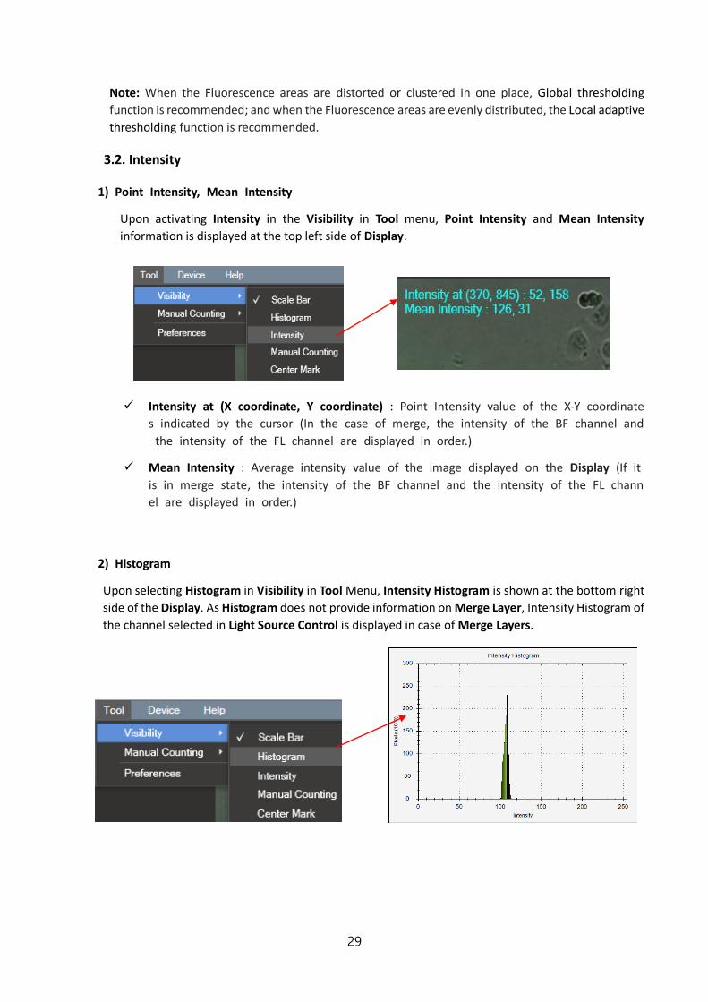
3.2. Intensity
1) Point Intensity, Mean Intensity
Upon activating Intensity in the Visibility in Tool menu, Point Intensity and Mean Intensity
information is displayed at the top left side of Display.
✓ Intensity at (X coordinate, Y coordinate) : Point Intensity value of the X-Y coordinate
s indicated by the cursor (In the case of merge, the intensity of the BF channel and
the intensity of the FL channel are displayed in order.)
✓ Mean Intensity : Average intensity value of the image displayed on the Display (If it
is in merge state, the intensity of the BF channel and the intensity of the FL chann
el are displayed in order.)
2) Histogram
Upon selecting Histogram in Visibility in Tool Menu, Intensity Histogram is shown at the bottom right
side of the Display. As Histogram does not provide information on Merge Layer, Intensity Histogram of
the channel selected in Light Source Control is displayed in case of Merge Layers.

30
3.3. Ruler and manual count
1) Ruler
In Measures, select either (Free) or (Horizontal) or (Vertical) directions and select the
desired area from point to point.
The number on the line is the length measurement (um).
Note : The font size of the number can be changed in
“Appearance” in the Tool menu.

31
2) Manual count
Select Count in the Manual Counting in the Tool menu and click the desired area to count with cursor,
clicked area is checked and the counted number is shown in Counting Result.
To delete part of the result, press Remove and click the items to be deleted. To delete all press Clear.
To hide them without removing all data, deactivate them by pressing Manual Counting activated in
Visibility of Tool menu.
Note : It is possible to change the font size of the number in the menu: “Tool”-> “Appearance”.
4. Time-lapse
① Select scan position and adjust light intensity (p.22 and p.26).
② Select the channel for scanning and adjust focus points for each channel. (p.22)
③ Set the Schedule.

32
④ Set Interval Time, Total Running Time, and Start Date. For an immediate start, leave the
Start Date as is.
Note. If the Start Date is set as past, it is updated automatically to the present time.
To change the schedule, put the cursor on the desired area to change and rotate the mouse wheel. It is
also possible to change the value by clicking up/down button on the right.
Upon clicking icon, calendar pops up enabling modification of date intuitively.
⑤ Upon pressing Start, scanning begins.
Note. The LED status indicator lights up blue while performing timelapse.
⑥ When Total progress bar becomes 100%, open the folder with the project name to check
the image, make video using Celloger Nano Analysis App or conduct additional analysis.
Note. The default image is in Tiff format and raw image of each channel is stacked. Stack image can
be checked with window default image viewer. (Program “Window Photo Viewer”)
<Calendar>
Popup>
<BF image> <FL image>

33
5. Process single image or time-lapse images
It is possible to conduct confluency analysis and make videos in the Celloger Analysis App using time-
lapse images taken by Celloger Nano. In addition, intensity measurement, length measurement and
manual counting are available in the Celloger Nano Analysis App and the methods are same as Celloger
Nano App.
* Config file: File for saving and managing parameters set in the Preference of the Tool menu (Pops up
when Celloger Analysis App starts)
5.1 Import the original data taken by Celloger Nano
Celloger Analysis App can only import the original data taken by Celloger Nano App.
* Open the folder (Timelapse)
*Open the image file.
Note. Folders can be dragged.
Select the timelapse folder taken
by Celloger Nano.
Drag the image file.

34
Note. The file location, address, and file name should only be composed of English alphabets,
numbers and some special symbols to import the file correctly in Celloger Nano App. If it fails to
import the file, check whether the file location address is written in languages other than English.
5.2 Slide show
① Open the Timelapse folder.
② Select the light channel or press (Merge layer activation).
③ Press .
Note. In order to change the speed, change the FPS in the preferences of the Tool.
Note. FPS is a parameter indicating the
speed of slideshow and video. However, the
speed of slideshow and video could be
different even with the same FPS.
5.3 Merge FL image
The same as Celloger Nano App. (Refer to p.28)

35
5.4 Estimate confluency (Coverage)
① Open the file and images captured with Celloger Nano.
② Press (To analyze certain images from the retrieved file, use check function on the left)
Note. Upon selecting right Icon (Green FL device) or (Red FL device) the coverage ratio of
the fluorescence area is calculated. At this point, coverage is calculated after thresholding according
to merge parameter. Therefore, to accurately calculate the coverage of fluorescence area, adjust the
appropriate thresholding parameters (refer to p.28) before executing the coverage analysis.
③ Graph, measured values and confluency mask are displayed. Upon selected an file from the list, image
and mask are shown.
④ In order to adjust Confluency masking color or transparency, change the parameter in merge layer
(Preference in Tool menu).
If you don’t want to see masking, press in the toolbox for deactivation.

36
5.5 Make video
① Open the Timelapse folder.
② Select the light channel or merge (Merge layer activation ).
③ Create video by pressing (The video is saved where the timelapse folder is located).
④ Open the file for confirmation.
Note. In order to change the speed, change the parameter in the Preferences of the Tool menu.
(Recommended value: 5~13)
Note. FPS is a parameter indicating the speed of slideshow and video. However, the speed of
slideshow and video could be different even with the same FPS.

37
Safety Instruction
* Read all instructions before use.
General guidelines
Install the device on a rigid and level places.
Operate the device in conditions described in the operating condition.
Use only the components provided and authorized by Curiosis Inc.
Ensure the input voltage matches with the device’s power supply voltage.
Check if the power cable is properly grounded to avoid potential electric shock.
Disconnect the power cable when abnormalities occur.
Wait about 2-3 minutes for the device to boot.
Do not insert any metallic objects into the device through bottom and side air vent to avoid electrical shock causing personal injury or device damage.
Place the device around 10 cm away from the surroundings for proper air-cooling.
Do not disassemble the device in any event. Contact your local distributor to arrange for service in case of malfunctioning. Malfunctions caused by disassembling of devices, external shock or internal contamination, the warranty is not provided even though warranty period remains.
Operate the device carefully as described in this manual.
Do not bend the cable excessively.
There is a risk of damage when stage knob is used with excessive force.
Use authorized accessories only.
Operating condition
Operating power 100~240 VAC
Electrical input 24 VDC, 2.5 A
Frequency ~50/60Hz
Operating temperature 10~40℃
Relative humidity 0~95%
Installation site Indoor use only

38
Safety standards
European standards US standards
Cleaning and Maintenance
When cleaning optical elements, use only a damp cloth to avoid scratching soft lens coatings. Do not
clean lenses with organic solvents.
Lightly wipe working surfaces of the Celloger Nano with soft cloth dampened with 70 % ethanol or
hydrogen peroxide (H2O2). Do not pour or spray liquids directly anywhere on the instrument.
If liquid spills on the instrument, turn off the power and wipe dry immediately.
Make sure that liquid or foreign matters do not enter fan holes or lens holes.
In case of storage at a room temperature after taking it out of the incubator, store it in a dry and well-
ventilated place.
Never disassemble the instrument yourself. Do not remove any covers or parts that require use of tool
to obtain access to moving parts.
Operators must be trained before being allowed to perform the hazardous operation.
Unauthorized repairs may damage the instrument or alter its functionality, which may void your warranty. Contact your local distributor to arrange for service.
Do not place the POE injector inside in the incubator.
Do not block the fan hole of the device.
Trouble Shooting
Installation
Device does not power up ✓ Check power source or contact your distributor. ✓ Replace power cable if it is in poor condition.
Cannot connect with Celloger Nano device ✓ Make sure the device is connected to the computer. ✓ Unplug and re-connect all cables. Restart the Celloger Nano App.
Focus
Focus is irregular ✓ Make sure the sample thickness is uniform.

39
Autofocusing does not work properly ✓ Before using Auto Focus, partially set the focus manually. ✓ Change the Auto Focus setting.
Image monitoring
Image display is dark ✓ Click the Preview button. ✓ Place sample on the center of objective lens.
Image is not clear ✓ Carefully wipe off the objective lens with cotton swab. ✓ Eliminate any dust on culture dish and LED lamp. ✓ Remove any condensation on the lid of the culture dish.
Problem in saving files ✓ Check the unused volume of the hard disk.
Time-lapse images become dark and bright ✓ Warm up the device 30 minutes before start monitoring. ✓ Eliminate dust on culture dish. ✓ Check for and remove any condensation on the lid of the culture dish. (In order to prevent condensation
from occurring, it is better to warm up the plate or dish lid slightly when preparing the sample). ✓ To prevent any problem such as shaking of culture dish or inflowing light, pay special attention when
you open or close incubator door during monitoring. ✓ Do not install the device close to the front/ door area of the incubator. Given that the incubator has high
temperature and humidity, the area that comes in frequent contact with cool outside air may have condensation. It is recommended to install it inside the incubator as much as possible.
Data
Cannot play the video ✓ Video can be made only for time-lapse images obtained from Celloger Nano App program.
Cannot analyze the confluency ✓ Check if the images are obtained from Celloger Nano App; Analysis can be performed only with the
images obtained from Celloger Nano App. ✓ Before analyzing, check if the focus is clear. ✓ Conduct FL merge, set appropriate thresholding parameter and use coverage analysis to calculate the
coverage of fluorescence.

40
Product specifications Dimension 211 x 146 x188 mm
Weight 3.2kg / 7.0lb
Objective Lens 4X / 10X
Fluorescence Green : Excitation (480/30x) / Emission (535/40m)
Red: Excitation (540/25x) / Emission (575lp)
Light source LED
Camera 1.25MP CMOS
Stage Manual XY, motorized Z
Imaging positions 1
File export format TIFF, AVI
Culture vessels Flask, dish, well plate, slide
Operating environment 10~40℃, 20~95% humidity
Power requirements 100-240V, ~50/60Hz
Output ports Ethernet
Accessories PoE adapter, ethernet cable, USB memory
Warranty 1 year
Computer External PC
O/S required Window 10
Processor (Recommended) CPU 3G
Storage (Recommended) 1TB
Monitor (Recommended) 1920*1080mm

41
Ordering information
Cat. No. Description
CRCLG-NB04 Live cell imaging system (Bright field, 4X)
CRCLG-NB10 Live cell imaging system (Bright field, 10X)
CRCLG-NBG04 Live cell imaging system (Bright field + Green Fluorescence, 4X)
CRCLG-NBG10 Live cell imaging system (Bright field + Green Fluorescence 10X)
CRCLG-NBR04 Live cell imaging system (Bright field + Red Fluorescence 4X)
CRCLG-NBR10 Live cell imaging system (Bright field + Red Fluorescence 10X)

42
Appendix A. Connecting multiple devices With Celloger Nano, multiple devices can be operated using one PC but this requires separate set up of Device
IP or purchase of a router. As one program is used for one device, it is necessary to open the same number of
programs as the number of devices to be connected.
Note. Be careful as system works abnormally if the same device is connected using two programs.
1. Installation
1.1 Device IP setup
Celloger Nano is operated based on the connection with PC using wired LAN cable (Ethernet
connection type). Under the Ethernet connection method, devices with the same IP address cannot
be properly connected. In order to connect multiple Celloger Nano units with the same IP address, it
is necessary to set the IP address of the devices.
It is possible to change the IP address of a device in the Celloger Nano App.
① After connecting one device to PC, open the Celloger Nano App.
② Start the App after selecting the device (If device does not show up, check “Device Connection”
p.20).
③ In the Menu of Celloger Nano App, open IP Address of the “Device” and click Read.

43
④ To complete the IP setup, make sure that the last digit of device IP address is different from the
PC or other devices’ IP address and click Change. Reboot the device from Device menu and the
setup is completed.
Ex) IP address setting for connecting 3 Celloger Nano devices and PC.
- PC IP address: 192.168.2.200
- Device 1 Device IP address : 192.168.2.10
- Device 2 Device IP address : 192.168.2.11
- Device 3 Device IP address : 192.168.2.13
1.2 Using a router
Having a router or switching hub enables the use of multiple devices in one PC. It is necessary to
purchase a router or switching hub to use different devices at once.
Celloger Nano
PC
Switching hub
/Router
PoE
injector
PoE
injector
PoE
injector

44
2. Operation
① Open the Celloger Nano App after completing network setup.
② Select the device and connect it.
Note. Devices connected to the App can be identified by choosing one of the methods below:
- Check the selected device description.
- Check IP address at the bottom of the program (Refer to p.16 ⑥)
- Click Identify (Refer to p.12 [Device Control]) and check white LED blinking.

45
Appendix B. Alternative PC network setup Perform the PC network setting as follows to connect the PC with the device using Celloger Nano App.
1. Open Celloger Nano App program.
2. Device Connection popup is displayed after Create or Open a project popup (p.19).
3. Click the arrow to the right of Get Network Adapter and select the network adapter connected with
Celloger Nano in Device Connection popup.
4. Upon selecting the network adapter, Change PC IP Address button is displayed at the bottom left. Click
this button to open the PC IP setting popup.
5. Upon clicking Change PC IP Address button, confirmation message is displayed and click “Ok”. Changing
the PC IP address needs administrator authorization. If the authorization setting is changed, device
connection restarts automatically and needs to perform the steps 2 ~ 5 again.
6. Change the IP Address and Netmask appropriately and click Change.
Note. IP Address should be 192.168.2.XX and Netmask should be 255.255.255.0. (Fill 2~254 except 10 in
XX field.)
- The PC IP address should be set differently from the device IP address or network adapter such as a router.
The default device IP is 192.168. 2. 10 and to set up the PC IP address, enter 192.168.2.XX (in XX field, input
2~254 except 10).
- This IP setting guideline may not be applicable to some PC depending on the PC network environment. In case
of connection failure, contact us via [email protected] or local distributor.
7. Confirmation message pops up and click Ok. If the PC IP address setting is applied properly, setting popup
closes automatically.
8. Check if the IP address of network adapter is applied correctly, then PC network setting is completed.

46
< Image Descriptions of PC network setting >
<Creat or open a project popup>
<Device Connection popup>
①
②
①
②

Curiosis Inc.
HEADQUARTERS
4F, 10 Teheran-ro 38-gil Gangnam-gu, Seoul 06221
South Korea
TEL +82-2-508-5236 FAX +82-2-508-5246
Email: [email protected]
FACTORY
400 Wonam-ro, Namsa-eub Cheoin-gu, Yongin-si, Gyeonggi-do 17123
South Korea
TEL +82-31-339-6404 FAX +82-31-339-6409
www.curiosis.com