Embed Size (px)
Citation preview
AUTOMATED TRAFFIC SIGNAL CONTROLLER
Anand Kokkanavar Natthaphat Rojanasupamit Prabhat Kumar Shukla Guided by :
Bharati V. Kalghatgi Lecturer, Department of TE
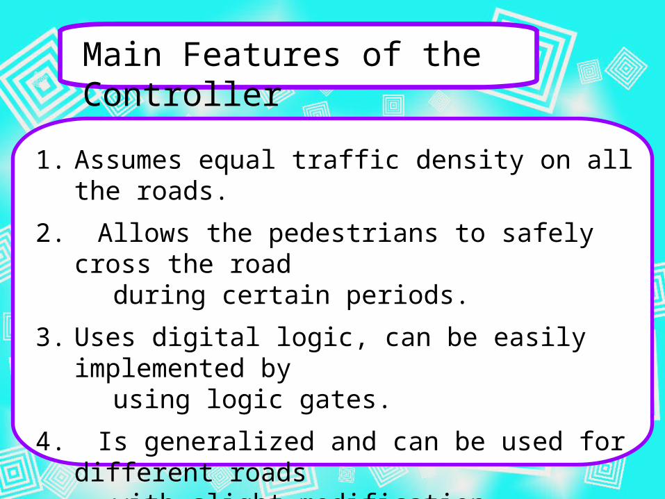
Main Features of the Controller
1. Assumes equal traffic density on all the roads.
2. Allows the pedestrians to safely cross the road during certain periods.
3. Uses digital logic, can be easily implemented by using logic gates.
4. Is generalized and can be used for different roads with slight modification.
5. Can also be exercised manually when desired.

Brief Procedure to Design the Controller
Traffic Flow Diagram
Simultaneous States Table
Boolean Expressions
Circuit Diagram
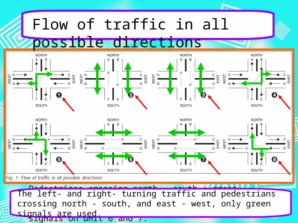
Time period for which green, yellow, and red signals remain ‘on’ (and then repeat) for the straight moving traffic is divided into 8 units.
Pedestrians crossing north – south : green signals on unit 2 and 3. Pedestrians crossing east – west : green signals on unit 6 and 7.
The left- and right- turning traffic and pedestrians crossing north - south, and east - west, only green signals are used.
Flow of traffic in all possible directions

Simultaneous States of Signals
This Simultaneous States Table is obtained from Traffic Flow Diagram.
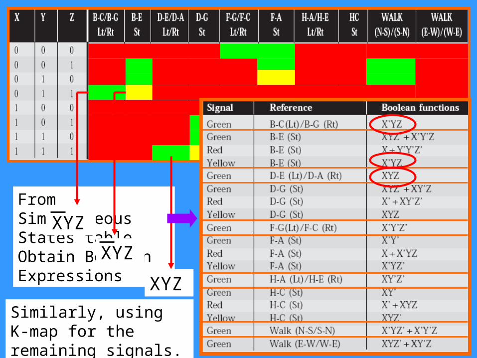
Similarly, using K-map for the remaining signals.
From Simultaneous States table, Obtain Boolean Expressions
XYZ
XYZ
XYZ

Boolean Functions

Circuit Diagram
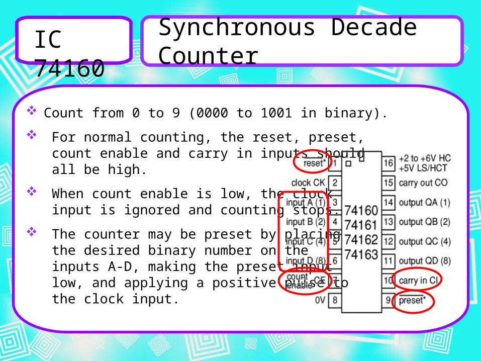
IC 74160
Synchronous Decade Counter
Count from 0 to 9 (0000 to 1001 in binary).
For normal counting, the reset, preset, count enable and carry in inputs should all be high.
When count enable is low, the clock input is ignored and counting stops.
The counter may be preset by placing the desired binary number on the inputs A-D, making the preset input low, and applying a positive pulse to the clock input.
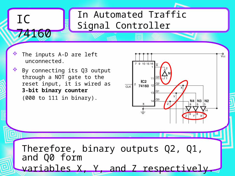
IC 74160
In Automated Traffic Signal Controller
The inputs A-D are left unconnected.
By connecting its Q3 output through a NOT gate to the reset input, it is wired as 3-bit binary counter (000 to 111 in binary).
Therefore, binary outputs Q2, Q1, and Q0 formvariables X, Y, and Z respectively.
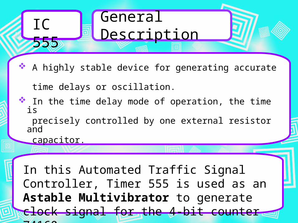
IC 555
A highly stable device for generating accurate time delays or oscillation.
In the time delay mode of operation, the time is precisely controlled by one external resistor and
capacitor.
General Description
In this Automated Traffic Signal Controller, Timer 555 is used as an Astable Multivibrator to generate clock signal for the 4-bit counter 74160.
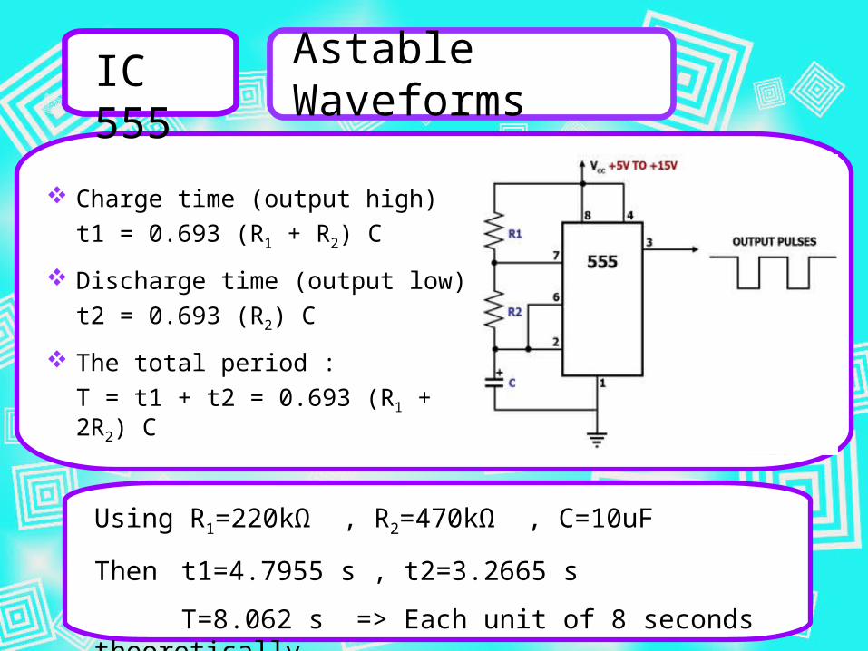
Charge time (output high)
t1 = 0.693 (R1 + R2) C
Discharge time (output low)
t2 = 0.693 (R2) C
The total period :
T = t1 + t2 = 0.693 (R1 + 2R2) C
IC 555
Astable Waveforms
Using R1=220kΩ , R2=470kΩ , C=10uF
Then t1=4.7955 s , t2=3.2665 s
T=8.062 s => Each unit of 8 seconds theoretically.
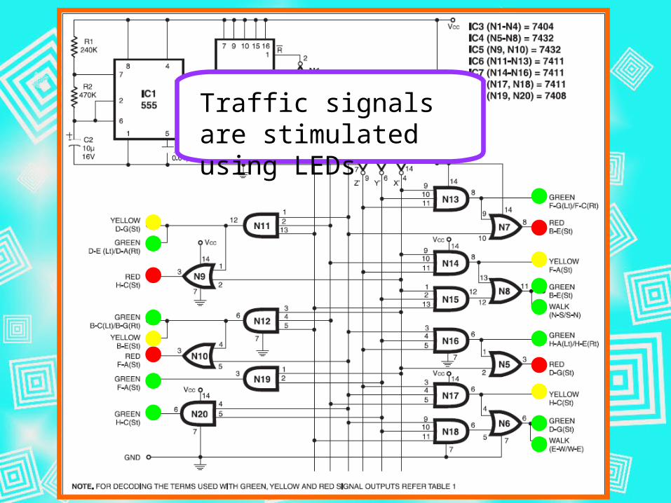
Traffic signals are stimulated using LEDs

Rig-up Circuit on Breadboard

Bibliography
Digital Logic Applications and Design by John M. Yarbrough, Thomson
Fundamentals of Electronic Devices and Circuits by David A. Bell
Fundamentals of Logic Design by Charles H. Roth, Thomson
Synchronous Up/Down Counter by Stan, M. R. and Bufieson, W. P.
http://www.electronicsforu.com/efylinux/circuit/nov2002/traffic.pdf
http://www.kpsec.freeuk.com/components/74series.htm http://en.wikipedia.org/wiki/555_timer_IC

END