Embed Size (px)
Citation preview
AUTOMATIC EXTRACTION OF RIDGE AND VALLEY
AXES USING THE PROFILE RECOGNITION AND
POLYGON-BREAKING ALGORITHM
YET-CHUNG CHANG, GWO-SHYH SONG, and SHU-KUN HSU
Institute ofOceanography,National TaiwanUniversity, P.O. Box 23-13, Taipei, Taiwan, Republic of China(e-mail: [email protected])
(Received 23 May 1996; accepted 9 July 1997)
AbstractÐFor most interpreters working on two-dimensional data or maps, a line-drawing process todepict linear and curvilinear features is often needed. One of the main di�culties in simulating humaninsight in such a process by computer is that the human eye is able to consider data trends within awide range on the map. A program based on the pro®le recognition and polygon-breaking algorithmsis introduced in this paper to extract automatically ridge and valley axes. The two algorithms arecapable of simulating human performance in the line-drawing process over a range of conditions. Theprogram starts from a pro®le recognition process which takes all the points close to the possible axes astargets and connects them as a belt of closed polygons. Then, a polygon-breaking process resolves thebelt into a continuous line, and a smoothing process further makes the line as smooth as one depictedmanually. The program has been applied to the topography of Taiwan and has been successful inextracting ridge and valley systems. It also has shown some potential in solving the problems of linedrawing for other purposes and for other kinds of data. # 1998 Elsevier Science Ltd. All rightsreserved
Key Words: Line, Ridge, Pro®le, Polygon.
INTRODUCTION
The linear or curvilinear features on many types of
maps and digital images, such as the ridge axes on
a topographic map, the re¯ector lines on a seismic
pro®le or the lineaments on a satellite image, are of
considerable importance for interpretion. To extract
information from maps and images, interpreters
generally need a line-drawing process to identify the
features. Recently, some automatic line-extraction
processes have been developed for several kinds of
two-dimensional data. Some examples of these are
the segment tracing algorithm (STA) by Koike,
Nagano and Michito (1995) for digital images, seis-
mic skeletonization by Lu and Cheng (1990), and
the automated drainage network extraction algor-
ithm by Chorowitz and others (1992).
However, in most situations, such automatic pro-
cesses have not been widely accepted and the task
of line drawing still is done manually. In the
authors' opinion, the main reason for this is that
the human interpreter can consider data trends
within a wide spatial range more e�ectively than
most automatic algorithms suggested to date. It is
noted that individual recognition of a ``target'' line
is less important than line continuity according to
data trends. The key point in simulating human
capabilities is how to design an automatic process
that can consider the data trend over a wide spatial
range.With this purpose in mind, some e�orts have
been made in the development of several automatic
processes. For instance, the computation range ofthe STA has been extended to an 11� 11 matrix(Koike, Nagano and Michito, 1995) and attempts
have been made to include three traces into the cor-relation function of the seismic skeletonizationinstead of two (Lu and Cheng, 1990). In this paper,the pro®le recognition and polygon-breaking algor-
ithm (PPA) is proposed, which approaches therequirement of a wide spatial range in a di�erentway.
PROCEDURES OF THE PPA
The main procedures of the PPA program are
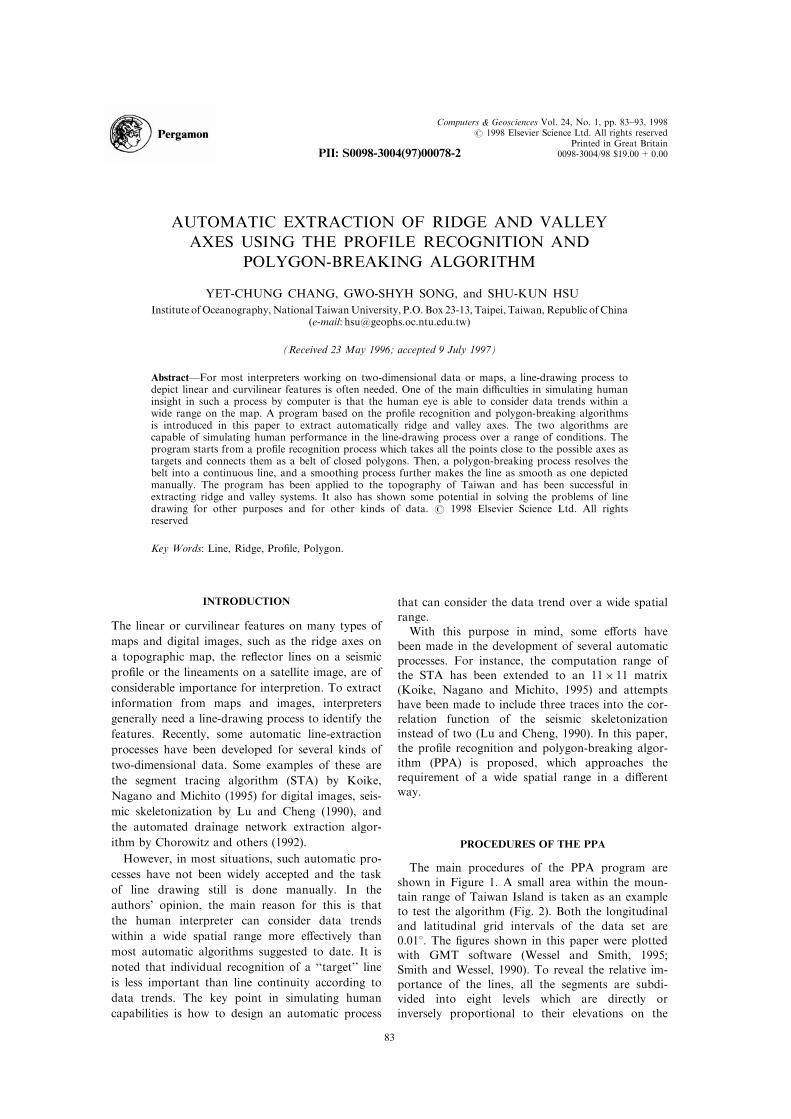
shown in Figure 1. A small area within the moun-tain range of Taiwan Island is taken as an exampleto test the algorithm (Fig. 2). Both the longitudinal
and latitudinal grid intervals of the data set are0.018. The ®gures shown in this paper were plottedwith GMT software (Wessel and Smith, 1995;
Smith and Wessel, 1990). To reveal the relative im-portance of the lines, all the segments are subdi-vided into eight levels which are directly orinversely proportional to their elevations on the
Computers & Geosciences Vol. 24, No. 1, pp. 83±93, 1998# 1998 Elsevier Science Ltd. All rights reserved
Printed in Great Britain0098-3004/98 $19.00+0.00PII: S0098-3004(97)00078-2
83
®gures. For example, the relatively higher ridgeaxes are plotted as thicker or darker lines.
Target recognition
The recognition is done with an algorithm that is
termed pro®le recognition. All the points that canbe recognized as part of a ridge shape along a pro-®le with limited length are taken as ridge targets.
The algorithm ®rst takes the current processedpoint as the center of the pro®le. If it can ®nd atleast one point lower than the central one on both
sides of the pro®le, the central point is taken as aridge target. Furthermore, the pro®le is switchedfrom N±S, NE±SW, E±W to NW±SE to check
whether the point is a target or not.This is a relatively loose recognition process com-
pared to traditional shape recognition because, evenif a point is not a local high along any direction, it
still is possible to accept it as a ridge target. Forexample, if a pro®le length equal to 7 points withelevations of 1, 2, 3, 4, 3, 2 and 1, then not only is
Target recognition
Data input
Target Connection
Segment check-out
1. Polygon breaking
2. Branch reduction
Line smoothing
Figure 1. Flowchart of PPA program.
Figure 2. Contours of test area. Background is shaded image based on elevation; higher places arebrighter. Map in lower left corner shows position of test area in Taiwan.
Y.-C. Chang G.-S. Song and S.-K. Hsu84
the central point with elevation of 4 recognized, but
so are its two closest neighbors. If, on the other
hand, the user takes a pro®le length equal to 3, the
pro®le recognition is reduced to a pure shape recog-
nition.
The advantage of pro®le recognition is that some
ambiguous targets, such as a ¯at bottom of a valley
or a ¯at top of a ridge, also can be con®rmed as
targets by the points farther beyond the neighbors.
This is important to guarantee the continuity of the
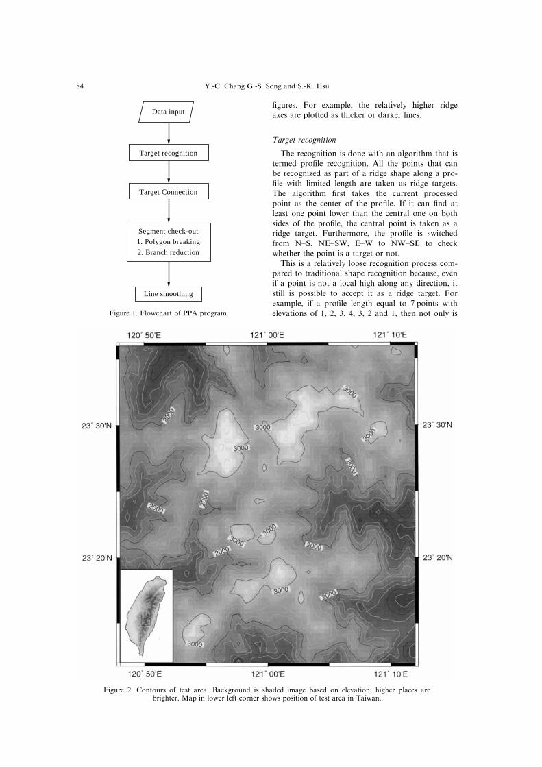
Figure 3. Targets and connections as decided by target recognition and connection processes. Targetsare represented by open circles, whereas connections are represented by segments with thickness pro-
portional to elevation.
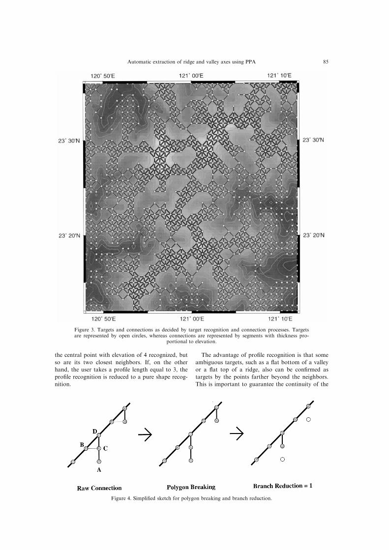
Figure 4. Simpli®ed sketch for polygon breaking and branch reduction.
Automatic extraction of ridge and valley axes using PPA 85
axial lines. In this program, if a longer than necess-
ary pro®le is taken, the result is not greatly chan-ged. Nevertheless, a long pro®le results in too manytargets and tends to waste computation time.
Additionally, the branch reduction algorithm whichfollows, and is designed to reduce the ambiguitycaused by pro®le recognition, might somewhat
over-simplify the results. Hence, it is suggested thatpro®le length is selected to be a length just longenough to recognize the possible ambiguous targetson the map.
The open circles in Figure 3 show the results ofridge target recognition following this process in thetest area. In this instance, the pro®le length is taken
as 5 points which is long enough to guarantee thecontinuity of the ridge axes in the test area.
Target connection
Once target recognition has been accomplished,every two neighboring target points are connectedinto a segment. For this program, in a 9-pointgridded cell, the central point has eight neighbors
which are memorized as number 1 for the northern
point through number 8 for the other points in aclockwise direction. Under this approach, many di-agonal connections cross each other and make
many new junction points which are not located onthe gridded nodes. When such a situation occurs,the process automatically gets rid of the less import-
ant segments; for example, in a ridge search case,the segment with lower elevation is eliminated. Theresults of target connection in the test area areshown in Figure 3 as segments with di�erent thick-
ness proportional to their elevations.
Segment check-out
After the process of A and B, it is guaranteed
that all possible axes are con®rmed within the con-nected segment groups. In this process, the unfa-vored segments are cautiously eliminated one by
one without breaking the continuity of the lines.Polygon breaking The polygon breaking is a
repeated procedure to check the closed polygon andeliminate the least important segment within each
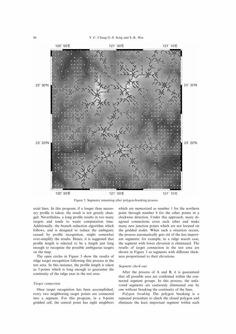
Figure 5. Segments remaining after polygon-breaking process.
Y.-C. Chang G.-S. Song and S.-K. Hsu86
polygon until no closed polygon of any size
remains. The relative importance of segments is
determined by their elevation; for instance, for
ridge depiction, the segment with lower elevation is
less important than segments with higher elevation.
After this process, the lines so formed become pure
dendritic patterns whose axes are composed of con-
tinuous segment groups with many branches instead
of a belt of closed polygons.
For each round of polygon breaking in this pro-
gram, the tracing ``tour'' starts from one end of
the weakest segment which has not been checked
previously. When the tracing tour returns to either
end of this segment, the tracing stops. Because the
possible candidate polygons which may include the
segment in question may exist on either side of it,
the tracing process is executed in both clockwise
and counter-clockwise directions. Referring to the
example shown in Figure 4, if the segment B±C is
taken as a weak segment and the tracing starts
from the target B clockwise, then the tour is B±
D±C and a polygon is checked. Once the segment
is veri®ed as part of a closed polygon, it is elimi-
nated and the polygon is broken. In the other
hand, if the tracing starts from target A, no poly-
gon will be found and the connection between A
and C saved.
A main problem for this process is that both the
search for the weakest segment in the data set, and
the tracing actions, both take much computation
time. To solve part of this problem, the real connec-
tion status between targets and the possible tracing
routes are handled separately. Once a segment has
been checked by the polygon-breaking process, it is
taken o� of the possible route table, and no tracing
tour will pass it again. Additionally, if a segment is
veri®ed as an end-segment, it is also removed from
the route table. For either of these two situations,
the segment is de®nitely not part of any closed
polygon. Such a design can reduce computation
time by 50% without a�ecting the results of the
process.
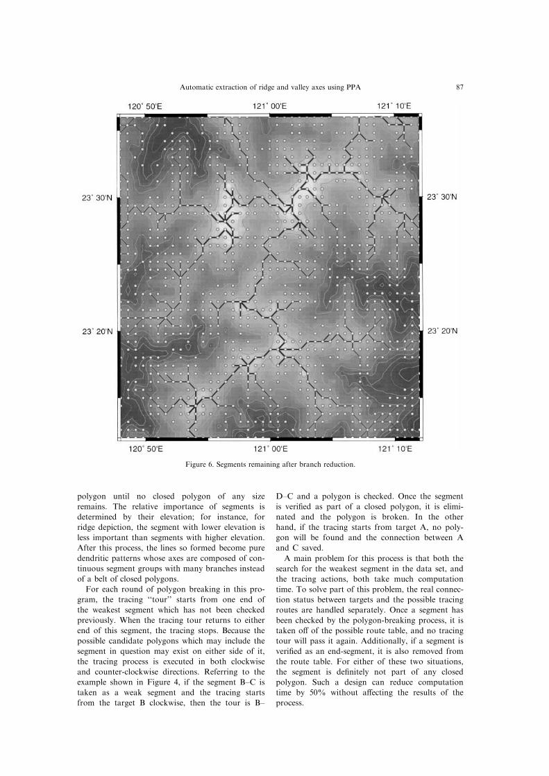
Figure 6. Segments remaining after branch reduction.
Automatic extraction of ridge and valley axes using PPA 87
Branch reduction After polygon breaking, many
short branches remain besides the axes (Fig. 5).
Most of them are undesirable side e�ects of pro®le
recognition which generates some over-determined
targets around the true axes. As mentioned in the
pro®le recognition section, if a pro®le length of
7 points is taken, then the width of an axis may be
expanded from 1 to 3. In this instance, after the
polygon breaking, it is possible that many pseudo-
branches shorter than three segments remain beside
the true axis. Therefore, in this process all the
branches are reduced to one half of the pro®le
length. The result of branch reduction is shown in
Figure 6, in which the reduction length is 2 points.
The actions taken for this process are:
1. all the end-points are located;
2. the connections of those end-points are elimi-
nated; and
3. round = round + 1; if the round is less than the
(pro®le length)/2; step (1) is repeated.
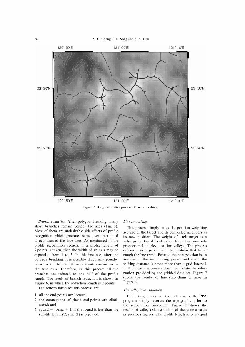
Line smoothing
This process simply takes the position weighting
average of the target and its connected neighbors asits new position. The weight of each target is avalue proportional to elevation for ridges, inversely
proportional to elevation for valleys. The processcan result in targets moving to positions that bettermatch the line trend. Because the new position is an
average of the neighboring points and itself, theshifting distance is never more than a grid interval.In this way, the process does not violate the infor-mation provided by the gridded data set. Figure 7
shows the results of line smoothing of lines inFigure 6.
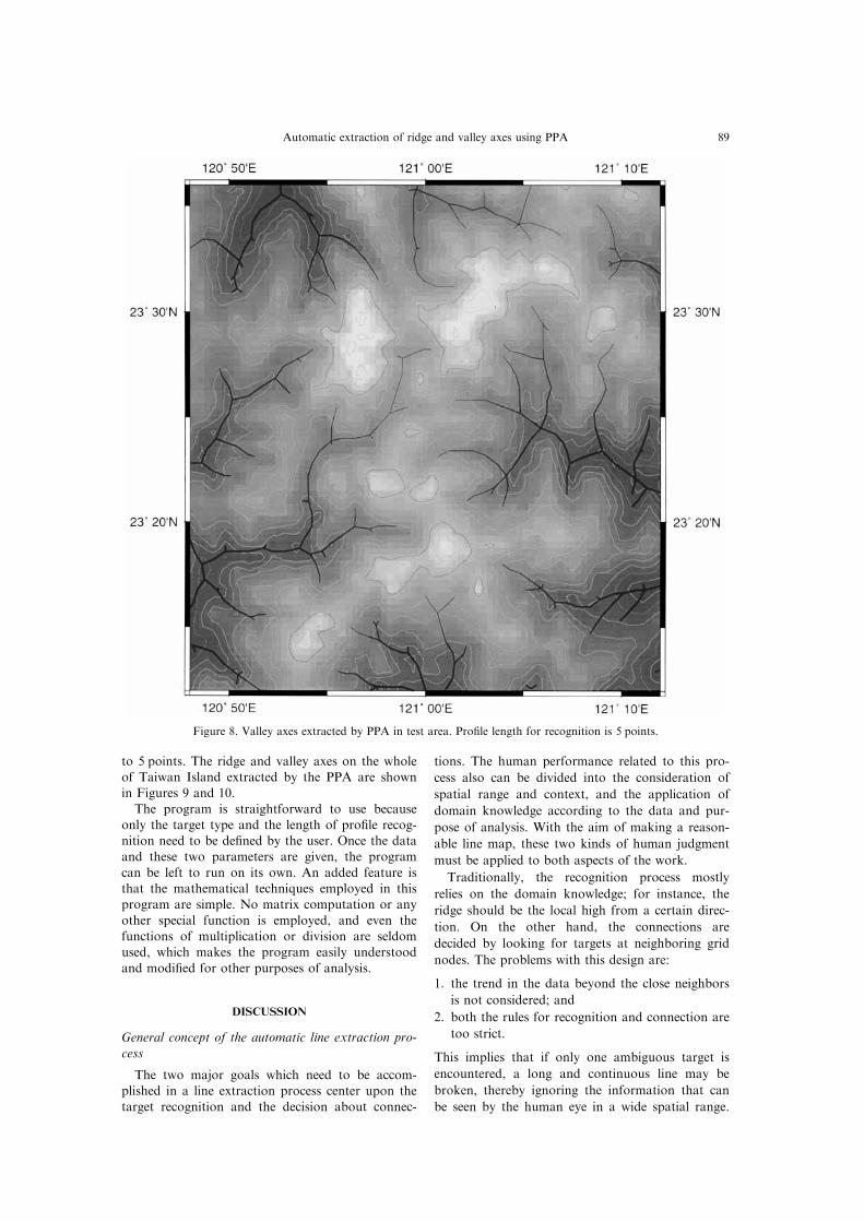
The valley axes situation
If the target lines are the valley axes, the PPA
program simply reverses the topography prior tothe recognition procedure. Figure 8 shows theresults of valley axis extraction of the same area asin previous ®gures. The pro®le length also is equal
Figure 7. Ridge axes after process of line smoothing.
Y.-C. Chang G.-S. Song and S.-K. Hsu88
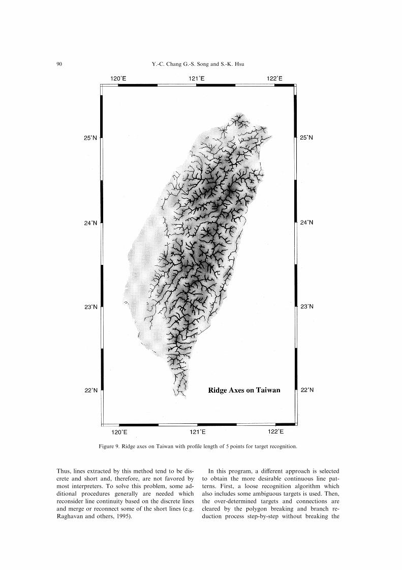
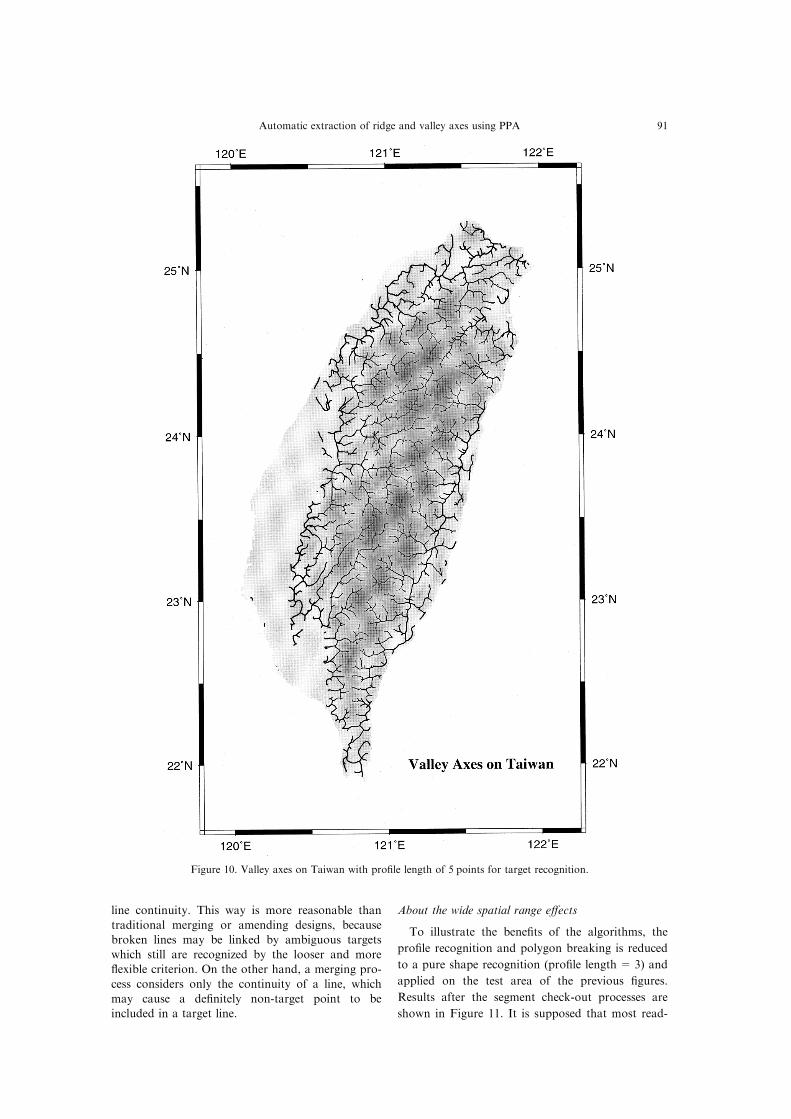
to 5 points. The ridge and valley axes on the wholeof Taiwan Island extracted by the PPA are shownin Figures 9 and 10.
The program is straightforward to use becauseonly the target type and the length of pro®le recog-nition need to be de®ned by the user. Once the dataand these two parameters are given, the program
can be left to run on its own. An added feature isthat the mathematical techniques employed in thisprogram are simple. No matrix computation or any
other special function is employed, and even thefunctions of multiplication or division are seldomused, which makes the program easily understood
and modi®ed for other purposes of analysis.
DISCUSSION
General concept of the automatic line extraction pro-cess
The two major goals which need to be accom-plished in a line extraction process center upon thetarget recognition and the decision about connec-
tions. The human performance related to this pro-
cess also can be divided into the consideration of
spatial range and context, and the application of
domain knowledge according to the data and pur-
pose of analysis. With the aim of making a reason-
able line map, these two kinds of human judgment
must be applied to both aspects of the work.
Traditionally, the recognition process mostly
relies on the domain knowledge; for instance, the
ridge should be the local high from a certain direc-
tion. On the other hand, the connections are
decided by looking for targets at neighboring grid
nodes. The problems with this design are:
1. the trend in the data beyond the close neighbors
is not considered; and
2. both the rules for recognition and connection are
too strict.
This implies that if only one ambiguous target is
encountered, a long and continuous line may be
broken, thereby ignoring the information that can
be seen by the human eye in a wide spatial range.
Figure 8. Valley axes extracted by PPA in test area. Pro®le length for recognition is 5 points.
Automatic extraction of ridge and valley axes using PPA 89
Thus, lines extracted by this method tend to be dis-
crete and short and, therefore, are not favored by
most interpreters. To solve this problem, some ad-
ditional procedures generally are needed which
reconsider line continuity based on the discrete lines
and merge or reconnect some of the short lines (e.g.
Raghavan and others, 1995).
In this program, a di�erent approach is selected
to obtain the more desirable continuous line pat-
terns. First, a loose recognition algorithm which
also includes some ambiguous targets is used. Then,
the over-determined targets and connections are
cleared by the polygon breaking and branch re-
duction process step-by-step without breaking the
Figure 9. Ridge axes on Taiwan with pro®le length of 5 points for target recognition.
Y.-C. Chang G.-S. Song and S.-K. Hsu90
line continuity. This way is more reasonable than
traditional merging or amending designs, because
broken lines may be linked by ambiguous targets
which still are recognized by the looser and more
¯exible criterion. On the other hand, a merging pro-
cess considers only the continuity of a line, which
may cause a de®nitely non-target point to be
included in a target line.
About the wide spatial range e�ects
To illustrate the bene®ts of the algorithms, the
pro®le recognition and polygon breaking is reduced
to a pure shape recognition (pro®le length = 3) and
applied on the test area of the previous ®gures.
Results after the segment check-out processes are
shown in Figure 11. It is supposed that most read-
Figure 10. Valley axes on Taiwan with pro®le length of 5 points for target recognition.
Automatic extraction of ridge and valley axes using PPA 91

ers will expect the line to be connected at site B on
Figure 11 rather than site A. However, the compu-
ter did not make any mistake! The disconnection at
site B is simply because the topography is ``¯at''
with respect to the neighboring data points at that
location. On the other hand, the connection at site
A is because the point is recognized as a target with
respect to the neighboring data. In fact, the reason
for favoring the connection at B rather than A is
that a zone wide enough to include both A and B
simultaneously can be considered by a human in-
terpreter. If the eye and brain could not consider a
wide zone, then the human decision would be the
same as the one made by an automatic process.
In this program, pro®le recognition is a pro-
cedure which recognizes the target based on a wide
zone extending beyond the immediate neighbors. If
a target cannot be con®rmed by the immediate
neighbors, then the data points farther away pro-
vide more information for recognition. For
example, if the pro®le length is extended from three
to ®ve, both sites A and B are connected (seeFig. 3). On the other hand, the polygon-breaking
step helps to disconnect polygons from smaller onesto a larger one. When the remaining polygon iswide enough to include both the connections atsites A and B, their relative importance is taken
into consideration simultaneously and the connec-tion at A is cancelled (see Fig. 5). In other words,the program can consider the property of many seg-
ments distributed over a wide spatial range on themap and make a single decision of connection ornot by the polygon-breaking process.
About the valley axes extraction
It is noted that the valley axes pattern decided bythe PPA is similar to a drainage system (see Fig. 8).The main di�erence of the results between the PPA
and the traditional automated drainage extractionprograms (e.g. Chorowitz and others, 1992;O'Callaghan and Mark, 1984) is that the latter gen-erally ®ll the depressions to guarantee continuous
Figure 11. Segments remaining after polygon breaking and branch reduction processes. Pro®le lengthfor recognition is 3 points.
Y.-C. Chang G.-S. Song and S.-K. Hsu92
downslope gradients, but the PPA simply depictsthe topographic low axes. However, if some criteria
to characterize the drainage were included, the pro-gram also might provide an alternative to existingmethods of extracting the drainage system.
CONCLUSION
A new concept that involes consideration of awide spatial range is proposed to extract topo-
graphic information automatically. To simulate theprocess of human interpretation, the proposed al-gorithm employs a relatively loose pro®le recog-
nition criteria to include both clear and ambiguoustargets and connect them as belts of closed poly-gons. An iterative and rigorous step of polygonbreaking is used to eliminate the least important
segments without breaking line continuity. Theremaining segments are ®nally smoothed by shiftingthe connected targets lines to positions guided by
trends in the data.
REFERENCES
Chorowitz, J., Ichoko, C., Riazano�, S. and Kim,Y. J. (1992) A combined algorithm for automated drai-nage network extraction. Water Resources Research 28,1293±1302.
Koike, K., Nagano, S. and Michito, O. (1995) Lineamentanalysis of satellite images using a segment tracing al-gorithm (STA). Computers & Geosciences 21(9), 1091±1104.
Lu, S. Y. and Cheng, Y. C. (1990) An iterative approachto seismic skeletonization. Geophysics 55(10), 1312±1320.
O'Callaghan, J. F. and Mark, D. M. (1984) The extractionof drainage networks from digital elevation data.Computer Vision, Graphics and Image Processing28, 323±344.
Raghavan, V., Matsumoto, S., Koike, K. and Nagano,S. (1995) Automatic lineament extraction from digitalimages using a segment tracing and rotation transform-ation approach. Computers & Geosciences 21(4) , 555±591.
Smith, W. H. F. and Wessel, P. (1990) Gridding with con-tinuous curvature splines in tension. Geophysics55, 293±305.
Wessel, P. and Smith, W. H. F. (1995) New version of theGeneric Mapping Tools released. EOS TransactionsAmerican Geophysical Union 76, 329.
Automatic extraction of ridge and valley axes using PPA 93


![Alveolar Ridge Preservation after Tooth Extraction Using ... · ridge resorption rate and bone remodelling after tooth extraction [15]. Autogenous bone as bone graft material is still](https://img.pdfslide.net/doc/110x75/5ed57c6a0bd3843450408daa/alveolar-ridge-preservation-after-tooth-extraction-using-ridge-resorption-rate.jpg)