Embed Size (px)
Citation preview

The author(s) shown below used Federal funds provided by the U.S. Department of Justice and prepared the following final report: Document Title: Automatic Fingerprint Matching Using Extended
Feature Set Author: Anil K. Jain Document No.: 235577
Date Received: August 2011 Award Number: 2007-RG-CX-K183 This report has not been published by the U.S. Department of Justice. To provide better customer service, NCJRS has made this Federally-funded grant final report available electronically in addition to traditional paper copies.
Opinions or points of view expressed are those
of the author(s) and do not necessarily reflect the official position or policies of the U.S.
Department of Justice.

Automatic Fingerprint MatchingUsing Extended Feature Set
Final Report
Award Number: 2007-RG-CX-K183
Anil K. JainDepartment of Computer Science and Engineering
Michigan State [email protected]
August 23, 2011
Abstract
Fingerprint friction ridge features are generally described in a hierarchical or-
der at three different levels, namely, Level 1 (ridge flow), Level 2 (minutiae points)
and Level 3 (pores and ridge shape, etc.). Current Automated Fingerprint Iden-
tification Systems (AFIS) generally rely only on a subset of Level 1 and Level 2
features (minutiae and core/delta) for matching. On the other hand, latent print
examiners frequently take advantage of a much richer set of features naturally
occurring in fingerprints. It is believed that this difference may be one of the rea-
sons for the superior performance of fingerprint examiners over AFIS, particularly
in case of difficult latent matches. Fingerprint features, other than minutiae and
core/delta, are also referred to as the extended feature set (EFS). The goal of this
study is to i) develop algorithms for encoding and matching extended features, ii)
develop fusion algorithms to combine extended features with minutiae information
to improve fingerprint matching accuracy, and iii) understand the contributions of
various extended features in latent fingerprint matching.
We study a number of extended features at all three levels, including ridge
flow map, ridge wavelength map, ridge quality map, ridge skeleton, pores, dots,
incipient ridges, and ridge edge protrusions. Feature extraction and matching algo-
rithms are developed for each type of feature. Relative contribution of each feature
towards the overall matching accuracy is evaluated by incrementally adding fea-
tures to baseline features (minutiae and core/delta). The order of adding features
is determined based on the amount of manual labour in feature marking and the
estimated importance of features. Latent fingerprint databases, NIST SD27 and
ELFT-EFS-PC, and several NIST rolled/plain fingerprint databases are used in our
experiments.
Based on extensive experiments, we report the following findings: i) almost all
the extended features lead to some improvement in latent matching accuracy, ii)
extended features at higher level are more effective in improving latent matching
accuracy than those at lower level, iii) high image resolution (at least 1000 ppi) is
necessary but not sufficient for reliably capturing Level 3 features.
Based on our study, we would like to offer the following recommendations: i)
extended features at Level 1 and Level 2 are strongly recommended to be incorpo-
rated into AFIS, ii) convenient GUI tools should be developed to help fingerprint
examiners manually mark extended features (especially ridge skeleton) at Level 1
and Level 2 in latents, iii) it is crucial to improve the quality of enrolled fingerprints
(so that a sufficient number of Level 3 features can be extracted) before Level 3
features can play an important role in AFIS.
1

ContentsExecutive Summary 3
1 Introduction 71.1 Statement of the problem . . . . . . . . . . . . . . . . . . . . . . . . 8
1.2 Literature review . . . . . . . . . . . . . . . . . . . . . . . . . . . . 8
1.3 Rationale for the research . . . . . . . . . . . . . . . . . . . . . . . . 8
2 Methods 102.1 Features . . . . . . . . . . . . . . . . . . . . . . . . . . . . . . . . . 10
2.2 Feature Extraction . . . . . . . . . . . . . . . . . . . . . . . . . . . . 10
2.2.1 Level 1 and Level 2 . . . . . . . . . . . . . . . . . . . . . . . 10
2.2.2 Level 3 . . . . . . . . . . . . . . . . . . . . . . . . . . . . . 11
2.3 Matching . . . . . . . . . . . . . . . . . . . . . . . . . . . . . . . . 14
2.3.1 Level 1 and Level 2 . . . . . . . . . . . . . . . . . . . . . . . 14
2.3.2 Level 3 . . . . . . . . . . . . . . . . . . . . . . . . . . . . . 19
3 Results 253.1 Statement of results . . . . . . . . . . . . . . . . . . . . . . . . . . . 25
3.1.1 Level 1 and Level 2 . . . . . . . . . . . . . . . . . . . . . . . 25
3.1.2 Level 3 . . . . . . . . . . . . . . . . . . . . . . . . . . . . . 26
3.2 Tables . . . . . . . . . . . . . . . . . . . . . . . . . . . . . . . . . . 31
3.3 Figures . . . . . . . . . . . . . . . . . . . . . . . . . . . . . . . . . 32
4 Conclusions 494.1 Discussion of findings . . . . . . . . . . . . . . . . . . . . . . . . . . 49
4.2 Implications for policy and practice . . . . . . . . . . . . . . . . . . 49
4.3 Implications for further research . . . . . . . . . . . . . . . . . . . . 49
5 Bibliography 51
6 Dissemination 566.1 Publications . . . . . . . . . . . . . . . . . . . . . . . . . . . . . . . 56
6.1.1 Journal Papers . . . . . . . . . . . . . . . . . . . . . . . . . 56
6.1.2 Conference Papers . . . . . . . . . . . . . . . . . . . . . . . 56
6.1.3 Technical Reports . . . . . . . . . . . . . . . . . . . . . . . . 56
6.2 Presentations . . . . . . . . . . . . . . . . . . . . . . . . . . . . . . 57
6.2.1 Conference Presentations . . . . . . . . . . . . . . . . . . . . 57
6.2.2 Invited Talks . . . . . . . . . . . . . . . . . . . . . . . . . . 57
Appendix 58
2
Executive Summary
IntroductionOver the past 40 years, Automated Fingerprint Identification Systems (AFIS) have
played a major role in forensics and criminal investigations. However, these systems
have not yet eliminated the need for manual examination and matching of fingerprints
by experienced human experts, particularly for latent prints. This is mainly because
“AFIS technology, since its onset, has utilized a very limited amount of fingerprint
detail. Latent print experts rely on far more information in effecting individualiza-
tions/exclusions than just ending ridges and bifurcations” [50].
Fingerprint features are generally categorized into three levels [6]. Level 1 features
are the macro details of the fingerprint such as ridge flow and pattern type. Level 2
features refer to the Galton characteristics or minutiae, such as ridge bifurcations and
endings. Level 3 features include all dimensional attributes of the ridge such as ridge
path deviation, width, shape, pores, edge contour, incipient ridges, breaks, creases,
scars, and other permanent details. The current FBI standard of fingerprint resolution
for AFIS is 500 ppi ( 50 microns pitch), which is inadequate to automatically and
reliably extract Level 3 features, such as pores ( 60 microns in radius). As a result,
state of the art AFIS technology is primarily based on Level 1 and Level 2 features.
With the advances in fingerprint sensing technology, many high resolution (i.e.,
1000 ppi) sensors are now available that makes the extraction of extended features
more feasible. The extended features that are well understood and often used by latent
experts include minutiae shape, dots and pores [6]. They are utilized in latent matching
when they are present in the input image and discernible to reach accurate conclu-
sions. Unfortunately, there have very few systematic studies on automatic fingerprint
identification using these extended features. Such studies are sorely needed with the
planned Next Generation Identification (NGI) project launched by the FBI that will use
fingerprints at 1000 ppi resolution.
At the 2005 ANSI/NIST fingerprint standard update workshop, SWGFAST [29]
proposed a minimum scanning resolution of 1000 ppi for latent, ten-print, and palm
print images and the inclusion of extended features in the FBI standard. This pro-
posal and its support by the forensic community calls for an urgent need for systematic
research in the use of extended feature set in automatic fingerprint identification. We
propose to develop an automated system that would robustly extract and match some of
the prominent extended features. This would enable us to quantify the discriminating
power of the extended features by evaluating their statistical significance.
MethodsWe study a number of extended features at all three levels, including ridge flow map,
ridge wavelength map, ridge quality map, ridge skeleton, pores, dots, incipient ridges,
and ridge edge protrusions. Feature extraction and matching algorithms are devel-
oped for each type of feature. Relative contribution of each feature to matching accu-
racy is evaluated by incrementally adding features to baseline features (minutiae and
core/delta). The order of adding features is determined based on the amount of man-
3

ual effort needed in feature marking and the estimated importance of features. Latent
fingerprint databases, NIST SD27 and ELFT-EFS-PC, and several NIST rolled/plain
fingerprint databases are used in our experiments.
Based on a conventional fingerprint feature extraction algorithm, which outputs
ridge skeleton image and minutiae, and a baseline minutiae matcher, which outputs
minutiae correspondences and minutiae match score, encoding and matching algo-
rithms are developed for extended features at three levels:
1. At Level 1, three types of extend features are considered, including ridge flow
map, ridge wavelength map, and ridge quality map. These features are used in
local matching stage to facilitate minutiae pairing as well as in global matching
stage to help separate genuine matches and impostor matches.
2. At Level 2, a ridge skeleton matching algorithm is developed. Starting with the
most similar minutiae pairs, the skeleton matching algorithm establishes skele-
ton correspondence through a skeleton propagation procedure. After skeleton
matching is finished, a skeleton match score is computed.
3. At Level 3, four types of extended features are considered, including pores, dots,
incipient ridges, and ridge edge protrusions. A topological level 3 feature match-
ing algorithm is developed for latent to full fingerprint matching. Unlike most
existing level 3 feature matching algorithms that only consider the feature loca-
tion, the proposed algorithm enforces the topological relationship between level
3 features, minutiae, and ridge skeletons.
Because the public domain 1000 ppi fingerprint databases are few and small in size,
we used different databases for extended features at different levels.
1. For experiments related to Level 1 and Level 2 features, 258 latent fingerprints
and mated rolled fingerprints in NIST SD27 are used. A total of 29K rolled
fingerprints in NIST SD4 and SD14 are additionally used as background data to
increase the gallery size. All these fingerprint images are captured at 500 ppi.
2. For experiments related to Level 3 features, 242 latent fingerprints and mated
rolled finger-prints in ELFT-EFS-PC are used. The gallery consists of 4,180
rolled fingerprints, where the additional rolled fingerprints are from NIST SD29
and SD30. All these fingerprint images are captured at 1000 ppi.
3. Because the poor quality of many latent and/or rolled fingerprints in ELFT-EFS-
PC restricts the efficacy of Level 3 features, a simulated 1000 ppi partial finger-
print database is constructed from rolled fingerprints in NIST SD30 to study the
potential values of Level 3 features. In all these databases, features in the latent
prints are manually marked, but features in the rolled fingerprints are automati-
cally extracted.
The first set of experiments is conducted to evaluate the proposed matching algo-
rithms for Level 1 and Level 2 extended features and to study the utility of various
Level 1 and Level 2 extended features.
4

1. The performance, in terms of the Cumulative Match Characteristic (CMC) curve,
of the baseline minutiae matcher is first established by matching all latents against
the 29K gallery.
2. Extended features are incrementally added (in the following order: ridge quality
map, ridge flow map, ridge wavelength map, and finally ridge skeleton) and the
test is repeated.
3. Performance improvement of each extended feature is analyzed for the whole
database as well as separately for three quality levels of latent fingerprints (spec-
ified by fingerprint examiners).
The second set of experiments is conducted to evaluate the proposed encoding and
matching algorithms for Level 3 extended features and to study the utility of various
Level 3 extended features.
1. The joint distributions of the number of Level 3 features and the number of
minutiae in latents of ELFT-EFS-PC database and the West Virginia University
(WVU) latent database are analyzed.
2. The performance, in terms of the Cumulative Match Characteristic (CMC) curve,
of the baseline minutiae matcher is first established by matching all latents in
ELFT-EFS-PC against the 4180 rolled fingerprints.
3. Extraction accuracy of Level 3 features is evaluated on the simulated partial fin-
gerprint database by comparing them to ground truth.
4. Matching experiments using Level 3 features are conducted on both ELFT-EFS-
PC and the simulated partial fingerprint database.
ResultsExperimental results are summarized as follows:
1. Extended features at Level 1 lead to the largest matching accuracy improvement
than extended features at the other two levels. Among the Level 1 extended
features, ridge quality map and ridge flow map are the most important.
2. Extended features at Level 2, namely ridge skeleton, improve the rank-1 recog-
nition rate by 5%.
3. The “ugly” latents in NIST SD27 benefit the most from using extended features
at Level 1 and Level 2. The rank-1 recognition rate for “ugly” latents using
all extended features at Level 1 is already comparable to the rank-1 recogni-
tion rate for “good” latents using the current FBI standard features (minutiae +
core/delta).
4. The contribution of Level 3 features on ELFT-EFS-PC is minor. But, on a sim-
ulated partial fingerprint database, they do show obvious improvement in the
matching accuracy.
5

ConclusionsBased on the extensive experiments, the following conclusions are made:
1. All extended features at Level 1 and Level 2 should be incorporated into AFIS as
soon as possible, since (i) these features are insensitive to image quality, (ii) do
not rely on high resolution images, and (iii) do lead to significant improvement
in the matching accuracy.
2. Algorithms and GUI tools should be developed to help fingerprint examiners
manually mark extended features in latents, since it is a time-consuming task.
3. Utility of Level 3 features heavily rely on the image quality of both latents and
enrolled fingerprints. Hence it is crucial to improve the quality of enrolled fin-
gerprints (so that a sufficient number of Level 3 features can be extracted) before
Level 3 features can play an important role in design and development of next
generation AFIS.
6
1 IntroductionOver the past 40 years, Automated Fingerprint Identification Systems (AFIS) have
played a major role in forensics and criminal investigations. However, these systems
have not yet eliminated the need for manual examination of fingerprints by experienced
human experts, particularly for latent prints. This is mainly because “AFIS technology,
since its onset, has utilized a very limited amount of fingerprint detail. Latent print
experts rely on far more information in effecting individualizations/exclusions than
just ending ridges and bifurcations” [50].
Three types of fingerprint images are commonly used in law enforcement appli-
cations: ink, live-scan, and latent (see Fig. 1). Inking method is the earliest method
for capturing and recording fingerprints. To capture the ink fingerprint images of a
subject, the finger is coated with ink and pressed or rolled against a paper card. The
print left on the card is then scanned to obtain a digital fingerprint image. Live-scan
fingerprint images are obtained by using optical, capacitive or other types of sensors
to directly image the finger. Latent fingerprint images are inadvertently left by per-
sons on surfaces of objects and are lifted or photographed by using various techniques,
e.g. chemical processing [3]. Compared to ink and live-scan fingerprint images, latent
fingerprint images are characterized by small area, poor quality, and large non-linear
distortion [56].
Fingerprint features are generally categorized into three levels [6]. Level 1 features
are the macro details of the fingerprint such as ridge flow and pattern type. Level 2
features refer to the Galton characteristics or minutiae, such as ridge bifurcations and
endings. Level 3 features include all dimensional attributes of the ridge such as ridge
path deviation, width, shape, pores, edge contour, incipient ridges, breaks, creases,
scars, and other permanent details. An example is given in Fig. 2 to show some of the
three level features. The current FBI standard of fingerprint resolution for AFIS is 500
ppi ( 50 microns pitch), which is inadequate to automatically extract Level 3 features,
such as pores ( 60 microns in radius). As a result, AFIS technology is primarily based
on Level 1 and Level 2 features.
With the advances in fingerprint sensing technology, many high resolution (i.e.,
1000 ppi) sensors are now available that makes the extraction of extended features
more feasible. The extended features that are well understood and often used by latent
experts include minutiae shape, dots and pores [6]. They have been relied upon in latent
matching when they are present and discernible to reach accurate conclusions. Unfor-
tunately, there have very few systematic studies on automatic fingerprint identification
using these extended features.
At the 2005 ANSI/NIST fingerprint standard update workshop, SWGFAST [29]
proposed a minimum scanning resolution of 1000 ppi for latent, ten-print, and palm
print images and the inclusion of extended features in the FBI standard. This proposal
and its strong endorsement by the forensic community calls for systematic research in
the use of extended feature set in automatic fingerprint identification. We propose to
develop an automated system that would robustly extract and match some of the promi-
nent extended features. This would enable us to quantify the discriminating power of
the extended features by evaluating their statistical significance.
7
1.1 Statement of the problemWe propose to develop an automated system that would robustly extract and match
some of the prominent extended features for both latent-to-full and full-to-full finger-
print matching. Using this system, we will quantify the discriminating power of the
extended features by evaluating their statistical significance.
1.2 Literature reviewIt is a common practice to improve the capability of a minutiae matcher by using
Level 1 and Level 2 features. These include singular points and pattern type [24],
ridge flow map (or orientation field) [24, 31–35], ridge wavelength map (or frequency
map) [31,36], skeleton [24,25,31,37,38], and crease [39]. However, these studies pri-
marily address full fingerprint matching and, to our knowledge, there is no published
algorithm on using extended features for latent matching. NIST has conducted an eval-
uation of latent fingerprint technology using extended feature set (ELFT-EFS) [55].
Extended feature set (EFS) was manually marked in the latent fingerprints, and their
contribution to latent search was assessed by using matchers from the participants. The
NIST evaluation showed that EFS did improve the latent search accuracy. However,
because the ELFT-EFS test did not evaluate each extended feature separately, the con-
tribution of individual features is not known from this evaluation.
There is a growing interest in using Level 3 features, such as pores [35, 40, 41, 53,
54], ridge contours [35, 41], dots and incipient ridges [42], for fingerprint matching.
It is claimed that Level 3 features contain discriminating information and can improve
the performance of matching rolled/plain to rolled/plain fingerprints. However, these
conclusions are not easy to extend to latent fingerprint matching, because
• Latent fingerprints are generally of poor quality.
• Since latent images need to be matched against rolled/plain fingerprints, the re-
peatability or consistency of Level 3 features is critical. Repeatability of Level
3 features in images acquired with different techniques is much lower than that
in [35, 41, 42] where the same sensor was used to capture both template and
query fingerprints. The survey performed by Anthonioz et al. [43] among sev-
enty latent examiners shows that there is no clear consensus on the repeatability
of Level 3 features.
• Level 3 features such as pores and ridge edges are correlated with skeleton and
ridge flow map. Therefore, it is not evident if the performance improvement
reported in [35, 41, 42] is due to Level 3 features or Level 2 features that have
been implicitly used.
1.3 Rationale for the researchThe rational for the proposed research and methods are as follows:
1. Latent examiners routinely use a rich set of fingerprint features in manual la-
tent fingerprint matching. However, current AFIS rely mainly on minutiae and
8

core/delta. Thus it is reasonable to hypothesize that the large performance gap
between AFIS and latent examiners is due to features utilized in matching.
2. Previous studies have shown that some of the extended features are able to im-
prove the matching accuracy of minutiae matcher in full fingerprint matching.
Thus it is reasonable to hypothesize that with proper algorithm design, extended
features will also help improve latent matching accuracy.
3. Extended features are not independent from each other. In fact, higher level
features can be determined from lower level features. For example, orientation
field can be determined from ridge skeletons and ridge skeletons can be deter-
mined from ridge contours. Thus it is reason-able to incrementally incorporate
each type of extended feature into AFIS and to study the additive value of each
extended feature.
4. Higher level extended features are more insensitive to image quality and resolu-
tion than lower level extended features. Thus it is reasonable to use higher level
features ahead of lower level features.
9

2 Methods
2.1 FeaturesThe proposed system utilizes the following features: Level 1 features (reference points
(core/delta), ridge quality map, ridge flow map, and ridge wavelength map), Level 2
features (minutiae and skeleton), and Level 3 features (dots, incipient ridges, pores, and
ridge edge protrusions). Since all these features are defined in the CDEFFS document
[30], we use terms that are consistent with these definitions.
• Reference points have location, direction and type (see [30]).
• Ridge flow map, ridge wavelength map, and ridge quality map are obtained by
dividing the image into non-overlapping bocks of size 16 × 16 and assigning a
single orientation, wavelength, and quality value to each block. We define three
quality levels for a block: level 0 (background), level 1 (clear ridge flow and
unreliable minutiae), and level 2 (clear minutiae).
• A minutia consists of five attributes, namely x and y coordinates, minutiae di-
rection, type, and quality. The quality of minutia is defined to have two levels: 0(unreliable) and 1 (reliable).
• A skeleton is one-pixel-wide ridge, which is traced in the thinned image and
represented as a list of points.
• Level 3 features (dots, incipient ridges, pores, and ridge edge protrusions) are
represented as a set of points.
2.2 Feature Extraction2.2.1 Level 1 and Level 2
While the features at Level 1 and Level 2 have been manually marked for 258 latents
in SD27 (see Fig. 3 for a latent in SD27 with manually marked features and Fig. 4 for
three latents in ELFT-EFS-PC with manually marked features), the rolled fingerprints
are automatically processed to obtain all the features. The feature extraction algorithm
consists of two modules: preprocessing and postprocessing. In this work, Neurotech-
nology Verifinger 4.2 SDK [44] was used as a preprocessor. Due to the presence of
background noise (characters and strokes on many fingerprints scanned from paper,
such as the rolled prints in NIST SD4, SD14, and SD27), Verifinger produces many
false minutiae. Therefore, a ridge validation algorithm is used to classify each ridge or
ridge segment as true or false, and a minutiae validation algorithm is used to classify
each minutia as false, reliable, or unreliable.
A minutia is deemed as false if it is close to the background region. A minutia is
deemed as unreliable if it forms an opposite pair with another minutia. An opposite pair
is a pair of minutiae which are spatially close but have opposite directions. Remaining
minutiae are deemed as reliable.
10
Ridge validation consists of the following two steps: 1) each ridge is broken into
multiple segments at unreliable positions; 2) the segments are grouped and those be-
longing to large groups are deemed as reliable.
A block containing true ridges is labelled as foreground; otherwise as background.
For each sample point (at intervals of 6 pixels) on each ridge, the tangent direction is
computed and the distance from the adjacent ridges on both sides is computed. The
ridge flow and ridge wavelength in each foreground block are estimated by majority
voting. Singular points are extracted by the Poincare index method [45]. An example
is given in Fig. 5 to show the results of these processing steps.
2.2.2 Level 3
Level 3 fingerprint features considered here include pores, dots, incipient ridges and
ridge edge protrusions. Pores appear as bright blobs on ridges and the other three fea-
tures appear between ridges (see Fig. 2(c)). We first discuss pore extraction, followed
by extraction algorithm for the other three features.
Pores Pores, also known as sweat pores, are located on finger ridges. They are
formed in the sixth month of gestation due to the sweat-gland ducts reaching the sur-
face of the epidermis. Once the pores are formed, they are fixed on the ridges; typically,
there are between 9 and 18 pores along a centimeter of a ridge [45]. A pore can be visu-
alized as open on one print, but as closed on another print of the same finger depending
on the finger pressure and whether it is exuding perspiration. As shown in Fig. 2(c), a
closed pore appears as an isolated dot on the ridge, while an open pore is connected to
one or both of the two valleys surrounding it. As a result, the shape and size of pores
can vary from one impression to another, and therefore only the pore position is used
in matching.
The basic idea of the proposed pore extraction method is to model the spatial
appearance of pores in fingerprint images and detect them via filtering the images
with suitable matched filters. In [53], it was shown that along the ridge tangential
orientation, the intensity profile across the pore has a Gaussian shape irrespective of
whether it is open or closed (see Figs. 6(a) and 6(b)). Based on this observation, an
anisotropic pore model was established and an adaptive pore extraction algorithm was
proposed [53]. One drawback of the method is that it sets the scale parameter in the
pore model as a constant multiple of local ridge period. Such a constant ratio param-
eter is however difficult to specify for all fingerprints, especially when large distortion
exists across the fingerprint images such as latents. As an improvement to the method
in [53], we propose a new pore matched filter based on the automatic scale selection
technique [58]. Let X and Y be the horizontal (column) and vertical (row) axes of the
global image coordinate system (x and y are the corresponding coordinates), and Vand U denote the local ridge tangential and normal orientation, respectively. Let θ be
the local ridge (tangential) orientation with respect to the X axis. The proposed pore
matched filter is defined as
P γPOR(v, u; tV , tU , θ) = −t3/4V gV V (v; tV )g(u; tU ), (1)
where
11
• (v, u) = (x cos θ − y sin θ, x sin θ + y cos θ),
• g(u; tU ) = 1/(√2πtU )e
−u2/(2tU ) is Gaussian along the ridge normal orienta-
tion and constant along the ridge tangential orientation,
• gV V (v; tV ) = (v2 + tV )/(√
2πt5V )e−v2/(2tV ) is Laplacian along the ridge tan-
gential orientation and constant along the ridge normal orientation,
• and tV and tU are, respectively, the variances along the ridge tangential orienta-
tion and the ridge normal orientation.
Note that unlike [53], we describe the intensity appearance of a pore along the ridge
tangential orientation by using a Laplacian kernel because it is more robust to noise.
The Gaussian kernel along the other orientation is used merely for smoothing the noise
along the ridge normal orientation.
In order to apply the above pore matched filters, we first divide the fingerprint
image into blocks and estimate the local ridge orientation θ. We then instantiate a
pore matched filter for each block that has dominant ridge orientation (called a well-
defined block) according to eq. 1. The parameter tU in the pore matched filter is set
to a constant because it is used merely for noise smoothing. As for the parameter tV ,
a multiscale setting is adopted so that pores of varying sizes can be detected. More
specifically, a set of pore matched filters are constructed for each well-defined block
and convolved with the block. The maximum response among the sets of pore matched
filters is binarized, resulting in the pore map; candidate pore pixels have value 1 and
the non-pore pixels have value 0.
The pore map contains some falsely detected pores. To remove them, the following
post-processing steps are conducted: (i) candidate pores which are not on ridges are
removed; (ii) connected components on the pore map whose area is either too small
or too large are discarded; (iii) connected components on the pore map are removed if
the intensity of their pixels is too low. After these post-processing operations, many
spurious pores are excluded, and each connected component in the post-processed pore
map corresponds to a pore. The centroids of these detected pores are recorded. Fig.
7(a) shows a portion of a rolled ink fingerprint image, and Fig. 7(b) shows the pores de-
tected in it by the proposed method. The pore extraction results of the latent fingerprint
image in Fig. 1(c) are shown in Fig. 7(c). Due to the poor quality of latent fingerprint
images, more false pores are detected in the latent than in the rolled image. Yet, most
of the true pores are correctly extracted in latents. Therefore, the automatic pore ex-
traction algorithm proposed here may provide useful information to latent examiners
and cut down their workload in manually marking pores.
Dots, Incipient Ridges, and Ridge Edge Protrusions (DIP) While typical ridges
stretch over a large area of fingerprints and their width varies from 100μm to 300μm[45], there are occasionally some ridges which are quite short or substantially thin (see
Fig. 2(c)). These are actually dots and incipient ridges, two additional types of level 3
features in fingerprints [6]. Unlike pores, which are present in almost every finger, dots
and incipient ridges can be found in fingerprints of only about 45% of the population
12
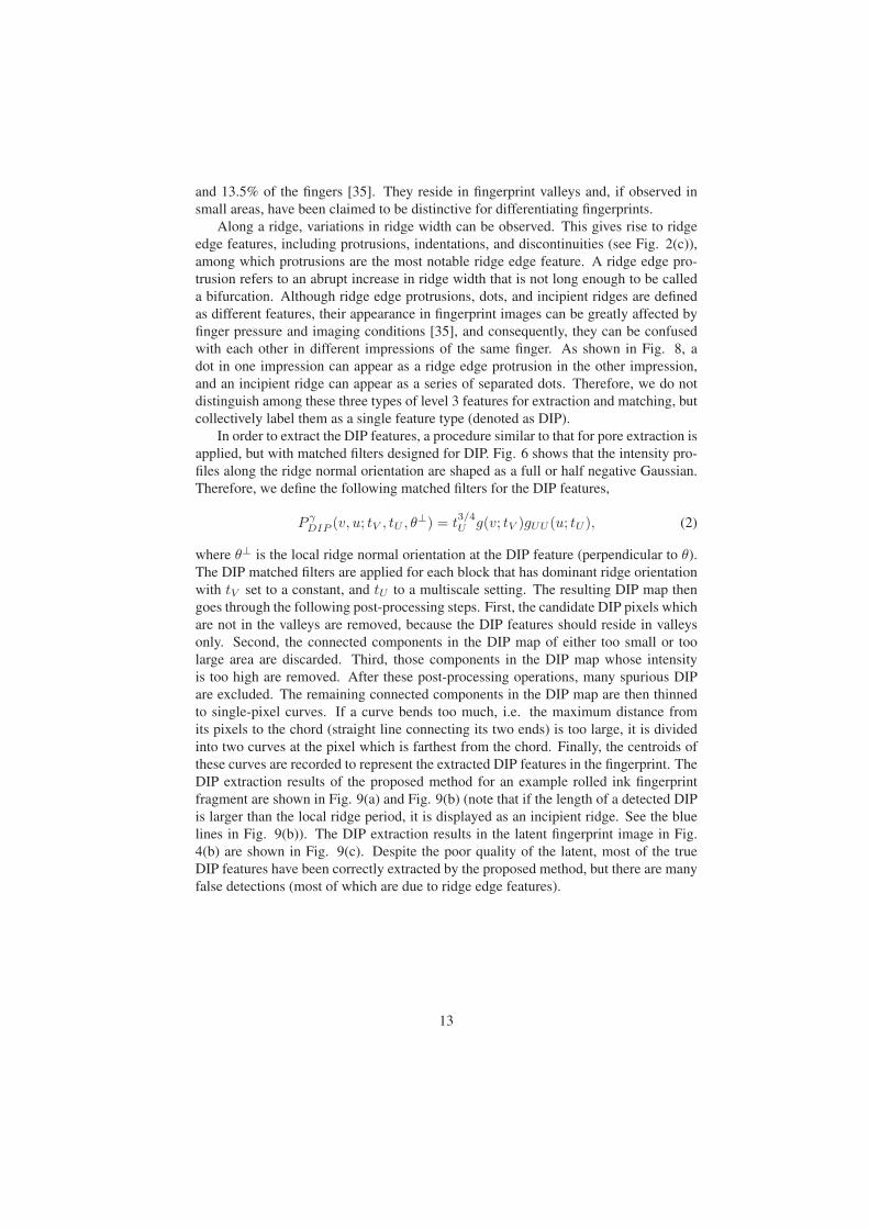
and 13.5% of the fingers [35]. They reside in fingerprint valleys and, if observed in
small areas, have been claimed to be distinctive for differentiating fingerprints.
Along a ridge, variations in ridge width can be observed. This gives rise to ridge
edge features, including protrusions, indentations, and discontinuities (see Fig. 2(c)),
among which protrusions are the most notable ridge edge feature. A ridge edge pro-
trusion refers to an abrupt increase in ridge width that is not long enough to be called
a bifurcation. Although ridge edge protrusions, dots, and incipient ridges are defined
as different features, their appearance in fingerprint images can be greatly affected by
finger pressure and imaging conditions [35], and consequently, they can be confused
with each other in different impressions of the same finger. As shown in Fig. 8, a
dot in one impression can appear as a ridge edge protrusion in the other impression,
and an incipient ridge can appear as a series of separated dots. Therefore, we do not
distinguish among these three types of level 3 features for extraction and matching, but
collectively label them as a single feature type (denoted as DIP).
In order to extract the DIP features, a procedure similar to that for pore extraction is
applied, but with matched filters designed for DIP. Fig. 6 shows that the intensity pro-
files along the ridge normal orientation are shaped as a full or half negative Gaussian.
Therefore, we define the following matched filters for the DIP features,
P γDIP (v, u; tV , tU , θ
⊥) = t3/4U g(v; tV )gUU (u; tU ), (2)
where θ⊥ is the local ridge normal orientation at the DIP feature (perpendicular to θ).
The DIP matched filters are applied for each block that has dominant ridge orientation
with tV set to a constant, and tU to a multiscale setting. The resulting DIP map then
goes through the following post-processing steps. First, the candidate DIP pixels which
are not in the valleys are removed, because the DIP features should reside in valleys
only. Second, the connected components in the DIP map of either too small or too
large area are discarded. Third, those components in the DIP map whose intensity
is too high are removed. After these post-processing operations, many spurious DIP
are excluded. The remaining connected components in the DIP map are then thinned
to single-pixel curves. If a curve bends too much, i.e. the maximum distance from
its pixels to the chord (straight line connecting its two ends) is too large, it is divided
into two curves at the pixel which is farthest from the chord. Finally, the centroids of
these curves are recorded to represent the extracted DIP features in the fingerprint. The
DIP extraction results of the proposed method for an example rolled ink fingerprint
fragment are shown in Fig. 9(a) and Fig. 9(b) (note that if the length of a detected DIP
is larger than the local ridge period, it is displayed as an incipient ridge. See the blue
lines in Fig. 9(b)). The DIP extraction results in the latent fingerprint image in Fig.
4(b) are shown in Fig. 9(c). Despite the poor quality of the latent, most of the true
DIP features have been correctly extracted by the proposed method, but there are many
false detections (most of which are due to ridge edge features).
13

2.3 Matching2.3.1 Level 1 and Level 2
To understand the relative importance of various extended features, they are incremen-
tally used for matching and the performance gains are examined. Starting with the
baseline matching algorithm, which uses only minutiae, additional features (reference
points, overall image characteristics and skeleton) are incrementally used. This order is
roughly based on the required time in manual feature marking. The baseline matching
algorithm is not only a matcher for minutiae-only templates, but also serves as a frame-
work to match and fuse various extended features. We provide a detailed description
of the baseline matcher and then describe the approaches to using various extended
features.
Baseline Matching Algorithm The baseline matching algorithm takes only minutiae
as input and consists of the following steps:
1. Local minutiae matching: Similarity between each minutia of latent fingerprint
and each minutia of rolled fingerprint is computed.
2. Global minutiae matching: Using each of the five most similar minutia pairs
found in Step 1 as an initial minutia pair, a greedy matching algorithm is used to
find a set of matching minutia pairs.
3. Matching score computation: A matching score is computed for each set of
matching minutia pairs and the maximum score is used as the matching score
between the latent and rolled prints.
Local minutiae matching In local minutiae matching, the similarity between
each minutia of latent fingerprint and each minutia of rolled fingerprint is computed.
Since the basic properties of a minutia, like location, direction and type, are not very
distinctive features, additional features, which are collectively referred to as a descrip-
tor, are computed for each minutia. Figure 10 show five types of features that have been
used as minutiae descriptors in the literature [31, 46, 47]. In the baseline algorithm,
a neighboring minutiae-based descriptor is used, since only minutiae information is
available.
The neighborhood of a minutia is defined to be a circular region with an 80-pixel
radius. All minutiae lying in this neighborhood are called the neighboring minutiae.
Let p and q be the two minutiae whose similarity needs to be computed. For each
neighboring minutia pi of p, we examine if there is a neighboring minutia of q whose
location and direction are similar to those of pi. If such a minutia exists, pi is deemed
as a matching minutia; otherwise pi is checked against the following two criteria: 1)
the minutia is unreliable, 2) it does not fall in the foreground region (the convex hull
of minutiae) when mapped to the other fingerprint based on the alignment parameters
between p and q. If pi satisfies either one of these two criteria, it will not be penalized;
otherwise, it will be penalized. The above process is also applied to the neighboring
14
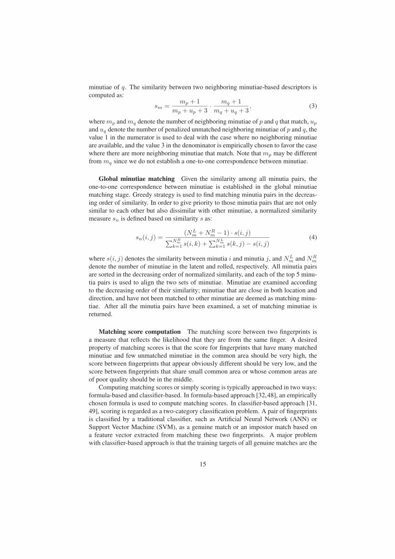
minutiae of q. The similarity between two neighboring minutiae-based descriptors is
computed as:
sm =mp + 1
mp + up + 3· mq + 1
mq + uq + 3, (3)
where mp and mq denote the number of neighboring minutiae of p and q that match, up
and uq denote the number of penalized unmatched neighboring minutiae of p and q, the
value 1 in the numerator is used to deal with the case where no neighboring minutiae
are available, and the value 3 in the denominator is empirically chosen to favor the case
where there are more neighboring minutiae that match. Note that mp may be different
from mq since we do not establish a one-to-one correspondence between minutiae.
Global minutiae matching Given the similarity among all minutia pairs, the
one-to-one correspondence between minutiae is established in the global minutiae
matching stage. Greedy strategy is used to find matching minutia pairs in the decreas-
ing order of similarity. In order to give priority to those minutia pairs that are not only
similar to each other but also dissimilar with other minutiae, a normalized similarity
measure sn is defined based on similarity s as:
sn(i, j) =(NL
m +NRm − 1) · s(i, j)
∑NRm
k=1 s(i, k) +∑NL
m
k=1 s(k, j)− s(i, j)(4)
where s(i, j) denotes the similarity between minutia i and minutia j, and NLm and NR
m
denote the number of minutiae in the latent and rolled, respectively. All minutia pairs
are sorted in the decreasing order of normalized similarity, and each of the top 5 minu-
tia pairs is used to align the two sets of minutiae. Minutiae are examined according
to the decreasing order of their similarity; minutiae that are close in both location and
direction, and have not been matched to other minutiae are deemed as matching minu-
tiae. After all the minutia pairs have been examined, a set of matching minutiae is
returned.
Matching score computation The matching score between two fingerprints is
a measure that reflects the likelihood that they are from the same finger. A desired
property of matching scores is that the score for fingerprints that have many matched
minutiae and few unmatched minutiae in the common area should be very high, the
score between fingerprints that appear obviously different should be very low, and the
score between fingerprints that share small common area or whose common areas are
of poor quality should be in the middle.
Computing matching scores or simply scoring is typically approached in two ways:
formula-based and classifier-based. In formula-based approach [32,48], an empirically
chosen formula is used to compute matching scores. In classifier-based approach [31,
49], scoring is regarded as a two-category classification problem. A pair of fingerprints
is classified by a traditional classifier, such as Artificial Neural Network (ANN) or
Support Vector Machine (SVM), as a genuine match or an impostor match based on
a feature vector extracted from matching these two fingerprints. A major problem
with classifier-based approach is that the training targets of all genuine matches are the
15
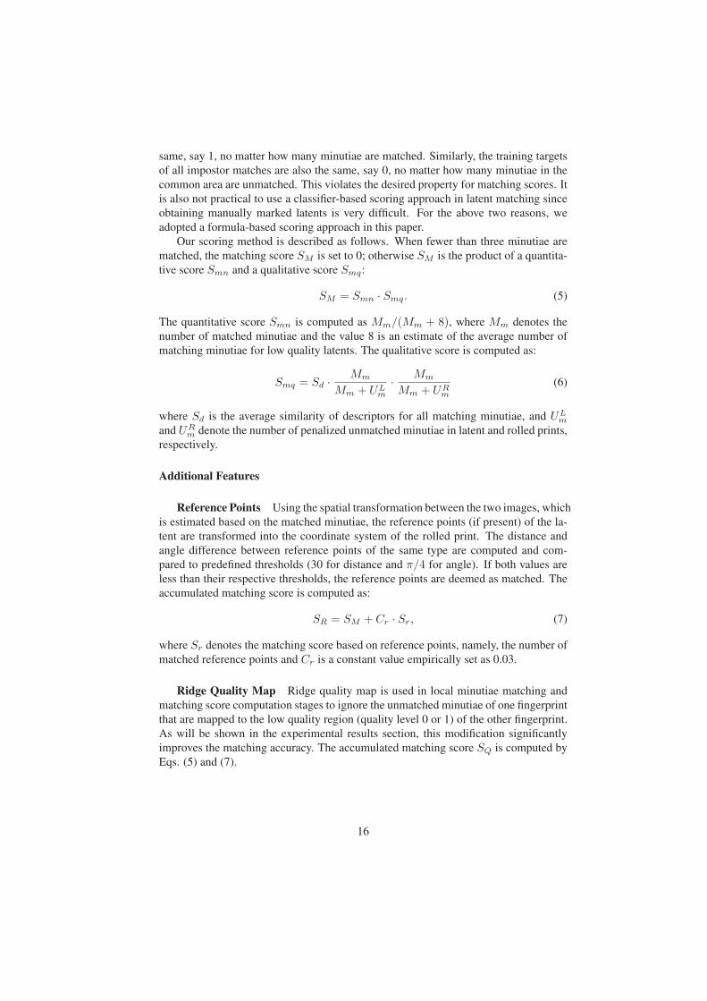
same, say 1, no matter how many minutiae are matched. Similarly, the training targets
of all impostor matches are also the same, say 0, no matter how many minutiae in the
common area are unmatched. This violates the desired property for matching scores. It
is also not practical to use a classifier-based scoring approach in latent matching since
obtaining manually marked latents is very difficult. For the above two reasons, we
adopted a formula-based scoring approach in this paper.
Our scoring method is described as follows. When fewer than three minutiae are
matched, the matching score SM is set to 0; otherwise SM is the product of a quantita-
tive score Smn and a qualitative score Smq:
SM = Smn · Smq. (5)
The quantitative score Smn is computed as Mm/(Mm + 8), where Mm denotes the
number of matched minutiae and the value 8 is an estimate of the average number of
matching minutiae for low quality latents. The qualitative score is computed as:
Smq = Sd · Mm
Mm + ULm
· Mm
Mm + URm
(6)
where Sd is the average similarity of descriptors for all matching minutiae, and ULm
and URm denote the number of penalized unmatched minutiae in latent and rolled prints,
respectively.
Additional Features
Reference Points Using the spatial transformation between the two images, which
is estimated based on the matched minutiae, the reference points (if present) of the la-
tent are transformed into the coordinate system of the rolled print. The distance and
angle difference between reference points of the same type are computed and com-
pared to predefined thresholds (30 for distance and π/4 for angle). If both values are
less than their respective thresholds, the reference points are deemed as matched. The
accumulated matching score is computed as:
SR = SM + Cr · Sr, (7)
where Sr denotes the matching score based on reference points, namely, the number of
matched reference points and Cr is a constant value empirically set as 0.03.
Ridge Quality Map Ridge quality map is used in local minutiae matching and
matching score computation stages to ignore the unmatched minutiae of one fingerprint
that are mapped to the low quality region (quality level 0 or 1) of the other fingerprint.
As will be shown in the experimental results section, this modification significantly
improves the matching accuracy. The accumulated matching score SQ is computed by
Eqs. (5) and (7).
16
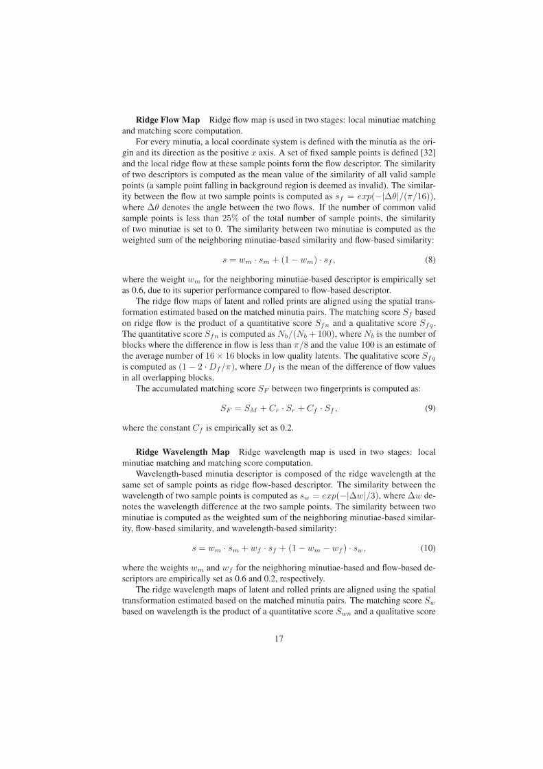
Ridge Flow Map Ridge flow map is used in two stages: local minutiae matching
and matching score computation.
For every minutia, a local coordinate system is defined with the minutia as the ori-
gin and its direction as the positive x axis. A set of fixed sample points is defined [32]
and the local ridge flow at these sample points form the flow descriptor. The similarity
of two descriptors is computed as the mean value of the similarity of all valid sample
points (a sample point falling in background region is deemed as invalid). The similar-
ity between the flow at two sample points is computed as sf = exp(−|Δθ|/(π/16)),where Δθ denotes the angle between the two flows. If the number of common valid
sample points is less than 25% of the total number of sample points, the similarity
of two minutiae is set to 0. The similarity between two minutiae is computed as the
weighted sum of the neighboring minutiae-based similarity and flow-based similarity:
s = wm · sm + (1− wm) · sf , (8)
where the weight wm for the neighboring minutiae-based descriptor is empirically set
as 0.6, due to its superior performance compared to flow-based descriptor.
The ridge flow maps of latent and rolled prints are aligned using the spatial trans-
formation estimated based on the matched minutia pairs. The matching score Sf based
on ridge flow is the product of a quantitative score Sfn and a qualitative score Sfq .
The quantitative score Sfn is computed as Nb/(Nb +100), where Nb is the number of
blocks where the difference in flow is less than π/8 and the value 100 is an estimate of
the average number of 16× 16 blocks in low quality latents. The qualitative score Sfq
is computed as (1− 2 ·Df/π), where Df is the mean of the difference of flow values
in all overlapping blocks.
The accumulated matching score SF between two fingerprints is computed as:
SF = SM + Cr · Sr + Cf · Sf , (9)
where the constant Cf is empirically set as 0.2.
Ridge Wavelength Map Ridge wavelength map is used in two stages: local
minutiae matching and matching score computation.
Wavelength-based minutia descriptor is composed of the ridge wavelength at the
same set of sample points as ridge flow-based descriptor. The similarity between the
wavelength of two sample points is computed as sw = exp(−|Δw|/3), where Δw de-
notes the wavelength difference at the two sample points. The similarity between two
minutiae is computed as the weighted sum of the neighboring minutiae-based similar-
ity, flow-based similarity, and wavelength-based similarity:
s = wm · sm + wf · sf + (1− wm − wf ) · sw, (10)
where the weights wm and wf for the neigbhoring minutiae-based and flow-based de-
scriptors are empirically set as 0.6 and 0.2, respectively.
The ridge wavelength maps of latent and rolled prints are aligned using the spatial
transformation estimated based on the matched minutia pairs. The matching score Sw
based on wavelength is the product of a quantitative score Swn and a qualitative score
17

Swq . The quantitative score Swn is computed as Nb/(Nb + 100), where Nb is the
number of blocks where the difference in wavelength is less than 3 pixels and the value
100 is an estimate of the average number of 16 × 16 blocks in low quality latents.
The qualitative score Swq is computed as the average similarity of wavelength in all
overlapping blocks.
The accumulated matching score SW between two fingerprints is computed as:
SW = SM + Cr · Sr + Cf · Sf + Cw · Sw, (11)
where the constant Cw is empirically set as 0.2.
Skeleton Minutiae can be deemed as an abstract representation of ridge skeleton.
However, the skeleton image contains more information than minutiae. The skeleton
matching algorithm is similar in spirit to the “ridges in sequence” idea recommended
by SWGFAST [50]. Hara and Toyama [25] describe an interesting skeleton matching
algorithm, which consists of the following steps: 1) select the most reliable minutiae
pair from all the matched minutiae pairs as the base paired minutiae (BPM); 2) remove
minutiae pairs that are inconsistent with BPM; 3) modify the two skeleton images to
make them more similar; and 4) incrementally match skeleton points guided by the
matched minutiae or skeleton points. While their approach needs at least three pairs
of correctly matched minutiae to guide the skeleton matching process, our approach
needs only a pair of correctly matched minutiae as starting point, which is useful in
matching latent prints with very small area.
The proposed skeleton matching algorithm is an improved version of the algorithm
in [37]. Its main steps are briefly described as follows.
1. Similarity between minutiae of two fingerprints is computed.
2. For each of the five most similar minutiae pairs, steps 3 to 5 are performed to
establish correspondence between skeletons of two fingerprints and compute a
matching score. The maximum value of these scores is used as the skeleton
matching score.
3. The associated skeletons of the initial minutiae pair are assumed to be matched
and used as a reference.
4. Skeletons adjacent to reference skeleton pair are aligned according to reference
skeleton pair and then matched. Newly matched skeletons are used a new refer-
ence. This step is iteratively performed until no more skeletons can be matched.
5. A skeleton matching score is computed.
The differences from the algorithm in [37] lie in the computation of minutiae simi-
larity and skeleton matching score. The similarity between minutiae is now computed
using the composite minutiae descriptor based on neighboring minutiae, ridge flow,
and wavelength features. The similarity computation is described in previous subsec-
tions. This composite descriptor is more robust to noise than the ridge structure based
18

descriptor used in [37]. The skeleton matching score is computed as the product of a
quantitative score Ssn and a qualitative score Ssq:
Ss = Ssn · Ssq. (12)
The quantitive score Ssn is computed as:
Ssn =Ms
Ms + 400, (13)
where Ms denotes the number of matched skeleton points and the value 400 is an
estimate of the average number of skeleton sample points in low quality latents. The
qualitative score is computed as:
Ssq =Ms
Ms + ULs
· Ms
M + URs
, (14)
where ULs and UR
s denote the number of unmatched skeleton sample points of latent
and rolled prints in their common region, respectively.
The accumulated matching score SS is obtained by combining Ss and SW com-
puted in Eq. (11):
SS = SW + Cs · Ss, (15)
where the constant Cs is empirically set as 1. For efficiency, skeleton matching is
performed only for the top 100 candidates found by the minutiae matcher.
2.3.2 Level 3
Algorithm Overview Given a latent fingerpint, it is first matched with the exemplars
in the background database by using a minutiae matcher (VeriFinger [44] was used
in our experiments). The rank 1 minutiae match score is then examined to determine
if it is necessary to invoke the level 3 feature matching module. Specifically, if the
rank 1 minutiae match score is already above a prespecified threshold, the matcher will
directly output the identification results (e.g. the list of top N candidates); otherwise,
the level 3 features will be further compared, and the final identification results will be
based on the fusion of the matching results of minutiae and level 3 features. Fig. 11
illustrates this algorithm.
We first match the minutiae because i) minutiae have already been shown to be
stable and discriminative, and ii) minutiae form the basis of all the available AFIS.
In the rest of this section, we will describe the three modules of the proposed level 3
feature matching method, i.e. ridge correspondence establishment, pore matching, and
DIP matching.
Ridge Correspondence Establishment The level 3 feature matching method
proposed here differs from existing methods in that it matches level 3 features along the
ridges and incorporates the topological relationship between level 3 features, minutiae,
and ridges. Given a query latent Fq and an exemplar full fingerprint Ft, the proposed
matcher first establishes the ridge correspondences between the two fingerprints. To
19
facilitate ridge matching process, the ridges in each fingerprint are traced and sam-
pled at a constant interval (in our experiments, the interval is set to 10 pixels, which is
the allowed tolerance of location displacement between two matched level 3 features).
During the ridge tracing and sampling, the associated minutiae (if any) are recorded for
each of the ridges, and the neighboring ridges and the neighboring sampling points on
the left-hand and right-hand sides at each sampling point of the ridge are also recorded.
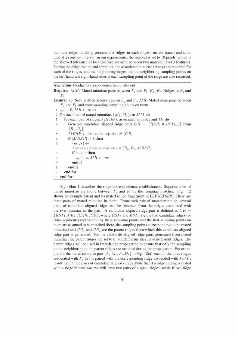
Algorithm 1 Ridge Correspondence Establishment
Require: MM : Mated minutiae pairs between Fq and Ft; Rq , Rt: Ridges in Fq and
Ft
Ensure: sr: Similarity between ridges in Fq and Ft; MR: Mated ridge pairs between
Fq and Ft, and corresponding sampling points on them
1: sr ← 0, MR← NULL2: for each pair of mated minutiae, {M1,M2}, in MM do3: for each pair of ridges, {R1, R2}, associated with M1 and M2 do4: Generate candidate aligned ridge pairs CR = {RSP1, 0, RSP2, 0} from
{R1, R2}5: MRSP ← IntraRidgeMatch(CR)6: if |MRSP | > 4 then7: (mr, s)←
InterRidgePropagation(Rq, Rt,MRSP )8: if sr < s then9: sr ← s, MR← mr
10: end if11: end if12: end for13: end for
Algorithm 1 describes the ridge correspondence establishment. Suppose a set of
mated minutiae are found between Fq and Ft by the minutiae matcher. Fig. 12
shows an example latent and its mated rolled fingerprint in ELFT-EFS-PC. There are
three pairs of mated minutiae in them. From each pair of mated minutiae, several
pairs of candidate aligned ridges can be obtained from the ridges associated with
the two minutiae in the pair. A candidate aligned ridge pair is defined as CR ={RSP1, PR1;RSP2, PR2}, where RSP1 and RSP2 are the two candidate ridges (or
ridge segments) represented by their sampling points and the first sampling points on
them are assumed to be matched (here, the sampling points corresponding to the mated
minutiae) and PR1 and PR2 are the parent ridges from which this candidate aligned
ridge pair is generated. For the candidate aligned ridge pairs generated from mated
minutiae, the parent ridges are set to 0, which means they have no parent ridges. The
parent ridges will be used in Inter-Ridge propagation to ensure that only the sampling
points neighboring to the parent ridges are matched during the propagation. For exam-
ple, for the mated minutiae pair {Fq.M1, Ft.M1} in Fig. 12(a), each of the three ridges
associated with Fq.M1 is paired with the corresponding ridge associated with Ft.M1,
resulting in three pairs of candidate aligned ridges. Note that if a ridge ending is mated
with a ridge bifurcation, we will have two pairs of aligned ridges, while if two ridge
20
endings are mated, we will get only one pair of aligned ridges.
From each of these aligned ridge pairs, the two ridges in the pair are first compared
by the Intra-Ridge matching procedure. If the two ridges can be matched (i.e. more
than four sampling points are matched between them), the Inter-Ridge propagation
procedure is invoked to match the remaining ridges in the two fingerprints based on
the mated sampling points on the two ridges. After all the aligned ridge pairs have
been considered, the ridge correspondences obtained from the one which gives the
highest similarity between the ridges in the two fingerprints are taken as the final result.
Next, we introduce the two main procedures, Intra-Ridge matching and Inter-Ridge
propagation, involved in ridge correspondence establishment.
Given a candidate aligned ridge pair CR = {RSP1, PR1, RSP2, PR2}, Intra-
Ridge matching is used to find the corresponding sampling points on the two aligned
ridges (or ridge segments). This is essentially a string matching problem given that the
first sampling points in RSP1 and RSP2 are matched. We employ the dynamic pro-
gramming technique [37] to find the longest sequence of mated sampling points on the
two ridges, MRSP = {RSPm1 , RSPm
2 }, such that (i) the indices of mated sampling
points monotonously increase in both RSPm1 and RSPm
2 , (ii) changes between indices
of adjacent mated sampling points are less than 3 (i.e. no more than 3 sampling points
can be skipped during matching), and (iii) if PRi �= 0, all the mated sampling points
in RSPmi should have PRi as their neighboring ridges (i = 1, 2). In our implemen-
tation, two mated sampling points should satisfy i) the absolute difference between the
distances from them to the first sampling points is below a given threshold (i.e. 10 pix-
els), and ii) the absolute difference between the ridge curvatures at them is also below
a given threshold (i.e. 15 degrees). We measure the distance between two sampling
points on a ridge by using the absolute difference between their indices, which is sim-
ilar to geodesic distance. The ridge curvature at a sampling point is measured by the
change in local ridge orientation at the point with respect to the ridge orientation at the
first sampling point.
Given the mated points between two ridges, the similarity between the ridges is
computed as follows. Because short ridges are mostly unreliable, if there are fewer than
4 mated points between two ridges, we discard them. Otherwise, we further examine
the neighboring ridge structures of the mated sampling points. Let nmsp = |MRSP |be the number of mated sampling points found on RSP1 and RSP2. For all the mated
sampling points in RSPmi (i = 1, 2), we examine on left-hand and right-hand sides,
repsectively, if the neighboring ridges of each two adjacent sampling points are dif-
ferent or not, resulting in two feature vectors, NRli ∈ {0, 1}nmsp−1 and NRr
i ∈{0, 1}nmsp−1, in which ‘0’ means same ridge and ‘1’ means different ridges. NRl
1
and NRr1 are then compared with NRl
2 and NRr2, respectively, and the number of the
same entries between them is counted, denoted as nlNR and nr
NR for the left-hand and
right-hand sides, respectively. The similarity between the neighboring ridge structures
of the mated sampling points on the two ridges is then calculated by
sN = 0.5× nlNR
nmsp − 1+ 0.5× nr
NR
nmsp − 1. (16)
If the mated sampling points on the two ridges have very low similarity between their
neighboring ridge structures, they are also discarded. Fig. 12(b) shows the Intra-Ridge
21
matching results for the ridges Fq.R1 and Ft.R1 associated with the mated minutiae
Fq.M1 and Ft.M1 in Fig. 12(a).
Given a set of mated sampling points on the two ridges found by the Intra-Ridge
matching procedure, the Inter-Ridge propagation procedure, as sketched in Algorithm
2, matches all the remaining ridges. A queue (denoted as Q) is constructed to store the
candidate aligned ridge pairs. The queue is initialized by generating candidate aligned
ridge pairs from each pair of mated sampling points. The candidate aligned ridge pairs
are the neighboring ridges on the corresponding sides of the mated sampling points.
After the initialization of Q, we start the main loop of the Inter-Ridge propagation
procedure to compare the ridges in each of the candidate aligned ridge pairs in Q until
Q is empty. The first candidate in Q is popped out and matched by the Intra-Ridge
matching procedure. If more than four mated sampling points are established, new
candidate aligned ridge pairs are generated and pushed into Q. When Q is empty, the
Inter-Ridge propagation procedure terminates with a set of mated ridge pairs as well
as the corresponding mated sampling points. Figs. 12(c) and 12(d) shows the mated
ridge pairs found between the two example fingerprints as the procedure Inter-Ridge
propagation proceeds from the mated ridge pairs shown in Fig. 12(b).
Let sN , dloc, and dori be the average similarity between neighboring ridge struc-
tures of all the mated ridge pairs, the average location displacement and the average
orientation difference between all the mated sampling points, respectively. Let nMRSP
and nRSP denote the total number of mated sampling points on the ridges in the two
fingerprints and the total number of sampling points on ridges in the query fingerprint,
respectively. Then the similarity between the ridges in the two fingerprints is defined
as
sr = 0.3× sN + 0.2× 10− dloc10
+ 0.2× 15− dori15
+ 0.3× nMRSP
nRSP. (17)
Pore Matching Once the correspondences between ridges are obtained, the level
3 features can be matched along the mated ridges. To implement this, we need to first
associate the level 3 features with the ridges. In this section we discuss the matching
of pores; the matching of DIP features will be discussed in the next section. Recall that
pores in a fingerprint are all located on ridges. Hence, for each pore, we find the closest
ridge to it and its projection point on this ridge. The pores on the same ridge are then
grouped together and ordered along the ridge tracing direction.
Given a pair of mated ridges, the correspondences between pores on these two
ridges are found using the following method. For each pore on a ridge, POR1, we
first find its closest sampling point SP1 on the ridge (denote the ridge as R1). If SP1
does not have a mated sampling point, then POR1 does not have any mated pores;
otherwise, we find the nearest pore, POR2, to the mated sampling point, SP2, of SP1.
The location displacement di between PORi and SPi (i = 1, 2) is calculated as the
difference between the sampling indices of the projection point of PORi and SPi.
The location displacement between the two pores, POR1 and POR2, is then defined
22

Algorithm 2 Inter-Ridge Propagation
Require: MRSP : Mated sampling points on two ridges in Fq and Ft; Rq , Rt: Ridges
in Fq and Ft
Ensure: sr: Similarity between ridges in Fq and Ft; MR: Mated ridge pairs between
Fq and Ft, and corresponding sampling points on them
1: MR←MRSP2: Initialize the queue of candidate aligned ridge pairs, Q, based on MRSP
3: while Q is not empty do4: Retrieve the first candidate aligned ridge pair in Q: CR5: mrsp← IntraRidgeMatch(CR)6: if |mrsp| > 4 then7: Append mrsp to MR8: Generate new candidate aligned ridge pairs based on mrsp9: Push the new candidate aligned ridge pairs into Q
10: end if11: end while12: Calculate the similarity between the ridges in Fq and Ft: sr
as dloc = |d1 − d2|. If dloc is smaller than a given threshold (i.e. 10 pixels for 1000ppi
fingerprint images), POR1 is mated with POR2. After all the pores in the latent are
examined, we get the mated pores between the two fingerprints. Fig. 13(a) shows the
mated pores obtained between a latent and its mated exemplar.
To calculate the pore match score, we compare the neighboring ridge structures
and pore distribution of the mated pores on each pair of mated ridges (recall that the
pores on a ridge are ordered, so are the mated pores). A comparison of neighboring
ridge structures is the same as being described for mated sampling points on ridges. As
for the neighboring pore distribution, if two mated pores both have a neighboring pore
on its left-hand side or right-hand side neighboring ridge, the location displacement
between the neighboring pores is calculated. Let dl,iNP be the location displacement
between the neighboring pores on the left-hand side of the ith mated pores on the
mated ridges, and dr,iNP the location displacement between the neighboring pores on
the right-hand side of them. The similarity between the neighboring ridge structures
and pore distribution of the mated pores in the two ridges can be then calculated as
sN = 0.4× nlNR
nmp − 1+ 0.4× nr
NR
nmp − 1
+ 0.1× ΣnlNP
i=1 (10− dl,iNP )
10× nlNP
+ 0.1× ΣnrNP
i=1 (10− dr,iNP )
10× nrNP
, (18)
where nmp is the number of mated pores on the two ridges and nlNP and nr
NP are
the number of cooccurring neighboring pores on the left-hand and right-hand sides,
23
respectively. Finally, the pore match score between the two fingerprints is defined as
sPOR = 0.8 × sr + 0.2 × (0.3 × sN + 0.3 × 10− dloc10
+ 0.4 × nMP
nP), (19)
where sN is the average similarity between neighboring ridge structures and pore dis-
tribution of all the mated pores on the mated ridge pairs, dloc is the average location
displacement between all the mated pores, and nMP and nP denote the total number
of mated pores and the number of pores in the query latent fingerprint, respectively. It
is worth mentioning that the above match score measures the similarity between fin-
gerprints by considering not only the location displacement between mated pores and
the number of mated pores, but also the consistency of the ridge structures and feature
distribution surrounding the mated pores, whereas existing methods [35, 54] consider
only the location displacement or the number of mated pores.
DIP Matching The matching of DIP features is also constrained along mated
ridges. Unlike pores, DIP features reside on valleys rather than ridges. Therefore, we
associate each DIP feature with two ridges that are on the left-hand and right-hand sides
of the valley on which it resides. Given a DIP feature DIP1 which is associated with
two ridges R11 and R12, the nearest sampling point to its projection on the ridge R11 is
first found, denoted as SP1. If SP1 does not have mated sampling points, then DIP1
does not have mated DIP features; otherwise, the nearest DIP feature to the mated
sampling point SP2 on the mated ridge R21 of R11 is found, denoted as DIP2. Let
di be the location displacement between DIPi and SPi (i = 1, 2), then the location
displacement between DIP1 and DIP2 is dloc = |d1− d2|. Let R22 be the other ridge
associated with DIP2. DIP1 and DIP2 are mated DIP features only if i) dloc ≤ 10and ii) R12 and R22 are mated ridges. After enumerating all the DIP features in Fq , we
obtain the mated DIP features. Fig. 13(b) shows the mated DIP features in a latent and
its mated exemplar.
Let dloc be the average location displacement between all the mated DIP features
and nMDIP and nDIP be the total number of mated DIP features and the number of
DIP features in the query latent fingerprint, respectively. The DIP match score between
the two fingerprints is then defined as
sDIP = 0.8 × sr + 0.2 × (0.3 × 10− dloc10
+ 0.7 × nMDIP
nDIP). (20)
24
3 Results
3.1 Statement of results3.1.1 Level 1 and Level 2
Database To evaluate the latent fingerprint matching algorithm, 258 latent finger-
prints in NIST SD27, which also contains the mated rolled prints, were matched against
a large background database of rolled prints. This is the only public domain database
available containing mated latent and rolled prints. Since there are only 257 (excluding
one duplicate image) rolled fingerprints in SD27, to make the latent-to-rolled match-
ing problem more realistic, we expand the background database by adding fingerprints
from NIST SD4 and SD14 databases. There are 2,000 different fingers and 2 rolled
impressions per finger in SD4, and 27,000 fingers and 2 rolled impressions per finger
in SD14. These fingerprints were also scanned from paper and have similar character-
istics to the rolled prints in SD27. The 29,000 file fingerprints in SD4 and SD14 are
combined with the 257 rolled images in SD27 to form a background database contain-
ing 29,257 rolled prints. We search the 258 latents against this background database of
29,257 rolled prints. All these fingerprint images are scanned at 500 ppi.
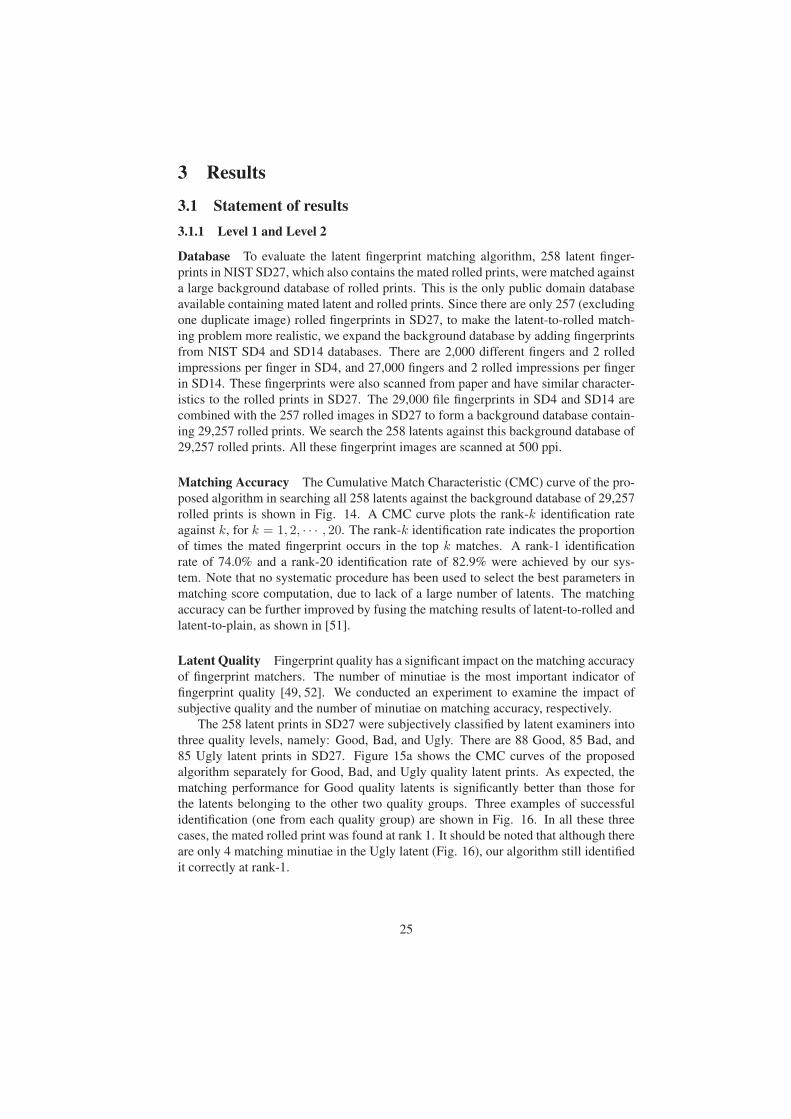
Matching Accuracy The Cumulative Match Characteristic (CMC) curve of the pro-
posed algorithm in searching all 258 latents against the background database of 29,257
rolled prints is shown in Fig. 14. A CMC curve plots the rank-k identification rate
against k, for k = 1, 2, · · · , 20. The rank-k identification rate indicates the proportion
of times the mated fingerprint occurs in the top k matches. A rank-1 identification
rate of 74.0% and a rank-20 identification rate of 82.9% were achieved by our sys-
tem. Note that no systematic procedure has been used to select the best parameters in
matching score computation, due to lack of a large number of latents. The matching
accuracy can be further improved by fusing the matching results of latent-to-rolled and
latent-to-plain, as shown in [51].
Latent Quality Fingerprint quality has a significant impact on the matching accuracy
of fingerprint matchers. The number of minutiae is the most important indicator of
fingerprint quality [49, 52]. We conducted an experiment to examine the impact of
subjective quality and the number of minutiae on matching accuracy, respectively.
The 258 latent prints in SD27 were subjectively classified by latent examiners into
three quality levels, namely: Good, Bad, and Ugly. There are 88 Good, 85 Bad, and
85 Ugly latent prints in SD27. Figure 15a shows the CMC curves of the proposed
algorithm separately for Good, Bad, and Ugly quality latent prints. As expected, the
matching performance for Good quality latents is significantly better than those for
the latents belonging to the other two quality groups. Three examples of successful
identification (one from each quality group) are shown in Fig. 16. In all these three
cases, the mated rolled print was found at rank 1. It should be noted that although there
are only 4 matching minutiae in the Ugly latent (Fig. 16), our algorithm still identified
it correctly at rank-1.
25
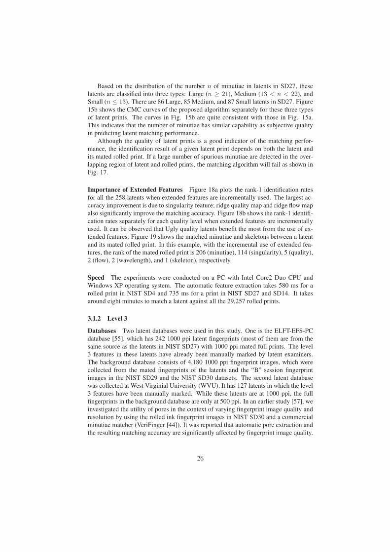
Based on the distribution of the number n of minutiae in latents in SD27, these
latents are classified into three types: Large (n ≥ 21), Medium (13 < n < 22), and
Small (n ≤ 13). There are 86 Large, 85 Medium, and 87 Small latents in SD27. Figure
15b shows the CMC curves of the proposed algorithm separately for these three types
of latent prints. The curves in Fig. 15b are quite consistent with those in Fig. 15a.
This indicates that the number of minutiae has similar capability as subjective quality
in predicting latent matching performance.
Although the quality of latent prints is a good indicator of the matching perfor-
mance, the identification result of a given latent print depends on both the latent and
its mated rolled print. If a large number of spurious minutiae are detected in the over-
lapping region of latent and rolled prints, the matching algorithm will fail as shown in
Fig. 17.
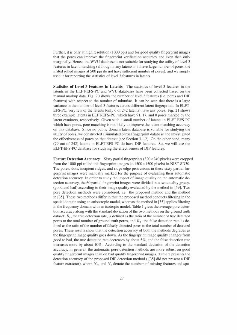
Importance of Extended Features Figure 18a plots the rank-1 identification rates
for all the 258 latents when extended features are incrementally used. The largest ac-
curacy improvement is due to singularity feature; ridge quality map and ridge flow map
also significantly improve the matching accuracy. Figure 18b shows the rank-1 identifi-
cation rates separately for each quality level when extended features are incrementally
used. It can be observed that Ugly quality latents benefit the most from the use of ex-
tended features. Figure 19 shows the matched minutiae and skeletons between a latent
and its mated rolled print. In this example, with the incremental use of extended fea-
tures, the rank of the mated rolled print is 206 (minutiae), 114 (singularity), 5 (quality),
2 (flow), 2 (wavelength), and 1 (skeleton), respectively.
Speed The experiments were conducted on a PC with Intel Core2 Duo CPU and
Windows XP operating system. The automatic feature extraction takes 580 ms for a
rolled print in NIST SD4 and 735 ms for a print in NIST SD27 and SD14. It takes
around eight minutes to match a latent against all the 29,257 rolled prints.
3.1.2 Level 3
Databases Two latent databases were used in this study. One is the ELFT-EFS-PC
database [55], which has 242 1000 ppi latent fingerprints (most of them are from the
same source as the latents in NIST SD27) with 1000 ppi mated full prints. The level
3 features in these latents have already been manually marked by latent examiners.
The background database consists of 4,180 1000 ppi fingerprint images, which were
collected from the mated fingerprints of the latents and the “B” session fingerprint
images in the NIST SD29 and the NIST SD30 datasets. The second latent database
was collected at West Virginial University (WVU). It has 127 latents in which the level
3 features have been manually marked. While these latents are at 1000 ppi, the full
fingerprints in the background database are only at 500 ppi. In an earlier study [57], we
investigated the utility of pores in the context of varying fingerprint image quality and
resolution by using the rolled ink fingerprint images in NIST SD30 and a commercial
minutiae matcher (VeriFinger [44]). It was reported that automatic pore extraction and
the resulting matching accuracy are significantly affected by fingerprint image quality.
26
Further, it is only at high resolution (1000 ppi) and for good quality fingerprint images
that the pores can improve the fingerprint verification accuracy and even then only
marginally. Hence, the WVU database is not suitable for studying the utility of level 3
features in latent matching (although many latents in it have large number of pores, the
mated rolled images at 500 ppi do not have sufficient number of pores), and we simply
used it for reporting the statistics of level 3 features in latents.
Statistics of Level 3 Features in Latents The statistics of level 3 features in the
latents in the ELFT-EFS-PC and WVU databases have been collected based on the
manual markup data. Fig. 20 shows the number of level 3 features (i.e. pores and DIP
features) with respect to the number of minutiae. It can be seen that there is a large
variance in the number of level 3 features across different latent fingerprints. In ELFT-
EFS-PC, very few of the latents (only 6 of 242 latents) have any pores. Fig. 21 shows
three example latents in ELFT-EFS-PC, which have 91, 17, and 0 pores marked by the
latent exminers, respectively. Given such a small number of latents in ELFT-EFS-PC
which have pores, pore matching is not likely to improve the latent matching accuracy
on this database. Since no public domain latent database is suitable for studying the
utility of pores, we constructed a simulated partial fingerprint database and investigated
the effectiveness of pores on that dataset (see Section 3.1.2). On the other hand, many
(79 out of 242) latents in ELFT-EFS-PC do have DIP features. So, we will use the
ELFT-EFS-PC database for studying the effectiveness of DIP features.
Feature Detection Accuracy Sixty partial fingerprints (320×240 pixels) were cropped
from the 1000 ppi rolled ink fingerprint images (∼1500×1500 pixels) in NIST SD30.
The pores, dots, incipient ridges, and ridge edge protrusions in these sixty partial fin-
gerprint images were manually marked for the purpose of evaluating their automatic
detection accuracy. In order to study the impact of image quality on the automatic de-
tection accuracy, the 60 partial fingerprint images were divided into two quality groups
(good and bad) according to their image quality evaluated by the method in [59]. Two
pore detection methods were considered, i.e. the proposed method and the method
in [35]. These two methods differ in that the proposed method conducts filtering in the
spatial domain using an anisotropic model, whereas the method in [35] applies filtering
in the frequency domain with an isotropic model. Table 1 gives the average pore detec-
tion accuracy along with the standard deviation of the two methods on the ground truth
dataset; Rt, the true detection rate, is defined as the ratio of the number of true detected
pores to the total number of ground truth pores, and Rf , the false detection rate, is de-
fined as the ratio of the number of falsely detected pores to the total number of detected
pores. These results show that the detection accuracy of both the methods degrades as
the fingerprint image quality goes down. As the fingerprint image quality changes from
good to bad, the true detection rate decreases by about 5%, and the false detection rate
increases more by about 10%. According to the standard deviation of the detection
accuracy, in general, the automatic pore detection methods are more robust on good
quality fingerprint images than on bad quality fingerprint images. Table 2 presents the
detection accuracy of the proposed DIP detection method ( [35] did not present a DIP
feature extractor), where Nm and Ns denote the numbers of missing features and spu-
27
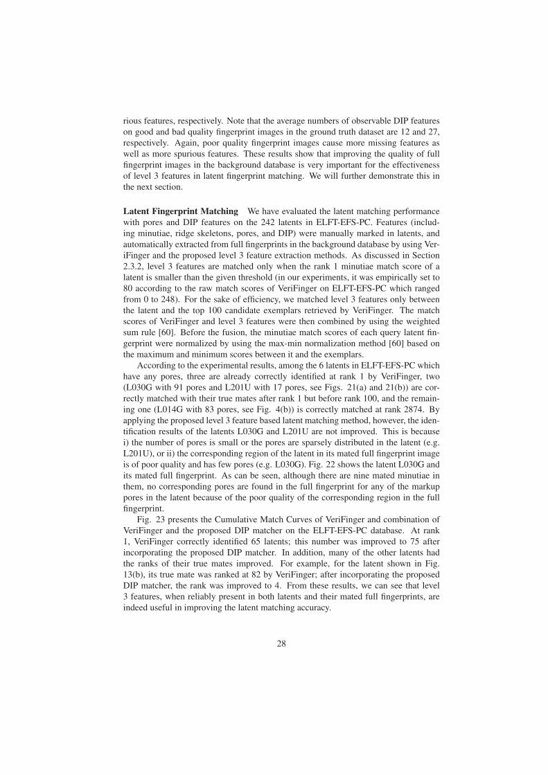
rious features, respectively. Note that the average numbers of observable DIP features
on good and bad quality fingerprint images in the ground truth dataset are 12 and 27,
respectively. Again, poor quality fingerprint images cause more missing features as
well as more spurious features. These results show that improving the quality of full
fingerprint images in the background database is very important for the effectiveness
of level 3 features in latent fingerprint matching. We will further demonstrate this in
the next section.
Latent Fingerprint Matching We have evaluated the latent matching performance
with pores and DIP features on the 242 latents in ELFT-EFS-PC. Features (includ-
ing minutiae, ridge skeletons, pores, and DIP) were manually marked in latents, and
automatically extracted from full fingerprints in the background database by using Ver-
iFinger and the proposed level 3 feature extraction methods. As discussed in Section
2.3.2, level 3 features are matched only when the rank 1 minutiae match score of a
latent is smaller than the given threshold (in our experiments, it was empirically set to
80 according to the raw match scores of VeriFinger on ELFT-EFS-PC which ranged
from 0 to 248). For the sake of efficiency, we matched level 3 features only between
the latent and the top 100 candidate exemplars retrieved by VeriFinger. The match
scores of VeriFinger and level 3 features were then combined by using the weighted
sum rule [60]. Before the fusion, the minutiae match scores of each query latent fin-
gerprint were normalized by using the max-min normalization method [60] based on
the maximum and minimum scores between it and the exemplars.
According to the experimental results, among the 6 latents in ELFT-EFS-PC which
have any pores, three are already correctly identified at rank 1 by VeriFinger, two
(L030G with 91 pores and L201U with 17 pores, see Figs. 21(a) and 21(b)) are cor-
rectly matched with their true mates after rank 1 but before rank 100, and the remain-
ing one (L014G with 83 pores, see Fig. 4(b)) is correctly matched at rank 2874. By
applying the proposed level 3 feature based latent matching method, however, the iden-
tification results of the latents L030G and L201U are not improved. This is because
i) the number of pores is small or the pores are sparsely distributed in the latent (e.g.
L201U), or ii) the corresponding region of the latent in its mated full fingerprint image
is of poor quality and has few pores (e.g. L030G). Fig. 22 shows the latent L030G and
its mated full fingerprint. As can be seen, although there are nine mated minutiae in
them, no corresponding pores are found in the full fingerprint for any of the markup
pores in the latent because of the poor quality of the corresponding region in the full
fingerprint.
Fig. 23 presents the Cumulative Match Curves of VeriFinger and combination of
VeriFinger and the proposed DIP matcher on the ELFT-EFS-PC database. At rank
1, VeriFinger correctly identified 65 latents; this number was improved to 75 after
incorporating the proposed DIP matcher. In addition, many of the other latents had
the ranks of their true mates improved. For example, for the latent shown in Fig.
13(b), its true mate was ranked at 82 by VeriFinger; after incorporating the proposed
DIP matcher, the rank was improved to 4. From these results, we can see that level
3 features, when reliably present in both latents and their mated full fingerprints, are
indeed useful in improving the latent matching accuracy.
28
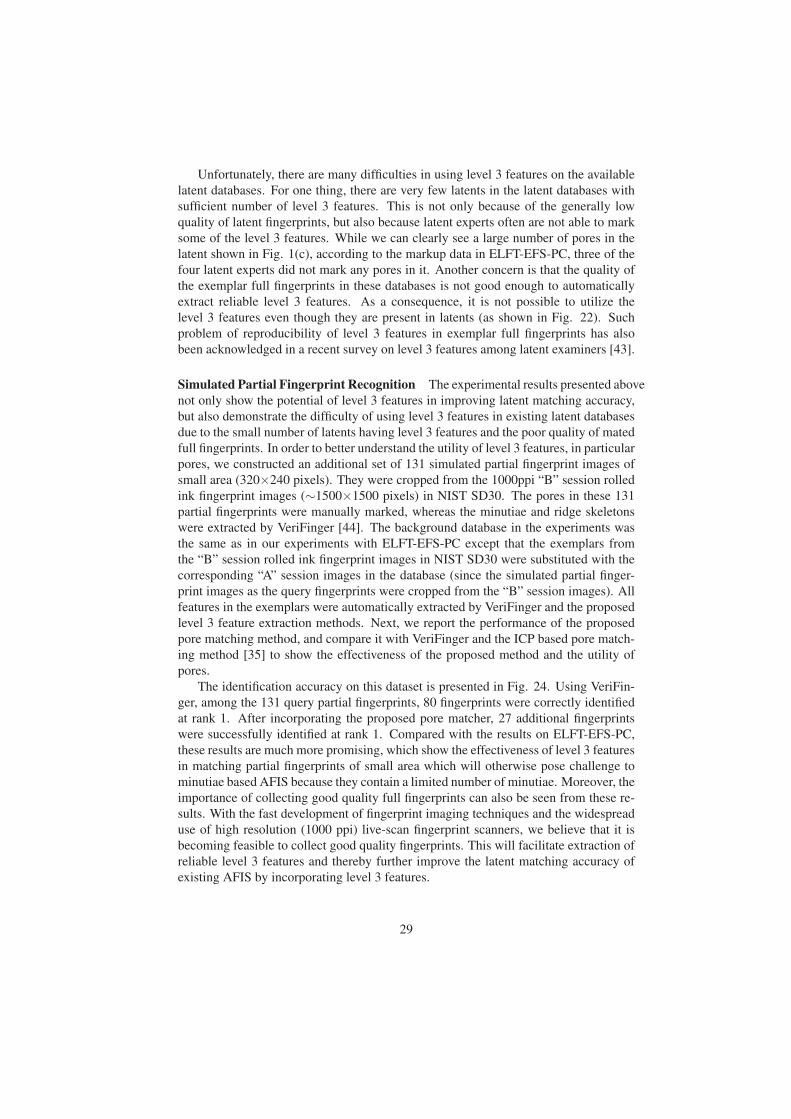
Unfortunately, there are many difficulties in using level 3 features on the available
latent databases. For one thing, there are very few latents in the latent databases with
sufficient number of level 3 features. This is not only because of the generally low
quality of latent fingerprints, but also because latent experts often are not able to mark
some of the level 3 features. While we can clearly see a large number of pores in the
latent shown in Fig. 1(c), according to the markup data in ELFT-EFS-PC, three of the
four latent experts did not mark any pores in it. Another concern is that the quality of
the exemplar full fingerprints in these databases is not good enough to automatically
extract reliable level 3 features. As a consequence, it is not possible to utilize the
level 3 features even though they are present in latents (as shown in Fig. 22). Such
problem of reproducibility of level 3 features in exemplar full fingerprints has also
been acknowledged in a recent survey on level 3 features among latent examiners [43].
Simulated Partial Fingerprint Recognition The experimental results presented above
not only show the potential of level 3 features in improving latent matching accuracy,
but also demonstrate the difficulty of using level 3 features in existing latent databases
due to the small number of latents having level 3 features and the poor quality of mated
full fingerprints. In order to better understand the utility of level 3 features, in particular
pores, we constructed an additional set of 131 simulated partial fingerprint images of
small area (320×240 pixels). They were cropped from the 1000ppi “B” session rolled
ink fingerprint images (∼1500×1500 pixels) in NIST SD30. The pores in these 131
partial fingerprints were manually marked, whereas the minutiae and ridge skeletons
were extracted by VeriFinger [44]. The background database in the experiments was
the same as in our experiments with ELFT-EFS-PC except that the exemplars from
the “B” session rolled ink fingerprint images in NIST SD30 were substituted with the
corresponding “A” session images in the database (since the simulated partial finger-
print images as the query fingerprints were cropped from the “B” session images). All
features in the exemplars were automatically extracted by VeriFinger and the proposed
level 3 feature extraction methods. Next, we report the performance of the proposed
pore matching method, and compare it with VeriFinger and the ICP based pore match-
ing method [35] to show the effectiveness of the proposed method and the utility of
pores.
The identification accuracy on this dataset is presented in Fig. 24. Using VeriFin-
ger, among the 131 query partial fingerprints, 80 fingerprints were correctly identified
at rank 1. After incorporating the proposed pore matcher, 27 additional fingerprints
were successfully identified at rank 1. Compared with the results on ELFT-EFS-PC,
these results are much more promising, which show the effectiveness of level 3 features
in matching partial fingerprints of small area which will otherwise pose challenge to
minutiae based AFIS because they contain a limited number of minutiae. Moreover, the
importance of collecting good quality full fingerprints can also be seen from these re-
sults. With the fast development of fingerprint imaging techniques and the widespread
use of high resolution (1000 ppi) live-scan fingerprint scanners, we believe that it is
becoming feasible to collect good quality fingerprints. This will facilitate extraction of
reliable level 3 features and thereby further improve the latent matching accuracy of
existing AFIS by incorporating level 3 features.
29
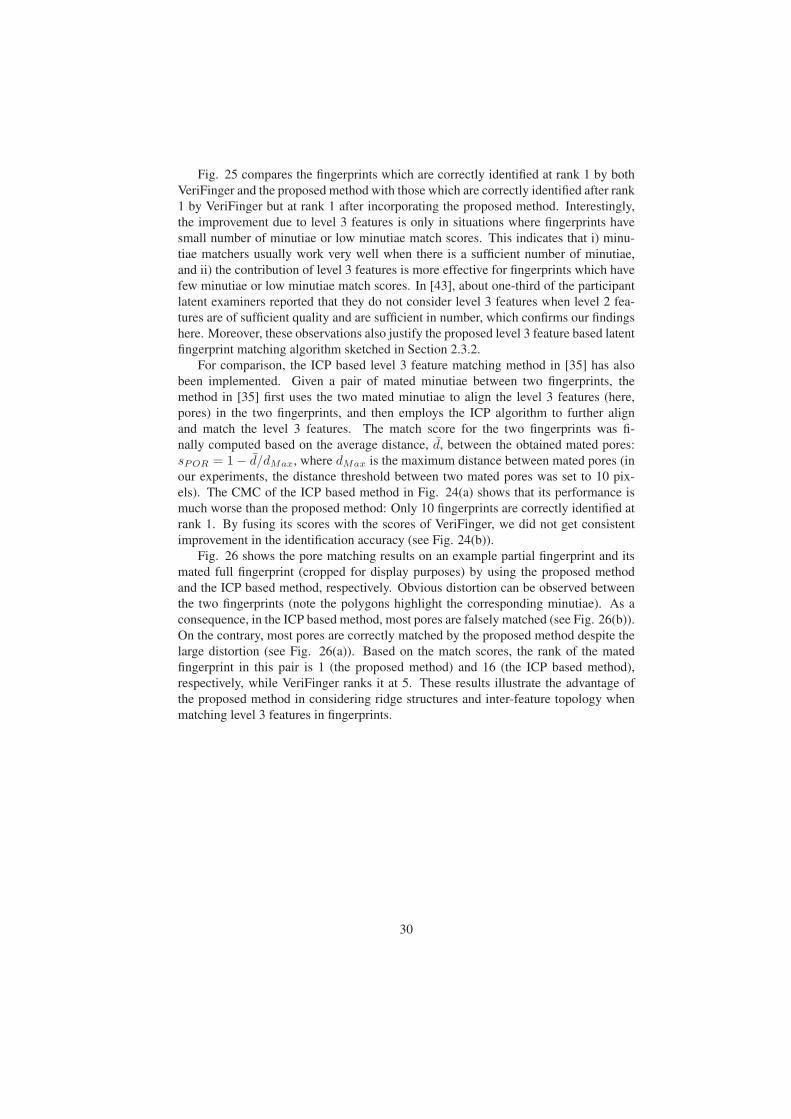
Fig. 25 compares the fingerprints which are correctly identified at rank 1 by both
VeriFinger and the proposed method with those which are correctly identified after rank
1 by VeriFinger but at rank 1 after incorporating the proposed method. Interestingly,
the improvement due to level 3 features is only in situations where fingerprints have
small number of minutiae or low minutiae match scores. This indicates that i) minu-
tiae matchers usually work very well when there is a sufficient number of minutiae,
and ii) the contribution of level 3 features is more effective for fingerprints which have
few minutiae or low minutiae match scores. In [43], about one-third of the participant
latent examiners reported that they do not consider level 3 features when level 2 fea-
tures are of sufficient quality and are sufficient in number, which confirms our findings
here. Moreover, these observations also justify the proposed level 3 feature based latent
fingerprint matching algorithm sketched in Section 2.3.2.
For comparison, the ICP based level 3 feature matching method in [35] has also
been implemented. Given a pair of mated minutiae between two fingerprints, the
method in [35] first uses the two mated minutiae to align the level 3 features (here,
pores) in the two fingerprints, and then employs the ICP algorithm to further align
and match the level 3 features. The match score for the two fingerprints was fi-
nally computed based on the average distance, d, between the obtained mated pores:
sPOR = 1− d/dMax, where dMax is the maximum distance between mated pores (in
our experiments, the distance threshold between two mated pores was set to 10 pix-
els). The CMC of the ICP based method in Fig. 24(a) shows that its performance is
much worse than the proposed method: Only 10 fingerprints are correctly identified at
rank 1. By fusing its scores with the scores of VeriFinger, we did not get consistent
improvement in the identification accuracy (see Fig. 24(b)).
Fig. 26 shows the pore matching results on an example partial fingerprint and its
mated full fingerprint (cropped for display purposes) by using the proposed method
and the ICP based method, respectively. Obvious distortion can be observed between
the two fingerprints (note the polygons highlight the corresponding minutiae). As a
consequence, in the ICP based method, most pores are falsely matched (see Fig. 26(b)).
On the contrary, most pores are correctly matched by the proposed method despite the
large distortion (see Fig. 26(a)). Based on the match scores, the rank of the mated
fingerprint in this pair is 1 (the proposed method) and 16 (the ICP based method),
respectively, while VeriFinger ranks it at 5. These results illustrate the advantage of
the proposed method in considering ridge structures and inter-feature topology when
matching level 3 features in fingerprints.
30

3.2 Tables
Table 1: Average pore detection accuracy and standard deviation
Method Proposed Method in [35]
Quality Good Bad Good Bad
Rt(%) 73± 9.5 67± 14.6 69± 16.0 63± 12.5Rf (%) 20± 12.2 30± 14.4 27± 11.7 40± 18.1
Table 2: Average DIP detection accuracy and standard deviation
Quality Good Bad
Nm 6± 5.6 12± 8.5Ns 4± 3.6 10± 7.0
31
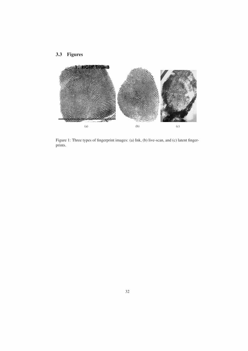
3.3 Figures
(a) (b) (c)
Figure 1: Three types of fingerprint images: (a) Ink, (b) live-scan, and (c) latent finger-
prints.
32
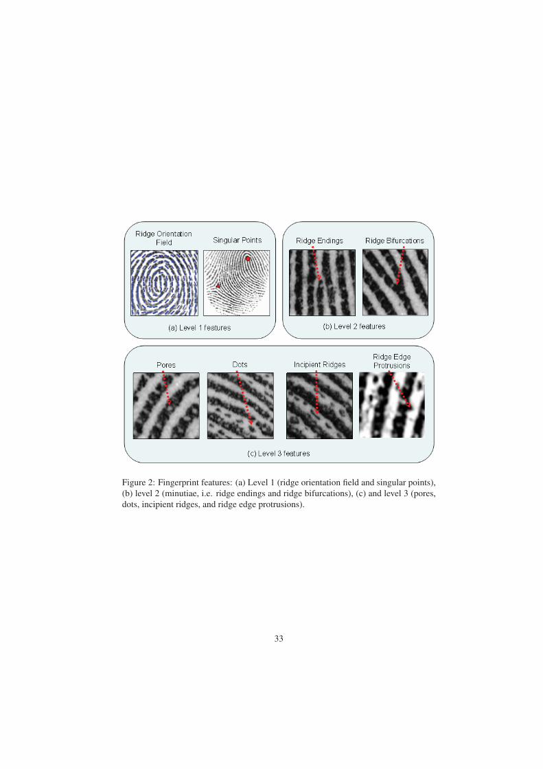
Figure 2: Fingerprint features: (a) Level 1 (ridge orientation field and singular points),
(b) level 2 (minutiae, i.e. ridge endings and ridge bifurcations), (c) and level 3 (pores,
dots, incipient ridges, and ridge edge protrusions).
33
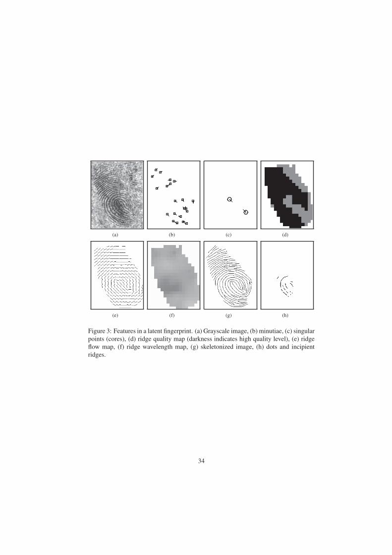
(a) (b) (c) (d)
(e) (f) (g) (h)
Figure 3: Features in a latent fingerprint. (a) Grayscale image, (b) minutiae, (c) singular
points (cores), (d) ridge quality map (darkness indicates high quality level), (e) ridge
flow map, (f) ridge wavelength map, (g) skeletonized image, (h) dots and incipient
ridges.
34
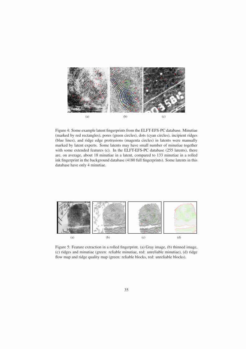
(a) (b) (c)
Figure 4: Some example latent fingerprints from the ELFT-EFS-PC database. Minutiae
(marked by red rectangles), pores (green circles), dots (cyan circles), incipient ridges
(blue lines), and ridge edge protrusions (magenta circles) in latents were manually
marked by latent experts. Some latents may have small number of minutiae together
with some extended features (c). In the ELFT-EFS-PC database (255 latents), there
are, on average, about 18 minutiae in a latent, compared to 133 minutiae in a rolled
ink fingerprint in the background database (4180 full fingerprints). Some latents in this
database have only 4 minutiae.
(a) (b) (c) (d)
Figure 5: Feature extraction in a rolled fingerprint. (a) Gray image, (b) thinned image,
(c) ridges and minutiae (green: reliable minutiae, red: unreliable minutiae), (d) ridge
flow map and ridge quality map (green: reliable blocks, red: unreliable blocks).
35
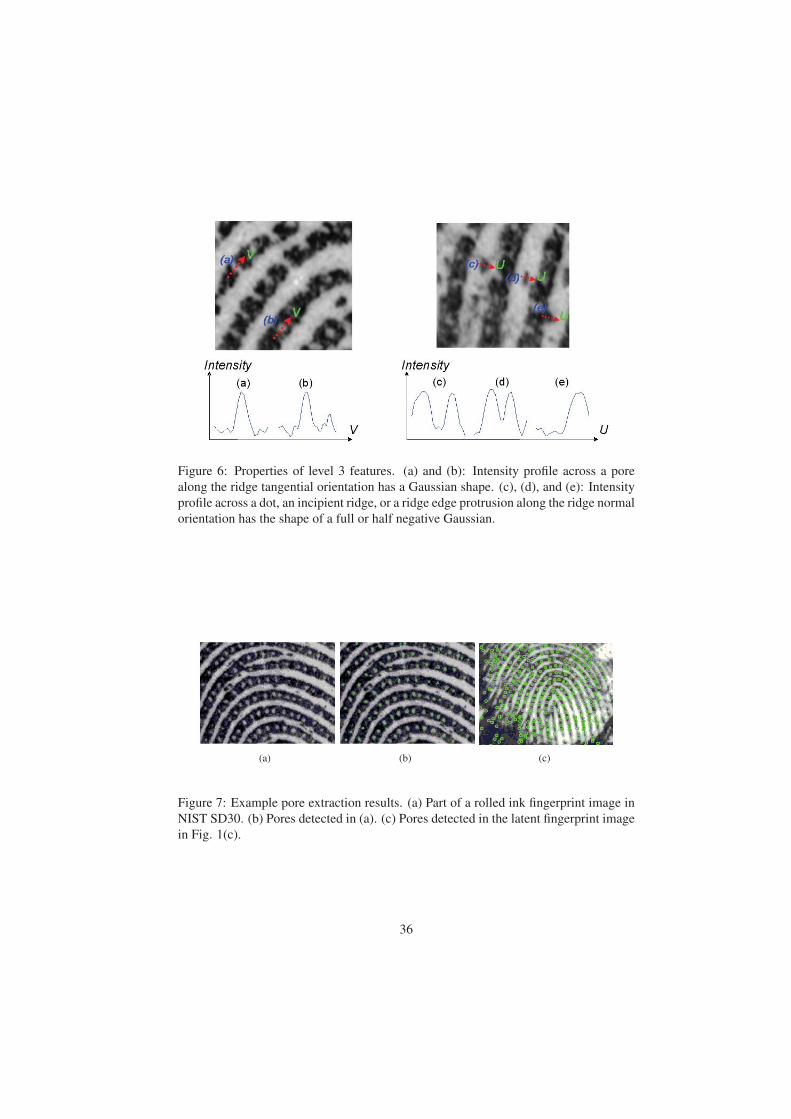
Figure 6: Properties of level 3 features. (a) and (b): Intensity profile across a pore
along the ridge tangential orientation has a Gaussian shape. (c), (d), and (e): Intensity
profile across a dot, an incipient ridge, or a ridge edge protrusion along the ridge normal
orientation has the shape of a full or half negative Gaussian.
(a) (b) (c)
Figure 7: Example pore extraction results. (a) Part of a rolled ink fingerprint image in
NIST SD30. (b) Pores detected in (a). (c) Pores detected in the latent fingerprint image
in Fig. 1(c).
36
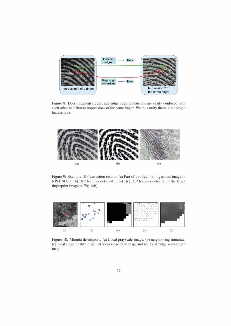
Figure 8: Dots, incipient ridges, and ridge edge protrusions are easily confused with
each other in different impressions of the same finger. We thus unify them into a single
feature type.
(a) (b) (c)
Figure 9: Example DIP extraction results. (a) Part of a rolled ink fingerprint image in
NIST SD30. (b) DIP features detected in (a). (c) DIP features detected in the latent
fingerprint image in Fig. 4(b).
(a) (b) (c) (d) (e)
Figure 10: Minutia descriptors. (a) Local grayscale image, (b) neighboring minutiae,
(c) local ridge quality map, (d) local ridge flow map, and (e) local ridge wavelength
map.
37
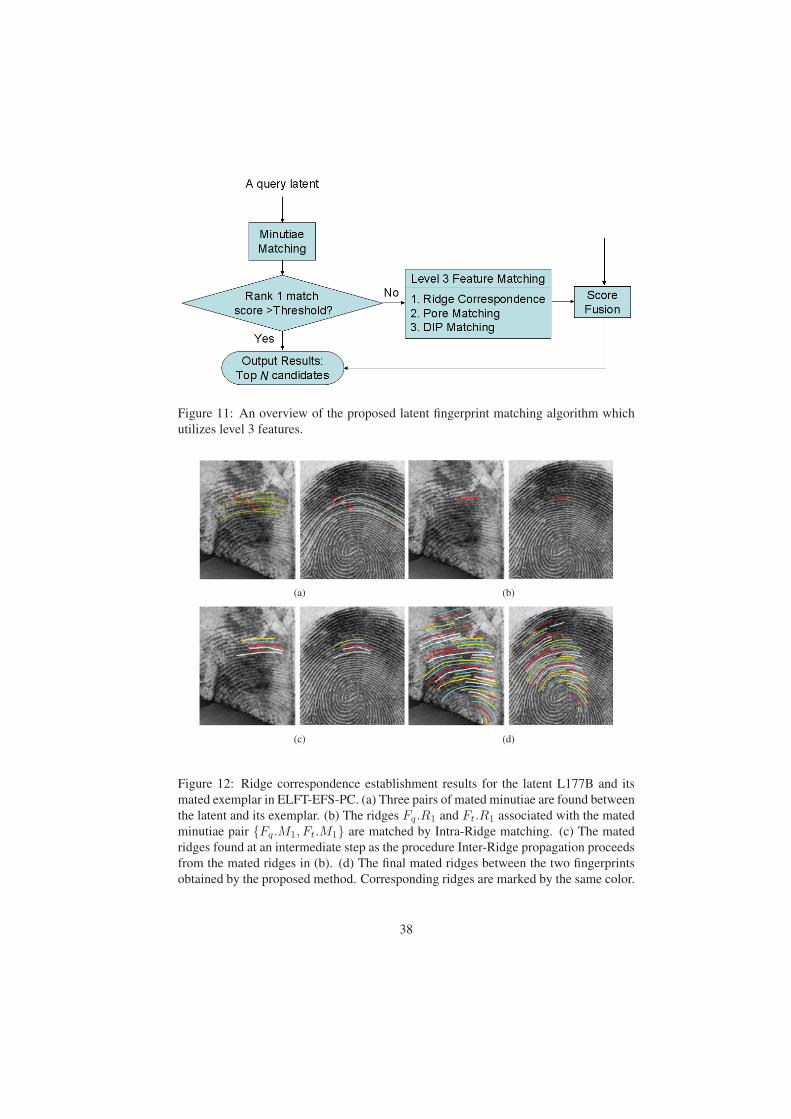
Figure 11: An overview of the proposed latent fingerprint matching algorithm which
utilizes level 3 features.
(a) (b)
(c) (d)
Figure 12: Ridge correspondence establishment results for the latent L177B and its
mated exemplar in ELFT-EFS-PC. (a) Three pairs of mated minutiae are found between
the latent and its exemplar. (b) The ridges Fq.R1 and Ft.R1 associated with the mated
minutiae pair {Fq.M1, Ft.M1} are matched by Intra-Ridge matching. (c) The mated
ridges found at an intermediate step as the procedure Inter-Ridge propagation proceeds
from the mated ridges in (b). (d) The final mated ridges between the two fingerprints
obtained by the proposed method. Corresponding ridges are marked by the same color.
38
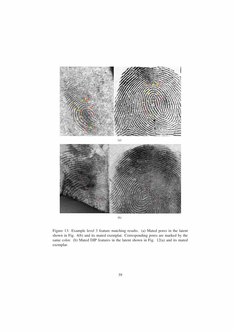
(a)
(b)
Figure 13: Example level 3 feature matching results. (a) Mated pores in the latent
shown in Fig. 4(b) and its mated exemplar. Corresponding pores are marked by the
same color. (b) Mated DIP features in the latent shown in Fig. 12(a) and its mated
exemplar.
39
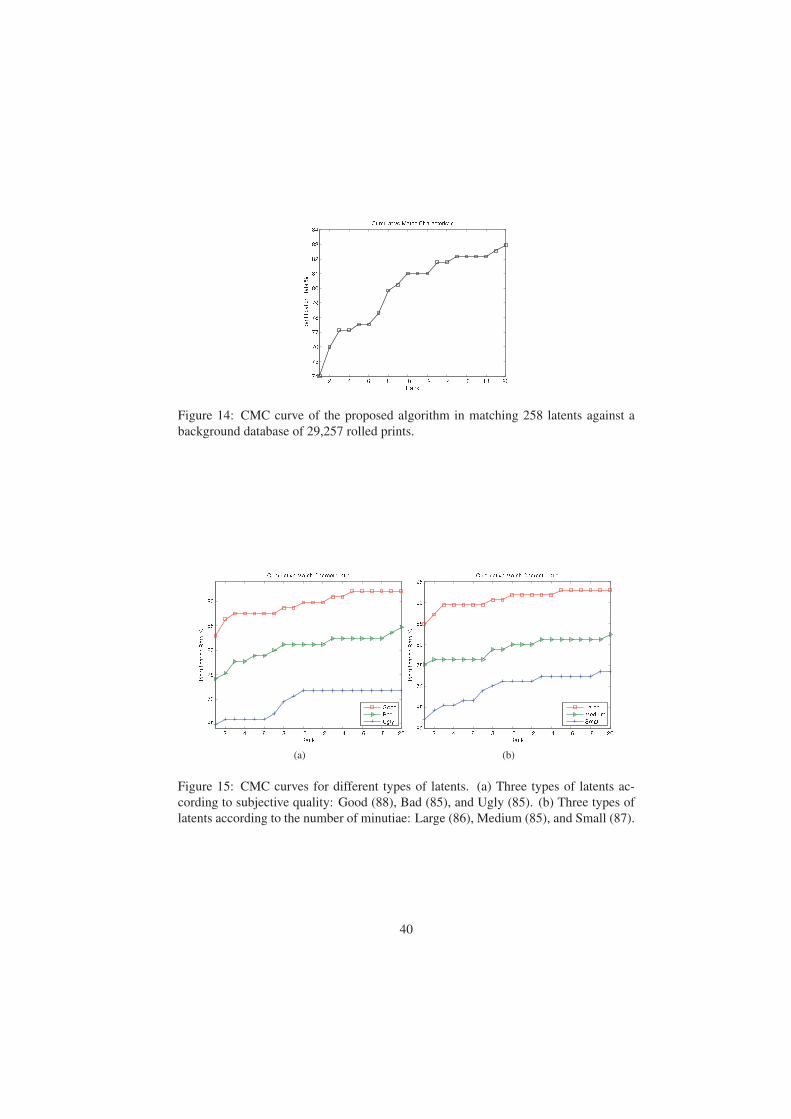
Figure 14: CMC curve of the proposed algorithm in matching 258 latents against a
background database of 29,257 rolled prints.
(a) (b)
Figure 15: CMC curves for different types of latents. (a) Three types of latents ac-
cording to subjective quality: Good (88), Bad (85), and Ugly (85). (b) Three types of
latents according to the number of minutiae: Large (86), Medium (85), and Small (87).
40
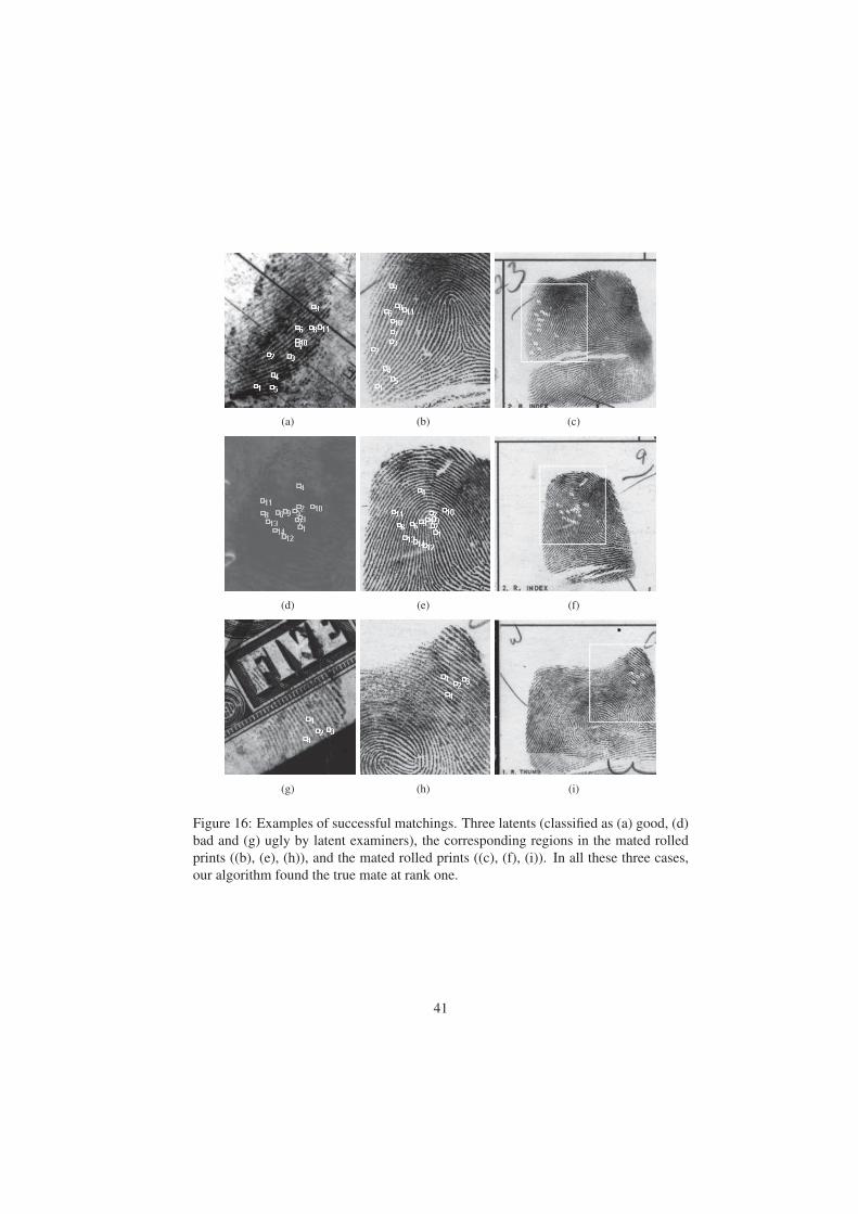
(a) (b) (c)
(d) (e) (f)
(g) (h) (i)
Figure 16: Examples of successful matchings. Three latents (classified as (a) good, (d)
bad and (g) ugly by latent examiners), the corresponding regions in the mated rolled
prints ((b), (e), (h)), and the mated rolled prints ((c), (f), (i)). In all these three cases,
our algorithm found the true mate at rank one.
41
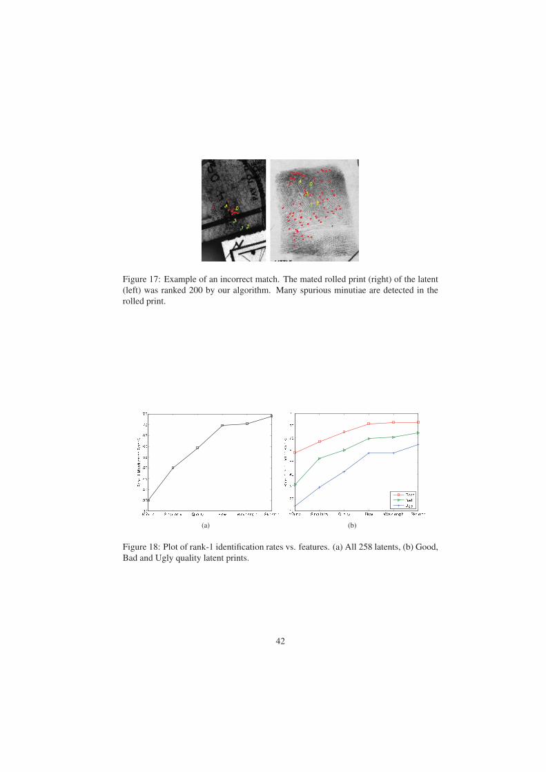
Figure 17: Example of an incorrect match. The mated rolled print (right) of the latent
(left) was ranked 200 by our algorithm. Many spurious minutiae are detected in the
rolled print.
(a) (b)
Figure 18: Plot of rank-1 identification rates vs. features. (a) All 258 latents, (b) Good,
Bad and Ugly quality latent prints.
42
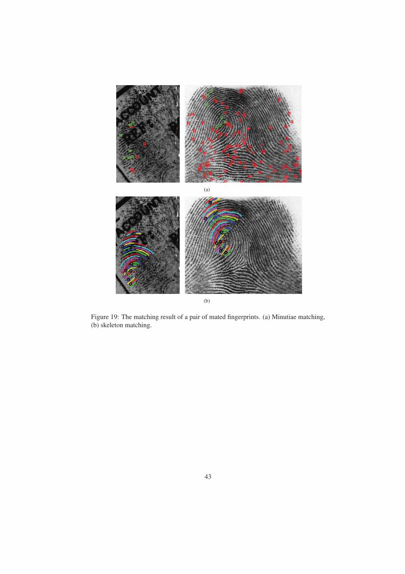
(a)
(b)
Figure 19: The matching result of a pair of mated fingerprints. (a) Minutiae matching,
(b) skeleton matching.
43
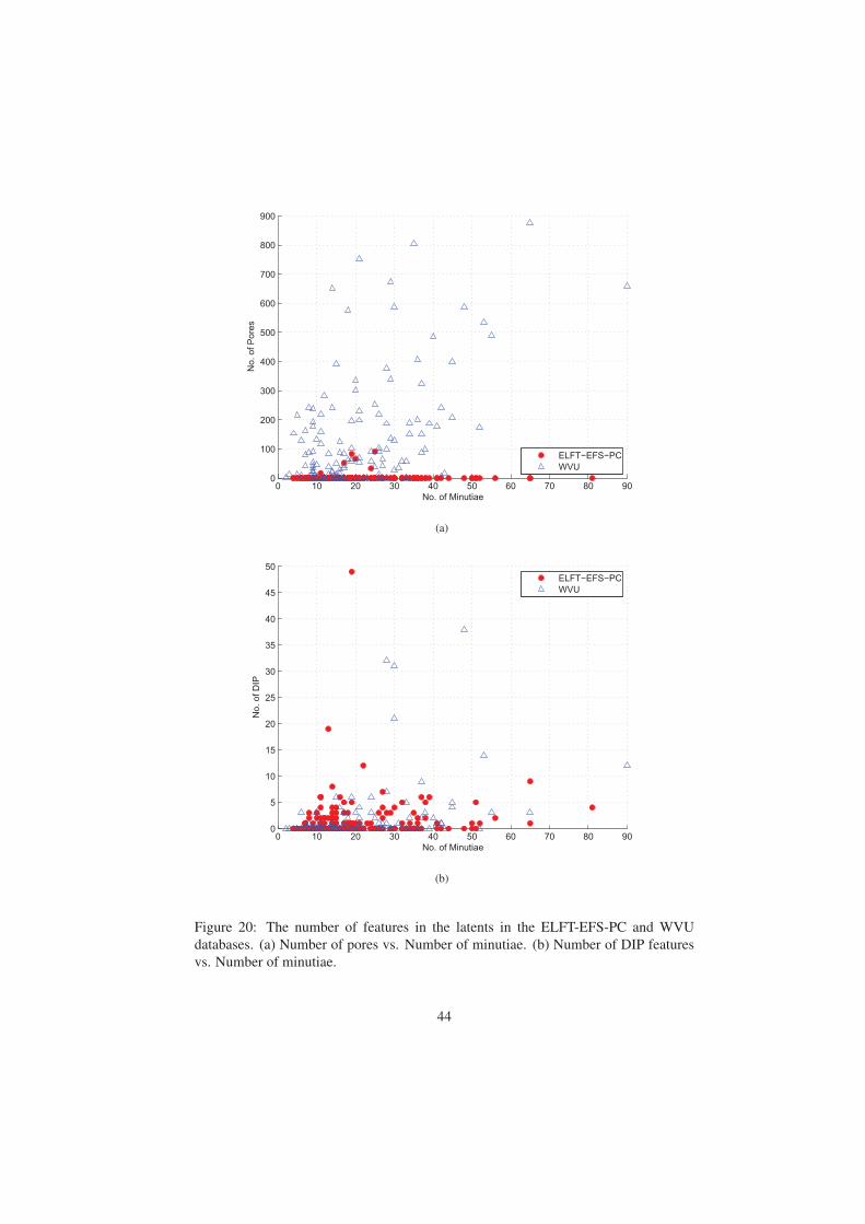
0 10 20 30 40 50 60 70 80 900
100
200
300
400
500
600
700
800
900
No. of Minutiae
No.
of P
ores
ELFT−EFS−PCWVU
(a)
0 10 20 30 40 50 60 70 80 900
5
10
15
20
25
30
35
40
45
50
No. of Minutiae
No.
of D
IP
ELFT−EFS−PCWVU
(b)
Figure 20: The number of features in the latents in the ELFT-EFS-PC and WVU
databases. (a) Number of pores vs. Number of minutiae. (b) Number of DIP features
vs. Number of minutiae.
44
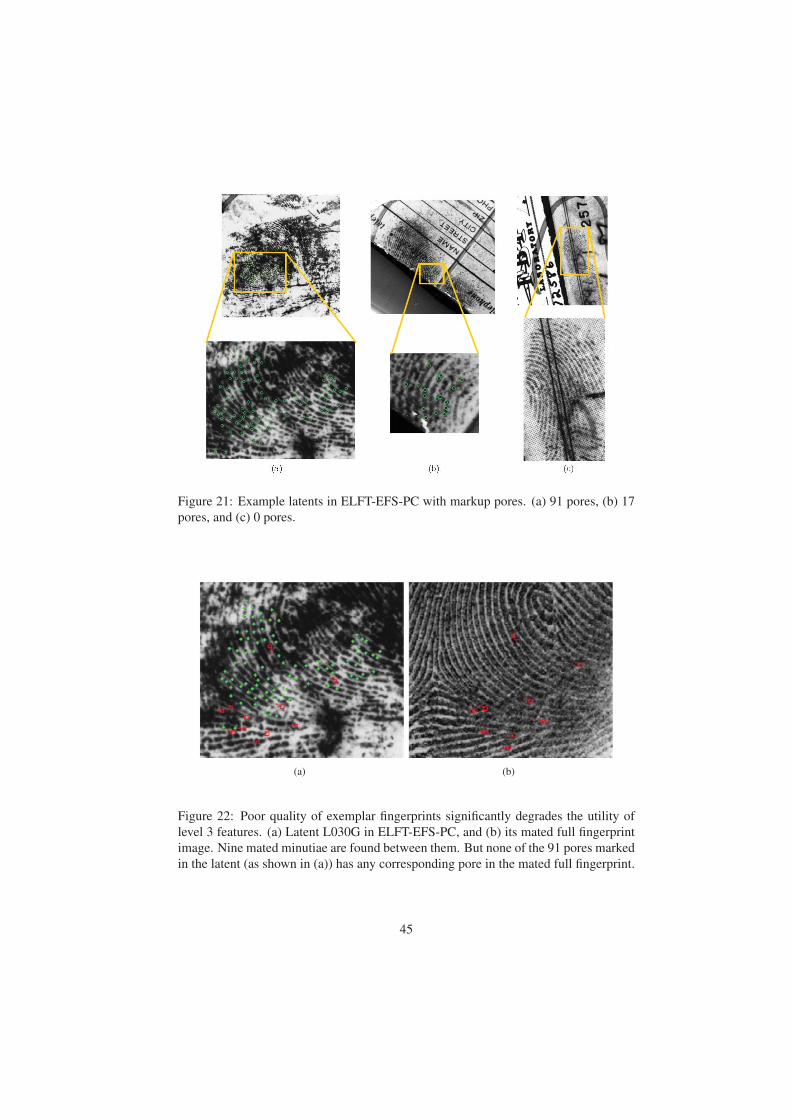
Figure 21: Example latents in ELFT-EFS-PC with markup pores. (a) 91 pores, (b) 17
pores, and (c) 0 pores.
(a) (b)
Figure 22: Poor quality of exemplar fingerprints significantly degrades the utility of
level 3 features. (a) Latent L030G in ELFT-EFS-PC, and (b) its mated full fingerprint
image. Nine mated minutiae are found between them. But none of the 91 pores marked
in the latent (as shown in (a)) has any corresponding pore in the mated full fingerprint.
45
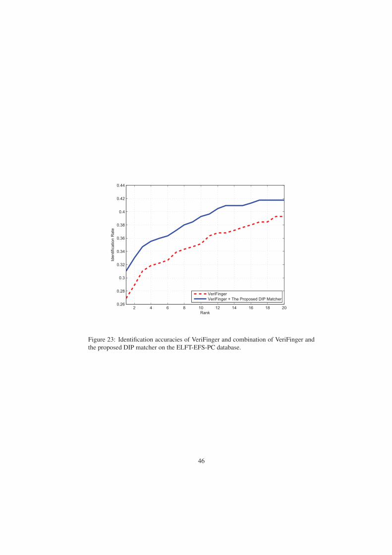
2 4 6 8 10 12 14 16 18 200.26
0.28
0.3
0.32
0.34
0.36
0.38
0.4
0.42
0.44
Rank
Iden
tific
atio
n R
ate
VeriFingerVeriFinger + The Proposed DIP Matcher
Figure 23: Identification accuracies of VeriFinger and combination of VeriFinger and
the proposed DIP matcher on the ELFT-EFS-PC database.
46
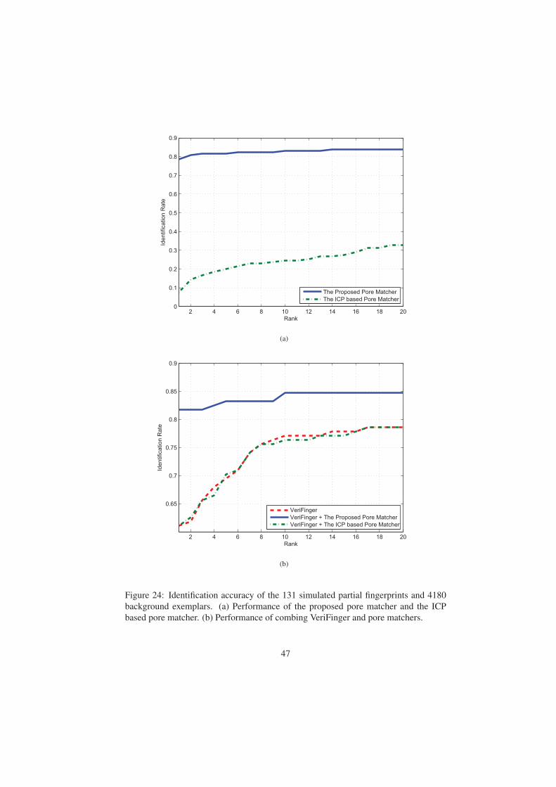
2 4 6 8 10 12 14 16 18 200
0.1
0.2
0.3
0.4
0.5
0.6
0.7
0.8
0.9
Rank
Iden
tific
atio
n R
ate
The Proposed Pore MatcherThe ICP based Pore Matcher
(a)
2 4 6 8 10 12 14 16 18 20
0.65
0.7
0.75
0.8
0.85
0.9
Rank
Iden
tific
atio
n R
ate
VeriFingerVeriFinger + The Proposed Pore MatcherVeriFinger + The ICP based Pore Matcher
(b)
Figure 24: Identification accuracy of the 131 simulated partial fingerprints and 4180
background exemplars. (a) Performance of the proposed pore matcher and the ICP
based pore matcher. (b) Performance of combing VeriFinger and pore matchers.
47
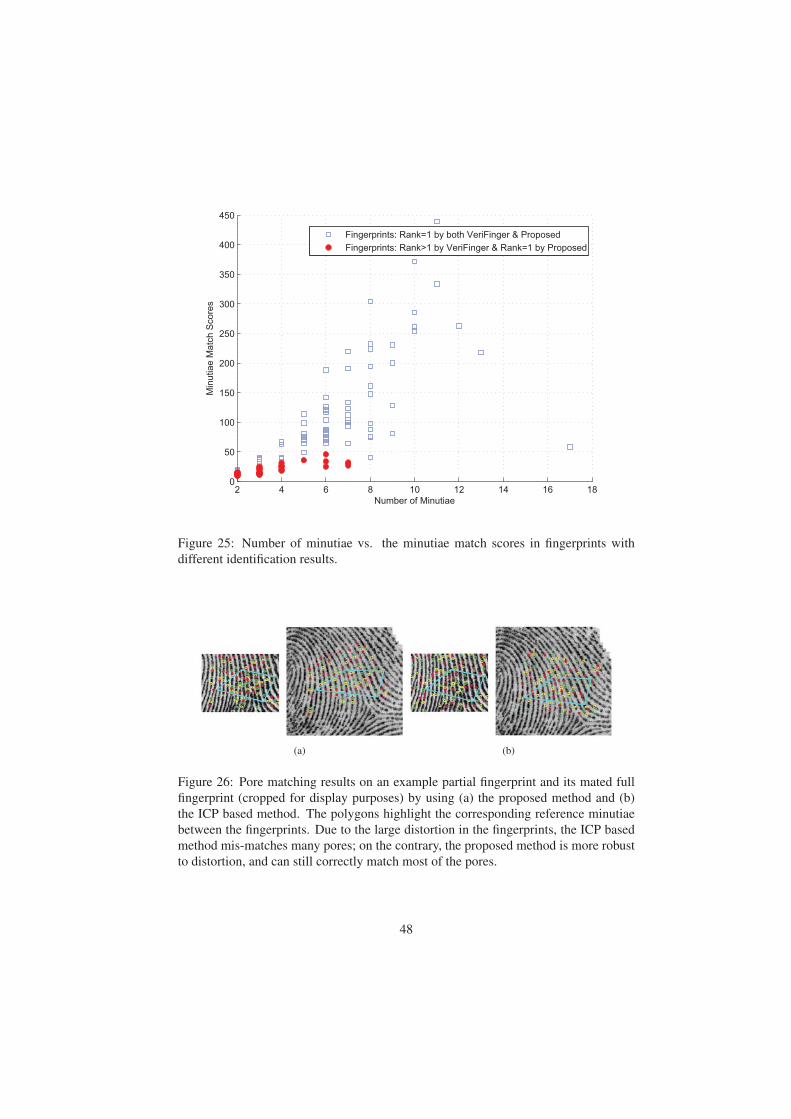
2 4 6 8 10 12 14 16 180
50
100
150
200
250
300
350
400
450
Number of Minutiae
Min
utia
e M
atch
Sco
res
Fingerprints: Rank=1 by both VeriFinger & ProposedFingerprints: Rank>1 by VeriFinger & Rank=1 by Proposed
Figure 25: Number of minutiae vs. the minutiae match scores in fingerprints with
different identification results.
(a) (b)
Figure 26: Pore matching results on an example partial fingerprint and its mated full
fingerprint (cropped for display purposes) by using (a) the proposed method and (b)
the ICP based method. The polygons highlight the corresponding reference minutiae
between the fingerprints. Due to the large distortion in the fingerprints, the ICP based
method mis-matches many pores; on the contrary, the proposed method is more robust
to distortion, and can still correctly match most of the pores.
48

4 Conclusions
4.1 Discussion of findingsExperimental results are summarized as follows:
1. Extended features at Level 1 lead to the largest matching accuracy improvement
than extended features at the other two levels. Among the Level 1 extended
features, ridge quality map and ridge flow map are the most important.
2. Extended features at Level 2, namely ridge skeleton, improve the rank-1 recog-
nition rate by 5%.
3. The “ugly” latents in NIST SD27 benefit the most from using extended features
at Level 1 and Level 2. The rank-1 recognition rate for “ugly” latents using
all extended features at Level 1 is already comparable to the rank-1 recogni-
tion rate for “good” latents using the current FBI standard features (minutiae +
core/delta).
4. The contribution of Level 3 features on ELFT-EFS-PC is minor. But, on a sim-
ulated partial fingerprint database, they do show obvious improvement in the
matching accuracy.
4.2 Implications for policy and practiceBased on the extensive experiments, we would like to offer the following recommen-
dations:
1. All extended features at Level 1 and Level 2 should be incorporated into AFIS as
soon as possible, since (i) these features are insensitive to image quality, (ii) do
not rely on high resolution images, and (iii) do lead to significant improvement
in the matching accuracy.
2. Algorithms and GUI tools should be developed to help fingerprint examiners
manually mark extended features (especially ridge skeleton) at Level 1 and Level
2 in latents, since it is a time-consuming task and general-purpose image editing
software (such as Photoshop) is not convenient for this task.
3. Utility of Level 3 features heavily rely on the image quality of both latents and
enrolled fingerprints. Since it is generally difficult or not possible to improve the
quality of latent prints, it is crucial to improve the quality of enrolled fingerprints
so that a sufficient number of Level 3 features can be extracted. This is necessary
for Level 3 features to play an important role in design and development of next
generation AFIS.
4.3 Implications for further researchThe proposed matching algorithm is still inferior to the performance of experienced la-
tent examiners, which may be caused by three major differences between the method-
ologies used by latent examiners and automatic matchers.
49

• Approaches used in matching ridge skeleton and minutiae (or Level 2 features)
are different. Latent examiners employ a “ridges in sequence” method [50] in the
matching process, which is robust to noise and distortion. While the proposed
skeleton matching algorithm tries to mimic such a method, it is not robust in
the presence of large amounts of noise and distortion. The minutiae matching
algorithm is also prone to spurious minutiae and distortion.
• The approach used to match the detailed ridge features (or Level 3 features) is
different. When latent examiners compare the detailed ridge features in finger-
prints, there is no explicit separation between feature extraction and matching
stages. The separation of feature extraction and matching in automatic systems
leads to some information loss. In addition, the automatic feature extractor may
not be able to extract Level 3 features from rolled prints that are always compat-
ible with the features marked by latent examiners.
• The approach to utilizing negative evidence is different. Latent examiners can
determine a pair of fingerprints as unmatched based on a single unmatched minu-
tia which is located in the good quality region of the two fingerprints. This is a
risky proposition for fingerprint algorithms.
We plan to improve the latent matching accuracy by reducing these differences.
Our study shows that extended features at Level 3 lead to much smaller contribu-
tion to matching accuracy compared to extend features at Level 1 and Level 2. Since
the image quality of enrolled fingerprints in the databases used in this study is not
sufficiently good for extracting Level 3 features, the experiments on Level 3 features
should be repeated when other fingerprint databases with better image quality become
available. The experiments reported here utilized a 500 ppi database and a 1000 ppi
database, but not a database of mixed resolution images. As pointed out by a reviewer
of this report, “the real world state of AFIS databases will be of mixed resolution.”
This calls for additional experiments involving extended features on mixed resolution
databases.
Manual feature markings for poor quality latent fingerprints is a time consuming
and tedious task. Considering that latent examiners often have to process many latents
within a limited time period, significant attention should be paid to the automatic la-
tent feature extraction problem. Given the performance gap between automatic and
semi-automatic latent matching systems, human intervention is likely to be necessary
for some time. One way to reduce manual processing is to define a latent fingerprint
quality measure, which is continuously updated when latent examiners are marking
features. Once the quality measure reaches a predefined threshold, the latent exam-
iners are notified that the image quality is already good enough to perform a latent
search.
50
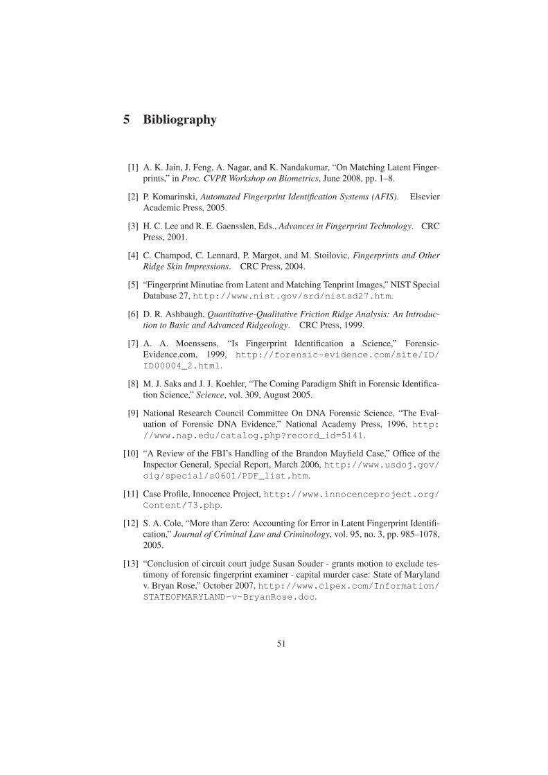
5 Bibliography
[1] A. K. Jain, J. Feng, A. Nagar, and K. Nandakumar, “On Matching Latent Finger-
prints,” in Proc. CVPR Workshop on Biometrics, June 2008, pp. 1–8.
[2] P. Komarinski, Automated Fingerprint Identification Systems (AFIS). Elsevier
Academic Press, 2005.
[3] H. C. Lee and R. E. Gaensslen, Eds., Advances in Fingerprint Technology. CRC
Press, 2001.
[4] C. Champod, C. Lennard, P. Margot, and M. Stoilovic, Fingerprints and OtherRidge Skin Impressions. CRC Press, 2004.
[5] “Fingerprint Minutiae from Latent and Matching Tenprint Images,” NIST Special
Database 27, http://www.nist.gov/srd/nistsd27.htm.
[6] D. R. Ashbaugh, Quantitative-Qualitative Friction Ridge Analysis: An Introduc-tion to Basic and Advanced Ridgeology. CRC Press, 1999.
[7] A. A. Moenssens, “Is Fingerprint Identification a Science,” Forensic-
Evidence.com, 1999, http://forensic-evidence.com/site/ID/ID00004_2.html.
[8] M. J. Saks and J. J. Koehler, “The Coming Paradigm Shift in Forensic Identifica-
tion Science,” Science, vol. 309, August 2005.
[9] National Research Council Committee On DNA Forensic Science, “The Eval-
uation of Forensic DNA Evidence,” National Academy Press, 1996, http://www.nap.edu/catalog.php?record_id=5141.
[10] “A Review of the FBI’s Handling of the Brandon Mayfield Case,” Office of the
Inspector General, Special Report, March 2006, http://www.usdoj.gov/oig/special/s0601/PDF_list.htm.
[11] Case Profile, Innocence Project, http://www.innocenceproject.org/Content/73.php.
[12] S. A. Cole, “More than Zero: Accounting for Error in Latent Fingerprint Identifi-
cation,” Journal of Criminal Law and Criminology, vol. 95, no. 3, pp. 985–1078,
2005.
[13] “Conclusion of circuit court judge Susan Souder - grants motion to exclude tes-
timony of forensic fingerprint examiner - capital murder case: State of Maryland
v. Bryan Rose,” October 2007, http://www.clpex.com/Information/STATEOFMARYLAND-v-BryanRose.doc.
51
[14] V. N. Dvornychenko and M. D. Garris, “Summary of NIST Latent Fingerprint
Testing Workshop,” NISTIR 7377, November 2006, http://fingerprint.nist.gov/latent/ir_7377.pdf.
[15] C. Wilson, “Fingerprint Vendor Technology Evaluation 2003: Summary of Re-
sults and Analysis Report,” NISTIR 7123, June 2004, http://fpvte.nist.gov/report/ir_7123_analysis.pdf.
[16] “Evaluation of Latent Fingerprint Technologies 2007,” http://fingerprint.nist.gov/latent/elft07/.
[17] NIST, “Summary of Results from ELFT07 Phase I Testing,” September
2007, http://fingerprint.nist.gov/latent/elft07/phase1_aggregate.pdf.
[18] M. Indovina, V. Dvornychenko, E. Tabassi, G. Quinn, P. Grother, S. Meagher, and
M. Garris, “ELFT Phase II - An Evaluation of Automated Latent Fingerprint Iden-
tification Technologies,” NISTIR 7577, April 2009, http://fingerprint.nist.gov/latent/NISTIR_7577_ELFT_PhaseII.pdf.
[19] CDEFFS: The ANIS/NIST Committee to Define an Extended Fingerprint
Feature Set, http://fingerprint.nist.gov/standard/cdeffs/index.html.
[20] “American National Standard for Information Technology - Finger Minutiae
Format for Data Interchange,” ANSI/INCITS 378-2004, 2004, http://www.incits.org.
[21] “NIST 8-Bit Gray Scale Images of Fingerprint Image Groups (FIGS),” NIST Spe-
cial Database 4, http://www.nist.gov/srd/nistsd4.htm.
[22] “NIST Mated Fingerprint Card Pairs 2 (MFCP2),” NIST Special Database 14,
http://www.nist.gov/srd/nistsd14.htm.
[23] The NAS Committee on Identifying the Needs of the Forensic Science Commu-
nity, “Strengthening Forensic Science in the United States: A Path Forward,”
National Academy Press, 2009, http://www.nap.edu/catalog.php?record_id=12589.
[24] P. Lo and B. Bavarian, “Expert Matcher Fingerprint System,” US Patent No.
5,960,101, 1999.
[25] M. Hara and H. Toyama, “Method and Apparatus for Matching Streaked Pattern
Image,” US Patent No. 7,295,688, 2007.
[26] NIST Minutiae Interoperability Exchange Test (MINEX), http://fingerprint.nist.gov/minex04/.
[27] NIST Proprietary Fingerprint Template (PFT) Testing, http://fingerprint.nist.gov/pft/.
52
[28] R. M. McCabe and M. D. Garris, “Summary of April 2005 ANSI/NIST
Fingerprint Standard Update Workshop,” NISTIR 7242, July 2005,
http://fingerprint.nist.gov/standard/archived_workshops/workshop1/ir7242.pdf.
[29] SWGFAST, Scientific Working Group on Friction Ridge Analysis, Study and
Technology, http://www.swgfast.org.
[30] CDEFFS, Data Format for the Interchange of Extended Fingerprint and
Palmprint Features, WORKING DRAFT Version 0.2, January 2008,
http://fingerprint.nist.gov/standard/cdeffs/Docs/CDEFFS_DraftStd_v02_2008-01-18.pdf.
[31] J. Feng, “Combining Minutiae Descriptors for Fingerprint Matching,” PatternRecognition, vol. 41, no. 1, pp. 342–352, 2008.
[32] M. Tico and P. Kuosmanen, “Fingerprint Matching Using an Orientation-based
Minutia Descriptor,” IEEE Trans. Pattern Analysis and Machine Intelligence,
vol. 25, no. 8, pp. 1009–1014, 2003.
[33] J. Gu, J. Zhou, and C. Yang, “Fingerprint Recognition by Combining Global
Structure and Local Cues,” IEEE Trans. Image Processing, vol. 15, no. 7, pp.
1952–1964, 2006.
[34] P. Lo and G. Yu, “Print Matching Method and System Using Direction Images,”
US Patent Application Publication No. 2008/0273769A1, 2008.
[35] A. K. Jain, Y. Chen, and M. Demirkus, “Pores and Ridges: High-Resolution
Fingerprint Matching Using Level 3 Features,” IEEE Trans. Pattern Analysis andMachine Intelligence, vol. 29, no. 1, pp. 15–27, 2007.
[36] D. Wan and J. Zhou, “Fingerprint Recognition Using Model-based Density Map,”
IEEE Trans. Image Processing, vol. 15, no. 6, pp. 1690–1696, 2006.
[37] J. Feng, Z. Ouyang, and A. Cai, “Fingerprint Matching Using Ridges,” PatternRecognition, vol. 39, no. 11, pp. 2131 – 2140, 2006.
[38] A. K. Jain, L. Hong, and R. M. Bolle, “On-line Fingerprint Verification,” IEEETrans. Pattern Analysis and Machine Intelligence, vol. 19, no. 4, pp. 302–314,
1997.
[39] J. Zhou, F. Chen, N. Wu, and C. Wu, “Crease Detection from Fingerprint Images
and Its Applications in Elderly People,” Pattern Recognition, vol. 42, no. 5, pp.
896–906, 2009.
[40] J. D. Stosz and L. A. Alyea, “Automated System for Fingerprint Authentication
Using Pores and Ridge Structure,” in Proc. SPIE Conf. Automatic Systems for theIdentification and Inspection of Humans, vol. 2277, no. 1, 1994, pp. 210–223.
[41] International Biometric Group (IBG), “Analysis of Level 3 Features at High Res-
olutions: Phase II - Final Report,” Tech. Rep., 2008.
53
[42] Y. Chen and A. K. Jain, “Dots and Incipients: Extended Features for Partial Fin-
gerprint Matching,” in Proc. Biometrics Symposium, September 2007, pp. 1–6.
[43] A. Anthonioz, N. Egli, C. Champod, C. Neumann, R. Puch-Solls, and
A. Bromage-Griffiths, “Level 3 Details and Their Role in Fingerprint Identifica-
tion: A Survey among Practitioners,” Journal of Forensic Identification, vol. 58,
no. 5, pp. 562–589, 2008.
[44] Neurotechnology Inc., VeriFinger, http://www.neurotechnology.com.
[45] D. Maltoni, D. Maio, A. K. Jain, and S. Prabhakar, Handbook of FingerprintRecognition (2nd Edition). Springer, 2009.
[46] Z. Kovacs Vajna, “A Fingerprint Verification System Based on Triangular Match-
ing and Dynamic Time Warping,” IEEE Trans. Pattern Analysis and MachineIntelligence, vol. 22, no. 11, pp. 1266–1276, 2000.
[47] X. Chen, J. Tian, and X. Yang, “A New Algorithm for Distorted Fingerprints
Matching Based on Normalized Fuzzy Similarity Measure,” IEEE Trans. ImageProcessing, vol. 15, no. 3, pp. 767–776, 2006.
[48] A. M. Bazen and S. H. Gerez, “Elastic Minutiae Matching by Means of Thin-
Plate Spline Models,” in Proc. 16th Int’l Conf. Pattern Recognition, 2002, pp.
985–988.
[49] T.-Y. Jea and V. Govindaraju, “A Minutia-Based Partial Fingerprint Recognition
System,” Pattern Recognition, vol. 38, no. 10, pp. 1672 – 1684, 2005.
[50] SWGFAST, Memo to Mike McCabe (NIST) Regarding ANSI/NIST ITL 1-
2000, November 2005, http://fingerprint.nist.gov/standard/cdeffs/Docs/SWGFAST_Memo.pdf.
[51] J. Feng, S. Yoon, and A. K. Jain, “Latent Fingerprint Matching: Fusion of Rolled
and Plain Fingerprints,” in Proc. 2nd International Conference on Biometrics(ICB), June 2009, pp. 695–704.
[52] E. Tabassi, C. Wilson, and C. Watson, “Fingerprint Image Quality,” NISTIR 7151,
August 2004, http://fingerprint.nist.gov/NFIS/ir_7151.pdf.
[53] Q. Zhao, D. Zhang, L. Zhang, and N. Luo, “Adaptive fingerprint pore modeling
and extraction,” Pattern Recognition, vol. 43, no. 8, pp. 2833-2844, 2010.
[54] Q. Zhao, L. Zhang, D. Zhang, and N. Luo, “Direct pore matching for fingerprint
recognition,” Proc. of ICB, Italy, pp. 597-606, 2009.
[55] M. Indovina and A. Hicklin, ELFT-EFS NIST Evaluation of Latent FingerprintTechnologies: Extended Feature Sets, Evaluation #1, Preliminary Report, Jan.
2010, http://fingerprint.nist.gov/latent/ELFT-EFS/.
[56] A. K. Jain and J. Feng, “Latent fingerprint matching,” IEEE Trans. Pattern Anal-ysis and Machine Intelligence, vol. 33, no. 1, pp. 88-100, 2011.
54
[57] Q. Zhao and A. K. Jain, “On the utility of extended fingerprint features: A study
on pores,” Proc. of IEEE Workshop on Biometrics, CVPR, June 2010.
[58] T. Lindeberg, “Feature detection with automatic scale selection,” InternationalJournal of Computer Vision, vol. 30, no. 2, pp. 79-116, 1998.
[59] H. Fronthaler, K. Kollreider, J. Bigun, J. Fierrez, F. Alonso-Fernandez, J. Ortega-
Garcia, and J. Gonzalez-Rodriguez,“Fingerprint image-quality estimation and its
application to multialgorithm verification,” IEEE Trans. IFS, vol. 3, no. 2, pp.
331-338, 2008.
[60] A. Ross, K. Nandakumar, and A. K. Jain, Handbook of Multibiometrics. Springer,
2006.
55
6 Dissemination
6.1 Publications6.1.1 Journal Papers
1. A. K. Jain and J. Feng, “Latent Fingerprint Matching,” IEEE Transactions on
Pattern Analysis and Machine Intelligence, vol. 33, no. 1, pp. 88-100, 2011.
2. J. Feng and A. K. Jain, “Fingerprint Reconstruction: From Minutiae to Phase,”
IEEE Transactions on Pattern Analysis and Machine Intelligence, vol. 33, no. 2,
pp. 209-223, 2011.
6.1.2 Conference Papers
1. Q. Zhao and A. K. Jain, “On the Utility of Extended Fingerprint Features: A
Study on Pores,” IEEE Computer Society Workshop on Biometrics, pp. 9-16,
San Francisco, June 2010.
2. J. Bohn and V. Despigel, “Fingerprint skeleton matching based on local descrip-
tor,” IEEE 3rd International Conference on Biometrics: Theory, Applications,
and Systems (BTAS), pp. 1-6, Washington, Sept. 2009.
3. J. Feng, S. Yoon, and A. K. Jain, “Latent Fingerprint Matching: Fusion of Rolled
and Plain Fingerprints,” Proc. International Conference on Biometrics (ICB),
Italy, June 2009.
4. J. Feng, and A. K. Jain, “FM Model Based Fingerprint Reconstruction from
Minutiae Template,” Proc. International Conference on Biometrics (ICB), pp.
544-553, Italy, June 2009.
5. Y. Chen and A. K. Jain, “Beyond Minutiae: A Fingerprint Individuality Model
with Pattern, Ridge and Pore Features,” Proc. International Conference on Bio-
metrics (ICB), pp. 523-533, Italy, June 2009.
6. J. Feng, and A. K. Jain “Filtering Large Fingerprint Database for Latent Match-
ing,” Proc. International Conference on Pattern Recognition (ICPR), pp. 1-4,
Tampa, Dec. 2008.
7. A. K. Jain, J. Feng, A. Nagar and K. Nandakumar, “On Matching Latent Finger-
prints,” IEEE Computer Society Workshop on Biometrics, pp. 1-8, Alaska, June
2008.
6.1.3 Technical Reports
1. Q. Zhao, J. Feng and A. K. Jain, “Latent Fingerprint Matching: Utility of Level 3
Features,” MSU Technical Report, MSU-CSE-10-14, August, 2010 (Submitted
to the IEEE Transactions on Information Forensics and Security).
56

6.2 Presentations6.2.1 Conference Presentations
This research has been presented at the following conferences:
1. IEEE Computer Society Workshop on Biometrics, San Francisco, California,
June 2010.
2. International Conference on Biometrics: Theory, Applications, and Systems
(BTAS), Washington D.C., September 2009.
3. International Conference on Biometrics (ICB), Italy, June 2009.
4. International Conference on Pattern Recognition (ICPR), Tampa, Florida, De-
cember 2008.
5. IEEE Computer Society Workshop on Biometrics, Anchorage, Alaska, June
2008.
6.2.2 Invited Talks
This research has also been presented in invited talks at the following institutions:
1. Chosun University, Dec 2009;
2. Yonsei Unversity, Nov 2009;
3. University of Maryland, Oct 2009;
4. Korea University, Oct 2009;
5. Pusan National University, Oct 2009;
6. Tsinghua University, June 2009;
7. University of North Texas, April 2009;
8. University of Florida, Oct 2008;
9. Chulalongkorn University, Nov 2008;
10. TCS, Hyderabad, India, Nov 2008;
11. Istanbul Technical University, Sept. 2008;
12. Cogent, Aug. 2008.
57

AppendixThe research conducted by MorphoTrak team under this NIJ project is described in the
following paper attached here.
J. Bohn and V. Despigel, “Fingerprint skeleton matching based on local descriptor,”
IEEE 3rd International Conference on Biometrics: Theory, Applications, and Systems
(BTAS), pp. 1-6, Washington, Sept. 2009.
58
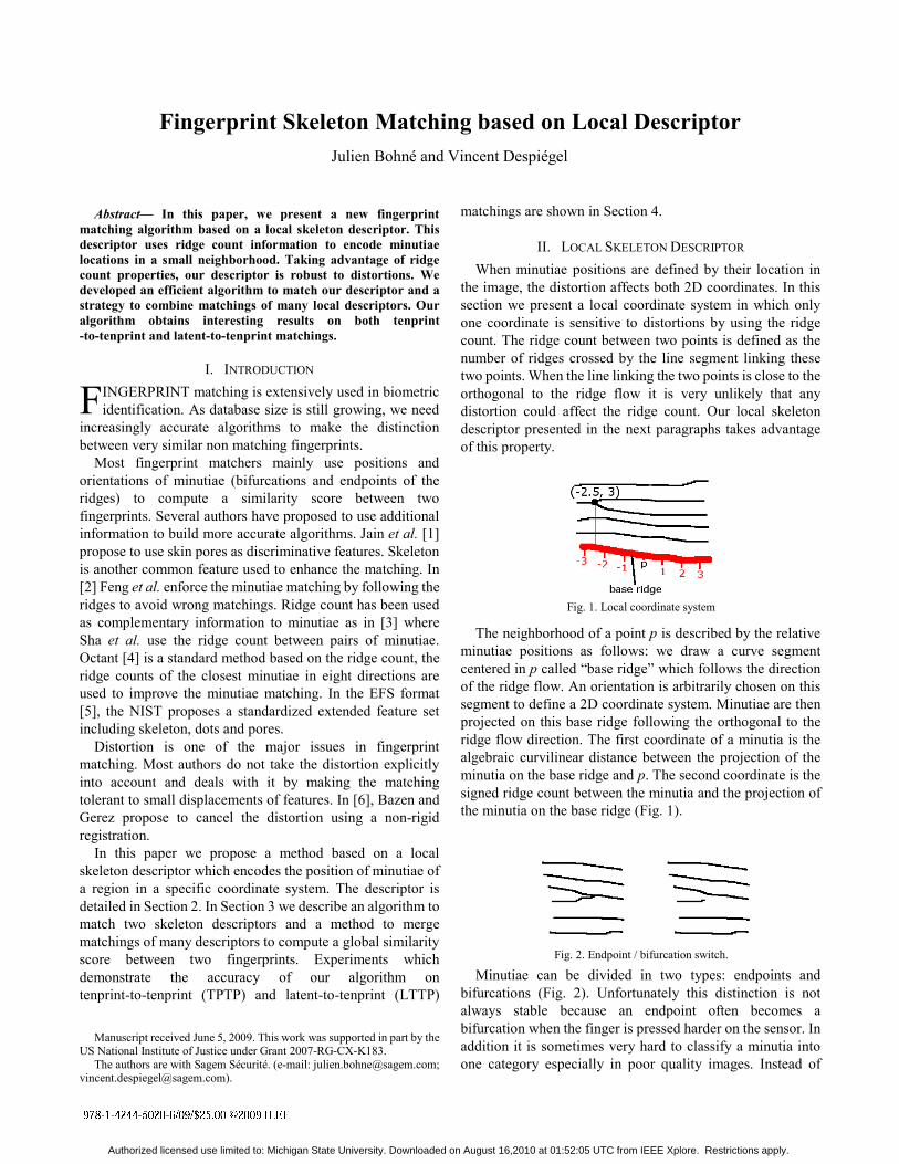
Abstract— In this paper, we present a new fingerprint matching algorithm based on a local skeleton descriptor. This descriptor uses ridge count information to encode minutiae locations in a small neighborhood. Taking advantage of ridge count properties, our descriptor is robust to distortions. We developed an efficient algorithm to match our descriptor and a strategy to combine matchings of many local descriptors. Our algorithm obtains interesting results on both tenprint -to-tenprint and latent-to-tenprint matchings.
I. INTRODUCTION INGERPRINT matching is extensively used in biometric identification. As database size is still growing, we need
increasingly accurate algorithms to make the distinction between very similar non matching fingerprints.
Most fingerprint matchers mainly use positions and orientations of minutiae (bifurcations and endpoints of the ridges) to compute a similarity score between two fingerprints. Several authors have proposed to use additional information to build more accurate algorithms. Jain et al. [1] propose to use skin pores as discriminative features. Skeleton is another common feature used to enhance the matching. In [2] Feng et al. enforce the minutiae matching by following the ridges to avoid wrong matchings. Ridge count has been used as complementary information to minutiae as in [3] where Sha et al. use the ridge count between pairs of minutiae. Octant [4] is a standard method based on the ridge count, the ridge counts of the closest minutiae in eight directions are used to improve the minutiae matching. In the EFS format [5], the NIST proposes a standardized extended feature set including skeleton, dots and pores.
Distortion is one of the major issues in fingerprint matching. Most authors do not take the distortion explicitly into account and deals with it by making the matching tolerant to small displacements of features. In [6], Bazen and Gerez propose to cancel the distortion using a non-rigid registration.
In this paper we propose a method based on a local skeleton descriptor which encodes the position of minutiae of a region in a specific coordinate system. The descriptor is detailed in Section 2. In Section 3 we describe an algorithm to match two skeleton descriptors and a method to merge matchings of many descriptors to compute a global similarity score between two fingerprints. Experiments which demonstrate the accuracy of our algorithm on tenprint-to-tenprint (TPTP) and latent-to-tenprint (LTTP)
Manuscript received June 5, 2009. This work was supported in part by the
US National Institute of Justice under Grant 2007-RG-CX-K183. The authors are with Sagem Sécurité. (e-mail: [email protected];
matchings are shown in Section 4.
II. LOCAL SKELETON DESCRIPTOR When minutiae positions are defined by their location in
the image, the distortion affects both 2D coordinates. In this section we present a local coordinate system in which only one coordinate is sensitive to distortions by using the ridge count. The ridge count between two points is defined as the number of ridges crossed by the line segment linking these two points. When the line linking the two points is close to the orthogonal to the ridge flow it is very unlikely that any distortion could affect the ridge count. Our local skeleton descriptor presented in the next paragraphs takes advantage of this property.
The neighborhood of a point p is described by the relative minutiae positions as follows: we draw a curve segment centered in p called “base ridge” which follows the direction of the ridge flow. An orientation is arbitrarily chosen on this segment to define a 2D coordinate system. Minutiae are then projected on this base ridge following the orthogonal to the ridge flow direction. The first coordinate of a minutia is the algebraic curvilinear distance between the projection of the minutia on the base ridge and p. The second coordinate is the signed ridge count between the minutia and the projection of the minutia on the base ridge (Fig. 1).
Minutiae can be divided in two types: endpoints and bifurcations (Fig. 2). Unfortunately this distinction is not always stable because an endpoint often becomes a bifurcation when the finger is pressed harder on the sensor. In addition it is sometimes very hard to classify a minutia into one category especially in poor quality images. Instead of
Fingerprint Skeleton Matching based on Local Descriptor Julien Bohné and Vincent Despiégel
F
Fig. 1. Local coordinate system
Fig. 2. Endpoint / bifurcation switch.
Authorized licensed use limited to: Michigan State University. Downloaded on August 16,2010 at 01:52:05 UTC from IEEE Xplore. Restrictions apply.
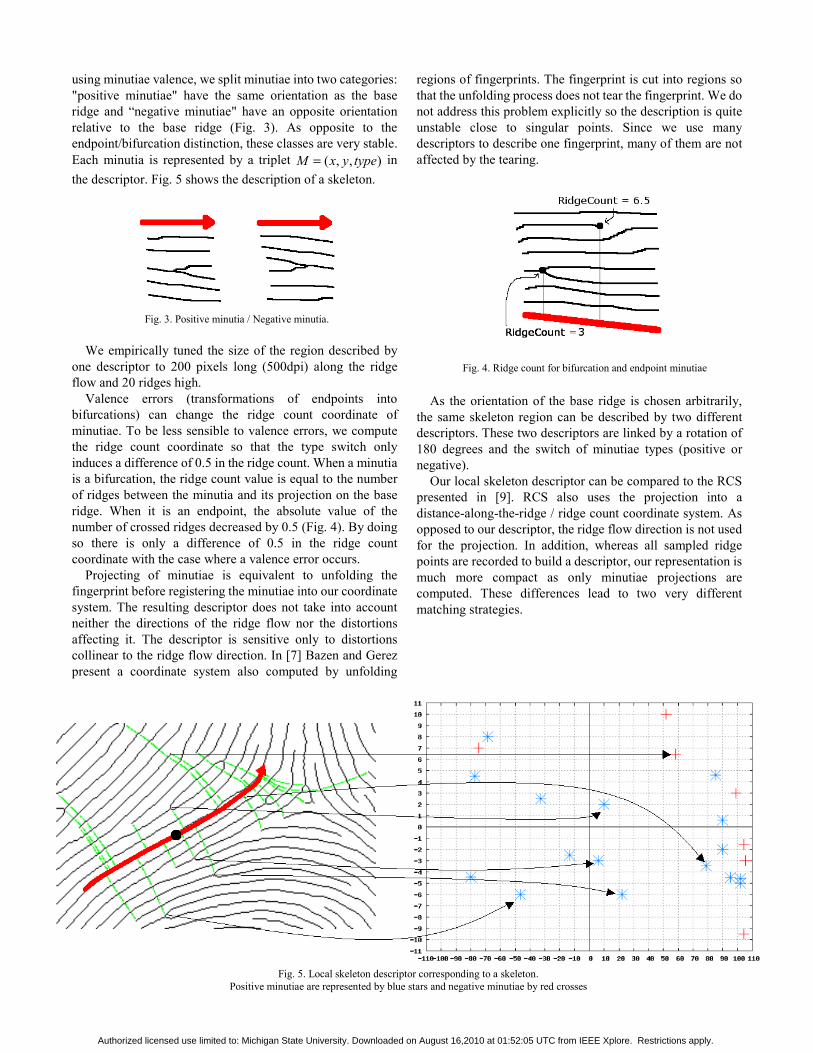
using minutiae valence, we split minutiae into two categories: "positive minutiae" have the same orientation as the base ridge and “negative minutiae" have an opposite orientation relative to the base ridge (Fig. 3). As opposite to the endpoint/bifurcation distinction, these classes are very stable. Each minutia is represented by a triplet ),,( typeyxM = in the descriptor. Fig. 5 shows the description of a skeleton.
We empirically tuned the size of the region described by one descriptor to 200 pixels long (500dpi) along the ridge flow and 20 ridges high.
Valence errors (transformations of endpoints into bifurcations) can change the ridge count coordinate of minutiae. To be less sensible to valence errors, we compute the ridge count coordinate so that the type switch only induces a difference of 0.5 in the ridge count. When a minutia is a bifurcation, the ridge count value is equal to the number of ridges between the minutia and its projection on the base ridge. When it is an endpoint, the absolute value of the number of crossed ridges decreased by 0.5 (Fig. 4). By doing so there is only a difference of 0.5 in the ridge count coordinate with the case where a valence error occurs.
Projecting of minutiae is equivalent to unfolding the fingerprint before registering the minutiae into our coordinate system. The resulting descriptor does not take into account neither the directions of the ridge flow nor the distortions affecting it. The descriptor is sensitive only to distortions collinear to the ridge flow direction. In [7] Bazen and Gerez present a coordinate system also computed by unfolding
regions of fingerprints. The fingerprint is cut into regions so that the unfolding process does not tear the fingerprint. We do not address this problem explicitly so the description is quite unstable close to singular points. Since we use many descriptors to describe one fingerprint, many of them are not affected by the tearing.
As the orientation of the base ridge is chosen arbitrarily, the same skeleton region can be described by two different descriptors. These two descriptors are linked by a rotation of 180 degrees and the switch of minutiae types (positive or negative).
Our local skeleton descriptor can be compared to the RCS presented in [9]. RCS also uses the projection into a distance-along-the-ridge / ridge count coordinate system. As opposed to our descriptor, the ridge flow direction is not used for the projection. In addition, whereas all sampled ridge points are recorded to build a descriptor, our representation is much more compact as only minutiae projections are computed. These differences lead to two very different matching strategies.
Fig. 5. Local skeleton descriptor corresponding to a skeleton.
Positive minutiae are represented by blue stars and negative minutiae by red crosses
Fig. 4. Ridge count for bifurcation and endpoint minutiae
Fig. 3. Positive minutia / Negative minutia.
Authorized licensed use limited to: Michigan State University. Downloaded on August 16,2010 at 01:52:05 UTC from IEEE Xplore. Restrictions apply.

III. FINGERPRINT MATCHING ALGORITHM USING LOCAL SKELETON DESCRITORS
A. Outline Our matching algorithm can be summarized as follows:
1. Fingerprints are registered based on matched minutiae using our standard minutiae matcher;
2. N pairs of corresponding points are selected in the two fingerprints and a descriptor is computed for each point;
3. Corresponding descriptors are matched: they are first aligned then the similarity between the two descriptors is computed;
4. The average of the N scores is outputted.
B. Matching of two local skeleton descriptors The descriptor presented in the previous section is sensitive to some perturbations. The matching algorithm is designed to address the following issues:
1. The distortion along the ridge flow direction; 2. A small relative displacement of the origins of the
descriptors; 3. The arbitrary choice of the orientation of base
ridges; 4. The appearance / disappearance of minutiae between
the search print and the reference print; 5. The noise in the location of the minutiae in the
direction of the ridge flow. The location of a minutia can shift up to fifteen pixels at 500dpi when an endpoint becomes a bifurcation.
The matching algorithm is composed of two stages. The first stage performs the alignment of the two descriptors and addresses issues of translations, distortions and the arbitrary choice of the base ridges orientations. Once the two descriptors are registered, the second stage finds pairs of minutiae between the search print and the reference print using dynamic programming. These pairs are used to compute a similarity score between the two descriptors. 1) Registering stage
The objective of this stage is to register the descriptor from the reference fingerprint on the descriptor from the search fingerprint to best superpose matching minutiae. As our local descriptor is around 200 pixels long along the ridge flow direction, we consider that the distortion along the ridge flow direction can be approximated by a simple linear stretch. The transformation is defined by s the linear stretch along the ridge flow, tx the translation along the ridge flow and ty the translation orthogonal to the ridge flow. The main issue in estimation of the best transformation is that matching minutiae pairs are unknown. We therefore think in a probabilistic way and seek for the transformation which best superposes the biggest minutiae set.
To find the optimal parameters (s,tx,ty) we use a generalized Hough transform. Each couple of pairs of potentially matched minutiae votes for each (s,tx,ty) in the discretized parameter space proportionally to the probability that (s,tx,ty) superposes the two pairs of minutiae. We
consider that two minutiae can potentially match if they are of same type (positive or negative). As the multiplication is the natural operator in the scale space, the algorithm works in log scale. Votes are accumulated in the parameter space considering every couple of pairs of potentially matched minutiae:
( )( )∑
==∈
∈
=
lRef
kSrc
jRef
iSrc
lRef
jRef
kSrc
iSrc
typetypetypetypeMMMM
lRef
kSrc
jRef
iSrc MMMMtytxsP
tytxsVote
and with print reference from minutiae,
printsearch from minutiae,
,,,,),log(
,),log(
To be robust to the arbitrary choice for the base ridge orientation, two parameter spaces are used: one for each possible orientation of the reference base ridge. To register the two descriptors, we choose the (s,tx,ty) which receives the most votes in the parameter space.
As the two variables TX and TY are independent we have: ( )
( ) ( )lRef
kSrc
jRef
iSrc
lRef
kSrc
jRef
iSrc
lRef
kSrc
jRef
iSrc
yyyytyTYPxxxxtxTXsSP
MMMMtyTYtxTXsSP
,,,,,,,
,,,,,
=×===
===
In the remaining part of this section we describe how to compute these expressions.
Let us first focus on the two first parameters: s and tx. From 2 pairs of matched minutiae ( ) , j
RefiSrc MM and
( ) , lRef
kSrc MM the parameters s and tx superposing the abscissa
of the 2 pairs can be computed,
⎪⎩
⎪⎨
⎧
×−=−−=
⇒⎪⎩
⎪⎨⎧
−×=−×=
jRef
iSrc
lRef
jRef
kSrc
iSrc
lRef
kSrc
jRef
iSrc
xsxtxxxxxs
txxsxtxxsx
The matcher needs to be robust to noise in the minutiae locations. To take explicitly this noise into account we want to compute the probability distribution function
( )lRef
kSrc
jRef
iSrc xxxxtxsP ,,,, considering a gaussian noise with a
known standard deviation. Unfortunately this distribution cannot be accurately approximated by a 2D gaussian centered on the best (s,tx) with a fixed covariance matrix because the distances k
SrciSrc xx − and l
Refj
Ref xx − act as levers on the
computation of s (Fig. 6). However it is possible to compute the exact value of ( )l
RefkSrc
jRef
iSrc xxxxtxTXsSP ,,,, == . Using the
Bayes theorem, ( )lRef
kSrc
jRef
iSrc xxxxtxTXsSP ,,,, == can be split:
( )( ) ( )l
RefkSrc
jRef
iSrc
lRef
kSrc
jRef
iSrc
lRef
kSrc
jRef
iSrc
xxxxsSPxxxxstxTXP
xxxxtxTXsSP
,,,,,,,
,,,,
==
===
Let iSrcX be a gaussian random variable of law ( )i
SrciSrcx σ,N
and jRefX be a gaussian random variable of law ( )j
Refj
Refx σ,N ,
let kSrc
iSrcSrc XXD −= ,
SrcD is a gaussian random variable of law
⎟⎠⎞
⎜⎝⎛ +=−= 22, k
SrciSrcD
kSrc
iSrcD SrcSrc
xx σσσμN and RefD is a
gaussian random variable of law____________________
⎟⎠⎞
⎜⎝⎛ +=−= 22, l
Refj
RefDlRef
jRefD RefRef
xx σσσμN . The scale variable
RefSrc DDS = is a ratio of two gaussian random variables. The
distribution of this type of variable has a well known
Authorized licensed use limited to: Michigan State University. Downloaded on August 16,2010 at 01:52:05 UTC from IEEE Xplore. Restrictions apply.
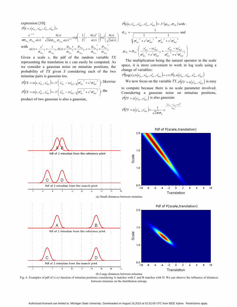
expression [10]: ( )
⎟⎟⎠
⎞⎜⎜⎝
⎛⎟⎟⎠
⎞⎜⎜⎝
⎛⎟⎟⎠
⎞⎜⎜⎝
⎛−−+
==−
)(2)(
)()(
21exp
)(2)(
)(
,,,2
2/3
2/
sasberf
sasbc
sasb
sae
xxxxsSP
RefSrcRefSrc DDDD
c
lRef
kSrc
jRef
iSrc
σσπσπσ
with 2
2
2
2
2222
2
,)(,1)(Ref
Ref
Src
Src
Ref
Ref
Src
Src
RefSrc D
d
D
d
D
d
D
d
DD
cs
sbssaσμ
σμ
σμ
σμ
σσ+=+=+=
Given a scale s, the pdf of the random variable TX representing the translation in x can easily be computed. As we consider a gaussian noise on minutiae positions, the probability of TX given S considering each of the two minutiae pairs is gaussian too.
( ) ⎟⎠⎞
⎜⎝⎛ +−==
222,,, j
RefiSrc
jRef
iSrc
jRef
iSrc ssxxxxstxTXP σσN , likewise
( ) ⎟⎠⎞
⎜⎝⎛ +−==
222,,, l
RefkSrc
lRef
kSrc
lRef
kSrc ssxxxxstxTXP σσN , the
product of two gaussian is also a gaussian,
( ) ( )
⎟⎟
⎠
⎞
⎜⎜
⎝
⎛
+
−+
+
−=
++
+
=
=
2222222
222222
and11
1
: with,,,,,
lRef
kSrc
lRef
kSrc
jRef
iSrc
jRef
iSrc
TXTX
lRef
kSrc
jRef
iSrc
TX
TXTXlRef
kSrc
jRef
iSrc
s
sxx
s
sxx
ss
xxxxstxP
σσσσσμ
σσσσ
σ
σμN
The multiplication being the natural operator in the scale space, it is more convenient to work in log scale using a change of variables:
( ) ( )lRef
kSrc
jRef
iSrc
lRef
kSrc
jRef
iSrc xxxxtxsPsxxxxtxsP ,,,,,,,),log( ×=
We now focus on the variable TY, ( )jRef
iSrc yytyTYP ,= is easy
to compute because there is no scale parameter involved. Considering a gaussian noise on minutiae positions,
( )jRef
iSrc yytyTYP ,= is also gaussian:
( )( )
2
2
2
21, ty
jRef
iSrc tyyy
ty
jRef
iSrc eyytyTYP σ
σπ
+−−
==
(a) Small distances between minutiae
(b) Large distances between minutiae
Fig. 6. Examples of pdf of (s,tx) function of minutiae positions considering A matches with C and B matches with D. We can observe the influence of distances between minutiae on the distribution entropy
Authorized licensed use limited to: Michigan State University. Downloaded on August 16,2010 at 01:52:05 UTC from IEEE Xplore. Restrictions apply.

2) Minutiae matching and score computation When the descriptors are registered, the probability that
two minutiae match is function of their type (positive or negative) and of the distance between them:
( )( )( ) ( )
⎪⎩
⎪⎨
⎧=∝
−−
−−
otherwise 0 if,
2
2
2
2
22 jRef
iSrc
xxyy
jRef
iSrc typetypeeMMmatchP x
jRef
iSrc
y
jRef
iSrc
σσ
σx needs to be much bigger than σy because the ridge count is more stable than the location along the ridge flow direction. The matching needs to be less tolerant in areas of high minutiae density to avoid matching any of these areas with any other high density area. Therefore σx and σy are functions of the local minutiae density.
Finding the best matches is a bipartite graph matching problem. From a cost matrix ( )( )j
RefiSrcij MMmatchPcost ,1−=
we search for the set A of matches minimizing the sum of matching costs with the constraint that no minutia is used more than once. The value of the minimum can be used to compute a similarity score.
⎟⎟⎠
⎞⎜⎜⎝
⎛−= ∑
∈AjiijA
costScore),(
min
under constraints AkiAji ∈¬∃⇒∈ ),(),( with k ≠ j. The Kuhn-Munkres algorithm [9] also called Hungarian
algorithm solves this problem with polynomial complexity using dynamic programming. With the previously presented cost matrix, the score always increases when adding matches, even if those matches are highly improbable. This is not the sought behaviour because it automatically boosts the score when there are many minutiae.
The tuning of the tradeoff between the influence of true and wrong matches can be achieved by subtracting a constant α∈[0,1] to each value of the cost matrix. If α is close to 0, good matches increase the score but wrong ones do not have any effect. If α is close to 1, wrong matches decrease the score but good ones do not have any effect. In our implementation, we set α=0.6 to balance the influence of good and wrong matches.
Some minutiae cannot be matched between the search and the reference. Instead of matching minutiae at any cost we would rather consider some minutiae as outliers. It can be done by simply adding lines and columns for outliers in the cost matrix:
( )( ) }} minutiaesearch #
minutiae reference#
minutiae reference #minutiaesearch #
02/)(
2/)(,1
⎟⎟⎠
⎞−⎜⎜⎝
⎛
−−−
=α
αα penalty
penaltyMMmatchP
costj
RefiSrc
with penalty-α the threshold below which two minutiae are not matched. Minutiae matched with lines and columns of penalties are considered as outliers.
We use the score computed by the Hungarian algorithm fed by this matrix as similarity score between two descriptors.
C. Similarity score of two fingerprints To compute a global similarity score between two
fingerprints, we merge scores obtained from many local
descriptors. We first compute matched minutiae pairs with our standard
minutiae matcher and use these matches to register the two fingerprints using a thin plate spline. This strategy is close to that of Bazen and Gerez in [6] but unlike them we do not use an iterative scheme. Descriptors with the same location on the two registered fingerprints are then compared. The global similarity score is the mean of the similarity scores of all descriptors pairs.
We want to describe locations which are more likely to give discriminative descriptors. The selection of the descriptors used to compute the global similarity score is based on the minutiae density on the search fingerprint. Areas with very high minutiae density are not discriminative because they often contain many false minutiae. Areas with very low minutiae density are not discriminative because of the lack of information.
We also want selected descriptors to be scattered over the fingerprint. The number of extracted descriptors usually varies from 3 to 10. A greedy selection which balances these two objectives is done as follows:
1. A descriptor is computed for every point of a regular grid to make a candidate list;
2. A potential is computed for each descriptor function of the local minutiae density in the descriptor;
3. The descriptor d with the highest potential is selected and removed from the candidate list;
4. If the potential p(d) is below a threshold or there are more than N descriptors selected, exit;
5. The potential of every descriptor d’ is updated with
the rule: ( ) ( )( )
⎟⎟
⎠
⎞
⎜⎜
⎝
⎛−×=
−+ 2
2
2',
1 1'' σdddst
kk edpdp
with dst(d,d’) being the Euclidian distance between d and d’ locations;
6. Go to step 3.
IV. EXPERIMENTS
A. Tenprint-to-tenprint matching We evaluate our local skeleton descriptor matching
algorithm on a proprietary database composed of 30 000 rolled fingerprints on which skeletons are automatically extracted by our proprietary coder. We run 15 000 genuine tests and 900 000 impostor tests. We compare our skeleton algorithm with our standard minutiae matcher. We can see in Fig. 7 that the skeleton algorithm makes around twice as many false acceptance as the minutiae matcher. This difference of accuracy can be explained by the fact that the skeleton algorithm does not use orientation information and that it only performs many local matchings and does not use global coherence as the minutiae matcher does. In addition, the skeleton algorithm uses correspondences from the minutiae matcher to register the two fingerprints, therefore when the minutiae matcher fails completely the skeleton algorithm fails too. However the information used by the skeleton algorithm is complementary of the minutiae, so the
Authorized licensed use limited to: Michigan State University. Downloaded on August 16,2010 at 01:52:05 UTC from IEEE Xplore. Restrictions apply.
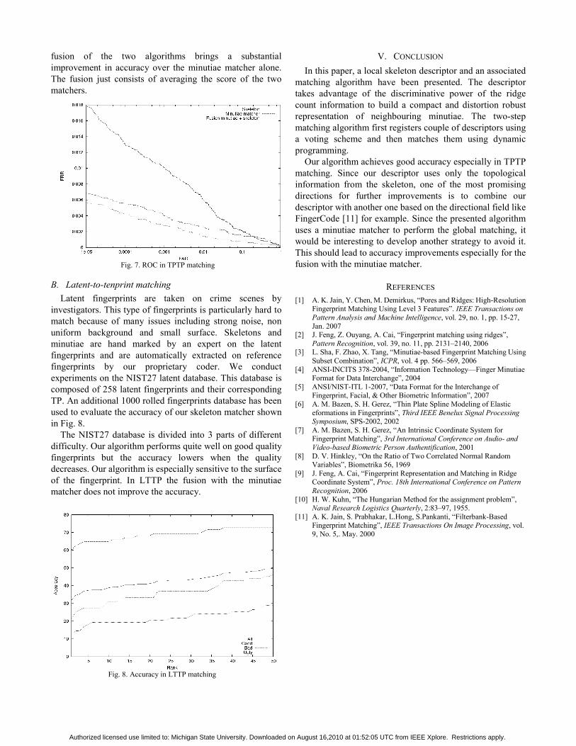
fusion of the two algorithms brings a substantial improvement in accuracy over the minutiae matcher alone. The fusion just consists of averaging the score of the two matchers.
B. Latent-to-tenprint matching Latent fingerprints are taken on crime scenes by
investigators. This type of fingerprints is particularly hard to match because of many issues including strong noise, non uniform background and small surface. Skeletons and minutiae are hand marked by an expert on the latent fingerprints and are automatically extracted on reference fingerprints by our proprietary coder. We conduct experiments on the NIST27 latent database. This database is composed of 258 latent fingerprints and their corresponding TP. An additional 1000 rolled fingerprints database has been used to evaluate the accuracy of our skeleton matcher shown in Fig. 8.
The NIST27 database is divided into 3 parts of different difficulty. Our algorithm performs quite well on good quality fingerprints but the accuracy lowers when the quality decreases. Our algorithm is especially sensitive to the surface of the fingerprint. In LTTP the fusion with the minutiae matcher does not improve the accuracy.
V. CONCLUSION In this paper, a local skeleton descriptor and an associated
matching algorithm have been presented. The descriptor takes advantage of the discriminative power of the ridge count information to build a compact and distortion robust representation of neighbouring minutiae. The two-step matching algorithm first registers couple of descriptors using a voting scheme and then matches them using dynamic programming.
Our algorithm achieves good accuracy especially in TPTP matching. Since our descriptor uses only the topological information from the skeleton, one of the most promising directions for further improvements is to combine our descriptor with another one based on the directional field like FingerCode [11] for example. Since the presented algorithm uses a minutiae matcher to perform the global matching, it would be interesting to develop another strategy to avoid it. This should lead to accuracy improvements especially for the fusion with the minutiae matcher.
REFERENCES [1] A. K. Jain, Y. Chen, M. Demirkus, “Pores and Ridges: High-Resolution
Fingerprint Matching Using Level 3 Features”. IEEE Transactions on Pattern Analysis and Machine Intelligence, vol. 29, no. 1, pp. 15-27, Jan. 2007
[2] J. Feng, Z. Ouyang, A. Cai, “Fingerprint matching using ridges”, Pattern Recognition, vol. 39, no. 11, pp. 2131–2140, 2006
[3] L. Sha, F. Zhao, X. Tang, “Minutiae-based Fingerprint Matching Using Subset Combination”, ICPR, vol. 4 pp. 566–569, 2006
[4] ANSI-INCITS 378-2004, “Information Technology—Finger Minutiae Format for Data Interchange”, 2004
[5] ANSI/NIST-ITL 1-2007, “Data Format for the Interchange of Fingerprint, Facial, & Other Biometric Information”, 2007
[6] A. M. Bazen, S. H. Gerez, “Thin Plate Spline Modeling of Elastic eformations in Fingerprints”, Third IEEE Benelux Signal Processing Symposium, SPS-2002, 2002
[7] A. M. Bazen, S. H. Gerez, “An Intrinsic Coordinate System for Fingerprint Matching”, 3rd International Conference on Audio- and Video-based Biometric Person Authentification, 2001
[8] D. V. Hinkley, “On the Ratio of Two Correlated Normal Random Variables”, Biometrika 56, 1969
[9] J. Feng, A. Cai, “Fingerprint Representation and Matching in Ridge Coordinate System”, Proc. 18th International Conference on Pattern Recognition, 2006
[10] H. W. Kuhn, “The Hungarian Method for the assignment problem”, Naval Research Logistics Quarterly, 2:83–97, 1955.
[11] A. K. Jain, S. Prabhakar, L.Hong, S.Pankanti, “Filterbank-Based Fingerprint Matching”, IEEE Transactions On Image Processing, vol. 9, No. 5,. May. 2000
Fig. 7. ROC in TPTP matching
Fig. 8. Accuracy in LTTP matching
Authorized licensed use limited to: Michigan State University. Downloaded on August 16,2010 at 01:52:05 UTC from IEEE Xplore. Restrictions apply.