Embed Size (px)
Citation preview

Automatic fluxer


1
Thank you for having chosen the X-300 fusion machine from Katanax. To enjoy years of reliable, efficient and safe use of this time-saving instrument, please read this manual thoroughly and keep it in a safe and handy place for future reference.
Should you have any question regarding the use, maintenance or repair of your instrument, kindly contact Katanax directly for assistance (see page 84 for contact details).
© September 2021, Katanax inc. All rights reserved.
2
Index Index ............................................................................................... 2
Installation ...................................................................................... 5 Box contents ............................................................................................ 5 Location ................................................................................................... 5 Leveling ................................................................................................... 7 Connection ............................................................................................... 7 Mold size .................................................................................................. 7 Crucible holder setup ................................................................................ 7 Questions ? .............................................................................................. 7
Introduction .................................................................................... 8 Fusion basics ............................................................................................ 8 Automatic fluxers ..................................................................................... 8 The X-300 fluxer ...................................................................................... 8 Main features of the Katanax X-300 ........................................................ 11
Precautions ................................................................................... 13
How the unit works ...................................................................... 14 Heating .................................................................................................. 14 Multiple configurations ............................................................................ 14 Access to the furnace ............................................................................. 14 Agitation and pouring of the melt ............................................................ 15 Cooling .................................................................................................. 15 Solution agitation ................................................................................... 15
Using the X-300 (basic) ............................................................... 16 Operation of the safety shield.................................................................. 16 The main running screen ........................................................................ 17 Loading a program ................................................................................. 20 During a fusion ....................................................................................... 21 The right ingredients .............................................................................. 22 Care of the platinumware ....................................................................... 25 Crucible installation ................................................................................ 26 Mold installation ..................................................................................... 27 A general fusion ..................................................................................... 28 Making solutions ..................................................................................... 29 Description of the fusion steps ................................................................ 30
Programming the X-300 (advanced) ........................................... 32 Viewing the fusion parameters ................................................................ 32 Unlocking the advanced mode ................................................................ 36 Managing fusion methods ....................................................................... 37 Preparing a fusion program ..................................................................... 38 Heating steps ......................................................................................... 38 Pouring step ........................................................................................... 39 Cooling steps ......................................................................................... 40

3
On-the-fly editing ................................................................................... 41
Global parameters ........................................................................ 43 Language ............................................................................................... 43 Holding temperature offset ..................................................................... 43 Startup tolerance.................................................................................... 44 End beep ............................................................................................... 44 Automatic shut-off delay ......................................................................... 44 Safety shield protection .......................................................................... 45 Fusion counter ....................................................................................... 45
Special parameters ....................................................................... 46 Accessing the Special parameters ........................................................... 46 Offsets ................................................................................................... 46 Loop operation ....................................................................................... 47 Movement testing ................................................................................... 47
Fusion troubleshooting................................................................. 48 Disk cracks............................................................................................. 48 Disk crystallizes ...................................................................................... 48 Incomplete disk ...................................................................................... 48 Non-homogenous disk ............................................................................ 49 Bubbles in disk ....................................................................................... 49
Periodic inspection ....................................................................... 50 Warning ................................................................................................. 50 Inspection schedule table ........................................................................ 50 Flux spillage on holders ........................................................................... 50 Holders alignment and functionality ......................................................... 51 Air filter for the molds cooling ................................................................. 52 Furnace chimney cleaning ....................................................................... 52 Element terminal connections ................................................................. 53 Furnace cleanliness ................................................................................ 53 Thermocouple junction ........................................................................... 54 Swing motion system ............................................................................ 54
Service operations ........................................................................ 56 Warning ................................................................................................. 56 Crucible holder removal .......................................................................... 56 Crucible holder installation ...................................................................... 57 Mold holder removal ............................................................................... 57 Mold holder configuration, assembly and alignment ................................. 58 Heating element replacement ................................................................. 60 Top/back panel removal ......................................................................... 62 Side panel removal ................................................................................. 63 Bottom panels removal ........................................................................... 64
Appendix A – Technical specifications ......................................... 66 Electrical ................................................................................................ 66 Physical ................................................................................................. 66
Appendix B – Warranty ................................................................ 67
Appendix C – Firmware and program transfers .......................... 68 Preset programs ..................................................................................... 68

4
Backup or restore by USB ....................................................................... 69
Appendix D – CPLive : Data logging ............................................ 71 Introduction to data logging .................................................................... 71 Installing EasyConverter ......................................................................... 71 Enable data logging ................................................................................ 72 Sample tracking ..................................................................................... 73 Copying logs to a USB drive ................................................................... 74 Accessing logs through FTP ..................................................................... 75 Structure of the data log files .................................................................. 76 Error / warning codes listing ................................................................... 77
Appendix E – CPLive : Networking ............................................... 78 Connecting the fluxer to your LAN ........................................................... 78
Appendix F – CPLive : Remote access ......................................... 80 Controlling the fluxer from a remote device ............................................. 80 Allowing Katanax support to access your fluxer ........................................ 82
Contacting Katanax ...................................................................... 84

5
Installation Congratulations on your acquisition of the X-300 fluxer, from Katanax. Please read the following section for proper commissioning of your instrument. Do not hesitate to contact Katanax with any question you might have with this crucial step.
IMPORTANT: It is advisable that several persons carry this instrument to avoid injuries. Do not drop instrument.
Box contents The instrument comes with its essential accessories. In addition to optional items you might have ordered, the box should contain:
• 1 fluxer X-300 • 1 instruction manual (this booklet) • USB memory stick and hex key set
Additionally, if you have ordered a X-300 with solution-making capability, you will find:
• 3 unbreakable PTFE beakers, #KP0010A • magnetic stirring bars (one is included with each beaker) • the rest of the solution-making assembly is pre-installed into the instrument,
and is not packaged separately.
Location
Vent hood
Molten flux, additives and some samples may produce vapors and gases that need to be extracted. In particular, the use of excessive amounts of halogen-based non-wetting agent will potentially cause the deterioration of the fluxer if the corrosive fumes are not properly vented out.
In order to minimize airflow around the unit, the hood shall ideally be of the canopy type, i.e. with sides and front open. If the sides are closed or otherwise
occupied by other instruments, a clearance of 30 cm from combustible materials shall be maintained on either sides and to the back of the instrument.
Sash-type hoods should preferably not be used; or if unavoidable, the sash shall be kept open, so as not to create front-to-back air movements.
The funnel (intake section) of the hood shall be approximately equal (or slightly larger than) the size of the instrument's footprint, and centered above it to avoid sideways airflow around the fluxer.

6
The lowest part of the funnel shall sit 45 to 60 cm above the instrument (96 to 111 cm above the tabletop).
Fume hood air speed, measured at the base of the intake funnel, shall be around 0.5 m/s.
Given the nature of the exhausted gases (halogen compounds), Katanax recommends that the piping be internally coated with a corrosion-resistant finish, PTFE-coated piping being the optimal. (Other corrosive-resistant coatings may be allowed by your local fire codes.) The same applies to the fan / impeller and any other part in contact with the gas flow.
Motor and fan / impeller sizing information can unfortunately not be provided by Katanax, as those strongly depend on factors linked to each individual installation (pipe diameter, pipe distance to the outside, exhaust baffle type, etc...). Those will need to be calculated locally for each installation by HVAC engineers.
Table
The counter on which the instrument is to be used must be able to safely withstand a weight of 54 kg (120 lbs). It is recommended to use the instrument from a standing position, and adjust table height accordingly.
The tabletop shall be made of a non-combustible material, horizontally flat, rigid, and stable.
It is advisable that several persons carry the instrument to avoid back injuries.
IMPORTANT: The instrument can be carried by its bottom plate, or by the two large handles on each end of the unit top. The safety shield handle shall NOT be used to carry the instrument.
96-111 cm (38-44 in.)
30 cm (12 in.)

7
Safety clearance
Because your new fluxer will produce heat, a minimal safety clearance must be provided to prevent surrounding material from heating and potentially catching fire. All around the instrument, a minimum distance of 30 cm (12’’) must be free from combustible materials. Similarly, a clearance of at least 45 cm (18’’) must be provided above the top of the instrument.
Your local fire code may require different clearance distances; please check with your local regulations.
Leveling In order to obtain glass beads with a uniform thickness, it is important that the molds be reasonably horizontal upon pouring. If in doubt, place a bubble spirit level on top of the fluxer and adjust the instrument’s feet to compensate for possible slant. (Also see page 27 for mold installation details. If mold is correctly leveled but beads are still incomplete, please refer to Fusion troubleshooting, at page 48.)
Connection The X-300 works on 195-250 VAC, 50/60 Hz. Note that the in-wall power line and corresponding wall breakers or fuses must be designed to carry at least 15 A.
Mold size On the X-300, the user can easily re-configure the mold holder to accept any mold nominal size from 30 to 40 mm. Please refer to page 58, Mold holder configuration, assembly and alignment for details.
Crucible
holder setup Once the mold holders are configured and installed, you may proceed to page 57, Crucible holder for details on how to properly assemble the parts that make up the crucible holder, and install the latter in the instrument.
Questions ? Should you have any question regarding the proper installation and start-up of
your instrument, please contact Katanax directly (see information on page 84) for assistance.

8
Introduction This section intends to introduce the reader to the fusion technique and to familiarize him or her to the X-300.
Fusion basics Fusion is a technique used to prepare inorganic samples, with a view to analyze them by x-ray fluorescence (XRF), inductively coupled plasma (ICP) atomic absorption (AA) or any traditional wet chemistry method. Typical samples include: cements, ores, slag, sediments, soils, rocks, ceramics, pigments, glasses and metals.
A fusion can produce either a small, homogenous solid glass disk (or “bead”) for XRF, or an acid solution for other analytical methods.
The process of fusion as a sample preparation method exhibits many advantages over other methods, as it does not produce mineralogy, grain size or orientation effects and the result is perfectly homogenous.
In sample preparation by fusion, the sample never actually melts. It is merely dissolved into a solvent. This solvent, generally a lithium borate flux, is solid at room temperature and must be molten to dissolve anything. This is the only reason the process requires heat.
Therefore, the peak temperature of a sample preparation by fusion is determined only by the type of flux, not the type of sample.
Katanax does not recommend exceeding 1050°C when using lithium borates.
Katanax does not recommend exceeding 1000°C when using sodium borates.
Heating above those temperatures could cause flux evaporation that could bias the subsequent analysis, or cause damage to the furnace insulation.
Automatic
fluxers Because of the potential risk of manipulating red-hot samples and to increase repeatability of temperature, mixing and duration, the industry has now adopted the automated fusion machine as the standard equipment to prepare samples by fusion.
The X-300
fluxer
General view
Enter the X-300, the fusion machine that combines the safety and accuracy of electrical heating with unprecedented flexibility and simplicity. It is also a very sturdy unit, as it shares many of its industrial-grade components with its larger brother, the six-position X-600.

9
Three variants of X-300 fluxers are available, depending on the number of samples that can be processed in a single cycle:
• X-300M – “Mono”, is a single station fluxer (one sample)
• X-300D – “Duo”, is a double station fluxer (two sample)
• X-300T – “Trio”, is a triple station fluxer (three samples)
and it is possible to upgrade from one version to the next by adding one or two expansion kits (p/n KP8000A), available from Katanax.
The X-300 comes pre-loaded with various fusion methods that can be used as is, or can be customized. All fusion methods can be saved, renamed, deleted or copied, just like computer files. Only the preset methods are protected to avoid accidental overwriting.
Upon turning the instrument on, the furnace will start heating up to prepare for the first fusion cycle. If left idle for an extended period of time, the furnace will automatically turn off. (Holding temperature and automatic shutoff features are further discussed in the Global parameters section, at page 43.)
Safety shield
Crucible
LCD
interface
Mold

10
Crucible holder
Unlike some other units, this fluxer involves no moving part to insert and lock the crucible in place. Locking is achieved automatically due to the dynamic geometry during pouring.
The straight-walled platinum crucibles are loaded with a few grams of powdered sample, an appropriate flux and often other agents. The crucibles are then inserted into the crucible holder.
Mold holder
Platinum molds are installed under each crucible, in a separate holder device. Unlike most other mold holders on the market, this design allows the user to re-configure each position to independently accept 30, 32, 35 or 40-mm molds without the need to purchase additional parts.
Crucible
“Fork”
“Hoop”
Mold

11
Please refer to page 58, Mold holder configuration, assembly and alignment for details, to learn how to change mold size.
The crucible holder and the mold holder are referred to collectively as the platinumware holders.
Fusion sequence
When the user instructs the X-300 to launch the actual fusion, the instrument first checks that the initial temperature is reached (see page 43, Holding temp for more details on this setting). If not, the processor waits until the furnace is ready. Then, the furnace door automatically opens, the platinumware holders enter the furnace, the door closes and all heating steps are automatically started in sequence. Temperature is constantly monitored and displayed.
Once the flux is molten (after a programmable time), a left-to-right rocking of the crucible holder continuously mixes the flux with the sample. The liquid flux starts dissolving the sample.
When all sample is dissolved (after the programmed time), the furnace door
opens, the platinumware holders move forward and, during the time the door closes, the crucibles are tilted further, to empty their contents into the molds.
A set of three blowers located underneath cool the molds, while the furnace remains powered, readying for the next cycle. When the molds are completely cooled, the user picks up perfectly homogenous glass beads, ready for analysis by XRF.
For solution preparation, the hot melt is poured into unbreakable beakers (instead of molds), which contain a dilute acid that is automatically stirred by a magnetic system (optional, item no. KP8001A).
Some fusion types, such as peroxide and pyrosulfate, do not even require pouring. The X-300 is also designed for such fusions, where the whole crucible is dipped into an acid, after the fusion, to prepare a solution by leaching.
Main features
of the Katanax
X-300
Accuracy
• Entirely automated • Fully reproducible fusion methods • Outstanding temperature uniformity, thanks to a position-corrected heating
profile • Drift-free durable platinum-rhodium thermocouple
• Perfect reproducibility using a closed electric furnace: all crucibles and molds are exactly at the same temperature
• Non-contaminating ceramic holders for crucibles and molds • Automatic compensation against power outlet voltage variations • Real-time temperature display
Safety
• Integrated locking safety shield with glass viewport

12
• No gases used, so no post-combustion products released • Minimal heat dissipation; no need for a powerful vent hood • No hazardous voltage on the sealed heating elements
Versatility
• Expandable from 1, 2 to 3 positions • Makes glass disks for XRF and can also readily do peroxide or pyrosulfate
fusions • Stores up to 32 different fusion programs • With optional solution agitation module, can also prepare solutions • Ready to fuse with built-in methods for oxides, minerals, metals, alloys,
sulfides, fluorides and more • Can perform solid oxidations • Fully customizable fusion methods • USB connectivity • Accept mold sizes from 30 to 40-mm nominal diameters
Productivity
• Simultaneous processing of up to three (3) samples for XRF or ICP/AA • Throughput of up to 15 samples/hour (when preparing acid solutions)
• Fast initial heat-up time of about 15 minutes • Productivity is enhanced by a user-adjustable holding temperature.
Therefore, the temperature between fusions can be maintained to minimize initial ramping time
• Individual mold blowers for fast cooling after the fusion • Automatic detection of failed heating elements • Heating elements can be replaced without cooling the furnace down
Durability
• Sealed, non-brittle heating elements are impervious to flux • All-ceramic platinumware holders without moving parts • Ability to continue working even with a failed element • Chimneys vent out corrosive halogen gases • Sturdy industrial-grade modular electronics • Robust IP65 rated industrial interface • Dedicated PLC-based programming (not Windows® dependent) • Low-maintenance
Simplicity
• Easy installation, easy use • Single-phase power, no separate power supply • Intuitive touch-screen color LCD graphics interface • Easy icon navigation • Multilingual interface • A simple, intelligent, high-performance furnace • Easy component access • USB-upgradeable firmware • CPLive™ remote access • 1-year limited warranty

13
Precautions
High temperature
Although this instrument has been built to be very safe, it is still capable of reaching temperatures up to 1200ºC inside the furnace. Care must be taken in order to avoid touching hot surfaces.
Even though crucibles and molds are supposed to be cool at the end of a fusion cycle, in order to avoid risks of burns, use appropriate gloves, laboratory tongs or some other adapted tool to manipulate the crucible, mold and glass disk.
User is advised that this instrument remains very hot for a long time, even after turning it off.
High voltage
This instrument is nominally powered by 220 Volts AC. Although the elements are interlocked with a safety device that removes power when opening the furnace door, reasonable precautions must be taken.
Disconnect power cord before attempting any cleaning, maintenance or repair operation.
Be careful that no liquid infiltrate into the unit’s casing.
Acid spills
When making solutions, user is strongly discouraged to use glass beakers, as acid spills in instruments are dangerous and not covered by warranty. Use only unbreakable PTFE beakers; otherwise, there is a risk of user injury, due to flying glass shards or acid splatter.
Heavy instrument
It is advisable that at least two persons carry this instrument to avoid injuries. Do not drop instrument.
Crucible installation
To ensure safe operation, proper installation of the crucibles needs to be checked by the user before each fusion. See page 26, Crucible installation, for detailed instructions.
Damaged / dirty holders or platinumware
Never run a fusion if platinumware or their holders are damaged or soiled. Replace damaged items or clean dirty parts immediately.

14
How the unit works Heating
Heating of both the mold and the crucible supports is achieved using a set of state-of-the art heating elements, whose resistive wire is sealed within a ceramic sheath. Hence, the element filament is protected from chemical vapors, projections and spills at all times.
During heating, temperature is controlled by means of a highly durable platinum thermocouple. This same thermocouple also allows the furnace to be kept at a preset, constant temperature to quicken initial ramping before a fusion.
Multiple
configurations Since the X-300 fluxer is available in various configurations (for 1, 2 or 3 samples per fusion cycle), the size of the heating cavity, the number of heating elements and the position of the platinumware holders will change.
Number of positions
Model number
Furnace cavity and holders location
Number of heating elements
1 X-300M Center
(33% of full cavity is used) 3
2 X-300D Left + center
(66% of full cavity is used) 2 + 3 = 5
3 X-300T Left + center + right
(100% of full cavity is used) 2 + 3 + 2 = 7
It is possible to upgrade from one version to the next by adding one or two expansion kits (p/n KP8000A), available from Katanax.
Access to the
furnace At the beginning of a fusion cycle, stepper motors automatically open the door, move the platinumware holders into the furnace, and finally re-close the door. Upon pouring, the same sequence is repeated in reverse order.
During a fusion, the safety shield remains locked, to prevent accidental burns when the platinumware holders move in and out of the furnace.

15
Agitation and
pouring of the
melt A mixing motion of the sample and flux is produced by the alternate rotation of a stepper motors located behind the crucible holders. This motor drives push-bars, which in turn drives the crucible holders with a left-to-right motion to agitate the melt.
At the moment of pouring, the rocking motor rotates the crucible holder to an adjustable pouring angle, at an adjustable speed. The melt pours naturally into the molds, and this can be helped with an optional shaking of the crucible in pouring position.
The crucible holder is then automatically brought back to the vertical, ready for another fusion.
The pouring step can also be completely disabled, for procedures such as pyrosulfate or peroxide fusions, which do not need immediate transfer of the hot melt into another container.
Cooling When the pendulum motion system moves the platinumware holders out of the furnace, the molds are stopped just above cutouts. At a programmed moment, blowers located underneath those cutouts push fresh air upwards and under the molds, to cool them.
Solution
agitation Making solutions requires that the instrument be fitted with the optional solution agitation module, item number KP8001A.
IMPORTANT: Before attempting to make solutions, it is necessary to remove the mold holders, which can otherwise interfere with the top of the beakers.
When making solutions, the hot melt is poured directly into beakers containing an acid. Those beakers are to be placed into the agitation wells before the beginning of the fusion. This acid solution must be agitated to improve the dissolution speed of the crystallized flux and sample.
To do so, alternatively powered magnetic coils produce a rotating magnetic field under the beakers. By placing a laboratory-type magnetic stirring bar in the acid before fusion, the solution will agitation will be automatically started at the appropriate moment..

16
Using the X-300 (basic) Operation of
the safety
shield The safety shield is the partition that stands between the furnace and the user during a fusion, to protect against accidental burns when the red-hot platinumware holders swing forward at the end of the cycle.
The shield must be manually pulled up to access the platinumware holders. Once ready to start another fusion, the shield must be manually pulled down, until it rests in lower and locked position.
Automatic lock operation
When the unit is first powered on, the safety shield automatically unlocks; it will automatically lock when the shield is manually opened and eventually re-closed before starting a fusion. The shield will unlock by itself again at the very end of the fusion cycle, when the cooling fans stop.
A detector ensures that the shield is properly closed before allowing the fusion to start.
Katanax recommends working in that default configuration, but it is also possible (at the user’s risk) to entirely disable the locking mechanism if necessary. Refer to Safety shield protection on page 45 for details.
Electronic unlocking
When the user opens the shield and re-closes it, the fusion instrument assumes that it is ready to start a fusion, and so the shield locks. In case the user wants to re-open the shield before the fusion is started, simply press on the “Shield unlock” button:
The instrument will then indicate that the shield is unlocked and ready to be opened by showing the icon with a green halo:
When the above icon is shown (with the green halo), you may push then pull the shield open. It will re-lock when closed again.
17
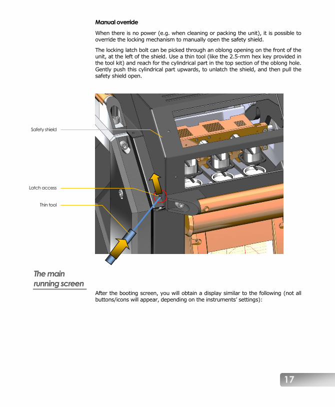
Manual override
When there is no power (e.g. when cleaning or packing the unit), it is possible to override the locking mechanism to manually open the safety shield.
The locking latch bolt can be picked through an oblong opening on the front of the unit, at the left of the shield. Use a thin tool (like the 2.5-mm hex key provided in the tool kit) and reach for the cylindrical part in the top section of the oblong hole. Gently push this cylindrical part upwards, to unlatch the shield, and then pull the safety shield open.
The main
running screen After the booting screen, you will obtain a display similar to the following (not all buttons/icons will appear, depending on the instruments’ settings):
Safety shield
Latch access
Thin tool

18
Here is a short explanation of the various zones and buttons:
The graph zone shows the outline of the crucible temperature as a function of time.
The “Start” button, quite obviously, is used to launch the currently selected fusion program.
This button is used to unlock the safety shield (see Operation of the safety shield, page 16).
This “sleep” button allows the user to put the fluxer in smooth shutdown mode. Pressing it will turn the heating power off but keep the furnace door closed, so that the furnace cools very slowly. This can help extend the life of the insulation.

19
This activates the sample tracking screen. See Introduction to data logging at page 71 for more details on how to use this feature.
The “tilted crucible” icon/button is used to tilt the crucible holder a bit, for easier insertion of the crucibles into the holder. Press again to re-straighten the crucibles.
The crucible temperature icon is depicted with
• the actual measured temperature (in orange), and
• the target temperature, which the crucible heater is in the process of reaching (in gray)
The “ramping” icon informs on the rate at which the current target temperature is to be reached.
When turning the instrument on, this will always show “Fast”.
The “beaker loading” icon is used to temporarily make the platinumware holders swing backwards, in order to easily place the solution beakers in their holes.
The “parameters” button is used to adjust the individual setting of each program step. More details are given at page 32, Programming the X-300 (advanced).
This zone is used to select the current program. Click on the arrows or on the method number to switch to a recipe selection screen.
Clicking on the recipe name itself will allow you to rename it. More details on this are given at page 37, Managing fusion methods.

20
The Copy button is useful to duplicate an existing program, to create a derived recipe. More details are given at page37, Managing fusion methods.
The Delete button is used to erase a program from memory. More details are given at page 37, Managing fusion methods.
The Save button is used to write the current program and its parameters into memory. More details are given at page 37, Managing fusion methods.
The Global Parameters button is used to access a screen where general configuration settings can be modified. More details are given at page 43, Global parameters.
The padlock icon/button shows the state of the fusion recipe parameters.
A closed padlock means that the parameters are locked, and a password is required to unlock parameter access. Conversely, an open padlock means that all parameters can now be freely changed.
More details are given at page 32, Programming the X-300 (advanced).
Entering the password is also required to modify the parameters of the Global parameters screen.
Loading a
program Changing the current program can be done in several ways.
• Touching the program number will call the program selection screen.
• Touching the left or right arrows on either side of the program name will also call the program selection screen, but will also decrease/increase the program number.
• In the program selection screen, you can use the left or right arrows to scroll among the proposed programs, or you can directly select the desired program by touching its name.

21
Touch the green button to confirm, or the red to cancel.
During a fusion While the instrument is running, the main screen will display additional information and buttons, as well as a general estimated timer showing the total time remaining to the fusion program.
Here is the explanation of the additional graphical elements. (Other icons were explained at page 17, in The main running screen section.)
Cancel
Accept
Preset
methods

22
The Pause button is used to temporarily “freeze” the ongoing fusion.
In pause mode, timers are suspended, and the current furnace temperature is maintained. Any ongoing motor motion will be continued or completed. This can be useful when some extra time is required to complete an oxidation or dissolution reaction, for example.
Press the Pause button again to resume normal operation.
This cluster represents the elapsed time (mm : ss) since the requested temperature is attained, as well as the currently-running step number (in red).
See page 30, Description of the fusion steps, for more information on this topic.
The Stop button, as the name implies, is used to halt an ongoing fusion process, stopping all motors.
This can be used when one realizes that the crucibles or molds are not properly prepared, or in case of emergency,
for example.
• Pressing Stop again will cancel the ongoing program and reset the instrument.
• Pressing Start instead will resume the fusion program.
The right
ingredients From the preceding paragraphs, we already know how to launch a fusion program. There are, however, a few other things than one should know to obtain a perfect disk. These include:
1. properly preparing the sample for the fusion,
2. selecting the appropriate flux blend from the sample type,
3. determining the total mass in the crucible from the mold capacity,
4. estimating the flux-to-sample ratio,
5. using the appropriate additives, and
6. mixing the components together.
Sample preparation
Besides the traditional requirements for a sample to be representative, uncontaminated and dry, Katanax recommends that the sample be ground to <100µm. This is to ensure that the fusion be completed within a reasonable time.
Additionally, the sample must be fully oxidized before heating the crucible containing the sample.
23
IMPORTANT: Heating a sample containing metallic species at high temperatures will cause an alloying reaction, damaging the crucible, and possibly damaging the instrument.
Flux blend
Typical fusions use a mix of lithium metaborate (LiM) and lithium tetraborate (LiT). Lithium metaborate alone typically offers a better sample solubility, but can lead to crystallization of the bead. Tetraborate stabilizes the glass, but may limit solubility for some samples. Thus, to optimize solubility and obtain stable glass disks, one must use the correct LiT/LiM flux ratio.
The mixing ratio is determined chiefly by the acidity of the sample. Acidic samples require a basic flux (more LiM), while alkaline samples need an acidic flux (more LiT) and neutral samples call for neutral flux (50% LiT + 50% LiM).
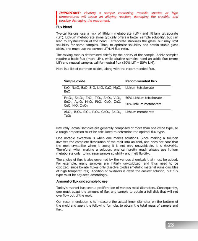
Here is a list of common oxides, along with the recommended flux.
Simple oxide Recommended flux
K2O, Na2O, BaO, SrO, Li2O, CaO, MgO, BeO
Lithium tetraborate
Fe2O3, Sb2O3, ZrO2, TiO2, SnO2, V2O5, SeO3, Ag2O, MnO, PbO, CoO, ZnO, CuO, NiO, Cr2O3
50% Lithium tetraborate –
50% lithium metaborate
Al2O3, B2O3, SiO2, P2O5, GeO2, Sb2O3, TeO2
Lithium metaborate
Naturally, actual samples are generally composed of more than one oxide type, so a rough proportion must be calculated to determine the optimal flux type.
One notable exception is when one makes solutions. Since making a solution involves the complete dissolution of the melt into an acid, one does not care that the melt crystallize when it cools; it is not only unavoidable, it is desirable. Therefore, when making a solution, one can pretty much always use lithium metaborate only, to increase sample solubility and melt fluidity.
The choice of flux is also governed by the various chemicals that must be added. For example, many samples are initially un-oxidized, and thus need to be oxidized; since borate fluxes only dissolve oxides (metallic material ruins crucibles at high temperatures). Addition of oxidizers is often the easiest solution, but flux type must be adjusted accordingly.
Amount of flux and sample to use
Today’s market has seen a proliferation of various mold diameters. Consequently, one must adapt the amount of flux and sample to obtain a full disk that will not overflow out of the mold.
Our recommendation is to measure the actual inner diameter on the bottom of
the mold and apply the following formula, to obtain the total mass of sample and flux:

24
Total mass [g] = (Mold diameter [mm])²
150
Thus, for a 32-mm inner diameter mold (recommended diameter), we obtain 32² / 150 = 6.827 g, which we can round up to 7 g.
This being said, there are also molds on the market that are very shallow (despite the thickness of the metal they are made of). Those molds will require less flux to fill correctly, but using the right amount of releasing agent and properly leveling the mold are more critical.
Flux-to-sample ratio
After the choice of the right flux, the flux-to-sample ratio is probably the second hardest question to answer. This section intends only to explain general concepts. For more specific information, the customer is invited to contact Katanax directly.
To obtain the best readability possible on the analytical instrument, one wishes to put as much sample as possible in the preparation. However, putting too much sample will not only take considerably more time to dissolve, but also over-saturate the flux, and leave undissolved sample particles in the disk.
The solubility of samples into the flux being rather hard to predict theoretically, it is recommended to work with the following method:
1. Determine the optimal flux type. If unsure, 67% LiT with 33% LiM is a good starting point.
2. Using the formula above, calculate the total amount of flux and sample required for your mold size.
3. From this mass: weigh 5% sample for 95% flux, directly in the crucible. Mix thoroughly.
4. Proceed with fusion, and observe the result.
5. If the bead is perfectly homogenous, it is possible to try increasing the amount of sample a little.
6. If the bead is milky or dusty (presents tiny particles of undissolved sample), try again with less sample, or change the flux type a little. It is also possible that the sample be not completely oxidized. Just after weighing the sample (before adding the flux), add a small amount of solid oxidizer, liquid acid or liquid base, depending on what reacts better with the sample at hand.
The optimal flux-to-sample ratio is found when all the sample is dissolved, and almost saturates the flux solvent in a reasonable time.
Note that increasing fusion temperature does not allow the stable dissolution of more sample. It may quicken the dissolution speed, but when the disk will cool down, a precipitate will appear, or the disk will be prone to spontaneous bursting.
The non-wetting agent (NWA)
The non-wetting agent (NWA) acts as a surfactant that makes the melt less prone to sticking to platinumware. Non-wetting agents are halogen compounds (generally containing Iodine, Bromine or Fluorine) and typical formulations include

25
KI, LiI, LiBr and NaI. Only a few milligrams are required. If in doubt, use about 30 mg of Libr and observe the results. Ammonium iodide (NH4I) is not recommended, as its decomposition temperature is too low.
We strongly recommend using such a non-wetting agent, to lengthen the mold’s life expectancy, and to ensure all the melt is transferred into the mold upon pouring. The NWA may be added in solid (powder) form, or as an aqueous solution.
Katanax also sells flux blends that contain predetermined amounts of non-wetting agent. Please contact Katanax to obtain this time-saving product.
Oxidizing agents
As previously mentioned, it is of key importance that the sample be oxidized. While it is often safer and easier to oxidize the sample using a liquid acid or base before fusing, it is also possible to use powder reagents to oxidize the sample in a one-step operation.
Typical oxidizers are lithium carbonate (Li2CO3, which reacts at around 700-
800°C), lithium or strontium nitrate (LiNO3 or Sr(NO3)2 which react at around 500-700°C) and lithium peroxide (Li2O2, which reacts at around 300-500°C). Several minutes at the reaction temperature must be allowed before heating up further, and temperature ramping can be useful to avoid spills due to too fast a reaction (see page 32, Programming the X-300 (advanced) for details on ramping). The amount of selected reagent will depend on the sample contents and can be estimated stoichiometrically. An excess of oxidizer is recommended, but that may require adjusting the flux mixture.
Manual mixing
Once all the components are selected and weighed into the crucible, some manual mixing is recommended, to improve contact between the various reagents.
In particular, very fine sample particles have been observed to agglomerate, and a manual mixing will help breaking the lumps that might have formed during and after weighing.
Two notable exceptions to this general rule are high-carbonate samples and when using powder oxidizers. In those special cases, one want to first lay some flux on the bottom of the crucible, then add the sample (and oxidizer) on top. Manual mixing would ideally just be done with the sample and oxidizer, because one wants to have the most intimate contact between the sample and the oxidizer. Flux will merely act as a shield at first, protecting the crucible from alloying with the sample. In the case of high carbonate samples, it is best to lay the sample on top of the flux and not mix; the expelled gases will escape more freely.
Care of the
platinumware Crucibles and molds should be considered an integral part of your fusion machine.
As such, care must be taken to ensure that they are free from leftover flux, molten or in powder. If need be, you can use citric acid or hot 20% HCl (and proper precautions) to clean them. Depending on the amount of deposit, cleaning time can range from several minutes to a full night.

26
It is also important that the crucible’s and mold’s interior surfaces be kept polished, to ensure a smooth melt pour, easy bead removal and good analytical results. Katanax offers a versatile polishing kit (p/n KP9004A or KP9005A, for 115 V or 230 V respectively) comprising a set of very fine diamond pastes with a rotary tool fitted with various soft buffing pads. Contact Katanax for details.
Finally, crucibles and molds are quite fragile and can distort over time. Re-shape these items without delay to restore their original dimensions. Avoid hitting the mold on the table to remove the bead ! You may use a suction cup or an identification sticker to pull the glass bead while keeping track of the bead’s ID.
With proper care and fusion method, a crucible can be expected to last for several hundred fusions, while molds typically last longer with proper use of non-wetting agents.
Crucible
installation Once the crucibles are filled with the proper components, they can be installed in the fluxer, one at a time.
To install a crucible:
1. Make sure that the crucible holder hoops are horizontal. It is normal that the fork’s top and bottom bars be slanted.
2. Simply tilt the crucible’s top towards the left (i.e. counterclockwise) and insert the crucible into its holder, between the top bar and the hoop.
Top bar
Hoop
Bottom bar
Crucible
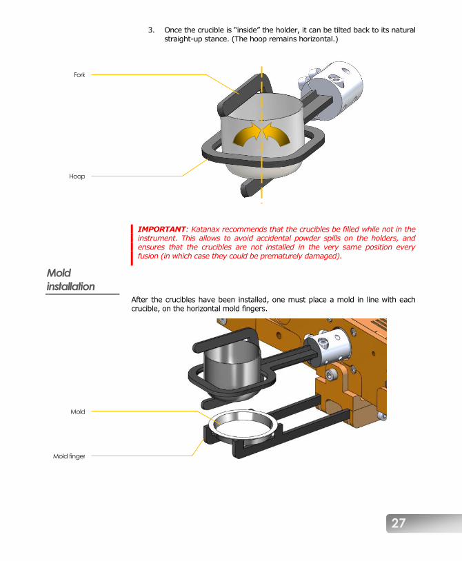
27
3. Once the crucible is “inside” the holder, it can be tilted back to its natural straight-up stance. (The hoop remains horizontal.)
IMPORTANT: Katanax recommends that the crucibles be filled while not in the instrument. This allows to avoid accidental powder spills on the holders, and ensures that the crucibles are not installed in the very same position every fusion (in which case they could be prematurely damaged).
Mold
installation After the crucibles have been installed, one must place a mold in line with each crucible, on the horizontal mold fingers.
Hoop
Fork
Mold
Mold finger

28
IMPORTANT: Forgetting to install the molds will cause the crucibles to pour the hot molten glass onto the instrument. In such case, no damage will occur, but sample will be lost.
NOTE: If you find that your molds do not fit properly in the fingers, then maybe the fingers are not configured for your mold size. Please refer to page 58, Mold holder configuration, assembly and alignment for details, for details on how to re-configure your mold finders to accept your mold size.
A general
fusion Here are the steps required to perform a fusion on the X-300 fluxer.
1. Turn the instrument on by flipping the rocker switch at the back of the instrument. The main screen appears and the platinumware holders are
automatically pulled out of the furnace. Furnace heating is automatically turned on, to reach the stand-by temperature.
2. Check crucible and mold holders for possible flux spills from a previous fusion. (See page 50, Flux spillage on holders for details.) If holders look vitreous and dirty, clean the holders immediately; do not start a fusion process with dirty holders, as this could damage the instrument.
3. Select the desired fusion program, by clicking on the left and right arrows that flank the current program name.
4. In the platinum crucibles, weigh the required amount of flux.
5. Add the sample by weighing it directly into the crucibles on top of the flux. Mix if no solid oxidizer is to be used and the sample is low in carbonates.
6. Prepare solid oxidation, if required.
6.1 Add a suitable solid oxidizer (generally, a nitrate or carbonate) in the crucibles.
6.2 Mix thoroughly with the sample. (Try to leave the bottom layer of flux untouched.)
7. Add the non-wetting agent if it is not already integrated within the flux. Solid non-wetting agent should be thoroughly mixed with the flux. Making an aqueous solution with the solid salts can also prove very convenient, and can be pipetted on top of the dry ingredients.
8. Place crucibles in the holders. Important: make sure that they are properly installed. See page 26, Crucible installation, for details.
9. Place molds on their holder. Important: do not forget to install a mold under each crucible. See page 27, Mold installation, for details.
10. Close the safety shield, which will lock automatically. See page 16, Operation of the safety shield if you need to re-open the safety shield at this time.
11. Touch Start to launch the fusion. If the preset temperature is not yet reached in the furnace, a few minutes’ delay will allow sufficient heating, then the holders will automatically enter the furnace. The furnace door opens and closes automatically.

29
12. Upon heating, the sample reacts if an oxidizer is present. Then, the flux melts and dissolves the sample. The mold is heated at the same time. At the end, the door opens to let the crucibles out, and those are tilted to pour into the molds. A blower cools the disks.
13. At the end of the cycle (when the cooling blowers turn off), carefully pick up the glass disks. Do not tap the molds on a hard surface to remove the beads, as it will warp the molds in the long run. You may use an identification sticker to pull the bead from the mold. Important: Molds and beads may still be very hot at the end of the cycle, depending on the mold weight and program parameters.
Making
solutions
IMPORTANT: Before attempting to make solutions, it is important to remove the mold holder fingers, which can otherwise interfere with the top of the beakers.
IMPORTANT: Katanax does not recommend attempting to prepare solutions in a fluxer not fitted with the optional solution magnetic stirrers.
When making a solution, the process is quite similar to making glass disks, but the mold installation changes for the following:
9. Place beakers in instrument.
9.1 Completely remove the mold holder fingers by removing the screw and spring at the front of each mold holder support bracket. (See page 57, Mold holder removal for details.)
9.2 Fill PTFE beakers with about 100 ml suitable dilute acid. (10% nitric acid is commonly used.)
9.3 Add one magnetic stirring bar in each beaker.
9.4 Press the “load beaker” button to swing the platinumware holders backwards.
9.5 Put the beakers on the agitator, in their respective holes. The magnetic agitation system is always active, so the swirling motion should be taking place in the beakers.
9.6 Optionally, you can now press the “load beaker” button again, to move the platinumware holders to the front.
A parameter in the pouring step can be toggled to indicate a “solution mode”. This will automatically slide the holders in “load beaker” position immediately after pouring, thus keeping the holders away from the vapors produced by the hot acid.
The fluxer beeps when the beakers are ready to be picked up.

30
Description of
the fusion steps All fusion programs in the X-300 are built the same way, and have nine (9) steps. Here is the list of those steps, along with the corresponding icon:
Heating 1
Typically used to pre-heat the sample, with little or no agitation.
Heating 2
Typically used to oxidize the sample at low temperature (e.g. using nitrates), with little or no agitation.
Heating 3
Typically used to oxidize the sample at higher temperature (e.g. using carbonates), again with little or no agitation.
Heating 4
Typically used to melt the flux.
Heating 5
Typically used to dissolve the sample in the flux with a vigorous agitation.
Heating 6
Typically used to de-gas the melt, for a short time at low agitation speed and high rocking amplitude.
Pouring
Used to transfer the crucible contents into a mold or beaker.
Not used for some preparations, with peroxide fluxes for example.

31
Cooling 1
Used for natural-cooling of the mold, or stirring of the solution
Cooling 2
Used for blower-cooling of the mold
Each step is launched when the preceding one is completed. It is also possible for a step to have a null duration (i.e. zero seconds), and would simply be jumped over. Most fusion programs will not use all heating steps.
Note that all heating steps (1 to 6) are identically structured and could be used interchangeably.
Also, some of the steps have built-in on/off switches that allow extra actions to be executed, or sometimes to turn off the step itself (e.g. pouring step).
Manual edition of step parameters is the subject of the next chapter.

32
Programming the X-
300 (advanced) When specific sample types do not seem to be easily processed by a preset fusion method, it is necessary to manually modify the parameters of critical fusion steps.
Viewing the
fusion
parameters Without risking changing a parameter, any user can look at the values and settings of the current program, step-by-step. This is done by pressing the “Settings” icon, in the lower left corner of the main running screen.
The Settings icon allows to toggle to a screen where the parameters for a given fusion step are displayed. Nothing can be changed unless the advanced mode is unlocked (see page 36, Unlocking the advanced mode).
The screen will now look something like this:
Let us now understand the meaning of each symbol.

33
We are now familiar with the graph zone, which shows the outline of the crucible/mold temperature as a function of time.
The fusion step being edited is represented as the portion of curve between the two vertical red lines.
The large crucible with red thermometer represents a heating step, and the numeral “4” indicates that we are now viewing the parameters of step “Heating 4”.
The Left and Right arrows are used to scroll among the steps of the current program.
The small crucible with red thermometer icon is placed just besides a cell where the target crucible temperature is displayed. (The Minus and Plus buttons will be used to change the parameter.)
The stopwatch icon is placed just besides a cell where the step duration is displayed. Note that step durations are calculated after the required temperature is reached.
The stopwatch with arrow icon is placed just besides a cell that indicates how the target temperature will be reached.
Most fusion applications can use the “Fast” setting, but oxidation steps often call for a slow heat-up rate. This is called “ramping”.
The crucible with angle symbol is used to refer to two rocking parameters.
The top one is the amplitude of the rocking.
The bottom one is the rocking speed.

34
The icon in the lower left corner has now switched to a graph icon.
Pressing this button will bring you back to the main running screen.
If we scrolled fusion steps towards the right, until we reach the pouring step, we would obtain a screen similar to the following:
Icons and symbols have the following meaning:
The large crucible pouring into a mold shows that we are now viewing the Pouring step parameters.
This block of icons shows that the pouring is set to On (thus the “green light”).
The parameters to the top right show the crucible angle upon pouring (in degrees), as well as the pouring motion speed (in percent).
The bottom line shows the current parameters for the final shaking of the crucible after pouring.

35
This icon switch provides the user with the possibility to configure a fusion method as a “solution-making” method, and when turned on, will automatically position the holders in optimal location for beaker loading/unloading.
This block represents the settings of the “shaking” feature. After the pouring action, one can program the crucible to shake up and down for a number of times at a given amplitude.
Again, scrolling to the next step will show us the available parameters for the first cooling step.
And we now recognize the duration parameter, as well as the crucible tilting angle and motion speed. The two crucible-related parameters are used to control the straightening up of the crucible holder. There is typically no rocking motion available in this step, except if the pouring was previously turned off; the system would then assume that the user wishes to perform a “non-pouring” fusion (e.g. pyrosulfate and peroxide).
The next and final step is another cooling step, with special “sub-parameters” for fine-tuning the bead stability (not critical in most cases):

36
The three rows (1, 2 and 3 on the right-hand side) allow the user to optionally set three distinct fan speeds (in percent) and corresponding durations. This permits special “quenching” operations; most fusion users do not need to use those and will simply set zero-durations for two of those sub-steps and 100% fan power for a few minutes in the last one, as in this example:
Note on the tilting angles during cooling
Typically, the tilting angle of “Cooling 1” will be the same as the pouring, and the tilting angle of “Cooling 2” will be ninety degrees (90°) to prevent residual drops from sliding on the outside wall of the crucible, or fall onto the cooling bead. This will give some time for the flux to pour completely out of the mold during “Cooling 1”, while partially straightening the crucibles when the blower starts at the beginning of “Cooling 2”.
Unlocking the
advanced
mode Before being allowed to manage fusion program and edit parameters, one must enter the correct password. To do so, click on the padlock icon/button.

37
After touching the padlock button, a numeric keypad will pop up, ready for password entry.
Type the password, which is 2014.
If you make a mistake while typing, press the backspace button to clear your entry.
If you summoned the numeric keypad by error, you can close it by pressing the locking padlock icon.
Once the password is correctly typed, press on the unlocking padlock icon to confirm. The numeric keypad will
close, and the padlock icon will now be displayed as unlocked.
This icon informs you that you can now modify the fusion program parameters, but also manage the fusion methods (i.e. copy, delete
and save). You are now in “advanced mode”.
NOTE: It is not possible to modify the parameters in the preset programs, and so even entering the correct password will not "unlock" the padlock icon. However, the instrument remains in "advanced mode", and so switching to a custom fusion program will “unlock the padlock” and allow parameter edition.
To close the advanced mode (i.e. “re-lock” the padlock), simply click the padlock icon and then press on the “locking padlock” icon on the keypad.
Managing
fusion methods Fusion methods can be managed just like files on a computer. In the main screen, you can press the icon corresponding to Copy, Delete and Save. Note, however, that the “advanced mode” but first be accessed in order to perform any of the following actions.
Copying
The Copy button is useful to duplicate an existing program, to create a derived recipe. Hence, begin with a preset program that is close to the sample type you want to process, and then you will be able to fine-tune the parameters to suite your specific sample. After clicking on
the icon, a window will ask for a confirmation. Click “Yes” to proceed, or “No” to cancel.
Renaming
Once a method is copied, you will be automatically brought into that copied program, named “Untitled”. We suggest that you immediately rename this with some name that is relevant to your application. To rename the program, click on its name (in this case, “Untitled”), and a full keyboard will pop up. (Note that renaming a preset program is not allowed.)
Deleting
The Delete button is used to erase a program from memory. Once a program is erased, it frees the corresponding memory slot, and it

38
cannot be recovered. Furthermore, preset programs cannot be deleted.
Saving
The Save button is used to write the current program and its parameters into memory. This icon will appear automatically when the user changes a parameter value or a setting in a program. Otherwise, the icon is not shown.
Preparing a
fusion program To build your first fusion program, you must first select a preset program template that will be used as a starting point to design your own program. In most cases, the Oxide program is a good all-around program. Copy it under your desired name, as described above.
Once this “editable” program exists, you can adjust parameters to suit your sample.
Heating steps Heating steps all have the same structure. Hence, if you need only two temperature plateaus, you could use Heating 1 and Heating 2, or Heating 1 and Heating 3, and so on, without affecting anything. For standardization purposes, Katanax tends to use the last heating steps, and leave the first ones empty when not needed.
Temperature
Furnace temperature can be adjusted by pressing on the plus and minus buttons besides the crucible temperature icon.
Note that he X-300 firmware prevents the user to create a decreasing temperature. The instrument will prevent a heating step from having a temperature that is lower than an earlier step. Also, the instrument will automatically increase temperatures of subsequent steps to match the step being edited.
Examples:
Suppose that we have a program with Heating 2 at 500°C and Heating 3 at 700°C. You will not be allowed to decrease Heating 3 below the temperature of Heating 2, i.e. 500°C.
Now suppose that the program has Heating 1 at 900°C and Heating 2 also at 900°C. If you increase temperature of Heating 1, the temperature of Heating 2 will be automatically increased by the same amount.
User is advised that too high temperatures can lead to analytical problems, due to evaporation of the flux.
Katanax does not recommend exceeding 1050°C when using lithium borates.
Katanax does not recommend exceeding 1000°C when using sodium borates.

39
Heating above those temperatures could cause flux evaporation that could bias the subsequent analysis.
A warning will appear when going over 1100°C. Please contact Katanax if you feel that your sample type needs higher temperatures, so that we can assist and develop a lower-temperature method.
Duration
Step duration (mm : ss) is also adjusted by pressing on the plus and minus buttons. The actual step timer will start once the furnace
has reached the temperature set for this step. Hence, the length of a step is actually the sum of the time required by the furnace to increase up to the step temperature, plus the duration parameter. For each step, the duration parameter is limited to 19 minutes and 55 seconds, except if ramping is in use (see below).
Ramping
The ramping parameter determines how fast the furnace will increase its temperature to reach the one set in the current step. In most application, we want the furnace to heat up as
fast as possible, but it is also possible to set this parameter (by pressing on the plus and minus buttons) to limit the heat-up rate. The other ramping values (besides Fast) are given in °C/minute.
Slow heat-up rates are particularly useful with a solid oxidizer, when we want it to react slowly over a temperature range, of typically about 100°C.
Crucible rocking speed and amplitude
The crucible content is mixed by a back-and-forth rocking motion, whose amplitude (in degrees) and speed (in % of the max) can be controlled by means of the plus and minus buttons.
Typically, initial heating steps call for very little rocking. This allows for the oxidizer to react, and for flux to melt without risking overflowing from the crucible (molten flux takes up less volume than powder flux).
When the flux is completely dissolved and pouring approaches, speed and amplitude can be used more generously. One exception would be with samples containing gases. Those samples produce bubbles that can remain trapped in the melt, and de-gassing the melt is sometimes better achieved with very slow speeds and large amplitudes, before pouring.
Pouring step The pouring step occurs when the crucible is tilted forward quickly, to empty its contents either into a mold or a beaker containing acid. However, pouring can be turned off altogether, for those fusion types where pouring is not desired: fusions in sodium peroxide or potassium pyrosulfate.

40
Basic pouring parameters
Pouring can be completely turned off and on by pressing the red and green vertical switch.
If pouring is on, the crucible tilting angle and speed can be controlled with the plus and minus buttons.
Generally, a pouring angle of 120° with a speed of more than 30% works
well. Adjustment is sometimes required to adapt to melt viscosity and mold size.
Crucible shaking
In some cases, a droplet will remain stuck inside the crucible. Once cooled, it can easily be pinged off. However, in some instances, one
wishes to completely transfer the melt out of the crucible. This is mostly done with the help of non-wetting agent, but can also be helped with a mechanical shaking of the crucible after pouring.
The shaking feature is activated by setting the number of shaking motions (1x to
25x) and the shaking amplitude (1° to 20°). Press the right half of the button to increase the parameter, or the left half to decrease. Setting those parameters to zero will cause no shaking.
Cooling steps The cooling process is normally divided into two distinct steps. The first cooling stage (Cooling 1) is a natural-convention cooling, that is, without any forced airflow. This allows for the melt to completely fill the molds while the molds are as hot as possible, and is of key importance in the stabilizing of the melt.
Indeed, in most cases, if one were to start the forced air circulation immediately after pouring, the bead would not cool down uniformly, and residual thermal stresses would remain in the solid disk. This can cause hazardous bursting of the produced disk, in the next minutes, hours or even days.
On the other hand, and again there are exceptions, if the blowers were to start too late (Cooling 2), a crystallization reaction could occur if the molecules have enough time to arrange in an orderly fashion. Crystallization reaction cause the transparent melt to become milky-opaque, typically from the edges towards the center of the mold, pushing the still-liquid melt to the center and upwards as crystallization progresses, thus creating a volcano-like structure. Therefore the challenge resides in finding the correct time for still-air cooling (Cooling 1), and then the blowers can start and work until the molds are comfortably cool to the touch. Hence, the duration parameter is very important, especially for “Cooling 1”.
Duration
Step duration (mm : ss) is adjusted by pressing on the plus and minus buttons. Generally speaking, a “Cooling 1” duration of

41
one to two minutes is a very good starting point. Thereafter, “Cooling 2” can be set for as many minutes as needed, and this parameter will be roughly proportional with the combined weight of the melt and mold.
Special cooling profiles
Some advanced fusion users like to start cooling the bead with forced air immediately after pouring, until it starts solidifying; then, they will let the bead rest in still air for a short while, and complete with another fan cooling step. This is done to shave off a few minutes from the fusion length, and/or to help stabilize the glass.
This kind of exotic cooling profile can be achieved via the three sub-steps of the last cooling step:
The example above represents a “standard” cooling profile, but one could want to start the fans, then stop, then re-start, with complete control of the power (in percent) and time for each of the three sub-steps.
Crucible position after pouring
In a typical cooling step, the two crucible-related parameters are not used to control the crucible rocking motion, but rather to
control the straightening up of the crucible holder, after the pouring.
Typically, the tilting angle of “Cooling 1” will be the same as the pouring (typically 120°), and the tilting angle of “Cooling 2” will be ninety degrees (90°) to prevent residual drops from sliding on the outside wall of the crucible, or fall onto the cooling bead. This will give some time for the flux to pour completely out of the mold during “Cooling 1”, while partially straightening the crucibles when the blower starts at the beginning of “Cooling 2”.
Note that, if pouring is turned off, then the fluxer is in “non-pouring” mode, and so will allow for rocking at this step, just like a normal heating step. This is useful to spread the melt onto the crucible walls when making peroxide or pyrosulfate fusions.
On-the-fly
editing During a fusion, it is also possible to edit parameters on the fly, that is, while the fusion program is running.
To do so, simply edit parameters as explained in the previous paragraphs (from page 32 onwards).

42
Note, however, that there are logical limitations, and the firmware will automatically limit the accepted parameter range to prevent nonsensical or error-causing combinations. All parameter modifications will take immediate effect. If the step of modified parameters has already been executed, the modified parameters will have of course no effect on the current execution. They will only affect the next fusion cycle.

43
Global parameters In addition to recipe-specific parameters, your fluxer provides extra versatility through flexible parameters that will apply to all fusion programs.
To modify the global parameters, first unlock the advanced mode (see page 36, Unlocking the advanced mode), then touch the Global Parameters icon that is now available on the main display screen.
Language In the global parameters page, you can change the instrument’s interface language by selecting your preferred language in the list.
Holding
temperature
offset In order to keep the furnace up and ready for the next fusion, the instrument can maintain power to the furnace to keep it hot. This will help skip the initial ramping time, thus quickening fusions and increasing sample throughput.
In the global parameters screen, you will find a slider for “Holding temperature offset”. Indeed, the holding temperature will be calculated based on the Step 1
temperature, plus or minus the global parameter offset.
Example:
In your fusion program, you have set Step 1 with a temperature of 700ºC,
and the global parameter for holding temperature offset is +50ºC. Then, no matter how the parameters for the rest of the program are set, the furnace will maintain a temperature of 700 + 50 = 750ºC once the fusion is complete.
The offset can be positive or negative.
Using a positive offset, say +200ºC, will prepare the furnace to receive the room-tempered platinumware holders at the beginning of the process. Indeed, a temperature drop in that order of magnitude is typically observed when the door opens and the swing motion system moves the platinumware holders into the furnace.
On the other hand, using a negative offset will save energy and increase furnace life.
Keep in mind that the holding temperature depends on the fusion program currently loaded on the interface screen. Changing the fusion program could therefore change the holding temperature (because all fusion programs do not necessarily have the same temperature set at Step 1).
When the instrument is turned on, the furnace will automatically be activated to reach the holding temperature.

44
Startup
tolerance Basically, when you start a fusion, the crucibles will enter the instrument only once the furnace has reached the calculated holding temperature (based on the temperature of Step 1 and the selected offset value). Therefore, there may be a delay when you press Start, to allow for the furnace to heat up or cool down to the holding temperature.
The user can, however, set a range of permissible temperatures, in which the crucibles are allowed to move in the furnace. This is called the startup tolerance.
Using two sliders, you can configure the blue upper
and lower limits (relative to the red main offset) between which you will permit the holders to enter the furnace. You can set independently the upper limit (called Max: [20 to +200]) and lower limit (called Min: [-200 to -20]), and the platinumware
holders will be allowed to enter the furnace at the beginning of the fusion, only when the furnace temperature Tfurnace is:
Tstep1 + Offset + Min ≤ Tfurnace ≤ Tstep1 + Offset + Max
(where Min ≤ -20, and 20 ≤ Max)
Ideally, leaving both min and max at ±20°C (default setting) will ensure the best possible repeatability conditions.
However, in special cases to enhance productivity, one may want to allow a wider temperature range. Examples of such situations include when a particular fusion method starts with a low-temperature oxidation step and ends with a high-temperature pouring step.
End beep When a fusion cycle is completed, the instrument will emit a series of beep
sounds. By default, the fluxer will beep for 5 seconds, but this period can be extended up to one hour in 10-minute increments.
Automatic
shut-off delay When the instrument is idle for a certain period of time, the heating will be automatically turned off, to save energy.
This delay can be changed by the user, depending on the context of use of the instrument. Enter the global parameters screen, and slide the “Automatic shut-off delay” slider to the value of your choice.
45
Safety shield
protection By default, the checking of the safety shield position and locking should be enabled, to maximize protection. However, it is possible to disable this security feature.
WARNING: Disabling the safety shield protection can lead to serious injuries by extreme heat. User is advised that doing so it at the user’s sole responsibility.
Fusion counter In the global parameters screen, there is a read-only parameter that displays the number of fusions since the instrument was built, similar to the odometer on a car.

46
Special parameters This section presents an advanced interface window that can be used to adjust the offset sensitivities of various electro-mechanical sensors on the fluxer.
WARNING: Changing these parameters should only be done by trained personnel. Incorrectly setting these parameters could cause damage to the instrument.
Accessing the
Special
parameters To invoke the Special parameters window, Press on the padlock icon at bottom right of the main screen and enter the following code “2206” followed by the unlock icon.
The following window appears:
Offsets The top section is used to adjust the various mechanical motions.
IMPORTANT: None of the parameters below is actually memorized until the user presses “UPDATE”.
Please contact Katanax is you feel one of the motion offsets needs to be adjusted. These parameters have been factory-set and should require no further adjustment.

47
Loop operation Once set to “ON” (green light), this setting will cause the next started fusion program to be run in endless loops. Right after the last cooling step, the holders will re-enter the furnace and the fusion program will start over.
Pressing the Stop button cancels the Loop operation, and the instrument resumes normal operation. (The “Loop operation” switch then automatically toggles back to “OFF”.)
Movement
testing To check that the parameters entered and sent work correctly, it is possible to start motions independently.
The ̂ ^ ̂button
This button will cause the furnace door to open and the holders to slide/swing inside.
The vvv button
This button will cause the furnace door to open and the holders to slide/swing outside.
The <> button
This button starts the rocking motion using generic, preset parameters.
The C button
This button starts the pouring motion (i.e. it rotates the crucibles forward to the pouring angle).
The U button
This button resets the position of the crucible, to the vertical (loading angle).
Mold fan (on / off)
These buttons start and stop the cooling fan, for testing purposes. This does not change the way the fan works in normal fusion programs.

48
Fusion troubleshooting This section presents the most common fusion-related problems. For specific assistance, please do not hesitate to contact us (see page 84, Contacting Katanax).
Disk cracks Disk cracking occurs when there are internal stresses within the glass bead. The specific causes can vary as follows:
Glass disk sticks to the mold
If disk top surface is concave (disk adheres to the mold walls), add non-wetting agent at the beginning or during the fusion. Katanax recommends lithium bromide.
Glass disk contains undissolved particles
Some sample may not be completely dissolved. Make sure that sample is fully oxidized or decrease amount of sample.
Glass disk is improperly cooled
Generally, cooling a disk too fast can cause its cracking. Allow more time for the still-air cooling (i.e. before starting the cooling blower). Generally, natural cooling (no blower) between 1m and 1m30s should be fine.
Disk crystallizes Crystallization reaction cause the transparent melt in the mold to become milky-opaque during cooling, typically from the edges towards the center, pushing the still-liquid melt to the center and upwards as crystallization progresses, thus creating a volcano-like structure.
Inappropriate flux
Crystallization will occur if too alkaline a flux is used (i.e. too much lithium metaborate). Increase the proportion of tetraborate to compensate. Or, sometimes the solution is to add a bit of sample (e.g.: SiO2).
External contamination
In some circumstances, dirt, dust or other small debris can be sucked into the blower and land onto the glass bead. This type of crystallization will develop from this single point on the surface and radiate outwards. Cleaning the instrument’s base and surroundings will correct the problem.
Incomplete
disk This symptom causes disks that have the shape of a moon crescent, i.e. a circle with a missing section.

49
It is caused by the mold not containing enough flux, by the mold not being leveled or by an excessive amount of non-wetting agent. Add flux or level instrument/mold holder accordingly.
Non-
homogenous
disk When holding the glass disk in front of a light source, if you can observe powdery residues, then some sample may not have dissolved.
Sample is not fully oxidized
As we know, un-oxidized sample cannot be dissolved in flux, and may also cause damages to platinumware. Make sure to use the proper type and amount of oxidizer.
Oversaturation
A fusion being a dissolution reaction, it is perfectly possible to obtain an oversaturated bead. Simply reducing the amount of sample will correct the problem.
Improper grinding
If the sample is too coarse, or if it lumps together easily, then the time allotted by the fusion program might not be long enough.
One can either extend the fusion duration, or grind the sample to a finer granulometry. We recommend smaller than 100 µm. Also, a manual mixing of the sample with the flux can often prevent the lumping issues.
Sometimes, the small “dust” is actually gas (see below).
Bubbles in disk Typical with carbonate samples, this phenomenon exhibits gaseous bubbles that remain imprisoned within the glass disk.
In many cases, simply placing the sample on top of the flux and not mixing will allow the sample to de-gas and thus avoid this problem. However, some samples are known to make lumps and become harder to dissolve if not mixed; if that is the case, then simply allow a period of slow mixing for an extra minute or two, just before pouring.

50
Periodic inspection This instrument requires some regular checking, which is very important to keep your instrument up and running.
Katanax knows that a broken instrument in a laboratory setting causes sample back-up and unnecessary costs. That is why this manual comprises not only a Periodic inspection section, but also a Service operations chapter (see page 56), which guides the user in a step-by-step fashion through operations that sometimes need to be performed on-site.
If unsure, do not hesitate to get in touch with a Katanax technician (see page 84, Contacting Katanax). Assistance by phone or email is always free of charge.
Note that no modifications of the instrument are allowed, except those explicitly described and permitted in this manual. Any undue modification automatically cancels the warranty and could endanger the user's life.
Warning
IMPORTANT: Some of the procedures described in the following pages imply a risk of death by electrocution; those procedures shall be executed only by trained personnel.
Inspection
schedule table Frequency
Checkpoint Description Action
(if problem found)
Page
Every
fusion
Flux spillage on
holders
Check for flux deposits Cleaning 50
1 month or
300 cycles
Holders alignment
and functionality
Check for mis-aligned,
chipped, cracked or broken
ceramic parts
Adjust or replace
damaged parts
51
Furnace chimney cleaning
Check for flux build-up Clean 52
Air filter for the molds cooling
Remove the filter for cleaning Clean 52
3 months
or
1000 cycles
Element terminal
connections
Check for correct tightening
and absence of oxidation
Re-tighten or
replace
53
Furnace cleanliness Check that furnace is clean
and insulation is not cracked
Replace or clean 53
Thermocouple junction
Check junction Replace 54
Swing motion
system
Check proper working, clean,
belt tension, pulley alignment
Adjust,or clean 54
Flux spillage on
holders This procedure describes an easy, yet crucial, step to be completed before each fusion cycle. Flux spillages (residues), if left un-cleaned, can potentially lead to the deterioration of key components of the fluxer.

51
1. This visual inspection should be done every fusion cycle.
1.1 Look for vitrified, darker or colored spots on the ceramics parts that make up the holders.
1.2 In the case that a spillage occurs on one or more parts of the holders, clean or replace immediately.
1.3 See holders section of this manual to remove/replace/disassemble the holders. Be extra careful, as some molten flux may have found its way between components and act as a very strong “glue”.
2. If parts are found to be contaminated with flux deposits, carefully disassemble the parts in question and apply one of the following methods.
3. For cleaning ceramic parts, a mechanical rubbing is typically sufficient. You may use a specialized diamond file, or just another part made of alumina
ceramic. For smaller spills, the following procedure may be used.
WARNING: Do not use these procedures to clean platinum crucibles or molds: it will cause irreversible damage to precious metals.
3.1 In a large container (e.g.: 2 liter Pyrex beaker), mix together a 20% Ammonium nitrate (NH4NO3) solution with a 20% Hydrochloric acid (HCl) solution.
3.2 Put your container on a hot plate and keep the solution warm at 80°C. (The cleaning solution will not work well until 80°C is reached.)
3.3 If your hot plate is equipped with a magnetic stirrer, you can add a magnetic bar in the beaker to agitate the warm solution and accelerate flux dissolution.
3.4 For a small or very recent spillage, 30 minutes to 1 hour should be enough to clean it.
For a larger or older spillage, up to 2 hours could be required.
3.5 In case of large spillages, a diamond disc mounted on high-speed rotary tools (e.g. Dremel™) can be used to remove major parts of spillage and then the solution can be used to finalize the cleaning.
If a rotary tool is used, care must be taken in order not to grind the ceramic part itself.
Holders
alignment and
functionality This procedure describes how to ensure that both the crucible and mold holders are properly positioned, and in working condition.
1. Procedure preparation
1.1 Let the instrument cool down, and turn it off.
1.2 Unplug it from the power outlet.
2. Inspection of the holders

52
2.1 Verify that mold holders are perfectly horizontal. Note that the mold holders are installed on a system that will give them an oblique angle, but should still keep them in the horizontal plane.
2.2 Verify that flux spillage is not present on holders anywhere. (Refer to appropriate section in case flux deposits are found.)
2.3 Verify that crucibles holder(s) is (are) free to rock and pour into the molds, without rubbing or hitting anything. To do so, manually move the crucibles holder to simulate the movement of rocking and pouring.
2.4 Using the appropriate tools, verify that screws that are used to secure the grip assembly for the mold fingers are well tightened.
2.5 Manually swing the holders down to their lowest position, then manually open the door and finally gently push the holders upwards inside the
furnace. Verify that there is no rubbing or undue contact. (Refer to page 58, Mold holder configuration, assembly and alignment for details.)
In the case that an adjustment or replacement need to be done, please refer to the appropriate section of the Service operations chapter (see page 56).
Air filter for the
molds cooling
IMPORTANT: Always disconnect the instrument from the power outlet when working with panels removed. 240 Volts inside! Risk of electrocution!
The air that is drawn through the blowers to cool the molds goes through a filter before actually entering into the unit. This filter will catch medium to large sized airborne particles, and requires periodic cleaning.
1. Pull on the instrument to slide it towards the edge of the countertop. (Be careful not to have its front legs exceed the countertop.)
2. Using a long hexagonal key, remove the front U-shaped aluminum extrusion that makes up the filter frame.
3. Simply pull the fiber filter horizontally towards you, like a drawer, and clean it before sliding it back in place. Cleaning methods include simply shaking it (preferably outside), or blowing it with compressed air, or with a vacuum cleaner. Cleaning under running water is also possible, provided that the filter is completely dry before being re-installed.
4. Re-install the aluminum frame and push the fluxer back in its original location.
Furnace
chimney
cleaning The furnace is fitted with one chimney per position, whose main purpose is to vent out the chemicals that are expelled during fusion. It is advisable to check periodically that the chimneys’ insides are still clean, and to scrub them if needed, as condensed material may build up over time.
53
1. Stand on a small step to look directly down each of the chimneys. Their inside wall should be smooth and solid white.
2. If it is deemed necessary to clean the inside of the chimneys, continue to the next steps.
3. Turn the instrument off and let it cool down.
4. Slowly pull each chimney to remove them.
5. Use a suitable brush or the eraser end of a pencil to scrub any deposit from the inside wall.
6. Carefully re-install the chimneys after cleaning.
Element
terminal
connections
IMPORTANT: Always disconnect the instrument from the power outlet when working with panels removed. 240 Volts inside! Risk of electrocution!
1. To check the integrity of the element ceramic connectors and terminals, do the following:
1.1 Unplug instrument and let the furnace cool down completely.
1.2 Remove the element connection access panel (refer to page 60, Heating element replacement for details on this step).
1.3 Visually inspect and verify that terminals of all ceramic connectors are not overly oxidized. If a faulty connector is found, replace this ceramic connector immediately.
1.4 Using an appropriate tool, verify that all wire terminals of ceramic connectors are well tightened, both on the element side and the wire side. Do not over-torque the screws. Simply verify that they have not become loosened.
Furnace
cleanliness
IMPORTANT: Always disconnect the instrument from the power outlet when
working with panels removed. 240 Volts inside! Risk of electrocution!
1. To run this inspection, instrument must be turned OFF, unplugged and furnace at room temperature.
1.1 Unplug the X-300 and let it cool down completely.
1.2 Remove the instrument’s main cover (see page 62, Top/back panel removal for details).
1.3 The furnace door should be hanging ajar.

54
1.4 Visually inspect the door and furnace insulation. Verify that no parts are threatening to fall or are presenting severe cracks that could impair functionality.
1.5 The “pillar”-shaped insulation part that protrudes from the furnace door is particularly vulnerable to mechanical stresses. Please make sure not to break them as you perform the following steps.
1.6 Using dust mask, gloves and vacuum cleaner, remove all dust from furnace and door. Pay attention not to directly touch the material with the vacuum tube (the material is very fragile and brittle).
1.7 All parts that are found faulty should be ordered and replaced as fast as possible.
Thermocouple
junction
IMPORTANT: Always disconnect the instrument from the power outlet when working with panels removed. 240 Volts inside! Risk of electrocution!
To run this inspection, instrument must be turned OFF, unplugged and furnace at room temperature.
Thermocouple used in instrument is made of platinum-platinum/rhodium (type R) and is normally very durable. In particular, it is impervious to oxidation or damage by heat; only a mechanical incident could damage the junction (i.e. the tip) of the thermocouple.
1. This inspection consists in verifying the junction of thermocouple for visible damage.
1.1 Unplug the X-300 and let it cool down completely.
1.2 Remove the instrument’s main cover (see page 62, Top/back panel removal for details).
1.3 The furnace door should be hanging ajar, so that you can see the thermocouple through the vertical slot opening in the center furnace section. (The thermocouple looks like a thin white ceramic rod coming down at a 45° angle. The actual “thermocouple” is the metal junction at its very tip. A small flashlight may come in handy.)
1.4 Visually inspect the thermocouple junction. Verify that no mechanical shock has occurred, which could have crushed or otherwise damaged the thermocouple junction. If junction is damaged, a new thermocouple should be ordered and installed.
Swing motion
system
IMPORTANT: Always disconnect the instrument from the power outlet when working with panels removed. 240 Volts inside! Risk of electrocution!
To perform functionality verification, do the following:
1. Power ON the X-300 and select a method that does not heat (e.g. “TEST”).

55
2. Access the Special parameters window (see page 46).
3. Press on the “^^^^” button to slide the holders in the furnace.
4. Press the “vvvv” button to slide the holders out of the furnace.
5. Repeat these operations 4 or 5 times to verify that no jerking movement occurs.
6. If jerking or abnormal movement occurs, disconnect the unit from its power outlet, open the sides of the instrument to access the swing motion system, correct the problem, and then repeat this test until problem has been resolved.
7. If movement occurs normally, no adjustment is needed.

56
Service operations This section describes tasks that are performed on a regular basis, and are performed to adjust or repair a malfunctioning system of the instrument.
Some sections also describe initial operations, which need to be performed before first using the unit (e.g. assembling the crucible holder and the mold holder).
Should you have any question, or need further assistance, please do not hesitate to contact us (see page 84, Contacting Katanax).
Note that your unit is able to be remotely diagnosed by Katanax service personnel, with a few configuration steps described in Allowing Katanax support to access your fluxer, on page 82.
Warning
IMPORTANT: Some of the procedures described in the following pages imply a risk of death by electrocution; those procedures shall be executed only by trained personnel. 240 Volts inside !
Crucible
holder removal 1. Remove any crucibles and molds from the holders.
2. The crucible holder is made up of two parts, partially intertwined at about 80°. One ends with two prongs and will be called the “fork”, and one end in a closed square with rounded corners and will be called the “hoop”. If you suspect there has been a flux spillage onto the holder, you will need to remove both (hoop and fork) at the same time, since they may be partially “glued” together in flux. (If that is the case, then skip step 4.2 below, and be careful not to drop fragile parts.)
3. Both the Fork and the Hoop are held in a common aluminum collar, which has five (5) screws. The two screws closest to the wide motor plate are used to
“Fork”
“Hoop”
Aluminum collar
“Hoop” screw
“Fork” screws

57
fasten the collar onto the rocking shafts, and so must not be un-tightened at this point.
4. One must start by removing the Hoop:
4.1 Locate and un-tighten the screw that is all by itself (not in a group of 4). You do not need to fully remove the screw.
4.2 You can now gently pull on the hoop to remove it. Notice that it features a notch where the holding screw was located.
5. Now, let us remove the fork:
5.1 Locate and un-tighten the two collar screws that are closer to the front of the unit. You do not need to remove the screws.
5.2 You can now gently pull on the fork to remove it.
6. Replace or clean any damaged or flux-soiled parts.
Crucible
holder
installation In this section, you will find essential information needed to properly re-install the crucible holder. Please follow the instructions carefully, or pouring issues could occur.
1. Manually rotate the crucible rocking collar, so that its four (4) grouped screw head point upwards.
2. Carefully look at the fork, and you will notice that it is not symmetrical. One prong of the fork has a longer transversal branch. This longer branch goes to the right.
3. Now, fully insert the main stem of the fork in the horizontal slot; remember to keep the longer branch on the right.
4. Tighten the two screws that will compress and hold the fork stem. Make sure to tighten both approximately at the same rate, so as to close the gap uniformly.
5. Now, rotate the collars about 90° counterclockwise. A lone screw head (for the
hoop) should now be pointing upwards.
6. Insert the hoop in its slot, making sure to align its notch with the screw, i.e. towards the right.
7. Gently tighten the hoop screw. Note that the screw should not be compressing anything; it is the threaded body of the screw in the hoop’s notch that will prevent the latter from coming off.
Mold holder
removal Removing the mold holder(s) is required when preparing solutions.

58
1. Remove any mold from the mold holder(s).
2. Notice that each mold holder unit is made up of two long Black Ceramic “fingers”, both fastened to a common aluminum support. This support is in turn fastened to the motor plate by a single screw, which is threaded through a spring, to allow for some movement in case the fragile fingers are accidentally bumped into.
3. Using a hex key, remove the screw shown below, for each position. Be careful not to drop the screw or spring (not shown on picture). This will allow you to remove the mold finger support.
4. Notice that the motor plate is machined with three slanted faces, so that the fingers are expected to go slightly sideways.
5. Carefully store the mold holder(s) until needed again. (Caution: the fingers are sharp and brittle. Do not lose the spring or screw.)
Mold holder
configuration,
assembly and
alignment In this section, you will find essential information needed to properly assemble and align the mold holder assembly.
Introduction to the mold holder assembly
One of the nice features of the X-300 fluxer is the possibility to adapt to various mold diameters without the need for additional holder parts. All that is required is a re-configuration of the mold holder assembly.
The mold holder comprises up to three pairs of “fingers”, designed to accommodate the four common mold sizes (30, 32, 25 and 40 mm). The molds fit between vertical prongs at the free end of each finger. Each of the four prongs is
also cut diagonally, so that fingers are symmetrical two by two (i.e. finger “A” and
Mold holder
support

59
finger “B” are symmetrical). Each such pair of fingers is clamped down at its other end onto the mold finger support, which is in turn fastened to the rocking motor plate with a single screw per mold position.
Please refer to page 57, Mold holder removal, to learn how to remove the mold holders and supports.
Each machined support features one screw per side, which hold the fingers in place. Removing these screws and corresponding “washers” allows to the removal of the mold fingers. Each finger ends with perpendicular prongs; at one end, the prongs are close one to another (“short” end), and they are farther apart at the other end (“long end”).
The “short” end is designed to accommodate the smaller molds (30 and 32 mm), while the “long” end is designed to accommodate the larger molds (35 and 40 mm).
All that you will do in the next section is to fasten the fingers with the prongs pointing upwards, and arranged as illustrated below (viewed from above):
Notice in the picture that the two small molds (in red) are fitted in the “short” end prongs, while the two larger ones (in blue) are in the “long” end prongs. Additionally, the left-to-right position of the fingers is switched between 30 and 32 mm, as well as between 35 and 40 mm. (The 30-mm and 35-mm mold circumferences touch the sharp ends of the prongs’ diagonal cuts, whereas the 32-mm and 40-mm molds touch the prongs’ diagonal flat itself.
30mm 32mm
35mm 40mm
“Long” ends
Mold finger
“Short” ends A
B
A B B A A B B A

60
Installation of the mold fingers on their support
1. Remove the rectangular “washers” from both sides of each mold finger support, to free the fingers. (Be careful: they are sharp and fragile)
2. Based on the instructions in the preceding paragraphs, position the pair of fingers as required for the first mold. (Each finger has a pair of prongs that will be needed to support your mold, and another pair that will not be used for your mold size.)
3. Slide the “unused” prongs, into the sides of the finger support. Place a washer on each side and fasten the screws to hold the fingers in place.
4. Once the first pair of fingers is fastened, you may want to check that your actual mold fit properly in your selected configuration. Place a mold in the fingers’ prongs to confirm (and then remove it).
5. You may now install the joined fingers onto the rocking motor plate. To do so, place the finger support against the rocking motor plate, and then install the screw – do not forget the spring in-between.
6. Tighten the screw until a gentle compression of the spring occurs (about 1-2 turns after the spring begins compressing).
7. If applicable, repeat the above steps with the next finger pair, until all the fingers and their supports are installed.
Heating
element
replacement
IMPORTANT: Always disconnect the instrument from the power outlet when working with panels removed. 240 Volts inside! Risk of electrocution!
There can be up to seven (7) heating elements in the X-300, each individually connected to a ceramic terminal block and then to an independent electronic switch. Each element is composed of a conductive material embedded in a flux-resistant casing.
All elements are located on the furnace top wall, inserted from the front and protruding at the front of the fluxer (behind a metallic partition), where they are fastened into a ceramic connector, outside the furnace cavity.
1. Disconnect the instrument from the power outlet.
Heating element

61
2. While a heating element can be replaced on an X-300 that is still hot (using appropriate protective gloves) Katanax strongly recommends letting the unit cool down completely overnight.
3. Remove the instrument’s top/back panel. (See page 62, Top/back panel removal for details.)
4. Remove the instrument’s LED/safety guard plate (2 screws).
5. To allow for the alignment of the heating element through the two metal sheets and facilitate their removal/insertion, make sure to loosen the two screws of the element stabilizer clamp.
6. Proceed to remove one element at a time.
7. Lower (unscrew) the stopper screw corresponding to the element position you want to remove. Do not completely remove the screw; just loosen it until the threads are lowered flush.
LED/safety guard
Stopper screws
Clamp screws
Stabilizer clamp
Clamp screws

62
8. Loosen the four (4) screws of the ceramic terminal connector.
9. Remove the central screw of the ceramic terminal connector. Support the terminal with one hand to keep it in place.
10. Gently pull the ceramic terminal and the heating element at the same time, horizontally toward the front of the machine.
11. Discard the damaged heating element, and get the new one.
12. Insert the leads of the new element in the matching holes of the ceramic connector. (Do not tighten the terminal screws yet.)
13. Gently insert the new element and the connector at the same time. Fasten the connector firmly in place.
14. Now tighten the connector screws on the element side, while looking into the terminal holes on the other side, and making sure that the element leads are
correctly placed and squeezed by the terminal screws.
15. Now insert the wires in the terminal on the opposite side of the element, and tighten then in the terminal.
16. Tighten the stopper screw corresponding to the re-installed heating element.
17. Repeat steps 6 to 15, until you have replaced all elements that needed to be changed.
18. Now, ensure that all heating elements are fully inserted.
19. Tighten the two screws of the element stabilizer clamp, while pushing downwards on that clamp.
20. Re-install the LED/safety guard.
21. Re-install the top/back panel.
Top/back
panel removal In order to access the furnace and the rocking system, the top/back panel of the instrument must be removed.
IMPORTANT: Always disconnect the instrument from the power outlet when working with panels removed. 240 Volts inside! Risk of electrocution!
1. Disconnect the instrument from the wall outlet.
2. Partially open the safety shield, to just disengage its locking mechanism. (Refer to page 16, Operation of the safety shield, to unlock the safety shield when power is turned off.)

63
3. Locate and remove the screws, as indicated in orange, below. (Four on top, three in the back, and one large on each side.)
4. Remove the top/back panel.
Side panel
removal This fluxer has two sturdy side panels topped with a handle. It is necessary to remove those panels to access the crucible swing mechanism and sensors or motor controllers.
IMPORTANT: Always disconnect the instrument from the power outlet when working with panels removed. 240 Volts inside! Risk of electrocution!

64
1. Disconnect the instrument from the wall outlet.
2. Remove the screws marked below (or symmetrically, if you are remove the other side’s panel).
3. Slide the panel upwards to remove it.
Bottom panels
removal Under the zone where the platinumware holders swing in and out of the furnace, this fluxer has two panels that act as a protective shield for the electronics underneath. It is necessary to remove those panels to access the solution magnetic stirrer, mold cooling blowers and other electronic components.
IMPORTANT: Always disconnect the instrument from the power outlet when working with panels removed. 240 Volts inside! Risk of electrocution!
Front bottom panel
The “front bottom panel” is the one with cutouts for the mold cooling blowers.
1. Remove the top/back panel (optional).
2. Open the safety shield.

65
3. This panel is fastened down by four (4) screws, all accessible through the safety shield opening.
4. Once all screws are removed, slide the panel towards the back of the instrument. (If you removed the front/back panel, then you can take the panel out completely.)
Back bottom panel
In the same horizontal plane as the front bottom panel, but farther back in the instrument, there is a second panel called the “back bottom panel”.
WARNING: This panel is attached to loaded springs, and so removing it requires extra precautions. Please contact Katanax if you feel you need to remove this part.

66
Appendix A –
Technical
specifications Electrical
Voltage ........................... 195-250VAC
Frequency ...................... 50-60 Hz
Electric power ................. 3000 W
Embedded breaker ......... 250 VAC, 15 A
In-wall breaker type ........ 250 VAC, 15 A
(not included)
Physical Weight ........................... 54 kg (120 lbs)
Height ............................ 51 cm (20 in)
Width ............................. 48 cm (19 in)
Depth ............................. 63 cm (25 in)

67
Appendix B – Warranty All Katanax instruments have been carefully inspected and tested before shipping and are warranted to be free from defects in parts, material and workmanship for a period of one (1) year from date of shipment. Ceramic parts may exhibit small cracks developed under heat, and will not be considered defective unless this situation impairs functionality of the instrument. Original heating elements, crucible holder assemblies and mold holders are warranted for a period of six (6) months against defects in parts, material and workmanship; however, damage to these parts by oxidation shall be considered normal wear and does not constitute a defect.
During the warranty period, Katanax guarantees the product against defective workmanship and material, provided the equipment has been installed according to the manufacturer's instructions. This warranty does not apply to any product which has been altered, damaged, tampered with, or subjected to misuse or abuse including substituting parts or accessories of other manufacturers without the written consent of Katanax. Minor adjustments are not covered by warranty.
Katanax disclaims any responsibility for misuse, misapplication, negligence or
improper installation and maintenance of equipment. Katanax makes no warranty or representation regarding the fitness for use or the application of its products by the purchaser.
Katanax is not liable for costs incurred in installation, removal or unauthorized repair of the product or for damage of any type, including incidental or consequential damage.
At its option, Katanax will repair or replace any defects that are exhibited under proper and normal use. Replacement parts are covered for one month after shipping. All customs- and freight-related charges are customer’s responsibility: items returned to Katanax for any reason shall be via freight prepaid, while parts sent to customer will be either sent collect, or shipping charges will be invoiced.
Katanax reserves the right to make changes in the design or to make additions or improvements with respect to its product without incurring any obligation to modify or install same on previously manufactured products.

68
Appendix C –
Firmware and program
transfers Preset
programs This section lists the methods that are factory programmed into the X-300. It is not possible for the user to alter or delete them.
Note that Katanax cannot be held responsible for any damage to platinumware or fluxer incurred by the use of those methods. Especially, samples containing un-oxidized material should be fused with extreme care. If unsure, please contact Katanax. We will be glad to prepare an adapted method for your specific sample.
Name Applicable to... Description
Oxide Cement, glass, ceramics, petrochemical catalysts, most geochemistry samples and general oxides
Most common fusion method. Must only be applied to fully oxidized material.
Metal Samples containing un-oxidized material
Applicable to metals that can be attacked by acids or bases. This method has a low-temperature oxidation period, in which the solid oxidizer attacks the sample. Fusion is then completed like an oxide.
Solution Oxidized material to be analyzed by wet method.
Is normally used with lithium metaborate.
Peroxide Samples containing metals, often precious, which are attacked in peroxide or peroxide fluxes
Low-temperature fusion that does not pour. Crucible is removed with tongs at the end, cooled a little on a metallic surface, then immersed into acid. Platinum crucibles are normally not used with this method, as the flux would damage the crucible.

69
Name Applicable to... Description
Ramping Samples that require slow heat-up slope
Example of the ramping feature. (See page 39, Ramping for details on how to use this feature in your custom-designed programs.)
Backup or
restore by USB Once your favorite methods are developed and optimized, you might want to store them on a USB flash drive, especially before upgrading the firmware of your instrument. This can also be useful to transfer fusion programs among several fusion instruments.
Alternately, you might have received from Katanax a firmware upgrade that you want to install on your instrument.
Backup fluxer to USB drive
1. To start the process, simply insert a USB flash drive into the USB port of the fusion machine. A dialog will automatically pop up, after a few seconds.
2. Touch “Upload”.
3. A dialog will appear, requesting a password and what data to upload. The password is “111111” (six times the digit one). You may have to drag the dialog window to the left, to show the keyboard and then type the password.
4. Select “Upload Project Files” if you want to backup the firmware (i.e. the instrument’s operating system).
5. Select “Upload History Files” if you want to backup the fusion programs’ parameters.
6. Touch “OK”.
7. Now, choose where you want the data to be written. Double-click on “USBDISK”, then click on its sub-directory, named “disk_a_1”.
8. Click “OK” to start the transfer to the USB drive. The screen will black out, and the fluxer will re-boot.
9. The firmware or the programs are now saved, and you can remove the USB drive.
Restore programs, firmware or upgrade firmware
1. If you want to restore a backup that you have made yourself, simply insert the USB drive that contains you backup files, into the USB port of the fluxer.
2. If you have obtained a new firmware by email, extract the directory structure and files you have received in the root directory of a blank USB drive. Then, insert the USB drive into the instrument’s USB port.
3. A dialog will automatically pop up, after a few seconds.
4. Touch “Download”.

70
5. A dialog will appear, requesting a password and what data to download. The password is “111111” (six times the digit one). You may have to drag the dialog window to the left, to show the keyboard and then type the password.
6. Select “Download Project Files” if you want to restore or upgrade the firmware (i.e. the instrument’s operating system).
7. Select “Download History Files” if you want to restore the fusion programs’ parameters. Note that this will erase ALL fusion programs currently stored on your fluxer.
8. Touch “OK”.
9. Now, choose where you want the data to be fetched. By default, you will have to double-click on “USBDISK”, then click on its sub-directory, named “disk_a_1”. If the data was created in another (sub-) directory, you will need
to browse to reach it.
10. Click “OK” to start the transfer to the USB drive. The screen will black out, and the fluxer will re-boot.
11. The new firmware or programs are loaded, and you can remove the USB drive.

71
Appendix D – CPLive :
Data logging Introduction to
data logging This new generation of fluxers has the ability to record fusion data and sample names/codes. This allows for sample tracking, for quality assurance purposes and to aid in diagnosing why a specific sample may not have lent the expected analytical results.
In your X-Fluxer, data logging is turned off by default. Once it is turned on, at each fusion cycle the user will have the possibility to enter a sample identification name or number for each fusion crucible, either via the touchscreen keyboard or with the optional barcode reader.
Then, when the fusion cycle is started, a new log line entry will be created with several information fields such as the date, time, sample names/IDs (if entered), fusion method name and completion status (with error code, when applicable).
This log is stored as individual daily files in non-volatile memory. Up to 40 daily files can be stored, after which the fluxer will automatically overwrite the older file. The files can be retrieved via the USB port with a memory stick, or remotely via the Ethernet port using FTP protocol.
In either case, the files are encoded in proprietary format, which can be converted using a small piece of software called EasyConverter, which converts the raw data into Excel tables.
Installing
EasyConverter 1. Insert the Katanax USB drive into your PC.
2. In the root folder of the USB drive, there is a zip (compressed) file containing
the installer of the software. Double-click it and extract it to the same location.
3. Double-click the setup.exe file to install EasyConverter on your computer.
(If there is no EasyConverter file on your USB drive, please contact Katanax to obtain your free copy.)

72
Enable data
logging The Data Logging feature must be activated on the fluxer, in order to record sample identification codes (sample tracking).
1. On your fluxer, unlock the advanced mode (see page 36).
2. Click the global parameter button:
3. Locate the switch located by the barcode reader icon. Press the switch so that it lights up in green, like below:
4. Data logging is now enabled. You may exit the window.
5. If necessary, adjust date/time/zone on your fluxer:
a. Click on the arrow button in the lower-right corner of the touchscreen.
b. Then, click on the Parameters button.
c. Type in the passcode 111111 and press OK
d. The third tab from the left is called “Time/date” and can be adjusted to your local time:
e. Press on Apply when you have entered the correct time and date.

73
Sample
tracking To track samples, the user enters sample names or identification codes before starting the fusion. (Data logging must be enabled to do so.)
1. In the main screen, click on the barcode reader icon:
2. In the data sampling window, enter the password “2014” to unlock the save button. In the X-300 model, the left and right position might be invisible depending on your unit configuration (X-300M, X-300D or X-300T have respectively 1, 2 or 3 positions).
3. Select the desired position and then type the sample ID that will be put in that position.
4. If you have installed the optional barcode reader, you can click on the wide
orange button, to toggle between “Keyboard” and “Barcode” modes:

74
• Keyboard mode activated :
• Barcode mode activated :
5. If the “Barcode” mode is enabled, a green halo will inform the user of what position is ready to be scanned:
You can click on the screen to select a different field, if you want to scan another position.
6. When ready to scan, simply pull the trigger of the barcode reader to transfer your barcode tag information into the fluxer.
7. Click on the green checkmark button to confirm and exit the window.
8. Start the fusion as normal. The sample IDs you have entered will be saved in the fluxer’s internal log file.
Copying logs
to a USB drive The logs generated by the fluxer will be retained for up to 40 days. If the user wants to retain those logs for a longer period, those logs must be copied elsewhere. One possibility is on a USB memory drive.
1. Insert a USB memory stick (USB drive) into the HMI. The USB port is located underneath it.
2. A menu will appear after a few seconds; click to dismiss it.
3. Access the sample tracking window, by performing the first two steps of the previous section.

75
4. Click on the disk icon :
5. After approximately 5 seconds, the fluxer will have transferred the logs onto the USB drive.
6. Remove the USB drive from the fluxer and insert it into a computer where EasyConverter has been installed.
7. On that computer, open the “datalog” folder in the root of the USB stick. There will then be a folder named “Fusion logs” in it ; open it.
8. You can now see all the log files that were stored on your fluxer.
9. Assuming that EasyConverter was properly installed on the computer, simply double-clicking on a .dtl file will automatically convert it into an Excel file. (If the file does not appear right away, press F5 to refresh the file browser and see the new file.)
10. You can now open that Excel file to see the log for that day.
Accessing logs
through FTP The same log files of the last 40 days that can be manually accessed with a USB drive can instead be remotely downloaded, through File Transfer Protocol (FTP) over your local wired network. This can be useful to automate data retrieval, without human intervention.
1. Connect the fluxer to your local network and note your fluxer’s IP address. (Refer to Appendix E – CPLive : Networking on page 78 for details.)
2. Open a file explorer (Win + E on your PC keyboard) and write in the address bar:
ftp://uploadhis:111111@[yourIPaddress]
where [yourIPaddress] should be replaced by the IP address of your own fluxer.
So, in our example, the result would be:
ftp://uploadhis:[email protected]
3. The file explorer will open a directory structure in the fluxer.
4. Open the first “datalog” folder, then the second one nested below.
5. Select the file(s) you want to download and copy/paste them onto your computer hard disk.
6. Assuming that EasyConverter was properly installed on the computer, simply double-clicking on a .dtl file will automatically convert it into an Excel file. (If the file does not appear right away, press F5 to refresh the file browser and see the new file.)

76
7. You can now open that Excel file to see the log for that day.
Structure of the
data log files Once converted into Excel format, you will see that the log files each follow the same format, with the columns arranged as follows:
1. Column A – Date: The date the fusion cycle was started.
2. Column B – Time: The time the fusion cycle was started.
3. Column C – Millisecond: Time to save the log line in the fluxer.
4. Column D to I – Fusion positions: Depending on your fluxer model and configuration, this is where your sample IDs will appear.
5. Column J – Recipe number: Index number (0-31) of the fusion method that was started.
6. Column K – Recipe name: Name of the fusion method that was started.
7. Column L – Fusion counter: Value of the incremental fusion cycle counter when the fusion method that was started.
8. Column M – Fusion status: Shows the final status of the fusion
a. OK means the fusion successfully finished;
b. ST means the fusion was manually stopped;
c. ER means an error occurred and interrupted the fusion (causing the fluxer to reset).
9. Column N – Error/warning code: Value of the last warning or error code that happened during the fusion.
If the fusion status (in the previous column) says OK, a code in this column is a Warning code only. Warning codes are informative only; the fusion has actually completed its cycle.
If the fusion status (in the previous column) says ER, a code in this column is an Error code. Error codes are critical, and mean that the fusion cycle did not complete.
10. Column O – Fusion duration (s): Actual fusion time in seconds of the process. Fusion cycles that were interrupted (either manually or due to a critical error) will naturally show shorter durations than a successful fusion cycle with the same method.
11. Column P – Fusion checksum: Number that is unique to a set of fusion method parameters. This can be used to control if any parameter of a given fusion has been modified by a user.
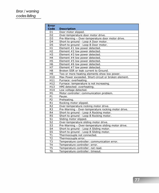
77
Error / warning
codes listing
Error Code Description
D1 Door motor slipped.
D2 Over-temperature door motor drive.
D3 Pre-Warning – Over-temperature door motor drive.
D4 Short to ground - Loop A Door motor.
D5 Short to ground - Loop B Door motor.
H1 Element #1 low power detected.
H2 Element #2 low power detected.
H3 Element #3 low power detected.
H4 Element #4 low power detected.
H5 Element #5 low power detected.
H6 Element #6 low power detected.
H7 Element #7 low power detected.
H8 Broken SSR or leak current to Ground.
H9 Two or more heating elements show low power.
H10 Max Power exceeded. Short-circuit or broken element.
H11 Furnace: overheating.
H12 Furnace: temperature is not increasing.
H13 HMI detected: overheating.
H14 Low voltage detected.
M1 Motor controller: communication problem.
P1 Pause.
P2 Preheating.
R1 Rocking motor slipped.
R2 Over-temperature rocking motor drive.
R3 Pre-Warning - Over-temperature rocking motor drive.
R4 Short to ground - Loop A Rocking motor.
R5 Short to ground - Loop B Rocking motor.
S1 Sliding motor slipped.
S2 Over-temperature sliding motor drive.
S3 Pre-Warning – Over-temperature sliding motor drive.
S4 Short to ground - Loop A Sliding motor.
S5 Short to ground - Loop B Sliding motor.
T1 Thermocouple not connected.
T2 Thermocouple error.
T3 Temperature controller: communication error.
T4 Temperature controller: error.
T5 Temperature controller: not read.
T6 Temperature controller: timeout.
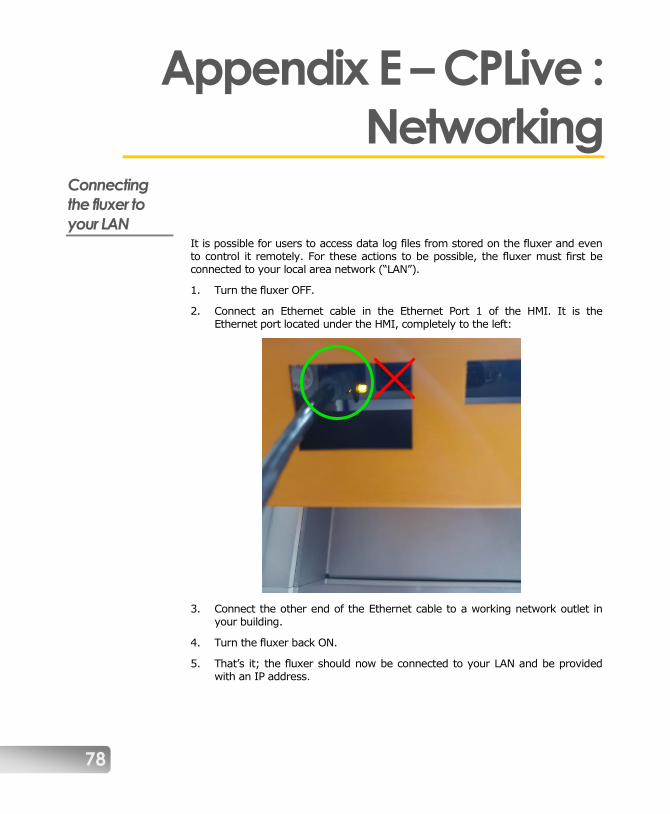
78
Appendix E – CPLive :
Networking Connecting
the fluxer to
your LAN It is possible for users to access data log files from stored on the fluxer and even to control it remotely. For these actions to be possible, the fluxer must first be connected to your local area network (“LAN”).
1. Turn the fluxer OFF.
2. Connect an Ethernet cable in the Ethernet Port 1 of the HMI. It is the Ethernet port located under the HMI, completely to the left:
3. Connect the other end of the Ethernet cable to a working network outlet in your building.
4. Turn the fluxer back ON.
5. That’s it; the fluxer should now be connected to your LAN and be provided with an IP address.

79
6. If you need to check the connectivity and obtain the IP address of your fluxer on the network:
a. Click the global parameters button:
b. Write down the IP address of your fluxer, e.g. 192.168.2.18 in the
example below:
c. If this field shows “0.0.0.0” there is a connectivity issue. Verify the cable and check your LAN wall socket for signal.

80
Appendix F – CPLive :
Remote access It is possible to remotely access the touchscreen of your new-generation fluxer remotely, through a computer, a tablet or a cellphone.
Additionally, with your explicit permission, it is possible for a Katanax technician to access it, thus allowing for remote diagnostics of your unit.
Controlling the
fluxer from a
remote device This allows the user to see a clone image of the fluxer’s touchscreen, and even interact with it. Any action that can be done on the fluxer’s touchscreen can also be done on the remote device.
NOTE : Both the fluxer and the controlling device must be connected to the same LAN.
1. Connect the fluxer to your local network and note your fluxer’s IP address. (Refer to Appendix E – CPLive : Networking on page 78 for details.)
2. In order to control the fluxer, you will need a program called a Virtual Networking Computing (“VNC”) viewer. Although several such applications exist on a multitude of devices and operating systems, the rest of this example will be based on using a Windows PC with the free VNC viewer from RealVNC:
https://www.realvnc.com/en/connect/download/viewer/
3. Download and install the VNC viewer on your computer.
4. Click “File > New Connection”. A new window will appear.
5. “General” tab
a. In the “VNC Server” field, type your fluxer’s IP address
b. In the “Name” field, type a connection name. We suggest you use the serial number of your instrument.
6. “Options” tab
a. If you wish to access the fluxer in view-only mode, you may tick the box to that effect.
7. Click “OK”. Your connection profile is now created.
81
8. Double-click on the connection profile you just created to initiate the actual connection process.
9. You may receive a warning that the connection with the fluxer will not be encrypted. Tick the box and click on “Continue”.
10. If the initial handshake is a success, you will be prompted for a password, which is six times the number one: “111111”
11. Tick the box if you want your device to remember your password, then click “OK” to connect.
12. You are now connected to your fluxer. You can interact with both the computer (remote) and the fluxer touchscreen (local).
13. To disconnect, close the VNC Viewer window.
14. To reconnect, start this procedure at step 8.
NOTE : If on a given day, the connection fails, it may be because a new IP was given to the fluxer by your network’s DCHP server. Check the IP address of the fluxer, and re-configure the VNC connection accordingly.
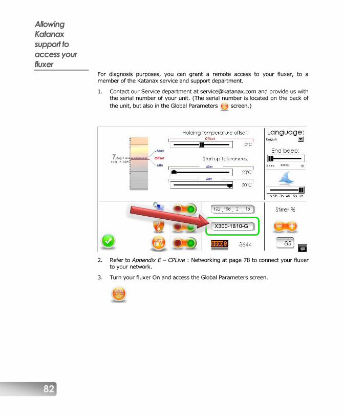
82
Allowing
Katanax
support to
access your
fluxer For diagnosis purposes, you can grant a remote access to your fluxer, to a member of the Katanax service and support department.
1. Contact our Service department at [email protected] and provide us with the serial number of your unit. (The serial number is located on the back of
the unit, but also in the Global Parameters screen.)
2. Refer to Appendix E – CPLive : Networking at page 78 to connect your fluxer to your network.
3. Turn your fluxer On and access the Global Parameters screen.
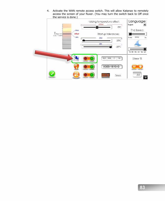
83
4. Activate the WAN remote access switch. This will allow Katanax to remotely access the screen of your fluxer. (You may turn the switch back to Off once the service is done.)

84
Contacting Katanax Katanax sales and technical staff can be reached at the following address:
Katanax inc.
2500, Jean-Perrin, suite 100
Quebec, QC
Canada G2C 1X1
Tel.: (+1) 418-915-4848
E-mail: [email protected]
Web: www.katanax.com
When contacting us, kindly have the serial number of the instrument at hand.
Customers are invited to visit our web site regularly, since useful information is periodically added.
An illustrated online parts browser is also available; kindly contact us to register.