Embed Size (px)
Citation preview

Automatic sliding doorsDCU1DCU1-2M
EN Wiring diagram
135680-03

Automatic sliding doors
2
Table of contents
Symbols and means of representation ........................................................................................................................4
Validity .....................................................................................................................................................................................4
Product liability.....................................................................................................................................................................4
1 Safety instructions ..................................................................................................................................................51.1 Important safety instructions .......................................................................................................................................................................51.2 Installation details ............................................................................................................................................................................................51.3 Safety-conscious working ..............................................................................................................................................................................51.4 Inspection of the installed system ..............................................................................................................................................................51.5 Disposal of the door system..........................................................................................................................................................................6
2 Abbreviations............................................................................................................................................................6
3 Safety sensor "close"...............................................................................................................................................83.1 Active infrared control light curtain and radar movement detector GC 363 R ..........................................................................83.2 Active infrared control light curtain and self-monitored radar movement detector GC 363 SF .........................................93.3 Active infrared control light curtain GC 339 ........................................................................................................................................ 103.4 Active infrared control light curtain and radar movement detector GC 362 R ....................................................................... 103.5 Active infrared control light curtain and self-monitored radar movement detector GC 362 SF ...................................... 113.6 Active infrared control light curtain GC 333 ........................................................................................................................................ 123.7 Active infrared sensor AIR 30 ..................................................................................................................................................................... 133.8 1-channel light barrier GZ 470 V .............................................................................................................................................................. 133.9 2-channel light barrier GZ 472 V .............................................................................................................................................................. 143.10 4-channel light barrier GZ 472 V .............................................................................................................................................................. 14
4 Safety sensor "open" ........................................................................................................................................... 154.1 Active infrared control light curtain GC 339 ........................................................................................................................................ 154.2 Active infrared control light curtain GC 333 ........................................................................................................................................ 164.3 Active infrared sensor AIR 30 ..................................................................................................................................................................... 16
5 Break-out doors .................................................................................................................................................... 175.1 Break-out sensor ............................................................................................................................................................................................ 175.2 Break-out sensor and safety sensor "open" .......................................................................................................................................... 175.3 Break-out sensor with active infrared control light curtain GC 339 ............................................................................................ 185.4 Break-out sensor with active infrared fan-shaped sensor GC 333 ............................................................................................... 185.5 Break-out sensor with active infrared fan-shaped sensor AIR 30 ................................................................................................. 19
6 Series connection of safety sensors ............................................................................................................... 206.1 Safety sensor "close" (standard doors) ................................................................................................................................................... 206.2 Safety sensor "close" (FR doors) ................................................................................................................................................................ 226.3 Protecting the sensor cable against short-circuit .............................................................................................................................. 24
7 Contact sensor authorised ................................................................................................................................ 257.1 Key push button ............................................................................................................................................................................................. 257.2 Emergency opening switch without illumination ............................................................................................................................. 257.3 Emergency opening switch with illumination .................................................................................................................................... 25
8 Contact sensor inside .......................................................................................................................................... 268.1 Standard doors ............................................................................................................................................................................................... 268.2 Doors on rescue routes ................................................................................................................................................................................ 27
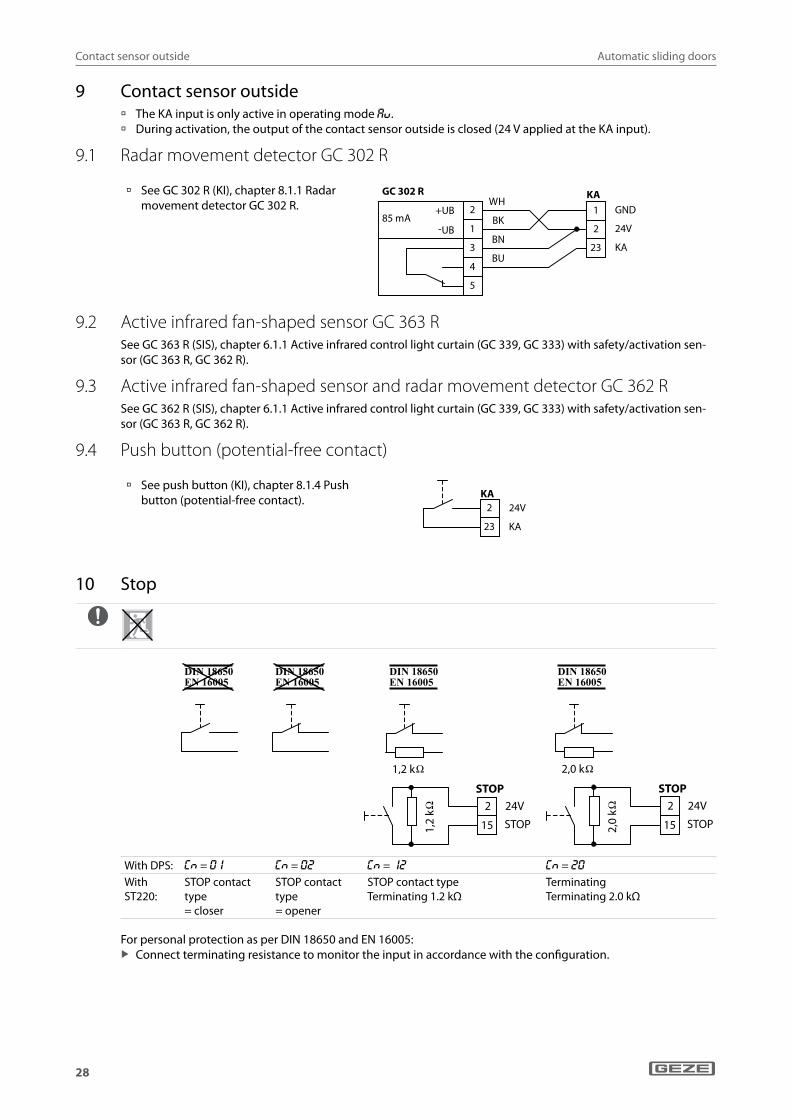
9 Contact sensor outside....................................................................................................................................... 289.1 Radar movement detector GC 302 R ...................................................................................................................................................... 289.2 Active infrared fan-shaped sensor GC 363 R ........................................................................................................................................ 289.3 Active infrared fan-shaped sensor and radar movement detector GC 362 R .......................................................................... 289.4 Push button (potential-free contact) ...................................................................................................................................................... 28

Automatic sliding doors
3
10 Stop ........................................................................................................................................................................... 28
11 Programmable inputs ......................................................................................................................................... 2911.1 Switch function ............................................................................................................................................................................................... 2911.2 Radio activation .............................................................................................................................................................................................. 2911.3 Pharmacy opening ........................................................................................................................................................................................ 3011.4 Emergency lock .............................................................................................................................................................................................. 30
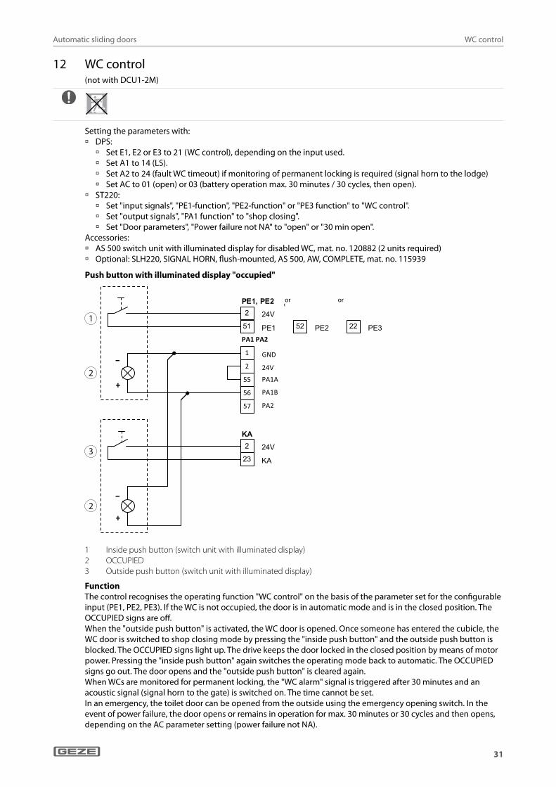
12 WC control .............................................................................................................................................................. 31
13 Interlocking door system, vestibule .............................................................................................................. 32
14 Mode of operation ............................................................................................................................................... 3314.1 Mechanical programme switch ................................................................................................................................................................ 3314.2 Switching the operating mode using push buttons or switches ................................................................................................. 3414.3 Keypad programme switch ........................................................................................................................................................................ 3414.4 Display programme switch (DPS) with OFF key ................................................................................................................................. 3514.5 Display programme switch (DPS) without OFF key .......................................................................................................................... 3514.6 Display programme switch, old version (mat. no. 103940) ............................................................................................................ 3614.7 Reset function (DPS with OFF key, TPS) ................................................................................................................................................. 3614.8 Blocking or releasing operation of TPS and DPS ................................................................................................................................ 36
15 Configurable outputs .......................................................................................................................................... 3715.1 PA1 (gong) ........................................................................................................................................................................................................ 3715.2 PA2 (fault, fan) ................................................................................................................................................................................................. 37
16 Mains connection ................................................................................................................................................. 38
17 Locking ..................................................................................................................................................................... 3917.1 Locking by toothed belt .............................................................................................................................................................................. 3917.2 Rod locking, break axle ................................................................................................................................................................................ 3917.3 Hook bolt Lock A ............................................................................................................................................................................................ 40
18 Rechargeable battery ......................................................................................................................................... 40
19 Motor ........................................................................................................................................................................ 41
20 Control ...................................................................................................................................................................... 42
21 Commissioning and service ............................................................................................................................. 4321.1 Production test ............................................................................................................................................................................................... 4321.2 Commissioning ............................................................................................................................................................................................... 4321.3 Service ................................................................................................................................................................................................................ 46
22 Service menu ......................................................................................................................................................... 4722.1 Service terminal ST220 ................................................................................................................................................................................ 4722.2 Display programme switch (DPS) ............................................................................................................................................................ 57
23 Fault messages ...................................................................................................................................................... 6423.1 Display programme switch ........................................................................................................................................................................ 6423.2 Keypad programme switch ........................................................................................................................................................................ 65

Automatic sliding doors
4
Symbols and means of representation
WarningsIn these instructions, warnings are used to warn against material damage and injuries.
X Always read and observe these warnings. X Observe all the measures that are marked with the warning symbol and warning word.
Warning symbol Warning word Meaning
DANGER Danger to persons. Non-compliance will result in death or serious injuries.
WARNING Danger to persons. Non-compliance can result in death or serious injuries.
CAUTION Danger to persons. Non-compliance can result in minor injuries.
Other symbols and means of representationImportant information and technical notes are highlighted to explain correct operation.
Symbol Meaning
means "important note"
means "additional information"
X Symbol for an action: Here you have to do something. X If there are several actions to be taken, keep to the given order.
Escape and rescue route Symbol in a table or for a piece of information only applicable to escape and rescue route doors.
Not an escape and rescue route Symbol in a table or relating to information which applies to standard doors without an escape and rescue route function.
Conforms to DIN 18650/EN 16005
Symbol in a table or relating to information on safety sensors that are standard-compliant.
Does not conform to DIN 18650 / EN 16005
Symbol in a table or relating to information on safety sensors that are not standard-compliant.
ValidityValid for units with Hardware: DCU1 Rev D, DCU1-2M Rev D;Software: DCU1 V3.3, DCU1-2M V3.3
Product liabilityIn accordance with the manufacturer's liability for their products as defined in the German "Produkthaftungsge-setz" (Product Liability Act), the information contained in this brochure (product information and proper use, misuse, product performance, product maintenance, obligations to provide information and instructions) is to be noted and followed. Failure to comply releases the manufacturer from his statutory liability.

Automatic sliding doors
5
Safety instructions
1 Safety instructions
1.1 Important safety instructionsIt is important to follow these instructions for the safety of persons.These instructions must be kept. à Only specialists authorised by GEZE are permitted to carry out installation, commissioning and maintenance
work. à Unauthorised modifications to the system exclude GEZE from liability for any resulting damages. à GEZE makes no guarantee for combinations with third-party products. Use only original GEZE parts for repair
and maintenance work as well. à The connection to the mains voltage must be carried out by a qualified electrician. Perform the power connec-
tion and equipment earth conductor test in accordance with VDE 0100 Part 610. à Use an on-site 10-A overload cut-out as the line-side disconnecting device. à Attach safety stickers to glass door leaves, mat. no. 081476. à In accordance with Machinery Directive 98/37/EC, a safety analysis is to be performed and the door system
identified in accordance with CE Identification Directive 93/68/EEC before the door system is commissioned. à Observe the latest versions of directives, standards and country-specific regulations, in particular:
à AutSchR "Guidelines on automatic sliding doors in escape and rescue routes" à EN 16005 "Power operated pedestrian doorsets – Safety in use – Requirements and test methods" à DIN 18650, Part 1 and Part 2 "Automatic door systems" à DIN VDE 100-600 "Installation of low-voltage systems - Part 6 Tests" à DIN EN 60335-2-103 "Safety of electrical devices for home use and similar purposes; special requirements
for drives, for gates, doors and windows" à Accident Prevention Regulations, in particular BGV A1 (VBG1) "General Regulations" and BGV A3 (VBG4)
"Electrical Installations and Resources"
1.2 Installation details à The drive is designed only for use in dry rooms. X Only use the cables prescribed in the cable plan provided. Lay shields in accordance with the wiring diagram. X Always use insulated wire-end ferrules for wire cores. X Insulate the wires that are not used. X Secure loose, internal drive cables with cable ties. X Observe the maximum permitted overall current drain required to supply the periphery.
1.3 Safety-conscious working X Secure the workplace against unauthorised entry. X Watch the swivelling range of long system parts. X Secure the hood/drive shrouding against falling. X Before carrying out work on the electrical system, cut the power supply (mains and battery) and check to
ensure that there is no power. When using an uninterrupted power supply (UPS), the system will still be under power even when disconnected from the mains.
à Risk of injury by moving parts (drawing in of hair, clothing, ...) when a drive is opened. à Risk of injury caused by unsecured crushing, impact, drawing-in or shearing spots. à Risk of injury caused by sharp edges in the drive. à Risk of injury due to glass breakage.
1.4 Inspection of the installed system X Measures for checking safety and prevention of crushing, impact, shearing or drawing-in spots. X Check the function of the presence sensors and movement detectors.
à The detection field of the movement detector in the direction of emergency exit must cover the opening width (ÖW) × 1.5 m in front of the door.
X Check the protective earth connection to all metal parts that can be touched.
Automatic sliding doors
6
Abbreviations
1.5 Disposal of the door system à The door system is made up of materials that should be sent for recycling.
For this purpose, the individual components should be sorted corresponding to material type: à Aluminium (profiles, covering, return pulleys, sliding blocks, ...) à Iron (drivers, screws, ...) à Plastic à Electronic parts (bolts, motor, control, transformer, sensors, ...) à Cable à Rechargeable battery
X The parts listed should be handed in to communal collection points or be disposed of via a scrap recycling company.
à Rechargeable batteries and batteries contain pollutants and heavy metals. X Rechargeable batteries and waste batteries should be handed in to communal collection points or retailers.
à The rechargeable battery for the drive is a plug-in type and connected to the control; it can be removed easily by loosening two fixing screws.
Information regarding the Battery Directive:(Applicable in Germany and in all other member states of the European Union as well as in other European coun-tries, together with the countries' own provisions for a separate waste battery collection system.) In accordance with the Battery Directive, we are obliged to inform you of the following in connection with the sale of batteries or rechargeable batteries respectively in connection with the delivery of devices containing bat-teries or rechargeable batteries: Rechargeable batteries and batteries must not be disposed of with household waste. Disposal with household waste is expressly forbidden according to the Battery Directive. As the final con-sumer, you are bound by law to return waste batteries and rechargeable batteries. Please return waste batteries and rechargeable batteries to a communal collection point or retailer. Following use, you may return any batteries or rechargeable batteries received from us by post. The address is: GEZE GmbH, Incoming Goods, Reinhold-Vöster-Str. 21-29, 71229 Leonberg/Germany.
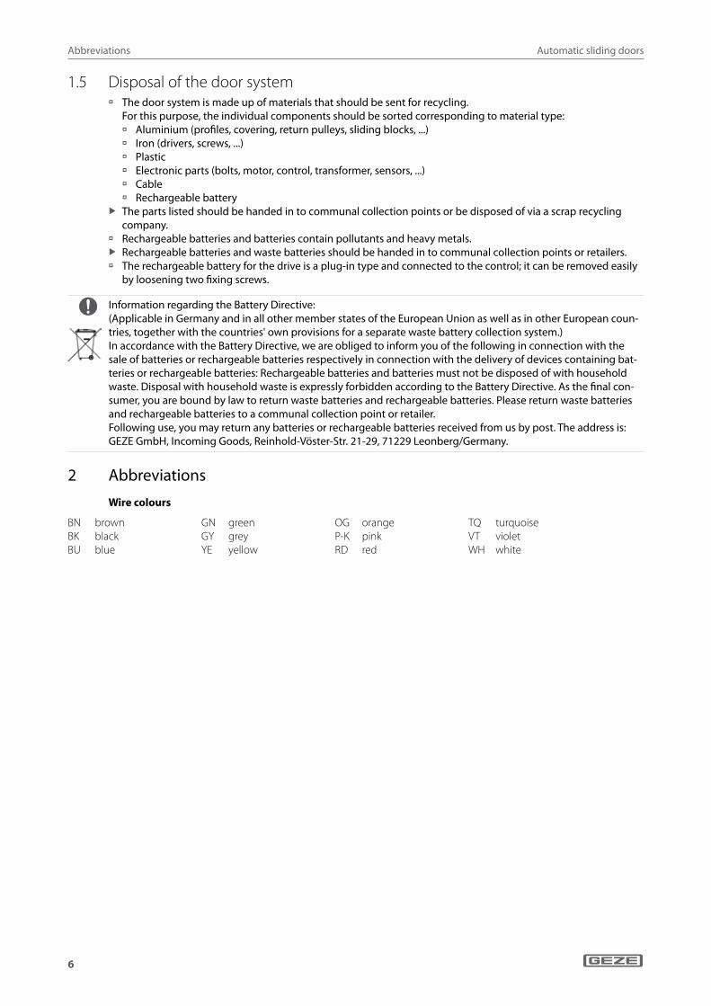
2 Abbreviations
Wire colours
BN brownBK blackBU blue
GN greenGY greyYE yellow
OG orangeP-K pinkRD red
TQ turquoiseVT violetWH white
Automatic sliding doors
7
Abbreviations
Connections, terminals and plugs
AIR Active infrared control light curtain
APO Pharmacy openingAU AutomaticDO Permanently openDPS Display programme
switch ENC Incremental en-
coderGND Reference potentialIR InfraredKA Contact sensor
outsideKB Contact sensor
authorisedKI Contact sensor
insideLK Luster terminalLCK_A Locking, ALCK_B Locking, BLKD LockedLS Shop closingM1A Motor 1, AM2A Motor 2, A
M1B Motor 1, BM2B Motor 2, BMPS Mechanical programme
switch NA NightN.C. Not usedNC Opening contact
(normally closed)NO Closer contact
(normally open)NOTVER Emergency lockOFF OffÖW Opening widthPA Output programmablePE Input programmablePROG Programming interfacePS Programme switchRBM Radar movement detectorRUN Status displayRS485 Communication signal
to DPS, TPS
SABO SabotageSCR ShieldSHLD Shield SIO Safety sensor "open"SIS Safety sensor "close"ST220 Service terminal ST220
(mat. no. 087261)STG FaultSYNC SynchronisationTEMP Temperature sensorTest Test inputTPS Keypad programme
switchTST Test signal safety sensorsULKD Unlocked+UB Supply voltage +–UB Supply voltage –24V Supply voltage for
external devices, max. 1.0 A
24VAKKU Supply during mains power failure, max. 20 mA
PE1 PE2 PA1 PA2
STOP PS SIS2 SIO2
PE3 SIO1 SIS1
KI KA RS485KB
DCU103
RUN
PRO
G
LOCK
GND1
2 24V
51 PE1
52 PE2
PE1 PE 2
PA1A
PA1B
GND1
2 24V
55
56
PA1 PA2
PA257
SIS212
1 GND
2 24V
10 TST
SIS2SIO214
1 GND
2 24V
10 TST
SIO2
24V2
15 STOP
STOP
GND1
2 24V
21 KI (Kl1)
KI
GND1
2 24V
23 KA
KA
24V2
6 NA
7 LS
8 AUT
PS
DO9
3 24VAKKU
20 KB
KB
GND1
2 24V
22 PE3 (Kl2)
PE3
SIO113
1 GND
2 24V
10 TST
SIO1
GND1
2 24V
11 SIS1
1 GND
2 24V
10 TST
SIS1
Automatic sliding doors
8
Safety sensor "close"
3 Safety sensor "close" à Up to four safety sensors "close" can be connected (terminals SIS1, SIS2, SIO1 and SIO2). à During detection, the output of the safety sensor "close" is open. GND is applied to the input. à Set the contact type for the terminal used:
à With DPS: s1, s2, s3 or s4 to o2 à With ST220: "SI1-", "SI2-", "SI3-" or "SI4-contact type" to "opener"
à Set the function for detection (see Service menu chapter): à With DPS: f1, f2, f3 or f4 à With ST220: "SI1-", "SI2-", "SI3-" or "SI4-function"
à Check function and correct setting of the sensors during commissioning and service.
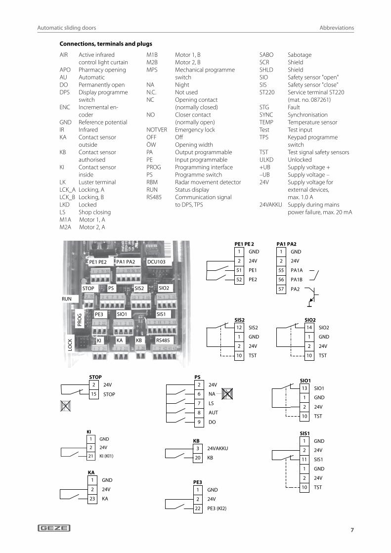
3.1 Active infrared control light curtain and radar movement detector GC 363 R
Installation height max. 3500 mm
à GC 363 R black, mat. no. 151237 à GC 363 R according to RAL, mat. no. 151238 à The GC 363 R contains an active infrared con-
trol light curtain and a direction-sensitive radar movement detector.
GND1
2 24V
11 SIS1
1 GND
2 24V
10 TST
SIS1 1 GND
2 24V
1 GND
2 24V
10 TST
12 SIS2
oder
2 24V
21 KI
KI2 24V
23 KA
KA
110 mA
RBM
GC 363 R
-UB
+UB
COM
+
BN
GN
GY
PK
BU
RD
WH
YE
SIS2
1
2
1 AIR curtain2 Test
à In order to safeguard the closing process in compliance with EN 16005 and DIN 18650, a light curtain must be installed on both the inside and outside. The detection field of the light curtain on the floor must cover the whole door width.
X Follow installation instructions GC 363 R / SF.
Necessary parameter adjustment GC 363 R
à Output configuration: WHEEL: OUTPUT to 1 (NO)
AIR: OUTPUT to 1 (NC)
Necessary setting on the control à Set parameter Ci (contact sensor inside, contact type) or Co (contact sensor outside, contact type) to 01
(closer).
or
Automatic sliding doors
9
Safety sensor "close"
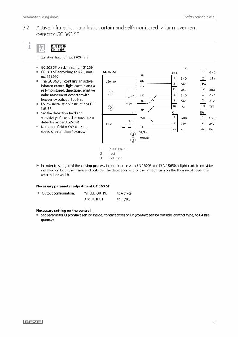
3.2 Active infrared control light curtain and self-monitored radar movement detector GC 363 SF
Installation height max. 3500 mm
à GC 363 SF black, mat. no. 151239 à GC 363 SF according to RAL, mat.
no. 151240 à The GC 363 SF contains an active
infrared control light curtain and a self-monitored, direction-sensitive radar movement detector with frequency output (100 Hz).
X Follow installation instructions GC 363 SF.
X Set the detection field and sensitivity of the radar movement detector as per AutSchR:
à Detection field = ÖW × 1.5 m, speed greater than 10 cm/s.
1
2
33
2 24V
21 KI
KI
COM
+
BN
GN
GY
PK
BU
RD
WH
YE RBM
WH/BK
120 mA
GC 363 SF
YE/BK
1 GND
+UB
1 GND
SIS2
1 GND
2 24V
10 TST
12 SIS2
oder
GND 1
2 24V
11 SIS1
1 GND
2 24V
10 TST
SIS1
2 24V
23 KA
KA
1 GND
2 24 V
1 AIR curtain2 Test3 not used
X In order to safeguard the closing process in compliance with EN 16005 and DIN 18650, a light curtain must be installed on both the inside and outside. The detection field of the light curtain on the floor must cover the whole door width.
Necessary parameter adjustment GC 363 SF
à Output configuration: WHEEL: OUTPUT to 6 (freq)
AIR: OUTPUT to 1 (NC)
Necessary setting on the control à Set parameter Ci (contact sensor inside, contact type) or Co (contact sensor outside, contact type) to 04 (fre-
quency).
or
Automatic sliding doors
10
Safety sensor "close"
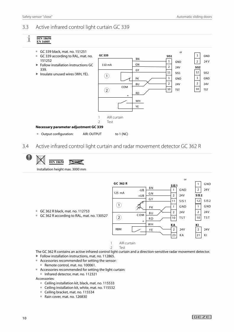
3.3 Active infrared control light curtain GC 339
à GC 339 black, mat. no. 151251 à GC 339 according to RAL, mat. no.
151252 X Follow installation instructions GC
339. X Insulate unused wires (WH, YE). 1
2
COM
+
BN
GN
GY
PK
BU
RD
WH
YE
110 mA
GC 339 1 GND
SIS2
1 GND
2 24V
10 TST
12 SIS2
oder
GND 1
2 24V
11 SIS1
1 GND
2 24V
10 TST
SIS1
2 24 V
1 AIR curtain2 Test
Necessary parameter adjustment GC 339
à Output configuration: AIR: OUTPUT to 1 (NC)
3.4 Active infrared control light curtain and radar movement detector GC 362 R
Installation height max. 3000 mm
à GC 362 R black, mat. no. 112753 à GC 362 R according to RAL, mat. no. 130527
-UB
+UB
C OM
+
125 mA
GC 362 R B N
G N
G Y
P K
B U
R D
W H
Y E
G ND1
2 24V
11 S IS 1
1 G ND
2 24V
10 T S T
S IS 1 1 G ND
2 24V
S IS 2
1 G ND
2 24V
10 T S T
12 S IS 2
2 24V
23 K A
K A2 24V
21 K I
K I
oder
RBM
1
2
1 AIR curtain2 Test
The GC 362 R contains an active infrared control light curtain and a direction-sensitive radar movement detector. X Follow installation instructions, mat. no. 112865.
à Accessories recommended for setting the sensor: à Remote control, mat. no. 100061.
à Accessories recommended for setting the light curtain: à Infrared detector, mat. no. 112321
Accessories: à Ceiling installation kit, black, mat. no. 115533 à Ceiling installation kit, white, mat. no. 115532 à Ceiling bracket, mat. no. 115534 à Rain cover, mat. no. 126830
or
or

Automatic sliding doors
11
Safety sensor "close"
à To safeguard the closing movement, a light curtain with a detection field covering the entire door width on the floor and monitoring the area up to a height of at least 2,000 mm above the ground (where the main closing edge meets the opposite closing edge) must be mounted both inside and outside as per DIN 18650.
à The distance between the detection fields must not exceed 200 mm. à If only one light curtain is used, the detection field must be located on the floor as close to the door leaf as pos-
sible. X Set the tilt angle of the optic block accordingly for this purpose.
à Half- or fully-grooved prism: wide/narrow detection field of the IR curtain à 3-piece/6-piece aerial insert: wide/narrow detection field of the radar movement detector
Necessary parameter adjustment GC 362 R
à Output configuration: 1 (radar output active, IR output passive)
à Presence detection duration:
1 to 6 (1 to 60 minutes); the value 0 (30 sec.) is not permitted.
à Monitoring mode: 1 (on)
à Multi mode: If adjacent light curtains overlap, set different infrared frequencies.
Necessary setting on the control X Set Ci (contact sensor inside, contact type) or Co (contact sensor outside, contact type) to 01 (closer).
3.5 Active infrared control light curtain and self-monitored radar movement detector GC 362 SF
Installation height max. 3000 mm
à GC 362 SF black, mat. no. 127091 à GC 362 SF according to RAL, mat. no. 130526
G ND1
2 24V
11 S IS 1
1 G ND
2 24V
10 T S T
S IS 1 1 G ND
2 24V
S IS 2
1 G ND
2 24V
10 T S T
12 S IS 2
2 24V
21 K I
K I
-UB
+UB
C OM
+
125 mA
B N
G N
G Y
P K
B U
R D
Y E
W H
GC 362 S F oder
RBM
1
2
1 AIR curtain2 Test
à The GC 362 SF contains an active infrared control light curtain and a self-monitored, direction-sensitive radar movement detector with frequency output (100 Hz).
X Follow installation instructions, mat. no. 112869. à The GC 362 SF is used in the direction of emergency exit. X Set the detection field and sensitivity of the radar movement detector as per AutSchR:
à Detection field = ÖW × 1.5 m, speed greater than 10 cm/s.
Necessary setting on the control X Set Ci (contact sensor inside, contact type) or Co (contact sensor outside, contact type) to 04 (frequency).
or

Automatic sliding doors
12
Safety sensor "close"
Necessary parameter adjustment GC 362 SF
à Output configuration: 1 (IR output passive)
à Presence detection duration:
1 to 6 (1 minute to 60 minutes), the value 0 (30 s) is not permitted.
à Monitoring mode: 1 (on)
à Multi mode: If adjacent light curtains overlap, set different infrared frequencies.
à The connection of two radar movement detectors of type GC 362 SF in the direction of emergency exit is not possible.
X Instead, use sensor GC 363 SF incl. GC 363 S interface (see chapter 6.2.2).
3.6 Active infrared control light curtain GC 333
Installation height up to 3000 mm
à GC 333 black, mat. no. 112755 à GC 333 according to RAL, mat. no. 130528
G ND 1
2 24V
11 S IS 1
1 G ND
2 24V
10 T S T
S IS 1 1 G ND
2 24V
S IS 2
1 G ND
2 24V
10 T S T
12 S IS 2
B N
G N
G Y
P K
B U
R D
W H*
Y E*
125 mA
GC 333
-UB
+UB
C OM
oder
1
2
1 AIR curtain2 Test* Insulate unused wires (WH, YE)
The GC 333 contains an active infrared control light curtain. X Follow installation instructions, mat. no. 112873.
à For further information see GC 362 R (SIS).Accessories: à Ceiling installation kit, black, mat. no. 115533 à Ceiling installation kit, white, mat. no. 115532 à Ceiling bracket, mat. no. 115534 à Rain cover, mat. no. 126830 à Accessories recommended for setting the sensor:
à Remote control, mat. no. 100061 à Accessories recommended for setting the light curtain:
à Infrared detector, mat. no. 112321
Necessary parameter adjustment GC 333
Monitoring mode: 1 (on)
or
Automatic sliding doors
13
Safety sensor "close"
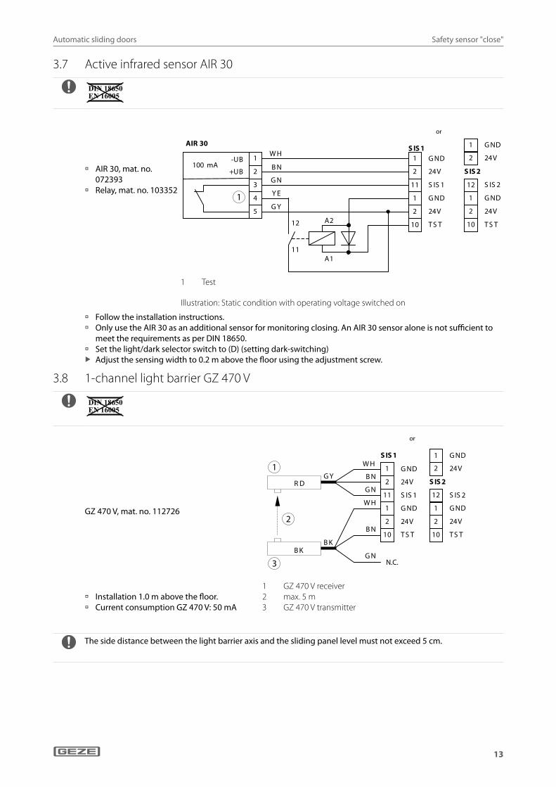
3.7 Active infrared sensor AIR 30
à AIR 30, mat. no. 072393
à Relay, mat. no. 103352
12
11
A2
A1
G ND1
2 24V
11 S IS 1
1 G ND
2 24V
10 T S T
S IS 1 1 G ND
2 24V
S IS 2
1 G ND
2 24V
10 T S T
12 S IS 2
100 mA -UB
+UB
1
2
3
4
5
W H
B N
G N
Y E
G Y
AIR 30 oder
1
1 Test
Illustration: Static condition with operating voltage switched on
à Follow the installation instructions. à Only use the AIR 30 as an additional sensor for monitoring closing. An AIR 30 sensor alone is not sufficient to
meet the requirements as per DIN 18650. à Set the light/dark selector switch to (D) (setting dark-switching) X Adjust the sensing width to 0.2 m above the floor using the adjustment screw.
3.8 1-channel light barrier GZ 470 V
GZ 470 V, mat. no. 112726
à Installation 1.0 m above the floor. à Current consumption GZ 470 V: 50 mA
S ender G Z470 V
G Z470 V E mpfänge r
G Y
B K
R D
B K
B N
G N
W H
B N
G N
1
2 24V
11 S IS 1
1 G ND
2 24V
10 T S T
S IS 1
G ND
1 G ND
2 24V
1 G ND
2 24V
10 T S T
S IS 2
12 S IS 2
oder
W H
nicht belegt N.C.
1
3
2
1 GZ 470 V receiver2 max. 5 m3 GZ 470 V transmitter
The side distance between the light barrier axis and the sliding panel level must not exceed 5 cm.
or
or

Automatic sliding doors
14
Safety sensor "close"
3.9 2-channel light barrier GZ 472 V
GZ 472 V, mat. no. 112727
1 GZ 472 ES V transmitter2 GZ 472 ES V receiver3 max. 5 m4 GZ 472 SE V transmitter5 GZ 472 SE V receiver
W H
B K
G ND1
2 24V
11 S IS 1
1 G ND
2 24V
10 T S T
S IS 1
G Y B N
G N
W H
B N
G N
B KB K
R DG Y
R D
B K
1 G ND
2 24V
1 G ND
2 24V
10 T S T
S IS 2
12 S IS 2
oder
1
3
4 5
2
à Installation 0.2 m and 1.0 m above the floor respectively. à Current consumption GZ 472 V: 70 mA
The side distance between the light barrier axis and the sliding panel level must not exceed 5 cm.
3.10 4-channel light barrier GZ 472 V
According to DIN 18650 safeguarding with light barriers is not suitable for people in need of special protection.
X Note and follow other standard-related requirements such as power limitation etc.
GZ 472 V, mat. no. 112727
à Install one channel 0.2 m above the ground, another one 1.0 m above the ground and the other channels as required.
X Install GZ 472 SE V on the left, GZ 472 ES V on the right in each case.
à Current consumption GZ 472 V: 70 mA
1 GZ 472 ES V transmitter2 GZ 472 ES V receiver3 max. 5 m4 GZ 472 SE V transmitter5 GZ 472 SE V receiver
WH
BK
GND1
2 24V
11 SIS1
1 GND
2 24V
10 TST
SIS1
GY BN
GN
WH
BN
GN
BK
GZ472ES VSender
BK
Empfänger GZ472SE V
RDGY
Sender
Empfänger
RD
BK
1 2
4 5
3
WH
BK
BK
GZ472ES VSender
BK
Empfänger GZ472SE V
RDGY
1 GND
2 24V
SIS2
1 GND
2 24V
10 TST
12 SIS2
GY BN
GN
WH
BN
GN
Sender
Empfänger
RD
BK
1 2
4 5
3
The side distance between the light barrier axis and the sliding panel level must not exceed 5 cm.
or
Automatic sliding doors
15
Safety sensor "open"
4 Safety sensor "open"Check function and correct setting of the sensors during commissioning and service.
à Up to four safety sensors "open" can be connected (terminals SIO1, SIO2, SIS1 and SIS2). à During detection, the output of the safety sensor "open" is open. GND is applied to input SIO1 or SIO2. X Set contact type for terminals used:
à With DPS: Set s3, s4 , s1 or s2 to o2. à ST220: Set parameter "SI3", "SI4", "SI1" or "SI2 contact type" to "open"
X Set function for terminals used (see Chapter 23): à Set DPS parameter f3, f4, f1 or f2. à Set ST220 parameter "SI3-", "SI4-", 2SI1-" or "SI2-function".
For doors in rescue routes: If the safety sensor "open" is activated during opening, the door does not stop until the reduced opening width is reached. The reduced opening width must be larger than or the same size as the required escape route width (official building approval).
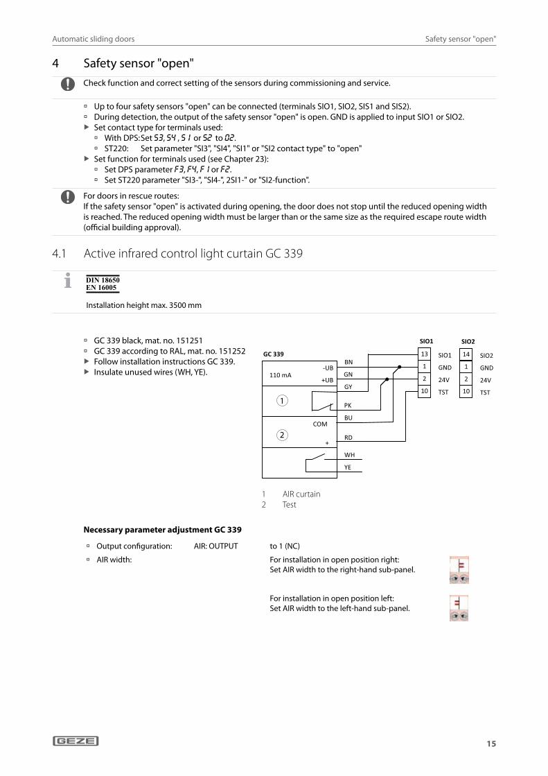
4.1 Active infrared control light curtain GC 339
Installation height max. 3500 mm
à GC 339 black, mat. no. 151251 à GC 339 according to RAL, mat. no. 151252 X Follow installation instructions GC 339. X Insulate unused wires (WH, YE).
1
2
SIO1
1 GND
2 24V
10 TST
13 SIO1
SIO2
1 GND
2 24V
10 TST
14 SIO2
-UB
+UB
COM
+
BN
GN
GY
PK
BU
RD
WH
YE
110 mA
GC 339
1 AIR curtain2 Test
Necessary parameter adjustment GC 339
à Output configuration: AIR: OUTPUT to 1 (NC)
à AIR width: For installation in open position right:Set AIR width to the right-hand sub-panel.
For installation in open position left: Set AIR width to the left-hand sub-panel.
Automatic sliding doors
16
Safety sensor "open"
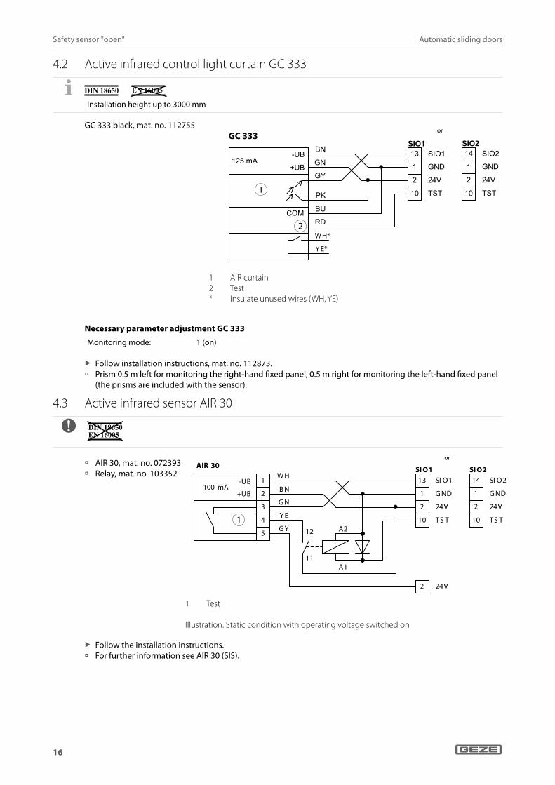
4.2 Active infrared control light curtain GC 333
Installation height up to 3000 mm
GC 333 black, mat. no. 112755
1
2W H*
Y E*
GC 333
1 AIR curtain2 Test* Insulate unused wires (WH, YE)
Necessary parameter adjustment GC 333
Monitoring mode: 1 (on)
X Follow installation instructions, mat. no. 112873. à Prism 0.5 m left for monitoring the right-hand fixed panel, 0.5 m right for monitoring the left-hand fixed panel
(the prisms are included with the sensor).
4.3 Active infrared sensor AIR 30
à AIR 30, mat. no. 072393 à Relay, mat. no. 103352
100 mA -UB
+UB
1
2
3
4
5
W H
B N
G N
Y E
G Y
AIR 30
13 SI O1
1 G ND
2 24V
10 T S T
SI O1 SI O2
1 G ND
2 24V
10 T S T
14 SI O2
2 24V
12
11
A2
A1
oder
1
1 Test
Illustration: Static condition with operating voltage switched on
X Follow the installation instructions. à For further information see AIR 30 (SIS).
or
or
Automatic sliding doors
17
Break-out doors
5 Break-out doors X Before commissioning, set the drive type in the Service menu "Door parameters" "Drive type" (Slimdrive SL BO,
ECdrive BO or TSA 360NT BO). X Note the contents of the "Guidelines on automatic sliding doors in escape and rescue routes (AutSchR)":
à The programme switch must be protected from unauthorised access e.g. by installing a key push button to block the programme switch.
à The functions emergency lock, interlocking door system and vestibule are not permitted with automatic sliding doors on rescue routes.
à The operating mode setting "Night" with timer or switch is not possible. à The function "pharmacy" is not available as an input parameter.
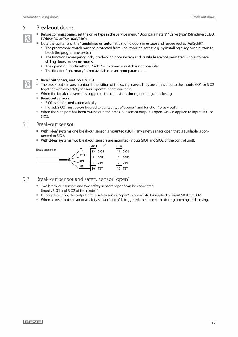
à Break-out sensor, mat. no. 076114 à The break-out sensors monitor the position of the swing leaves. They are connected to the inputs SIO1 or SIO2
together with any safety sensors "open" that are available. à When the break-out sensor is triggered, the door stops during opening and closing. à Break-out sensors
à SIO1 is configured automatically. à If used, SIO2 must be configured to contact type "opener" and function "break-out".
à When the side part has been swung out, the break-out sensor output is open. GND is applied to input SIO1 or SIO2.
5.1 Break-out sensor à With 1-leaf systems one break-out sensor is mounted (SIO1), any safety sensor open that is available is con-
nected to SIO2. à With 2-leaf systems two break-out sensors are mounted (inputs SIO1 and SIO2 of the control unit).
Break-OutSensor
SIO1 SIO2YE
WH
GN
BN
13
1
10
2
14
1
10
2
SIO1
oder
GND
TST
24V
SIO2
GND
TST
24V
5.2 Break-out sensor and safety sensor "open" à Two break-out sensors and two safety sensors "open" can be connected
(inputs SIO1 and SIO2 of the control). à During detection, the output of the safety sensor "open" is open. GND is applied to input SIO1 or SIO2. à When a break-out sensor or a safety sensor "open" is triggered, the door stops during opening and closing.
or
Break-out sensor
Automatic sliding doors
18
Break-out doors
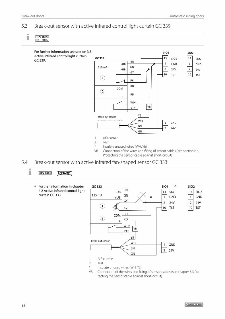
5.3 Break-out sensor with active infrared control light curtain GC 339
For further information see section 3.3 Active infrared control light curtain GC 339.
1
2
SIO1
1 GND
2 24V
10 TST
13 SIO1
SIO2
1 GND
2 24V
10 TST
14 SIO2
Break-Out Sensor
BN
GN
WH
YE
1 GND
2 24V
VB
-UB
+UB
COM
+
BN
GN
GY
PK
BU
RD
110 mA
GC 339
W H*
Y E*
1 AIR curtain2 Test* Insulate unused wires (WH, YE)VB Connection of the wires and fixing of sensor cables (see section 6.3
Protecting the sensor cable against short-circuit)
5.4 Break-out sensor with active infrared fan-shaped sensor GC 333
à Further information in chapter 4.2 Active infrared control light curtain GC 333
GC 333
Break-Out Sensor
125 mA
BN
GN
GY
PK
BU
RD
YE
WH
BN
GN
COM
+
-UB
+UB
SIO1 oder SIO2
131
210
SIO1GND
24V
GND
24V
TST
SIO2GND
24VTST
141
210
1
2
1
2
VB W H*
Y E*
1 AIR curtain2 Test* Insulate unused wires (WH, YE)VB Connection of the wires and fixing of sensor cables (see chapter 6.3 Pro-
tecting the sensor cable against short-circuit)
or
Break-out sensor
Break-out sensor
Automatic sliding doors
19
Break-out doors
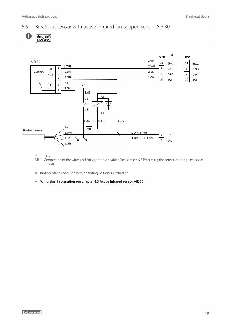
5.5 Break-out sensor with active infrared fan-shaped sensor AIR 30
oder
1
Break-Out Sensor
1.BN
1.GN
1.WH
1.YE
100 mA -UB
+UB
1
2
3
4
5
2.WH
2.BN
2.GN
2.YE
2.GY VB
3.YE
3.GN
12
11
A2
A1
3.BN
VB
SIO1
1 GND
2 24V
10 TST
13 SIO1
SIO2
1 GND
2 24V
10 TST
14 SIO2
1 GND
2 24V
3.WH
1.GN
1.WH, 3.WH
1.BN, 2.GY, 3.GN
2.BN
2.WH
2.GN AIR 30
1 TestVB Connection of the wires and fixing of sensor cables (see section 6.3 Protecting the sensor cable against short-
circuit)
Illustration: Static condition with operating voltage switched on
à For further information see chapter 4.3 Active infrared sensor AIR 30
or
Break-out sensor
Automatic sliding doors
20
Series connection of safety sensors
6 Series connection of safety sensors
6.1 Safety sensor "close" (standard doors)
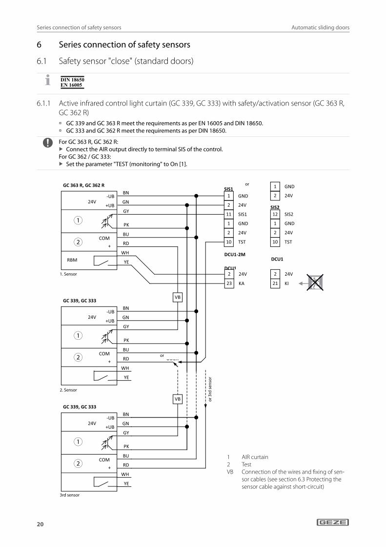
6.1.1 Active infrared control light curtain (GC 339, GC 333) with safety/activation sensor (GC 363 R, GC 362 R) à GC 339 and GC 363 R meet the requirements as per EN 16005 and DIN 18650. à GC 333 and GC 362 R meet the requirements as per DIN 18650.
For GC 363 R, GC 362 R: X Connect the AIR output directly to terminal SIS of the control.
For GC 362 / GC 333: X Set the parameter "TEST (monitoring" to On [1].
1
2
1
2
1
2
GND 1
2 24V
11 SIS1
1 GND
2 24V
10 TST
SIS1 1 GND
2 24V
SIS2
1 GND
2 24V
10 TST
12 SIS2
oder
2 24V
23 KA
DCU1-2M
DCU12 24V
21 KI
DCU1
VB
VB
ODER
Ode
r 3
. Sen
sor
BN
GN
GY
PK
BU
RD
WH
YE
24V
GC 339, GC 333
-UB
+UB
COM
+
BN
GN
GY
PK
BU
RD
WH
YE
24V
GC 363 R, GC 362 R
-UB
+UB
COM
+
RBM
1.Sensor
2.Sensor
3.Sensor
BN
GN
GY
PK
BU
RD
WH
YE
24V
GC 339, GC 333
-UB
+UB
COM
+
1 AIR curtain2 TestVB Connection of the wires and fixing of sen-
sor cables (see section 6.3 Protecting the sensor cable against short-circuit)
or
or
1. Sensor
2. Sensor
3rd sensor
or 3
rd s
enso
r
Automatic sliding doors
21
Series connection of safety sensors
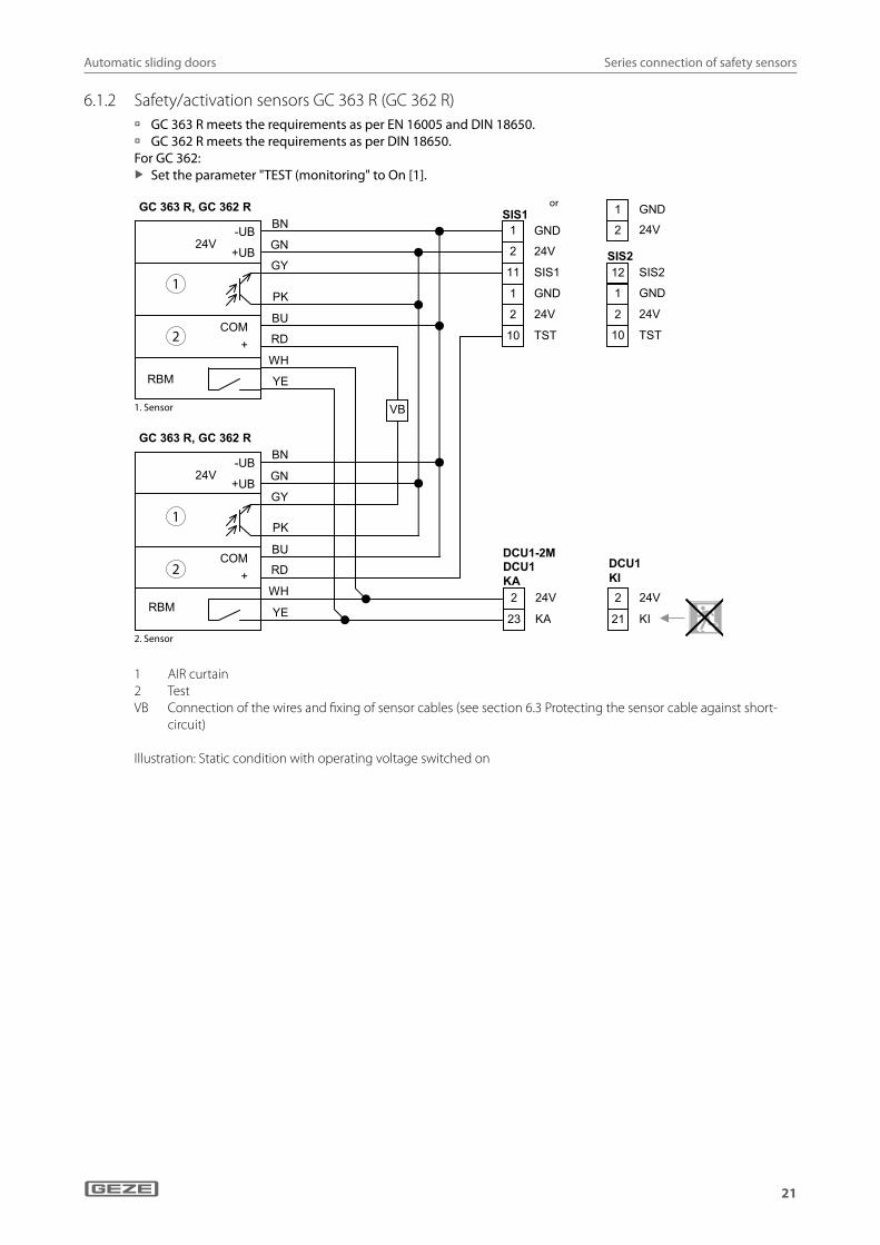
6.1.2 Safety/activation sensors GC 363 R (GC 362 R) à GC 363 R meets the requirements as per EN 16005 and DIN 18650. à GC 362 R meets the requirements as per DIN 18650.
For GC 362: X Set the parameter "TEST (monitoring" to On [1].
GND1
2 24V
11 SIS1
1 GND
2 24V
10 TST
SIS1 1 GND
2 24V
SIS2
1 GND
2 24V
10 TST
12 SIS2
oder
2 24V
23 KA
DCU1-2MDCU1 KA
2 24V
21 KI
DCU1KI
VB
BN
GN
GY
PK
BU
RD
WH
YE
24V
GC 363 R, GC 362 R
-UB
+UB
COM+
RBM
RBM
BN
GN
GY
PK
BU
RD
WH
YE
24V
GC 363 R, GC 362 R
-UB
+UB
COM+
1
2
1
2
1. Sensor
2. Sensor
1 AIR curtain2 TestVB Connection of the wires and fixing of sensor cables (see section 6.3 Protecting the sensor cable against short-
circuit)
Illustration: Static condition with operating voltage switched on
or
1. Sensor
2. Sensor

Automatic sliding doors
22
Series connection of safety sensors
6.2 Safety sensor "close" (FR doors)
6.2.1 Active infrared control light curtain (GC 339, GC 333) with safety/activation sensor (GC 363 SF, GC 362 SF) à GC 339 and GC 363 SF meet the requirements as per EN 16005 and DIN 18650. à GC 333 and GC 362 SF meet the requirements as per DIN 18650.
For GC 363 R, GC 362 R: X Connect the AIR output directly to terminal SIS of the control.
For GC 362 / GC 333: X Set the parameter "TEST (monitoring" to On [1].
1
2
1
2
1
2
33
GND 1
2 24V
11 SIS1
1 GND
2 24V
10 TST
SIS1 1 GND
2 24V
SIS2
1 GND
2 24V
10 TST
12 SIS2
oder
2 24V
21 KI
2 24V
23 KA
DCU1KA
DCU1-2MDCU1KA
VB
VB
ODER
Ode
r 3
. Sen
sor
BN
GN
GY
PK
BU
RD
WH
YE
24V
GC 339, GC 333
-UB
+UB
COM
+
1.Sensor
2.Sensor
3.Sensor
BN
GN
GY
PK
BU
RD
WH
YE
24V
GC 339, GC 333
-UB
+UB
COM
+
COM
+
BN
GN
GY
PK
BU
RD
WH
YE RBM
WH/BK
120 mA
GC 363 SF
YE/BK
+UB
1 AIR curtain2 Test3 not usedVB Connection of the wires and fixing of sensor ca-
bles (see chapter 6.3 Protecting the sensor cable against short-circuit)
or
or
1. Sensor
2. Sensor
3. Sensor
or 3
rd s
enso
r
Automatic sliding doors
23
Series connection of safety sensors
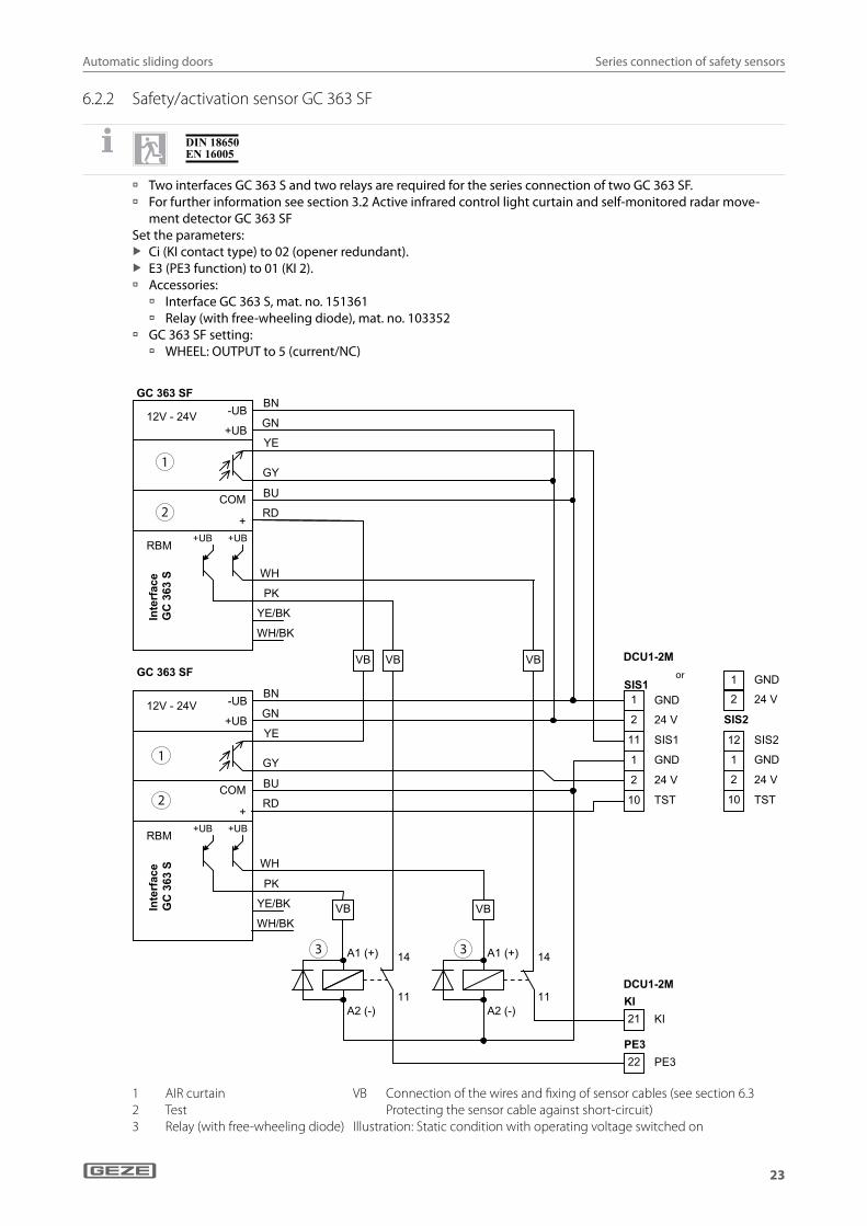
6.2.2 Safety/activation sensor GC 363 SF
à Two interfaces GC 363 S and two relays are required for the series connection of two GC 363 SF. à For further information see section 3.2 Active infrared control light curtain and self-monitored radar move-
ment detector GC 363 SFSet the parameters:
X Ci (KI contact type) to 02 (opener redundant). X E3 (PE3 function) to 01 (KI 2).
à Accessories: à Interface GC 363 S, mat. no. 151361 à Relay (with free-wheeling diode), mat. no. 103352
à GC 363 SF setting: à WHEEL: OUTPUT to 5 (current/NC)
V
12V - 24V
RBM
GC 363 SF
Inte
rfac
e
GC
363
S
-UB
+UB
COM
++UB+UB
BN
GN
YE
GY
BU
RD
PK
WH
YE/BK
WH/BK
12V - 24V
RBM
GC 363 SF
Inte
rfac
e
GC
363
S
-UB
+UB
COM
++UB+UB
BN
GN
YE
GY
BU
RD
PK
WH
YE/BK
WH/BK
14
11
A1 (+)
A2 (-)
14
11
A1 (+)
A2 (-)
1
2
11
1
2
10
SIS
21KI
22PE3
DC
DCVB VBVB
VB VB
GND
24 V
SIS1
GND
24 V
TST
S1 1 GND
2 24 V
SIS2
1 GND
2 24 V
10 TST
12 SIS2
ODER
KI
PE33
U1-2M
U1-2M
1
2
1
2
3 3
1 AIR curtain2 Test3 Relay (with free-wheeling diode)
VB Connection of the wires and fixing of sensor cables (see section 6.3 Protecting the sensor cable against short-circuit)
Illustration: Static condition with operating voltage switched on
or

Automatic sliding doors
24
Series connection of safety sensors
6.3 Protecting the sensor cable against short-circuitWhen connecting the sensor cables to the plug-type connectors SIS1, SIS2, SIO1, SIO2 use the following method:
Combine several wires to be connected in one wire-end ferrule
Connect VB wires using an insulated parallel connectorParallel connectors: e.g. Bürklin, order no. 07F680
X Use shrink tubing to insulate wires until the start of the cable sheath. The shrink tubing must project 10 mm over the insu-lated parallel connector.
X Lay the insulated wires backwards over the cable sheaths.
X Insulate non-used wires and lay them backwards over the cable sheaths.
X Fix wires and cables using 2 cable ties.
Secure sensor cables against movement X Fix the sensor cables to the cable holder using a cable tie (1).

Automatic sliding doors
25
Contact sensor authorised
7 Contact sensor authorised à The input KB is active in operating modes aU, ls and Na. à When activated, the output of the contact sensor authorised is closed (24 V AKKU is applied to the KB input). à When KB is activated, the door opens fully, even if the operating mode aU winter is set.
Do not use terminal strip "KB" for supplying external loads (e.g. number codelock). Otherwise the battery will not be charged.
à Key push button SCT, single-pole, flush-mounted, AS 500 without profile half cylinder, mat. no. 117996 à Accessories:
à Profile half cylinder, mat. no. 090176 à Additional contact, mat. no. 024467 (the additional contact is not a sabotage contact, it is intended to
release the DPS or TPS)
7.1 Key push buttonSchlüsseltaster
20 KB
3 24VAKKU
KB
7.2 Emergency opening switch without illumination
à Mat. no. 067846
After activation, the housing must be opened with the appropriate key and the unlock lever activated in order to unlock the switch.
20 KB
3 24VAKKU
KB
3
2
7.3 Emergency opening switch with illumination
à Surface-mounted, AS 500, alpine white, mat. no. 137967
à Flush-mounted, mat. no. 136571
After activation, the switch must be unlocked by pulling out the mushroom button. 20 KB
3 24VAKKU
KB
2 24V
1 GND
8
9
1
3
20 mA
NOT320

Automatic sliding doors
26
Contact sensor inside
8 Contact sensor insideThe KI input is active in operating modes aU and ls.
8.1 Standard doors
During activation, the output of the contact sensor inside is closed (24 V are applied to the KI input).
8.1.1 Radar movement detector GC 302 R
à GC 302 R black, mat. no. 124087 à GC 302 R according to RAL, mat. no. 124088
The remote control does not work with detector hood mounted, LED not visible.
à The GC 302 R is a direction-sensitive radar move-ment detector.
WH
BU
BK
BN
85 mA +UB
-UB
GC 302 R
1
2
3
4
5
24V
KI
GND
2
21
1 KI
X Follow installation instructions, mat. no. 123457. à Accessories:
à Remote control, mat. no. 099575 à Ceiling installation set, mat. no. 115384 à Rain cover, mat. no. 115339
X If several GC 302 R units are installed near to one another or behind one another, set different device addresses using the two DIP switches. Otherwise the settings of the other detectors will also be changed by the remote control.
8.1.2 Active infrared fan-shaped sensor and radar movement detector GC 363 RSee GC 363 R (SIS), chapter 3.2 Active infrared control light curtain and self-monitored radar movement detector GC 363 SF.
8.1.3 Active infrared fan-shaped sensor and radar movement detector GC 362 RSee GC 362 R (SIS), chapter 3.4 Active infrared control light curtain and radar movement detector GC 362 R
8.1.4 Push button (potential-free contact)
à Plastic elbow switch, white, mat. no. 114078 à Plastic elbow switch, stainless steel, mat. no.
114077 à Stainless steel elbow switch, mat. no. 119898 à Stainless steel elbow switch LS 990, surface-
mounted, mat. no. 128582 à Stainless steel elbow switch LS 990, flush-mounted,
mat. no. 128583
21 KI
2 24V KI
Automatic sliding doors
27
Contact sensor inside
8.2 Doors on rescue routes
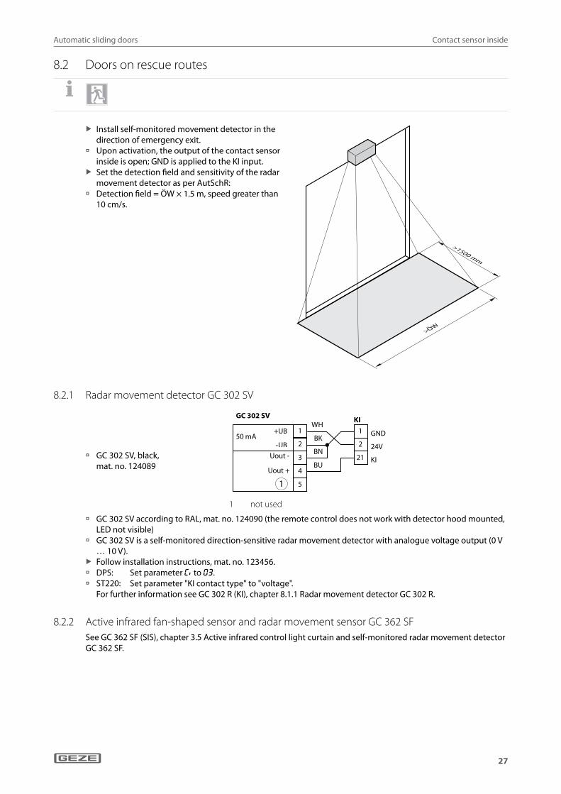
X Install self-monitored movement detector in the direction of emergency exit.
à Upon activation, the output of the contact sensor inside is open; GND is applied to the KI input.
X Set the detection field and sensitivity of the radar movement detector as per AutSchR:
à Detection field = ÖW × 1.5 m, speed greater than 10 cm/s.
8.2.1 Radar movement detector GC 302 SV
à GC 302 SV, black, mat. no. 124089
24V
KI
GNDWH
BU
BK
BN
50 mA +UB
-UB
GC 302 SV
2
21
1 1
2
3
4
5
KI
Uout -
Uout +
1
1 not used
à GC 302 SV according to RAL, mat. no. 124090 (the remote control does not work with detector hood mounted, LED not visible)
à GC 302 SV is a self-monitored direction-sensitive radar movement detector with analogue voltage output (0 V … 10 V).
X Follow installation instructions, mat. no. 123456. à DPS: Set parameter cI to 03. à ST220: Set parameter "KI contact type" to "voltage".
For further information see GC 302 R (KI), chapter 8.1.1 Radar movement detector GC 302 R.
8.2.2 Active infrared fan-shaped sensor and radar movement sensor GC 362 SFSee GC 362 SF (SIS), chapter 3.5 Active infrared control light curtain and self-monitored radar movement detector GC 362 SF.
Automatic sliding doors
28
Contact sensor outside
9 Contact sensor outside à The KA input is only active in operating mode aU. à During activation, the output of the contact sensor outside is closed (24 V applied at the KA input).
9.1 Radar movement detector GC 302 R
à See GC 302 R (KI), chapter 8.1.1 Radar movement detector GC 302 R.
WH
BU
BK
BN
85 mA +UB
-UB
GC 302 R
2
1
3
4
5
24V
KA
GND
2
23
1 KA
9.2 Active infrared fan-shaped sensor GC 363 RSee GC 363 R (SIS), chapter 6.1.1 Active infrared control light curtain (GC 339, GC 333) with safety/activation sen-sor (GC 363 R, GC 362 R).
9.3 Active infrared fan-shaped sensor and radar movement detector GC 362 RSee GC 362 R (SIS), chapter 6.1.1 Active infrared control light curtain (GC 339, GC 333) with safety/activation sen-sor (GC 363 R, GC 362 R).
9.4 Push button (potential-free contact)
à See push button (KI), chapter 8.1.4 Push button (potential-free contact).
23 KA
2 24VKA
10 Stop
cN = 01
1,2 k 2,0 k1,2 k 2,0 k
STOP24V2
15 STOP2,0
k
STOP24V2
15 STOP1,2
k
STOP24V2
15 STOP2,0
k
STOP24V2
15 STOP1,2
k
With DPS: cN = 01 cN = 02 cN = 12 cN = 20
With ST220:
STOP contact type = closer
STOP contact type = opener
STOP contact typeTerminating 1.2 kΩ
TerminatingTerminating 2.0 kΩ
For personal protection as per DIN 18650 and EN 16005: X Connect terminating resistance to monitor the input in accordance with the configuration.
Automatic sliding doors
29
Programmable inputs
11 Programmable inputsThe control features three programmable inputs, PE1 (terminal 51), PE2 (terminal 52) and PE3 (terminal 22), that can be allocated different control functions. The inputs can be programmed using the display programme switch DPS or the service terminal ST220. The functions are described in the Service menu DPS section (2nd menu) and in the Service terminal ST220 section (Configurable inputs).
11.1 Switch function
à With DPS: Set e1, e2 or e3 to 10 (switch function) or 11 (switch function with closing after hold-open time).
à With ST220: Set PE1-, PE2- or PE3-function to "switch function" or "switch function OHZ".
�� �� �
� ���
�� ��� ��
�� �� �
�� ��� ��
����
�� �� �
�� �
����
à During activation, the push button is closed (24 V is applied to inputs PE1, PE2 and PE3). à The first switch contact opens the door and the next closes the door. à For the switch function with closing after the hold-open time, the door closes automatically after the hold-
open time elapses providing it was not closed via the switch beforehand. X Check whether the door always opens completely with switch contact even if the operating mode "AU" winter
is set.
11.2 Radio activation à Follow installation instructions and user manual. à Parameter setting of contact type with:
à DPS: Set E1, E2 or E3 to the required function (8, 9, 10, 11, 14). à ST220: Set "input signals", "configurable inputs", "PE1 function", "PE2 function" or "PE3 function" to the
required function.
Push button with transmitting module
1
WRM-24
OUT1
GN
24V
PE1
D
51
24V
GND
2
24V 2
A
OUT2
2
B
GND 1
PE1, PE2
24V
PE2
GND
2
52
1 1 PE1, PE2ode
24V
PE3
GND
2
22
1 PE3oderr
à The receiving module WRM-24 can be activated with the transmitting module WTM.
à Transmitting module WTM, mat. no. 131212, for clipping into a plastic elbow switch.
à Follow the installation instructions for the wireless pro-gramme AUT.
WTM
BN
GN
YE
or or
or or

Automatic sliding doors
30
Programmable inputs
11.3 Pharmacy opening
X Set function parameter for input used: à With DPS: Set e1, e2 or e3 to 06. à With ST220: Set "PE1-", "PE2-" or "PE3-func-
tion" to "pharmacy".
51 PE 1
2 24V
PE 1 P E 2
52 PE 2
PE 1 P E 2oder
2 24V
22 PE 3
PE 3oder
2 24V
à During activation, 24 V is applied to the input. à The pharmacy opening function is only active in the Na operating mode. X Use a push button as the activation element.
11.4 Emergency lock
X Set parameter for input (terminal) used: à With DPS: Set e1, e2 or e3 to 07. à With ST220: Set "PE1-", "PE2-" or "PE3-function" to
"emergency lock". 22 PE 3
2 24V
2 24V
PE 3
51 PE1
PE 1 P E 2oder
2 24V
52 PE2
PE 1 P E 2oder
à The door closes and locks as soon as the contact is closed. à 24 V are applied to the control. à The door remains closed and locked as long as the contact is closed.
à When the emergency lock is active, the safety sensors "close" (SIS) and obstruction detection are not active.
or or
or or
Automatic sliding doors
31
WC control
12 WC control(not with DCU1-2M)
Setting the parameters with: à DPS:
à Set E1, E2 or E3 to 21 (WC control), depending on the input used. à Set A1 to 14 (LS). à Set A2 to 24 (fault WC timeout) if monitoring of permanent locking is required (signal horn to the lodge) à Set AC to 01 (open) or 03 (battery operation max. 30 minutes / 30 cycles, then open).
à ST220: à Set "input signals", "PE1-function", "PE2-function" or "PE3 function" to "WC control". à Set "output signals", "PA1 function" to "shop closing". à Set "Door parameters", "Power failure not NA" to "open" or "30 min open".
Accessories: à AS 500 switch unit with illuminated display for disabled WC, mat. no. 120882 (2 units required) à Optional: SLH220, SIGNAL HORN, flush-mounted, AS 500, AW, COMPLETE, mat. no. 115939
Push button with illuminated display "occupied"
1
2
2
3
GND 1
2 24V
55
56
PA1 PA2
57
PA1A
PA1B
PA2
KA
23 KA
2 24V
PE1, PE2
51 PE1
2 24V 52 PE2 22 PE3
oder oder
–
–
+
+
1 Inside push button (switch unit with illuminated display)2 OCCUPIED3 Outside push button (switch unit with illuminated display)
FunctionThe control recognises the operating function "WC control" on the basis of the parameter set for the configurable input (PE1, PE2, PE3). If the WC is not occupied, the door is in automatic mode and is in the closed position. The OCCUPIED signs are off. When the "outside push button" is activated, the WC door is opened. Once someone has entered the cubicle, the WC door is switched to shop closing mode by pressing the "inside push button" and the outside push button is blocked. The OCCUPIED signs light up. The drive keeps the door locked in the closed position by means of motor power. Pressing the "inside push button" again switches the operating mode back to automatic. The OCCUPIED signs go out. The door opens and the "outside push button" is cleared again. When WCs are monitored for permanent locking, the "WC alarm" signal is triggered after 30 minutes and an acoustic signal (signal horn to the gate) is switched on. The time cannot be set.In an emergency, the toilet door can be opened from the outside using the emergency opening switch. In the event of power failure, the door opens or remains in operation for max. 30 minutes or 30 cycles and then opens, depending on the AC parameter setting (power failure not NA).
or or

Automatic sliding doors
32
Interlocking door system, vestibule
Signal horn
GND 1
2 24V
55
56
PA1 PA2
57
PA1A
PA1B
PA2
+
-
1
1 Signal horn SLH220 to the lodge (optional)
Emergency opening switchSee "emergency opening switch", chapter 7 Contact sensor authorised.
13 Interlocking door system, vestibule
à Two sliding doors use the same programme switch. à The programme switch only indicates the fault messages of the
first control. à Interlocking door system: One door only opens if the other one
is closed. à Vestibule: Both doors run in the same mode of operation. X Do not connect terminal 2. The programme switch is connected
to the first control.
X Set parameters with DPS: à First control: sl = 00 à Second control sl = 01 for interlocking door system
sl = 02 for vestibule
1 GND
2 24V
42RS485 -A
41RS485 -B
43SCR
RS485
GND1
2 24V
42 RS485 -A
41 RS485 -B
43 SCR
RS485
1 2
1 Control door 12 Control door 2
X Set parameters with ST220: à First control: "Interlocking door system vestibule = Master" à Second control: "Interlocking door system vestibule = Slave interlocking door system"
for interlocking door system "Interlocking door system vestibule = Slave vestibule" for vestibule

Automatic sliding doors
33
Mode of operation
14 Mode of operation à For sliding doors on rescue routes, the programme switch must be protected from unauthorised access e.g. by
using a lockable version. à The display programme switch DPS, the service terminal ST220 or GEZEconnects (mat. no. 133367) is required
for setting control parameters and commissioning the door drive.
Symbol Display Explanation
OFFOFF SERVICE
(only valid for mat. no. 151524 and 155810 in combination with DCU V3.3)The drive is switched to without function for service purposes.The door leaves can be moved freely by hand.Activation and safety sensors are without function.Drive motor and locking are switched off.
nA NIGHTThe door is closed and locked. The door can only be opened while mode “contact sensor authorised (KB)” is active or via manual release.
LS SHOP CLOSING (one-direction operation from the inside to the outside)The door can be activated using contact sensor inside (KI) and contact sensor authorised (KB). The safety sensors "close" (SIS) are active. When activated, the door opens up to a reduced opening width set during commissioning.
Au Winter AUTOMATIC with reduced opening width.Activation is possible with contact sensor inside (KI), contact sensor outside (KA) and contact sensor authorised (KB). The safety sensors "close" (SIS) are active. When activated, the door opens up to a reduced opening width set during commissioning.
do PERMANENTLY OPEN The door is completely opened.
Au Summer AUTOMATIC with full opening widthActivation is possible with contact sensor inside (KI), contact sensor outside (KA) and contact sensor authorised (KB). The safety sensors "close" (SIS) are active. When activated, the door opens up to full opening width.
14.1 Mechanical programme switch
The LED on the mechanical programme switch lights up after the service interval has expired or in the event of a fault. à MPS, AS 500, mat. no. 113226 à MPS-ST, with key, AS 500,
mat. no. 113227 à Accessories:
à Surface-mounted cap single, AS 500, mat. no. 120503
à Operating modes: à OFF, Na, ls, aU Winter, DO, aU Summer
X Follow installation instructions, (mat. no. 122611).
LED
X Set parameters for input/terminal PE2: à With DPS: e2 to 01 for MPS à With ST220: "PE2-function" to "MPS"
X Set parameters for output/terminal PA1 and PA2: à With DPS: Set a1 or a2 to 04 for fault display MPS. à With ST220: Set "PA1-" or "PA2-function" to "fault MPS".
à If the mechanical programme switch is used, it is not possible to change the operating mode using the keypad programme switch, display programme switch or the inputs Na, ls, aU and DO.
or

Automatic sliding doors
34
Mode of operation
14.2 Switching the operating mode using push buttons or switches
In addition, it is possible to change between the operating modes Na, aU, ls, DO and "OFF" using potential-free push buttons or switches.
X For the operating mode "OFF" the func-tion parameter must be set for the input used.
If the drive is switched to the OFF operat-ing mode, the door opens before the drive switches off.
24V2
6 NA
7 LS
8 AU
9 DO
PS
PE 1 P E 2 PE 1 P E 2 PE 3
52 52
oder oder
PE1 PE2 22 PE3OFF
à With DPS: Set e1, e2 or e3 to 02. à With ST220: Set "PE1-", "PE2-" or "PE3-function" to "OFF".
à The control switches to the desired operating mode if the level switches from GND to 24 V at the correspond-ing input.
à Operation using the keypad programme switch or display programme switch is only possible if there is no signal pending at the inputs Na, aU, ls and DO.
à Locking the door (changing to operating mode Na) using a potential-free push button or switch is not pos-sible for doors on rescue routes.
14.3 Keypad programme switch
à TPS, AS 500, flush-mounted, mat. no. 113231 à TPS SCT, AS 500, flush-mounted, with key
push button, without profile half cylinder, mat. no. 113232
LEDs (1) for operating mode display indicate a fault code when a fault has occurred (see fault messages keypad programme switch).LED (2) lights up with reduced opening width. à Operating modes:
à OFF, Na, ls, aU, DO, Summer / Winter à Operation of the programme switch can be
blocked for unauthorised persons by using a key push button or assigning a password (see chapter 14.8).
No TPS can be connected when PE2-function is "MPS" (only display possible).
X Follow installation instructions, mat. no. 122400.
à Accessories: à Profile half cylinder, mat. no. 090176 à Additional contact, mat. no. 024467 à Surface-mounted cap single, AS 500,
mat. no. 120503 à Surface-mounted cap double, AS 500,
mat. no. 128609
2
1
1
44
41
42
G ND1
2 24V
42 R S 485-A
41 R S 485-B
S C R43
R S 48570 mA
20 K B
3 24VA K K U
Zus atzkontakt K B 1 2
3
1 LEDs for operating mode display2 LED for reduced opening width3 Additional contact
or or
Automatic sliding doors
35
Mode of operation
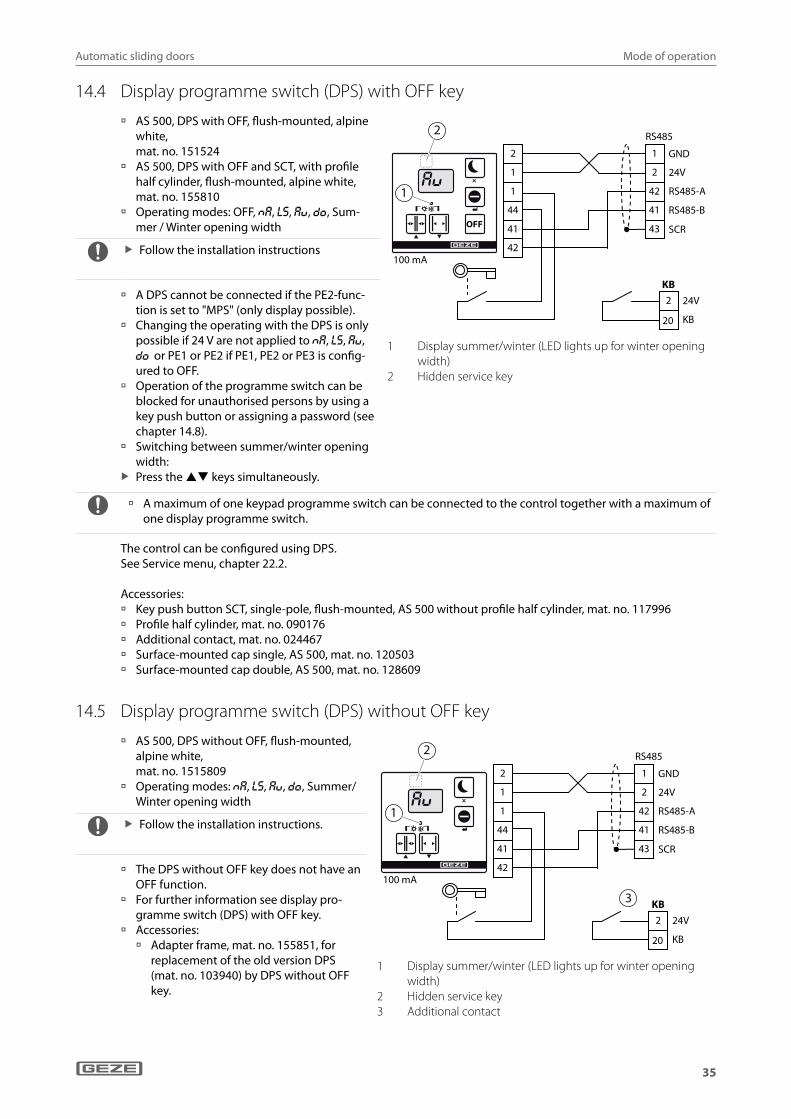
14.4 Display programme switch (DPS) with OFF key
à AS 500, DPS with OFF, flush-mounted, alpine white, mat. no. 151524
à AS 500, DPS with OFF and SCT, with profile half cylinder, flush-mounted, alpine white, mat. no. 155810
à Operating modes: OFF, Na, ls, aU, DO, Sum-mer / Winter opening width
X Follow the installation instructions
à A DPS cannot be connected if the PE2-func-tion is set to "MPS" (only display possible).
à Changing the operating with the DPS is only possible if 24 V are not applied to Na, ls, aU, DO or PE1 or PE2 if PE1, PE2 or PE3 is config-ured to OFF.
à Operation of the programme switch can be blocked for unauthorised persons by using a key push button or assigning a password (see chapter 14.8).
à Switching between summer/winter opening width:
X Press the keys simultaneously.
2
1
1
44
41
42
GND1
2 24V
42 RS485-A
41 RS485-B
SCR43
RS485
100 mA
OFF
2
1
20 KB
2 24V
KB
1 Display summer/winter (LED lights up for winter opening width)
2 Hidden service key
à A maximum of one keypad programme switch can be connected to the control together with a maximum of one display programme switch.
The control can be configured using DPS.See Service menu, chapter 22.2.
Accessories: à Key push button SCT, single-pole, flush-mounted, AS 500 without profile half cylinder, mat. no. 117996 à Profile half cylinder, mat. no. 090176 à Additional contact, mat. no. 024467 à Surface-mounted cap single, AS 500, mat. no. 120503 à Surface-mounted cap double, AS 500, mat. no. 128609
14.5 Display programme switch (DPS) without OFF key
à AS 500, DPS without OFF, flush-mounted, alpine white, mat. no. 1515809
à Operating modes: Na, ls, aU, DO, Summer/ Winter opening width
X Follow the installation instructions.
à The DPS without OFF key does not have an OFF function.
à For further information see display pro-gramme switch (DPS) with OFF key.
à Accessories: à Adapter frame, mat. no. 155851, for
replacement of the old version DPS (mat. no. 103940) by DPS without OFF key.
2
1
1
44
41
42
GND1
2 24V
42 RS485-A
41 RS485-B
SCR43
RS485
100 mA
2
1
20 KB
2 24V
KB
3
1 Display summer/winter (LED lights up for winter opening width)
2 Hidden service key3 Additional contact

Automatic sliding doors
36
Mode of operation
14.6 Display programme switch, old version (mat. no. 103940)The old version of the DPS can still be connected.Connection and function as with the display programme switch without OFF key.
14.7 Reset function (DPS with OFF key, TPS)In the OFF operating mode, the keys and can be pressed at the same time to trigger a software reset. The drive then behaves in the same way as after mains voltage switch-on and carries out initialisation. The parameter settings are not changed.
The reset function is not possible with the DPS without OFF key.
14.8 Blocking or releasing operation of TPS and DPS
14.8.1 With additional key push button (1st possibility)
With automatic standard sliding doors X Press the key push button briefly to block function.
à With the DPS, the operation lock is signalled by the display "- -" when any key is pressed. à With the TPS, the operation block is signalled by the LED for the respectively set operating mode flashing
once when any key is pressed. X Press the key push button again briefly for release. Operation is then permanently released.
For automatic sliding doors on escape and rescue routes X The key push button has to be activated permanently to unlock the operation. X Operation is blocked as soon as the key push button is no longer pressed.
à With the DPS, the operation lock is signalled by the display "- -" when any key is pressed. à With the TPS, the operation block is signalled by the LED for the respectively set operating mode flashing
once when any key is pressed.
14.8.2 Release with password (2nd possibility) This requires previous setting of the 2-digit password in the drive Service menu (factory setting: no password). à For release on the TPS: X Enter the first digit of the password by the number of times the key is pressed, with
à TPS: Key à DPS: Key aU
X Enter the second digit of the password by the number of times the key is pressed, with à TPS: Key à DPS: Key DO
à After the password has been entered, operation of the programme switch has been released. à Operation is blocked automatically 2 minutes after the last key has been pressed. With the TPS, the operation
block is signalled by the LED for the respectively set operating mode flashing once when any key is pressed. With the DPS, the operation lock is signalled by the display "- -" when any key is pressed.
14.8.3 Permanent release of programme switch operation X For permanent release, either fit a jumper between terminals 1-44 of the TPS or DPS
or X set the value "00" (factory setting) as the password in the Service menu.

Automatic sliding doors
37
Configurable outputs
15 Configurable outputsThe control indicates various states via the two configurable outputs PA1 and PA2 (see Service menu). The out-puts must be configured accordingly.
15.1 PA1 (gong)
PA1 is a potential-free relay contact, switching voltage/current max. 24 V AC/DC / 0.5 A.
X Set parameters for the gong function: à With DPS: Set a1 or a2 to 01. à With ST220: Set "PA1-" or "PA2-function" to "Gong".
The contact closes as soon as SIS1 or SIS2 is activated.
55 PA1A
56 PA1B
PA1 PA2
3
2
1
1 Gong2 Bell transformer3 Feeder
15.2 PA2 (fault, fan)
PA2 is a transistor output, switching voltage/current max. 24 V DC / 0.5 A.
PA1 PA2
57 PA2
2 24V
X Set parameters for fault indication: à With DPS: Set a1 or a2 to 02. à With ST220: Set "PA1-" or "PA2-function" to "Fault closer".
The output switches to GND as soon as the control detects a system fault. At the same time, the corresponding fault number is displayed on the display programme switch or keypad programme switch.
X A relay for galvanic isolation must be installed for forwarding the fault message (e.g. to a building manage-ment system).
X Set parameters for the use of a fan for cooling the motor: à With DPS: Set a1 or a2 to 07. à With ST220: Set "PA1-" or "PA2-function" to "Motor fan".
à Motor fan for Slimdrive, mat. no. 80533 à Motor fan for Powerdrive, mat. no. 123394

Automatic sliding doors
38
Mains connection
16 Mains connection à Transformer for Slimdrive, mat. no. 106194 à Transformer for ECdrive, mat. no. 106530 à Transformer for Powerdrive, mat. no. 117975
BK
BU
GN/YE
L
N
PE
PE
1
3
2
4
BK
BU
GN/YE
BK
BU
GN/YE
AC IN
AC
PE
AC
GN
BN
BK
PE
N
L T2A
DCU1 230V 50Hz
1
2 3 4
5
6
1 Mains fuse on site, min. 4 A slow-burning2 Main switch (optional)3 Transformer4 Control5 Cover earthing6 Earthing connection
Automatic sliding doors
39
Locking
17 Locking
17.1 Locking by toothed belt à Locking by toothed belt Slimdrive SL, SLT, SL NT, mat. no. 114004 à Locking by toothed belt Slimdrive SC, mat. no. 105275 à Locking by toothed belt ECdrive, mat. no. 117766 à Locking by toothed belt Powerdrive, mat. no. 114000
WH
BN
GN
YE
GY 6 Entriegelt
5 Verriegelt
2 24V
4 Riegel A
3 Riegel B
1 GND
LOCK
LK
S1
2
1
BK
RD
BK
BK
WH
BN
GN
YE
C
NO
NCS3
LCK B
LCK A
LKD
ULKD
à Shown in unlocked state. à Switch S3, mat. no. 019080, can be installed optionally,
switching voltage/current max. 24 V AC/DC / 0.5 A. à In the locked state, switches S1 and S3 are activated and the contact of switch S1 is opened.
17.2 Rod locking, break axle
à Rod locking Slimdrive SL, SLT, mat. no. 105680
à Break axle Slimdrive SF, mat. no. 107574
GY
YE
BN
WH
GN 2 24V
3 Riegel B
4 Riegel A
5 Verriegelt
6 Entriegelt
1 GND
LOCK
BN
WH
WH
GY
YE
BN
WH
GN
WH
BN
GN
YE
S3
YE
S4
S2 S1
M
ULKD
LKD
LCK A
LCK B
à Shown in unlocked state. à Switches S3 and S4, mat. no. 105684, can be installed optionally with break axle, switching voltage/current
max. 24 V AC/DC / 0.5 A. à In the locked state, switches S1 and S3 are activated, the contacts of switches S1 and S3 and the contacts of
switches S2 and S4 are opened.
The following rod lockings are used for drives with RC2: à 2-leaf SL RC2, without potential-free contact mat. no. 134044 à 2-leaf SL RC2, with potential-free contact mat. no. 136105 à 2-leaf SLC RC2, with potential-free contact mat. no. 140244 à 1-leaf, right closing SL RC2, with potential-free contact mat. no. 139769 à 1-leaf, left closing SL RC2, with potential-free contact mat. no. 139770

Automatic sliding doors
40
Rechargeable battery
17.3 Hook bolt Lock A à Hooked locking device Lock Basis 1 HRS, mat. no. 156679 à Depending on the drive, number of leaves and direction of closing movement, the following accessories are
used: à Lock A Integration EC 2-leaf, 1-leaf, right, mat. no. 153658 à Lock A Integration EC 1-leaf left, mat. no. 153660 à Lock A Integration SL NT 2-leaf, 1-leaf right, mat. no. 153671 à Lock A Integration SL NT 1-leaf left, mat. no. 153672
Set the parameters with:
Parameter Value DescriptionDPS E2 20 Manual unlocking
Rt 05 Lock A, hook bolt lockST220 Door parameters \ electric locking Lock A Hook bolt lock
Input signals \ PE2 Lock A Manual unlocking
DCU1LOCK
GND
24V
6
5YE
1
2
3WH
4
GY
BN
DCU1PE1, PE2
51PE1
2 24V
BK
MRD
WH
BN
2k49
7k27
24V
PK
YE
GY
GN
WH
BN
PK
YE
GY
GN
LOCK A
WH
BN
PK
YE
GY
GN52PE2
6
5
4
3
2
1
5
1
4
6
2345
Shown in "unlocked" state
1 Rod contacts (Lock A Integration)2 Bolt B3 Bolt A4 Locked5 Unlocked6 Manually unlocked
18 Rechargeable battery
Rechargeable battery, mat. no. 106863 à Voltage in charged state: ≥26 V (with recharge-
able battery unplugged).
BK
AKKU
GND
UAKKU+ - RD24 V
Automatic sliding doors
41
Motor
19 Motor
Motor 1: Motor DCU1, mat. no. 105009.
Motor 2: Only with tandem motor DCU1-2M, mat. no. 102517.
6 A
+
Motor 1M
3 Schirm2
1Motor_B
Motor_A
M1
Temperaturfühler
1
2
Encoder
WH
GN
YE
BK
BN
RD
OG
1 Schirm
2 Thermo
3 GND
4 GND
5 5V
7 B
Encoder
Motor 2M
1 Schirm2
3
Motor_B
Motor_A
M2
+
WH
BN
WH
BN
ENC
Temp
SHLD
SHLD
M1 B
M1 A
SHLD
M2 B
M2 A
ENC
2
1
3
–
–
1 Temperature sensor2 Motor 13 Motor 2

Automatic sliding doors
42
Control
20 Control
Control DCU1, mat. no. 105010.Terminal bag, mat. no. 106047.
Control DCU1-2M, mat. no. 105011.Terminal bag, mat. no. 106047.
F5 F4
DCU100
M2 DCU101
à DCU100: à F1 24 V EXT (1.25 AT, 5x20 mm) à F2 AC IN (6.3 AT, 5x20 mm) à F3 rechargeable battery (6.3 AT, 5x20 mm) à RUN Run-LED
à DCU101: à F4 AC IN (6.3 AT, 5x20 mm) à F5 rechargeable battery (6.3 AT, 5x20 mm)
DCU103 1 2 3
CAN
à DCU103 à 1-2 CAN terminating resistance inactive à 2-3 CAN terminating resistance active
à RUN-LED à LED on: Everything OK. à LED flashes slowly (0.25 Hz): Drive not taught. à LED flashes quickly (2 Hz): Fault.
LOCK
PR
OG
DCU103
F3
DCU101
M1 ENCODER M1_TEMP
RS485 KBKA KI
SIS1 SIO1 PE3
SIO2 SIS2 PS STOP
RUN
PA1 PA2PE1 PE2
F2
DCU100
AC IN AKKU
µR
F1

Automatic sliding doors
43
Commissioning and service
21 Commissioning and serviceCommissioning and service can be carried out using the display programme switch DPS or the service terminal ST220.
21.1 Production testThe production test is used for functional testing of the power supply, control, motor, rechargeable battery and locking assembly groups (if present). The production test is carried out on the drive before it is installed on the wall and without sliding leaves.
DANGERDanger of fatal injury due to electric shock.
X Interrupt power supply.
X Connect power supply to 230 V AC and use an r.c.c.b. X Connect the rechargeable battery. X Lock the lock (if present) by hand. The bolt comb must fully engage in the toothed belt. X Connect the display program switch DCU1.
X Connect terminals 1 and 44 of the display programme switch.
X Reset the control to factory settings using cp, display programme switch indicates le. X Press the service key and aU simultaneously (see Service menu, operation DPS), the production test starts:
à p1 Locking unlocked. à p3 Motor rotates approx. 20 cm in one direction and then approx. 20 cm in the other direction. à p2 Locking locked. à p6 Test of whether a rechargeable battery is connected. à a0 Rechargeable battery not detected. à a1 Rechargeable battery detected.
à If a rechargeable battery is connected, it must be detected. It is only checked whether the rechargeable bat-tery is present and not whether the charge state of the battery is sufficient.
à If a fault occurs during the production test, the test is aborted and the fault displayed. X Press the key. X With ST220, start the production test via the Service menu under the item "Start production test yes". X Unplug the rechargeable battery after the production test and leave it unplugged until commissioning.
21.2 Commissioning
21.2.1 Assembly and installation à Installation is complete (see installation instructions of the corresponding sliding door drive). à Sensors are correctly configured and aligned. X Clear the sensor detection field.
à Electrical installation is complete. There are no cables in the travel path of the leaves and drivers. All cables have been secured with cable ties.
X Push leaves by hand from the closed position into the completely open position and back again. It must be possible to move them freely (movement force less than 100 N).
X Align lock. When the leaves are completely closed, the lock must be easy to lock and unlock by hand.

Automatic sliding doors
44
Commissioning and service
21.2.2 Commissioning with DPS
CAUTIONDanger of injury by opening door leaves during commissioning.
X Switch off all safety devices. X Step out of the travel path.
X If not yet installed, connect the display programme switch. A keypad programme switch or mechanical programme switch that is already connected will not interfere with commissioning with the display programme switch.
X To commission a sliding door on rescue routes, terminals 1 and 44 of the display programme switch must be connected or the connected key push button must be activated.
X If a sliding door on a rescue route is to be operated with reduced opening width, connect terminals 2 and 6 on the control DCU1-2M. For sliding doors on rescue routes, the reduced opening width must correspond to at least the required escape route width.
X Plug the rechargeable battery into the control. X Switch on 230 V at the transformer.
à After power supply has been restored, a brand-new control indicates the function le on the display pro-gramme switch, whereas a control that has already been in operation will indicate the mode of operation last used before the voltage supply was switched off.
X Configure control, in particular: à aT Drive type à ef Number of door leaves à ®T Bolt type à cI Contact sensor inside à s1, f1, s2, f2, s3, f3, s4, f4 safety sensors (function and contact type)
X Close the door up to approx. 5 cm. X Select the function le in the Service menu. X Teach the control by pressing the enter key.
CAUTIONThe leaves accelerate quickly when the leaf mass is being determined.
X Step out of the travel path.
à The door leaves open and close several times. The control determines the following parameters: à l0 Start teaching à l1 Test the rotary transducer à l3 Opening width, closing position à l2 Locking by toothed belt à l8 Friction à l4 Leaf mass à l6 Reduced opening width (with control DCU1-2M only when a jumper is connected to set the reduced
opening width on terminal strip PS between terminal 6 (NA) and terminal 2 (+24V)) à The leaves come to a standstill with l6. X Push the leaves by hand to the required reduced opening width and confirm ( ).
For doors on rescue routes, the reduced opening width must be larger than or the same size as the required escape route width (construction approval). The control limits the reduced opening width to at least 30 percent of the maximum opening width. à Automatic takeover of the current position occurs after 20 sec. only with control DCU1.
à l7 End of teaching X Conform to store the values determined ( ).
à If a fault occurs, the teaching process is aborted with the message el. X Display the faults by pressing e®, eliminate the cause and start teaching again. X Remove the connection between terminals 2 and 6 of the control again. X Change to operating mode.
à After a brand-new control has been taught, it automatically changes to operating mode aU. X Check the running behaviour of the door and adjust other parameters if necessary. X Clear fault memory Oe. X Unplug display programme switch if necessary.

Automatic sliding doors
45
Commissioning and service
21.2.3 Commissioning with ST220
CAUTIONDanger of injury from moving door leaves.The door leaves move during commissioning.
X Step out of the door leaf travel path.
X If a sliding door on a rescue route is to be operated with reduced opening width, connect terminals 2 and 6 on the control DCU1-2M.
à For sliding doors on rescue routes, the reduced opening width must correspond to the prescribed escape route width.
X Plug the rechargeable battery into the control. X Switch on 230 V at the transformer.
After power supply has been restored, a brand-new control indicates the function non-taught initialisation on the ST220. A control that has already been in operation will indicate the mode of operation last used before the volt-age supply was switched off.
X Configure control, in particular: à Number of leaves Number of door leaves à Drive type Type of drive à Locking electric Bolt type à KI Type of contact and delay contact sensor inside à SI1, SI2, SI3, SI4 Type of contact and function of the safety sensors
X Close the door up to approx. 5 cm. X Teach the drive by selecting "Start teaching -> yes".
à The door leaves open and close several times. The control determines the following parameters: à Teaching programme rotary transducer Check the rotary transducer à Teaching programme opening width Opening width, closing position à Teaching programme bolt test Toothed belt locking à Teaching programme movement force Movement force / friction à Teaching programme acceleration Leaf mass (the leaves accelerate quickly) à Red. opening width learning prog. With control DCU1-2M only when a jumper is connected to set the
reduced opening width on terminal strip PS between terminal 6 (NA) and terminal 2 (+24V). The leaves come to a standstill in the teaching programme "reduced opening width".
X Push the leaves to the required reduced opening width and confirm ( ) (automatic takeover of the current position after 20 s only with DCU1).
For doors on rescue routes, the reduced opening width must be larger than or the same size as the required escape route width (construction approval). The control limits the reduced opening width to at least 30 percent of the maximum opening width.
à Teaching programme quit teaching End of teaching X Conform to store the values determined ( ).
If a fault occurs, teaching is aborted with the message "fault during teaching". X Display the fault in the menu item "fault memory-current faults", eliminate the cause and start teaching again. X Remove the connection between terminals 2 and 6 of the control again. X Change to operating mode. After a brand-new control has been taught, it automatically changes to operating
mode AU. X Check the running behaviour of the door and adjust other parameters if necessary. X Clear the fault memory. X Unplug ST220.

Automatic sliding doors
46
Commissioning and service
21.2.4 Functional check for the automatic sliding door X Switch off drive at power switch and wait until battery relay switches off. X Switch the drive back on at the mains switch.
à Self-test runs. X With the ST220, choose the operating mode OFF or with DPS clear the motor f®. X Mount drive hood and turn locking pin back in if necessary. X With the ST220 select the operating mode aU or with DPS switch the motor on fO. X Check function and detection field of all safety sensors "close". X Check function and detection field of all safety sensors "open". X Check the function of all contact sensors. X Check locking by changing to operating mode Na and unlocking by changing to operating mode aU.
21.2.5 Commissioning the interlocking door system and vestibuleBoth controls are commissioned like two individual controls During the commissioning of one control, the other must be separated from the power supply.
X Set parameters, see Chapter 14 Interlocking door system, vestibule. X Switch off both controls.
à A programme switch is only connected to the first control. X Switch both controls on within 50 s.
21.2.6 Documentation X Create test log. X Carry out safety analysis and enter installed safety options into the safety analysis. X Supplement classification on identification plate.
21.3 Service
21.3.1 Service with DPSThe drive must be re-taught after changes have been made, particularly after the opening width has been changed.
X Check function and correct setting of all safety sensors. X Check function and correct setting of all activation sensors. X Read out number of cycles and operating duration (menu item sa). X Note faults in the fault memory e® and Oe. X Clear fault memory Oe. X Reset service display (cs).
21.3.2 Service with ST220The drive must be re-taught after changes have been made, particularly after the opening width has been changed.
X Check function and correct setting of all safety sensors. X Check function and correct setting of all activation sensors. X Read out number of cycles and operating duration:
à Menu item "Diagnosis current values internal values cycles/operating hours" X Read out fault memory and note faults:
à Menu item "Diagnosis fault memory current faults / old faults" X Select fault with * and confirm with ( ). Cause of fault is displayed. X Clear fault memory:
à Menu item "Diagnosis clear fault memory" X Reset service display:
à Menu item "Diagnosis clear maintenance yes"

Automatic sliding doors
47
Service menu
22 Service menu
22.1 Service terminal ST220 à Service terminal ST200, mat. no. 087261 à The drive can be commissioned with service terminal ST220, software version from v2.1.
22.1.1 Operation of ST220
Key FunctionCursor upwardsIncrease number valueScroll upward (if key is pressed longer than 2 s)
1
Cursor downwardsDecrease number value Scroll downward (if key is pressed longer than 2 s)
Cancel inputAny input can be aborted by pressing the key ×. The input position then changes to the first menu position or one menu level back.SelectUpdate display.Accept new value
Display immediately after connection
G E Z EService terminal
2.1XXXXXYWWJJZZZZZZV
Software version ST220 v2.1Serial number ST220
22.1.2 Service mode ST220 à The switch to service mode occurs with connection of the service terminal to DCU1. à Service is possible in operating modes LS, AU and DO. à In service mode, the door remains in operation in the current operating mode (not with teaching activated or
with Fo display).
Display after connection to the door control
SL NT 3.3 D1 DCU1_2M 1.6 D1 Automatic Summer Static
Drive type DCU100 Software version V3.3, hardware version D1
Additional PCB DCU101 DCU101 Software version V1.6, hardware version D1Mode of operation: Automatic
Season: Summer
Current operating mode (e.g. static condition) or fault message
22.1.3 Password prompt ST220If a password has been assigned in the menu "Diagnosis", "Change password", "Service 1", this is requested before the service menu can be entered.
Password0---*
X Enter the 4-digit password comprising figures and letters (0 … 9, A … Z, a … z) using the keys and . The position to be entered is indicated in the line below by the * symbol.
X Confirm entered position and change to next position using the key. X Abort entry using the key × . X After entering the password, confirm by pressing the key.
Automatic sliding doors
48
Service menu
22.1.4 Service menu ST220
Mode of operation
Designation Setting values Explanation
Mode of operation OFFNightShop closingAutomaticPermanently open
OFFNightShop closingAutomaticPermanently open
Current operating mode is displayed and can be changed.If an MPS is connected, it is not possible to change the operating mode via the ST220.
Season SummerWinter
SummerWinter
Full opening widthReduced opening width
Open doors - Key
Door parameters
Designation Setting values Explanation
No. of leaves Close on one sideClose centrally
Close on one sideClose centrally
–
Drive type UnknownSlimdrive SCSlimdrive SFSlimdrive SLSlimdrive SL NTSlimdrive SL BOSlimdrive SL CO48Slimdrive SLTSlimdrive SLVECdriveECdrive CO48Powerdrive PLECdrive BOTSA 360NT BOPowerdrive PL CO48Slimdrive SL NT-CO48Slimdrive SLT-CO48
UnknownSlimdrive SCSlimdrive SFSlimdrive SLSlimdrive SL NT
Slimdrive SLTSlimdrive SLVECdrive
Powerdrive PL
–
Drive serial no. 000000000000 000000000000 12-digit serial numberCurrent input position is marked with an asterisk. Select input position using or and confirm using .Then select number using or and confirm using .
Maintenance message after operating time
0, 1 … 12 … 99 0, 1 … 12 … 99 months0: no maintenance message
Maintenance message after cycles
0, 100,000 … 500,000…3,000,000
0, 100,000 … 500,000… 3,000,000
Cycles0: no maintenance messageCycle: open from closed position and close completely again.For DCU1-RD: Maintenance message presetting after 200,000 cycles.
Interlocking door system, vestibule
MasterSlave interlocking door systemSlave vestibule
Master Interlocking door system and vestibule:The same programme switch is used for two doors (DPS, TPS, MPS).Interlocking door system:Two doors – one only opens when the other is closed.
Power failure NA No functionOpen
No functionOpen
–
Automatic sliding doors
49
Service menu
Designation Setting values Explanation
Power failure not NA No function
OpenClose30 min. open
30 min. close
Open
Behaviour of the drive in case of a power failure in oper-ating modes LS, AU and DO.
Open and switch offClose and switch off30 min. max. 30 cycles with battery, then open and switch off.30 min. max. 30 cycles with battery, then close and switch off.
Battery fault No functionOpen Open Open and switch off in operating modes AU and LS.
Open in case of fault NoYes Yes The door opens in the event of a fault
(see fault list for details)Electric locking Without
BistableMotor-drivenWorking currentStatic currentLock A
WithoutBistableMotor-drivenWorking currentStatic currentLock A
Control is taught during commissioning whether or not a bistable lock is used. If a motor-driven lock is used, it must be configured before teaching, as otherwise a fault message will occur during teaching.Hook bolt lock
GEZE bus address 0, 1 … 63 0, 1 … 63 –
Movement parameters
Designation Setting values Explanation
Opening speed 03 04…10 12…20 25…50…80 cm/s Speed during opening *)
Closing speed 03 04…10 12…20 25…80 cm/s Speed during closing *)
Latching action open 00 01…07 cm/s 00 01…07 cm/s Final speed in the open positionLatching action closed 00 01…07 cm/s 00 01…07 cm/s Final speed in the closed positionReduced profile None
Open and closed
OpenClosed
NoneOpen and closed
OpenClosed
No reduced speedReduced speed before open position and closed posi-tionReduced speed before open positionReduced speed before closed position
Acceleration 1 … 20 …30 ×10 cm/s2 Acceleration and braking during opening and closing *)
*) The maximum speed and acceleration depend on the door weight and friction.
Stat. force open 10 20…150…250 N Maximum stat-ic force during opening
WARNING! Forces greater than 150 N can lead to serious physical injuries and are not permit-ted as per DIN 18650/EN 16005.
X Note that forces exceed-ing 150 N are only permit-ted if additional safety measures are taken.
Stat. force close 10 20…150…250 N Maximum static force during closing
Permanent closing pressure 00 01… 10 12…20 25 90 N Force with which the drive presses on the door leaf in the closed position.
Initial closing pressure 00 01… 10 12…20 25…120…150 N Initial closing pressure helps the door leaf slide into a rubber seal. It is applied for 0.7 sec. as soon as the closed position has been reached.
Summer hold-open time 00 01…10 12…20 25…60 s –

Automatic sliding doors
50
Service menu
Designation Setting values Explanation
Winter hold-open time 00 01…10 12…20 25…60 s –Hold-open time contact authorised
00 01…10 12…20 25…60 s –
Dyn. extension of hold-open time
NoYes
NoYes
Dynamic extension of hold-open time refers to the summer and winter hold-open times. If the door can-not close fully between 10 successive activations, the hold-open time is increased by one second, repeatedly if necessary. Once the door can close fully again, the configured hold-open time is used again.
Reversing limit 01 02…06…10 12…20 25 mm If the distance between the door leaves (single leaf: the distance between leaf and side part) during closing is smaller than the reversing limit, the door does not reverse if it hits an obstacle. It stops at the obstacle.
Input signals
Safety sensorsDesignation Setting values Explanation
SI1– terminal SIS1 current state
Indication of state, contact type and function
Safety device 1
SI1– terminal SIS1 type of contact
Not usedOpener
Not usedOpener
–
SI1 – terminal SIS1 function SIS revSIS and KISIS and KASIS slowSIO stopSIO slowSIO break-out
SIS revSIS and KISIS and KASIS slow
SIO slow
– SIS rev Door reversedSIS and KI Reversing during closing.
Activation function KI in the closed position.
SIS and KA Reversing during closing. Activation function KA in the closed position.
SIS slow Door brakes and contin-ues closing at a slower speed.
SIO stop Door stops during open-ing.
SIO slow Door brakes during open-ing and continues open-ing at slower speed.
SIO break-out Door stops when break-out leaves are broken out
SI2 – terminal SIS2 current state
Indication of state, contact type and function
Safety device 2
SIS slow
SI2 – terminal SIS2 contact type
Not usedOpener
Not usedOpener
–
SI2 – terminal SIS2 function SIS revSIS and KISIS and KASIS slowSIO stopSIO slowSIO break-out
SIS revSIS and KISIS and KASIS slow
SIO slow
–
SI3 – terminal SIO1 current state
Indication of state, contact type and function
Safety device 3
SI3 – terminal SIO1 contact type
Not usedOpener
Not usedOpener
–

Automatic sliding doors
51
Service menu
Safety sensorsDesignation Setting values Explanation
SI3 – terminal SIO1 function SIS revSIS and KISIS and KASIS slowSIO stopSIO slowSIO break-out
SIS revSIS and KISIS and KASIS slow
SIO slow
–
SI4 – terminal SIO2 current state
Indication of state, contact type and function
Safety device 4
SI4 – terminal SIO2 contact type
Not usedOpener
Not usedOpener
–
SI4 – terminal SIO2 function SIS revSIS and KISIS and KASIS slowSIO stopSIO slowSIO break-out
SIS revSIS and KISIS and KASIS slow
SIO slow
–
STOP current state Indication of state and contact type StopSTOP contact type Not used
CloserOpenerTerminating 1.2 kΩTerminating 2.0 kΩ
Not used If Stop is active, the door leaf brakes immediately and the drive clears.
In the case of connection with 1.2 kΩ or 2.0 kΩ the signal is monitored for short-circuit and cable breakage.
Activation sensorsDesignation Setting values Explanation
KB current state Indication of state, contact type Contact sensor authorisedKB contact type Not used
CloserNot usedCloser
–
KI current state Indication of state, contact type and activa-tion delay
Contact sensor inside
KI contact type Not usedCloserOpenerVoltageFrequency
OpenerVoltageFrequency
Voltage Movement detector with voltage output
Frequency Movement detector with frequency output
KI delay 0 1…10 s 0 s –KA current state Indication of state, contact type and activa-
tion delayContact sensor outside
KA contact type Not usedCloserOpenerFrequency
Not usedCloserOpenerFrequency
–
KA delay 0 1…10 s 0 1…10 s –
Automatic sliding doors
52
Service menu
Operating mode switcho-verDesignation Setting values Explanation
NA current state Indication of state and contact type
– Night; the operating mode cannot be changed as long as this is active.
NA contact type Not usedCloserOpener
Not used –
LS current state Indication of state and contact type Shop closing; the operating mode cannot be changed as long as this is active.
LS contact type Not usedCloserOpener
Not usedCloserOpener
–
AU current state Indication of state and contact type Automatic; the operating mode cannot be changed as long as this is active.
AU contact type Not usedCloserOpener
Not usedCloserOpener
–
DO current state Indication of state and contact type Permanently open; the operating mode cannot be changed as long as this is active.
DO contact type Not usedCloserOpener
Not usedCloserOpener
–
Configurable inputsDesignation Setting values Explanation
PE1 current status Indication of state and function OFF Operating mode "off"; the operating mode cannot be changed as long as this is active. With the DCU1-2M, the door opens before it switches off.
PE1 function Not usedOFF NOSummer NOWinter NOSabotage NCPharmacy NOEmergency lock NOP-KI activation NOP-KA activation NOPush button NOOHZ push button NOReset push button NODouble push button NOWC control NO
Not usedOFF NOSummer NOWinter NOSabotage NCPharmacy NO
P-KI activation NOP-KA activation NOPush button NOOHZ push button NOReset push button NODouble push button NO
Summer As long as this is active, the season cannot be changed.Winter
Sabotage In NA active: Door does not open again until sabotage is inactive and operating mode has been changed.
Pharmacy In NA: first flank opens 10 cm and locks, second closes and locks.
MPS An operating mode change via TPS, DPS or the operating mode inputs NA, LS, AU, DO and OFF is not pos-sible.
PE2 current state Indication of state and function Emergency lock
The door closes if this is active. Activation and safety sensors are inactive.

Automatic sliding doors
53
Service menu
Configurable inputsDesignation Setting values Explanation
PE2 function Not usedMPSOFF NOSummer NOWinter NOSabotage NCPharmacy NOEmergency lock NOP-KI activation NOP-KA activation NOPush button NOOHZ push button NOReset push button NODouble push button NOManual unlocking NOWC control NO
Not usedMPSOFF NOSummer NOWinter NOSabotage NCPharmacy NOEmergency lock NOP-KI activation NOP-KA activation NOPush button NOOHZ push button NOReset push button NODouble push button NOManual unlocking NO
P-KI activa-tion
Only active in operating mode LS and AU (like KI).
P-KA activa-tion
Only active in operating mode AU (like KA).
Push but-ton
The first flank opens completely, the next flank closes the door.
OHZ push button
The first flank opens completely, the next flank closes the door. If the hold-open time for contact sensor authorised expires while the door is open, the door closes automatically.
KI2 If the contact type KI is configured as opener for DCU1-2M, PE3 is the sec-ond contact sensor input and cannot be configured freely.
PE3 current state Indication of state and function Reset push button
The control is rebooted.
PE3 function Not used
OFF NOSummer NOWinter NOSabotage NCPharmacy NOEmergency lock NOP-KI activation NOP-KA activation NOPush button NOOHZ push button NOReset push button NODouble push button NOWC control NO
Not usedKI2 NOOFF NOSummer NOWinter NOSabotage NCPharmacy NOEmergency lock NOP-KI activation NOP-KA activation NOPush button NOOHZ push button NOReset push button NODouble push button NO
Double push but-ton
Press 1×: reduced opening widthPress 2×: full opening width

Automatic sliding doors
54
Service menu
Output signals
Configurable outputsDesignation Setting values Explanation
PA1 current state – Gong Active if an SIS is activated in AU, LS or DO.
PA1 function Not usedGongFault closerFault openerFault MPSWarnMotor brakeMotor fanLocked closedClosedNot closedOpenOffNightShop closingAutomaticPermanently openLight controlOpens Does not openMaintenance dueF-manual unlockingF-WC timeout
Not usedGongFault closerFault openerFault MPSWarn
Motor fanLocked closedClosedNot closedOpenOffNightShop closingAutomaticPermanently openLight control
Maintenance dueF-manual unlockingF-WC timeout
Fault Collective fault message
Fault MPS For activation of the LED on the MPS: à Collective fault message à Maintenance message
Warn Active if the door continues mov-ing despite active safety device at reduced speed.
Motor brake
CO48 pre-setting with drive SL CO48 and ECdrive CO48.0.7 s after the closed position has been reached, the motor brake is energised to hold the rubber cable (relieves motor).
Motor fan Active if motor temperature is higher than 67°C
Open Active if leaf is in current open posi-tion
Light con-trol
Output is active following activation for the duration of activation + 1 s.
F-manual unlocking
Manual unlocking Lock A activated
F-WC time-out
WC locked for longer than 30 minutes
PA2 current status – Opens Interlocking door system can be entered
PA2 function Not usedGongFault closerFault openerFault MPSWarnMotor brakeMotor fanLocked closedClosedNot closedOpenOffNightShop closingAutomaticPermanently openLight controlOpens Does not openMaintenance dueF-manual unlockingF-WC timeout
Not usedGongFault closerFault openerFault MPSWarn
Motor fanLocked closedClosedNot closedOpenOffNightShop closingAutomaticPermanently openLight control
Maintenance dueF-manual unlockingF-WC timeout
Does not open
Interlocking door system is in use and can not be entered
Automatic sliding doors
55
Service menu
Diagnosis
Designation Setting values ExplanationCurrent values SI1, SI2, SI3, SI4
STOPKB, KI, KANA, LS, AU, DOPE1, PE2, PE3Bolt 1, bolt 2
V
PA1, PA2BoltTST
V
current Positioncurrent Motor currentMains voltageBattery voltage24 V internalDCU100 temperatureDCU101 temperatureMotor DCU100 temperatureCycles Operating hoursTests
mmAon/offVV°C°C°CHours
Current states SI1, SI2, SI3, SI4STOPKB, KI, KANA, LS, AU, DOPE1, PE2, PE3Bolt 1, bolt 2
The logical state of the signal is displayed (active, inactive, fault).
PA1, PA2BoltTST
Fault memory Current faultsOld faults
Ser. no., fault text, fault number
Select fault marked by * and press the key, reason for fault will be displayed.
Clear fault memory Clear current faultsClear old faults
–
Configuration Opening widthBolt typeRechargeable batteryLeaf mass
left/right, mm
without/700 mAhkg
TypeDate of manufactureTime of manufacture
–
Start production test yes/noStart teaching yes/noFactory setting yes/noClear maintenance yes/no Clear maintenance display

Automatic sliding doors
56
Service menu
Designation Setting values ExplanationChange password Password Service 1 Password old 0000
Password newPassword Service 1:for access to the service menu with ST220.Password TPS, DPS: is used to enable the TPS or DPS instead of enabling via a key push button. Access is blocked automatically after 2 minutes if no key has been pressed.The first figure indicates how often the key has to be activated and the second figure how often the key has to be activated to enable operation of the TPS / DPS.Entry of the password with ST200:
X Change figures using or . X Conform figure and change to next position
using . X Cancel with x. X Display of the current position by the asterisk
under it. X After entry, press to confirm the password.
After 2 minutes without keys being pressed or the next time the Service menu is requested, the password will be queried so that changes to the operating mode setting or the parameter settings can be made.
Important information: à When the password for ST220 is set, access to
the Service menu via DPS is no longer possible. à If the password has been forgotten, a special
flash file with which the password on the control can be reset to 00 has to be requested from GEZE.
à The password cannot be deleted by installing a new software version.
Language DeutschEnglishFrançaisItalianoEspanol
Language of the service terminal

Automatic sliding doors
57
Service menu
22.2 Display programme switch (DPS)The DPS can be used for commissioning and service. à for changing the drive parameters à for "teaching" the drive à for diagnosis
Key Function in service modeNa Night × Cancel and return to first
menu level
OFF
1
23
4
1 Service key2 Position unknown3 Lights up for maintenance4 Display summer/winter (LED lights
up for winter opening width)
ls Shop closing Confirm
aU Automatic Scroll up Increase value
DO Permanently open Scroll down Reduce value
OFFOff Off (Only with mat. no. 152524)
drive switched without function for service purposes (drive is not without voltage)
+ simultaneously
ChangeSummer (full opening width)Winter (reduced opening width)
– –
Service key (1) + simultane-ously
Change operating mode / service mode
Scroll function (DPS with OFF key, DPS without OFF key)In the Service menu, it is possible to scroll through the menu or value settings by pressing the or keys.
22.2.1 Service mode DPS à It is possible to change to the service mode in the operating modes Off, ls, aU and DO. à If no key is pressed for 5 minutes in service mode, the system automatically changes to operating mode (not
when fO is displayed). à In service mode, the door remains in operation in the current operating mode (not with teaching activated or
with fO displayed).

Automatic sliding doors
58
Service menu
22.2.2 Service menu DPS
1st menu
Display Explanation Setting valuesUo Opening speed 03 04…10 12…20 25…50 80 cm/s *)
Uc Closing speed 03 04…10 12…20 25…50 80 cm/s *)
so Latching action open 00 01…07 cm/ssc Latching action closed 00 01…07 cm/s DCU1-RD: 1 … 10 … 14Oh Summer hold-open time 00 01…10 12…20 25…60 sO® Winter hold-open time (reduced opening width) 00 01…10 12…20 25…60 sOs Hold-open time contact authorised 00 01…10 12…20 25…60 sOD Dynamic extension of the hold-open time 00 no
01 yesBo Acceleration 1…10 12…20 25…30 × 10 cm/s2 *)
(multiply value displayed by 10)U® Reduced profile 00 no reduced speed
01 reduced speed before open position and before closed position02 reduced speed before open position03 reduced speed before closed position
fo Static force open 01 10 15 20 25 × 10 N(multiply value displayed by 10)
WARNING!Forces greater than 150 N can lead to serious physical injuries and are not permit-ted as per DIN 18650/EN 16005.
X Note that forces exceeding 150 N are only permitted if additional safety measures are taken.
fc Static force closed 01 10 15 20 25 × 10 N(multiply value displayed by 10)
cf Permanent closing pressure 00 01… 10 12…20 25…50 60…90 cl Reversing limit 01 02…06…10 12…20 25 mmNe Switch to 2nd menu –
*) The maximum speed and acceleration depend on the door weight and friction.

Automatic sliding doors
59
Service menu
2nd Menu
Display Explanation Setting values
s1 Safety 1 contact type (terminal SIS1) 0002
not usedOpener
0002
not usedOpener
f1 Safety 1 function (terminal SIS1) 01020304050607
SIS revSIS and KISIS and KASIS slowSIO stopSIO slowSIO break-out
01020304
06
SIS revSIS and KISIS and KASIS slow
SIO slow
s2 Safety 2 contact type (terminal SIS2) 0002
not usedOpener
0002
not usedOpener
f2 Safety 2 function (terminal SIS2) 01020304050607
SIS revSIS and KISIS and KASIS slowSIO stopSIO slowSIO break-out
01020304
06
SIS revSIS and KISIS and KASIS slow
SIO slow
s3 Safety 3 contact type (terminal SIO1) 0002
not usedOpener
0002
not usedOpener
f3 Safety 3 function (terminal SIO1) 01020304050607
SIS revSIS and KISIS and KASIS slowSIO stopSIO slowSIO break-out
01020304
06
SIS revSIS and KISIS and KASIS slow
SIO slow
s4 Safety 4 contact type (terminal SIO2) 0002
not usedOpener
0002
not usedOpener
f4 Safety 4 function (terminal SIO2) 01020304050607
SIS revSIS and KISIS and KASIS slowSIO stopSIO slowSIO break-out
01020304
06
SIS revSIS and KISIS and KASIS slow
SIO slow
cN Stop contact type 0001021220
not usedCloserOpenerTerminating 1.2 kΩTerminating 2.0 kΩ
00 not used
cB Contact sensor authorised contact type 0001
not usedCloser
0001
not usedCloser
cI Contact sensor inside contact type 0001020304
not usedCloserOpenerVoltageFrequency
020304
Redundant openerVoltageFrequency
aI Contact sensor inside activation delay 00 01 … 10 s 00 scO Contact sensor outside contact type 00
0102
04
not usedCloserOpener
Frequency
000102
04
not usedCloserOpener
Frequencyaa Contact sensor outside activation delay 00 10 s 00 10 s

Automatic sliding doors
60
Service menu
Display Explanation Setting values
e1 Configurable input 1 00
02030405060708091011
131421
not used
Operating mode OFF NOSummer NOWinter NOSabotage NCPharmacy NOEmergency lock NOP-KI activation NOP-KA activation NOSwitch function NOSwitch function, close to Os NOReset push button NODouble push button NOWC control NO
00
0203040506
08091011
1314
not used
Operating mode OFF NOSummer NOWinter NOSabotage NCPharmacy NO
P-KI activation NOP-KA activation NOSwitch function NOSwitch function, close to Os NOReset push button NODouble push button NO
e2 Configurable input 2 000102030405060708091011
13142021
not usedMPSOperating mode OFF NOSummer NOWinter NOSabotage NCPharmacy NOEmergency lock NOP-KI activation NOP-KA activation NOSwitch function NOSwitch function, close to Os NOReset push button NODouble push button NOManual unlocking NOWC control NO
00010203040506
08091011
131420
not usedMPSOperating mode OFF NOSummer NOWinter NOSabotage NCPharmacy NO
P-KI activation NOP-KA activation NOSwitch function NOSwitch function, close to Os NOReset push button NODouble push button NOManual unlocking NO
e3 Configurable input 3 00
02030405060708091011
13142021
not used
Operating mode OFF NOSummer NOWinter NOSabotage NCPharmacy NOEmergency lock NOP-KI activation NOP-KA activation NOSwitch function NOSwitch function, close to Os NOReset push button NODouble push button NOManual unlocking NOWC control NO
00010203040506
08091011
131420
not usedContact sensor inside 2 NOOperating mode OFF NOSummer NOWinter NOSabotage NCPharmacy NO
P-KI activation NOP-KA activation NOSwitch function NOSwitch function; close to Os NOReset push button NODouble push button NOManual unlocking NO

Automatic sliding doors
61
Service menu
Display Explanation Setting values
a1 Configurable output 1 000102030405060708091011121314
not usedGongFault closerFault openerFault for MPSWarning signalMotor brakeMotor fanClosed and lockedClosedNot closedOpenOFFNALS
000102030405
0708091011121314
not usedGongFault closerFault openerFault for MPSWarning signal
Motor fanClosed and lockedClosedNot closedOpenOFFNALS
1516171819202124
AUDOLight controlOpens when activatedDoes not open when acti-vatedMaintenance dueManual locking faultWC timeout fault
151617
202124
AUDOLight control
Maintenance dueManual locking faultWC timeout fault
a2 Configurable output 2 0001020304050607080910111213141516171819202124
not usedGongFault closerFault openerFault for MPSWarning signalMotor brakeMotor fanClosed and lockedClosedNot closedOpenOFFNALSAUDOLight controlOpens when activatedDoes not open when acti-vatedMaintenance dueManual locking faultWC timeout fault
000102030405
0708091011121314151617
202124
not usedGongFault closerFault openerFault for MPSWarning signal
Motor fanClosed and lockedClosedNot closedOpenOFFNALSAUDOLight control
Maintenance dueManual locking faultWC timeout fault
Ne Switch to 3rd menu – –

Automatic sliding doors
62
Service menu
3rd Menu
Display Explanation Setting values
e® Currently pending faults CE Clear fault memory Clear fault memoryOe Old faults (the last 10 faults) CE Clear fault memory Clear fault memoryDI Diagnosis r0
r1A0A1xxyy
Without lockWith lockWithout batteryWith batteryLeaf weight (x 100 kg)+ leaf weight (x kg)
r0r1A0A1xxyy
Without lockWith lockWithout batteryWith batteryLeaf weight (x 100 kg)+ leaf weight (x kg)
sT Control type 000102
DCU1DCU1-RD *DCU1-T30 *
* Special software
20212223
DCU1-2MDCU1-2M-DUO *DCU1-2M-LL *DCU1-2M-RWS *
sa Operating duration (6-digit display) CoHoFo
Number of cycles / 100Operating hours / 4Number of self-tests
CoHoFo
Number of cycles / 100Operating hours / 4Number of self-tests
cs Switch off Service LED cS Displayed briefly for ac-knowledgement
cS Displayed briefly for ac-knowledgement
cp Restore factory setting – –f® / fO Enable/activate motor – –sp Language 00
01020405
DeutschEnglishFrançaisItalianoEspanol
0001020405
DeutschEnglishFrançaisItalianoEspanol
le Start teaching – –ep Software version e.g. St 20 for DCU1 V2.0 e.g. Ft 20 for DCU1-2M V2.0Ne Switch to 4th menu – –
4. Menu
Display Explanation Setting values
aT Drive type 000102030405060708091011121314
UnknownSlimdrive SCSlimdrive SFSlimdrive SLSlimdrive SL NTSlimdrive SL BOSlimdrive SL CO48Slimdrive SLTSlimdrive SLVECdriveECdrive CO48PowerdrivePowerdrive BOTSA 360NT BOPowerdrive PL CO48
0001020304
070809
11
UnknownSlimdrive SCSlimdrive SFSlimdrive SLSlimdrive SL NT
Slimdrive SLTSlimdrive SLVECdrive
Powerdrive
ef Number of door leaves 0102
Close on one sideClose centrally
0102
Close on one sideClose centrally
ac Power failure in LS, AU or DO 00010203
04
No functionOpenCloseBattery operation for 30 min., then openBattery operation for 30 min., then close
01 Open
Automatic sliding doors
63
Service menu
Display Explanation Setting values
eO Open after fault 0001
Door remains closedDoor opens after fault (see fault list for details)
01 Door opens after fault
®T Bolt type 0001
02
030405
No lockingBistable electromechanical lockingMotor-driven (rod locking, break axle)Closed-circuit current lockOpen-circuit current lockLock A (hook bolt lock)
0001
02
03
05
No lockingBistable electromechanical lockingRod locking, break axle
Closed-circuit current lock
Lock A (hook bolt lock)
sl Interlocking door system, vestibule 000102
MasterSlave interlocking door systemSlave vestibule
00 Master
ca CAN address (GEZE building system) 00 01…63 address 00 01…63 address

Automatic sliding doors
64
Fault messages
23 Fault messages
23.1 Display programme switchFor troubleshooting and fault descriptions see "Faults and measures for controls DCU1 and DCU1-2M", mat. no. 108104. Currently pending fault messages are displayed briefly in cycles (10 s) on the display programme switch during operation. In addition, they are also entered in the e® and Oe fault memo-ries.
Display Fault message Cause01 24 V Control defective.02 12 V DCU100 Control defective.03 230 V Power failure07 Fire alarm Smoke detector active or power failure.3)
08 Smoke alarm Smoke detector active.4)
10 Rotary transducer Rotary transducer signal faulty.11 Short-circuit DCU100 current through motor 1 too high.12 Motor DCU100 motor 1 defective.13 SIS1 Testing: Safety sensor "close" 1 faulty or activation
takes longer than 4 min.14 MPS Control cable break – mechanical programme switch15 Display programme switch No communication between control – display programme switch16 Locking Locking does not lock.17 Unlock Locking does not unlock.18 Bolt signal Signals locked and unlocked are sent simultaneously.19 SIS2 Testing: Safety sensor "close" 2 faulty or activation
takes longer than 4 min.25 Open Obstacle while opening. 2)
26 Initialisation Taught opening width is not reached.27 SIO1, SIO2 Safety sensor "open" or break-out sensor5) is active.6)
28 Motor relay DCU100 motor relay of the main PCB is defective.29 SIO2 SIO2 or break-out sensor5) is not switching or activation takes longer than 4 min.32 Sabotage Sabotage active. 6)
33 Interlocking door system, vestibule
Second drive is not reacting.1) 6)
34 TPS No communication between control – keypad programme switch35 Pharmacy Activation longer than 4 min.36 Control Redundancy: Internal redundancy fault of the control2)
37 KI1 Movement detector defective or activation longer than 4 min.38 KI2 Movement detector defective or activation longer than 4 min.2)
39 KA Activation longer than 4 min.40 KB Activation longer than 4 min.41 SIO1 SIO1 or break-out sensor5) is not switching or activation takes longer than 4 min.42 NOTVER Emergency lock is activated.1)
44 STOP STOP is active.1)
45 DCU100 drive hot Motor or control temperature main PCB higher than 110°C.46 Motor temp. sensor Motor temperature sensor defective.47 DCU100 temperature sensor Temperature sensor main PCB control defective.48 DCU100 drive overheated Motor or control temperature main PCB greater than 115 °C.50 DCU1-T30 Fault while testing DCU1-T30 expansion.3)
51 DCU1-2M-LL, DCU1-2M-RWS Fault on brake (outputs PA1/PA2 do not open).Emergency push button pressed (motor brake enabled via emergency button, door opens immediately).
53 Manual unlocking Lock A has been unlocked by hand.54 Communication DPS Interference of communication with DPS60 DCU100 Fault on the main PCB.61 Rechargeable battery Rechargeable battery flat.63 Software Software of the main PCB does not match software of additional PCB.2)
64 Open during testing Door not open in required opening time.2)

Automatic sliding doors
65
Fault messages
Display Fault message Cause65 Program sequence Fault in internal computer monitoring.2)
70 DCU101 Fault on the additional PCB.2)
71 DCU101 short-circuit Current through motor 2 too high.2)
72 DCU101 motor Motor 2 defective.2)
75 DCU101 control hot Control temperature additional PCB higher than 110°C.2)
77 DCU101 temperature sensor Temperature sensor control additional PCB defective.2)
78 DCU101 control overheated Motor or control temperature additional PCB higher than 115°C.2)
79 DCU101 motor relay Motor relay additional PCB defective.2)
90 Control Control defective.91 Rotary transducer, motor No pulses from rotary transducer.x.x Position Leaf position unknown (dot on left display).x.x Maintenance Maintenance requirement (number of cycles, operating hours, dot on right display).EL Teaching Fault during teaching of the control.8.8. Display programme switch No communication between control – display programme switch.
1 with DCU12 with DCU1-2M3 with DCU1-T304 with DCU1-RD5 with DCU1-BO6 with DCU1; with these faults on the DCU1 the door does not open if the parameter "Open in case of fault" is switched on.
23.2 Keypad programme switch
Display keypad programme switch
Designation Display display programme switch
– – – – – No operating voltage– – – x x Drive too hot 45, 46, 48, 75, 78– – x – x Position 26, x.x– – x x – SIS 13, 19– – x x x Motor 10, 11, 12, 71, 72– x – – x Activation takes longer than 4
min35, 36, 37, 38, 39, 40
– x – x x Interlocking door system, vesti-bule
33
– x x – – Rechargeable battery 61– x x x – Opening time too long 64x – – – x Alarm 07, 08, 32, 42, 44x – – x x DCU 104 50x – x – – SIO, BO 27, 29, 41x x – – – Power failure 03x x – – – Control 01, 02, 28, 47, 60, 63, 65, 70, 77, 79x x x – – Locking 16, 17, 18, 51
– LED offx LED on
à In addition, the following states are displayed: à Non-taught winter LED flashes continuously (1 sec. on, 3 sec. off). à Maintenance winter LED flashes continuously (0.5 sec. on, 0.5 sec. off). à Fault operating mode displayed for 5 sec., fault code for 2 sec. à Block active. Current mode LED flashes once if a key is pressed.

Automatic sliding doors
66

Automatic sliding doors
67

GermanyGEZE Sonderkonstruktionen GmbHPlanken 197944 Boxberg-SchweigernTel. +49 (0) 7930 9294 0Fax +49 (0) 7930 9294 10E-Mail: [email protected]
GEZE GmbHNiederlassung Süd-WestTel. +49 (0) 7152 203 594E-Mail: [email protected]
GEZE GmbHNiederlassung Süd-OstTel. +49 (0) 7152 203 6440E-Mail: [email protected]
GEZE GmbHNiederlassung OstTel. +49 (0) 7152 203 6840E-Mail: [email protected]
GEZE GmbHNiederlassung Mitte/LuxemburgTel. +49 (0) 7152 203 6888E-Mail: [email protected]
GEZE GmbHNiederlassung WestTel. +49 (0) 7152 203 6770 E-Mail: [email protected]
GEZE GmbHNiederlassung NordTel. +49 (0) 7152 203 6600E-Mail: [email protected]
GEZE Service GmbHTel. +49 (0) 1802 923392E-Mail: [email protected]
AustriaGEZE AustriaE-Mail: [email protected]
Baltic StatesGEZE GmbH Baltic States officeE-Mail: [email protected]
BeneluxGEZE Benelux B.V.E-Mail: [email protected]
BulgariaGEZE Bulgaria - Trade E-Mail: [email protected]
ChinaGEZE Industries (Tianjin) Co., Ltd.E-Mail: [email protected]
GEZE Industries (Tianjin) Co., Ltd.Branch Office ShanghaiE-Mail: [email protected]
GEZE Industries (Tianjin) Co., Ltd.Branch Office GuangzhouE-Mail: [email protected]
GEZE Industries (Tianjin) Co., Ltd.Branch Office BeijingE-Mail: [email protected]
FranceGEZE France S.A.R.L.E-Mail: [email protected]
HungaryGEZE Hungary Kft.E-Mail: [email protected]
IberiaGEZE Iberia S.R.L.E-Mail: [email protected]
IndiaGEZE India Private Ltd.E-Mail: [email protected]
ItalyGEZE Italia S.r.lE-Mail: [email protected]
GEZE Engineering Roma S.r.lE-Mail: [email protected]
PolandGEZE Polska Sp.z o.o.E-Mail: [email protected]
RomaniaGEZE Romania S.R.L.E-Mail: [email protected]
RussiaOOO GEZE RUSE-Mail: [email protected]
Scandinavia – SwedenGEZE Scandinavia ABE-Mail: [email protected]
Scandinavia – NorwayGEZE Scandinavia AB avd. NorgeE-Mail: [email protected]
Scandinavia – DenmarkGEZE DanmarkE-Mail: [email protected]
SingaporeGEZE (Asia Pacific) Pte, Ltd.E-Mail: [email protected]
South AfricaGEZE Distributors (Pty) Ltd.E-Mail: [email protected]
SwitzerlandGEZE Schweiz AGE-Mail: [email protected]
TurkeyGEZE Kapı ve Pencere SistemleriE-Mail: [email protected]
UkraineLLC GEZE UkraineE-Mail: [email protected]
United Arab Emirates/GCCGEZE Middle EastE-Mail: [email protected]
United KingdomGEZE UK Ltd.E-Mail: [email protected]
GEZE GmbHReinhold-Vöster-Straße 21–2971229 LeonbergGermany
Tel.: 0049 7152 203 0Fax.: 0049 7152 203 310www.geze.com