Embed Size (px)
DESCRIPTION
Automation System for Students Attendance using IRIS Report
Citation preview

Automation System for Students’ Attendance using IRIS Recognition System
Chapter 1
INTRODUCTION
Opening Doors
1
Automation System for Students’ Attendance using IRIS Recognition System
1.1 Overview of Biometric Technology
Identification of humans is a goal as ancient as humanity itself. As technology and
services have developed in the modern world, human activities and transactions have proliferated
in which rapid and reliable personal identification is required. Examples include passport control,
computer login control, bank automatic teller machines and other transactions authorization,
premises access control, and security systems generally. All such identification efforts share the
common goals of speed, reliability and automation. The use of biometric indicia for
identification purposes requires that a particular biometric factor be unique for each individual
that it can be readily measured, and that it is invariant over time. Biometrics such as signatures,
photographs, fingerprints, voiceprints and retinal blood vessel patterns all have significant
drawbacks. Although signatures and photographs are cheap and easy to obtain and store, they are
Impossible to identify automatically a person with assurance, and are easily forged.
Electronically recorded voiceprints are susceptible to changes in a person’s voice, and
they can be counterfeited. Fingerprints or handprints require physical contact, and they also can
be counterfeited and marred by artifacts. Human iris on the other hand is an internal organ of the
eye and is well protected, from the external environment. Yet it is easily visible from within one
meter of distance makes it a perfect biometric for an identification system with the ease of speed,
reliability and automation. In this project, we are going to experiment, implement, and most
importantly, look into the theory behind an Iris Recognition System, which is not only related to
the field of personal identification, and more specifically to the field of automated identification
of humans by biometric indicia. Biometric authentication has been receiving extensive attention
over the past decade with increasing demands in automated personal identification.
1.2 Objectives
The main aim of our project is to build an application based on IRIS of a particular
individual. This application will help to the faculty of college/institutes to maintain the
attendance of the students easily. This project will also easily monitor the monthly attendance for
each student and will reduce the teachers’ efforts.
2
Automation System for Students’ Attendance using IRIS Recognition System
1.3 Anatomy of Human Iris:
The iris is a thin circular diaphragm, which lies between the cornea and the lens of the
human eye. A side view of the iris is shown in Figure 1.1. The iris is perforated close to its centre
by a circular aperture known as the pupil. The function of the iris is to control the amount of light
entering through the pupil, and this is done by the sphincter and the dilator muscles, which adjust
the size of the pupil. The average diameter of the iris is 12 mm, and the pupil size can vary from
10% to 80% of the iris diameter.
The iris consists of a number of layers: the lowest is the epithelium layer, which contains
dense pigmentation cells. The stromal layer lies above the epithelium layer, and contains blood
vessels, pigment cells and the two iris muscles. The density of stromal pigmentation determines
the colour of the iris. The externally visible surface of the multi-layered iris contains two zones,
which often differ in colour. An outer ciliary zone and an inner pupillary zone, and these two
zones are divided by the collarette – which appears as a zigzag pattern.
Figure 1.1 – Anatomy of the human eye.
3

Automation System for Students’ Attendance using IRIS Recognition System
Formation of the iris begins during the third month of embryonic life. The unique pattern on the
surface of the iris is formed during the first year of life, and pigmentation of the stroma takes
place for the first few years. Formation of the unique patterns of the iris is random and not
related to any genetic factor. The only characteristic that is dependent on genetics is the
pigmentation of the iris, which determines its colour. Due to the epigenetic nature of iris
patterns, the two eyes of an individual contain completely independent iris patterns, and
identical twins possess uncorrelated iris patterns.
4

Automation System for Students’ Attendance using IRIS Recognition System
Chapter 2
PROJECT DEFINITION
Getting Started
5

Automation System for Students’ Attendance using IRIS Recognition System
2.1 Problem Statement
Building an application for managing students’ attendance using Iris Recognition.
2.2 Scope
The modules to be covered by this application are as under:
1. Welcome screen
2. Database provider
2.1 MS Access
2.2 Oracle
2.3 SQL Server
3. Connectivity
4. Data fetch
Modules which are not in scope:
1. Currently this application will support images taken from a digital camera.
2. This application is no applicable to videos.
2.3 Approach
1. Take the eye image of a student from a digital camera.
2. Generate the iris code and store it in the database for that particular student.
3. Store bit pattern for all the students.
4. In real time, capture the eye image of a student, generate the iris code for it and
compare it with the existing database.
5. If the result of comparison is true, mark the attendance of that student otherwise
as him to register.
6

Automation System for Students’ Attendance using IRIS Recognition System
2.4 Assumptions and Constraints
Assumptions:
End user will have Microsoft .NET framework 3.5 installed in the machine.
The premises will also have a digital camera with minimum capacity of 3 mega
pixels.
Constraints:
Camera should be properly mounted or its user should properly take the eye image
of the student.
7
Automation System for Students’ Attendance using IRIS Recognition System
Chapter 3
BACKGROUND RESEARCH
The motivation to work ahead
8
Automation System for Students’ Attendance using IRIS Recognition System
3.1 Motivation
For verification of a person various parameters are used such as identity card, etc.
Biometrics provides an alternative to these methods, or they can be used in combination
multimodal). Fingerprints, which are widely used, can be forged (gummy fingers). The face
changes over a period of time, even with the best algorithms face recognition (for faces taken
one year apart) has error rates of about 43 to 50 % , hand geometry is not distinctive enough to
be used in large scale applications, hand-written signatures can be forged. The iris is different for
any two individuals even for identical twins; DNA is not unique among identical twins.
The process of capturing the iris image is not intrusive. Iris images can be computer
matched more accurately than a face image, and it’s acknowledged that iris recognition is more
accurate than any other biometric technique, although there are some concerns regarding
enrollment failure rates (capturing the initial iris image to be used as a template for comparing
with other images). The failure to enroll rate (FTE) is the rate at which a biometric system fails
to enroll a subject’s biometric sample. The process of enrolling a subject for the first time
requires some training. These are some of the reasons that make the iris recognition technology
suitable for applications in which the user is cooperative.
3.2 Existing Works
Breakthrough work to create the iris-recognition algorithms required for image acquisition
and one-to-many matching was pioneered by John G. Daugman’s, PhD, OBE (University
of Cambridge Computer Laboratory). These were utilized to effectively debut
commercialization of the technology in conjunction with an early version of the Iris Access
system designed and manufactured by Korea's LG Electronics. Daugman's algorithms are
the basis of almost all currently (as of 2009) commercially deployed iris-recognition
systems. In tests where the matching thresholds are—for better comparability—changed
from their default settings to allow a false-accept rate in the region of 10−3 to 10−4, the Iris
Code false-reject rates are comparable to the most accurate single-finger fingerprint
matchers.
9

Automation System for Students’ Attendance using IRIS Recognition System
Iris Guard’s Homeland Security Border Control has been operating an expellee tracking
system in the United Arab Emirates (UAE) since 2001, when the UAE launched a national
border-crossing security initiative. Today, all of the UAE's land, air and sea ports of entry
are equipped with systems. All foreign nationals who possess a visa to enter the UAE are
processed through iris cameras installed at all primary and auxiliary immigration inspection
points. To date, the system has apprehended over 330,000 persons re-entering the UAE with
fraudulent travel documents.
One of three biometric identification technologies internationally standardized by ICAO for
use in future passports (the other two are fingerprint and face recognition)
Iris recognition technology has been implemented by BioID Technologies SA in Pakistan
for UNHCR repatriation project to control aid distribution for Afghan refugees. Refugees
are repatriated by UNHCR in cooperation with Government of Pakistan, and they are paid
for their travel. To make sure people do not get paid more than once, their irises are
scanned, and the system will detect the refugees on next attempt. The database has more
than 1.3 million iris code templates and around 4000 registrations per day. The one-to-many
iris comparison takes place within 1.5 seconds against 1.3 million iris codes.
3.3 Iris Recognition versus Other Biometric Technologies
Three factors can be used for security: something you know (password or PIN),
something you have (smart token or access card), and something you are (biometric). Biometrics
can be used alone or in conjunction with one of the other factors to strengthen the security check.
Biometric technology has advantages over both of the other factors in that the user does not need
to remember anything or possess a physical token in order to be identified. Tokens and cards can
be lost, and passwords and PINs can be forgotten or compromised. A biometric is only
susceptible to forgery, which can be extremely difficult, depending on the biometric. Iris
recognition falls into the physical biometric category as opposed to behavioral biometrics such as
signatures. Other physical biometric technologies include fingerprinting, retinal scanning,
speaker recognition, and facial scanning and hand geometry. The National Center for State
Courts (NCSC) published information comparing these physical biometric methods.20 The
10

Automation System for Students’ Attendance using IRIS Recognition System
NCSC data is substantiated by a similar comparison table found at the IEEE Computer
Society.21 Here are some highlights from both groups’ findings.
Fingerprinting
Iris recognition shares many characteristics with fingerprinting. Both biometric
technologies are reliable and very accurate, but iris recognition has a much lower error rate (1 in
131,000) than fingerprinting (1 in 500+).22 (The NCSC defines error rate as the crossing point of
the graphs of false positives and false negatives of a particular biometric.) Both biometric
methods can be used to verify that a person is who he or she claims to be and to identify a person
by comparing the current biometric input to a large set of data that was previously recorded.
According to the NCSC, false positives and false negatives are difficult to produce for both
fingerprinting and iris recognition.23 False acceptance rates are extremely low for iris
recognition. Tests conducted through December 2000 had not resulted in a single false
acceptance of an iris.24 Both fingerprints and iris are stable physical characteristics that do not
change with age.
However, since older people tend to have drier skin, fingerprints can be more difficult to verify
as a person ages. Fingerprinting hardware is generally less expensive than that for iris
recognition, but recent technology is lowering costs of iris recognition devices.25 External
factors can cause errors in both fingerprinting and iris recognition. Fingerprints can be affected
by dirt, dryness and scarring. Iris recognition can be affected by lighting. Both technologies are
reasonably well accepted by the user population, but fingerprinting was rated more intrusive than
iris scanning.26 This rating may be due to the requirement to make physical contact with a
fingerprinting device. Fingerprinting may also carry some negative connotations due to its
historical use in criminal investigations.
There are some health related advantages of iris recognition over fingerprinting. Fingerprinting
requires physically touching a device each time the finger is presented for verification. In
contrast, the iris template is created without any physical contact with the person whose iris is
encoded. The iris recognition process is, therefore, more appealing to those concerned with
hygiene than is fingerprinting.
11
Automation System for Students’ Attendance using IRIS Recognition System
Forgery is not as much of a risk with iris recognition as with fingerprinting. Although
sophisticated fingerprinting technology is designed to detect false fingers, a person’s finger can
be cut off or used for a mold much easier than an eyeball could be extracted and used for
impersonation. In fact, the iris from a person’s extracted eye would not be usable for more than a
few seconds.27 Iris recognition devices can also detect the dilating pupil to ensure that the eye is
live.
Retinal Scanning
Retinal scanning is often confused with iris recognition, but they are very different
biometric technologies. The retina is located at the back of the eye and contains distinctive
vascular patterns that can be used for identification and verification. Retinal scanning is the only
biometric that is more reliable than iris recognition.
The error rate for retinal scanning is 1:10,000,000 compared to the iris recognition error rate of
1:131,000. 28 The retinal scanning process is different from iris recognition and does not involve
an IrisCode. Both retinal and iris technologies are extremely accurate and reliable and have very
low false acceptance rates.
Opinions seem to differ on which feature, iris or retina, is more reliable to use throughout life.
According to John Marshall of Retinal Technologies, “The iris is harder to map as an image
because it fluctuates based on the size of the pupil, and drug or medicinal use, and age. The
retina stays constant throughout your life, unless you have glaucoma or diabetes.”29 True, the
iris is not fully shaped until about eight months of age, but after that age, it is commonly believed
to be stable.
As depicted in the movie, “Minority Report,” retinal scanning is a much more intrusive process
than iris recognition. A retinal scanning subject must stay very still, with the eye at a distance of
no more than 3 inches from the scanner, whereas iris recognition can be accomplished with the
subject at a distance of up to about 2 feet from the camera. People wearing glasses must remove
them for a retinal scan. For iris recognition, the National Physical Laboratory (NPL) tests
found that glasses can make enrollment more difficult, but they can remain in place for
verification without causing difficulty.30 The NPL tests revealed difficulty in enrolling a blind
person’s iris because the system required both eyes to be enrolled.31 Depending upon the nature
12

Automation System for Students’ Attendance using IRIS Recognition System
of the blindness, enrollment of two eyes using retinal scanning might also be prohibitive. No
NPL data was reported for retinal scans of blind eyes.
Neither technology has been inexpensive in the past, but recent developments are bringing prices
down for both iris recognition and retinal scanning. Retinal scans are probably most appropriate
for applications that require the highest levels of security, where the subject is very cooperative
and patient, or is required by law to succumb to the scan.
Speaker Recognition
Of the physical biometric technologies discussed in the NCSC comparison, speaker
recognition ranks highest in user acceptance, and is easier to use and less expensive than iris
recognition. With an error rate of 1 in 50, speaker recognition is much less accurate than iris
recognition.32 false negatives are easy to produce, and the errors can occur due to noise and
colds. Speaker
recognition could be used to verify a person’s identity, comparing to a previously stored template
for a person, but is not recommended for identification. Iris recognition is recommended for both
verification and identification.33
Facial Recognition
Similar to iris recognition, facial recognition requires a subject to present his or her face
to a camera. Both technologies are non-intrusive, but they differ in that the subjects in facial
recognition need not know their identity is being captured on camera. This aspect can be
beneficial in areas where it is important to confirm identity without the subject’s knowledge, but
the anonymity with which a facial image can be captured also raises a privacy issue that is not
present with iris recognition. Iris recognition is more reliable than facial recognition.34 The NPL
study cites a false accept rate of 1:100 for facial recognition versus 1:1.2 million for iris
recognition.
Hand Geometry
The NCSC chart lists hand geometry as one of the easier to use biometric technologies,
but it is not as accurate as either iris recognition or retinal scanning. The error rate for hand
13
Automation System for Students’ Attendance using IRIS Recognition System
geometry is 1 in 500 compared to 1 in 131,000 for iris recognition. Another drawback of hand
geometry technology is that it is relatively easy to produce a false negative, since hand features
are not distinctive. Therefore, the technology is not well suited for identification. It should work
well enough for verification as long as the device can recognize a fake hand. Unlike the iris,
hand characteristics could change over time due to scars and growth patterns. Hand geometry has
the same hygiene issue as fingerprinting.
14

Automation System for Students’ Attendance using IRIS Recognition System
Chapter 4
LITERATURE SURVEY
Expanding horizon
15

Automation System for Students’ Attendance using IRIS Recognition System
4.1 Research of Various Authors:
J. Daugman. How iris recognition works. Proceedings of 2002 International Conference on
Image Processing, Vol. 1, 2002.
Algorithms developed by the author for recognizing persons by their iris patterns have
been tested wherein they deal in combinatorial complexity of phase information across different
persons who spans about 249 degrees of freedom and generates discrimination entropy of about
3.2 bits/mm2 over the iris, enabling real-time decisions about personal identity with extremely
high confidence. The high confidence levels are important because they allow very large
databases to be searched exhaustively (one-to-many identification mode.) without making false
matches, despite so many chances.
C. Tisse, L. Martin, L. Torres, M. Robert. Person identification technique using human iris
recognition. International Conference on Vision Interface, Canada, 2002.
This paper examines a new iris recognition system that implements (I) gradient
decomposed Hough transform / integral-differential operators combination for iris localization
and (II) the “analytic image” concept (2D Hilbert transform) to extract pertinent information
from iris texture. All these image-processing algorithms have been validated on noised real iris
images database. The proposed innovative technique is computationally effective as well as
reliable in terms of recognition rates.
W. Kong, D. Zhang. Accurate iris segmentation based on novel reflection and eyelash
detection model. Proceedings of 2001 International Symposium on Intelligent
Multimedia, Video and Speech Processing, Hong Kong, 2001.
In this paper, a novel noise detection model is proposed for accurate segmentation of an
iris. Eyelash, eyelid and reflection are three main noises. Eyelid had been solved by traditional
eye model; however, eyelash and reflection are not been regarded. To determinate a pixel in an
eyelash, their model follows the three criterions: 1) separable eyelash condition, 2) non-
informative condition and 3) connective criterion. The first and second condition handles
separable and multiple eyelashes respectively. The last criterion avoids misclassification of
16
Automation System for Students’ Attendance using IRIS Recognition System
strong iris texture as a single and separable eyelash. For reflection, a threshold detects strong
reflection points and the weak reflection points around the strong points are determined by
connective criterion and statistical test.
L. Ma, Y. Wang, T. Tan. Iris recognition using circular symmetric filters National
Laboratory of Pattern Recognition, Institute of Automation, Chinese Academy of
Sciences, 2002.
Here the authors deal in a bank of circular symmetric filter is used to capture local iris
characteristics to from a fix length feature vector for iris recognition.
P. Burt, E. Adel son. The laplacian pyramid as a compact image code. IEEE Transactions
on Communications, Vol. COM-31, No. 4, 1983
They describe a technique for image encoding in which local operators of many scales
but identical shape serve as the basis functions. The representation differs from established
techniques in that the code elements are localized in spatial frequency as well as in space.
C. H. Daouk, L. A. El-Esber, F. D. Kammoun and M. A. Al Alaoui, Iris Recognition, IEEE
ISSPIT 2002, Marrakesh.
In this paper, a novel technique is developed to create an Iris Recognition System. They
deal in a fusion mechanism that amalgamates both, a Canny Edge Detection scheme and a
Circular Hough Transform, to detect the iris’ boundaries in the eye’s digital image. This is
followed by the application of the Haar wavelet in order to extract the deterministic patterns in a
person’s iris in the form of a feature vector. By comparing the quantized vectors using the
Hamming Distance operator, we determine finally whether two irises are similar.
T. Lee. Image representation using 2D Gabor wavelets. IEEE Transactions of Pattern
Analysis and Machine Intelligence, Vol. 18, No. 10, 1996.
This paper extends to two dimensions the frame criterion developed by Daubechies for
one-dimensional wavelets, and it computes the frame bounds for the particular case of 2D Gabor
wavelets.
17

Automation System for Students’ Attendance using IRIS Recognition System
D. Field. Relations between the statistics of natural images and the response. Properties of
cortical cells. Journal of the Optical Society of America, 1987.
Natural images are not random; instead, they exhibit statistical regularities. Assuming
that our vision is designed for tasks on natural images, computation in the visual system should
be optimized for such regularities. Recent theoretical investigations along this line have provided
many insights into the visual response properties in the early visual system. In this article we
review both the known statistical regularities of natural images, the extent to which low-level
vision might be adapted to them, and the recent development in theoretical models to explain this
relationship.
4.2 Method Used For Implementation:
4.2.1 Edge Detection
Edge detection is a well-developed field on its own within image processing. Region
boundaries and edges are closely related, since there is often a sharp adjustment in intensity at
the region boundaries. Edge detection techniques have therefore been used as the base of another
segmentation technique. The edges identified by edge detection are often disconnected. To
segment an object from an image however, one needs closed region boundaries.
4.2.2 Segmentation
In computer vision, segmentation refers to the process of partitioning a digital image into
multiple segments (sets of pixels, also known as super pixels). The goal of segmentation is to
simplify and/or change the representation of an image into something that is more meaningful
and easier to analyze. Image segmentation is typically used to locate objects and boundaries
(lines, curves, etc.) in images. More precisely, image segmentation is the process of assigning a
label to every pixel in an image such that pixels with the same label share certain visual
characteristics.
The result of image segmentation is a set of segments that collectively cover the entire
image, or a set of contours extracted from the image (like edge detection). Each of the pixels in a
region is similar with respect to some characteristic or computed property, such as color,
18
Automation System for Students’ Attendance using IRIS Recognition System
intensity, or texture. Adjacent regions are significantly different with respect to the same
characteristic(s).
4.2.3 Median Filter
In signal processing, it is often desirable to be able to perform some kind of noise
reduction on an image or signal. The median filter is a nonlinear digital filtering technique,
often used to remove noise. Such noise reduction is a typical pre-processing step to improve the
results of later processing (for example, edge detection on an image). Median filtering is very
widely used in digital image processing because under certain conditions, it preserves edges
whilst removing noise.
The main idea of the median filter is to run through the signal entry by entry, replacing
each entry with the median of neighboring entries. The pattern of neighbors is called the
"window", which slides, entry by entry, over the entire signal. For 1D signal, the most obvious
window is just the first few preceding and following entries, whereas for 2D (or higher-
dimensional) signals such as images, more complex window patterns are possible (such as "box"
or "cross" patterns). Note that if the window has an odd number of entries, then the median is
simple to define: it is just the middle value after all the entries in the window are sorted
numerically. For an even number of entries, there is more than one possible median.
4.2.4 Thinning
Optical scanning of the rock inscription yields an image (file of pixels) that forms the raw
input to the Optical Character Recognition System. The output is the set of recognized
characters. Preprocessing is the first phase of document analysis. The purpose of preprocessing is
to improve the quality of the image being processed. It makes the subsequent phases of image
processing like recognition of characters easier. Thinning is one of the preprocessing methods.
In thinning, the image regions are reduced to one-pixel width characters.
Thinning is an image preprocessing operation performed to make the image crisper by
reducing the binary-valued image regions to lines that approximate the skeletons of the region.
19

Automation System for Students’ Attendance using IRIS Recognition System
Thinning cleans the image so that only reduced amount of data needs to be processed in the next
image processing stage. Shape analysis could be done easily.
Thinning algorithms should perform thinning effectively by successive deletion of dark
points (i.e. changing them to white points) along the edges of the pattern until it is thinned to a
line. An effective thinning algorithm is one that can ideally compress data, eliminate local noise
without introducing distortions of its own. But the key goal is to retain significant features of the
pattern. There are two types of thinning algorithms
1. Sequential thinning algorithms
2. Parallel thinning algorithms
In [1], result of nth iteration depends on result of (n-1)th iteration as well as pixels already
processed in the nth iteration.
In [2], deletion of pixels in of nth iteration depends only on the result that remains after (n-1)th
iteration. We consider only the type [2] algorithms here.
20
Automation System for Students’ Attendance using IRIS Recognition System
Chapter 5
REQUIREMENT SPECIFICATION
All that system needs
21
Automation System for Students’ Attendance using IRIS Recognition System
5.1 Functionality Requirements
The system is built to ease the management of students’ attendance.
Input:
The input given to the system will be the eye images of the student.
Behavior:
The iris is extracted from the eye image and its iris code is generated. This
iris code is compared with those in the database.
Output:
If iris pattern matched, mark the attendance of that student.
5.2 Hardware And Software Requirements
Hardware Requirements
1. Minimum: 1.6 GHz CPU, 512 MB RAM, 1024x768 display, 5400 RPM hard
disk.
2. Recommended: 2.2 GHz or higher CPU, 1024 MB or more RAM, 1280x1024
display, 7200 RPM or higher hard disk.
3. Digital Camera with minimum resolution of 5 mega pixels.
Software Requirements
1. SQL Server 2005
2. Turbo C/C++
3. .NET Framework 3.5 Version number - 4506.30
22
Automation System for Students’ Attendance using IRIS Recognition System
5.3 Programming Environment Requirements
Supported Databases
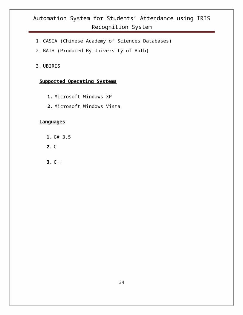
1. CASIA (Chinese Academy of Sciences Databases)
2. BATH (Produced By University of Bath)
3. UBIRIS
Supported Operating Systems
1. Microsoft Windows XP
2. Microsoft Windows Vista
Languages
1. C# 3.5
2. C
3. C++
23

Automation System for Students’ Attendance using IRIS Recognition System
Chapter 6
PROJECT PLANNING
Laying the foundation
24

Automation System for Students’ Attendance using IRIS Recognition System
6.1 Activity Plan
Scheduling
1) Requirement Gathering
Sr. No. Name of Sub module No. of hours From Date To Date
1 Literature Survey 30 18th August, 09 30thAugust, 09
2 Study of Algorithm
(Existing Iris)
48 28th August, 09 15th September, 09
2) Requirement Analysis
Sr. No. Name of Sub module No. of hours From Date To Date
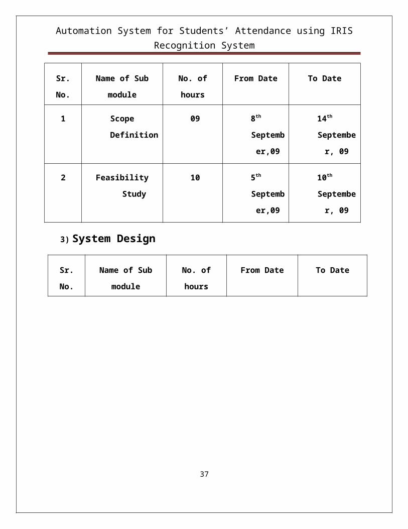
1 Scope Definition 09 8th September,09 14th September, 09
2 Feasibility Study 10 5th September,09 10th September, 09
3) System Design
Sr. No. Name of Sub module No. of hours From Date To Date
25

Automation System for Students’ Attendance using IRIS Recognition System
1 Study of Algorithms 09 19th September, 09 11th October, 09
2 Implementation of
Algorithms
120 18th December, 09 25th January, 10
3 Design of GUI’s 80 12th February,10 28th February,10
4Study of
Connectivity35 1st March,10 8th March,10
5 Testing the system on
different
image format
40 12th March,10 28th March,10
6 Other Aspects 30 15th February, 10 15th March, 10
7 UML Design 09 6th January, 10 30th January, 10
4) Software Testing
26
Automation System for Students’ Attendance using IRIS Recognition System
Chapter 7
DESIGN
Expressing ideas
27

Automation System for Students’ Attendance using IRIS Recognition System
7.1 Design Overview
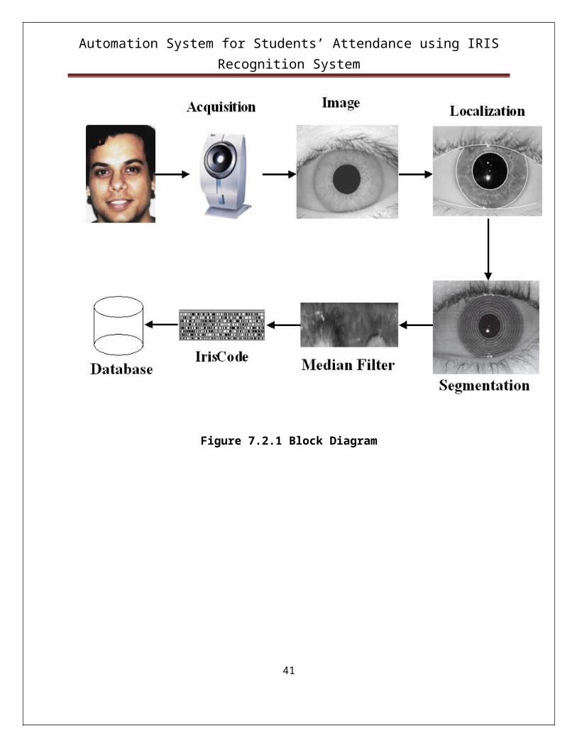
Block Diagram
Figure 7.2.1 Block Diagram
28
Automation System for Students’ Attendance using IRIS Recognition System
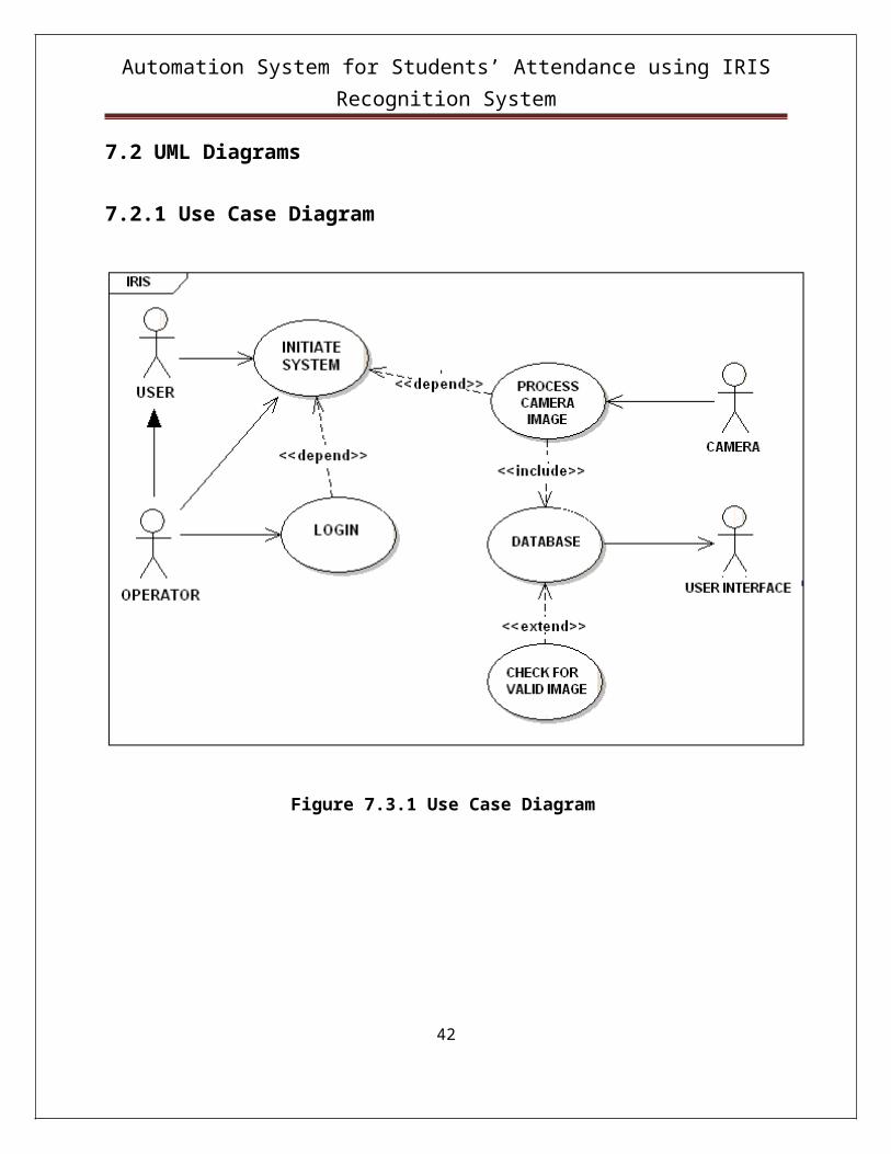
7.2 UML Diagrams
7.2.1 Use Case Diagram
Figure 7.3.1 Use Case Diagram
29

Automation System for Students’ Attendance using IRIS Recognition System
7.2.2 Sequence Diagram
30
Automation System for Students’ Attendance using IRIS Recognition System
Figure 7.3.2 Sequence Diagram
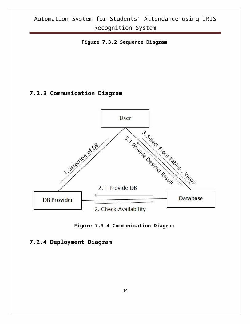
7.2.3 Communication Diagram
31

Automation System for Students’ Attendance using IRIS Recognition System
Figure 7.3.4 Communication Diagram
7.2.4 Deployment Diagram
Figure 7.3.5 Deployment Diagram
32
Automation System for Students’ Attendance using IRIS Recognition System
Chapter 8
HOW SYSTEM WORKS
Way it goes!
8.1 System Overview33
Automation System for Students’ Attendance using IRIS Recognition System
The entire system works just like any other application using navigation controls. The end
user can navigate from one page to another and can view image and other details of the entered
roll number as he wishes. The application spans the following pages in accordance with the end
user selection:
1. Welcome Page
2. Selection of the required task – register/recognition
3. If register is selected
3.1 Fill the details of the student
3.2 Capture his image
3.3 Generate the iris code and store in database
4. If recognition is selected
4.1 Enter the roll number to be verified.
4.2 Capture the image
4.3 Generate the iris code and compare with the database
4.4 If verified – mark the attendance
4.5 Else ask him to register.
5. View the attendance sheet of the whole class.
8.1.1 Registering a student
Initially the database of the students has to be prepared, for this purpose the students have
to register themselves.
34

Automation System for Students’ Attendance using IRIS Recognition System
The steps for registering a student are –
1. Go to Home page Computer Department Register.
2. Fill the details of that student including his Name, Roll number, Year, Branch, Contact
number, Address, E-mail id.
3. Take the eye image of the student with the specified camera.
4. Browse the photo of the student whose information is filled.
5. Press “Create iris”.
6. The iris code will be generated.
7. Press the “Submit” button.
35

Automation System for Students’ Attendance using IRIS Recognition System
Thus the iris code will be generated for the eye image of that student and will be stored with his
personal information.
8.1.2 Recognizing a student
For recognizing a student for marking his attendance –
1. Go to Home page Computer Department Recognition.
2. Enter the roll number of the student you want to recognize.
3. Press “Recognition”.
36
Automation System for Students’ Attendance using IRIS Recognition System
4. The student information will be displayed.
5. Press “Browse” to select the recent image of the student.
6. Press “Create iris”.
7. The iris code will be generated.
8. Press “verify”.
9. According to the, the result will be displayed.
10. If the image is already stored, then is shows “Valid Student. Attendance marked.”
If not, then it asks to “Register”.
37

Automation System for Students’ Attendance using IRIS Recognition System
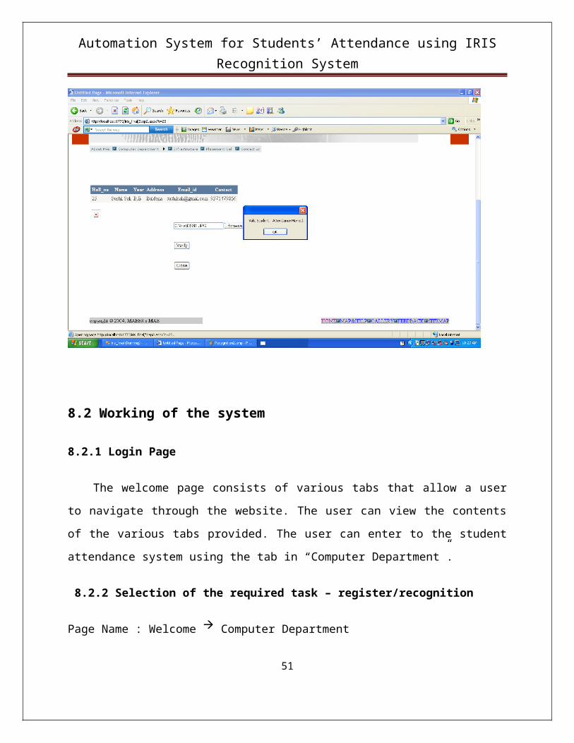
8.2 Working of the system
8.2.1 Login Page
The welcome page consists of various tabs that allow a user to navigate through the
website. The user can view the contents of the various tabs provided. The user can enter to the
student attendance system using the tab in “Computer Department”.
8.2.2 Selection of the required task – register/recognition
Page Name : Welcome Computer Department
Input : Click on Register/ Recognition
Output : Register/Recognition Page
8.2.3 Selecting a proper step:38

Automation System for Students’ Attendance using IRIS Recognition System
8.2.3.1 If register is selected - Fill the details of the student
Page Name: Welcome Computer Department Register
Input : Roll no., Name, Address, Contact, E-mail id, Year.
8.2.3.2 Capture his image
Page Name: Welcome Computer Department Register
Input : Eye image.
Output : Register New User window appears.
8.2.3.3 Generate the iris code and store in database
Page Name: Welcome Computer Department Register
Input : Click on Register
Output : Iris code is generated and information is stored in the database.
8.2.4 Reselection of Step1
8.2.4.1 If recognition is selected - Enter the roll number to be verified.
Page Name: Welcome Computer Department Register
Input : Button click to select recognition of the specified roll number.
Output : Page with details of the student.
8.2.4.2 Capture the image
39

Automation System for Students’ Attendance using IRIS Recognition System
Capture the image of the student using the digital camera as specified.
8.2.4.3 Generate the iris code and compare with the database
Page Name: Welcome Computer Department Recognition
Input : Select on the current image taken and click ok.
Output : Iris code for the new image is generated and is compared with the database.
8.2.4.4 If verified – mark the attendance
Page Name: Welcome Computer Department Recognition
Input : Image for recognition.
Output : Verified and attendance marked.
8.2.4.5 Else ask him to register.
Page Name: Welcome Computer Department Recognition
Input : Image for recognition.
Output : Not verified. Register if not present in the database.
8.2.5 View the attendance sheet of the whole class.
Page Name: Welcome Computer Department Recognition Attendance Sheet
Input : Click on Welcome Computer Department Recognition Attendance Sheet
Output : Attendance Sheet for whole class is appearing.
8.3 Source code Modules:
40
Automation System for Students’ Attendance using IRIS Recognition System
I) Segmentation
/* Function name : segment_image()
input : 13*13 block of the input image in an array form
output : The entire block flagged to be used for further
calculations or left to be neglected further.
*/
void segment_image()
{
int i=0,j=0,x=0,y=0,avg=0,count=0;
for(i=0;i<BLOCKS;i++)
for(j=0;j<BLOCKS;j++)
{
avg=0;
count=0;
for(x=(i*WIN);x<(i*WIN)+WIN;x++)
for(y=(j*WIN);y<(j*WIN)+WIN;y++)
avg=image[x][y]+avg;
avg=avg/(WIN*WIN);
41
Automation System for Students’ Attendance using IRIS Recognition System
for(x=(i*WIN);x<(i*WIN)+WIN;x++)
for(y=(j*WIN);y<(j*WIN)+WIN;y++)
{
if((image[x][y]>(avg-10))&&(image[x][y]<(avg+10)))
count++;
}
if(count>121)
{
for(x=(i*WIN);x<(i*WIN)+WIN;x++)
for(y=(j*WIN);y<(j*WIN)+WIN;y++)
image[x][y]=255;
}
}
}
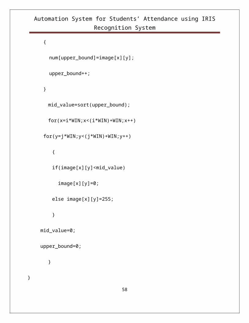
II) Binarise Image
/* Function name : binarise_image
input : 13*13 block of the image array
42

Automation System for Students’ Attendance using IRIS Recognition System
Description : Each pixel is either marked as 0 or 255 depending upon
its intensity
output : 13*13 array with each value either as 0 or 255
*/
void binarise_image()
{
int i=0,j=0,x=0,y=0,mid_value=0,upper_bound=0;
for(i=0;i<BLOCKS;i++)
for(j=0;j<BLOCKS;j++)
{
for(x=i*WIN;x<(i*WIN)+WIN;x++)
for(y=j*WIN;y<(j*WIN)+WIN;y++)
{
num[upper_bound]=image[x][y];
upper_bound++;
}
mid_value=sort(upper_bound);
for(x=i*WIN;x<(i*WIN)+WIN;x++)
43
Automation System for Students’ Attendance using IRIS Recognition System
for(y=j*WIN;y<(j*WIN)+WIN;y++)
{
if(image[x][y]<mid_value)
image[x][y]=0;
else image[x][y]=255;
}
mid_value=0;
upper_bound=0;
}
}
III) Median Filter
/* Function name : median_filter()
input : 13 * 13 block array of the input image array
output : 13 * 13 block array with noise eliminated using median filtering
*/
void median_filter()
{
44

Automation System for Students’ Attendance using IRIS Recognition System
int x=0,y=0,mid_value=0,upper_bound=0;
for(x=1;x<300;x++)
for(y=1;y<300;y++)
{
upper_bound=0;
num[upper_bound]=image[x-1][y-1];
num[upper_bound++]=image[x-1][y];
num[upper_bound++]=image[x-1][y+1];
num[upper_bound++]=image[x][y-1];
num[upper_bound++]=image[x][y];
num[upper_bound++]=image[x][y+1];
num[upper_bound++]=image[x+1][y-1];
num[upper_bound++]=image[x+1][y];
num[upper_bound++]=image[x+1][y+1];
upper_bound++;
mid_value=sort(upper_bound);
image[x][y]=mid_value;
}
45

Automation System for Students’ Attendance using IRIS Recognition System
}
46

Automation System for Students’ Attendance using IRIS Recognition System
Chapter 9
TESTING
Learning from mistakes
47

Automation System for Students’ Attendance using IRIS Recognition System
9.1 Software Testing
Software Testing is an empirical investigation conducted to provide stakeholders with
information about the quality of the product or service under test, with respect to the context in
which it is intended to operate. This includes, but is not limited to, the process of executing a
program or application with the intent of finding software bugs. It can also be stated as the process
of validating and verifying that a software program/application/product meets the business and
technical requirements that guided its design and development, so that it works as expected and
can be implemented with the same characteristics.
9.2 Testing artifacts
Software testing process can produce several artifacts
Test case
A test case in software engineering normally consists of a unique identifier, requirement
references from a design specification, preconditions, events, a series of steps (also known as
actions) to follow, input, output, expected result, and actual result. Clinically defined a test case
is an input and an expected result. This can be as pragmatic as 'for condition x your derived
result is y', whereas other test cases described in more detail the input scenario and what results
might be expected.
Test script
The test script is the combination of a test case, test procedure, and test data. Initially the
term was derived from the product of work created by automated regression test tools. Today,
test scripts can be manual, automated, or a combination of both.
Test data
The most common test manually or in automation is retesting and regression testing. In
most cases, multiple sets of values or data are used to test the same functionality of a particular
feature. All the test values and changeable environmental components are collected in separate
48

Automation System for Students’ Attendance using IRIS Recognition System
files and stored as test data. It is also useful to provide this data to the client and with the product
or a project.
Test suite
The most common term for a collection of test cases is a test suite. The test suite often also
contains more detailed instructions or goals for each collection of test cases. It definitely contains
a section where the tester identifies the system configuration used during testing. A group of test
cases may also contain prerequisite states or steps, and descriptions of the following tests.
Test plan
A test specification is called a test plan. The developers are well aware what test plans will
be executed and this information is made available to the developers. This makes the developers
more cautious when developing their code. This ensures that the developer’s code is not passed
through any surprise test case or test plans.
Test harness
The software, tools, samples of data input and output, and configurations are all referred to
collectively as a test harness.
49

Automation System for Students’ Attendance using IRIS Recognition System
9.3 System put to Test
9.3.1 Testing Snapshots
Figure 9.3.1.1 Test Cases.
50
Automation System for Students’ Attendance using IRIS Recognition System
Figure 9.3.1.2 Run Test.
51

Automation System for Students’ Attendance using IRIS Recognition System
Figure 9.3.1.3 Validation Test.
52

Automation System for Students’ Attendance using IRIS Recognition System
9.3.2 Testing Report
Subject1 Browsing through the website1.1 Authentication
Subject: LoginStatus: DesignDesigner: adminCreation Date: 20/04/10Type: MANUAL
1.1.1 StepsStep Name Description Expected ResultStep 1 Browsing through the web
pages.When the web site name is given in the address bar the home page is opened.
Step 2 Clicking on About MAE tab. When clicked on "About MAE" Tab home page is displayed.
Step 3 Clicking on Infrastructure tab. When clicked on " Infrastructure" Tab Infrastructure page is opened.
Step 4 Clicking on Placement Cell tab.
When clicked on " Placement Cell" Tab Placement Cell page is opened.
Step 5 Clicking on Contact Us tab. When clicked on " Contact Us" Tab Contact Us page is opened.
Step 6 Clicking on Computer department
When clicked on " Computer department" Tab Two sub parts are opened.
Step 7 Check the feed back in the web page.
Feed back is accepted in the web page.
53

Automation System for Students’ Attendance using IRIS Recognition System
1.2 Register New StudentSubject: LoginStatus: DesignDesigner: adminCreation Date: 20/04/10Type: MANUAL
1.2.1 StepsStep Name Description Expected ResultStep 1 Entering Roll Number of
student.Only numbers are accepted, characters are not allowed.
Step 2 Entering Name of student. Characters are allowed.Step 3 Entering E-mail id of student. Only the E-mail ids accrding
to DNS system are accepted otherwise displays the error msg.
Step 4 Entering Address of student . The address of the student is accepted.
Step 5 Entering Contact no of the student.
Only Numbers can be entered.
2 Schema Details2.1 Procedures
Subject: SchemaDetailsStatus: DesignDesigner: adminCreation Date: 20/04/10Type: MANUAL
2.1.1 StepsStep Name Description Expected ResultStep 1 Press browse in the
registration web page.The dialog box for choosing the image is displayed.
Step 2 Select particular eye image of the respective student.
The eye image is displayed.
Step 3 Press create iris code. The processing of selected eye image takes place and iris code is generated.
Step 4 Press submit. The generated iris code along with the entered information of the student is inserted into the database.
54

Automation System for Students’ Attendance using IRIS Recognition System
2.2 Recognition of a studentSubject: SchemaDetailsStatus: DesignDesigner: adminCreation Date: 20/04/10Type: MANUAL
2.3.1 StepsStep Name Description Expected ResultStep 1 Enter the Roll number to be
recognised and pressed recognise.
The entered information of the give roll number is displayed.
Step 2 Press Browse. The dialog box for selecting a particular eye image is displayed.
Step 3 Press Verify. The iris code for the newly given eye image is generated and compared with the already existing entries.
2.3 View the total attendanceSubject: SchemaDetailsStatus: DesignDesigner: adminCreation Date: 20/04/10Type: MANUAL
2.3.1 StepsStep Name Description Expected ResultStep 1 Test the database. database is opened and
attendance sheet is displayed.Step 2 View the present status of the
student.Present Status of the student is displayed.
55

Automation System for Students’ Attendance using IRIS Recognition System
Chapter 10
CONCLUSION
Leap towards the new beginning
56

Automation System for Students’ Attendance using IRIS Recognition System
The system for attendance management works efficiently for various types of image such
as .bmp, .jpeg, and other formats. This system is also built up to show the total attendance of the
students. As a website, this system can be uploaded on the internet and can be viewed as a website.
Thus, in total this system can be described as-
Automated – As it successfully monitors the attendance.
Secured – Built in ASP.Net makes it secured website.
Flexible – As it can run on different image format.
Quick – As the response time of the system is very less.
57
Automation System for Students’ Attendance using IRIS Recognition System
Chapter 11
FUTURE SCOPE
Thinking out of the box
58

Automation System for Students’ Attendance using IRIS Recognition System
We have worked sufficiently on still images for iris recognition of a person and
applied it for managing the attendance. This concept of iris recognition for still images can be
further extended to -
1. Iris recognition using a real time video.
2. Built a complete product to make it as fully fledged software.
3. The developed application should be able to support a large database.
4. The response time for the system supporting large database should be very less.
At last, the unique biometric identification technique of IRIS recognition should
be applicable to a variety of real time systems for Verification, Identification, Security and
Safety purposes.
59