Embed Size (px)
Citation preview

Automotive Approaches Automotive Approaches
For For
General Aviation Aircraft General Aviation Aircraft
David M. Grieco David M. Grieco Munro and Associates Munro and Associates 1749 Northwood Drive 1749 Northwood Drive Troy, Michigan 48084 Troy, Michigan 48084
248 362 5110 248 362 5110 [email protected]@munroassoc.com

Table Of Contents
Executive Summary………………………………………………… 3 Purpose……………………………………………………………………...3 Background………………………………………………………………….3 Principal Findings…………………………………………………………..4 Recommendations…………………………………………………………8 Approach…………………………………………………………………….8
Munro & Associates…………………………………………………13
The Lean Engineering Approach ………………………………….15 Developing Requirements……………………………………………… ...16 Six Sigma……………………………………………………………………20 Lean Design™……………………………………………………………...26 Supply Chain………………………………………………………………..34 Modularity…………………………………………………………………...38 Lean Software Development……………………………………………...42
Digital Technology Migration to General Aviation…………….49 Auto Technology; The Digital Car………………………………..53
42 Volt Systems……………………………………………………………53 Drive By Wire Technologies……………………………………………...54 Night Vision………………………………………………………………...55 Vehicle Electrical System Architecture………………………………….56 Telematics……………………………………………………………….…58 Safety Systems Technology……………………………………………..59
Automotive Approaches for Aircraft Systems…………………61 Vehicle Architecture Development……………………………………….61 Automotive Example of Modular Architecture…………………………..64 Summary of Interior Systems Automotive Approaches………………..69 Spaceframe Structure Development……………………………………..71 Summary of Structural Automotive Approaches…………………….….75
Economic Analysis………………………………………………….77 Conclusions…………………………………………………………..82 Glossary……………………………………………………………………….….83 Other Contributors………………………………………………….103 Sources and Methods………………………………………………113
2

Executive Summary Purpose Within NASA Aeronautics’ Three Pillars Strategy for General Aviation Revitalization lies the challenge of delivering up to 20,000 aircraft deliveries in 20 years. This must be accomplished in an environment of decreasing aircraft price/cost of ownership, increasing ease of use, increasing performance, and increasing safety. To help NASA realize these goals Munro and Associates was commissioned to demonstrate that automotive style systems integration for “Six-Sigma” quality, Lean Design™ and lean manufacturing technologies can radically reduce vehicle complexity, while revolutionizing safety, efficiency, and affordability of SATS aircraft. Munro & Associates submits that NASA – SATS management needs to institutionalize Lean Thinking to enable these changes to happen. The purpose of this report is to discuss how General Aviation (GA) can achieve the Automotive Cost Paradigm through application of Lean Thinking and automotive style product integration methodologies. This reports establishes a high level baseline for the methodology and design approach required to support this hypothesis. It also forecasts the potential range of economic opportunities that are feasible using an automotive cost paradigm for manufacturing of 21st century jet personal air vehicles that travel up to 6 times the speed of a car at twice the direct operating cost.
Automotive Cost Paradigm
• Aircraft can be designed and manufactured at unit costs ~ 2 X that of automobiles.
• Customer convenience technologies developed for automobiles can be
transferred to GA Aircraft.
• Cockpit architectures can share common design standards between automobiles and GA Aircraft.
• Information delivery architectures can be shared between automobiles and
GA Aircraft. Background Transportation in the U.S., long the underpinning of economic strength, is losing speed, accessibility, flexibility, and efficiency. This nation’s investments to reduce highway and hub-and-spoke congestion and delays are reaching the point of diminishing returns, and transportation demand continues to soar. As time becomes the “scarce commodity” of the information age, demand for aviation transportation will outpace the capacity provided by the system of today’s hub-and-spoke airports. Thus, early in the 21st century, when speed is at a premium, the nation’s doorstep-to-destination travel speeds will be in decline. Delays in the hub-and-spoke and aging highway systems may limit economic expansion in the information age to fewer well-connected regions and communities. Fortunately, most of the
3

U.S. population lives within a 30-minute drive of over 5,000 public-use landing facilities. This infrastructure is an untapped national resource for mobility. If full broad utilization of the GA infrastructure is going to happen, the GA Industry will most certainly have to transition into a mass production mode. Today GA companies and production shops operate under a low volume manual assembly model. For example the Mooney Aircraft Corporation’s M-2 or Ovation Model sells for approximately $429,000. In the 1980’s it took 4300 hours to build an airplane, and the company lost $33 million in 10 years. In 1997, new management restructured the company and reduced the build to 2900 hours and made other moderate improvements to the operation. They found that the production flow moved airplanes and materials around needlessly. At an annual production volume of 100 planes, it took 37 days to build an airplane, improvements ultimately reduced it to 21. Ninety eight percent of all parts were made in house. There was no make versus buy policy, a policy was implemented. The rework and repair rate was a costly 38 percent and improved to 36 percent. There was $20 million in material inventory, it was reduced to $11 million. Total employees were slimmed down from 630 to 318. In spite of these improvements the Mooney Aircraft Corporation recently announced bankruptcy. It is reasonable to conclude from this small amount of information that the improvements made were insufficient to insure Mooney’s ongoing commercial viability. Furthermore, lean manufacturing was really never achieved, nor could it be achieved unless a lean aircraft design was first implemented. Principal Findings With the luxury of competition, the automotive industry has learned the importance of Lean Design™ and how it is an enabler for lean manufacturing. The key lesson learned is that product design, which accounts for only 5% of a product’s total cost, actually dictates 70% of the products total manufacturing cost and 90% of it’s life cycle cost. In the Japanese lean manufacturing oriented auto industry it takes 16 man-hours to build a high technology four seat car. Lean American auto OEMs such as Daimler Chrysler, can annually build 300,000 highly contented minivans for an average of 18 man-hours of assembly direct labor per vehicle and sell each at a average price of $20,000. The same company can also build a low volume sophisticated sports car, the Prowler, at a fraction of the minivan annual volume, 3,000 units, using approximately 2 times the direct assembly labor of the minivan, or 34 hours and sell them for $45,000. The question is, how can DCX build the Prowler at 100 times less the volume for only twice the cost? How do they do that? At a vehicle system level; the instrument panel and avionics on the same GA light aircraft weighs 200lbs and costs $40,000. A highly contented modular auto IP, complete with gages, instrumentation and entertainment hardware, for a luxury vehicle is purchased by an OEM from a Tier One supplier at a cost of approximately $1,000 and 100 lbs. Current and near future integrated glass cockpit offerings from the major avionics manufactures lack a uniting foundation. Avionic manufactures add on stand-alone fixes and technology boxes to share limited information with a few other products. This approach results in limited increased functionality and does so at the expense of increased complexity and cost. This is not in the spirit of AGATE & SATS.
4

Their vision is achievable through integration of AGATE, SATS & automotive technologies combined with current computer industry open architecture standards. Thus a new 21st century enabling platform can be developed which will increase cockpit functionality while decreasing pilot workload at a fraction of the cost of today’s systems. By leveraging the advanced computing technology that will go into mass production in cars in the next few years and incorporating such components with commercial X-Box type hardware systems, off-the-shelf displays and web enabled sensors. The cockpit systems for small airplanes and helicopters in the near future will be lighter, more reliable, less costly and more capable than even the most complex avionics flying today. Certain automotive Tier 1 suppliers, such as Delphi and Visteon are in a good position to provide telematics products to more than just the auto industry, because they are very good vehicle and systems engineers. They know what it takes to harden those systems and make them reliable enough for the extremes of the vehicle environment.
Interactive Intelligent Vehicle Capability Compatibility With SATS Enabling Technologies
Digital Vehicle Capability
High Density
Ops
Virtual Visual Meteor
Conditions Navigation and Route
Guidance Software Enabled Control
Automation Collision Notification
Conflict Detection and
Avoidance
Entertainment/Communications Airborne Internet Mobile Internet Services Airborne Internet
In Vehicle Computing and Diagnostics
Integrated Information and Decision Support System
Collision Warning/Avoidance Conflict Detection and Avoidance
Vision Enhancement Integrated Information and Decision Support System
Adaptive Cruise Control Self Separation Driver Condition Monitoring VIFR
Obstacle Detection Conflict Detection and Avoidance
Vehicle Stability Integrated Information and Decision Support System
5
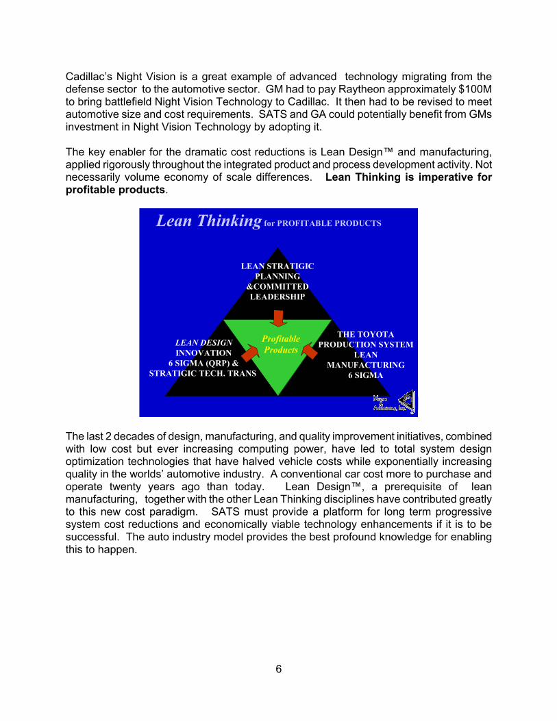
Cadillac’s Night Vision is a great example of advanced technology migrating from the defense sector to the automotive sector. GM had to pay Raytheon approximately $100M to bring battlefield Night Vision Technology to Cadillac. It then had to be revised to meet automotive size and cost requirements. SATS and GA could potentially benefit from GMs investment in Night Vision Technology by adopting it. The key enabler for the dramatic cost reductions is Lean Design™ and manufacturing, applied rigorously throughout the integrated product and process development activity. Not necessarily volume economy of scale differences. Lean Thinking is imperative for profitable products.
Shahid
LEAN STRATIGIC PLANNING
&COMMITTED LEADERSHIP
LEAN DESIGNINNOVATION
6 SIGMA (QRP) &STRATIGIC TECH. TRANS.
THE TOYOTA PRODUCTION SYSTEM
LEAN MANUFACTURING
6 SIGMA
ProfitableProducts
Lean Thinking for PROFITABLE PRODUCTS
The last 2 decades of design, manufacturing, and quality improvement initiatives, combined with low cost but ever increasing computing power, have led to total system design optimization technologies that have halved vehicle costs while exponentially increasing quality in the worlds’ automotive industry. A conventional car cost more to purchase and operate twenty years ago than today. Lean Design™, a prerequisite of lean manufacturing, together with the other Lean Thinking disciplines have contributed greatly to this new cost paradigm. SATS must provide a platform for long term progressive system cost reductions and economically viable technology enhancements if it is to be successful. The auto industry model provides the best profound knowledge for enabling this to happen.
6

Noting the huge profit opportunity lying hidden in the aircraft industry, as illustrated above, the Japanese through their lean approaches will insure the commercial viability of their entry into this market. In February 1999 the giant, Toyota announced it was evaluating a business case for a four seat light Toyota aircraft. Recently, Honda, which had long been developing turbo fan engines, rented hangar space in North Carolina to develop a small business jet. For the United States to maintain leadership in this market and attract new customers, aviation products must be modernized with a focus on safety, low cost, ease of use, and comfort. The challenge of foreign competition has made such an effort imperative. In response to this, the General Aviation Propulsion Program (GAP) is a great example of a successful government industry collaborative effort with objectives focused and funding tied to developing hardware for a commercial product. The industry participants, Williams and Teledyne Continental Motors, were challenged to investigate better methods for developing and manufacturing and maintaining new engines at lower costs. To achieve this, they designed the engines ( turbofan FJX-2, and a jet fueled diesel) for mass production. This was made possible by reducing the number of parts in the engines – Lean Design. Using a derivative of FJX-2, the all new Eclipse 500 business jet is now in the process of certification. The GAP model should be used a model for success by SATS and other similar NASA projects. All these efforts will make incremental contributions to the next generation of GA. The issue of what comes next after these projects are commercialized, needs to be addressed. The answer lies in part with NASA, the domestic GA Industry and the global automotive industry.
7

Recommendations “I can’t believe it! Foreigners have stolen half our market share by selling their products at 30% less cost with three times our Quality! What are we going to do about this?”
Henry Ford II Speech, circa 1979 What Ford, Chrysler and others did in response to foreign competition is what the Aircraft industry can do; design a product that has better quality, easier assembly, lower cost, and of course, more PROFIT. This process doesn’t involve accounting tricks, layoffs, kickbacks, sophisticated automation or out - sourcing, all you need are the tools, the team, the talent and the time. SATS management should:
• Learn more about components of Lean Thinking • Adopt and require appropriate participants to institutionalize Lean Thinking
based on project needs • Develop and pursue automotive technologies, methods and supply chain alliance
strategies • Focus objectives and funding on developing hardware and software for
commercialization Approach Developing Requirements Successful product development depends on understanding the wants and needs of a given enterprise’s internal and external customers. The leading cause of new product failure is missing or poorly defined customer requirements. A robust integrated product development activity understands the primacy of the customer. The linkages between product and customer are clearly understood and defined. Companies with exemplary integrated product development activities all possess 3 common practices for building the customer into the process:
• A clear methodology for developing product definitions, based on how well user wants and needs are understood, risks are assessed and regulations considered.
• Consistent and effective application of a variety of methods for capturing the voice of the customer.
• A superior value proposition which delivers a competitive advantage is developed and internalized before the product is designed
Six Sigma Deployment Munro & Associates’ Six Sigma deployment strategy emphasizes the direct correlation between customer satisfaction, waste, operating cost, and the number of product defects.
8

To this end, the Six Sigma statistic measures the capability of a given process to perform virtually defect-free work Typical products and services are routinely found with a quality performance level of 4 sigma. This results in 25% of each sales dollar being spent on correcting defects. The best commercial aircraft manufacturing industry average is estimated to be between 3 and 3.2 Sigma. Benchmarking data indicates that many “world class” products and services have a performance level of 6 sigma, or where approximately 1% of gross revenues or less is spent on maintaining near perfect performance. Lean Design™ What is Lean Design™ Lean Design™ encompasses a set of methods and principles that ultimately result in a product design that is elegantly simple: it looks good, performs well, and can be manufactured easily with quality at a profit. A Lean Design™ will have a minimum number of parts and process steps to achieve all of the customer requirements. How are Lean Design™ and Robust Design related? Since a true Lean Design™ will be easy to manufacture, it will also be robust in regard to considerations of process capabilities. Additionally, a Lean Design™ provides an opportunity to achieve a robust design with much less effort, since fewer parts and process steps will require consideration. The guiding philosophy is one of progressive refinement in an environment of simultaneous product and manufacturing process development. At the end of each iteration, design information is disseminated to all the other related vehicle systems engineering teams, which then execute their own local design studies in preparation for the start of the next iteration. The ability to influence the product design is greatest in the early stages of a designs development. This ability is diminished as the design moves closer to production. Consequently the initial studies are often the key to the ultimate success or failure of the design. The net effect of this active iteration approach is to reduce design time, produce a design that is in compliance to a given set of criteria and the efficient allocation of engineering resources. By the time the concept is defined, about 70% of the life cycle cost is already committed, and by the time of completion of a preliminary detailed design the figure rises to 85 %. Yet at that time, only 5% of the total project cost has been expended. It is very clear that what happens in the earliest, formative stages of the design has enormous leverage. The message is that designers must be extremely sound in their early decisions. The only way to insure good decisions at this stage however is through the use of cross-functional design teams. This has been a common practice in the auto industry for over 20 years. The best way to minimize the number of design changes over the course of a project is through the Lean Design™ process. The key success factors for Lean Design™ are:
9
1. Do it early 2. Use cross-functional teams 3. Use an iterative and structured methodology 4. Be Creative
Ultimately, an active iteration design process focuses information where and when it is most needed, and where it can be applied the most effectively. Iterations also provide natural milestones by which to gage progress as well as clear transitions from one level of detail to the next. Using the Lean Design™ Process will most probably increase preliminary design time by 15% when compared with the traditional process. However, because of the net reduction in the quantity of design changes the over all design process impact is a 45% overall time savings.
Why iterate?
• Complex interaction of vehicle sub-systems • Incomplete vehicle design information • Inability to fully predict design behavior
A prerequisite to achieve lean manufacturing involves the carefully coordinated interaction of product designers and manufacturing personnel to determine the best initial approach for the design. To achieve a world-class product in any industry, designers must give careful consideration to the inherent variation of manufacturing processes before committing to a design configuration. Trade-offs will be necessary. Some processes need to be completely avoided. Process capabilities must be known before establishing part shapes, sizes, tolerances, and assembly requirements. New technologies must be characterized for initial and potential process capability before final decisions are made. Lean Design™ encompasses a set of methods and principles that ultimately result in a product design that is elegantly simple; it looks good, performs well, and can be manufactured easily with Quality at a profit. A Lean Design™ will have a minimum number of parts and process steps to achieve all of the customer requirements. Since a true lean design will be easy to manufacture, it will also be robust in regard to considerations of process capabilities. Additionally, a lean design provides an opportunity to achieve a robust design with much less effort, since fewer parts and process steps will require engineering.
10

•• 80% fewer parts80% fewer parts
•• 66% fewer suppliers66% fewer suppliers
•• 83% less assembly time83% less assembly time
•• 44% lower total cost44% lower total cost
•• 50% less time to repair50% less time to repair
•• More reliableMore reliable
•• 60 second assembly…. 60 second assembly….
blindfolded!blindfolded!•• More screws in old design than More screws in old design than
total parts in new design!total parts in new design!
Associates,Inc.&
M unro VALUE
QUALITY
PR
OFIT
Associates,Inc.
&M unro VALUE
QUALITY
PR
OFIT
What are the results What are the results of of Lean DesignLean Design™™??
The Supply Chain Auto suppliers at all levels may consider aviation work if there is a mid to long term opportunity to make a reasonable return on their investment. Some in fact are already supplying aircraft OEM’s with mockups and production parts. Profits would come from; licensing of technology , component sales to GA OEMs and suppliers, added volume at higher profit margins. Since an individual GA OEM may not have enough volume to interest an automotive supplier, GA OEMs should consider collaborating with a focus on developing standard components that could be used across all OEMs. Consideration should be given to components that are transparent to the aircraft purchaser, such as propulsion, structural, electrical systems etc. Participants will benefit from potentially huge cost savings and the creation of de facto standards that all OEMs will want to adopt. OEMs are then free to compete based on appearance, performance and price. This approach is commonly used by the auto industry, a recent example is the move to 42 Volt vehicle electrical systems, which will be discussed later in this report. Another opportunity is for a GA OEM to work with a willing automotive Tier Two, Three or beyond to have components developed, certified and produced. Many automotive suppliers who have in house design capability also have low volume build capabilities by way of their mockup and prototyping operations. This successful strategy is currently gaining momentum as GA OEM’s are benefiting from significant material cost reductions through using an auto supply chain. Modularity To date, virtually all automotive modular applications have been tactical rather than strategic. There has been little fundamental change in core automotive product architecture where modularity has been tried. If SATS is going to consider modularity, it should be as a strategy, applied rigorously and prudently.
11

A Modular Strategy should comprehend:
• Planning and investing for flexibility o OEMs and suppliers jointly identifying needs and opportunities o OEMs accepting flexibility investments in price negotiations o Technology enhancements o Product development
Problem solving Opportunity identification
o Manufacturing Derivative mix Production volume
o Distribution and marketing requirements Success in modularity depends strongly on maintaining a good working relationship between OEMs and suppliers. Consider the Daimler Chrysler supply chain model, “Extended Enterprise” may be an enabling strategy for SATS modularity. The Extended Enterprise is a goal driven process that unifies and extends the business relationships of suppliers and supplier tiers in order to reduce cycle time, minimize system costs and achieve prefect quality. Lean Software Development The SATS Operating Capabilities of High Density Ops (HDO) and Virtual Visual Meteorological Conditions (VVMC) depends on the development of algorithms and software for success. Lean Production and Total Quality Management (TQM), the paradigm shift management tools that revolutionized manufacturing businesses in the 1980s, can also be applied to software development with the same dramatic results. Lean Production, which evolved from Taiichi Ohno’s efficient system for creating high quality automobiles (the Toyota Production System) is based on the absolute elimination of waste, in both product and process. His system, together with W. Edward Deming’s teachings on quality management teaches managers how to empower workers to investigate problems and systematically improve business processes. The TQM movement emphasizes a culture of continuous improvement of both product and process. The basic practices of these 2 systems can be summed up in the following points: Fundamentals of Lean Production
1. Eliminate Waste 2. Minimize Inventory 3. Maximize Flow 4. Pull From Demand 5. Meet Customer Requirements 6. Do It Right The First Time 7. Empower Workers 8. Ban Local Optimization 9. Partner With Suppliers 10. Create A Culture of Continuous Improvement
12

These fundamentals also adapted to logistics, customer service, healthcare, and finance have made huge impacts on American productivity.
Who Is Munro & Associates, Inc. MISSION Our mission is to help manufacturers transform their organizations to achieve and sustain long-term success through the implementation of a true concurrent engineering strategy. Simply put, our goal is to help manufacturers consistently maximize product value, quality and profit. Since product design influences more than 70 percent of a product’s total cost, a well-defined and executed concurrent engineering strategy can generate dramatic reductions – often as much as 60 percent – in production costs and development time . . . while boosting product reliability and quality. ROLE Working in partnership with our clients, Team Munro helps manufacturers break the industry and corporate paradigms . . . to generate true creativity and real breakthroughs that can propel companies far ahead of their competition. We help companies to eliminate outdated rules, waste and variation – to create an environment which fosters and harnesses the incredible power that lies largely unused: the creativity of employees. We also help introduce companies to new technologies, processes and approaches from other industry segments that can generate breakthrough results. And we help clients to put the right disciplines, approaches, and organizations into place – to help ensure continuing, repetitive success. STRATEGIC SERVICES While Team Munro is among the top consultants specializing in the implementation of Design for Manufacturing principles, our offering is much broader than that. Through our unique Design Prophet™ methodology – which uses a number of tools to help companies view their product’s total life cycle – we help clients to predict, quantify and eliminate obstacles and waste upfront at the earliest design stages. Our offering bridges the strategic and the tactical levels, including:
• Executive product planning assistance • Executive/Engineering management paradigm presentations • Long-term implementation assistance for DFA/DFM principles • Fundamental business practice/focus consulting • Defense Industry Commercialization assistance • Product development organizational restructuring • Cradle to grave product feasibility studies • General management consulting
13

• DFA / DFM / DFS / DFE workshops and training • Value-analysis/Value –engineering assistance • Munro Quality Report Card™ analysis • Competitive product/process benchmarking and Pugh analysis • Manufacturing ergonomics, methods and plant layout evaluation • Product design and redesign services • Project management
EXPERIENCE Since 1988, Team Munro’s multi-disciplined approach has helped manufacturers of all sizes, production volumes and industry segments. Our team of experienced senior consultants – all full-time professionals – brings more than 200 years of profound, detailed knowledge and perspective spanning a broad range of technical areas including DFA / DFM, quality, serviceability, recyclability, engineering software, plastics design, manufacturing engineering, tooling design, robotics, machining and ergonomics. In addition, our associates provide extensive experience in senior management, organizational and operational areas. Team Munro doesn’t just offer a new tool or the next management fad. We bring the best practices and experiences from across all industries and actually help our clients to think and act differently to ensure a competitive advantage. INDUSTRIES SERVED Team Munro has helped clients in virtually every industry segment, size and production-volume range. These industries include: Aerospace Appliances Automotive Aviation Computers Consumer products Defense Electronics
Industrial equipment Jigs and fixtures Machine tools Mail/postal systems Medical products Off-highway equipment Printing/Copying equipment Toys
RESULTS
With Team Munro’s assistance, scores of manufacturers around the world from a wide variety of industries have saved more than $9 billion and have retained more than 50,000 jobs since 1988.
14

Among the real-world results our clients have enjoyed are:
• Dramatically shortened product development cycles • Significantly reduced manufacturing costs • Fewer assembly and manufacturing operations • Reduced assembly labor and improved assembly ergonomics • Elimination of expensive shop-floor changes and re-work • Less paperwork, capital investment and overhead • Improved creativity, communication and teamwork among employees • Enhanced product quality, reliability and customer loyalty • Reduced parts handling, inventory and warehouse space • More effective product development activities
Lean Engineering Approach When the times demanded, America designed highly producible aircraft and created simple systems to build them. Boeing did it one-way; Ford did it another. Both achieved the desired result -- huge volumes of quality aircraft. We can still learn from what our grandparents did.
From concept to shutdown, B-24 production at Willow Run, Michigan was high drama. Before WWII, when the nation was planning for war production, Ford was recognized for tool making and machine design, so the government wanted Ford to build tools and aircraft parts. Ford would have none of that. Production of the B-24 by automotive methods became a personal challenge to Charlie Sorenson, Ford’s President and the visionary of both the modular redesign of the B-24 and of production flow at Willow Run. In January 1941, before ground was to be broken in April for the Willow Run plant, Charlie, Easel Ford, and a group of Ford engineers visited the Consolidated plant in
15

San Diego to see the B-24 for the first time. They were not impressed. As built configurations of planes were being “engineered together” six months ahead of the drawings, and the design was a bundle of parts. Nothing could be massed produced with such a system. Consolidated engineers thought they could get a plane a week out; one a day when they got rolling. But Sorenson instantly knew that unless the design was formalized, stable, and modular, a flow of production would be only a pipe dream. On the night of January 8, 1941, Sorenson took rolls of B-24 drawings to his hotel room. More than anyone else he had converted Henry Ford’s design ideas and assembly line vision for the model T to reality. On subsequent Ford models he simplified designs and built tools and machines that would feed the moving assembly line. Now he called on all his experience for a grander vision. Sorenson stayed up all night, sketching and calculating. By morning he had mapped out how to break the B-24 into major modules, then sub-modules, then, the equipment that would feed a mile long assembly line. The next day, Sorenson told both Consolidated and the government that Ford would either build a complete B-24 at the rate of one per hour, or they would build nothing. The plan was set for Willow Run, 3 months before ground was broken. Sorenson and his engineers redesigned the B-24, designed and built its tooling and assembly equipment, constructed the plant, hired and trained the people, and had it operational by September 1942, 18 months after groundbreaking. As it turned out, Sorenson’s engineering judgment was remarkably sound; he stated, “ Unless you can see a thing, you cannot simplify it. And unless you can simplify it, it’s a good sign you can’t make it.” Developing Requirements Successful product development depends on understanding the customer wants and needs of a given enterprise’s internal and external customers. The leading cause of new product failure is missing or poorly defined customer requirements. A robust integrated product development activity understands the primacy of the customer. The linkages between product and customer are clearly understood and defined. Companies with exemplary integrated product development activities all possess 3 common practices for building the customer into the process:
• A clear methodology for developing product definitions, based on how well user wants and needs are understood, risks are assessed and regulations considered.
• Consistent and effective application of a variety of methods for capturing the voice of the customer.
• A superior value proposition which delivers a competitive advantage is developed and internalized before the product is designed.
16
In the automotive industry, these wants and needs are described in an unambiguous and verifiable statement of what is to be accomplished, known as a requirement. Requirements follow a flow down hierarchy of end product, subsystem and component. Requirements are then be rolled up into specifications documents describing what requirements must be met. A partial customer list includes the following:
• External: Retail/Wholesale Customers, Dealers, Government Agencies, Suppliers
• Internal: Corporate Management, Program Management, Product Engineering, Marketing, Design Staff, Human Factors, Manufacturing, Service
The wants and needs of each of these customers must be collected and organized in a way that allows an orderly analysis and evaluation of the information. A requirement must be written for each product characteristic that is defined on a comprehensive matrix. A specification is then written to document, refine and communicate the decisions made regarding the requirements for the product/process. Each requirement contained in the specification must be unambiguous and verifiable. In addition, the set of requirements must be balanced and complete. Balanced in this context means that the requirements, individually and collectively, are appropriate for the program and to each other. Complete in this context means that the requirements set as a whole will satisfy the program and can be achieved simultaneously. Competition and government regulation have driven the auto OEMs to rigorously develop product/process requirements. They are the foundation of continuous improvement throughout the industry, and a key reason for auto costs declining over the last twenty years. GA Industry manufacturers should consider rigorous development of requirements to insure commercial viability as illustrated in the chart below. Requirements can only be developed appropriately in an organizational environment that nurtures and encourages questioning, analysis, change, discussion, exploration, creativity, and compromise.
17

THE GA BUSINESS CASEFROM THE MANUFACTURERS VIEW
GA GOAL
$BUSINES
CASE
NEEDSOF THE
CUSTOMER
TECHNICAL FEASIBILITY
TALKQUESTIONANALYZECHANGEDISCUSSEXPLORECREATE
COMPROMISE
o VOLUMEo ENGINEERINGo INVESTMENTo PIECE COSTo MANF. COSTo WARRRANTY COSTIS THERE A RETURN ?
o PRICEo RANGEo FEATURESo PERFORMANCEo CONVENIENCEo RELIABILITYWILL THEY BUY IT?
o WEIGHTo FUEL ECONOMYo AIRFRAME INTEGRITYo SAFETYo AVIONICSo MANUFACTURINGo SUPPLY CHAIN oCAN IT BE DONE?
$BUSINESS
CASE
NEEDSOF THE
CUSTOMERTECHNICALFEASIBILITY
GA Requirements
Achieving the goal depends on rigorous application of Lean Design™ throughout all aircraft systems.
For developing a new product, an example of how developing requirements facilitates systems integration can be seen by looking at the Displays Sub-System Functional Context Diagram below. The information displays functions of a vehicle belong, generally, to the various subsystems in the vehicle (e.g. vehicle speed/Powertrain subsystem, brakes/Chassis subsystem, etc.). However, these subsystems do not provide coordination of all of the display functions acting together, nor address the requirements for consolidation and integration of these functions into dedicated display modules (e.g. cluster, HUD, and packaging) which support all the subsystems. The Displays Subsystem consolidates these requirements into a single document. The Displays Subsystem incorporates all the display functions belonging to the other subsystems, as well as the requirements for integration of these functions into specific display modules and the supporting requirements of electrical power, wiring, mounting and serial data communications.
18

DISPLAY’S
SUBSYSTEM
Powertrain• Vehicle Speed• Engine Speed• Telltale Control• Coolant Temperature• Oil Pressure• Fuel Economy
Body• Windshield (HUD)
Exterior
Radio
Integrated VehicleHighway Systems
HVAC
Adaptive Cruise Control
Near Obstacle Dectection
Cellular Telephone
Radio Data Signal Steering Wheel Controls
Lighting• DRL
Interior• Turn Signals• High Beam• SIR• Displays Component
Mounting
Theft
Electrical, Power, & Signal• Power & Ground• Serial Data Link• Wiring Harness Connector• Ignition Switch Power Moding
Occupant Information & Controls• Illumination Control• HUD Illumination Control• HUD Vertical Position• E/M Switch• Odometer Reset Switch• DIC Input Switches
Chassis• Fuel Level• Telltale Control• ABS
An example of a requirement for the Lighting (Day Time Running Lamps – DRL) which is an input for the Display Subsystem would be; a)The vehicle low-beam headlamps shall be automatically activated when the ambient light level decreases to 150 ± 90 ft-candles; and the activation shall occur when a 10 to 15 second period of time has elapsed to prevent rapid on/off cycles. b) The vehicle headlamps (either high or low-beams) shall be automatically deactivated when the ambient light level increases to 2.2± 0.8 times the actual light level at headlamp activation; and the deactivation shall occur when a 30 ± 10 second period of time has elapsed to prevent rapid on/off cycles. Within the Display Subsystem itself, examples of functional content requirements would be:
The Displays subsystem shall provide the following functions: a. The Displays subsystem shall receive and provide non-
incremented display of information relative to the status or condition of specified vehicle subsystems (Static Display).
19

b. The Displays subsystem shall interpret and provide a changing or incremental display of information regarding the state or status of specified vehicle subsystems (Dynamic Display).
c. The Displays subsystem shall provide information that is readily discernible, during all specified conditions, and has easily recognized levels of urgency (Recognition).
d. The Displays subsystem shall interpret and/or display information that is accurate to pre-determined levels for each of the specified subsystems (Accuracy).
e. The Displays subsystem shall provide status or conditions information from other subsystems within pre-determined time frames or at pre-determined threshold levels (Response).
f. The Displays subsystem shall provide audible vehicle status and warning alerts as required by the various subsystems of the vehicle (Audible Alert). Six Sigma Introductions Fifty years after WWII, competitive pressures from a global auto industry have driven a revolution in design and manufacturing. The lessons learned by the auto OEMs are valuable to any manufacturing company or industry. A key strategy to achieve excellence in manufacturing involves the carefully coordinated interaction of product designers and manufacturing personnel to determine the best initial approach for the design. W. Edwards Deming, the Quality expert who helped the Japanese achieve world class Quality after WWII, stated, “Quality improves as variation decreases.” Although this statement is absolutely correct, there are two distinct categories of activity that must be addressed to achieve minimal variation in a manufactured product:
• Manufacturing process improvement and control and • Product designs that is insensitive to inherent variation (robust design).
Much has been written on the “hows” of manufacturing process improvements. Tremendous gains have been recorded, but only after huge investments of time and money. Recently, the complimentary strategy of “robust design” has been acknowledged as a missing element in many of these efforts. To achieve a world-class product in any industry, designers must give careful consideration to the inherent variation of manufacturing processes before committing to a design approach. Trade-offs will be necessary. Some processes need to be completely avoided. Process capabilities must be known before establishing part shapes, sizes, tolerances, and assembly requirements. New technologies must be characterized for initial and potential process capability before final decisions are made. Most organizations do not realize the full extent of routinely dealing with things that go wrong. When a factory worker is asked, “How are things going? Do you have any
20

problems?” too often the response is “Fine, no problems.” However, observation will typically reveal that there are many occasions that disrupt their normal routine. When asked, “What was that – what did you just do that was different?” the response is “Oh, well, occasionally this part won’t fit unless I twist it (or bend it, or deburr it, etc.).” “How often does that happen?” “Oh, several times a day (or an hour, or a week).” “Do you ever find one that just can’t be made to fit?” “Well, yeah, but we just set them aside and send them back to the supplier for credit – they don’t charge us for bad ones.” These kinds of conditions, which are normal in the aviation industry, are what we call the “hidden factory,” where non-value added activity is occurring routinely under the banner of “pride of workmanship.” The costs associated with this activity are buried deep inside the operating budgets of manufacturing and in the price paid for supplier’s parts. To properly expose all opportunities for improvement, a proper quality assessment should include not only the typically acknowledged scrap and rework, but also all of the hidden factory’s “second touch” activity. What is Six Sigma? The late Dr. Bill Smith of Motorola is acknowledged as the “father of Six Sigma.” In the early 1980’s, he developed a simplified set of statistically based measurements to indicate quality on a common scale, called the Sigma scale. Over the last several years a large number of Munro & Associates’ clients have focused on a strategy that has allowed them to improve customer satisfaction, increase profitability, ROI, quality, and decrease waste. This breakthrough improvement strategy is tied to the bottom line and is known as “Six Sigma.” Six Sigma has provided companies, such as Motorola, Xerox, General Electric, Texas Instruments, Allied Signal, Bombardier, Lockheed Martin, and Raytheon, with a suite of interventions and statistical tools and methods that has led to major increases in profitability. These improvements have been in the functions of manufacturing, product development, and services. The objective of this strategy is to measure the degree to which any business process deviates from its goal. Typical products and services are routinely found with a quality performance level of four sigma, which results in 25% of each sales dollar being spent on dealing with defects. The aircraft manufacturing industry average is estimated to be between 3 and 3.2 Sigma. Benchmarking data indicates that many “world class” products and services have a performance level of Six Sigma, which results in 1% of gross revenues or less being spent on maintaining near perfect performance.
25%
Cost of Dealing with Defectsat 4σ
Sales $
21
at 6σ
1%
Sales $

Munro & Associates’ Six Sigma deployment strategy emphasizes that there is a direct correlation between customer satisfaction, waste, operating cost, and the number of product defects. To this end, the Six Sigma statistic measures the capability of a given process to perform virtually defect-free work. The common measurement of Six Sigma can be applied to a component, a machined part, a product development process, a line of software code, research and development, or administration tasks. As the sigma level increases, customer satisfaction increases, costs go down, cycle time is reduced, waste is reduced, and reliability improves. As more organizations discover the “sigma” of various conditions, world-class benchmarks are being established – some less than, some greater than Six Sigma. Ultimately, “world class” means the highest acknowledged quality performance - meeting and exceeding customer requirements at minimal manufactured cost As stated previously, a robust design is insensitive to the inherent variation of manufacturing processes. In order to achieve a robust design, numerous design and process alternatives must be developed and evaluated. Process capability must be calculated or estimated based on similar products or processes.
• What is the “sigma” of a process?
The “sigma” is dependent on the interaction of the process capability and the tolerance width present in a given design. A design with an exceptionally tight tolerance will result in a lower “sigma.” Another example of a low sigma would be a feature that appears to have an adequate tolerance width, but the material or feature location makes it difficult to manufacture. Therefore, it is inappropriate to think of a process having a specific “sigma” – it depends on what level the process is required to perform at. One of the metrics that should be used at the concept phase of design is the Capability Index or Cp.
Design Requirement (tolerance width in standard deviations)Design Requirement (tolerance width in standard deviations)Design Requirement (tolerance width in standard deviations) A Six Sigma podeviations) - meCp is less than 2variation (standawithout clearly u
Cp = Process Capability (+/- 3 standard deviations)
Cp = Process Capability (+/- 3 standard deviations)Process Capability (+/- 3 standard deviations)
tential is present when Cp = 2 (tolerance width of +/- 6 standard aning that the tolerance width is twice as wide as the process capability. If , it can be improved by either widening the tolerance, reducing the process rd deviation), or a combination of both. Robust design cannot be achieved nderstanding process capabilities.
22

Six Sigma Can Be Applied to Any Work Process Six Sigma is all about studying work processes with a consistent and profound measurement system, to zero in on the areas that are causing rework, delays, inefficiencies, and lost profits. The philosophy of breakthrough encourages looking for ways to make fundamental changes rather than small incremental improvements.
Inputs Outputs Inputs Outputs
Product Assembly Purchasing
Components
Research & Development
Part
Machining
Continuous Processes
Product Development
Six Sigma Deployment
Knowledge Based Management vs. Quality Initiatives Too many Quality initiatives have been “tried” by various organizations with little lasting improvement due to a lack of continuous personal involvement from management. Unfortunately, many organizations assume that Six Sigma is just a repackaging of a statistical measurement system with a fancy new name. On the contrary, when Six Sigma is properly implemented, it constitutes a business strategy that influences the bottom line. Six Sigma philosophy fosters breakthrough improvements using a knowledge based management system that permeates the whole organization and is continuously led by management understanding and interaction.
23

Executive Commitment Through A Designated “Champion” Successful deployment relies heavily on the commitment of management to the process. Munro & Associates will help you prepare a Six Sigma “champion”, preferably at the VP level, to provide visible support from management including personnel assignments, removing roadblocks, providing funding, maintaining motivation, providing recognition and rewards.
Executive Leader Six Sigma Training and Workshop The Munro & Associates’ Executive Leader Six Sigma training and workshop is for top management and will cover the Six Sigma methodology, tools, and techniques and provide answers to a number of key questions. The following are examples of the types of questions.
What is World Class Six Sigma? • Evolution of Six Sigma (Motorola to G.E., Sony and beyond) • Better, faster, lower cost replaces 3.4 defects per million and 1.5 sigma shift • The difference between a Six Sigma Quality Initiative and a Six Sigma
Business Strategy • The power of Six Sigma in the non-manufacturing environment: research,
sales, and service functions
Why Consider World Class Six Sigma? • Reduce waste • Drive better, faster, lower cost products, processes, and services • Satisfy customers • Grow the business • Improve the bottom line • Satisfy financial requirements
How to Deploy World Class Six Sigma? • Executive ownership • Leadership alignment • Infrastructure • Reward/Recognition System • Finance Involvement • Training
How Do We Drive the Success of World Class Six Sigma? • Learn how General Electric’s Jack Welch has made Six Sigma a top business
strategy concern for CEO's around the world • Understand why past Quality initiatives died and avoid a Six Sigma "funeral" • See how Six Sigma evolved from a manufacturing quality initiative into a powerful
business strategy for manufacturing and non-manufacturing organizations. • Leave this session with a step-by-step deployment for World Class Six Sigma.
24

The executives will also benefit from the KISS (keep it simple statistically) approach to teaching the skills necessary to efficiently and effectively characterize, improve, monitor, and optimize their respective organizations key processes. At Munro & Associates, our goal is to do more than teach Six Sigma. It is to insure that the executives are able to put the concepts into action.
Champion’s Six Sigma Training The Champion Six Sigma training will prepare the designated executive with an appropriate depth to direct and support the deployment of Six Sigma throughout the organization. The training will cover two days and will use the same Executive training materials, but topics will be covered in a way that will give the Champion detailed knowledge of the expectations of the Black Belts. The added mentoring and coaching roles and responsibilities of the Champion will also be discussed. Munro & Associates will provide material on the business issues associated with the Black Belt Network, which encourages regular meetings and symposiums for Black Belts to share success stories and lessons learned. Since most organizations’ performance is typically dependent on the performance of its suppliers, Munro & Associates will provide the Champion with advice and, if desired, follow-on services in assisting suppliers to achieve excellence.
Development of Internal Leaders (“Black Belts”) To achieve Six Sigma class performance, business processes need to be changed, adopted, modified, or developed. Internal knowledgeable people developed and coached by Munro & Associates must accomplish these process changes. The success of the Six Sigma strategy, as well as any other successful business strategy, depends on properly trained and educated people. The above-mentioned companies have deployed the Six Sigma initiative through an infrastructure consisting of a trained cadre of employees. In a number of companies, these individuals are referred to as Six Sigma “black belts”, “change agents”, or “experts.” They are deployed throughout the company to work full-time on key projects and processes to virtually eliminate waste and defects. These Six Sigma “black belts” are trained with the necessary knowledge and technical expertise to perform tasks such as complex problem solving, coaching, mentoring, teaching, influencing, transferring knowledge, and identifying opportunities. During training, the Six Sigma black belt efforts are focused on a proven, structured four-phase problem solving strategy. The four phases are prioritizing, characterize, optimize, and realize. Munro & Associates trains individuals from all of the major areas so that sizeable improvements are made throughout the company, which ultimately results in greatly increased customer satisfaction. The internal leaders developed by Munro & Associates will:
Expand knowledge of Six Sigma philosophy and methodology Conduct Munro Quality Report Card™ analyses to establish baselines of current
conditions and perform benchmarking with other areas and organizations Use Lean Design™ and other design and process improvement techniques to drive
toward simplicity, decrease defects, and cycle time 25

Develop and internalize a common set of tools and techniques Organize and conduct symposiums to improve communication and teamwork
The Munro Quality Report Card™ (QRC) provides an excellent method of recording and analyzing the quality of a product in current production, which can then be used in estimating and comparing design alternatives and establishing a robust design approach. The QRC provides capability to analyze situations all the way down to tolerance vs. process capability for specific features of individual parts. The QRC helps expose the “hidden factory” of waste that robs organizations of profits due to routinely dealing with things that go wrong. The Sigma scale has been used in thousands of benchmarking exercises to find world-class conditions that can be adopted by an organization that wants to drive toward perfection. The QRC provides a new tool for data-driven management methods that rely on the gathering of quality data to develop new product designs, prioritize process improvement activity, and drive toward single digit parts per million (ppm) defect rates. Lean Design™ Lean Design™ encompasses a set of methods and principles that ultimately result in a product design that is elegantly simple: it looks good, performs well, and can be manufactured easily with quality at a profit. A ld will have a minimum number of parts and process steps to achieve all of the customer requirements. How are Lean Design™ and Robust Design related? Since a true l Lean Design™ will be easy to manufacture, it will also be robust in regard to considerations of process capabilities. Additionally, a Lean Design™ provides an opportunity to achieve a robust design with much less effort, since fewer parts and process steps will require consideration. How are Lean Design™ and Robust Design related? Since a true Lean Design will be easy to manufacture, it will also be robust in regard to considerations of process capabilities. Additionally, a Lean Design provides an opportunity to achieve a robust design with much less effort, since fewer parts and process steps will require consideration.
26
The guiding philosophy is one of progressive refinement in an environment of simultaneous product and manufacturing process development. At the end of each iteration, design information is disseminated to all the other related vehicle systems engineering teams, which then execute their own local design studies in preparation for the start of the next iteration. The ability to influence the product design is greatest in the early stages of a designs development. This ability is diminished as the design moves closer to production. Consequently the initial studies are often the key to the ultimate success or failure of the design. The net effect of this active iteration approach is to reduce design time, produce a design that is in compliance to a given set of criteria and the efficient allocation of engineering resources.

By the time the concept is defined, about 70% of the life cycle cost is already committed, and by the time of completion of a preliminary detailed design the figure rises to 85 %. Yet at that time, only 5% of the total project cost has been expended.. The figure below is based on a study of manufacturing firms and supports this important insight.
Who casts the shadow?
It is very clear that what happens in the earliest, formative stages of the design has enormous leverage. The message is that designers must be extremely sound in their early decisions. The only way to insure good decisions at this stage however is through the use of cross-functional design teams. This has been a common practice in the auto industry for 20 years. The best way to minimize the number of design changes over the course of a project is through the Lean Design™ process.
27

Courtesy of Gordon Lewis & Helen Connelly
PreliminaryDesign
DetailedDesign
Build/TestProcess Documentation
5% 25% 50% 20%
20% 15% 15% 5%
• Morealternatives
• Early designreviews
• Use of LeanDesign tools
• Cost trade-offs
• Use of CADdatabase
• CAEanalysis
• Easychanges
• Transfer ofdatabase
• Fewerchanges
• Parallel datasharing
• Networking• Reduced datatransfer time
• Reducederrors
TraditionalProcess
Lean DesignProcess
45%Time Savings
Ultimately, an active iteration design process focuses information where and when it is most needed, and where it can be applied the most effectively. Iterations also provide natural milestones by which to gage progress as well as clear transitions from one level of detail to the next. As shown above, using the ld Process will increase preliminary design time by 15% when compared with the traditional process. However, because of the net reduction in the quantity of design changes the over all design process impact is a 45% overall time savings. It is very clear that what happens in the earliest, formative stages of the design has enormous leverage. The message is that designers must be extremely sound in their early decisions. The only way to insure good decisions at this stage however is through the use of cross-functional design teams. This has been a common practice in the auto industry for 20 years. The best way to minimize the number of design changes over the course of a project is through the Lean Design™ process. The key success factors for Lean Design™ are:
• Do it early • Use cross-functional teams • Use an iterative and structured methodology • Be Creative
28

Ultimately, an active iteration design process focuses information where and when it is most needed, and where it can be applied the most effectively. Iterations also provide natural milestones by which to gage progress as well as clear transitions from one level of detail to the next. Using the Lean Design™ Process will most probably increase preliminary design time by 15% when compared with the traditional process. However, because of the net reduction in the quantity of design changes the over all design process impact is a 45% overall time savings.
Why iterate?
• Complex interaction of vehicle sub-systems • Incomplete vehicle design information • Inability to fully predict design behavior
Timely progression through the Lean Engineering process is dependent on proficiency in select decision making tools that are outlined in the matrix chart provided below. These methods can be applied to any device/product regardless of technology level. To better understand this chart the following definitions are provided for each of the phases in the left hand column. Also provided in the following are explanations of the columns for Decision and Risk Analysis for Technology, Trade Studies, and System Engineering (from and advanced technology automotive perspective).
Lean Engineering Decision ProgressionC harge
M ethodology/P roblem Solving M odel
D ecision and Risk Analysis(SDG )
Trade Study(K epnerT regoe) Lean D esign
Project M anagement
System s Engineering (Product and Process)
Creative P lann in g(M cN ellis)
Identify
Analyze
Plan
Implement
Evaluate
Access BusinessSitua tion
D evelop A lternativeStrategies
Evaluate R iskand Return of S trategy A lternatives
Selec t S trategy
G enerate ConceptsConstruct M atrixPugh AnalysisCollect InformationScore Alternative Risk Identif icationSensitivity Analysis Final D ecision
D efine Purpose D etermine M usts L istsD etermine W ants W eight W antsAssign W antsResponsib ility
Identify ProductRequiremen ts
D etermine Base L ine Analysis
Assessmen t of Competitive Products
G enerate ConceptsAnalyze A lternativesClassify A lternative Select A lternative D efine Reach D esigns
Comparison of Actual vs.Expected Resu lts
Identify Future O pportunities
D o It Again
Statement of W orkW ork Breakdown StructureSchedule (N etwork&G antt)Resource Levelin gD elivery Responsib ility Budgetin g
Control and T rackin g Project Review s Leadersh ip M ethodsCommun ications
M easures of Success D ocumentation of LessonsLearnedProject N otebook
D ocumentation of V oices
Requiremen ts D efin ition(V ehicle,M anu.,Etc.)
Product and Process Partition in g
Benchmarkin g of competitionand technology
Q uality FunctionD eploymentD esign and ProcessSimu lationProduct and ProcessD esign Iteration
Product and ProcessBalance and H armony
D esign and Process A lternative Evaluation vs.Requiremen ts (PO C)
Resources A llocation
Config., & Interface M gmt.
Statement of work
D etail Product D esign
Process D esign & LayoutV alidation T esting
H ardware BuildProduct and Process D evelopment SynthesisV alidation T esting
Progress Reviews
Requiremen ts vs. M arket Acceptance
T opic Identif ica tionFocus T agPermission M eterProject PurposeBackgroundPurpose of SessionN on-purpose of session
Analytical Session s
T opic H eaders
Rules of Brainstorm ing
Spin Ideas
D ot W eigh ting
T ask board –what, who, when
Commun ication sBoard
D ebrief ing Board
29

• Identify: Where are we now? Where do we want to be? Quantify the gap
Exit: Define requirements for gap closure • Analyze: What are the cause/effect relationships? What alternatives are
available? Exit: Proof of concept against requirements
• Plan: What action is required by whom and when? What resources are required?
Exit: Buy in by those necessary for success • Implement: Carry out the plan Monitor the progress
Exit: Validate the results against requirements • Evaluate: Critique the process for improvement. Review results against current
needs. Define new opportunities Exit: Recognize the contributions of participants
Lean Engineering Vehicle Integration Approach
IDENTIFYWhere we want to
be?
ProgramInvest., Mass,
& Cost Targets
Where are we today?
Vehicle Status
(What disease is killing us first?)
THE GAP Analyze
Look at the Data (Opportunity
Frontiers)
Plan Imple-ment Evaluate
Design TeamsIdentify Systems
And Sub-systems
Yielding HighestPotential for
Vehicle Improvement
Make Change
(Decision
Look at ResultsOf Change
(Imperatives andOther Tradeoff
Issues
Continuous Improvement – New Opportunities
30

Technology Decision and Risk Analysis Introducing new technology into the market place is a risk intensive endeavor. Uncertainty exists at every step of the process. The Technical Risk Management Process is a methodology for identifying and managing the elements of uncertainty in a project or program. This methodology assigns value to the management of those elements based on the likelihood of their occurrence and on the impact they will have on the project. Additionally it implements a plan to both monitor indications that the occurrence is forthcoming, and to establish a series of actions to deal with the occurrence. Risk Management is a iterative process. It is a process that develops with the program. The Technical Risk Management Process does not eliminate all uncertainty about the success of all desired outcomes. This process is a structured, analytical method that:
• Identifies risk on a program • Evaluates the likelihood that risks will occur and the consequences to the
success of a project or program should the risk issues occur. • Quantifies the value and cost of the potential loss and the value and cost of the
preventative measures necessary to deal with the risk issues. • Implements a cost – effective combination of steps based on those values, and
monitors the activities and indicators surrounding the plan. There are four phases in the Technical Risk Management Process: Risk Planning, Risk Assessment, Risk Analysis, and Risk Mitigation Implementation. Applying Trade-off Study Methodology To Selecting a Concept Design The selection of the best conceptual design with which to proceed to detailed design and ultimately manufacture is one of the most critical decisions in system planning. Applying Trade-off Study Methodology provides a method of conceptual choice selection. It outlines a systematic approach that evolved through collaborative efforts of the Aerospace and Automotive industries to implement Trade-off study methodology throughout OEMs. A Trade-off Study is a structured, analytical design tool that objectively identifies, defines and evaluates alternatives based on program objectives, goals, and technical requirements. It ensures that the selected alternative best meets the program objectives, goals, and technical requirements. Design teams will use Trade-off studies at every level of product or process design—system, subsystem, and component. A Trade-off Study forces requirements to drive the design and provides documentation for future reference. The process inputs of a Trade-off Study are requirements, constraints, and a design team. The inputs of a Trade-off Study strongly drive a controlled convergence process. The process leads the design team from concept alternative generation into a Pugh Analysis Matrix and to a Modified Kepner –Tregoe Analysis.
• Pugh Analysis Matrix – is a structured approach used to narrow the number of initial alternatives to approximately three or four candidates for consideration.
31

• Modified Kepner –Tregoe Analysis – This process will analyze concept alternatives to the established criteria. The output will be the optimum concept design and the determination of the “best choice.”
The best time to apply a Trade-off Study is up front in the process and product planning and before detailed design and manufacture. A Tradeoff Studies uses a controlled convergence process as a basis to evaluate and select the best design concept. Within the Tradeoff Study Methodology there are five main phases in the process:
• Concept Generation • Pairwise Comparison • Pugh Matrix Analysis • Modified Kepner-Tregoe Analysis • Technical Risk Management Process
Systems Engineering Snap Shot A generic, but comprehensive vehicle development and engineering task list from an automotive OEM is provided below. All domestic automotive OEMS have made big investments in streamlining and refining their system engineering models for speed, efficiency and quality. A Lean Engineering approach would enable integration of activities across multiple functional areas and documents these activities in Statements of Work as listed below:
• Develop Architecture Strategies • Develop Vehicle and Manufacturing Architecture requirements • Program Strategies • Develop Vehicle and Mfg. System requirements • Develop Engineering Life Cycle Plan and engineering Proposals for Contract • Develop Engineering Factory Management Plan • Develop Vehicle and Assembly Architecture • Develop Vehicle and Manufacturing Major sub-system requirements • Develop Integrated Tactical Plan and Schedule • Develop Vehicle Description Summary • Develop Engineering and design release schedule • Develop design direction • Develop Information Requirements for Supplier Selection • Develop Component Tool and Equipment requirements • Create geometry • Issue product and process information • Create vehicle BOM • Procure analytical models • Procure physical models • Build analytical models • Build physical models • Evaluate analytical models
32

• Evaluate Physical models • Confirm engineering process capability • Review and confirm / direct integrated Vehicle and Manufacturing System Design • Confirm Final Integrated Vehicle and Manufacturing System • Perform Continuous Improvement
Conclusions:
Fundamentals of Successful Product/Vehicle Development a. Decision Progression b. Lean Engineering c. Architecture based product plan d. Overlapping and Collaborative Problem Solving e. Key Stakeholder Involvement Before Architecture Approval f. Integrated Math Based Methods g. More iterations and learning cycles and reduced changes after concept
freeze h. Integrated manufacturing process development
Impact of Lean Design™ on Quality
This chart shows the actual results for several products. Observations were recorded for each product before and after application of Lean Design™
principles. The results clearly show a correlation between a robustly simple design and marked improvement in Quality at the initiation of production of the new design. These organizations have a significant “head start” on the drive toward perfection.
Good Assemblies Before Defect is foundCASE STUDY PRODUCT Before LD After LD– Motor Drive Assembly 64 235– Gun Sight 1.3 8.4– Electro-mech. Enclosure 6 64– Power Module 19 57– Switchboard 9 19– Cadillac Stabilizer Mech. 45 206– Control Arm – Knuckle 62 259– Shock Mechanism 89 224– Control Arm – Support 106 171– Stabilizer - Support Mech. 108 180– Pneumatic Piston 268 1008– Digital Mouse 10 28– Battery Charger 49 407
33

Source: Motorola
1
10
100
1000
10000
100000
0 10 20 30 40 50 60Relative Ease of Assembly (0-100) Determined
by Part Elimination and Assembly Time Minimization
Def
ects
per
Mill
ion
Impact of Lean Design™ on Quality
(continued)Again, this chart shows the actual results for several products represented by each small rectangle. One of the results of Lean Design™
is significant improvement in “relative ease of assembly.” The vertical axis in this chart, defects per million, is a common metric in Six Sigma practice. For reference, a four sigma condition (red arrow) is approximately 6000. Six sigma (green arrow) is approximately 3. In each of these cases Lean Design™
was acknowledged as a contributor to the improved Quality.
The Supply Chain Auto suppliers at all levels may consider aviation work if there is a mid to long term opportunity to make a reasonable return on their investment. Some in fact are already supplying aircraft OEM’s. Profits would come from; licensing of technology , component sales to GA OEMs and suppliers, added volume at higher margins. Since an individual GA OEM may not have enough volume to interest an automotive supplier, GA OEMs should consider collaborating with a focus on developing standard components that could be used across all OEMs. Consideration should be given to components that are transparent to the aircraft purchaser, such as propulsion, structural, electrical systems etc. Participants will benefit from potentially huge cost savings and the creation of de facto standards that all OEMs will have to adopt (which will lead to even more volume). OEMs are then free to compete based on features, appearance, performance and price. This approach is commonly used by the auto industry, a recent example is the move to 42 volt vehicle electrical systems, which will be discussed later. A model which defines the responsibilities for such a joint development collaboration is shown below. The entities involved are an auto supplier (Tier One /Two), a GA OEM/Consortium and a third party auto component manufacturer (Tier 3 or beyond). Munro & Associates would lead the project to insure the proper development of
34

requirements and a ld and manufacturing plan was maintained to the point of production. Applying this process initially to develop new hardware containing existing “off the shelf” technology is best. Once confidence and proficiency in this model is achieved, new projects focused on developing new technologies can be undertaken. With the emergence and pending wide deployment of digital technology in the automotive and GA worlds the potential to develop an IP system that would be compatible with autos and aircraft using common technologies, features, hardware and different software exists. Developing components/systems that have dual use or compatibility with aircraft and automobiles would require the addition of an automotive OEM’s involvement to the models illustrated below. The potential benefit to GA OEMs would be larger than normal scale volume economies, orders of magnitude larger cost savings and a global supply chain . Auto OEMs would be reluctant to participate if compatibility resulted in any cost penalties and the benefits to them would have to be considerable.
Joint Development Roles
Program Manage Product Development/Integration
XXStandards
XXVehicle / Aircraft Compatibility Validation
XXProduct Certification
XService and Warranty
XSales and Distribution
XManufacturing
XProduction Implementation/Tooling/Capital
XXEngineering Design and Development
XXProduction Cost Contribution
XXDevelopment Cost Contribution (Equal Share)
Manu.GA Auto Role Description
A supply network map illustrating a GA OEM, automotive Tier One and Two type of arrangement is shown below. The major Tier Ones, Delphi, Visteon, and Johnson Controls Incorporated (JCI) are shown below for the purpose of illustrating this concept only. They are being supplied by Tier Two and Three suppliers which corresponds to the Manufacturer column in the above chart. Munro & Associates has the Program Management and leadership experience to make such a collaboration successful. Munro’s skills would best be applied to facilitating the formation of the partnering entities, leading the ld and manufacturing planning process, and working with the Tier Ones, Twos, and beyond to insure the ld is implemented.
35

GA IP Conceptual Electronic Supply Network Mapping
JCI
GA OEM
Delphi
Visteon
S1
S1
S2
S3
S1
S1
S1 S1
S2
S2 S2
S2 S2
S3
S3 S3
S3 S3
Munro & Associates
The monthly auto production of a major electronics Tier One supplier is outlined below. The production volumes are testament to the breadth and depth of resources at the disposal of a large global vertically integrated Tier One electronics supplier. The benefits of a GA OEM partnering with an entity such this are: financial staying power, access to their global supply network, higher tolerance for risk, engineering resources, experience at launching new technology and business stability. Collaboration with non automotive suppliers is a strategy when it comes to Delphi Technologies, Inc., a subsidiary of Delphi Automotive Systems. They are now offering non-automotive businesses the opportunity to license Delphi's impressive portfolio of product and process technologies. Using Delphi's technologies, businesses can significantly increase their competitiveness by reducing research, development, production expenditures, and time to market. Delphi Technologies, Inc. creates, manages, protects, and leverages Delphi's intellectual property. This includes patents, software, and trade secrets that are available for licensing to businesses around the world. Customers not only have access to Delphi's intellectual property, but as part of the "package," customers benefit from Delphi's know-how and dedication to service and quality. Delphi can help the customer set up the technology and answer questions throughout the process -- and beyond. Customers also benefit from the continual flow of new technologies that Delphi brings to market. Delphi Technologies, Inc. consists of three specialized groups: Central Research and Development; Licensing; and Intellectual Property. We work with over 15,000 Delphi engineers and scientists around the globe. This total effort provides a single-point
36
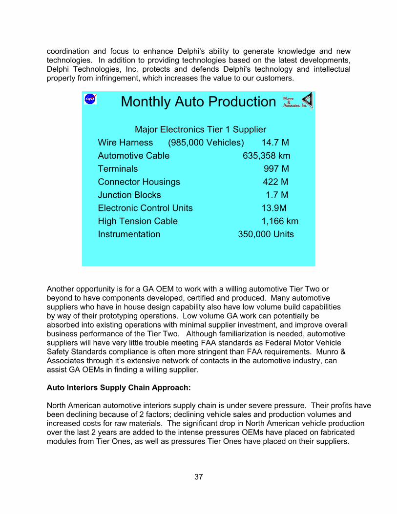
coordination and focus to enhance Delphi's ability to generate knowledge and new technologies. In addition to providing technologies based on the latest developments, Delphi Technologies, Inc. protects and defends Delphi's technology and intellectual property from infringement, which increases the value to our customers.
Monthly Auto Production
Major Electronics Tier 1 SupplierWire Harness (985,000 Vehicles) 14.7 MAutomotive Cable 635,358 kmTerminals 997 MConnector Housings 422 MJunction Blocks 1.7 MElectronic Control Units 13.9MHigh Tension Cable 1,166 kmInstrumentation 350,000 Units
Another opportunity is for a GA OEM to work with a willing automotive Tier Two or beyond to have components developed, certified and produced. Many automotive suppliers who have in house design capability also have low volume build capabilities by way of their prototyping operations. Low volume GA work can potentially be absorbed into existing operations with minimal supplier investment, and improve overall business performance of the Tier Two. Although familiarization is needed, automotive suppliers will have very little trouble meeting FAA standards as Federal Motor Vehicle Safety Standards compliance is often more stringent than FAA requirements. Munro & Associates through it’s extensive network of contacts in the automotive industry, can assist GA OEMs in finding a willing supplier. Auto Interiors Supply Chain Approach: North American automotive interiors supply chain is under severe pressure. Their profits have been declining because of 2 factors; declining vehicle sales and production volumes and increased costs for raw materials. The significant drop in North American vehicle production over the last 2 years are added to the intense pressures OEMs have placed on fabricated modules from Tier Ones, as well as pressures Tier Ones have placed on their suppliers.
37
The interiors supply chain is being reshaped by the current profitability crunch. Tier Ones unable to benefit from the currently more favorable automotive market conditions in Europe or sufficiently reduce systems costs due to inefficient production processes will be searching for new markets to adapt to. Strategies for surviving the profit crunch are being developed by Tier Ones and their affiliates. Strategies holding the most potential for General Aviation OEMs are partnering with Tier Ones and leveraging of automotive component fabrication process savings realized from new materials and new process technologies. GA Approaches to Auto Interiors Supply Chain Strategic Initiatives
Initiative Example/Comment Forward Integration /Partnering Raw material supplier partners with OEMs to eliminate steps Material Substitution Replace high cost incumbents with acceptable substitutes Material Cost Savings Design parts using minimum material Weight Savings Suppliers have materials and technologies on the shelf Reduce Selling Costs Utilize auto e-commerce solution System Cost Savings No local optimization – develop chain strategy Reduce Process Steps Lean Design™, Six Sigma, Use modularity with discretion Parts Consolidation Foundation of value enhancement Unique Solutions New technologies/materials in new applications
Myths About Modularity W. Edwards Deming often suggested that there are more myths in the auto industry than there are in New Guinea. Sometimes, when a subject becomes all the rage, reason gives way to myth. Clearly modularity falls into this category. Here are some of the myths. Understanding them may help you avoid the pitfalls. Modules Always Save Money. They don’t. In many situations, it’s not smart to go beyond the systems level. For example, consider a rear-end module that consists of the deck lid attachment, rear bumper, taillights and a good chunk of the harness. While this might have been considered a natural, the company involved couldn’t make a good business case for this would-be module. One problem: boxing a lot of air. Components coming in discrete or as small systems made a better business case. Design, styling and manufacturability have to be taken into account when making an assessment. Sometimes, no matter how hard you try, modules don’t pay off. Modules Are a Panacea. They’re not. A business case needs to be made for every module. If a module is created as an individual entity, there may be unanticipated problems when it is fitted into the entire vehicle, such as with regard to serviceability. Up-front savings may give way to big costs later.
38

Modules Are Good for Tier One Suppliers. If you’re a supplier of a module that represents 10% of the vehicle, there is a recall and 100% of that recall is related to that module, then there is a good chance that you are going to go out of business. Modules Will Speed Product to Market. Yes…but what happens if one of the module suppliers on a program drops the ball? Self-directed suppliers may show up at meetings and claim they’re on track – when they are off the rails. What happens to the program in that case? Modules Won’t Affect Styling. Consider the underside, or interface of the module. The supplier is going to have to standardize on an approach for its given module. Then it sells this module style to several companies for purposes of achieving economies of scale. This means that the stylists at the companies will have to work with the attachment-point restraints, affecting such things, for example, as cut lines. What’s beneath the skin affects the shape of that skin. This could lead to vanilla products from OEMs using those modules. Modules Will Allow OEMs to Use Same Materials and Processes for Car Build. That’s not the case. Consider a roof, headliner, sun visors, and interior lighting system built as a module, one that’s attached to the vehicle as a single unit. This would require (a) new materials for both the adhesive and the substrate, (b) comparatively complex packing, shipping and scheduling requirements. and (c) the development of the means by which this roof module could be reliably bonded in the assembly plant (including equipment for roof setting and attachment, and higher than normal ceiling height to handle the attachment of the roof to the body in white). Modules Simplify Logistics and Handling. Actually, there is a case of double handling. Make it. Ship it. Pick it up again. Attach it. Not particularly efficient. Modules – Entire Packages – Are Good for OEMs. Some vehicle manufacturers are thinking about having complete vehicles built for them. But aren’t they giving up profound knowledge of the product and process by having this done for them by suppliers? Aren’t they growing their own competition? Much of the investment risk is shifted to the suppliers of modules also. Modules Are Good for Tier One Suppliers. From the standpoint of getting a program, modules can be financially rewarding because it represents a big piece of work. But consider the risks: Programs get cancelled. What is the impact if the cancellation occurs after Alpha tools have been cut? Tooling, engineering, people, materials, testing…and an array of other functions and processes have been paid for. The cost of cancellation is astronomical. It can take years to recoup the loss. Also, large investment increases balance sheet sensitivity to economic downturns.
39

STRATEGIC MAKE / BUY DECISIONS
BEST INSOURCING SITUATION
You can control all subsystems and optimize their interface as
well as iterate on interdependent subsystem development
CAN LIVE WITH OUTSOURCINGYou know how to integrate the item so you may retain competitive advantage even if
others have access to the same item.
WORST OUTSOURCING
SITUATIONYou don’t understand
what you are buying or how to integrate it. The result could be failure
since you will spend so much time on rework or
rethinking
OVERKILL IN VERTICAL
INTEGRATIONYou don’t get to take advantage of supplier capabilities which might speed development and
reduce costs.
BEST OUTSOURCING OPPORTUNITY
You understand it, you can plug it into your process or product, and it probably can be obtained form several sources. It probably does not represent competitive advantage in
and of itself. Buying it means you save attention to put into areas where you have competitive advantage, such as integrating
other things.
A POTENTIAL OUTSOURCING
TRAPYour partners could
supplant you. They have as much or more
knowledge and can obtain the same elements
you can.
Dependent for Knowledge & Capacity
Dependent for Capacity Only
Independent for Knowledge & Capacity
Item
s is M
odul
ar
(Dec
ompo
sabl
e)It
em is
Inte
gral
(N
ot D
ecom
posa
ble)
Modules Can Be Provided by Any Company. Yes…if the pockets are deep enough. Most companies can’t engineer their way into having the capabilities to make modules – and these capabilities can’t be underestimated. They include proficiency in tasks ranging from design to logistics. So they need to become module-capable through acquisition. Partnerships might work – if there is an understanding that although they may start out as equals, one partner will become more equal than the other. Modules Are Bad for Unions. If the union is smart, it can establish a tiered wage structure. In today’s contracts, people working in the trades get different rates than those working on the line. So why not set up an arrangement wherein those that build modules work at a lower wage rate? This means the union increases membership. And OEMs still get reduced costs. Modules Are Beneficial to Consumers. Sometimes. But if there are serviceability issues related to modules being built out of the context of the vehicle, then the vehicle may be in the shop longer than might otherwise be the case. Or it may be that the entire module is replaced, which could have an impact on insurance rates. Either way, the consumer pays.
40

To date, virtually all automotive modular applications have been tactical rather than strategic. There has been little fundamental change in core product architecture where modularity has been tried. If SATS is going to consider modularity, it should be as a strategy, applied rigorously and prudently. A Modular Strategy should comprehend:
• Planning and investing for flexibility • OEMs and Suppliers jointly identifying needs and opportunities • OEMs accepting flexibility investments in price negotiations • Technology enhancements • Product development • Problem solving • Opportunity identification • Manufacturing • Derivative mix • Production volume • Distribution and marketing
Some key questions about Modularity that should be considered by any GA OEM looking at modularity are:
What are the driving forces behind the move towards modular assembly in the automotive industry?
What are the real and false analogies with the computer industry? Why modules now? Who benefits from modular assembly and how? Under what conditions is modularity economically beneficial? What conditions must be present to benefit from modules? What risks accrue to a modular assembly strategy? Are there special engineering issues with modularity? Are there conflicts between modular optimization and systems optimization? What are the interface management challenges to modular approaches? How
should they be managed? How might one determine the optimal sourcing strategy for modules? Under what conditions would modular assembly improve responsiveness to
changing customer desires? Are the current moves to modularity strategic or tactical/opportunistic? How does a modular approach impact strategic flexibility? How can players assess and manage the risks and benefits accruing to a specific
modular assembly approach? How can we assure that capital markets support modular assembly strategies?
(In other words, can suppliers increase margins as well as sales while remaining attractive to automakers?)
41

Modularity Conclusions:
• OEMs should view modularization strategically. • OEM senior management should work with supplier senior management to
understand the basic economics of modularization. o This should take place outside the context of specific program decisions,
including supplier pricing decisions. o Based on principles and examples that are consistent strategically and
operationally. • OEMs and suppliers will have to develop effective inter-organizational cost
management systems to provide focus on modular decisions. • OEMS and suppliers will have to maintain a good working relationship based on
understanding, trust, and mutual commitment. • A clean sheet product presents a unique and rich opportunity to evaluate
structuring the SATS product, process and supply chain architecture for modularity.
Lean Software Development Lean Production and Total Quality Management (TQM), the paradigm shift management tools that revolutionized manufacturing businesses in the 1980s, can also be applied to Software Development with the same dramatic results. Lean Production, which evolved from Taiichi Ohno’s efficient system for creating high quality automobiles (the Toyota Production System) is based on the absolute elimination of waste, in both product and process. His system, together with W. Edward Deming’s teachings on quality management teaches managers how to empower workers to investigate problems and systematically improve business processes. The TQM movement emphasizes a culture of continuous improvement of both product and process. Applying them to software development will generate savings. The following is an extract from a series of articles from Software Development Online tilted “Lean Programming.” “Lean Rule #1: Eliminate Waste The first rule of Lean Programming is to eliminate waste. A value stream analysis identifies all activities in the process and delineates the specific value they add to the final product. The value analysis then attempts to find a different, more efficient way to produce the same value. The documents, diagrams and models produced as part of a software development project are often consumables—aids used to produce a system, but not necessarily a part of the final product. Once a working system is delivered, the user may care little about the intermediate consumables. Lean principles suggest that every consumable is a candidate for scrutiny. The burden is on the artifact to prove not only that it adds value to the final product, but also that it is the most efficient way of achieving that value.
42

Lean Rule #2: Minimize Inventory Contrary to popular belief, inventory is wasteful: It consumes resources, slows response time, hides quality problems, gets lost, degrades and becomes obsolete. The inventory of software development is documentation that isn't a part of the final program. Take requirements and design documents, for example. How important are they to the final product? If you compare them to in-process inventory, it's striking to note that the hours expended to create these documents form a major component of the product's cycle time. Just as inventory must be diminished to maximize manufacturing flow, so, too, must requirements and design documents be reduced to maximize development flow. There are many wastes associated with excess documentation: the squandering of time spent creating and reviewing reports, and the unnecessary work involved in change requests and associated evaluations, priority setting and system changes. But the biggest waste of all is that of building the wrong system if the documentation doesn't correctly and completely capture the user's requirements. We know that users are relatively inefficient at envisioning the details of a system from most documents, and are even less likely to correctly perceive how a system will work in their environment until they actually use it. Even if users could predict exactly how the system should operate, it's unlikely that the way the system is supposed to work months before it's delivered will be exactly the way users need it to work throughout its life span. All of these factors must be considered when we evaluate the value of documentation. Lean Rule #3: Maximize Flow (Reduce System Response Time) In the 1980s, TQM principles taught us how to make products in hours instead of days or weeks. Indeed, rapid product flow shortened cycle times by several orders of magnitude. During the 1990s, e-commerce projects were often able to accomplish in weeks what used to take months or years in the traditional software development world. Yes, in some sense they cheated, exploiting the absence of an established customer base, which allowed unchecked expansion built upon sometimes shoddy components. And many paid the price for this gold rush: A number of the early e-commerce firms, funded largely by speculation, died natural deaths brought on by poor management, code that was anything but robust and lack of discipline. Nevertheless, in the last five years, an abundance of useful software with extremely short cycle times has been deployed. In his article, "Reducing Cycle Time" (Management Forum, Aug. 2000), Dennis Frailey proposes trimming software development cycle time using the same techniques employed to reduce manufacturing cycle time. He suggests looking for and reducing accumulations of work in process, or WIP. Just as in manufacturing, if you reduce WIP, you trim the cycle time. To do this, Frailey recommends using the familiar Lean Production "small batch" and "smooth flow" principles. Iterative development is basically the application of these principles to programming. In this method, small but complete portions of a system are designed and delivered throughout the development cycle, with each iteration taking on an additional set of features. From start to finish, cycle time of any iteration varies from a few weeks to a few months, and each iteration engages the entire development process, from gathering requirements to acceptance testing.
43

Lean Rule #4: Pull From Demand (Make Decisions as Late as Possible) In our videocassette manufacturing plant, we used to think that it would be ideal if our marketing department could forecast exact market requirements. A lot of work went into sophisticated techniques to more accurately predict the future. Then one day we realized that we were doing the wrong thing: It would not be ideal if we had a perfect forecast. Instead, we should relinquish our dependence on forecasts by reducing system response time so dramatically that the system could adequately respond to change, obviating the need for prediction. In a market in which volatile technology requires constant product upgrades, Dell Computer has a huge advantage over its keenest competitors because it doesn't forecast demand; rather, it responds to it by making-to-order in an average of 10 days. While Dell holds only days' worth of inventory, its competitors maintain weeks' worth. Dell's ability to make decisions as late as possible gives the company a significant competitive edge in a fast-moving market. Software development practices that keep requirements flexible as close to system delivery as possible provide a competitive advantage. In a volatile business environment, users can't accurately forecast their future needs. Freezing the design early in a development project is just as speculative as forecasting. Software systems should be designed to respond to change, not predict it. Lean Rule #5: Meet Customer Requirements (Now and in the Future) In his 1979 book, Quality Is Free, Philip Crosby defines quality as "conformance to requirements." The 1994 Standish Group study "Charting the Seas of Information Technology—Chaos" notes that the most common cause of failed projects is missing, incomplete or incorrect requirements. The software development world has responded to this risk by amplifying the practice of gathering detailed user requirements and getting user sign-off prior to proceeding with system design. However, this approach to defining user requirements is deeply flawed. I worked on one project in which the customer wanted a complex system delivered in 10 months. Time was of the essence—10 months or bust. Yet, because the project emanated from a government agency, the contract required sign-off on an external design document before internal design and coding could begin. Several users were involved, and they dragged their feet on signing the documents, concerned that they might endorse something that would later prove to be a mistake. Since there was no easy way to change things after the design documents were signed, they took two months to approve the design. And who can blame them? Their jobs depended on getting it right. So, halfway into a very tight schedule, over two months of time and a lot of paper were wasted in obtaining user sign-off on design documents. Instead of encouraging user involvement, user sign-off tends to create an adversarial relationship between developers and users. Users are required to make decisions early in the development process and are not allowed to change their minds, even when they do not have a clear concept of how the system will work or how their business situation may develop in the future. Understandably reluctant to make these commitments, users will instinctively delay decisions to as late in the process as possible. Note that this instinct is in line with Lean Rule #4: Make decisions as late as possible.
44

The most effective way to accurately capture user requirements is through iterative system development. Developing core features early and obtaining customer feedback in usability demonstrations of each iteration results in a far more correct definition of customer requirements. If we realize that requirements will necessarily change over time, systems must be designed to evolve as necessary. Lean Rule #6: Do It Right the First Time (Incorporate Feedback) Before Lean Production arrived at our videocassette manufacturing plant in the early 1980s, we occasionally had output of marginal quality. To identify and correct this, we tested to find good products and reworked bad products. After implementing the "Do It Right the First Time" rule, we closed down rework stations and stopped trying to test quality into the product after the fact. Instead, we made sure that each component was good at every handoff by employing tests and controls throughout the manufacturing process. In this way, we could detect when a product was drifting away from the specifications and stop production before any bad products were made. "Do It Right the First Time" does not mean "Freeze the Spec." On the contrary, product (and software project) specifications change constantly. Lean discipline demands instantaneous adaptation to changing market conditions, which is best effected with a flexible product architecture that readily accommodates manufacturing change, techniques for monitoring that detect errors before they occur and tests that are designed before manufacturing begins. In his "Industrial Software Metrics Top 10 List" published in the September 1987 issue of IEEE Software, Barry Boehm notes that it costs 100 times more to find and fix a problem after software delivery than in the early stages of design. This observation and the "Do It Right the First Time" rule have been widely used to justify the decision to develop a detailed system design before code is written. The problem with this approach lies in the assumption that customer requirements are static and can be defined by a predetermined system. Because requirements do change—and frequently—throughout the life of most systems, they cannot be adequately fulfilled by a rigid design. "Do It Right" has also been misinterpreted as "don't allow changes." In fact, once we acknowledge that change is a fundamental customer requirement, it becomes clear that "Doing It Right" requires that we provide for change at all stages of a project's life cycle. If we acknowledge that customers may not know what they want at the beginning of development and that their needs might change midstream, we must incorporate a method of obtaining customer feedback during development. Instead, most software development practices include a complex "change control process" that discourages developers from responding to user feedback. Far from ensuring a quality result, these change-resistant processes actually get in the way of "Doing It Right." Lean Programming employs two key techniques that make change easy. Just as Lean Production builds tests into the manufacturing process to detect when the process is broken, Lean Programming builds tests into the beginning of the development process. As programming proceeds and changes are made, the unit and regression tests are run. If the tests don't pass, programming is stopped until the problem is found and corrected. A comprehensive testing capability is the best way to accommodate change throughout the development process.
45

The second technique that facilitates change is recapturing, or improving the design of existing software in a controlled and rapid manner. With refactoring, initial designs can focus on the basic issue at hand rather than speculate about other features that may be needed in the future. Later in the process, refactoring techniques can incorporate these additional features as they are required, making it easy to accommodate the future if and when it becomes the present. Lean Rule #7: Empower Workers A basic principle of Lean Production is to drive decisions down to the lowest possible level, delegating decision-making tools and authority to the people "on the floor." As Paul Adler noted in his article, "Time-and-Motion Regained" (Harvard Business Review, Jan.- Feb. 1993), when Toyota took over GM's manufacturing plant in Fremont, California, in 1983, it inherited workers with the worst productivity and absenteeism record in the industry. Within two years, those same workers, organized into teams trained in work measurement and improvement techniques, had doubled their quality and productivity scores. Often when software development environments under-perform, the instinctive reaction is to impose more rigid processes, specifying in greater detail how people should do their jobs. Lean Production principles suggest exactly the opposite approach. When there are problems in manufacturing, a team of outside experts is not sent in to document in more detail how the process should be run. Instead, people on the manufacturing floor are given tools to evaluate and improve their own areas. They work in collaborative teams with the charter to improve their own processes and the links to nearby processes for which they are suppliers or customers. Their supervisors are trained in methods of forming and encouraging work teams to solve their own problems. Lean Programming similarly prizes people and collaborating teams over paperwork and processes. It focuses on methods of forming and encouraging teams to address and resolve their own problems, recognizing that the details must be determined by the people doing the work. Software development involves the handoff of information at least once (from user to programmer) and often more than once (from user to designer to programmer). One school of thought holds that it's best to transfer all such information in writing, but in fact, a great amount of tacit knowledge is lost by handing off information on paper. It's far more effective to have small collaborating teams work across the boundaries of an information handoff, minimizing paperwork and maximizing communication. Lean Rule #8: Ban Local Optimization In the 1980s, the worst enemy of Lean Production was often the accounting department. We had big, expensive machines in our plant, and the idea that they should not be run at full capacity was radical, to put it mildly. The accountants didn't want to abandon our daily work-in-process (WIP) inventory reports just because there was virtually no WIP to report. A generation of accountants had to retire before it became acceptable to run machines below full capacity, and designing machines for rapid changeover rather than highest throughput remains a tough sell even today. After 20 years, Lean Production is still counterintuitive to those who lack a broad business view.
46

In this context, let's examine the role of managing scope in a software development project. Project managers have been trained to focus on managing scope, just as we in manufacturing concentrated on maximizing machine productivity. However, Lean Programming is fundamentally driven by time and feedback. In the same way that localized productivity optimization weakens the overall manufacturing process, so focus on managing scope impairs project development. Think about it—holding the scope to exactly what was envisioned at the beginning of a project offers little value to the user whose world is changing. In fact, it imparts anxiety and paralyzes decision-making, ensuring only that the final system will be outdated by the time it's delivered. Managing to a scope that's no longer valid wastes time and space, necessitating inefficient issue lists, extensive trade-off negotiations and multiple system fixes. However, as long as limiting a project to its original scope is a key project management goal, local optimization will flourish—at the expense of the project's overall quality. Lean thinking dictates that scope will take care of itself if the domain is well understood and there is a well-crafted, high-level agreement on the system's function in the domain. Scope will take care of itself if the project is driven in time buckets that aren't allowed to slip. Scope will take care of itself if both parties focus on rapid development and problem-solving, and adopt waste-free methods of achieving these goals. Lean Rule #9: Use Evolutionary Procurement (Partner with Suppliers) Lean Production didn't remain within the confines of the manufacturing plant. Once the idea of partnering with suppliers was combined with an understanding of the value of rapid product flow, Supply Chain Management was born. People began to realize that it took tons of paper to move material between companies. Moreover, the paperwork was more expensive than one might expect, as was the ensuing delay in product flow. Today, by cutting the cost of business-to-business transactions, Web portals have generated billions of dollars in savings. Supply Chain Management made companies take a close look at their business-to-business contracts. All too often, they focused on keeping the companies from cheating each other. In addition, it was common to pit one vendor against another to ensure supply and to obtain the lowest cost. Again, Lean Production changed this paradigm. Deming taught that trust-based relationships with single suppliers create an environment that best benefits both companies. Throughout the 1980s, companies revitalized their supply chains by reducing the number of suppliers they used and working as partners with those who remained. The high quality and creativity of these supply chain partnerships far outweighed the putative benefits of competitive bidding and rapid supplier turnover. Partner companies helped each other improve product designs and product flows, linking systems to allow just-in-time movement of goods across several suppliers with little or no paperwork. The advantages of this collaborative supply-chain relationship are lasting and well documented. Wise organizations realize that traditional software development contract practices generate hidden wastes. As the manufacturing world revealed in the 1980s, trusted relationships with a limited set of suppliers can yield dramatic advantages. Freed from the adversarial relationship created by a concentration on controlling scope and cost, software development vendors can focus on providing the best possible software for their
47

customers, stabilizing requirements as late as possible in the development process to provide the greatest value for the available funds. Lean Rule #10: Create a Culture of Continuous Improvement When software development seems to be out of control, organizations often hasten to increase their level of "software maturity" with awards and certifications. This might seem to be in line with good manufacturing practice, in which ISO 9000 certification and Malcolm Baldridge awards are sometimes equated with excellence. However, these process-documentation programs indicate excellence only when the documented process excels in the context of its use. In many software development projects today, excellence means the ability to adapt to fast-moving, rapidly changing environments. Process-intensive approaches such as the higher levels of Software Engineering Institute's (SEI) Capability Maturity Model (CMM) may lack the flexibility to respond rapidly to change. In a recent e-mail advisory (E-Projects in India, Cutter Consortium's e-Project Management Advisory Service, March 1, 2001), Jim Highsmith highlights the tension between such heavyweight methodologies and the light- weight development models inspired by Lean Production. One suspects that process-documentation certification programs may stifle, rather than foster, a culture of continuous improvement. Deming would probably turn over in his grave at the tomes of written processes substituting for his simple Plan-Do-Check-Act approach:
• Plan: Choose a problem. Analyze it to find a probable cause. • Do: Run an experiment to investigate the probable cause. • Check: Analyze the data from the experiment to validate the cause. • Act: Refine and standardize based on the results.
Iterative development can effectively employ the Plan-Do-Check-Act method. During the first iteration, the handoff from design to programming or programming to testing may be a bit rough. It's OK if the first iteration provides a learning experience for the project team, because the subsequent iterations will allow the team to improve its process. In a sense, an iterative project environment becomes an operational environment, because processes are repeated and Deming's techniques of process improvement can be applied from one iteration to the next. Product improvement is also enhanced in the iterative process, particularly if refactoring is used. In fact, refactoring provides a tremendous vehicle to apply the principle of continuous improvement to software development. However, we need an improvement model that can span more than a single project. We must improve future project performance by learning from existing ones. Here again, Lean Production can point the way. During the 1980s, the set of practices summarized in the 10 rules of Lean Production were adopted widely across most manufacturing plants in the U.S. and Europe. These practices then spread to service organizations, logistics organizations, supply chains and beyond. In these multiple domains, application of Lean Production principles has engendered remarkable and continuing success. The simple tenets of Lean Production have effected dramatic improvements in a myriad of industries. Applied to software project management as Lean Programming, these practices will lead to the highest quality, lowest cost, shortest lead-time software development possible.”
48

Digital Technology Migration to General Aviation Current and near future integrated glass cockpit offerings from the major avionics manufactures lack a uniting foundation. Avionic manufactures add on stand-alone fixes and technology boxes to share limited information with a few other products. This approach results in limited increased functionality and does so at the expense of increased complexity and cost. Today’s Instrument Panel The Next Step
Munro recognizes the explosive market pull for vehicle telematics that provide an information rich and safe environment for business and personal travelers. While Munro’s lean technology transfer process can pull these from the automotive industry for Lean Design of small airplanes, lean integration of telematics into small airplane cabins/cockpits will require a further knowledge based innovation. Smart Deck by B. F. Goodrich The dawn of a new era has arrived with the development of SmartDeck™, technology specifically created for general aviation aircraft. This revolutionary, integrated avionics suite will enhance flight safety through the application of leading edge technology, human factors engineering, and "smart" systems integration. SmartDeck™ economically provides general aviation pilots with an electronic situational display of primary flight cues, as well as moving map, weather, traffic, and terrain information on 10" diagonal flat panel displays. Unprecedented situational awareness ensures that the pilot perceives the attitude, location, and condition of the aircraft and surrounding environment. SmartDeck™ technology fuses data from all available aircraft sources to give pilots the “big picture" with Highway-In-The-Sky and moving map presentations. SmartDeck™ will also monitor engine and aircraft systems for early detection of potentially hazardous situations Smart Deck™ could be further improved with automotive technologies that permit the pilot to keep his eyes on the flight path and hands on the steering controls.
49

. The Eclipse 500
The Eclipse 500 features an all-glass cockpit with state-of-the-art avionics provided by Avidyne Corporation and BAE Systems. Multiple onboard computers provide redundancy while controlling and monitoring all aspects of the aircrafts performance and vital functions. By using standard software and hardware in an open architecture, Eclipse avionics will be powerful, cost-effective and highly flexible. The avionics suite features active-matrix color liquid crystal displays, presenting information such as attitude indication, speed, altitude, navigation data, engine parameters, weather depictions, autopilot settings, and more. The visual presentation of the data is clear and easy to understand, enabling the pilot to respond naturally and intuitively.
50
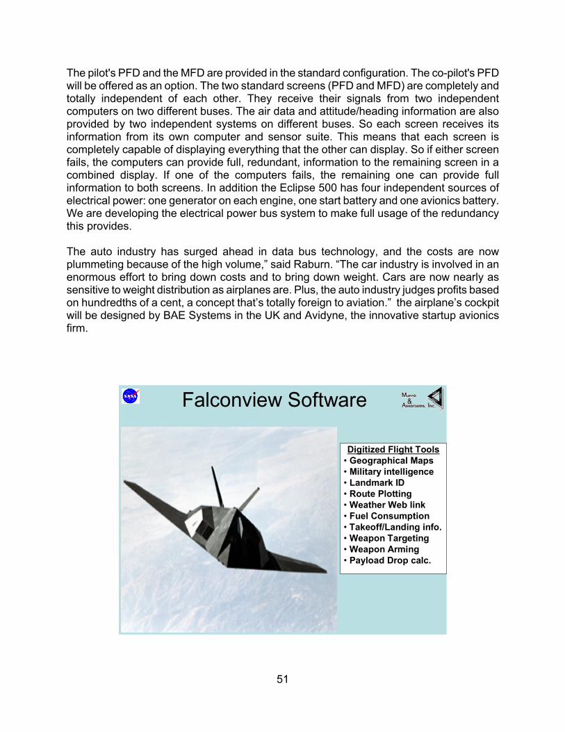
The pilot's PFD and the MFD are provided in the standard configuration. The co-pilot's PFD will be offered as an option. The two standard screens (PFD and MFD) are completely and totally independent of each other. They receive their signals from two independent computers on two different buses. The air data and attitude/heading information are also provided by two independent systems on different buses. So each screen receives its information from its own computer and sensor suite. This means that each screen is completely capable of displaying everything that the other can display. So if either screen fails, the computers can provide full, redundant, information to the remaining screen in a combined display. If one of the computers fails, the remaining one can provide full information to both screens. In addition the Eclipse 500 has four independent sources of electrical power: one generator on each engine, one start battery and one avionics battery. We are developing the electrical power bus system to make full usage of the redundancy this provides. The auto industry has surged ahead in data bus technology, and the costs are now plummeting because of the high volume,” said Raburn. “The car industry is involved in an enormous effort to bring down costs and to bring down weight. Cars are now nearly as sensitive to weight distribution as airplanes are. Plus, the auto industry judges profits based on hundredths of a cent, a concept that’s totally foreign to aviation.” the airplane’s cockpit will be designed by BAE Systems in the UK and Avidyne, the innovative startup avionics firm.
Falconview Software
Digitized Flight Tools• Geographical Maps• Military intelligence• Landmark ID• Route Plotting• Weather Web link• Fuel Consumption• Takeoff/Landing info.• Weapon Targeting• Weapon Arming • Payload Drop calc.
51

GA can take a lesson from what has already been done in the military. After using a very manual and error prone mission planning system During the Gulf War, Air National Guard reservists realized before their Air Force counter parts that there was a better way to plan mission flights. They saw the role that software and Personal Computers could play in flight planning and execution. The reservists turned to commercial software developers as well as to the Georgia Tech, whose researchers were experienced with math models and geographical data sources required for a sophisticated mapping system. The result was Falconview, a PC based mission planning system. Falconview cuts the mission planning process for a standard sortie from 7 hours to less than 20 minutes. It increases planning accuracy through the use of precise digital data and aeronautical mapping tools. Its easy to use and economical. Its been deployed by the US Air Force worldwide. Today our military pilots use a laptop PC containing digital maps of the world, digital images and updates from military intelligence. The pilot can easily locate landmarks, hostile force deployments, plot his route, check safety parameters, weapons systems, link to web based weather source, and prepare flight plans and maps. If he wants to know the elevation of a mountain, he clicks on it and its precise latitude, longitude, and altitude reading is displayed. Pilots then load the pre-mission planning files into the aircrafts computers for use in flight. The point is ….. GA can use the same thing … modified for civilian apps.
The RQ-4A Global Hawk is a high-altitude, long-endurance unmanned aerial reconnaissance system designed to provide military field commanders with high resolution, near-real-time imagery of large geographic areas. Advanced technology sensors, a range greater than half-way around the world, and the ability to remain in flight for long periods of time, enables the Global Hawk to provide the war fighter with the essential intelligence needed to achieve information dominance throughout the ever-changing battle-space. The aircraft's 13,500 nautical mile range and 36 hours of endurance, combined with satellite and line-of-sight communication links to the ground segment, permit worldwide operation of the system. High-resolution sensors, which can look through adverse weather (day or night), from an altitude of 65,000 feet, can conduct surveillance over an area the size of Illinois in just 24 hours.
52

The superior performance of the Global Hawk system will significantly enhance the U.S. military's ability to prevail in all types of operations, from sensitive peacekeeping missions to full-scale combat. The question remains, given that Global Hawk demonstrates the feasibility of the SATS vision; what technologies from Global Hawk can migrate to GA?
Auto Technology - The Digital Car Since NASA's SATS vision has always been built upon a latent mass market pull for a 4X highway speed, almost all weather, safe, reliable and affordable personal air travel capability. Munro contends that to capture the volume latent market demand, SATS planes must include customer convenience technologies (CCT) in the terms of physical and ergonomic comfort as well as telematics and information access. An appropriate analogy would be that if better roads, smart signs and traffic lights are developed without new cars that can use these capabilities, there won’t be an improvement in travel capacity or quality. Thus at the end of the SATSLab demonstrations new technologies will be required in the airplane, unless these are integrated into the cockpit environment using Lean Design™ processes that create an affordable automotive convenience technology environment, volume public travel by small airplanes will not occur. The 21st century travel customer whether ground or air, using automobile, airline or GA, will demand an information rich, comfortable and convenient travel environment. Thus critical to SATS travel success are automotive and consumer electronics CCTs, and harmonized cabin environments in both new and existing SATS capable airplanes. SATS travel will face massive customer rejection if the SATS capable travel airplanes leave behind CCTs such as telematics; leaving them usable only by the conventional GA non-volume aficionado market. The GA industry will need to consider and have solutions ready for the added electrical loads that new CCT bring to aircraft. Once again, the auto industry provides an excellent model and supply chain resource for GA. The following is a brief synopsis of some automotive technologies that may be compatible with General avaiation. 42 Volt Systems A seismic shift is underway in the automotive industry, although it will take 20 years for the shift to be complete and all new vehicles world wide are equipped with 42 – volt power systems. An international consortium of 47 automakers and suppliers is focused on establishing 42 volts a the international standard and addresses the technical issues needing research before that standard can be implemented. Two industry trends are driving the push to higher voltages: increased power demands on vehicle electrical systems and the industry's need to improve fuel economy and emissions are making current 12-/14-volt electrical systems inadequate.
Higher-voltage systems will have a far-reaching effect on the auto industry. Not only does the availability of higher voltage enable advanced features, it will drive manufacturers to rethink and, possibly, redesign everything from light bulbs to major components, smaller, lighter, and lower cost.
53

Energy for New Technology With the 42-Volt System, technologies that were previously impractical or impossible are now feasible. For example, higher voltages will enable more effective and efficient use of by-wire technologies, ride control systems, electro-magnetic valve trains, and integrated starter/generators. In addition, wiring bundles and semiconductors could be made smaller while transferring more power. The new voltage standard could also improve braking, enabling the use of more powerful motors in both motor-based and solenoid-based brake systems. Power and Signal Distribution As vehicles complete the transition from a dual-voltage (14-/42-volt) system to a single 42-volt system, power and signal distribution architecture will be reconfigured, resulting in reduced wire gauge, smaller wire bundles, smaller connection systems, and decreased cost and mass. In addition, installation and routing of the wiring system will be simplified, creating the following new design opportunities. New Electric and Electronic Features Coming to Market:
• The Integrated Starter Alternator • Electrically Driven Air Conditioning] • Electric Power Steering and or Power Assisted Steering • Electric Windshield Heater • Airbag Systems • Adaptive Cruise Control • Electric Cabin Heating • Electrically Heated Catalytic Converter • Electrically Heated Steering Wheel • Electronic Stability Control • Electromechanical Valves • Telematics/Information Navigation and Entertainment Systems • Accelerate By Wire
Drive By Wire Technologies One important rationale for the move to 42 volts is that it makes practical the use of power semiconductors for controls. Sophisticated controls are needed for many of the following features. Power electronics, semiconductor switches and relays will be alternatives to electromechanical types used today.
• Steering Systems While Electric Power Steering system has improved steering on small to midsize vehicles, the technology cannot presently be applied to larger vehicles. The increased power availability of the 42-volt system will enable it’s use on full-size vehicles. The 42-volt system will also enhance steer-by-wire technology, allowing
54

for smaller mechatronic actuators that feature lower mass and improved performance.
• Chassis Systems The 42-volt system will facilitate the development of electric power brakes and advanced ride control systems.
• Thermal Systems Engine cooling fans and HVAC blower motors that run on 42 volts provide increased efficiency.
• Interior Systems Using 42-volt systems, OEM’s can offer more efficient operation and increased power to features such as power sliding doors, power lift gates, power windows, Electronic Locks.
• Electronics Tier One suppliers will provide DC/DC converters, inverters, battery management, and other electronic controls to meet higher voltage requirements.
• Engine Management Systems Tier 1 suppliers are reviewing the effects of 42 volts on engine management systems and is developing technologies designed to improve performance, durability, and size reduction.
Night Vision GM had to pay Raytheon approximately $100M to bring battlefield Night Vision Technology to Cadillac. It then had to be revised to meet automotive size and cost requirements. SATS and GA could potentially benefit from GMs investment in Night Vision Technology. This is why SATS needs a Munro team to identify and adapt the best technologies from across industries for achieving the SATS travel vision. Raytheon Night Vision Infrared Imaging Systems – the system uses a small rectangular heads up display (HUD), developed by Delphi Delco Electronics, on the driver’s lower windshield to reveal sights that otherwise would not be possible to see in low visibility conditions. This system currently sold in Cadillac’s, uses a shatterproof refractive optical lens system to gather infrared (IR) energy. The forward mounted sensor views the onrushing environment through an infrared-transparent window approximately three inches in diameter. The sensor incorporates an internal heater to prevent snow and ice buildup on its small front window for winter operations. Just behind this “camera” window, refractive optics focus infrared energy on a 1-inch square detector. The Night Vision System can detect thermal temperature differences in objects as small as 1/3 of a degree. Information from this detector is passed to sensor electronics that translate the data into a reversed (negative) black and white image presented on the HUD. The system is like a video camera that shoots its thermal footage in the invisible-to-the-eye IR realm. To minimize the absorption of IR photons by water molecules in the air, the sensors are tuned for medium am long wave IR. As a result, heavy rain or fog with dense water droplets can only somewhat diminish the Night Vision system’s range and sensitivity.
55
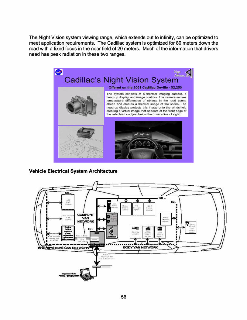
The Night Vision system viewing range, which extends out to infinity, can be optimized to meet application requirements. The Cadillac system is optimized for 80 meters down the road with a fixed focus in the near field of 20 meters. Much of the information that drivers need has peak radiation in these two ranges.
The Night Vision system viewing range, which extends out to infinity, can be optimized to meet application requirements. The Cadillac system is optimized for 80 meters down the road with a fixed focus in the near field of 20 meters. Much of the information that drivers need has peak radiation in these two ranges.
Cadillac’s Night Vision SystemOffered on the 2001 Cadillac Deville - $2,250
Cadillac’s Night Vision SystemOffered on the 2001 Cadillac Deville - $2,250
Vehicle Electrical System Architecture Vehicle Electrical System Architecture
56
56

As electronic system design in the automotive industry is migrating from hardware first to software first, architectural standardization and leadership becomes a key success factor for the industry as a whole as well as individual players. The automotive electrical market is becoming like the software market where the law of increasing returns is where significant value is created through standard architectures. GA will benefit greatly if they can share such components with automobiles developed under the rigor of standard architecture. This is true because standard architectures:
• Create economies of scale with volumes which enable mass production at affordable prices.
• Allow commoditization of components. • Enable externalities: extended functions and complimentary products, E.g. as
more car makers use a standardized operating system platform within their ECUs, more suppliers will write software and offer extended functionalities for that platform.
• Permits engineering learning continuity by investing only once in learning the architecture.
• Enable re-use of components The consumer demands driving electrical architecture design are; Telematics, Navigation Systems, On Board Computers, In-Vehicle Entertainment, Computer Systems, Consumer Electronic Devices (PDAs and Cell Phones). OEMs are concerned with systems Integration and interface, with no compromise of safety, security and integrity, while minimizing cost, complexity, packaging and regulatory issues. Their scope and plans is for millions of vehicles in the near future. The vehicle is defined by the OEM, and because they have responsibility for vehicle making as a whole, the OEM has to integrate components, modules, subsystems and complete functional systems from different suppliers into the complete vehicle system. This integration aspect is of key importance for the future competitiveness of the OEM. A well defined architecture is a prerequisite for the cost and time efficient integration of new functionalities and technologies. Without the integration support of such an architecture, the OEM will be just connecting black boxes which are delivered by the suppliers to the vehicle data bus. This increases the cost of adding subsystems and sacrifices the advantage of synergies and vehicle wide optimization. Successful companies keep the core development of the general purpose architecture internally controlled while they externalize the maximum possible fraction of actual system implementation. Given the strong market pressure to integrate all types of computer systems, it remains to be seen whether the automotive industry will create its own higher-level standards or will actively participate in existing standardization bodies to integrate information processing systems onboard the vehicles seamlessly into the emerging information infrastructure. This window may be an opportunity for GA to explore partnering with auto OEMs and suppliers for developing common systems and components.
57

Telematics
Telematics • Telematics delivers services to and from the
vehicle
• Highly customized to specific vehicle architecture
• Location identification via GPS
• Enhanced safety and security for drivers
Within 5 years 50% of new cars will have driver information systems. These systems will have the designed in flexibility to integrate devices and create different experiences based on driver preferences. The telematics modules integrates a phone, global positioning satellite receiver, and digital processor to allow communication between a vehicle and a service call center. By assessing a vehicle’s data bus, the call center can provide navigation assistance, remote diagnostics and remote door lock/unlock plus other services that help enhance safety and security In vehicle systems can be built-in or added through connections for cell phones or PDAs. On board systems get information from a GPS satellite or a cellular-network based location system. Location information from the vehicle is transmitted via a wireless network carrier to a service provider that sends back content such as traffic, weather, or news – tailored to the driver and the car’s location.
Voice Activation – Auto OEMs see voice technology as an in vehicle enabler for complex tools while allowing drivers to keep their hands on the wheel and their eyes on the road. It allows other things to happen, such as intuitive communication with other on board systems. There are 2 parts to voice technology: speech synthesis and speech recognition. Speech synthesis refers to a computer-generated, human sounding voice that relays information to the user. In an aircraft, speech synthesis can be used for example, to give navigation and guidance instructions or provide a pre-recorded alert.
58

Speech recognition allows a driver to communicate with his car. All voice processing in done aboard the vehicle through a speech engine processor which then sends the appropriate electronic commands to a Telematics device. There are challenges facing voice technology, primarily in the areas of recognition accuracy, cost and driver distraction. Auto OEMs will be working to improve voice activation accuracy and price competitiveness through integration into the vehicles systems. The Phase I work will apply the methodology described below to select which of these two technologies to select for transfer to GA.
Services and Features Navigation - The Infotainment PC allows drivers to select a destination and receive a color map-based navigation system with turn-by-turn instructions. Voice recognition - Occupants can activate the functions through voice command, so they can keep their "hands on the wheel and their eyes on the road," an important safety design feature to Delphi and to Cadillac. Text-to-speech - E-mail messages can be read back to occupants. Voice memo - Voice messages may be recorded, stored and played back at a later time. Infrared port - This function allows handheld devices such as portable phones and personal data assistants to exchange information. CD/CD-ROM drive - Plays music CD's and reads CD-ROM databases such as maps. Compact flash slot - Allows for expanded memory and software upgrades. Cell phone integration unit - Docks a portable cell phone and allows cell phone control via voice recognition or front panel keypad. Safety Systems Technology Automotive safety typically focuses on occupant protection during a collision. However, Delphi is developing the Integrated Safety System (ISS), a broad portfolio of more than 50 current and future safety-related technologies that will help reduce the potential for collision and mitigate the effects of a collision if one occurs. Delphi can meet customers’ specific requirements for any vehicle program by designing an entire system, creating a package of multiple elements, or supplying individual products. With a vehicle-wide systems approach, ISS technologies are designed for five specific driving states. Leveraging these safety related technologies to GA would provide comprehensive SATS with greatly enhance safety systems of current and future aircraft. Normal Driving State—Delphi provides technologies to help keep the driver comfortable and alert, such as our Forewarn™ adaptive cruise control, power adjustable pedals, seat belt comfort features, and automatic windshield fog prevention. Warning State—An array of functional alerts, including Delphi’s Forewarn Collision Warning Systems, will aid the driver in recognizing a detectable threat and provide
59

warnings so the driver can resume a normal driving state. Collision Avoidable State—If the potential for collision is detected and can be avoided, several vehicle control enhancements are initiated to supplement the driver’s actions. These include our Forewarn Collision Avoidance System, and our Unified Chassis Control—for braking, suspension, and steering. Collision Unavoidable State— Occupant protection is enhanced by the portfolio of technologies in Delphi’s Advanced Safety Interior. Post-Event State—Technologies are being designed to help reduce risks following an accident. These include automatic fuel and electrical power shutoffs, easy vehicle exit features, unfired airbag disarming, and emergency services notification. With competencies in all major vehicle systems, Delphi has the unique capability to integrate multiple functions into one comprehensive vehicle-level safety system. The Integrated Safety System demonstrates Delphi’s commitment to “Driving Tomorrow’s Technology.” Delphi’s Integrated Safety System in Delphi’s ISS strategy, some vehicle safety technologies will be focused on helping to reduce the probability of an accident occurring. Delphi terms this the “Avoidance Zone” of the ISS model. Other safety technologies will concentrate on helping reduce the effects of an accident should one occur. This is the “Mitigation Zone.”
Normal Driving State• Adaptive Cruise Control• Driver monitoring system• Emergency sickness alert• Inclement weather indicator• Night vision • Roadway service condition• Adjustable head light direction• Adaptable Interiors
Warning State• Collision warning• Blind spot follow vehicle warning• Lane Change warning• Lane Roadway departure warning• Low Tire Pressure warning• Roll-over warning• Back-up parking assistance• Warning tell-tales
Collision Avoidance State• Chassis control• Roll Over prevention• Steer by wire• Brake by wire• Throttle by wire
Collision Un-Avoidable State• Anticipatory crash sensing• Re-usable counter measures• Emergency door locks• Occupant characteristics positioning• 360 degree crash severity sensing• Adaptable counter measures• Adaptable structures• Pedestrian injury reduction
Post Collision State• Fire extinguisher system• Mayday system• Easy exit• Vital sign monitoring• Fuel System Cut-Off• Emergency Lighting• Electrical Power Disconnect
Automotive Cockpit States
60

Automotive Approaches for General Aviation Systems Vehicle Architecture Development Automotive Definition: A set of product and process standards that define the range of dimensional flexibility, a minimum set of components, a set of common interfaces and minimum manufacturing variation to meet customer requirements and maximize profit. Need for a common definition:
• Lack of a common definition prevents us from having a common understanding during product related discussions
• Variation in understanding makes it difficult to agree on architecture strategy • Enables more effective dialog on architecture related issues
Elements of Vehicle Architecture: Architecture consists of three parts:
1. Components 2. Interfaces 3. Manufacturing System
A set of vehicles that share an architecture are similar in size and have:
• A common set of major components • Common component interfaces • Common manufacturing system
1- Components – basic building blocks of either systems or modules
1. Establish Major Components o These components are generally invisible to the customer; and
emanate from the systems like; structure, propulsion, fuel and exhaust, electrical, braking, etc.
2. Interfaces between major components (the way they interact and
connect), such as seat to floor or engine to fuselage 3. Manufacturing system (the process by which components are created and
assembled)
61

Dealing with Architectural Issues:
• Effective decisions concerning architectural issues enables: o Reduced cost
Engineering resources Component sharing (reduce total number) Tooling and investment Manufacturing flexibility Rapid learning cycles
o Increased revenue o Increased design throughput o Focused product differentiation o Faster to market
• Architecture also enables supply chain design strategies to be implemented. Supply chain design consists of 3 components:
o In-sourcing/Out-sourcing (The Make/Buy or Vertical Integration Decision) o Supplier Selection (Choice of suppliers and partners for the chain) o The Contractual Relationship (Arm’s length, joint venture, long-term
contract strategic alliance, equity participation, etc.
Product Process Supply Chain
DesignDetailedPerform .
Specs.& Funct.
Architect.M odular
Vs.Integral
UnitProcesses
Tech.& Equip.
M fg. Syst.Functional
Cellular
S.C. Architect.Orgs Set& Alloc.O f Tasks
Logistics & CoordSystem
Auton vs.Integrated
-Focus-A rchitecture-Technology
Architecture decision modelIllustrating the im perativeof a concurrent approach
Objectives for creating vehicle architecture:
• Common set of major components across derivatives • Common interfaces • Common manufacturing processes
62

• Balancing of these objectives with customer needs, business objectives and supply chain objectives
Architectural Dimensions:
• Functional Architecture: Performance specification; how key functions are served and integrated > systems
• Physical Architecture: How the vehicle is sub divided physically for manufacture
(and how it is assembled) --> Components, Sub assemblies, Modules
• Sourcing/ Processing Architecture: Who does what part of the engineering and manufacturing tasks and how--> Process Flows, Details, Investment and Sourcing.
s
A
Automotive Architectural Components and Interface
utomotive Architecture Benefits:
• Major components are kept to a minimum by sharing within and across architectures.
63

• Selection of a specific set of major components comprehends requirements and range of applications across vehicle derivatives.
• To enable mixing and matching of major components from the BOM at minimum
cost, interfaces must accommodate multiple components.
• Architecture interface standards assist in managing component sharing. They prevent changes in one component from causing changes in adjacent or interacting components, i.e., the discipline of architectural interface standards prevents changes from ripping through the vehicle causing BOM proliferation.
• Dimension and proportion variation is managed by defining ranges for key
dimensions driven by marketing and other requirements. Automotive examples:
• Wheelbase Front H Point • Front over hang Rear H point • Rear over hang Vehicle width
Development of Vehicle Architecture:
• Starts with the development of an Architectural Plan which consists of
o Market and segmentation definition o Definition of derivatives from a single architecture
• Development of the architecture begins with a balanced architecture concept
• The architecture is further refined with a focus on the first vehicle to be derived from the architecture.
Architecture Template Outline: • Market Opportunity • Vehicle/Architecture Plan • Key Architecture Targets • Package Description • Component Strategy • Major Components • Criteria List
• Financial Targets • Resource Timing Plan • Manufacturing Strategy • Airframe Assembly Flow • Risks Issues • Architecture Example
Automotive Example of Modular Vehicle Architecture Tipo Analysis Result
Fiat used modular assembly to allow the high level of automation in general assembly. Analogous to the modular build of a computer (where circuit boards are sub assembled
64

using automation and then installed Into the computer chassis), Fiat has designed the Tlpo to be built as modules. This allows the modules to be sub assembled away from the main assembly line in stopped stations where there is clear access for tooling and part orientation.
Fiat has provided principal locating gage holes for each module that is used by the robotic tooling to grip and locate the parts. Maintaining the same gage holes in the base part allows changes in module content to remain invisible to the final line automation. For example, the IP option content can vary, and in fact, the whole customer perceived styling can be redesigned, and as long as these two body interface gage holes are maintained, the final line automation can still be used.
Lean principles were evident wherever automation was used on the Tipo. Minimization of parts, simple loading motions, automation friendly fasteners, clear access to fasteners, and integral plastic clips all combined to make the Tlpo easy to assemble. The front suspension module is an excellent example displaying ld principles: all components load from the same side with one straight down motion, and all fasteners are vertical and driven from the same side.
Wherever there was automatic fastening used on the Tipo, fasteners were used that consisted of a hex head bolt with an integral washer and a combination dog-point, cone-point tip (to minimize cross threading and help self locate.)
Fiat justified their design using a total system cost approach. This was demonstrated across the vehicle where component cost was increased due to multi-functionality, to allow savings in assembly labor and material handling. For example gage holes added to stampings, brackets and straps pre-attached to components, and part features added to guide components during assembly. Parts packaging was also designed to allow for easy gripping and access. This again shows a total systems approach to the implementation of this architecture. lean design, applied in a structured systems engineering environment allowed this design to be successfully implemented
65

66
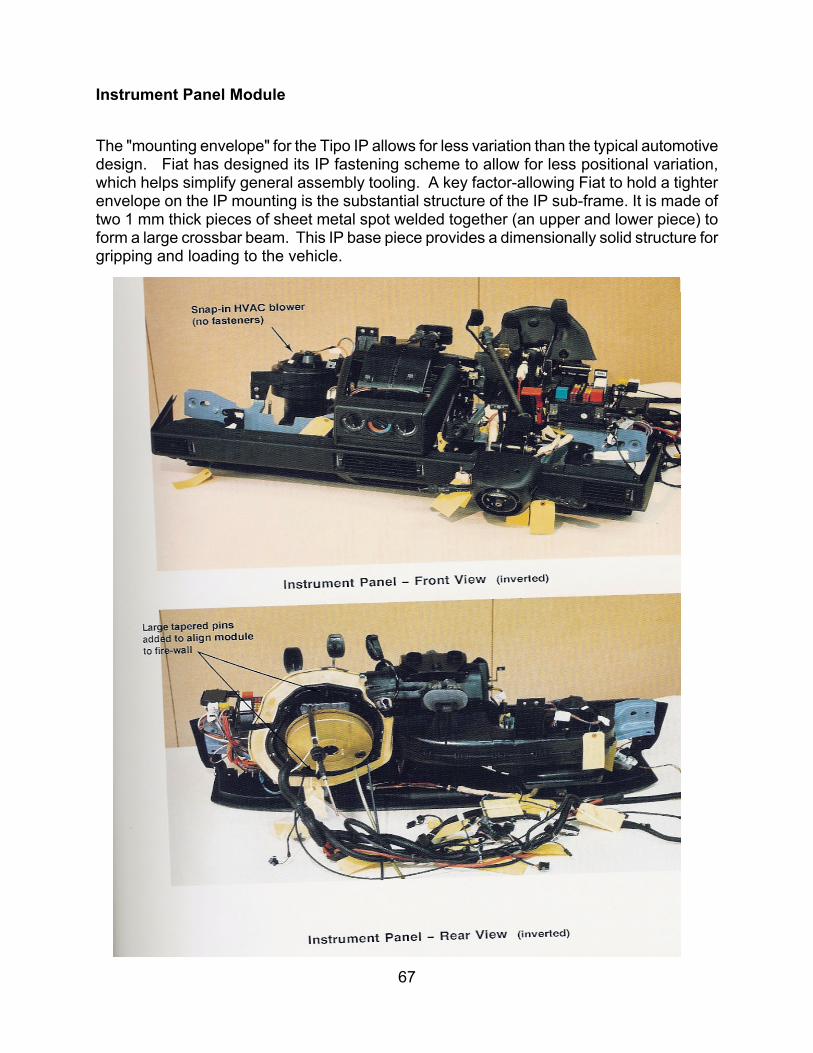
67
Instrument Panel Module The "mounting envelope" for the Tipo IP allows for less variation than the typical automotive design. Fiat has designed its IP fastening scheme to allow for less positional variation, which helps simplify general assembly tooling. A key factor-allowing Fiat to hold a tighter envelope on the IP mounting is the substantial structure of the IP sub-frame. It is made of two 1 mm thick pieces of sheet metal spot welded together (an upper and lower piece) to form a large crossbar beam. This IP base piece provides a dimensionally solid structure for gripping and loading to the vehicle.

68

Summary Of Automotive Approaches The following matrix proposes automotive features and technologies for major functional areas of a General Aviation aircraft.
Functional Area Automotive
Approach / Feature / Material
New / Automotive Processing Technology
Pilot / Passenger Interface
Seats
Pilot
> Integral Restraints – 3 point > Belt pre-tensioners > Integral Arm rests > Head Rests - COTS > Integral Heat & Cooling > Adjustable Lumbar > Aeron
> Hydro formed > Blow Molded > Plastic Injection Molded Seat Backs > Thixotropic Molding > Formed Sheet Metal > Foam in place cushions > Aluminum extruded seat tracks (Ford Explorer) > Honeycomb Alum. Energy absorber > Carbon Foam energy absorber
Co-Pilot > Reclineable > No seat track adjustment > Aeron
> same as pilot seat
Passenger
> Integral child seats > Drink / Food Container > Reconfigurable
- All forward - Face to face - Bed - Open, more storage
> Removable > Aeron
> same as pilot seat
69

Functional Area Automotive
Approach / Feature / Material
New / Automotive Processing Technology
Pilot Information Center / Instrument Panel
Display
Panel > Flat Glass, LCD no gauges or circuit breakers
> flex circuits, 3d circuits, multiplexing - less wires, lighter > Rear projection digital mirror
Structure > Modular Off-line Build > NVH reduction
> Thixotropic > Metal Die Cast > Composite
Trim > Knee Bolsters > Cup Holders
> Self-skinning foam > Energy absorbing materials
Control Boards / ROM’s
> Packaged in center console, easy removal & replacing
> Laptop technology > Plug & Play > Surface Mount Technology > No Boxes
Control > Fly By Wire
Control Stalk > single, center mounted > includes throttle
Pedals > Adjustable, accommodate 95% pilots > Teledyne, Active
Center Console > Location of plug & play ROM's > Keyboard > Cup-holders > Storage
> Formed Sheet Metal > Self-piercing Rivets > Injection Molded
Interior Trim > Personalized - Tommy Hilfiger, etc. > No visible screw heads!
Carpet > Heating elements > Molded instead of woven > Wear resistant, “Scotch Guard” > Steam shaped for exact fit
> Sound deadening materials, e.g. E.A.R., 3M > Lear, JCI, Magna
Sidewall > Integral speakers > Integral storage areas
Headliner
> Integral ventilation ducts > Integral grab handles > Air curtain / bag > FMVSS 201(head impact) level of protection > Integral area for storage > Telematics - Satellite reception of entertainment media
Wire > Power Distribution > Signal Transmission
> Wires embedded in carpet, trim, etc. > Blue Tooth technology, wireless connection, transmitters & receivers
70
Misc. > Focused speakers to eliminate the need for headphones > HVAC packaged in sidewall trim like minivans.
SPACEFRAME STRUCTURE DEVELOPMENT DISCUSSION
Proposed Objectives
• Develop a baseline structure design concept for the SATS aircraft and quantify its manufacturability.
• To provide an engineering “starting point” for tradeoff studies with other aircraft design concepts and manufacturing considerations.
Discussion The goal of Munro and Associates is to demonstrate that automotive systems integration for “Six-Sigma” quality and lean-manufacturing technologies can radically reduce vehicle complexity, while revolutionizing safety, energy efficiency, and economic acceptability of SATS aircraft. The deliverable of this task will establish a high level baseline for the methodology and design approach required to support this hypothesis. Further Munro & Associates will use an automotive production paradigm for the manufacture of 21st century jet personal air vehicles that travel at 6 times the speed of a car at twice the direct operating cost. Within this primary task is the challenge to develop airframe design concepts that enable the mini van of the sky concept. This essentially means that concepts demonstrate low cost and weight characteristics with a manageable level of manufacturing risk. The concepts shall be the result of iterative and progressive refinement. A generic automotive style structure development plan is shown in Figure 1. This discussion focuses on the first step in that plan, “Concept Definition”, and describes the benefits and risks of using an automotive structural design approach for the SATS aircraft. Munro stipulates that the ld approach discussed here could be applied to most aircraft with a similar purpose. The process is purposely not consistent with conventional aircraft design practice. Issues of divergence between these processes should be assessed and solutions developed during the next phase of the SATS vehicle project plan
71

Structure Des Taking an automdesign process complex interacttiming should bstructure design An effective desgood set of desighas directed a grprocess. Math OEMS to cut deminimized as a k
Generic Car Body Structure Development Plan
1 2 3 4 5 6 7 8 9 10 11 12 13Concept Definition: -Define criteria -Gross concept alternative -Alum. Technology demo -Analytical structure sizing studies -Plastic model 1
Design Refinement: Local structures studies (Manufacturing, barrier, attachments/joints) - Update to released surface - Sub-system hardware tests - Analytical system and optimization studies - Plastic model 2
Concept Approval
Figure 1
ign Process Philosophy
otive approach to designing an aircraft structis an integral part of the overall aircraft desigions with other aircraft systems, the vehicle dee directly linked to that for the structure. process is essential for overall vehicle devel
ign process requires several elements: a logn “tools”, and an appropriate design philosopeat deal of effort at “mapping out” their own rebased computer design tools have lead the velopment time and costs. Design philosoey enabler for a paradigm breaking product.
72
Prototype Part Design:- Local studies - Prototype part design - Pre-prototype buiLean
Design and test
Time Line in Months
ure means that the structure n process. Because of the sign process and associated Consequently, an effective opment.
ical sequence of events, a hy. The automotive industry spective proprietary design way in allowing automotive phy is often overlooked or
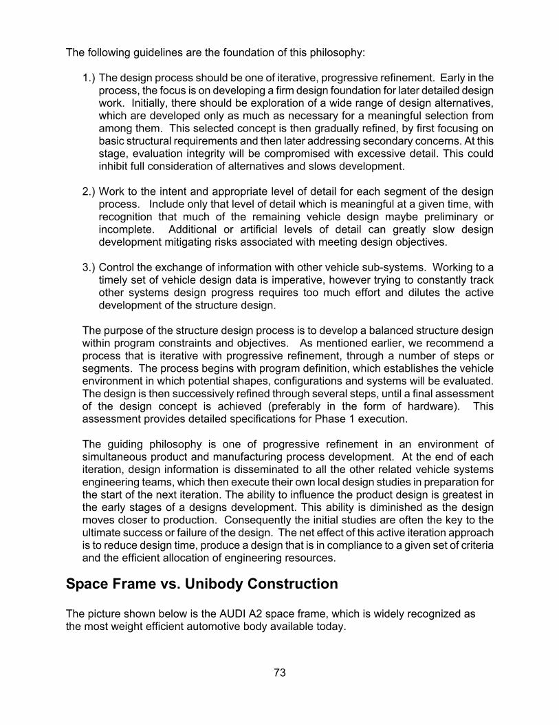
The following guidelines are the foundation of this philosophy:
1.) The design process should be one of iterative, progressive refinement. Early in the process, the focus is on developing a firm design foundation for later detailed design work. Initially, there should be exploration of a wide range of design alternatives, which are developed only as much as necessary for a meaningful selection from among them. This selected concept is then gradually refined, by first focusing on basic structural requirements and then later addressing secondary concerns. At this stage, evaluation integrity will be compromised with excessive detail. This could inhibit full consideration of alternatives and slows development.
2.) Work to the intent and appropriate level of detail for each segment of the design
process. Include only that level of detail which is meaningful at a given time, with recognition that much of the remaining vehicle design maybe preliminary or incomplete. Additional or artificial levels of detail can greatly slow design development mitigating risks associated with meeting design objectives.
3.) Control the exchange of information with other vehicle sub-systems. Working to a
timely set of vehicle design data is imperative, however trying to constantly track other systems design progress requires too much effort and dilutes the active development of the structure design.
The purpose of the structure design process is to develop a balanced structure design within program constraints and objectives. As mentioned earlier, we recommend a process that is iterative with progressive refinement, through a number of steps or segments. The process begins with program definition, which establishes the vehicle environment in which potential shapes, configurations and systems will be evaluated. The design is then successively refined through several steps, until a final assessment of the design concept is achieved (preferably in the form of hardware). This assessment provides detailed specifications for Phase 1 execution. The guiding philosophy is one of progressive refinement in an environment of simultaneous product and manufacturing process development. At the end of each iteration, design information is disseminated to all the other related vehicle systems engineering teams, which then execute their own local design studies in preparation for the start of the next iteration. The ability to influence the product design is greatest in the early stages of a designs development. This ability is diminished as the design moves closer to production. Consequently the initial studies are often the key to the ultimate success or failure of the design. The net effect of this active iteration approach is to reduce design time, produce a design that is in compliance to a given set of criteria and the efficient allocation of engineering resources.
Space Frame vs. Unibody Construction The picture shown below is the AUDI A2 space frame, which is widely recognized as the most weight efficient automotive body available today.
73

AUDI A2 Space Frame If we took a typical automobile body with carbon steel unibody construction at a weight of 1000lbs, to deliver the same performance with an aluminum space frame, the body would weigh approximately 650lbs. A space frame body of stainless steel with the same level of performance would weigh approximately 600lbs!
Chart courtesy of Jeff Dieffenbach, “The Inevitable Domination of the Reduced Mass Space frame?”
74

Summary Of Structural Automotive Approaches
Functional Area Automotive
Approach / Feature / Material
New / Automotive Processing Technology
Airframe
Door > Waterproof > Quiet > Doors off build
Structure > Dimensionally Accurate > Strong > Light > Interchangeable
> Weld Bonding > Tailor Welded Blanks > Thixotropic > Formed Sheet Metal > Gas Assisted Injection Molding
Hinges & Latches > C.O.T.S. > Thixotropic Forging Trim > Sound Deadening > E.A.R., 3M Seals > Bulb seals
Fuselage > Designed to contribute lift to airplane
Radome > SMC
Forward Structure > Crashworthy – designed to absorb energy > integral structure for nose gear > two piece
> Weld Bonding > Tailor Welded Blanks > Laser Welded > Friction Stir Welded > Formed Sheet Metal > Hydro formed Sheet > Carbon Foam
Cockpit & Passenger Area (from forward to rear bulkhead)
> Crashworthy – designed to absorb energy > Steel - inner & outer construction > Alum. - Space frame with panels
> Weld Bonding > Tailor Welded Blanks > Laser Welded > Friction Stir Welded > Formed Sheet Metal > Hydro formed Sheet > Thixotropic Forging > Swedged Aluminum
Engine Mount > Cast Aluminum > Thixotropic Forging
Tail > Steel - inner & outer construction > Alum. - Space frame with panels
> Weld Bonding > Tailor Welded Blanks > Laser Welded > Friction Stir Welded > Formed Sheet Metal > Hydro formed Sheet > Thixotropic Forging
75

Functional Area Automotive
Approach / Feature / Material
New / Automotive Processing Technology
Airframe cont’d
Wing
Spar(s) - load carrying members
> Steel - corrugated, TWB > Alum. - forged "C" spar, welded, foamed Alum or Carbon
> Weld Bonding > Tailor Welded Blanks > Laser Welded > Friction Stir Welded > Formed Sheet Metal > Hydro formed Tube w/ foamed alum. Or carbon > Swedged Aluminum > Pultruded composite
Skin > Large panels
> Weld Bonding > Tailor Welded Blanks > Laser Welded > Friction Stir Welded > Formed Sheet Metal > Hydro formed Sheet > Carbon Foam
Landing Gear Main & Nose > Thixotropic Forging Doors > Weld Bond, Hydro sheet
Actuation > Electro mechanical > Artificial muscle – charged plastic > Insert Casting
Control Surfaces
Ailerons, Flaps, Spoilers, Tail
> Composite pultrusion > Thixotropic Molding > Insert Moldings
Windows Front & Side > Encapsulated glass
76
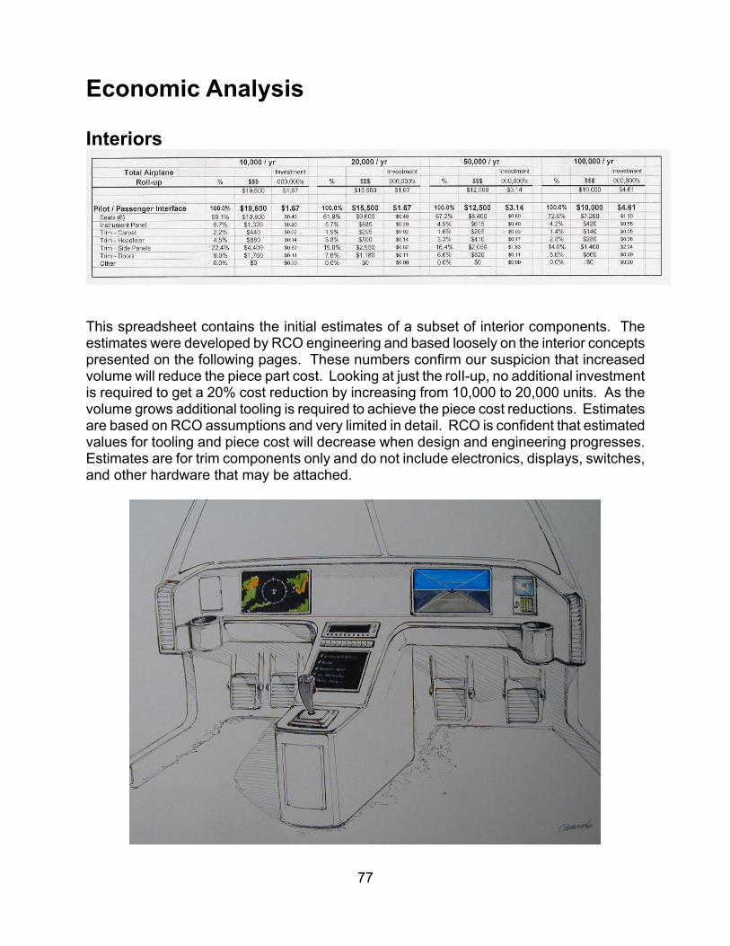
Economic Analysis Interiors
This spreadsheet contains the initial estimates of a subset of interior components. The estimates were developed by RCO engineering and based loosely on the interior concepts presented on the following pages. These numbers confirm our suspicion that increased volume will reduce the piece part cost. Looking at just the rolI-up, no additional investment is required to get a 20% cost reduction by increasing from 10,000 to 20,000 units. As the volume grows additional tooling is required to achieve the piece cost reductions. Estimates are based on RCO assumptions and very limited in detail. RCO is confident that estimated values for tooling and piece cost will decrease when design and engineering progresses. Estimates are for trim components only and do not include electronics, displays, switches, and other hardware that may be attached.
77
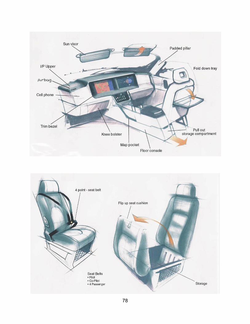
78

79

80
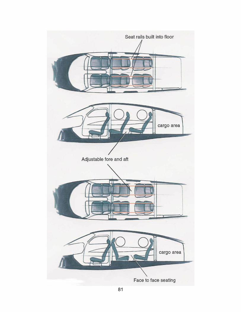
81

Conclusions
• Design is the critical driver of manufacturing costs and quality. Conventional aircraft approaches won’t deliver the paradigm shift. Lean Design™ will; by improving quality 1400 times higher and at 10 percent of the cost of a traditional GA aircraft design and manufacturing process.
• SATS needs a revolution not evolution. Implement the Six Sigma Methodology
across the SATS organization. Reducing complexity, parts and steps in the overall process will bring the SATS product up to an estimated 5.5 Sigma level from the baseline of 3.2 sigma (average for the commercial aircraft industry).
• Customer convenience technologies developed for automobiles can be transferred
to GA Aircraft if GA can form alliances with the right supply chain.
• Cockpit architectures can share common design standards between automobiles and GA Aircraft if GA can form alliances with the right supply chain.
• Information delivery architectures can be shared between automobiles and GA
Aircraft if GA can form alliances with the right supply chain.
• SATS must provide a platform for long term progressive system cost reductions and economically viable technology enhancements if it is to be successful.
• Munro is your first choice for low cost and high quality because:
Understand Auto Industry Culture and Processes Know The Players At All Levels Deep Experience In Aircraft Manufacturing Technology Transfer Across Industries New Facilities and Capabilities for Concept Development and Program
Management
• Lean Production principles do apply to software development.
• SATS should view modularization strategically. A clean sheet product presents a unique and rich opportunity to evaluate structuring the product, process and supply chain architecture for modularity.
• Adopting automotive approaches will insure a viable business case for the SATS
plane manufacturer(s).
82

Glossary of Technologies
Weld Bonding
General Design Guidelines
• Other than material properties, design for aluminum is much the same as for steel, except that thicker aluminum gages improve wall stability & permit more effective use of larger sections.
• In a weld-bonded structure, the adhesive essentially carries all loads. Welds or
mechanical fasteners provide fixturing and peel-stoppers.
• Bonding provides a slight increase in beam stiffness (10 – 20%), but a huge increase in joint stiffness (200%) in peel.
• Typical mass reductions with bond-welded aluminum are 45-50% for stiffness-
limited applications & 30 –40% for strength-limited applications, even with comparable member packaging.
• The typical hierarchy of design constraints for weld bonded aluminum GA aircraft
structure is:
a) Fatigue life of critical components: 50,000 – 75,000 hours life expectancy
b) Ultimate Strength c) Stiffness d) Crush Properties
83
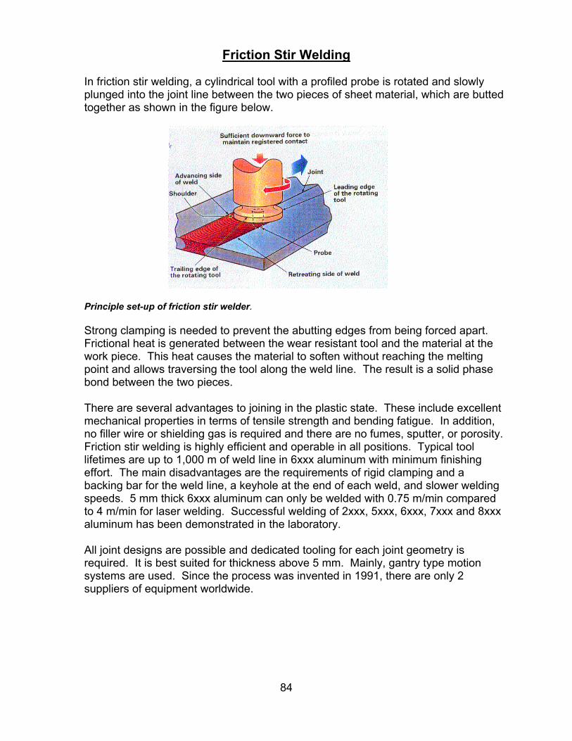
Friction Stir Welding
In friction stir welding, a cylindrical tool with a profiled probe is rotated and slowly plunged into the joint line between the two pieces of sheet material, which are butted together as shown in the figure below.
Principle set-up of friction stir welder. Strong clamping is needed to prevent the abutting edges from being forced apart. Frictional heat is generated between the wear resistant tool and the material at the work piece. This heat causes the material to soften without reaching the melting point and allows traversing the tool along the weld line. The result is a solid phase bond between the two pieces. There are several advantages to joining in the plastic state. These include excellent mechanical properties in terms of tensile strength and bending fatigue. In addition, no filler wire or shielding gas is required and there are no fumes, sputter, or porosity. Friction stir welding is highly efficient and operable in all positions. Typical tool lifetimes are up to 1,000 m of weld line in 6xxx aluminum with minimum finishing effort. The main disadvantages are the requirements of rigid clamping and a backing bar for the weld line, a keyhole at the end of each weld, and slower welding speeds. 5 mm thick 6xxx aluminum can only be welded with 0.75 m/min compared to 4 m/min for laser welding. Successful welding of 2xxx, 5xxx, 6xxx, 7xxx and 8xxx aluminum has been demonstrated in the laboratory. All joint designs are possible and dedicated tooling for each joint geometry is required. It is best suited for thickness above 5 mm. Mainly, gantry type motion systems are used. Since the process was invented in 1991, there are only 2 suppliers of equipment worldwide.
84

Laser Welding / Blanking / Trimming & Tailor Welded Blanks
85
Laser Types Lasers have advanced significantly over the past 40 years and have been established as a reliable tool in production across the industries. Driven by numerous government sponsored programs, particularly in Europe, a strong market trend emerged in the early nineties in the automotive industry. The proven technology of high power CO2 lasers and the availability of high power Nd: YAG lasers paved the way for lasers to be used as a flexible, non-contact and reliable tool in production. CO2 lasers, using CO2 gas as the active medium, emit laser light at 10.6 um and deliver output powers of up to 40 kW and higher. Reflective mirrors in a clean, purged beam delivery from the laser to the processing optic guide the light. Typical machines are 3 or 5 axis gantry type systems used mainly for laser cutting, but also for laser welding. Proven technology, moderate investment costs, and low operational costs are the motivation for the widespread use, beyond the job shops, of this type of equipment. The major automotive applications are the welding of gears to shafts in the transmission and the welding of tailored blanks. If preventive maintenance is properly done, system uptimes reach above 90%. Nd: YAG lasers use a solid-state crystal as the active medium, emit light at 1.06 um and deliver output power up to 4kW. The light is commonly guided through a fiber optic cable from the laser to the processing optic. Fiber lengths can reach more than 50 m and are far more flexible than the beam delivery of a CO2 laser. The investment costs and running costs are higher compared to the CO2 laser. However, less power is required to weld the same joint using an Nd: YAG as opposed to a CO2 laser. This results in nearly the same investment cost for both types of lasers to achieve the same welding speed. The major applications of Nd: YAG lasers are cutting of hydro formed tubes and welding of the body-in-white, e.g. the roof to the side panel. Both applications have the processing optic mounted to the end of a robot. Uptimes of more than 98% are reported in 3 shift operations. The choice of a laser for a specific application depends on numerous criteria, such as the type of material, joint or cut geometry, work cell layout, demand of flexibility and numerous other factors. Generally speaking, a trend toward the Nd: YAG laser has been observed in North America over the past five years. The Nd: YAG laser has a shorter wavelength and the energy is more easily absorbed by the material, making it a good tool for welding aluminum. It clearly offers a more stable process than the CO2 laser. Diode pumped Nd: YAG lasers and high power diode lasers (HPDL) are commonly seen as the next generation of lasers. Using HPDL rather than conventional flash lamps for pumping Nd: YAG laser crystals results in higher beam quality, nearly twice that of flash lamp pumping. This, in turn, yields a smaller spot size that results in higher processing speeds or larger stand offs, keeping the processing optic free of contamination from the weld or cut sputter. The wall plug efficiency reaches about 20%, the second highest among all lasers. In addition, HPDL run virtually maintenance-free for more than 10,000 hours, whereas flash lamps must be

changed about every 1,000 hours. Diode pumped Nd: YAG lasers are just emerging and their reliability in production must still be proven. The first pilot installations in industry with several kWs of output power occurred just recently in 1999. High power diode lasers are also used directly for materials processing rather than for pumping Nd: YAG crystals. The advantages are: the very compact and rigid design, 4 kW’s of power delivered from an enclosure the size of a shoe box, the highest wall plug efficiency among all lasers (about 30%) and the low cost of ownership. Furthermore, the investment costs, which are currently quite high, are anticipated to decrease by a factor of three over the next 3 years and the MTTF is expected to double to 20,000 hours within the same timeframe. The current drawback is the limited beam quality, which allows efficient heat conduction welding, but only very slow deep penetration welding and no efficient cutting. This technology is in its infancy, but the innovation created by the market pull is very high. Improved beam quality, lower costs and compact size will drive the HPDL to wide spread use in production within the next 3 to 5 years. The main characteristic features of CO2, Nd: YAG and high power diode lasers are summarized in the table below. The numbers given for the operational and investment costs are trend indicators and vary among suppliers and specific application.
CO2 Nd: YAG Diode Laser Active media Gas mixture Solid state
crystal Semiconductor
Wavelength 10.6 um 1.06 um 0.8 – 1.0 um Wall plug efficiency
10% 3% 30%
Typical power 8 kW (up to 40 kW) 4 kW 2 kW to 4 kW Guiding of laser light
Bending mirrors covered in clean, purged beam delivery
Fiber optic cable
Fiber optic cable, Free space
Typical operational cost
10 $/hr (for 8 kW)
20 $/hr (for 4 kW)
15 $/hr (for 4 kW)
Typical investment cost
$ 400,000 (for 6 kW)
$ 500,000 (for 4 kW)
$ 300,000 (for 4 kW)
Table 1: Typical characteristics of CO2, Nd: YAG and HPDL and indication of operational and investment costs.
Laser Welding of Aluminum Laser welding of aluminum presents far more challenges than laser welding of steel. The high reflectivity, the low viscosity of molten material, the high heat conductivity and the plasma shielding effect of aluminum require lasers with high beam quality and the shortest possible wavelength. Nd: YAG lasers are better suited than CO2 lasers because they suffer less plasma shielding. This results in a wider process parameter window for welding aluminum with an Nd: YAG, as opposed to a CO2 laser. An extensive study on laser welding of aluminum tailored blanks proves this, as shown in figure 1.
86

0
1
2
3
4
0 2 4 6 8 10 12 1Weld Speed [ m/min ]
Plat
e Th
ickn
ess
[ m
m ]
Nd:YAG3 kW
limited repeatability
CO24.6 kW
0
1
2
3
4
0 2 4 6 8 10 12 1Weld Speed [ m/min ]
Plat
e Th
ickn
ess
[ m
m ]
Nd:YAG3 kW
limited repeatability
CO24.6 kW
44
Figure 1: Process parameter window for laser welding of aluminum tailored blanks. A 3 kW Nd: YAG laser from Haas and a 6 kW CO2 laser from Rofin Sinar were used to weld 1mm, 2 mm and 3 mm thick tailored blanks of all possible configurations. The low viscosity and the high thermal conductivity of aluminum necessitate high processing speeds, in excess of 6 to 8m/min. Nd: YAG and CO2 lasers are currently capable of the higher speeds in terms of power and spot size, but the challenge remains in the motion system to accurately follow the weld line and handle the high accuracies required at the edges. Robots can manage high speeds and high accelerations, but they are normally not as accurate as necessary. 5 axis gantry type machines can handle the accuracy and the speed, but are limited in accelerations to 0.5 g to 1 g. Straight weld lines are easy to handle, but 3 dimensional weld lines create problems of accuracy in positioning the laser beam. Trepanning configurations in combination with seam tracking devices are a viable approach to handle 3-dimensional configurations. This is described in more detail in paragraph 1.3 along with the requirements for part fit-up. The welding process is similar for heat treatable and non-heat treatable alloys. Extensive studies on welding tailored blanks using 5754 and 6061 were undertaken and it was found that the parameter settings are a bit more forgiving for 6061. Less metal evaporation due to the significantly lower magnesium content reduces plasma fluctuations and improves weldability of 6061 versus 5754. However, solidification cracking occurred in the coarse-grained weld material at high welding speeds. Some liquidation cracking also occurred in the heat affected base material adjacent to the fusion boundary. Shielding gas settings are not sensitive when using an Nd: YAG, e.g. if speeds are reaching beyond 8 m/min. Pure Argon, pure Helium or a mixture of both can be used 6061 exhibited significant solidification cracking and, to a minor extent, liquidation
87

cracking. Solidification cracking diminished as the welding speed decreased due to the lower cooling rate. By adding 4047 filler wire, both types of cracking were avoided. Summarily, keyhole welding delivers high quality welds for heat treatable and non-heat treatable alloys. Lasers have proven their reliability in many production applications with very high uptimes. The motion system, as opposed to the laser itself, limits the processing speeds to accurately follow 3-dimensional weld lines. Filler wire or a laser combined with MIG has proven to be useful in controlling metallurgy for better weld integrity and longer fatigue (see paragraph 1.3). However, higher costs and increased maintenance are definite considerations. Heat conduction welding does not create a keyhole-like deep penetration weld. The laser heats the material to the melting point to achieve the joint. Heat conduction welding is very clean and does not create any sputter. Welding speeds are 10% to 15% less than for keyhole welding for thin sheet material up to 2 mm thickness. Heat conduction welding might be a viable solution for fillet and butt joints, but not for overlap joints. In addition, if adhesives are involved, the heat conduction welding mode might be preferable since it allows some time for the adhesive to evaporate. This ensures that the weld nugget will not contain imperfections or voids. The joint design must allow for evaporation. Fillet, T-, and butt joints are suitable, while overlap joints are limited. Wire feeding is another possibility for controlling the metallurgy in the nugget. Recently undertaken investigations will reveal more details on the toughness and fatigue of those welds. High power diode lasers available today are a very cost effective laser to be used for this type of joining.
88
Hybrid Processes As mentioned in paragraph 1.2, adding additional material might be required to improve the weld integrity, toughness and fatigue characteristics. Also, additional material might be required in the melt pool to fill gaps resulting from poor part fit-up. Cold wire feed and lasers combined with MIG are proven approaches that have widespread use in industry. Cold wire feed is based on feeding wire, typically 0.9 mm diameter, directly into the melt pool to be heated by the laser beam. The positioning of the wire feed with regard to the laser beam must be very accurate, which is especially challenging for 3-dimensional weld lines. Mainly silicon rich wires, such as 4047, are added to avoid hot cracking and/or solidification cracking as observed in 6xxx series aluminum. Wire feeding is not very appropriate to close gaps in the parts to be joined. A great deal of wire is needed and, therefore, consumes too much of the expensive laser energy. Wire feeding can be done for keyhole and heat conduction welding. Push–pull systems with a heat controlled wire cabinet are commonly used, i.e. on 5 axis machines with a large working envelope. Typical pricing is in the range of $35K. Another method is the use of a laser beam in combination with a MIG welder. This approach merges the high welding speeds of a laser with the gap bridging and metallurgical modification capabilities of the GMAW. Monolithic devices steering the

laser beam and the torch at the same place are available for CO2 and Nd: YAG lasers as shown in figure 2. This makes 3-dimensional applications very feasible. The price for the equipment is in the range of $ 50K. Both methods make the set-up more complex and bulky, but have already been installed in high volume production. Audi is using the laser with cold wire feed for welding the A2model, and laser plus MIG for welding structural components of the
A8. Figure 2: Monolithic laser plus MIG end effector as used for a CO2 laser. The laser beam and the plasma torch are steered to the same spot. Source: Fraunhofer Center Laser Technology. The gap bridging capabilities of the laser plus MIG approach to weld mild steel with a high power CO2 laser is demonstrated in figure 3. Fatigue-testing results of different welding methods are shown in figure 4.
89

Figure 3: Gap bridging capability of the laser plus MIG welding process. Between 8 kW and 10 kW of CO2 laser power was used and feed rates reached 5 m/min. Source: Fraunhofer Center for Laser Technology.
Figure 4: Fatigue testing of different welding methods. Source: Fraunhofer ILT Weld strength testing has been done on mild steel coupons to compare resistance spot welding with laser welding, either as stitch welds or as continuous welds. In the case of laser stitch welding, the weld length was 12.5 mm and 25 mm. For continuous welding, the width of the weld nugget was varied from 0.8 mm to 1.5 mm. Hardness profiles were measured and tensile and fatigue tests were performed. The results are shown in figure 5. Laser welding always revealed higher tensile strength and better fatigue characteristics over spot welding. In the case of continuous welding, the seam width had a minor impact. For stitch welding the length of the stitch is an important parameter. A rule of thumb for the automotive
90

industry welding of steel is that a 15 mm long stitch weld behaves very similar to a spot weld. Apparently, those results must be double-checked for aluminum, but may serve as a guideline for the initial phase.
Figure 5: Comparison of spot welding with laser welding. Laser welding was done in stitches with continuous variation of the stitch length and the width of the continuous seam. It was found that laser welding was always superior to spot welding in terms of tensile strength and fatigue testing. Source Thyssen Laser Technik Manufacturing Issues Properly maintained CO2, Nd: YAG laser systems, and HPDL’s all demonstrate very high uptimes, in the range of 95% to 98%. Most failures in production arise from the lack of trained operators and engineers to provide correct preventive maintenance and simple trouble shooting. Both result in unacceptable downtime of the production system. Extensive training, part design, handling, and laser safety procedures must also be undertaken. Laser suppliers, system integrators and process development companies have identified these needs and are combining their efforts to provide enough skilled labor to correctly design and manufacture products. In the design phase, the joint design must be carefully considered to fulfill the structural requirements and to allow for efficient laser welding. In addition to weld toughness and fatigue, the part fit-up must be ensured with all the stacked up tolerances of tools and parts. Typically, a gap of less than 10% of the depth of the weld nugget is required. Proper part and tooling design, as well as special fixtures must be considered. Roof welding in the automotive industry presents a good case study. The roof and body side both exhibit large tolerances. Additionally, the strength is insufficient without supporting structures and zinc coating creates irregular blowouts in the weld line. On the other hand, the laser requires access from only one side and can weld more than two materials in an overlap geometry. Appropriate strength is achieved by attaching hollow sections underneath the roof ditch. This results in a 3 layer joint with one-sided access. Proper tolerances are achieved by independently indexing the body side and the roof panel in their tooling. Also the joint design, an overlap
91

joint with a specific width, can accommodate tolerances higher than the stacked up tolerances of the individual parts. Proper fit-up in production is achieved by squeezing rollers mounted to the end of the robot, forcing the 2 or 3 layers of sheet metal closely together. Full penetration welding and special process conditions allow for out gassing of the zinc to result in homogenous weld integrity. The laser beam must be positioned properly to the work piece and must accurately follow the weld line. Vision systems are used to avoid problems in production caused by mechanical tolerances of the parts or the motion system. The so-called seam tracker device automatically positions the laser beam accurately to the weld line. Depending on the quality standards, on-line quality monitoring devices may also be needed. There are several commercially available systems, but experience has shown that there is no one system suitable for all applications. Exemplary Applications and Trends The entire automotive industry is focused on developing lightweight and more fuel-efficient cars. Sports cars built in low volume are used as platforms to test new technologies. There is also an increasing amount of hang-on parts for high volume cars, such as trunk lids, hoods and doors. These parts are stamped from a single sheet and do not involve any joining, except gluing of hemmed joints. Audi is leading the industry with its all aluminum cars: the high-end A8 model and the smaller A2 model. The latter is scheduled to run in high quantities. The space frame concept encompasses 35 m of laser welding, mostly augmented with filler. The A8 utilizes laser welding of the steering column (figure 6).
Figure 6: Laser welding of the front support of the Audi A8 using a CO2 laser
92

Window spacers welded with up to 200 m/min or complex shaped profiles for light weight structural components are typical high volume applications. Radiators for racecars and, more recently, radiators for production of high volume cars also employ laser welding due to the controlled heat input and metallurgy in the weld nugget, as well as the high processing speeds. Motivated by material cost savings, manufacturers of tailored blanks are starting to produce tailored blanks using aluminum. Steel tailored blanks have reached an annual market volume of well over $ 130 million at the end of the nineties – a surprising fact, looking back at the implementation of this technology in the late eighties. The major suppliers of tailored blanks have meanwhile welded enough material to stretch more than once around the earth! Another successful application is the welding of wave-guides made from aluminum. The old design used wide flanges and the lid was bolted to the housing. The laser design eliminates all the flanges. The lid was cut accurately to the housing with a laser and a hermetic butt joint was used to close up the channel. The housing is made from 6xxx series aluminum and the lid is made from 4xxx series aluminum to avoid hot and solidification cracking during laser welding. A sample part is shown in figure 7. The assembly process was dramatically shortened, additional labor was eliminated, and parts were consolidated from more than 10, down to 2.
Figure 7: Welding of satellite wave-guides. The housing, made from 6xxx aluminum is machined and closed with a lid made from 4xxx series aluminum. The lid is laser cut for a slip fit. All flanges were eliminated and the assembly process was simplified and shortened. Another application involves the floor panel of the Freightliner truck cabin. The blanks are laser welded to the structure using an Nd: YAG with filler wire to replace riveting. This application has been in production since 1998. The trend in joining aluminum in the automotive industry is moving away from riveting to using adhesives or laser welding with filler wire or MIG. The move is happening slowly due to the typical adaptation barriers we see for new technologies.
93
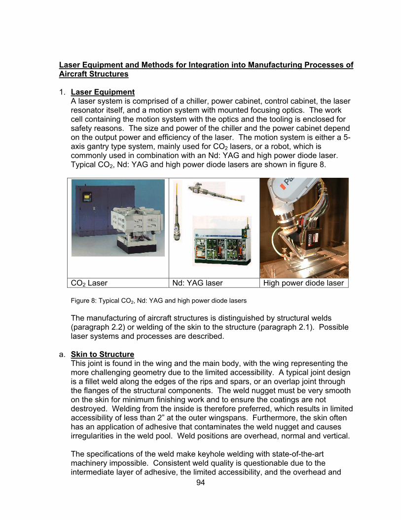
Laser Equipment and Methods for Integration into Manufacturing Processes of Aircraft Structures 1. Laser Equipment
A laser system is comprised of a chiller, power cabinet, control cabinet, the laser resonator itself, and a motion system with mounted focusing optics. The work cell containing the motion system with the optics and the tooling is enclosed for safety reasons. The size and power of the chiller and the power cabinet depend on the output power and efficiency of the laser. The motion system is either a 5-axis gantry type system, mainly used for CO2 lasers, or a robot, which is commonly used in combination with an Nd: YAG and high power diode laser. Typical CO2, Nd: YAG and high power diode lasers are shown in figure 8.
CO2 Laser Nd: YAG laser High power diode laser
Figure 8: Typical CO2, Nd: YAG and high power diode lasers The manufacturing of aircraft structures is distinguished by structural welds (paragraph 2.2) or welding of the skin to the structure (paragraph 2.1). Possible laser systems and processes are described.
94
a. Skin to Structure This joint is found in the wing and the main body, with the wing representing the more challenging geometry due to the limited accessibility. A typical joint design is a fillet weld along the edges of the rips and spars, or an overlap joint through the flanges of the structural components. The weld nugget must be very smooth on the skin for minimum finishing work and to ensure the coatings are not destroyed. Welding from the inside is therefore preferred, which results in limited accessibility of less than 2” at the outer wingspans. Furthermore, the skin often has an application of adhesive that contaminates the weld nugget and causes irregularities in the weld pool. Weld positions are overhead, normal and vertical. The specifications of the weld make keyhole welding with state-of-the-art machinery impossible. Consistent weld quality is questionable due to the intermediate layer of adhesive, the limited accessibility, and the overhead and

vertical weld positions. Heat conduction welding along the edge of the structural components is more appropriate for the following reasons. First, the joint design and the process will allow for out gassing of the adhesive prior to accomplishing the weld. Only a small area of adhesive will be removed so that the redundancy of gluing and welding is still secured. Fillet joints are intrinsically stronger than lap joints. Second, the spot size for heat conduction welding is larger, which reduces the seam tracking effort. Third, no weld sputter will occur, which allows for higher miniaturization of the focusing optic to reach into the limited accessibility areas. A system might contain a fiber coupled Nd: YAG or a high power diode laser with 2 kW to 4 kW output power, depending on throughput specifications and joint geometry. A miniaturized welding optic can be mounted to the end of a special robot. Seam tracking by vision control or mechanical means combined with a quality-monitoring device can be used for quality assurance purposes.
b. Structural Components Typical joint geometries include: - over lap for joining rips to spars, - butt joints for joining rips to spars - butt joints for joining (hydro-formed) tubes to spars - T-joint for making the spars to eliminate intensive machining Generally speaking, all of the joints have been done in 6xxx series, 5xxx series and mixtures of both alloys. Titanium, magnesium, steel and steel to aluminum also produced very good results. T-joints result in the highest strength compared to the other two joint geometries and are able to be welded from one side only or simultaneously from both sides. A gantry type system or a robot with Nd: YAG or CO2 laser plus filler wire are typical examples of systems. If the fit-up is very poor or the material is thicker than 10 mm, a laser plus MIG would be preferable. Mechanical seam tracking and on-line quality monitoring is recommended. Butt joints and overlap joints are well known and can be done in almost any configuration. The laser and the motion system are selected based on the specific application.
95
2. Laser Welding of Tubes for Hydro forming High frequency welding is routinely used for the welding of steel tubes. Very high speeds (up to several 100 m/min) and medium investment costs are the main rationale. However, problems occur with oxidation in the weld zone that lead to brittleness and possible cracking during forming. A post weld operation is also needed to remove the burr on the OD and ID of the tube. Based on these facts, almost all stainless steel tubing is currently welded with lasers. Also, for mild steel there is a trend toward investigating in more detail the technical and economic feasibility of laser welding over high frequency welding. 6xxx series aluminum tubes are extruded using state-of-the-art technology. 5xxx series aluminum tubes cannot be extruded cost effectively due to the low silicon

content. In this case, longitudinal seam welding with lasers is a technical and economically viable alternative. Laser welding offers excellent quality with speeds up to 20-30 m/min on conventional tube mills. The heat-affected zone is much smaller (compared to MIG) and no post processing is needed. Hydro-formed tubes can eliminate many parts to result in leaner manufacturing processes and decreased inventory by part consolidation.
3. Laser Welding of Aircraft Body-in-White This field is wide open with many different possibilities. Typically, all four of the various joint designs: overlap, butt, fillet and T-joints are found. It is a matter of closing the loop between design and manufacturing to come up with the best solution.
4. Tailor Welded Blanks The major appeal of tailored blanks is the increased performance of the part, together with weight reduction and part consolidation. Tailored blanks put the reinforcements where they are needed by welding together two or more metal blanks of different grades or thickness. Laser welding is employed due to the strict quality requirements and high throughputs required for a quick return of invest. Alternatively, tailored blanks can also be mash seam welded. Many different cost models have been developed but they are usually supplier specific, making generalizations regarding cost justifications very difficult. A good general model was developed by ULSAB. It lacks detail, but is a good first study. Linear blanks comprise more than 80% of the market, with non-straight and non-linear blanks making up the remainder. Typical linear tailored blanks are door inners manufactured in the highest volumes. Body sides encompass multiple linear, but no straight weld lines, welding up to 4 or 5 blanks together. The first non-linear designs are being used for lift gates. Examples of these tailored blanks are shown in figure 9. The benefit of increased design flexibility is offset by the complexity of the forming die.
Body side Lift gate Door inner
Figure 9: Examples of linear, non-straight and non-linear tailored blanks. Door inners, a linear tailored blank, comprise the biggest market share. Body sides, like those used for the Jeep, are made from 4 or 5 blanks containing multiple linear, but non-straight weld lines. Non-linear tailored blanks are suitable for lift gates.
96

5. Laser Welding Successes
The benefits of employing lasers in production are demonstrated by increased performance of the part. This intangible benefit makes it difficult to attach a number to the bottom line. To obtain the greatest benefits, the product must be designed around the laser to result in leaner assembly processes, higher strength, or less finishing work, to name a few of the advantages. Some generic benefits of laser technology are the precise heat input and high feed rates at high and consistent quality with low distortion and reduced requirements for finishing work. This leads to higher quality products and fewer rejected parts that require less labor during the assembly and finishing process. The increased joint strength and the one sided access allow for new joint designs that potentially result in higher performance, less tooling effort and materials savings. Food cans, for example, are manufactured by press fitting the lid over the deep drawn body of the can. The press fit requires a certain flange width. By using lasers, the flange width can be reduced by some tens of a millimeter. The resulting material savings together with the high throughput justify the investment in laser equipment. Nearly all-European car manufacturers have implemented laser welding for the roof of the car body. Currently, Volkswagen is using more than 80 fiber coupled 4 kW Nd: YAG lasers in their production plants. Uptimes in excess of 98% are reported; but cost justifications are not yet in the public domain. The benefit is the increased stiffness and the resultant improved passenger safety. Easier design, part consolidation and weight savings have also been achieved. Volkswagen has even been able to eliminate the sealing operation by proper joint design doing a fillet weld. Another typical application is the welding of transmission components, such as the gear to the shaft. Car manufacturers worldwide are using laser welding to join a case hardened gear to a low carbon shaft. High throughputs, specific joint design, limited accessibility and strict quality requirements are driving the use of lasers. Tailored blanks are a very successful example to support the use of laser welding. In the past decade, the market for tailored blanks has grown to more than $ 130 million, which is probably the best proof of its technical and economic viability. Airbus has developed laser welding of structural aluminum components and will apply this process for the first time in 2001 to the new Airbus 318. The application uses two 4 kW Nd: YAG lasers to join stringers to the fuselage of the airplane. The laser process and the welds have successfully passed all testing and acceptance procedures required for aircrafts. Compared to the conventional riveting process, cost savings of 20% and weight savings of 10% are achieved by using the more efficient laser welding process.
97

98
6. Laser System Costs
Indications for costs are given in table 1 for a typical laser. The cost for the peripheral equipment is strongly dependent on the working envelope, clearance and many other issues. Without knowing the specific applications, only very rough indications can be given.
Typical costs for accessories are:
- Miniaturized welding optic: $ 25,000 - fiber optic cable 30 m long: $ 15,000 - wire feed system: $ 35,000 - laser plus MIG: $ 50,000 - seam tracking device: $ 60,000 - on line quality monitoring device: $ 45,000
Typical costs for the motion system are:
- robot with far reach: $120,000 - 5 axis gantry type system $ 400,000 plus, depending on the working range
Typical laser costs including the chiller are:
- 4 kW Nd: YAG: $ 500,000 - 4 kW Diode laser $ 300,000
Additional costs might occur from enclosure, safety devices and foundations.
Steel:
0
5 0
1 0 0
1 5 0
2 0 0
2 5 0
3 0 0
3 5 0
4 0 0
S tr e n g th /W e ig h t fo r V a r io u s M a te r ia ls
1 0 1 5 A n n .
A 7 1 5 G r .7 0 (H S L A )
4 0 9 N i
3 0 4 (a n n )
N itr o n ic 3 0 -a n n
N itr o n ic 3 0 -1 0 %
N itr o n ic 3 0 -2 0 %
6 0 6 1 -T4 (A lu m . )

Material Density .2% YS U.T.S. El.-2" Modulus (E)
lb/in3 (g/cm3) ksi (Mpa) ksi (Mpa) % 106psi (Gpa)
1015 Ann. .284 (7.9) 41 (283) 56 (386) 37 30 (207)A715 Gr.70 (HSLA) .284 (7.9) 75 (517) 85 (586) 24 29 (200)
.282 (7.8) 55 (379) 69 (476) 25 29 (200)
.289 (8.0) 42 (290) 90 (620) 55 28 (193)
.285 (7.9) 54 (372) 112 (772) 55 28 (193)6061-T4 (Alum.) .098 (2.7) 21 (145) 35 (241) 22 10 (69)
Typical Material Property Comparison 409Ni (ann)304 (ann)Nitronic 30 (ann)
Stainless Steel Sheet products:
• The austenitic class (200’s and 300’s) of stainless steels is noted for excellent fabricability without unduly sacrificing properties. Elongations over 50% and exceptional toughness and weldability lend themselves to fabrication of complex geometries by any fabricating means. Some work harden quickly, which tends to make them ideal for operations requiring stretch.
• The Ferritic stainless steels are more economical (say $.75/# vs. $1/#) and can survive in many corrosive environments. In thin sections with proper knowledge, intricate shapes are possible, especially when draw is the primary mode of metal deformation. In heavier sections and at weld heat affected zones, impact toughness resistance can transition to brittle behavior at lower ambient temperatures and this can limit their application.
• Martensitic stainless steels require heat treatments to attain the very high strength levels they are known for, but the ductility is then very limited. These can be used to advantage for cutting edges, like knives, and springs.
• Duplex stainless steels are equal to or more expensive than austenitics and have properties between the austenitics and ferritics, except for annealed strengths much higher than either with good ductility. When stress corrosion cracking is a potential, these alloys are ideal and do not have the toughness problems of the ferritics.
• PH stainless steels are in two classes. Martensitic like the above with even higher strength (after a heat treatment during fabrication) and better corrosion resistance. Semi-austenitics are sold as austenitics that can be readily formed and then subsequently, with double heat treatments, be brought to extremely high strength. However, PH alloys are extremely expensive (~$2.50/#) and have found most uses in spring applications and aerospace applications, such as wing honeycomb panels (contact Aztech in Phoenix).
99

For structural uses, modified ferritic alloys like AK 409Ni and 410-03 are designed to minimize cost while minimizing the potential for toughness problems in cold weather, especially in heat affected zones. Standard ferritics can be employed when thin, unwelded or toughness is not required. Low carbon austenitics with high work hardening rates, like AK Nitronic 30, are suggested for highly formed areas where even better corrosion resistance or toughness is needed. PH alloys should be employed when heat-treating is allowable after fabricating and the high strength is sufficient to offset the high price.
Chemotropic Forging, Molding
Chemotropic metal forming is based on the principle that magnesium, aluminum, and zinc alloys become semi-solid at temperatures above 95% of melting point. Mechanical shearing of the semi-solid metal generates a chemotropic structure that allows these materials to be molded utilizing a process similar to plastic injection molding or forged. Unlike die-casting, the process does not require the handling of molten metals in separate melting and transfer systems. Unlike forging, the process does not require long processing lines and secondary machining. Chemotropically molding / forging has the mechanical properties of a forging with the cost of a casting. Advantages include less air entrapment – porosity, less solidification shrinkage, fine grain structure, heat treatable products, capable of intricate parts, near net shape.
Thixotropically MoLean Designed Automotive Seat Back
100
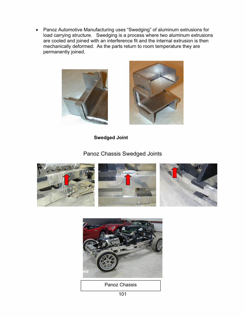
101
• Panoz Automotive Manufacturing uses “Swedging” of aluminum extrusions for
load carrying structure. Swedging is a process where two aluminum extrusions are cooled and joined with an interference fit and the internal extrusion is then mechanically deformed. As the parts return to room temperature they are permanently joined.
Swedged Joint
Panoz Chassis Swedged Joints
Panoz
Panoz Chassis

Metal Deformation Joining
• Electro-Magnetic Forming (EMF) has achieved wide acceptance for over 30 years as a proven production method on high volume assembly lines. The basic magnetic pulse principle is the same as what activates a simple electric motor. When an electric current generates a pulsed magnetic field near a suitable metal surface, a controllable pressure is created which can reshape metals without physical contact. Energy storage capacitors, a work coil and the necessary switching devices are the basic elements of EMF machines. Applications include mechanical joints for axial & torque loading. Examples include aircraft torque tubes, ducting, control rods, for Torque Loading, i.e. automotive drive shafts
Section View of a Magnetically joined Automotive Drive Shaft
Carbon Foams
Carbon foams currently are being developed for a variety of uses, including fire-resistant ship decking and bulkheads, noise and impact mitigation for aircraft, structural panels and firewalls for automobiles, lightweight personnel and vehicular armor, modular construction, and as part of spacecraft thermal management systems. CFOAM Carbon foams from Touchstone Research Laboratory are unique in their tailor able mechanical, thermal, and energy absorption properties. They can be fabricated in a variety of shapes, sizes, and densities to meet the property requirements of specific applications. These foams will not off-gas at elevated temperatures and will not support ignition. Unlike most metals and ceramics, carbon foam mechanical properties do not deteriorate with increased temperature if protected from oxidation, making carbon foams an attractive thermal protection material. Carbon foams also are tolerant to impact damage and can be repaired in-place using carbonaceous adhesives. They can be bonded easily to dissimilar materials, such as metals or PMCs, for oxidation or further impact protection.
102
Other Report Contributors
RCO Engineering, Inc.
•Established in 1973, RCO is a full service supplier providing global engineering, styling and design resources, prototype, production tooling, product build, verification to the TRANSPORTATION INDUSTRY
•Employs over 500 technical employees including engineers & CAD designers
•State of the art technology including 160 CAD stations supported by global ANX (automotive network exchange) capabilities.
•ISO 9001 Registered.
RCO Divisions
Seating & SoftTrim
Design &Engineering
Plastic Parts / Tooling
103

Seats & Trim Development
Show & Concept Vehicles
104
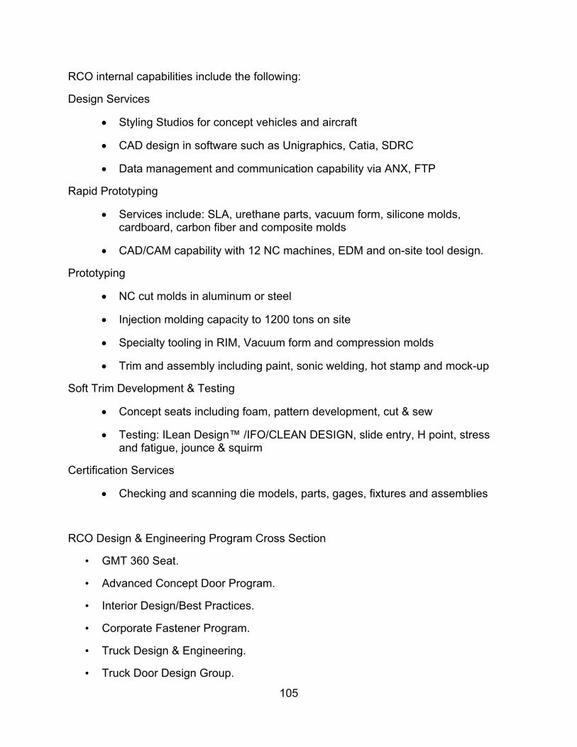
RCO internal capabilities include the following:
Design Services
• Styling Studios for concept vehicles and aircraft
• CAD design in software such as Unigraphics, Catia, SDRC
• Data management and communication capability via ANX, FTP
Rapid Prototyping
• Services include: SLA, urethane parts, vacuum form, silicone molds, cardboard, carbon fiber and composite molds
• CAD/CAM capability with 12 NC machines, EDM and on-site tool design.
Prototyping
• NC cut molds in aluminum or steel
• Injection molding capacity to 1200 tons on site
• Specialty tooling in RIM, Vacuum form and compression molds
• Trim and assembly including paint, sonic welding, hot stamp and mock-up
Soft Trim Development & Testing
• Concept seats including foam, pattern development, cut & sew
• Testing: ILean Design™ /IFO/CLEAN DESIGN, slide entry, H point, stress and fatigue, jounce & squirm
Certification Services
• Checking and scanning die models, parts, gages, fixtures and assemblies
RCO Design & Engineering Program Cross Section
• GMT 360 Seat.
• Advanced Concept Door Program.
• Interior Design/Best Practices.
• Corporate Fastener Program.
• Truck Design & Engineering.
• Truck Door Design Group.
105

• Over 100 Engineers.
• Over 200 UG Designers.
• Class A Surface Development.
• Advanced Aircraft Program.
• Complete Program Management.
• Compliant with GM Design & Engineering Practices
• Eclipse 500 Jet interior and seats
American Iron and Steel Institute For over a century, North American steel producers have left their day-to-day rivalries behind to work as partners and members of the American Iron and Steel Institute in furthering its mission to promote steel as the material of choice and to enhance the competitiveness of the North American steel industry and its member companies.
AISI's overall mission centers on common goals and a clear vision for the future:
• To provide high-quality, value-added products to a wide array of customers;
• To lead the world in innovation and technology in the production of steel;
• To produce steel in a safe and environmentally friendly manner; and
• To increase the market for North American Steel in both traditional and innovative applications.
• To assist our customers in the application of steel.
AISI is composed of producer member companies, including integrated, electric furnace, and reconstituted mills, associate member companies; which are suppliers to or customers of the industry; and affiliate member organizations, which are downstream steel producers of products such as cold rolled strip, pipe and tube, and coated sheet.
Member Company’s account for more than two-thirds of the raw steel produced in the United States, Canada, and Mexico.
Programs The Institute plays a pivotal role in the industry's ongoing renewal and in realizing its vision of the future steel industry. It engages in a wide variety of collective and collaborative activities, organized into five major areas:
106

Communications - AISI communicates the mission and strategic goals of its
members to industry and allied-industry representatives, members of the media, government officials, academia, analysts and the general public. It produces over 150 publications and brochures that provide educational, technical, promotional, and general interest information to a wide range of audiences. AISI serves as a clearinghouse of industry data and information for its members, the press and the general public.
Manufacturing and Technology - AISI pursues improvements in steel’s manufacturing competitiveness. Through a comprehensive network of technical committees, AISI facilitates the timely and efficient exchange of information on operating practices within the industry. The Institute also monitors the technical advances of competitive materials. And through its collaborative research projects, AISI brings about advances in technology which no one company could accomplish as efficiently on its own.
Market Development - AISI works closely with major customer groups to make steel the material of choice in the automotive, construction, container, appliance and other markets. A primary emphasis is to find cost competitive steel-based solutions to meet the demands of the marketplace. Through direct company involvement, programs are established in applied research, product design, codes and standards and technology transfer.
Public Policy - AISI represents its U.S. members before the U.S. Congress and the Executive Branch, promoting policies based on common sense, sound science, fair trade, and the encouragement of reinvestment, growth and creation of jobs. AISI assists its Canadian and Mexican members in coalescing public policy issues affecting the North American steel industry.
Statistics - AISI is the source of accurate statistical information on the North American steel industry. From its weekly releases on steel production and capability to its comprehensive annual statistical report, AISI serves as a catalyst for better industry decision making, sharper industry analysis and more informed government policy making.
Automotive Applications Committee The Automotive Applications Committee (AAC) is a subcommittee of the Market Development Committee of AISI and focuses on advancing the use of steel in the highly competitive automotive market.
With offices and staff located in Detroit, cooperation between the automobile and steel industries has been significant to its success. This industry cooperation resulted in the formation of the Auto/Steel Partnership, a consortium of Daimler Chrysler, Ford and General Motors and the member companies of the AAC. The Auto/Steel Partnership is now in its 14th year and has had a significant role in helping steel to maintain its share of the market. Collectively, members of the A/SP have been able to identify engineering and manufacturing problems and to develop compatible solutions. This initiative has been redirected into a more aggressive posture, that of broadening the scope in the A/SP’s programs toward light weighting issues.
107

The mission of the Automotive Applications Committee is to make flat-rolled steel the material of choice in automotive and its vision has four key goals, as follows:
Recapture Lost Business is the focus of three ongoing AAC projects and the fourth, which was launched in 2000. The three existing projects – Wheels, Closures, and Bumpers – present to auto company engineers and to the suppliers of these components the strongest arguments for returning to steel, namely affordability, manufacturability, design flexibility, and recyclability. The fourth project, fuel tanks, was launched to evaluate current conditions and to build effective steel messages designed to present solutions to perceived problems in nonmetallic fuel tanks. The expectation is to have meaningful coordinated tech transfer and communication efforts designed to effect change.
Create Best Strategic Partner to strengthen relationship between steel and automotive comes with a dedication by steel to explore possible expansion of the Auto/Steel Partnership. Now in its 14th year, A/SP steel members have proposed and worked to implement changes in the A/SP project structure so it will have a significantly greater interest in fostering the application of the light weighting technology offered by ULSAB, ULSAC, ULSAS, and ULSAB-AVC. In addition, steel members will more intensely pursue opportunities to increase the membership base of A/SP to include new American manufacturers and, perhaps, tier one and tier two suppliers. (A separate partnership program maybe initiated for the New American Manufacturers.) It is expected that the ULSAB related technologies and the work of the A/SP would interest Honda, Toyota, and other “transplant” auto manufacturers. The new IMPACT program with Ford and the US Army is a single OEM collaborative partnership wherein steel industry engineers are working together with Ford engineers to reduce by 25 percent the weight of the Ford F-Series of pickup trucks, which can then be adapted to military use.
Foster “Best Material” Perception among all audiences will be accomplished by
continuing intense communication and technology transfer activities of the AAC and A/SP, which have now reached maturity, i.e. consistent use of all effective message delivery systems. Working with the technology emerging from all AAC backed projects, the industry communications specialist’s craft strongly persuasive messages that are effectively disseminated among all audience levels. This involves close coordination among automotive sheet steel producers, the Steel Recycling Institute, the Steel Alliance and the Auto/Steel Partnership. The expectation is to see measurable change in perceptions among key automotive audiences, which will be measured by ongoing research. While much ado has been made about the growth of competing materials, steel continues to maintain its 55% share of the curb weight of the average family vehicle for the last 15-plus years. Research by the AAC has identified that aluminum growth has been in castings and not sheet products. Plastic and composite materials are still extremely expensive. However, there is still considerable interest in both materials and vigilance must be maintained.
108

Demonstrate Steel Intensive Design for Cars and Trucks is exemplified by the
work of the Ultra Light consortiums and the IMPACT project with Ford. ULSAB addresses the light weighting and performance improvement in automobiles and IMPACT will concentrate on light truck design.
The Ultra Light Steel Auto Body (ULSAB) program was formed to answer the challenge of carmakers around the world: reduce the weight of steel auto body structures while maintaining their performance and affordability. The consortium contracted Porsche Engineering Services, Inc. (PES) to provide engineering and manufacturing management for the ULSAB project and worked with PES to define the project goals. It took a two-phase approach: The concept phase encompassed a clean-sheet design of a lightweight steel auto structure; the validation phase verified the design through the manufacture of ULSAB structures. It is without question that, had steel done nothing to maintain its position in this market, the market share would now be severely reduced and declining. ULSAB -- Light Weight, High Performance, Low Cost
Begun in 1994, the ULSAB initiative was funded by a consortium of 35 of the world’s largest steel producers, including 11 from North America. It set out to show both theoretically and physically that a steel body in a family sedan could meet or exceed a wide variety of exacting performance and cost targets while maintaining the highest standards of safety.
The ULSAB structure weighs merely 203 kg (447 lbs.), up to 36 percent less than the nine mid-size sedans benchmarked in the concept phase of the study. Torsion and bending tests of the structure showed dramatic improvements over benchmark of 80 percent and 52 percent, respectively, and first body structure mode indicates a 58 percent improvement. Computer modeling also shows ULSAB satisfies mandated crash requirements, even at speeds exceeding some of the requirements.
ULSAB was manufactured and assembled using current techniques and practices including maintaining tolerances and quality standards equivalent for high volume production. The project did not use manual forming because of the desire to demonstrate clearly that ULSAB can be made right now with today's materials and technology. ULSAB employs about one-third fewer spot welds and significantly more laser welding that a conventional body structure.
In addition to reduced weight and superior performance, ULSAB would cost no more to build than typical auto body structures in its class and can even yield potential cost savings, according to economic analysis.
In a companion initiative to ULSAB, North American steel companies through AISI revealed their Light Truck Structure (LTS) study, similar to the design approach used in ULSAB. Aimed at light trucks and sport utility vehicles, LTS resulted in reduced weight, improved performance and safety and showed potential manufacturing efficiencies and cost reductions in the bargain.
Steel – A Material of the Future 109

Steel is the dominant material in auto and truck bodies today, and it will continue to be used in bodies of the future because of its strength, ease of manufacture, recyclability and relatively low cost.
ULSAB demonstrated that the steel industry can and will help its automotive partners meet the fuel economy, safety and environmental challenges that loom into the next century. The project challenges the paradigm that says that a stiffer, stronger structure must be heavier.
About 90 percent of the steel used in the ULSAB project is high-strength or ultra-high-strength steel, and about half of the mass is in tailor-welded blanks. Several key structural components were made with hydro forming processes and two important non-structural parts comprise very light weight steel sandwich material.
Some of the grades and thicknesses of steel used in ULSAB are not commonly used in auto bodies today, but all are available. Furthermore all of the ULSAB steels are recyclable.
Analyses also show ULSAB satisfies mandated crash requirements, even at speeds exceeding the requirements. In addition to reduced weight and superior performance, ULSAB costs no more to build than typical auto body structures in its class and can even yield potential cost savings, according to economic analysis.
The ULSAB project employs many techniques and processes that were unique and deemed patentable by international attorneys. The Consortium chose to make all patentable features along with other project results freely available to its customers and to the public. All intellectual property generated by ULSAB has been placed in the public domain.
ULSAB is a vivid example of the power of international, inter-industry cooperation. The cooperative efforts of design engineers, steel manufacturers, component fabricators, assembly experts and economists who worked on the project illustrate that automakers can retain the benefits of steel while realizing substantial mass reductions and increasing the performance of auto structures.
ULSAC -- Taking the Inside Out!
The global steel industry formed the Ultra Light Steel Auto Closure (ULSAC) Project to advance the state-of-the-art in lightweight, cost effective, safe and environmentally benign auto closures, and close examination of the details of the design of the competed frameless door hardware demonstrates the point.
With use of high- and ultra high-strength steels and technologies such as tailor-welded blanks, stamping and hydro forming, the ULSAC door achieved 33 percent mass savings over the average Concept Phase benchmark from a wide range of door structures. It is 42 percent lighter than the Validation Phase benchmarked average of frameless doors only, and 22 percent lighter than the lightest benchmarked unit, a framed door structure.
The validated door weighs 23.15 pounds (10.5 kg) and would cost $66.50 to manufacture in typical high-volume production (greater than 225,000 units). With no compromise to safety, the door meets or exceeds a range of performance requirements and would cost no more to build than doors in the benchmark group.
110

The design eliminates the need for a structural full door inner panel. This is partly a result of the four tubular parts that make up the basic door structure, which are high-strength workhorses for achieving necessary crash safety and structural performance at significantly reduced weight. The door structure provides an excellent example of both part and functional consolidation. The two vertical hydro-formed tubular parts eliminate the need for several reinforcements, particularly at the hinge and mirror flag attachments points. The upper and lower tubes provide stiffness and work together as side intrusion beams, simultaneously meeting both basic structural and crash energy management responsibilities.
ULSAB --AVC -- Advanced Vehicle Concepts; Steel's Answer to PNGV
The program, ULSAB-AVC, will take a holistic approach to the development of new advanced steel automotive vehicle architecture. The scope of the program is intended to go beyond the body-in-white to include closures, suspensions, engine cradle and all structural and safety relevant components.
The objective of the program is to demonstrate and communicate that the innovative use of steel in automotive applications provides a range of functional and societal benefits. These include:
• Environmental responsibility through energy and resource efficiency
• 100% recyclable with current recycling rates approaching 100%
• Safety through design and material selection
• High volume production through established and innovative manufacturing techniques
• Inherent affordability through modern manufacturing technologies
• Low cost of ownership including ease of repair
AK Steel serves the most demanding customers in the most desirable segments of the U.S. stainless flat-rolled markets. The majority of our products are sold to automobile manufacturing facilities, while others head to appliance, construction and manufacturing markets. The following customers use our steel to make their cars, trucks, mini-vans and sport-utility vehicles: BMW, Daimler-Chrysler, Ford, General Motors, Honda, Isuzu, Nissan, Toyota. AK Steel also directly serves the following clients: Frigidaire, General Electric, Maytag, and Raytheon.
111

The Fraunhofer Society is Europe’s largest contract R&D organization. It has its headquarters in Munich and decentralized research institutes across Germany that is focusing on specific technical areas. Fraunhofer serves 3000 customers annually from industry and government and had a budget of nearly $1 billion in 1999. Fraunhofer U.S.A was incorporated in 1994 in Rhode Island as a non-profit organization. It is the U.S. subsidiary of the Fraunhofer Society with headquarters in Plymouth, Michigan and research centers throughout the US. The centers perform contract research for industrial and government customers based on the expertise of their parent institutes in Germany and the requirements of industry. The Fraunhofer Center for Laser Technology (FC-LT) has a new 8,500 square foot development center housing $8 million worth of the most varied, leading edge laser equipment. The FC-LT is partnered with the Fraunhofer Institute for Laser Technology (ILT), located in Aachen, Germany. The ILT has been recognized as a world leader in the progress of laser technology for well over a decade. The ILT and the FC-LT have a combined staff of more than 250 employees dedicated to the development of new lasers and their applications. Our mission in the US is to transfer and integrate innovative laser technology into industry. The Fraunhofer Center for Laser Technology offers a comprehensive array of services that include R&D, systems design and assembly, prototyping, quality assurance, consultation, education and training for customers. Solutions are proven to be profitable and production worthy by our laser experts. We minimize your risks and you profit from our experience.
112
Sources and Methods
• 42 Volt Power: An Opportunity To Redefine The Vehicle The Hansen Report On Automotive Electronics August 2000
• Architectural Leadership In The Automotive Industry Automotive Electronics: Delivering Technology’s Promise
• Cadillac DeVille Thermal Imaging Night Vision System Human Factors in 2000: Driving, Lighting, Seating Comfort, and Harmony in Vehicle Systems
• Bill Gates: Business At The Speed of Thought 1999 Pages 372 -386 • Improving Performance In Integrated Product Development Time
Compression Technologies, June 2001 • Strategies For Surviving The Auto Interiors Supply Chain Profit Crunch
Auto Interiors, February 2001 • Lean Programming Part 1 and 2 Software Development Online, May/June
2001 • RQ-1A Global Hawk Intelligence Resource Program, July 2001 • The New Mooney Team Settles In For The Long Haul Private Pilot,
February 2000 • The Futures Not Far Away Auto Field Guide April 2001 • From The Driver’s Seat To The Flight Deck: Avionics Makers Adopt Auto
Technology Avionics Auto Impacts, June 2001 • DelphiAuto.com
113

114
NASAAERO NAUTICS
Automotive Approaches for General Aviation Aircraft
for
THE ADVANCED GENERAL AVIATION TRANSPORT EXPERIMENTS (AGATE) PROJECT
Work Package Title: WBS 7.0 SATS Planning
Reference Number: AGATE-WP7.0-99970-003-Report
Date for general release
March 2002
AGATE Alliance Association
3217 N. Armistead Ave., Suite M
Hampton, Virginia 23666-1379