Embed Size (px)
Citation preview
11-2012, Rev. 1112www.te.com© 2012 Tyco Electronics Corporation,a TE Connectivity Ltd. company.
Datasheets and product specification ac-cording to IEC 61810-1 and to be used only together with the ‘Definitions’ section.
Datasheets and product data is subject to the terms of the disclaimer and all chapters of the ‘Definitions’ section, available at http://relays.te.com/definitions
Datasheets, product data, ‘Definitions’ sec-tion, application notes and all specifications are subject to change.
1
n Suitable for voltage levels up to 450VDCn Precharge currents up to 20An Limiting break currents up to 20An Available with PCB and plug-in terminals
Typical applications DC high voltage pre-charge applications in hybrid, full battery electric vehicles and fuel-cell cars.
Contact Data Contact arrangement 1 form X (NO DM)Rated voltage 400VDCMax. switching voltage1) / power 450VDC / 9kW Limiting switching current2)
normal operation 20A on/0A off: min. 105 ops. fault break operation3) 20A on/20A off: min. 10 ops.3)4)
Initial contact voltage drop at 10A typ. 150mV, max. 300 mVOperate time at nominal voltage typ. 2.5msRelease time5) typ. 1msMechanical endurance >107 ops.1) Consult TE Connectivity for insulation compatibility with higher voltages.2) Load circuit: L/R <14µs.3) After 10 fault break operations relay must be replaced.4) Test conditions: on-time 100ms, off-time 10s. 5) Valid for recommended 250Ω suppression resistor (PCB version).Note: A low resistive suppression device in parallel to the relay coil increases the release time and reduces the lifetime due to increased erosion and / or higher risk of contact tack welding.
Coil Data Nominal voltage 12VMin./Max. energization duration max. 2s6)
Max. coil temperature 155°C6) Max. continuous activation time is limited and depends on operating conditions.
Please contact TE Connectivity for details.
Coil versions Coil Rated Operate Release Coil Rated coil code voltage voltage voltage resistance power VDC VDC7) VDC7) Ω±10% W 001 12 6.9 1.2 50 2.9 0028) 12 6.9 1.2 41.6 3.57) All values are given for coil without pre-energization, at ambient temperature +23°C.8) Coil suppression resistor already included in the relay. No additional suppression
component allowed.
Mini K HV
Automotive RelaysHigh Voltage Precharge Relays
Insulation Data1) Initial dielectric strength between open contacts 2800 VDC/1mA between contact and coil 2800 VDC/1mAInsulation resistance after 10 fault break ops. (20A) between open contacts >200MΩ between contact and coil >200MΩMax. altitude 4000mClearance / creepage acc. IEC60664-1 (2007) for over voltage category I, pollution degree 2
Other Data EU RoHS/ELV compliance compliantFlammability of plastic material acc. UL94-HBAmbient temperature range -40°C to +85°CClimatic cycling with condensation EN ISO 6988 6 cycles, storage 8/16hTemperature cycling (shock) IEC 60068-2-14, Na 10 cycles, -40/+85°C (5°C per min)Damp heat constant IEC 60068-2-3, Ca 56 days, upper air temperature 40°CDegree of protection PCB version IEC 61810 RT III – immersion cleanableCorrosive gas IEC 60068-2-42 10 days IEC 60068-2-43 10 daysWide-band noise IEC 60068-2-64 10 to 1000Hz, 30.8 m/s2 9) Shock resistance (functional) IEC 60068-2-27 (half sine) 11ms, 20g9)
Terminal type PCB and plug-in/QCWeight PCB version: approx. 17g (0.6oz) Plug-in version: approx. 39g (1.4oz)Solderability (aging 3: 4h/155°C) PCB version IEC 60068-2-20, Ta, method 1 hot dip 5s, 215°CResistance to soldering heat PCB version IEC 60068-2-20, Tb, method 1A hot dip 10s, 260°C with thermal screen Note: Parameters given in http://relays.te.com/definitions for preheating and soldering must be observed.Sealing, IEC 60068-2-17 PCB version Qc, method 2, 1min/70°CStorage conditions according IEC 6006810)
09) No change in the switching state >10µs. 10) For general storage and processing recommendations please refer to our Application
Notes and especially to Storage in the Definitions or at http://relays.te.com/appnotes/
mini_khv_collage
Coil operating range
11-2012, Rev. 1112www.te.com© 2012 Tyco Electronics Corporation,a TE Connectivity Ltd. company.
Datasheets and product specification ac-cording to IEC 61810-1 and to be used only together with the ‘Definitions’ section.
Datasheets and product data is subject to the terms of the disclaimer and all chapters of the ‘Definitions’ section, available at http://relays.te.com/definitions
Datasheets, product data, ‘Definitions’ sec-tion, application notes and all specifications are subject to change.
2
Automotive RelaysHigh Voltage Precharge Relays
Mini K HV (Continued)
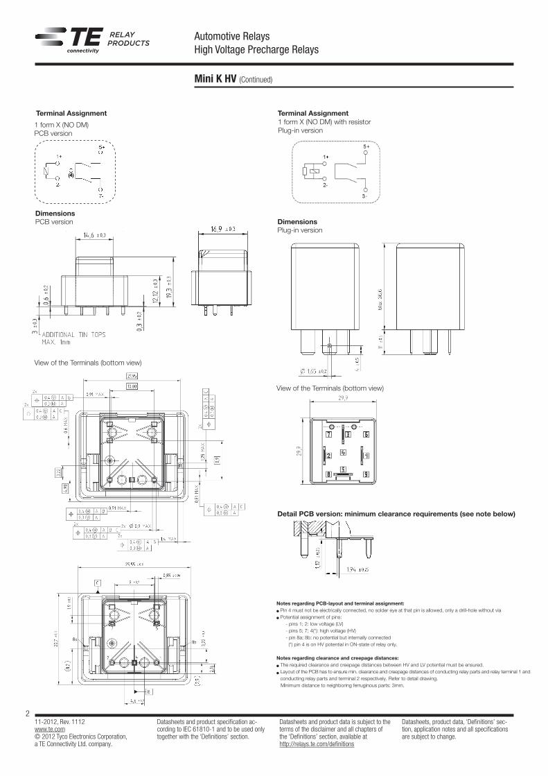
Terminal Assignment
View of the Terminals (bottom view)
DimensionsPCB version
Detail PCB version: minimum clearance requirements (see note below)
1 form X (NO DM)PCB version
Terminal Assignment
View of the Terminals (bottom view)
1 form X (NO DM) with resistor Plug-in version
+
-
DimensionsPlug-in version
Notes regarding PCB-layout and terminal assignment: Pin 4 must not be electrically connected, no solder eye at that pin is allowed, only a drill-hole without via Potential assignment of pins: - pins 1; 2: low voltage (LV)
- pins 5; 7; 4(*): high voltage (HV) - pin 8a; 8b: no potential but internally connected (*) pin 4 is on HV potential in ON-state of relay only.
Notes regarding clearance and creepage distances: The required clearance and creepage distances between HV and LV potential must be ensured. Layout of the PCB has to ensure min. clearance and creepage distances of conducting relay parts and relay terminal 1 and conducting relay parts and terminal 2 respectively. Refer to detail drawing.
Minimum distance to neighboring ferruginous parts: 3mm.
11-2012, Rev. 1112www.te.com© 2012 Tyco Electronics Corporation,a TE Connectivity Ltd. company.
Datasheets and product specification ac-cording to IEC 61810-1 and to be used only together with the ‘Definitions’ section.
Datasheets and product data is subject to the terms of the disclaimer and all chapters of the ‘Definitions’ section, available at http://relays.te.com/definitions
Datasheets, product data, ‘Definitions’ sec-tion, application notes and all specifications are subject to change.
3
Automotive RelaysHigh Voltage Precharge Relays
Mini K HV (Continued)
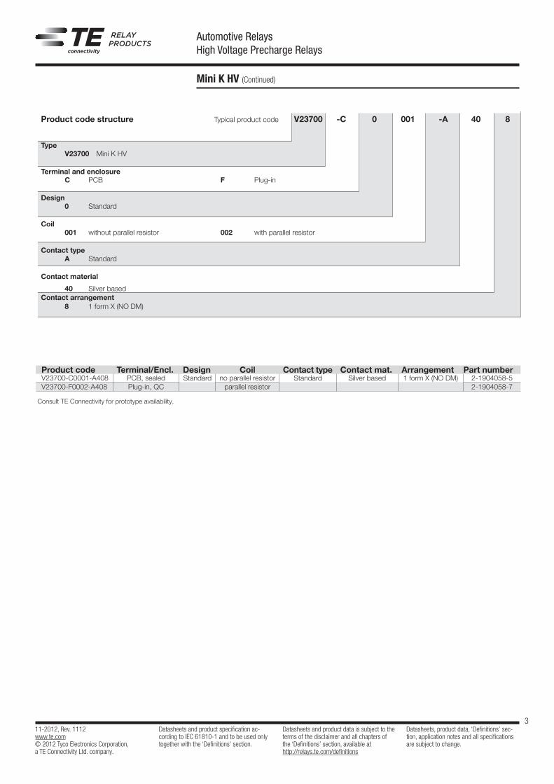
Product code structure Typical product code V23700 -C 0 001 -A 40 8 Type V23700 Mini K HV
Terminal and enclosure C PCB F Plug-in
Design 0 Standard
Coil 001 without parallel resistor 002 with parallel resistor
Contact type A Standard
Contact material
40 Silver basedContact arrangement 8 1 form X (NO DM)
Product code Terminal/Encl. Design Coil Contact type Contact mat. Arrangement Part numberV23700-C0001-A408 PCB, sealed Standard no parallel resistor Standard Silver based 1 form X (NO DM) 2-1904058-5V23700-F0002-A408 Plug-in, QC parallel resistor 2-1904058-7
Consult TE Connectivity for prototype availability.
Notes regarding PCB-layout and terminal assignment: Pin 4 must not be electrically connected, no solder eye at that pin is allowed, only a drill-hole without via Potential assignment of pins: - pins 1; 2: low voltage (LV)
- pins 5; 7; 4(*): high voltage (HV) - pin 8a; 8b: no potential but internally connected (*) pin 4 is on HV potential in ON-state of relay only.
Notes regarding clearance and creepage distances: The required clearance and creepage distances between HV and LV potential must be ensured. Layout of the PCB has to ensure min. clearance and creepage distances of conducting relay parts and relay terminal 1 and conducting relay parts and terminal 2 respectively. Refer to detail drawing.
Minimum distance to neighboring ferruginous parts: 3mm.