Embed Size (px)
Citation preview
Institut fürTechnische Informatik undKommunikationsnetze
Autonomic Identifier Allocation for ANA(AIA)
Mathias Fischer
Semester ThesisWinter Semester 2008
January 7, 2009
SA-2008-23
Supervisor: Prof. Dr. B. PlattnerAdvisors: Ariane Keller, Theus Hossmann, Dr. Martin May
Computer Engineering and Networks Laboratory, ETH Zurich

2

3
Abstract
In new networking architectures autonomy is very important – novelnetworks should be able to organise and configure themselves autonomously.One of the most important parts of configuring applications and proto-cols is identifier allocation, because for most applications having a uniqueidentifier is crucial, in order to be able to communicate with each other.In this semester thesis we designed and implemented an autonomous anddistributed system that is able to provide unique identifiers to all kindsof applications and protocols in the Autonomic Networking Architecture(ANA) framework. It generates random identifiers based on a regularexpression provided by the requesting application, and checks them foruniqueness in a specified scope. The use of ‘Autonomic Identifier Allo-cation’ simplifies configuration and therefore the set up of networks andbrings an important portion of autonomy to the ANA project.

4
CONTENTS 5
Contents
1 Introduction 7
2 Related Work 82.1 Zeroconf . . . . . . . . . . . . . . . . . . . . . . . . . . . . . . . . 82.2 Bonjour . . . . . . . . . . . . . . . . . . . . . . . . . . . . . . . . 82.3 Unique Identifier Allocation Protocol . . . . . . . . . . . . . . . . 92.4 Zeroconf Mobile Muti-Hop Ad-Hoc Networks . . . . . . . . . . . 9
3 ANA 103.1 Goal . . . . . . . . . . . . . . . . . . . . . . . . . . . . . . . . . . 103.2 Architecture . . . . . . . . . . . . . . . . . . . . . . . . . . . . . . 103.3 The Compartment API . . . . . . . . . . . . . . . . . . . . . . . 113.4 Terminology . . . . . . . . . . . . . . . . . . . . . . . . . . . . . . 12
4 Design and Implementation 134.1 Initiation . . . . . . . . . . . . . . . . . . . . . . . . . . . . . . . 134.2 Identifier Generation . . . . . . . . . . . . . . . . . . . . . . . . . 134.3 Allocation Process . . . . . . . . . . . . . . . . . . . . . . . . . . 144.4 Disjoint Compartments . . . . . . . . . . . . . . . . . . . . . . . 154.5 Duplicate Identifiers . . . . . . . . . . . . . . . . . . . . . . . . . 174.6 Implementation of Function Flow . . . . . . . . . . . . . . . . . . 184.7 XRP Messages . . . . . . . . . . . . . . . . . . . . . . . . . . . . 204.8 API . . . . . . . . . . . . . . . . . . . . . . . . . . . . . . . . . . 21
5 Validation and Evaluation 225.1 Developement and Test Environment . . . . . . . . . . . . . . . . 225.2 Validation . . . . . . . . . . . . . . . . . . . . . . . . . . . . . . . 225.3 Evaluation . . . . . . . . . . . . . . . . . . . . . . . . . . . . . . . 26
6 Future Work 286.1 Improved Identifier Generation . . . . . . . . . . . . . . . . . . . 286.2 Duplicate Identifiers . . . . . . . . . . . . . . . . . . . . . . . . . 286.3 Publishing AIA . . . . . . . . . . . . . . . . . . . . . . . . . . . . 29
7 Summary 30
A How To 33A.1 Starting and Using AIA . . . . . . . . . . . . . . . . . . . . . . . 33A.2 API Usage . . . . . . . . . . . . . . . . . . . . . . . . . . . . . . . 34
B Definition of Task 37
C Project Plan 41

6 CONTENTS
7
1 Introduction
The ANA (Autonomic Network Architecture) [1] project1 aims at exploringnovel ways of organising and using networks beyond legacy Internet technology.ANA is designed to provide a networking system that is more flexible than thefixed network stack of today’s Internet. The ANA project states that a newarchitecture should be designed in a way that its functionality is scalable –an architecture should allow both different functionality and different ways ofimplementing a given functionality.One of ANA’s key properties is autonomy. According to the project, novelnetworks should be able to organise themselves. This minimises the effort ofadministrators to set up complicated networks. A very important part of con-figuring a network and its applications and protocols is identifier allocation. Formost applications it is crucial to have unique identifiers, in order to be able tocommunicate with each other. IP needs unique IP addresses, Ethernet needsunique MAC addresses, even a chat application needs unique user names inorder to work properly.Even though ANA aims to be autonomous and despite the importance of uniqueidentifiers, ANA lacks of a system that is able to automatically allocate iden-tifiers. Identifiers, for example IP addresses, need to be configured manually.This task can become very complicated as a network grows and hosts join andleave the network.In this semester thesis we designed and implemented an autonomous and dis-tributed system that is able to provide its identifier allocation functionality toall kinds of applications and protocols. It generates different types of identi-fiers and checks them for uniqueness in a specified scope. This system is calledAutonomic Identifier Allocation or short AIA.The remainder of this thesis is organized as follows: In Section 2 we will writeabout the most important related projects. Section 3 will explain importantANA abstractions and structures that are important to understand AIA. Thedesign and implementation of Autonomic Identifier Allocation will be describedin Section 4. In Section 5 we will show some validation and evaluation tests. InSection 6 finally, we will describe where this work can be further improved andwhat points would be interesting to have a deeper look into.
1See Section 3 for a detailed description of the ANA project.
8 2 RELATED WORK
2 Related Work
In this section, the most important projects dealing with autonomic name andaddress allocations will be described. First, we will describe Zeroconf [2], proba-bly the most famous project in this area of which Bonjour [3] is a specific imple-mentation. The Unique Identifier Allocation Protocol [4] is a system that checksdifferent types of identifiers, provided by an application, for their uniqueness.Finally, IP Address Configuration Algorithm for Zeroconf Mobile Muti-hop Ad-Hoc Networks [5], describes a distributed algorithm for Ad-Hoc networks thatis based on agents that maintain a list of all assigned IP addresses.
2.1 Zeroconf
Zeroconf [2] is a working group which aims at developing a technique to connectcomputers and devices in a local network without the need of manual configu-ration. It consists of three main parts:
• automatic allocation of IP addresses without DHCP
• automatically resolve and distribute host names
• automatic service discovery
The first part of Zeroconf is described in the Dynamic Configuration of IPv4Link-Local Addresses [6] which is based on ARP (Address Resolution Protocol)[7]. According to this document, a host basically chooses an address out ofthe 169.254/16 network (without the reserved 256 first and 256 last addresses)and claims that this is its new address. This is done by sending ARP probes– broadcast ARP messages with source address set to 0.0.0.0 and destinationset to the newly chosen IP address. If another host already uses this address itresponds with an ARP reply message what causes the claiming host to give upand choose another address. Once an address claim was successful, that meansfor a given time no ARP messages for the same IP have been received, ARPannouncements are broadcasted over the network to make sure all hosts knowthe newly chosen address. ARP announcement messages are similar to ARPprobes but with source and destination address set to the new IP address.If a host receives an ARP message whose source IP address is equal to its ownaddress there must be a conflict. Conflicts can occur during the process offinding an IP address because Zeroconf first choses a random IP and only thenchecks whether this address is still available. On the other hand, conflicts canalso occur after all host already had assigned an address, due to the connectionof previously disjoint networks.After a successful claim, a host doesn’t give up its new address straight away if aconflict occurs – it tries to defend the address by sending an ARP announcementmessage. To avoid deadlocks where two or more hosts try to defend the sameIP address, a host gives up its IP address if it sees multiple conflicts during acertain time period.
2.2 Bonjour
Bonjour [3] (formerly known as Rendezvous) is a Zeroconf implementation byApple. The address allocation part basically works similar to [6]. Bonjour is
2.3 Unique Identifier Allocation Protocol 9
only needed if the host fails to receive an address from a DHCP server. OnApple OS-X, if Bonjour address allocation is used, not one but ten addressesare claimed in series and the first of them working is taken. Even if Bonjour setsa link-local address, DHCP is tried every five minutes. Since modern operatingsystems are able to detect whether an Ethernet interface is connected, Bonjouraddress allocation can be triggered by plugging a cable.
2.3 Unique Identifier Allocation Protocol
The Unique Identifier Allocation Protocol [4] is a by now expired internet draft.It proposes a protocol which offers a service to applications which assures thata requested name is only allocated if it’s not already in use by another instanceof the application in the network. It supports multiple types of identifiers (e.g.network addresses or host names). The identifier, however, is chosen by the ap-plication itself. The Unique Identifier Allocation Protocol checks the availabilityof the identifier and returns whether it’s still available. An availability check isdone by claiming an identifier and waiting for hosts denying this claim. If noneof the hosts deny the claim during a specified period of time, the identifier isstill available.
2.4 Zeroconf Mobile Muti-Hop Ad-Hoc Networks
In [5], the authors propose an agent-based addressing algorithm for ad-hoc net-works. Each node can either be bound (having an address) unbound (having noaddress) or an agent. A node in the unbound state waits for an agent to send aVerify-Packet with the network’s full address list. A Verify-Packet is basically aperiodic request from the agent to all nodes to verify their address. If no addresslist is received for a certain period of time, the node decides to switch to theagent state. Otherwise the node sends an Address-Request to the agent. Nodesthat are already bound to an address have to confirm their address after eachreceived Verify-Packet. The agent therefore gets aware of all used addresses andis able to provide addresses to requesting nodes.
10 3 ANA
3 ANA
Before describing the Autonomic Identifier Allocation system in Section 4, wewill provide some explanations of ANA, its functionality and important abstrac-tions used.
3.1 Goal
The ANA (Autonomic Network Architecture) [1] project aims at exploring andimplementing new ways of networking. Its ultimate goal is the flexible andautonomous formation of network nodes as well as whole networks. In today’sinternet architecture, IP is the most important protocol – at the same time itis the main technologic bottleneck – there are many protocols that run on IPand many technologies IP can run on, but all devices that are connected to theinternet need to communicate through the Internet Protocol. The ANA projectclaims that a new architecture should be designed in a way that its functionalityis scalable – both horizontally (different functionality) and vertically (differentways of integrating abundant functionality).ANA is a project participated by numerous universities and research institutes.Its objective is to provide an architectural framework which allows the imple-mentation of the full range of network technologies, such as small local areanetworks, mobile ad-hoc networks or even global scale networks like the Inter-net. An important part of ANA is autonomy – it is the intention of the project tofacilitate the self-* features of autonomic networking such as self-management,self-organisation and self-configuration.
3.2 Architecture
ANA mainly consists of two parts, the MINMEX – a core which has to be pro-vided by every ANA node, and the playground where the actual network func-tionality is implemented. The playground consists of multiple so called brickswhich provide some functionality to the network, e.g. encryption, compressionor connection management. Multiple bricks can be conceptually grouped tofunctional blocks – which provide a service to the network. For example thefunctional block IP consists of multiple bricks for forwarding, routing or check-sum calculation. All bricks communicate via the MIMNEX core using the ANAcompartment API.Functional blocks which are part of the same node or share the same networkprotocol are in the same compartment. A network compartment can be seen asan abstraction similar to a subnet or a virtual network. A node compartment isbasically the set of all functional blocks (and their interconnection) of a singlenode.The compartment abstraction allows the decomposition of communication net-works into smaller and manageable units. In addition a compartment hides itsinternal implementation, it only provides some specified functionality to func-tional blocks.In order to allow for dynamic rebinding of the information flow between func-tional blocks, Information Dispatch Points (IDPs) have been introduced. Com-munication between functional blocks happens always via IDPs. The Infor-mation Dispatch Table (IDT) stores the association between bricks and IDPs.
3.3 The Compartment API 11
Ethernet Compartment
node A
z
y
“ip” z“wired+eth01” y
KVR:
ETH
IP
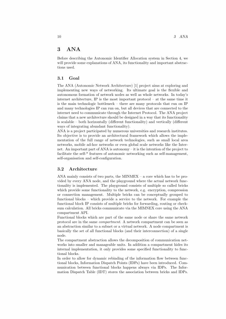
Figure 1: ANA abstractions at the example of a node with ETH and IP func-tional blocks, Ethernet segment and the KVR.
Compartments are identified by keywords which describe their service. The KeyValue Repository (KVR) stores the association between these keywords and thecorresponding IDPs.The abstraction of a communication service provided by a compartment is calledinformation channel. Information channels only exist inside the bounds of acompartment. Figure 1 shows a node with an Ethernet compartment, twofunctional blocks and the KVR storing the associations of IDPs and keywords.
3.3 The Compartment API
Compartments require some kind of registration function allowing bricks to be-come a member of the compartment. A similar function is needed to leave thecompartment. Compartments that use identifiers to name or address their mem-bers need to manage the identifier space themselves. A compartment which usesidentifiers also needs to provide a function which is able to resolve an identifierand obtain and return the information how to to communicate with this entity.Further compartments typically include routing functionality in order to finda communication path between any information source and destination withinthe compartment.In ANA a context describes the region in which a service is available, this canbe restricted to a certain subnet, to the local node (context ".") or to themaximum reachable context (context "*").The following primitives implement the registration and the resolution function-ality, respectively:
publish The primitive IDPp = publish(IDPc,context,service,timeout) re-quests from a compartment (identified by IDPc) that a certain service(service) becomes reachable via the compartment in a certain context(context), it returns an IDP (IDPp) by which the service can be accessed.The timeout parameter specifies the maximum time allowed for this ac-tion.

12 3 ANA
resolve The primitive IDPi = resolve(IDPc,context,service,timeout) isasking a compartment (again identified by IDPc) for an information chan-nel to a certain service (service) in a given context (context), it returnsthe IDP (IDPi) of the information channel requested. The timeout pa-rameter specifies the maximum time allowed for this action, after thattime resolve returns without having found the service.
3.4 Terminology
According to the ANA Blueprint [8] names, addresses and identifiers can bedistinguished as follows:
Identifier An identifier is a finite sequence of symbols of a given alphabet, thatis used to identify a certain entity of a set, an identifier therefore can beeither a name or an address.
Name A name is a globally unique identifier used for recognition of a givenentity. Usually names aim at being easily recognisable by humans, forexample a chat user name.
Address An address is an identifier that is not only used for identification butalso for routing and forwarding purposes. An IP address for example doesnot only identify a host but also contains information how a route can befound to it.
The abstractions and terms introduced in this section are very important forthe further understanding of the functionality of AIA, which is described in thefollowing section.
13
4 Design and Implementation
This section shows the design and implementation of AIA. One of the basic ques-tions about the design of AIA is how the allocation of an identifier is triggered,what will be described in the first subsection. Once AIA has been triggered,an identifier has to be generated - how this is done is shown in the next sub-section. The centrepiece of this thesis - the allocation process - is explained inSubsection 4.3. We will also show how AIA is extended such that addresses caneven be allocated in disjoint compartments. Further, we will have a look at theproblem that the same identifier could be allocated to multiple instances of anapplication. After pointing out the most important functions and threads inAIA and how the program control flows between them, we will explain intro-duced messages and what they are used for. In the end of this section the APIwill be described.
4.1 Initiation
Since ANA aims to be scalable in functionality, it doesn’t make sense to imple-ment a protocol that only assigns IP addresses within Ethernet Compartments.It should be possible to assign arbitrary identifiers in an arbitrary compartment.This generic property is definitely one of the most important points about thedesign of an identifier allocation mechanism for ANA.The mentioned projects in Section 2 follow different paradigms how an address(or more general: identifier) allocation process is initiated. Bonjour [3] forexample is initiated when a cable is plugged and no IP address could be foundusing a DHCP server. UIAP [4] on the other hand leaves the initialization to theclient application. In this case, the next question is whether the name allocationprocess also needs to generate an appropriate identifier or whether this is leftto the application.Since a generic allocation process doesn’t know anything about the structureof the address space of the compartments, the identifier should be chosen bythe application or protocol that needs an identifier. On the other hand, we donot want too much functionality of the allocation and generation process beingplaced in the applications themselves.In order to achieve a generic identifier allocation process, that still doesn’t needthe applications to generate an identifier we decided to let the application de-scribe its identifier space with a regular expression. Further the application hasto define the compartment in which an identifier needs to be unique. And finallyit can specify a timeout which is the maximum time AIA should try to find anavailable identifier before giving up.
4.2 Identifier Generation
As mentioned above, the generation of identifiers is based on regular expressions[9] given by the application. Regular expressions are already used by the cfinder[10] brick to identify identifiers belonging to a certain brick. Regular expres-sions can describe any kind of address or name space – even an address space’sstructure, like subnetting in the example of IP addresses, can be implemented –since some parts of the IP address can be kept fixed whereas other parts can bedescribed as being variable. It is even possible to provide a list of allowed names
14 4 DESIGN AND IMPLEMENTATION
in the form of a regular expression. Some examples for name spaces describedby regular expressions:
IPv4 (([0-9]|[1-9][0-9]|1[0-9]{2}|2[0-4][0-9]|25[0-5])\\.){3}([0-9]|[1-9][0-9]|1[0-9]{2}|2[0-4][0-9]|25[0-5])
Zeroconf address range 169\\.254\\.([1-9]|([1-9][0-9])|(1[0-9][0-9])|(2[0-4][0-9])|25[0-4])\\.([0-9]|([1-9][0-9])|(1[0-9][0-9])|(2[0-4][0-9])|25[0-5])
MAC address (([0-9]|[A-F]):){5}([0-9]|[A-F])
List (alpha|beta|gamma|delta)
The actual generation of an identifier is done by calling a Perl script. Perl is verymighty in terms of regular expressions and there is a module that does exactlywhat’s needed for the generation of identifiers based on regular expressions:It provides a function that generates a string that matches a given regularexpression. In order to be able to call this function, the following two Perlmodules need to be installed:
• Parse::RandGen::Regexp
• YAPE::Regex
The Perl script is called with the popen command which opens a UNIX pipe toa command line program. It is called as follows:
regen.pl regex
where regex is a Perl regular expression, or in other words a string representinga regular expression enclosed by backslashes. For example:
regen.pl /10\.0\.0\.[0-9]/
4.3 Allocation Process
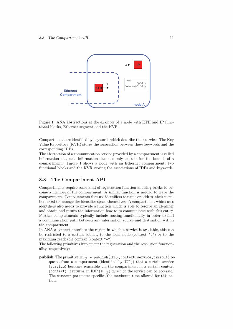
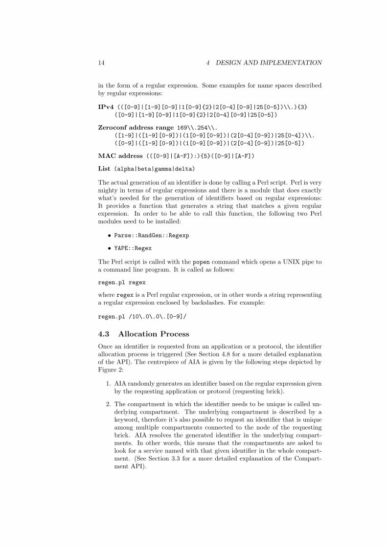
Once an identifier is requested from an application or a protocol, the identifierallocation process is triggered (See Section 4.8 for a more detailed explanationof the API). The centrepiece of AIA is given by the following steps depicted byFigure 2:
1. AIA randomly generates an identifier based on the regular expression givenby the requesting application or protocol (requesting brick).
2. The compartment in which the identifier needs to be unique is called un-derlying compartment. The underlying compartment is described by akeyword, therefore it’s also possible to request an identifier that is uniqueamong multiple compartments connected to the node of the requestingbrick. AIA resolves the generated identifier in the underlying compart-ments. In other words, this means that the compartments are asked tolook for a service named with that given identifier in the whole compart-ment. (See Section 3.3 for a more detailed explanation of the Compart-ment API).
4.4 Disjoint Compartments 15
(2) resolve(10.0.0.3)
(4) 10.0.0.3
(3) [timeout]
AIA IP
Ethernet
(5) publish(10.0.0.3)
(1) getIdentifier(10.0.0.\d)
Figure 2: Diagram of the allocation process at the example of IP on an Ethernetsegment. First IP requests an identifier based on a regular expression (1). AfterAIA generates a matching identifier, it tries to resolve it in the Ethernet com-partment (2). If the resolve request times out (3), AIA can return the identifierto IP (4), which can publish it in the Ethernet compartment (5).
• If the resolve request is successful, the identifier was found in thecompartment. That means that there is already a service using thatidentifier and it therefore cannot be returned to the application.→ Go to step 1.
• If the resolve request times out (the timeout for resolve is specifiedby AIA), the compartment is not able to find a service with the givenname. Therefore the generated identifier can safely be returned tothe requesting application.
Once an unused identifier could be found and returned to the requesting brick,the application can publish a service named by that identifier in one of theunderlying compartments.If AIA was not able to find an available identifier after a certain number of triesor within the time specified by the requesting brick, it returns NULL instead ofthe identifier. A maximum number of tries is specified to prevent AIA fromtesting the same identifier over and over again.
4.4 Disjoint Compartments
Zeroconf [2] for example only assigns IP addresses in the same Ethernet segment.However, it is undoubtedly useful to be able to have an IP address that isunique among multiple underlying segments. This does particularly make senseif multiple underlying networks implement different technologies between which
16 4 DESIGN AND IMPLEMENTATION
AIA
Ethernet Ethernet Ethernet
IP
Ethernet
AIA
resolve
forward
resolve
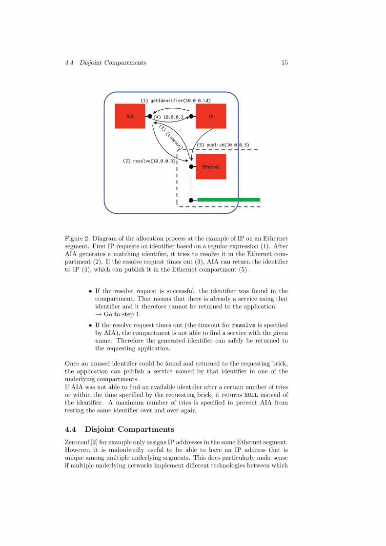
Figure 3: Diagram of forwarding procedure. AIA sends a forward request to allreachable AIA bricks.
AIA
EthernetEthernet
publishpublish
Figure 4: Diagram of AIA publishing itself into multiple underlying compart-ments. Afterwards this AIA brick is reachable in both compartments.
broadcast messages, and therefore also resolve requests, are not forwarded. It’salso useful to assign unique IP addresses among multiple Ethernet segmentsthat are connected to the same node but not yet bridged. If later switchingfunctionality is introduced, the IP addresses are already unique among bothsegments.With the above mentioned procedure it’s only possible to verify the uniquenessof an identifier in compartments that are available on the local node. In orderto be able to verify the uniqueness among compartments that are not directlyconnected to the local node, the basic procedure of AIA needs to be extended,see Figure 3 for a scheme showing the forwarding procedure.If an AIA brick publishes itself in all underlying compartments (see Figure 4),itis from then on reachable by all nodes connected by the underlying compart-ments. In addition to only check local underlying compartments for an identi-fier’s uniqueness, an identifier is forwarded to all reachable AIA bricks where itis checked in all available underlying compartments as well. These AIA bricksforward the request to all reachable AIA bricks again – therefore basically aflooding of AIA forward messages is implemented. In order to distinguish theforward messages belonging to a certain request, they carry a sequence number.And in order to stop the forwarding procedure after a certain time, the messagesalso carry a hop count. With each hop the timeout value is decreased.
4.5 Duplicate Identifiers 17
networkcompartmentapplication 1 application 2
IP
Ethernet
IP
Ethernet
resolve
publish
[timeout]resolve
publish
[timeout]
Figure 5: Scheme showing how duplicate identifiers are allowed.
Since the set of underlying compartments is only known after an application re-quested an identifier, AIA cannot be previously published. This leads to the factthat a node or an AIA brick, respectively can only accept a forwarded request ifit was previously used to find an identifier in the same compartment. In otherwords, in order to achieve unique identifiers throughout all compartments, theinterconnecting nodes where compartments are joining, need to request iden-tifiers before other nodes. See Section 6.3 for another possible approach ofpublishing AIA into compartments.
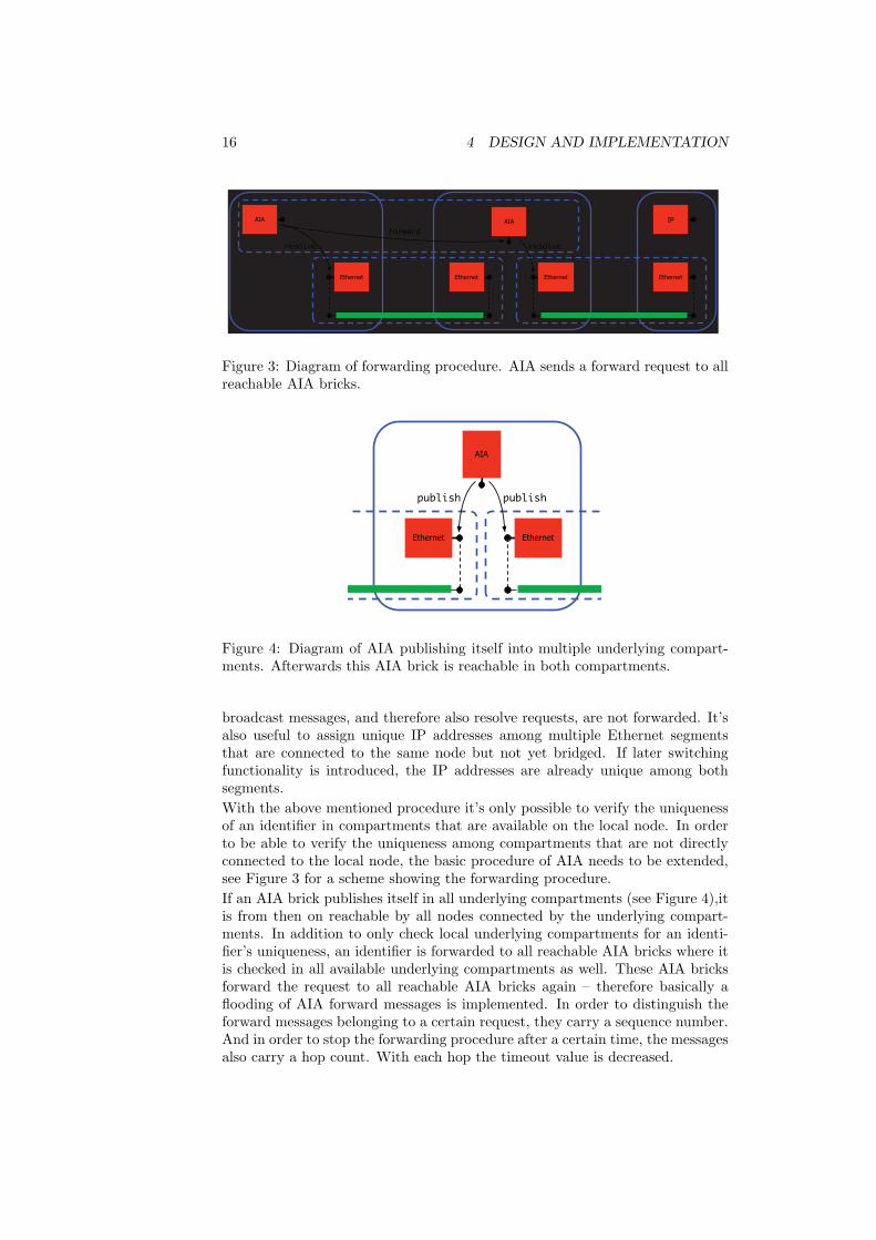
4.5 Duplicate Identifiers
Since the identifier is in a first phase generated and tested by AIA and thenin a second phase published by the application, it is possible that the sameidentifier gets allocated multiple times. Figure 5 shows how it can happen, thatduplicate identifiers are allowed. It shows two different nodes connected by thesame underlying compartment. If the two instances of AIA on these two nodeshappen to generate the same identifier at the same time, both of them try toresolve this identifier in the underlying compartment. If before, no such identifierexisted both resolve request will lead to a timeout and both instances of AIAwill allow their requesting applications to publish this identifier, what will leadto a name conflict. Knowing that this problem might occur, we will analysewhat factors are important and how the probability of duplicate identifiers canbe decreased.The problem of duplicate identifiers can only occur if two (or more) requestsfor the same identifier in the same compartment are made at the same time.Therefore three factors are important:
Identifier Space Utilisation Since identifiers are generated randomly, theprobability that the same unused identifier is generated twice dependson the usage of the identifier space. If enough identifiers are still avail-able, the probability that the same identifier is generated multiple timesis rather small.
Timeout Since the timeout value defines the duration of a resolve request, a
18 4 DESIGN AND IMPLEMENTATION
lower timeout decreases the probability of two timeouts happening at thesame time. However, a timeout value that is too low, can lead to theproblem that a resolve request doesn’t find a service even though it wouldexist.
Request Rate Two resolve requests only happen at the same time, if twoidentifier requests were made at the same time for the same compartment.Hence, the probability of the problem happening depends on the rate atwhich identifier requests are made for a given compartment.
For further possibilities to decrease the probability of duplicate identifiers, pleaserefer to Subsection 6.2 in the Future Work Section, since this problem is nothandled in the current implementation of AIA.
4.6 Implementation of Function Flow
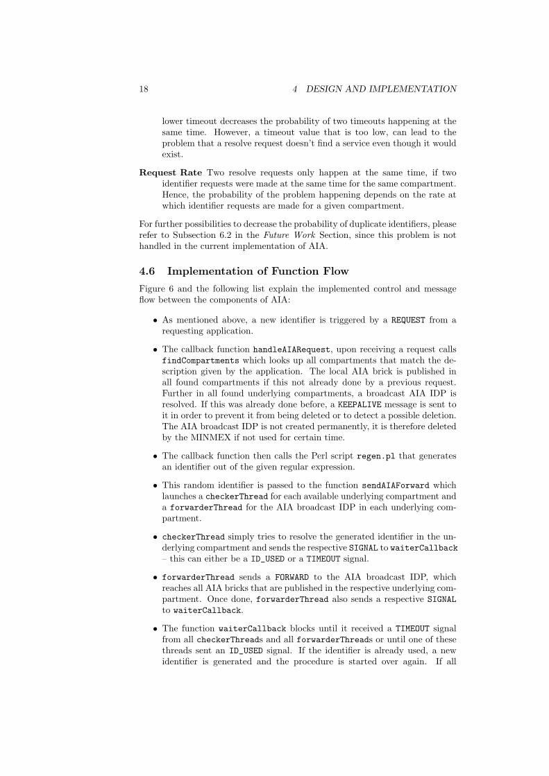
Figure 6 and the following list explain the implemented control and messageflow between the components of AIA:
• As mentioned above, a new identifier is triggered by a REQUEST from arequesting application.
• The callback function handleAIARequest, upon receiving a request callsfindCompartments which looks up all compartments that match the de-scription given by the application. The local AIA brick is published inall found compartments if this not already done by a previous request.Further in all found underlying compartments, a broadcast AIA IDP isresolved. If this was already done before, a KEEPALIVE message is sent toit in order to prevent it from being deleted or to detect a possible deletion.The AIA broadcast IDP is not created permanently, it is therefore deletedby the MINMEX if not used for certain time.
• The callback function then calls the Perl script regen.pl that generatesan identifier out of the given regular expression.
• This random identifier is passed to the function sendAIAForward whichlaunches a checkerThread for each available underlying compartment anda forwarderThread for the AIA broadcast IDP in each underlying com-partment.
• checkerThread simply tries to resolve the generated identifier in the un-derlying compartment and sends the respective SIGNAL to waiterCallback– this can either be a ID_USED or a TIMEOUT signal.
• forwarderThread sends a FORWARD to the AIA broadcast IDP, whichreaches all AIA bricks that are published in the respective underlying com-partment. Once done, forwarderThread also sends a respective SIGNALto waiterCallback.
• The function waiterCallback blocks until it received a TIMEOUT signalfrom all checkerThreads and all forwarderThreads or until one of thesethreads sent an ID_USED signal. If the identifier is already used, a newidentifier is generated and the procedure is started over again. If all
4.6 Implementation of Function Flow 19
anaThread
resolve
anaThread
analock
receive
popenfunction call
function call
function callfunction call
SIGNAL
KEEPALIVEBACKW
ARD
FORW
ARD
/KEEPALIVE
BACKWA
RD
FORW
ARD
/KEEPALIVE
FORWARD
SIGNAL
REQUEST
REPLY
handleAIA
Request
Underlying Com
partment
AIA
Broadcast
regen.pl
getIdenti�er
handleAIA
Forward
sendAIA
Forward
�ndCompartm
ents
waiterCallback
checkerThreadforw
arderThreadansw
er_receiver
UnderlyingCompartment
AIA RequestingBrick
Figure 6: The control and message flow between components of AIA.

20 4 DESIGN AND IMPLEMENTATION
threads send a TIMEOUT signal, handleAIARequest sends a REPLY mes-sage with the found identifier back to the requesting brick.
• requestReply can be used to send a message to an IDP and in the sametime request an answer from it, i.e. the function blocks until a reply isreceived (or the timeout is reached). But since requestReply doesn’t workas expected to send FORWARD messages to a broadcast IDP and receive ananswer, the service answer_receiver is used by the forwarderThread toreceive answers from other nodes, it is published (and therefore available)in all underlying compartments.
• If a node receives a FORWARD message, handleAIAForward calls the func-tion findCompartments in order to update the list of underlying compart-ments, and then calls sendAIAForward in order to check the availabilityof the identifier and forward the the request. If waiterCallback receivesthe signal that the identifier is used, it sends a BACKWARD message back tothe node that sent the FORWARD request (via answer_receiver), otherwiseit simply doesn’t do anything in order to let the request time out.
4.7 XRP Messages
XRP (eXtensible Resolution Protocol) [11] is the standard format for messagesbetween ANA bricks. An XRP message consists of a command (i.e. a messagetype) and multiple arguments (i.e. values). The following list shows the XRPcommands we defined to support the functionality of AIA. Note that the lastpart of the XRP command name can also be found in Figure 6.
XRP CMD AIA REQUEST is the request that is made out of the request-ing application. The function getIdentifier which generates a REQUESTis provided by aia.h to simplify utilisation. A REQUEST contains the de-scription of the underlying compartments and the regular expression.
XRP CMD AIA REPLY is a reply to a request from an application. Areply can either carry the identifier string or the message that no identifiercould be found.
XRP CMD AIA FORWARD is a forwarding message between two AIAnodes. It consists of a sequence number (in order to distinguish requests),a hop count, the identifier that needs to be checked and the description ofthe underlying compartments.
XRP CMD AIA BACKWARD is the reply to a forwarding message. Areply to a forward is only sent if the identifier could be found, otherwisethe forward request will be let timing out. Therefore a BACKWARD messagesalways consist of the ID_USED flag.
XRP CMD AIA SIGNAL is used to inform the callbackWaiter functionthat a checkerThread or forwarderThread has finished. It’s either aTIMEOUT or an ID_USED signal.
XRP CMD AIA KEEPALIVE is sent to the AIA broadcast IDP in ordernot to let it disappear because it wasn’t used for too long or to detectthat it was already deleted. Non-permanently published IDPs are deleted

4.8 API 21
by the MINMEX if not used for a certain time. A received KEEPALIVEmessage is simply ignored.
4.8 API
AIA provides an API to all other bricks in order to request an identifier. Afterhaving imported aia/aia.h the API basically only consists of a single functioncall:
char* getIdentifier(char* regex,struct service_s* description,struct timespec* timeout);
This function returns a string with the found unique identifier or NULL if nonecould be fount. It takes the following arguments:
• char* regex A string with the regular expression that matches all (andonly) valid identifiers.
• struct service_s* description A service_s struct that describes thecompartments in which the identifier has to be unique.
• struct timespec* timeout Maximum time AIA can try to find an iden-tifier before giving up, without having found one. Note that this timeoutdoesn’t correspond with the timeout parameter of a resolve request whichis set by AIA.
In the Section A.2 in the appendix we will shortly describe how we adopted theIP configuration and the chat application bricks to use AIA.
22 5 VALIDATION AND EVALUATION
ssh
ssh
internet access
eclipse
make, gcc
virtualBox
ANA
minerva
eth1
ssh
ANA
apollo jupiter
eth1
ssh
ANA
pc-10083
eth1
eth0
eth0
eth0
ana-net
ana-shared ana-shared ana-shared ana-shared
• • •
• • •
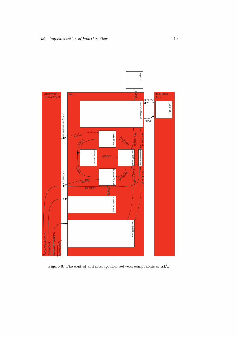
Figure 7: Diagram of the Test Environment
5 Validation and Evaluation
5.1 Developement and Test Environment
To be able to test AIA on a network environment without the need of settingup a network with multiple machines, we decided to use multiple virtual ma-chines running on a single host machine using VirtualBox2. For fast and simplecompilation and distribution of the new ANA binaries, a folder from the hostoperating system is shared among all the guest systems. Since all the operat-ing systems are exactly the same (Ubuntu 8.04), we are able to compile thesource on the host system and distribute the binaries afterwards. For simplershell script execution we further installed an ssh server on all guest systems andredirected a certain port to each one of them. See Figure 7 for a detailed viewof the test environment.
5.2 Validation
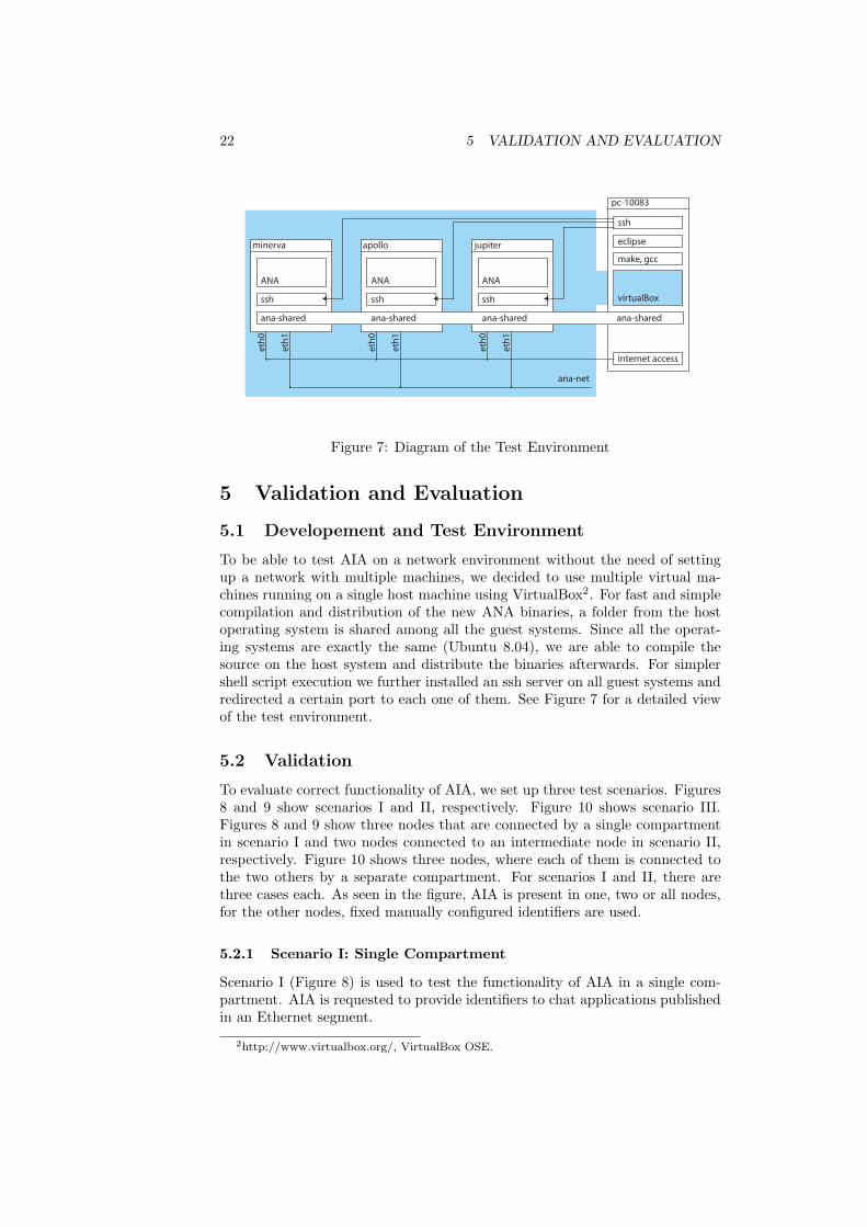
To evaluate correct functionality of AIA, we set up three test scenarios. Figures8 and 9 show scenarios I and II, respectively. Figure 10 shows scenario III.Figures 8 and 9 show three nodes that are connected by a single compartmentin scenario I and two nodes connected to an intermediate node in scenario II,respectively. Figure 10 shows three nodes, where each of them is connected tothe two others by a separate compartment. For scenarios I and II, there arethree cases each. As seen in the figure, AIA is present in one, two or all nodes,for the other nodes, fixed manually configured identifiers are used.
5.2.1 Scenario I: Single Compartment
Scenario I (Figure 8) is used to test the functionality of AIA in a single com-partment. AIA is requested to provide identifiers to chat applications publishedin an Ethernet segment.
2http://www.virtualbox.org/, VirtualBox OSE.
5.2 Validation 23
Ethernet Ethernet
AIA
Ethernet
Ethernet Ethernet
AIA AIA
Ethernet
Ethernet Ethernet
AIA AIA AIA
Ethernet
(I.a)
(I.b)
(I.c)
node A node B node C
node A node B node C
node A node B node C
Figure 8: Diagram of testing scenario I, three nodes connected by a singleEthernet compartment. AIA is only used in the nodes with an AIA brick.
First, two of three nodes are configured manually, that means chat namesalpha and beta are given to the chat applications. On the third node, AIAis asked to find an available identifier specified by the simple regular expression(alpha|beta|gamma), assuming correct functionality, only identifier gamma isvalid. The test is done multiple times and AIA always returns gamma, whatshows correct functionality for the first case of scenario I.
24 5 VALIDATION AND EVALUATION
Ethernet Ethernet
AIA
AIA
Ethernet Ethernet
AIA
Ethernet Ethernet Ethernet Ethernet
AIA
AIA
Ethernet Ethernet Ethernet Ethernet
AIA
(II.a)
(II.b)
(II.c)
node A node B node C
node A node B node C
node A node B node C
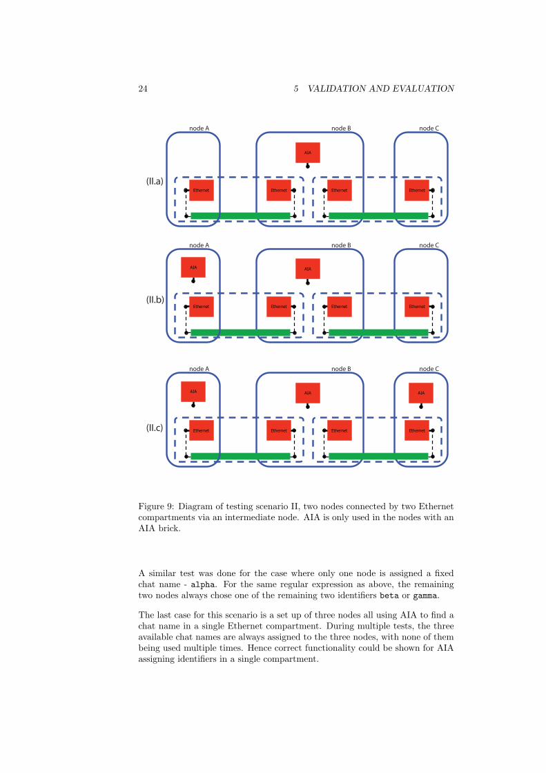
Figure 9: Diagram of testing scenario II, two nodes connected by two Ethernetcompartments via an intermediate node. AIA is only used in the nodes with anAIA brick.
A similar test was done for the case where only one node is assigned a fixedchat name - alpha. For the same regular expression as above, the remainingtwo nodes always chose one of the remaining two identifiers beta or gamma.
The last case for this scenario is a set up of three nodes all using AIA to find achat name in a single Ethernet compartment. During multiple tests, the threeavailable chat names are always assigned to the three nodes, with none of thembeing used multiple times. Hence correct functionality could be shown for AIAassigning identifiers in a single compartment.
5.2 Validation 25
Ethernet Ethernet
AIA
AIA
AIA
Ethernet
Ethernet Ethe
rnet
Ethe
rnet
node A
node B node C
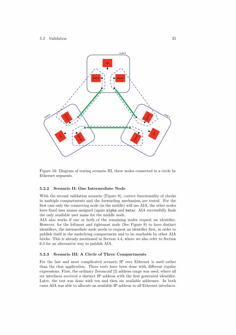
Figure 10: Diagram of testing scenario III, three nodes connected in a circle byEthernet segments.
5.2.2 Scenario II: One Intermediate Node
With the second validation scenario (Figure 9), correct functionality of checksin multiple compartments and the forwarding mechanism are tested. For thefirst case only the connecting node (in the middle) will use AIA, the other nodeshave fixed user names assigned (again alpha and beta). AIA successfully findsthe only available user name for the middle node.AIA also works if one or both of the remaining nodes request an identifier.However, for the leftmost and rightmost node (See Figure 9) to have distinctidentifiers, the intermediate node needs to request an identifier first, in order topublish itself in the underlying compartment and to be reachable by other AIAbricks. This is already mentioned in Section 4.4, where we also refer to Section6.3 for an alternative way to publish AIA.
5.2.3 Scenario III: A Circle of Three Compartments
For the last and most complicated scenario IP over Ethernet is used ratherthan the chat application. Three tests have been done with different regularexpressions. First, the ordinary Zeronconf [2] address range was used, where allsix interfaces received a distinct IP address with the first generated identifier.Later, the test was done with ten and then six available addresses. In bothcases AIA was able to allocate an available IP address to all Ethernet interfaces.
26 5 VALIDATION AND EVALUATION
0
75
150
225
300
5 10 15 20 25 30 35 40 45 50 55 60 65 70 75 80 85 90 95 100
Tim
e (S
econ
ds)
Number of Identi�ers allocated
Size of Namespace:
All identi�ers werefound afer 10 tries.
AIA returned withouthaving found anidenti�er for allrequests.
255075
100
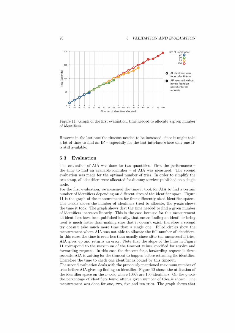
Figure 11: Graph of the first evaluation, time needed to allocate a given numberof identifiers.
However in the last case the timeout needed to be increased, since it might takea lot of time to find an IP – especially for the last interface where only one IPis still available.
5.3 Evaluation
The evaluation of AIA was done for two quantities. First the performance –the time to find an available identifier – of AIA was measured. The secondevaluation was made for the optimal number of tries. In order to simplify thetest setup, all identifiers were allocated for dummy services published on a singlenode.For the first evaluation, we measured the time it took for AIA to find a certainnumber of identifiers depending on different sizes of the identifier space. Figure11 is the graph of the measurements for four differently sized identifier spaces.The x-axis shows the number of identifiers tried to allocate, the y-axis showsthe time it took. The graph shows that the time needed to find a given numberof identifiers increases linearly. This is the case because for this measurementall identifiers have been published locally, that means finding an identifier beingused is much faster than making sure that it doesn’t exist, therefore a secondtry doesn’t take much more time than a single one. Filled circles show themeasurement where AIA was not able to allocate the full number of identifiers.In this cases the time is even less than usually since after ten unsuccessful tries,AIA gives up and returns an error. Note that the slope of the lines in Figure11 correspond to the maximum of the timeout values specified for resolve andforwarding requests. In this case the timeout for a forwarding request is threeseconds, AIA is waiting for the timeout to happen before returning the identifier.Therefore the time to check one identifier is bound by this timeout.The second evaluation deals with the previously mentioned maximum number oftries before AIA gives up finding an identifier. Figure 12 shows the utilisation ofthe identifier space on the x-axis, where 100% are 100 identifiers. On the y-axisthe percentage of identifiers found after a given number of tries is shown. Themeasurement was done for one, two, five and ten tries. The graph shows that
5.3 Evaluation 27
0
25
50
75
100
10 20 30 40 50 60 70 80 90 100
Number of tries: 1 2 5 10
Percentage of Identi�er Space used
Perc
enta
ge o
f Ide
ntife
rs fo
und
afte
r a g
iven
num
ber o
f trie
s
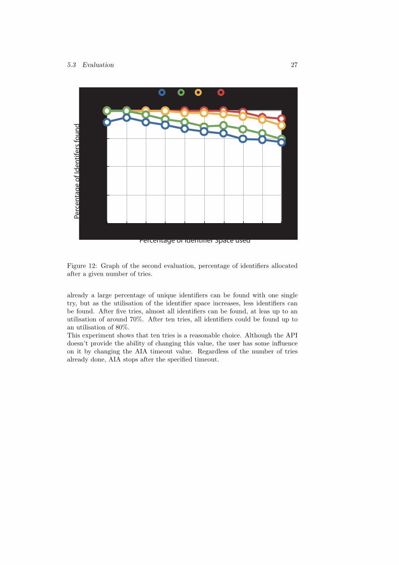
Figure 12: Graph of the second evaluation, percentage of identifiers allocatedafter a given number of tries.
already a large percentage of unique identifiers can be found with one singletry, but as the utilisation of the identifier space increases, less identifiers canbe found. After five tries, almost all identifiers can be found, at leas up to anutilisation of around 70%. After ten tries, all identifiers could be found up toan utilisation of 80%.This experiment shows that ten tries is a reasonable choice. Although the APIdoesn’t provide the ability of changing this value, the user has some influenceon it by changing the AIA timeout value. Regardless of the number of triesalready done, AIA stops after the specified timeout.
28 6 FUTURE WORK
6 Future Work
6.1 Improved Identifier Generation
The current implementation of AIA, or the Perl script in particular, randomlygenerates a string that matches the given regular expression. However, it mightbe preferable that an identifier that’s generated for a certain instance of anapplication is partially reproducible. This could be done by using the identifieror some other unique information from the underlying compartment as a seed.For example it would be desirable that the IP address that belongs to a certainEthernet interface is similar every time AIA is used to generate an IP address,in this case the Ethernet MAC address could be used as a seed. However, itshouldn’t generate exactly the same identifier each time, since AIA is based onthe idea that if an identifier is not available anymore another one is generated,and so on. This wouldn’t work if always the same identifier was generated.
6.2 Duplicate Identifiers
Even though, we argue in Section 4.5 that the probability of duplicate identifiersis quite low if certain properties are fulfilled, it would be desirable to furtherdecrease the danger of duplicate identifiers. Some possible improvements couldinclude:
Detection Mechanism Applications and protocols could be asked to providea mechanism that can detect duplicate identifiers, and in case of a conflictresend the identifier request to get a new identifier. However it should beprevented that both instances of the application re-request a new identifierand the possibility of duplicate identifiers is still around.
Verification It’s possible to provide another API function in aia.h calledverifyIdentifier, which would just check whether an identifier is re-ally unique after it was published. This functionality could be wrappedin a modified publish function:
anaLabel_t publishIdentifier(char* regex,struct service_s* service_of_underlying_compartment,struct service_s* service_to_publish,struct context_s* context_where_to_publish,struct timespec* timeout_for_aia);
This function could request an identifier, publish it and afterwards verifyits uniqueness.
Improved Identifier Generation As mentioned in Section 6.1, identifierscould be generated influenced by a seed coming from the identifier ofthe underlying compartment. Therefore the probability that the sameidentifier is generated on two different nodes is further decreased.

6.3 Publishing AIA 29
6.3 Publishing AIA
In the current implementation, AIA is only published in underlying compart-ments on a given node once AIA was requested to find an identifier in thesecompartments. This makes sense as long as nodes connecting multiple com-partments are not very often, and preferably request identifiers first.It would be possible to regularly publish AIA in all compartments available ona node. As long as AIA is only used for few types of compartments this mightbe an overhead. However, if AIA was used to find identifiers for many differentcompartments, this way of publishing AIA might be a better choice.
30 7 SUMMARY
7 Summary
In this semester thesis, we designed and implemented a generic and distributedidentifier allocation system, which is able to provide unique identifiers to anykind of application or protocol. With this Autonomic Identifier Allocation, theANA project gains on autonomy.IP networks can now be set up much easier by using the zeroconf option ofipconfig. Nodes can join existing networks without the need of manual con-figuration or a centralised server providing addresses. But AIA cannot only beused to allocate IP addresses, it provides an API that can be used by every brickwithin ANA. Identifiers can be allocated uniquely in a compartment that is builtover different underlying compartments thanks to the forwarding functionalitybuilt into AIA.However, there is the danger of duplicate identifiers. It has been showed, thatthis danger can be kept low as long as the address space is used rather sparelyand as long as identifiers request do not occur too frequently. In fact, whileevaluating and verifying AIA, I never encountered the problem of duplicateidentifiers even though also multiple requests have been started at the sametime.The contributions of this thesis to the ANA project can be summarised asfollows:
• Before starting with the work on an own identifier allocation systems, Istudied and compared different existing projects dealing with automaticdistributed identifier allocation.
• The main part of the work on this thesis consisted of the design of AIA.Many options and possibilities of an identifier allocation systems havebeen considered. Whereas the decision was made for a system as genericas possible.
• In order to be able to efficiently work on the thesis I set up an environmentof multiple virtual machines building a virtual network.
• Once planned, the project was implemented in C in the ANA framework.The result is a properly working generic application.
• The chat and the ipconfig applications were changed to use AIA’s func-tionality if needed.
• The project was verified and evaluated in different scenarios with AIAused for different applications.
I hope that in the future many bricks will use the functionality provided by AIAand that autonomic identifiers are only the first step of completely autonomouslyconfigured systems or even networks.
REFERENCES 31
References
[1] ANA Autonomic Network Architecture. http://www.ana-project.org,(7.1.2009).
[2] Zeroconf working group. http://www.zeroconf.org/, (7.1.2009).
[3] Apple Inc. Bonjour. http://developer.apple.com/networking/bonjour,(7.1.2009).
[4] A. White and A. Williams. Unique identifier allocation protocol. Internet-Draft draft-white-zeroconf-uiap-01, Internet Engineering Task Force, Oc-tober 2002. Expired on May 1, 2003.
[5] Mesut Gunes and Jorg Reibel. Ein dynamisches Adressierungsverfahren furmobile Ad-Hoc Netze. In Mobile Ad-Hoc Netzwerke, 1. deutscher Workshopuber Mobile Ad-Hoc Netzwerke WMAN, volume 11 of LNI, pages 59–78. GI,2002.
[6] S. Cheshire, B. Aboba, and E. Guttman. Dynamic configuration of IPv4link-local addresses. RFC 3927, Internet Engineering Task Force, May 2005.
[7] D. C. Plummer. An ethernet address resolution protocol. RFC 826, Net-work Working Group, November 1982.
[8] Stefan Schmid Christophe Jelger. ANA Blueprint, 2008. http://www.ana-project.org/deliverables/2007/ana-d1.456-final.pdf, (7.1.2009).
[9] Perldoc (perldoc.perl.org). perlre - perl regular expressions.http://perldoc.perl.org/perlre.html#Regular-Expressions, (7.1.2009).
[10] Christophe Jelger. The compartment finder. In Developmentofautonomic applications, pages 12–16, 2008. http://www.ana-project.org/deliverables/2007/ana-d4.3-final.pdf, (7.1.2009).
[11] Richard Gold, Per Gunningberg, and Christian Tschudin. A virtualizedlink layer with support for indirection. In FDNA ’04: Proceedings of theACM SIGCOMM workshop on Future directions in network architecture,pages 28–34, New York, NY, USA, 2004. ACM.

32 REFERENCES
33
A How To
A.1 Starting and Using AIA
All AIA code is located in the directory ./C/bricks/aia/, this also includessome scripts that start AIA with a set of standard bricks, especially the scenariosmentioned in Section 5. However, in this section we will provide a step by stepguide to start AIA for certain scenarios. All commands should be executedfrom the ANA root directory. But before AIA can be loaded, ANA has to becompiled with AIA. Thus the config.txt file needs to be changed:
• The line USER_PROCESS_BRICKS should contain at least:ip eth-vl
• The line USER_PLUGIN_BRICKS needs to contain at least:vlink ip chat cfinder aia gatesPlug eth-vl
After having added all needed bricks to the config file, ANA needs to be compiledusing make.
A.1.1 Chat Over Ethernet
The following commands start a chat application that runs over Ethernet. Inorder to be able to use the text user interface for the chat, two console windowsare needed. On the first one enter:
# start MINMEXsudo ./bin/minmex
On the second console, start vlink, Ethernet, AIA and the chat application withthe following commands:
# load vlink brick./bin/mxconfig load brick ./so/vlink.so# create new vlink./bin/vlconfig create 1# add interface eth1 to vlink./bin/vlconfig add_if vlink1 eth1# switch on vlink1./bin/vlconfig up vlink1# load Ethernet brick./bin/mxconfig load brick ./so/eth-vl.so# load AIA brick./bin/mxconfig load brick ./so/idalloc.so# load chat brick with AIA functionality./bin/mxconfig load brick ./so/agnostic_chat.so aia
eth1 has to be replaced by the name of the Ethernet interface of your machine.The chat application should be started on multiple machines and can then beused in the first console window.

34 A HOW TO
A.1.2 Zeroconf (AIA for IP Addresses in Ethernet Compartments)
AIA can be used to allocate IP adresses from the Zeroconf range in Ethernetcompartments. This is done as follows:
# start MINMEXsudo ./bin/minmex &# load vlink brick./bin/mxconfig load brick ./so/vlink.so# create new vlink./bin/vlconfig create 1# add interface eth1 to vlink./bin/vlconfig add_if vlink1 eth1# switch on vlink1./bin/vlconfig up vlink1# load cfinder brick./bin/mxconfig load brick ./so/cfinder.so# load gates plugin./bin/mxconfig load brick ./so/gatesPlug.so# start Ethernet as a standalone processsudo ./bin/eth-vl -n unix://<SOCK_FILE> &# load AIA brick./bin/mxconfig load brick ./so/idalloc.so# load IP bricks./bin/mxconfig load brick so/ip_enc.so./bin/mxconfig load brick so/ip_sum.so./bin/mxconfig load brick so/ip_fwd.so# start ipconfig as standalone process with zeroconf optionsudo ./bin/ip_cfg -n unix://<SOCK_FILE> -e eth01 -z &
Where <SOCK_FILE> stands for the newest of the files in the /tmp/ directorynamed like anaControl_gatesPlug_*.
A.2 API Usage
Section 4.8 describes the API of AIA. In this section we will describe how theAPI is used at the example of the ipconfig and the chat application.
A.2.1 Ipconfig
In order to automatically allocate IP addresses to Ethernet interfaces as in [6],we adopted the IP configuration brick to use AIA. In this case ipconfig allocatesIP addresses from the network 169.254.0.0/16 like Zeroconf. But in contrastto Zeroconf, IP addresses are unique among all ethernet compartments thatare connected to the requesting node by a node that previously assigned IPaddresses with AIA. See Section 4.4 for a more detailed description of uniqueidentifiers in disjoint compartments.
ip_cfg -e <ethernet interface> -z

A.2 API Usage 35
A.2.2 Chat
As an example that AIA cannot only be used for IP addresses, we also provide amodified version of the chat application which can be used to find unique namesthroughout a set of compartments. If the chat application is started without auser name passed as argument, AIA is automatically used to find a chat namethat is unique in the eth01 compartment.In addition when calling the chat application, it can also be specified whichprotocol needs to be used an in which compartment the user name needs to beunique.
agnostic_chat [aia [<interface> [<compartment>]]]
For example:
// find a user name in eth01agnostic_chatagnostic_chat aiaagnostic_chat aia eth01
// find a user name in eth01 but// unique in all ethernet compartmentsagnostic_chat aia eth01 wired
// find a user name in IPagnostic_chat aia ip
// find a user name in the compartment identified by the IP// 10.0.0.1 but unique in all IP compartmentsagnostic_chat aia 10.0.0.1 ip

36 A HOW TO
37
B Definition of Task
Institut fürTechnische Informatik undKommunikationsnetze
Semester Thesis
Zeroconf for ANA network compartmentsMathias Fischer
Advisor: Ariane Keller, [email protected]: Theus Hossmann, [email protected]
Dr. Martin May, [email protected]: Prof. Dr. Bernhard Plattner, [email protected]
September 2008 - Januar 2008
Introduction
This semester thesis is in the context of the ANA project. The goal of the ANAproject is to explore novel ways of organizing and using networks beyond legacyInternet technology. The ultimate goal is to design and develop a novel networkarchitecture that can demonstrate the feasibility and properties of autonomicnetworking. One area where autonomic features can be applied successfullyis addressing. In this semester thesis we develop an autonomic configurationprotocol for network compartments.
Assignment
This assignment aims to outline the work to be conducted during this thesis.The assignment may need to be adapted over the course of the project.
Objectives
The objective of this semester thesis is to design and implement a protocol thatautonomously configures ANA network compartments and assigns addresses toindividual nodes. Since in todays network the IPv4 protocol is in widespreaduse we will focus on IPv4 but the protocol should be generic enough to workwith any other addressing scheme.
38 B DEFINITION OF TASK
Tasks
This section gives a brief overview of the tasks the student is expected to performtowards achieving the objective outlined above. The binding project plan willbe derived over the course of the first three weeks depending on the knowledgeand skills the student brings into the project.
Familiarization
• Study the available literature on ANA [1, 2].
• Study the available literature on zero configuration protocols [3, 4].
• Study the available literature on IP/RIP on ANA [5].
• In collaboration with the advisor, derive a project plan for your semesterthesis. Allow time to study related work and to develop, implement andvalidate your protocol. At the end of your semester thesis you will needsome time to write your documentation and prepare the presentation.
Protocol Design
• List all elements that need to be configured.
• Derive a protocol that works for IPv4 nodes that belong all to the sameunderlaying compartment. Keep in mind that it should work for othernetwork compartments as well.
• Optional: Generalize your protocol to work with other network compart-ments.
• Optional: Enhance your protocol to work within the whole network.
Software Design
• The software should be as generic as possible.
• Divide your protocol into network compartment specific and unspecificbricks.
• Think about possible test scenarios for the functional verification.
Implementation and Validation
• Implement the core functionality of your protocol.
• Optional: Implement additional functionality of your protocol.
• Optional: In several iterations optimize your implementation.
• Validate the correct operation of your implementation.
• Provide a simple validation script, that determines whether your Brickswork correctly.
39
• Check the resilience of the implementation, including its configurationinterface, to uneducated users.
• Document your code with doxygene [8] according to the ANA guidelines.
• Adhere to the Linux coding style guide [6].
• Optional: Try whether your implementation works also in the Linux kernelspace.
Deliverables
• Provide a ”project plan” which identifies the mile stones.
• Mid semester: Intermediate presentation. Give a presentation of 10 min-utes to the professor and the advisors. In this presentation, the studentpresents major aspects of the ongoing work including results, obstacles,and remaining work.
• End of semester: Final presentation of 15 minutes in the CSG group meet-ing, or, alternatively, via teleconference. The presentation should carefullyintroduce the setting and fundamental assumptions of the project. Themain part should focus on the major results and conclusions from thework.
• End of semester: Final report describing the semester thesis.
• Use the default ANA layout for all your figures.
• Any software that is produced in the context of this thesis and its doc-umentation needs to be delivered before conclusion of the thesis. Thisincludes all source code and documentation. The source files for the finalreport and all data, scripts and tools developed to generate the figures ofthe report must be included. Preferred format for delivery is a CD-R.
Organization
• Student and advisor hold a weekly meeting to discuss progress of workand next steps. The student should not hesitate to contact the advisor atany time. The common goal of the advisor and the student is to maximizethe outcome of the project.
• The student is encouraged to write all reports in English; German is ac-cepted as well. The final report must contain a summary, the assignmentand the time schedule. Its structure should include the following sections:Introduction, Background/Related Work, Design/Methodology, Valida-tion/Evaluation, Conclusion, and Future work. Related work must bereferenced appropriately.
• The source code will be published under the ISC license.

40 B DEFINITION OF TASK
References
[1] ANA Core Documentation: All you need to know to use and develop ANAsoftware. Available in the ANA svn repository.[2] ANA Blueprint: First Version Updated. Available from the ANA wiki[3] Inside AppleTalk, Gursharan S. Sidhu, Richard F. Andrews, Alan B. Op-penheimer,developer.apple.com/MacOs/opentransport/docs/dev/Inside AppleTalk.pdf (04.09.08)[4] Zero Configuration Networking (Zeroconf), http://www.zeroconf.org (04.09.08)[5] Stephan Dudler: New Protocols and Applications for the Future Internet,Master Thesis [MA-2007-39], ETH Zurich[6] Available on your Linux box: file:///usr/src/linux/Documentation/CodingStyle[7] https://www.ana-project.org/wiki[8] http://www.stack.nl/∼dimitri/doxygen/
41
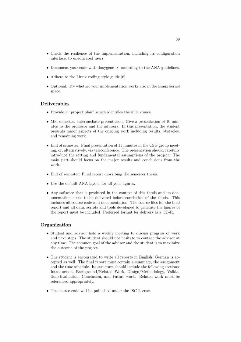
C Project Plan
Environment(Computer, Virutal Machine, IDE)
ReadingANA
Reading(Zeroconf)
Documentation(Report)
Presentation(Preparation)
Design(Protocol)
Implementation
Veri�cation/Testing
1 2 3 4 5 6 7 8
Environment(Computer, Virutal Machine, IDE)
ReadingANA
Reading(Zeroconf)
Documentation(Report)
Presentation(Preparation)
Design(Protocol)
Implementation
Veri�cation/Testing
9 10 11 12 13


![Process: rawtherapee [1806] Identifier: com.rawtherapee](https://img.pdfslide.net/doc/110x75/6281ae4b5f953d1e3374fd59/process-rawtherapee-1806-identier-comrawtherapee-.jpg)