Embed Size (px)
Citation preview
Autonomous Detection of the Loss of a Wing forUnderwater Gliders
Enrico AnderliniDepartment of Mechanical Engineering
University College LondonLondon, UK
Catherine A. HarrisMarine Autonomous and Robotic Systems
National Oceanography CentreSouthampton, UK
Georgios SalavasidisMarine Autonomous and Robotic Systems
National Oceanography CentreSouthampton, UK
Alvaro LorenzoMarine Autonomous and Robotic Systems
National Oceanography CentreSouthampton, UK
Alexander B. PhillipsMarine Autonomous and Robotic Systems
National Oceanography CentreSouthampton, UK
Giles ThomasDepartment of Mechanical Engineering
University College LondonLondon, UK
Abstract—Over the past five years, two of the Slocum under-water gliders operated by the UK National Oceanography Centrehave lost a wing mid-mission without the pilot being aware ofthe problem until the point of vehicle retrieval. In this study, thesteady-state data collected by gliders during the two deploymentshas been analysed to develop a fault detection system. From thedata analysis, it is clear that the loss of the wing was a suddenevent for both gliders. The main changes to the system dynamicsassociated with the event are an increase in the positive buoyancyof the glider and the occurrence of a roll angle on the side of thelost wing, with significant difference between dives and climbs.Hence, a simple effective system for the detection of the wing losshas been designed using the roll angle. Since sensors are knownto fail and the roll sensor is non-critical to the operation of theglider, a back-up diagnostics system has been developed basedon the dynamic model of the vehicle, capturing the change inbuoyancy. Both systems are able to correctly detect the loss ofthe wing and notify pilots, who can re-plan missions to safelyrecover the vehicle.
Index Terms—underwater glider, fault detection, fault isola-tion, system identification, wing loss
I. INTRODUCTION
Underwater gliders (UGs) are a type of autonomous under-water vehicle that are extensively used for the exploration andstudy of the oceans [1]. The vehicles achieve vertical motionin the water by changing their buoyancy through a variablebuoyancy device (VBD). Wings generate a forward motioncomponent from the vertical motion. Hence, UGs travel ina characteristic sawtooth pattern in the vertical plane. Theirsimple propulsion system, which consists of the VBD, pitchcontrol and either roll control or a rudder, is highly efficient.Therefore, although they operate at low velocities (≈ 0.3 m/s),a single UG deployment can last for several months.
The National Oceanography Centre (NOC) in the UK isdeveloping a new command-and-control system for efficientmarine autonomous systems fleet management as part of theOceanids project funded by the Industrial Strategy Challenge
C. Harris, G. Salavasidis, A. Lorenzo Lopez and A. B. Phillips contributionswere funded under the NERC/ISCF Oceanids programme.
Fund [2], [3]. The aim of the system is to facilitate the over-the-horizon operation of the ever-increasing fleet of AUVs inthe UK’s National Marine Equipment Pool, which includesover 30 UGs. As part of an on-going collaboration, theauthors have previously prototyped a recommender system tohelp pilots trim and set-up Seaglider UGs [4], [5]. In thisstudy, the aim is to address a different operational challenge:identifying when a glider loses a wing. Wings and their lockingmechanisms are not as able as the pressure hull to withstandlarge impact loads. Hence, in case of significant collisions,wings can detach from the UG body.
The reliability of UGs is analysed thoroughly in [6], withthe authors collecting failure data from most European op-erators. However, the loss of a wing was not reported as aproblem. Therefore, to our knowledge, this is the first studythat investigates the response of an UG after the loss ofone wing mid-mission. Over the past five years, two of theSlocum UGs operated by NOC have lost one wing during adeployment without the pilot noticing the event until retrieval.In this article, the data from those deployments is analysedto investigate the impact of the loss of wing on the dynamicsof the vehicle. A simple but effective rule- and model-based,remote, real-time fault detection method is then developed.
II. SLOCUM GLIDERS DATA
A. Slocum Underwater Gliders
Slocum is a type of UGs manufactured by Teledyne WebbResearch that have been in operation since the late nineties[7], [8]. The Slocum G2 [9], the second version of the UG,is considered in this study to match the type of vehicles thatlost a wing. In particular, the analysed UGs are rated for amaximum depth of 200 m. As shown in Fig. 1, the Slocumsare actuated by a VBD, which consists in an oil bladder thatcan be extended or retracted from the pressure hull. When thebladder is outside the pressure hull, the vehicle’s displacementincreases and so does its net buoyancy and vice versa. Thevehicles considered in this study are limited to changes in the
VBD volume of ±250 cm3. Furthermore, pitch is controlledby shifting the position of one movable battery pack witha dedicated mechanism. Yaw is controlled through a rudder,which is magnetically coupled to a servo motor to avoid anopening in the pressure hull.
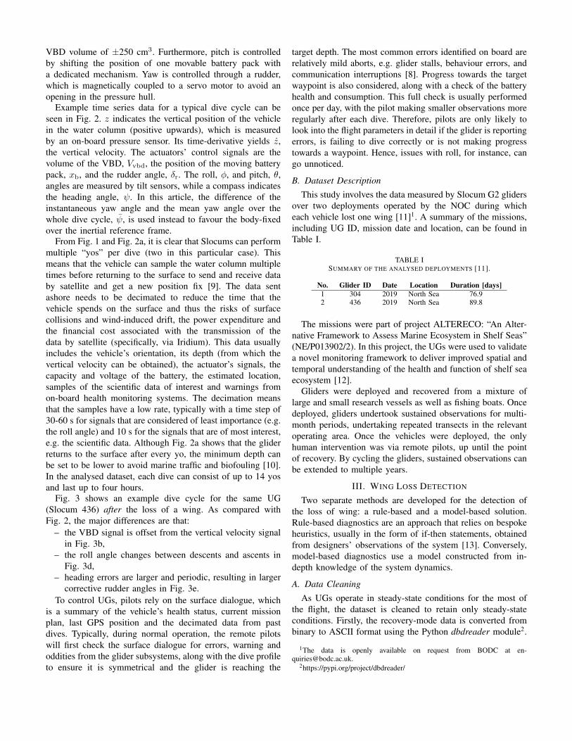
Example time series data for a typical dive cycle can beseen in Fig. 2. z indicates the vertical position of the vehiclein the water column (positive upwards), which is measuredby an on-board pressure sensor. Its time-derivative yields z,the vertical velocity. The actuators’ control signals are thevolume of the VBD, Vvbd, the position of the moving batterypack, xb, and the rudder angle, δr. The roll, φ, and pitch, θ,angles are measured by tilt sensors, while a compass indicatesthe heading angle, ψ. In this article, the difference of theinstantaneous yaw angle and the mean yaw angle over thewhole dive cycle, ψ, is used instead to favour the body-fixedover the inertial reference frame.
From Fig. 1 and Fig. 2a, it is clear that Slocums can performmultiple “yos” per dive (two in this particular case). Thismeans that the vehicle can sample the water column multipletimes before returning to the surface to send and receive databy satellite and get a new position fix [9]. The data sentashore needs to be decimated to reduce the time that thevehicle spends on the surface and thus the risks of surfacecollisions and wind-induced drift, the power expenditure andthe financial cost associated with the transmission of thedata by satellite (specifically, via Iridium). This data usuallyincludes the vehicle’s orientation, its depth (from which thevertical velocity can be obtained), the actuator’s signals, thecapacity and voltage of the battery, the estimated location,samples of the scientific data of interest and warnings fromon-board health monitoring systems. The decimation meansthat the samples have a low rate, typically with a time step of30-60 s for signals that are considered of least importance (e.g.the roll angle) and 10 s for the signals that are of most interest,e.g. the scientific data. Although Fig. 2a shows that the gliderreturns to the surface after every yo, the minimum depth canbe set to be lower to avoid marine traffic and biofouling [10].In the analysed dataset, each dive can consist of up to 14 yosand last up to four hours.
Fig. 3 shows an example dive cycle for the same UG(Slocum 436) after the loss of a wing. As compared withFig. 2, the major differences are that:
– the VBD signal is offset from the vertical velocity signalin Fig. 3b,
– the roll angle changes between descents and ascents inFig. 3d,
– heading errors are larger and periodic, resulting in largercorrective rudder angles in Fig. 3e.
To control UGs, pilots rely on the surface dialogue, whichis a summary of the vehicle’s health status, current missionplan, last GPS position and the decimated data from pastdives. Typically, during normal operation, the remote pilotswill first check the surface dialogue for errors, warning andoddities from the glider subsystems, along with the dive profileto ensure it is symmetrical and the glider is reaching the
target depth. The most common errors identified on board arerelatively mild aborts, e.g. glider stalls, behaviour errors, andcommunication interruptions [8]. Progress towards the targetwaypoint is also considered, along with a check of the batteryhealth and consumption. This full check is usually performedonce per day, with the pilot making smaller observations moreregularly after each dive. Therefore, pilots are only likely tolook into the flight parameters in detail if the glider is reportingerrors, is failing to dive correctly or is not making progresstowards a waypoint. Hence, issues with roll, for instance, cango unnoticed.
B. Dataset Description
This study involves the data measured by Slocum G2 glidersover two deployments operated by the NOC during whicheach vehicle lost one wing [11]1. A summary of the missions,including UG ID, mission date and location, can be found inTable I.
TABLE ISUMMARY OF THE ANALYSED DEPLOYMENTS [11].
No. Glider ID Date Location Duration [days]1 304 2019 North Sea 76.92 436 2019 North Sea 89.8
The missions were part of project ALTERECO: “An Alter-native Framework to Assess Marine Ecosystem in Shelf Seas”(NE/P013902/2). In this project, the UGs were used to validatea novel monitoring framework to deliver improved spatial andtemporal understanding of the health and function of shelf seaecosystem [12].
Gliders were deployed and recovered from a mixture oflarge and small research vessels as well as fishing boats. Oncedeployed, gliders undertook sustained observations for multi-month periods, undertaking repeated transects in the relevantoperating area. Once the vehicles were deployed, the onlyhuman intervention was via remote pilots, up until the pointof recovery. By cycling the gliders, sustained observations canbe extended to multiple years.
III. WING LOSS DETECTION
Two separate methods are developed for the detection ofthe loss of wing: a rule-based and a model-based solution.Rule-based diagnostics are an approach that relies on bespokeheuristics, usually in the form of if-then statements, obtainedfrom designers’ observations of the system [13]. Conversely,model-based diagnostics use a model constructed from in-depth knowledge of the system dynamics.
A. Data Cleaning
As UGs operate in steady-state conditions for the most ofthe flight, the dataset is cleaned to retain only steady-stateconditions. Firstly, the recovery-mode data is converted frombinary to ASCII format using the Python dbdreader module2.
1The data is openly available on request from BODC at [email protected].
2https://pypi.org/project/dbdreader/
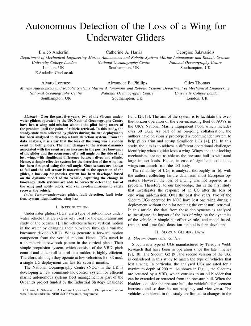
Glider reduces its buoyancy through the VBD and obtains a negative pitch angle by shifting the battery forward
to initiate the descent.
At the apogee, the glider extends the VBD to increase its buoyancy and shifts the battery aft to initiate the climb.
Slocum gliders can perform multiple “yos” per dive. This means that they do not have to emerge after every yo. After the dive, the vehicle emerges to
get a position fix via GPS, send the decimated data back to shore and receive a new mission command from the remote pilot. Before a new dive, a new GPS fix is obtained to better estimate surface currents.
Wings provide a horizontal motion
component.
Dive
Yo Yo
Fig. 1. Diagram showing the concept of operation of a Slocum UG. The drawing is not to scale: the analysed vehicles reach their apogee at 200-m-depthand and have glide path angles with a magnitude in the range (15, 30).
descent ascent
Fig. 2. Example dive cycle of an intact Slocum glider.
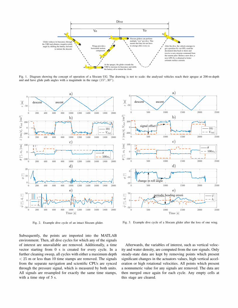
Subsequently, the points are imported into the MATLABenvironment. Then, all dive cycles for which any of the signalsof interest are unavailable are removed. Additionally, a timevector starting from 0 s is created for every cycle. In afurther cleaning sweep, all cycles with either a maximum depth< 25 m or less than 10 time stamps are removed. The signalsfrom the separate navigation and scientific CPUs are syncedthrough the pressure signal, which is measured by both units.All signals are resampled for exactly the same time stamps,with a time step of 5 s.
signal offset
change in roll angle
periodic heading errors
descent ascent
Fig. 3. Example dive cycle of a Slocum glider after the loss of one wing.
Afterwards, the variables of interest, such as vertical veloc-ity and water density, are computed from the raw signals. Onlysteady-state data are kept by removing points which presentsignificant changes in the actuators values, high vertical accel-eration or high rotational velocities. All points which presenta nonnumeric value for any signals are removed. The data arethen merged once again for each cycle. Any empty cells atthis stage are cleared.
B. Rule-Based DiagnosticsFrom the analysis of Fig. 2 and Fig. 3, the clearest indicator
of the loss of a wing is recognised as the difference in thevalue of the roll angle between dives and climbs, as describedin Sec. II. Since the roll angle is stationary over each descentand ascent even for the damaged glider, a simple but effectiveinitial tool for the detection of the wing loss can be created byaveraging the roll angle over the descent and ascent of all yosin each cycle. Hence, the difference of the mean steady-stateroll angle in ascents and descents in a single dive can be usedas an indicator of wing loss:
∆mean(φ) = φa − φd, (1)
where φa and φd indicate the mean roll angle in ascents anddescents, respectively. The threshold value for the indicatorwill be identified in Sec. IV.
This method is highly effective and computationally inex-pensive. However, as the data relies on a single sensor, the tiltsensor for roll, the scheme is susceptible to sensor calibrationand malfunction. For instance, the failure of the pitch tiltsensor was observed in [14] for a Seaglider UG. Therefore,alternative back-up methods that rely on different sensors arerequired.
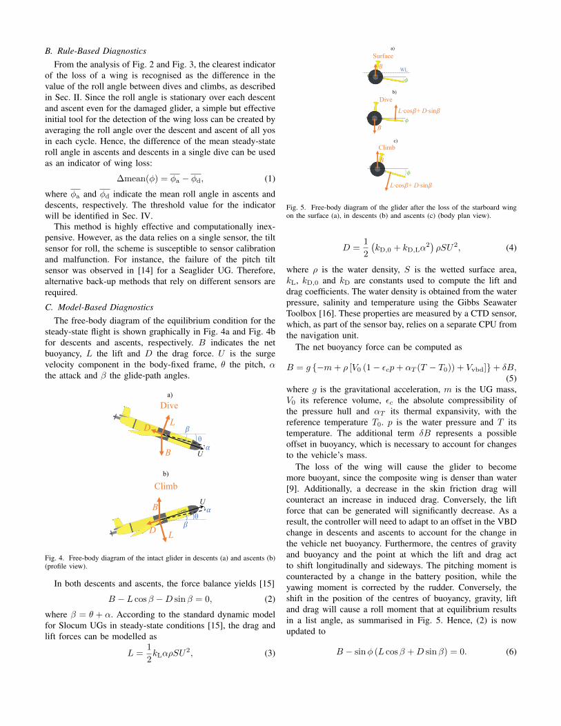
C. Model-Based DiagnosticsThe free-body diagram of the equilibrium condition for the
steady-state flight is shown graphically in Fig. 4a and Fig. 4bfor descents and ascents, respectively. B indicates the netbuoyancy, L the lift and D the drag force. U is the surgevelocity component in the body-fixed frame, θ the pitch, αthe attack and β the glide-path angles.
B !U
"θ
D L
Divea)
D L
B U
"!
θ
Climbb)
SurfaceB WL
#
a)
B
L·cos!+ D·sin!#
Diveb)
Climb
B
L·cos!+ D·sin!#
c)
Fig. 4. Free-body diagram of the intact glider in descents (a) and ascents (b)(profile view).
In both descents and ascents, the force balance yields [15]
B − L cosβ −D sinβ = 0, (2)
where β = θ + α. According to the standard dynamic modelfor Slocum UGs in steady-state conditions [15], the drag andlift forces can be modelled as
L =1
2kLαρSU
2, (3)
B !U
"θ
D L
Divea)
D L
B U
"!
θ
Climbb)
SurfaceB WL
#
a)
B
L·cos!+ D·sin!#
Diveb)
Climb
B
L·cos!+ D·sin!#
c)
Fig. 5. Free-body diagram of the glider after the loss of the starboard wingon the surface (a), in descents (b) and ascents (c) (body plan view).
D =1
2
(kD,0 + kD,Lα
2)ρSU2, (4)
where ρ is the water density, S is the wetted surface area,kL, kD,0 and kD are constants used to compute the lift anddrag coefficients. The water density is obtained from the waterpressure, salinity and temperature using the Gibbs SeawaterToolbox [16]. These properties are measured by a CTD sensor,which, as part of the sensor bay, relies on a separate CPU fromthe navigation unit.
The net buoyancy force can be computed as
B = g −m+ ρ [V0 (1− εcp+ αT (T − T0)) + Vvbd]+ δB,(5)
where g is the gravitational acceleration, m is the UG mass,V0 its reference volume, εc the absolute compressibility ofthe pressure hull and αT its thermal expansivity, with thereference temperature T0. p is the water pressure and T itstemperature. The additional term δB represents a possibleoffset in buoyancy, which is necessary to account for changesto the vehicle’s mass.
The loss of the wing will cause the glider to becomemore buoyant, since the composite wing is denser than water[9]. Additionally, a decrease in the skin friction drag willcounteract an increase in induced drag. Conversely, the liftforce that can be generated will significantly decrease. As aresult, the controller will need to adapt to an offset in the VBDchange in descents and ascents to account for the change inthe vehicle net buoyancy. Furthermore, the centres of gravityand buoyancy and the point at which the lift and drag actto shift longitudinally and sideways. The pitching moment iscounteracted by a change in the battery position, while theyawing moment is corrected by the rudder. Conversely, theshift in the position of the centres of buoyancy, gravity, liftand drag will cause a roll moment that at equilibrium resultsin a list angle, as summarised in Fig. 5. Hence, (2) is nowupdated to
B − sinφ (L cosβ +D sinβ) = 0. (6)
Ideally, the fault detection system should be able to identifyproblems other than purely the loss of wings. Hence, to ensuregenerality, the system will be based on the established dynamicmodel for Slocum UGs to predict the steady-state verticalvelocity considering only motions in surge, heave and pitch.Substituting (3), (4) and (5) into (2), it is possible to expressthe vertical velocity predicted by the model, zm, as follows[15]:
zm =√U2 sinβ, where (7a)
U2 =B sinβ
0.5ρS (kD,0 + kD,Lα2), (7b)
α =kD,0 + kD,Lα
2
kL tan (β). (7c)
Equation (7c) requires an iterative solution. Additionally, anoptimisation needs to be run to find the desired parameters.The cost function is expressed as:
J =
[1
I
I∑i=1
(zi − zm,i)2 ∀ i ∈ R
]+
J∑j=1
j ∀ j /∈ R
. (8)
In (8), i indicate all points for which a numeric cost value isobtained, while j all points for which U2 < 0. Imposing anadditional cost on the number of nonnumeric values speedsup convergence as compared with Merckelbach, et al. [15].
The values for some parameters are known; namely, g =9.81 m/s2, εc = 6.4×10⁻⁶ dbar−1 and αT = 5.3×10⁻⁵ C−1
for Slocum G2 UGs (from the manufacturer), S = 0.1 m2 [15],and m, V0 and T0 are measured during the ballasting tests ina tank before each deployment. The values for the analysedUGs are shown in Table II. Therefore, the optimisation is runto find the values of the parameters kL, kD,0, kD,L and δB.
TABLE IISUMMARY OF THE HYDROSTATICS FOR THE ANALYSED SLOCUM UGS.
Glider ID m [kg] V0 [cm3] T0 [C]304 59.044 57615.8 19.23436 65.281 63716.5 19.45
From a fault detection perspective, it is interesting totrack changes over each individual dive cycle. Although it ispossible to solve for kL, kD,0, kD,L and δB simultaneously[15], the range of vertical velocity and pitch angle values inindividual dive cycles (even if consisting of multiple yos) isunlikely to be comprehensive. A much larger dataset (usuallyover the whole deployment) is typically needed to obtain allparameters [15]. Hence, the values of the lift and induced dragcoefficients are preset to values found in [15]: kL = 7.5 rad−1
and kD,L = 3 rad−2 for Slocum G2 UGs. Then, a globalsearch optimisation is run to find kD,0 and δB for each divecycle. A scatter search [17] is used to generate trial pointswithin the search space from which a constrained, nonlinearprogramming solution is found based on a trust region methodbased on interior point techniques [18]. The scatter searchalgorithm then assesses the cost function of the solutionsto update the trial points and continue the minimisation
until convergence onto the global optimum. The MATLABGlobalSearch and fmincon tools were used in the practicalimplementation, with default settings. The drag coefficient andbuoyancy offset values were constrained to kD,0 ∈ [0, 0.4] andδB ∈ [−3, 3] N, respectively.
IV. RESULTS AND DISCUSSION
A. Wing Loss Detection
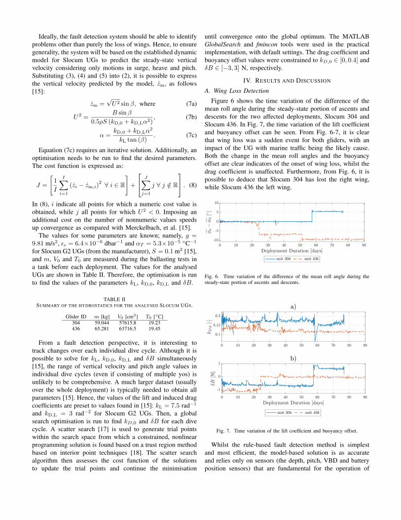
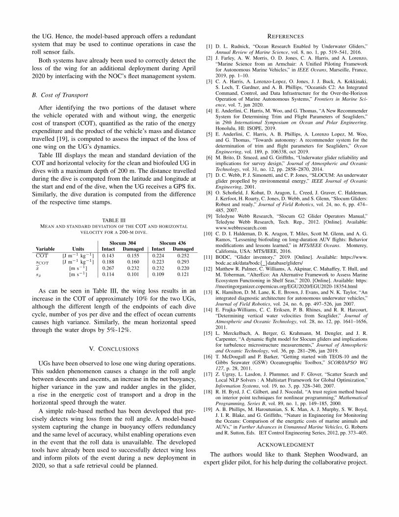
Figure 6 shows the time variation of the difference of themean roll angle during the steady-state portion of ascents anddescents for the two affected deployments, Slocum 304 andSlocum 436. In Fig. 7, the time variation of the lift coefficientand buoyancy offset can be seen. From Fig. 6-7, it is clearthat wing loss was a sudden event for both gliders, with animpact of the UG with marine traffic being the likely cause.Both the change in the mean roll angles and the buoyancyoffset are clear indicators of the onset of wing loss, whilst thedrag coefficient is unaffected. Furthermore, from Fig. 6, it ispossible to deduce that Slocum 304 has lost the right wing,while Slocum 436 the left wing.
Fig. 6. Time variation of the difference of the mean roll angle during thesteady-state portion of ascents and descents.
Fig. 7. Time variation of the lift coefficient and buoyancy offset.
Whilst the rule-based fault detection method is simplestand most efficient, the model-based solution is as accurateand relies only on sensors (the depth, pitch, VBD and batteryposition sensors) that are fundamental for the operation of
the UG. Hence, the model-based approach offers a redundantsystem that may be used to continue operations in case theroll sensor fails.
Both systems have already been used to correctly detect theloss of the wing for an additional deployment during April2020 by interfacing with the NOC’s fleet management system.
B. Cost of Transport
After identifying the two portions of the dataset wherethe vehicle operated with and without wing, the energeticcost of transport (COT), quantified as the ratio of the energyexpenditure and the product of the vehicle’s mass and distancetravelled [19], is computed to assess the impact of the loss ofone wing on the UG’s dynamics.
Table III displays the mean and standard deviation of theCOT and horizontal velocity for the clean and biofouled UG indives with a maximum depth of 200 m. The distance travelledduring the dive is computed from the latitude and longitude atthe start and end of the dive, when the UG receives a GPS fix.Similarly, the dive duration is computed from the differenceof the respective time stamps.
TABLE IIIMEAN AND STANDARD DEVIATION OF THE COT AND HORIZONTAL
VELOCITY FOR A 200-M DIVE.
Slocum 304 Slocum 436Variable Units Intact Damaged Intact DamagedCOT [J m−1 kg−1] 0.143 0.155 0.224 0.252sCOT [J m−1 kg−1] 0.188 0.160 0.223 0.293x [m s−1] 0.267 0.232 0.232 0.220sx [m s−1] 0.114 0.101 0.109 0.121
As can be seen in Table III, the wing loss results in anincrease in the COT of approximately 10% for the two UGs,although the different length of the endpoints of each divecycle, number of yos per dive and the effect of ocean currentscauses high variance. Similarly, the mean horizontal speedthrough the water drops by 5%-12%.
V. CONCLUSIONS
UGs have been observed to lose one wing during operations.This sudden phenomenon causes a change in the roll anglebetween descents and ascents, an increase in the net buoyancy,higher variance in the yaw and rudder angles in the glider,a rise in the energetic cost of transport and a drop in thehorizontal speed through the water.
A simple rule-based method has been developed that pre-cisely detects wing loss from the roll angle. A model-basedsystem capturing the change in buoyancy offers redundancyand the same level of accuracy, whilst enabling operations evenin the event that the roll data is unavailable. The developedtools have already been used to successfully detect wing lossand inform pilots of the event during a new deployment in2020, so that a safe retrieval could be planned.
REFERENCES
[1] D. L. Rudnick, “Ocean Research Enabled by Underwater Gliders,”Annual Review of Marine Science, vol. 8, no. 1, pp. 519–541, 2016.
[2] J. Farley, A. W. Morris, O. D. Jones, C. A. Harris, and A. Lorenzo,“Marine Science from an Armchair: A Unified Piloting Frameworkfor Autonomous Marine Vehicles,” in IEEE Oceans, Marseille, France,2019, pp. 1–10.
[3] C. A. Harris, A. Lorenzo-Lopez, O. Jones, J. J. Buck, A. Kokkinaki,S. Loch, T. Gardner, and A. B. Phillips, “Oceanids C2: An IntegratedCommand, Control, and Data Infrastructure for the Over-the-HorizonOperation of Marine Autonomous Systems,” Frontiers in Marine Sci-ence, vol. 7, jun 2020.
[4] E. Anderlini, C. Harris, M. Woo, and G. Thomas, “A New RecommenderSystem for Determining Trim and Flight Parameters of Seagliders,”in 29th International Symposium on Ocean and Polar Engineering.Honolulu, HI: ISOPE, 2019.
[5] E. Anderlini, C. Harris, A. B. Phillips, A. Lorenzo Lopez, M. Woo,and G. Thomas, “Towards autonomy: A recommender system for thedetermination of trim and flight parameters for Seagliders,” OceanEngineering, vol. 189, p. 106338, oct 2019.
[6] M. Brito, D. Smeed, and G. Griffiths, “Underwater glider reliability andimplications for survey design,” Journal of Atmospheric and OceanicTechnology, vol. 31, no. 12, pp. 2858–2870, 2014.
[7] D. C. Webb, P. J. Simonetti, and C. P. Jones, “SLOCUM: An underwaterglider propelled by environmental energy,” IEEE Journal of OceanicEngineering, 2001.
[8] O. Schofield, J. Kohut, D. Aragon, L. Creed, J. Graver, C. Haldeman,J. Kerfoot, H. Roarty, C. Jones, D. Webb, and S. Glenn, “Slocum Gliders:Robust and ready,” Journal of Field Robotics, vol. 24, no. 6, pp. 474–485, 2007.
[9] Teledyne Webb Research, “Slocum G2 Glider Operators Manual,”Teledyne Webb Research, Tech. Rep., 2012. [Online]. Available:www.webbresearch.com
[10] C. D. I. Haldeman, D. K. Aragon, T. Miles, Scott M. Glenn, and A. G.Ramos, “Lessening biofouling on long-duration AUV flights: Behaviormodifications and lessons learned,” in MTS/IEEE Oceans. Monterey,California, USA: MTS/IEEE, 2016.
[11] BODC, “Glider inventory,” 2019. [Online]. Available: https://www.bodc.ac.uk/data/bodc database/gliders/
[12] Matthew R. Palmer, C. Williams, A. Akpinar, C. Mahaffey, T. Hull, andM. Toberman, “AlterEco: An Alternative Framework to Assess MarineEcosystem Functioning in Shelf Seas,” 2020. [Online]. Available: https://meetingorganizer.copernicus.org/EGU2020/EGU2020-18354.html
[13] K. Hamilton, D. M. Lane, K. E. Brown, J. Evans, and N. K. Taylor, “Anintegrated diagnostic architecture for autonomous underwater vehicles,”Journal of Field Robotics, vol. 24, no. 6, pp. 497–526, jun 2007.
[14] E. Frajka-Williams, C. C. Eriksen, P. B. Rhines, and R. R. Harcourt,“Determining vertical water velocities from Seaglider,” Journal ofAtmospheric and Oceanic Technology, vol. 28, no. 12, pp. 1641–1656,2011.
[15] L. Merckelbach, A. Berger, G. Krahmann, M. Dengler, and J. R.Carpenter, “A dynamic flight model for Slocum gliders and implicationsfor turbulence microstructure measurements,” Journal of Atmosphericand Oceanic Technology, vol. 36, pp. 281–296, jan 2019.
[16] T. McDougall and P. Barker, “Getting started with TEOS-10 and theGibbs Seawater (GSW) Oceanographic Toolbox,” SCOR/IAPSO WG127, p. 28, 2011.
[17] Z. Ugray, L. Lasdon, J. Plummer, and F. Glover, “Scatter Search andLocal NLP Solvers : A Multistart Framework for Global Optimization,”Information Systems, vol. 19, no. 3, pp. 328–340, 2007.
[18] R. H. Byrd, J. C. Gilbert, and J. Nocedal, “A trust region method basedon interior point techniques for nonlinear programming,” MathematicalProgramming, Series B, vol. 89, no. 1, pp. 149–185, 2000.
[19] A. B. Phillips, M. Haroutunian, S. K. Man, A. J. Murphy, S. W. Boyd,J. I. R. Blake, and G. Griffiths, “Nature in Engineering for Monitoringthe Oceans: Comparison of the energetic costs of marine animals andAUVs,” in Further Advances in Unmanned Marine Vehicles, G. Robertsand R. Sutton, Eds. IET Control Engineering Series, 2012, pp. 373–405.
ACKNOWLEDGMENT
The authors would like to thank Stephen Woodward, anexpert glider pilot, for his help during the collaborative project.