Embed Size (px)
Citation preview
Autonomous Navigation Using Celestial Object Measurements for a CubeSat Lunar Mission
Danner Friend and
Jacques Beneat David Crawford School of Engineering
Norwich University
Presented at the 2nd Interplanetary CubeSat Workshop Ithaca, NY
May 29, 2013
Outline Background and Motivation Optical Sensors for Lunar Mission Autonomous Navigation Flowchart Measurement Options and Models used in the
Navigation Software Simulation Studies Image Processing and Image Testing Student Participation Summary
Funding through the Vermont Space Grant Consortium (VSGC), a NASA sponsored program to promote research infrastructure within the state, encourage Vermont students to engage more in mathematics and science, and promote consideration of careers in aerospace-related areas.
Norwich University is working in collaboration with Vermont Technical College
and the University of Vermont on a CubeSat project that focuses on autonomous navigation in space for missions beyond earth orbit.
Vermont Technical College is leading an effort to build a single CubeSat
scheduled in Fall 2013 to launch into low earth orbit to do some initial testing of the navigation system using a camera to capture images of the moon and stars.
Long term goal is to design a navigation system for a three axis stabilized, 3U
CubeSat on a Lunar Mission. NASA’s GEONS (GPS Enhanced Onboard Navigation System) software is being used in the navigation system. Norwich University is working on the attitude and orbit determination using optical sensors and celestial navigation capability in GEONS.
Background and Motivation
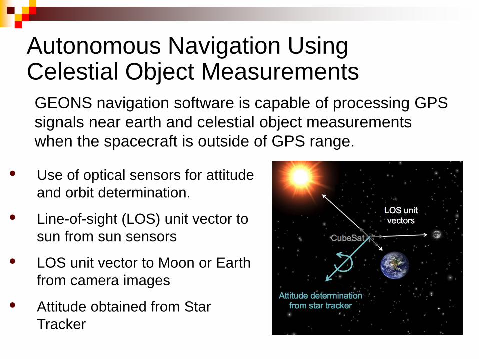
Autonomous Navigation Using Celestial Object Measurements
• Use of optical sensors for attitude and orbit determination.
• Line-of-sight (LOS) unit vector to sun from sun sensors
• LOS unit vector to Moon or Earth from camera images
• Attitude obtained from Star Tracker
GEONS navigation software is capable of processing GPS signals near earth and celestial object measurements when the spacecraft is outside of GPS range.
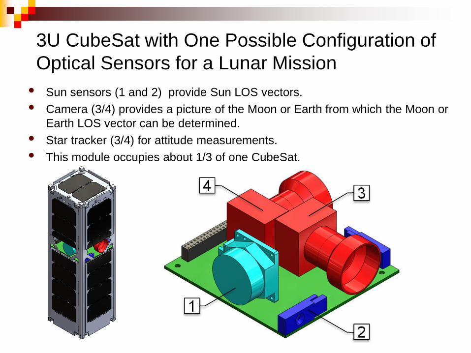
3U CubeSat with One Possible Configuration of Optical Sensors for a Lunar Mission
• Sun sensors (1 and 2) provide Sun LOS vectors. • Camera (3/4) provides a picture of the Moon or Earth from which the Moon or
Earth LOS vector can be determined. • Star tracker (3/4) for attitude measurements. • This module occupies about 1/3 of one CubeSat.
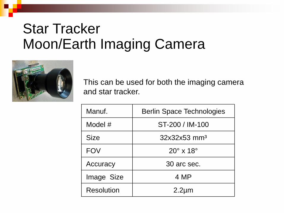
Manuf. Berlin Space Technologies
Model # ST-200 / IM-100
Size 32x32x53 mm³
FOV 20° x 18°
Accuracy 30 arc sec.
Image Size 4 MP
Resolution 2.2µm
This can be used for both the imaging camera and star tracker.
Star Tracker Moon/Earth Imaging Camera
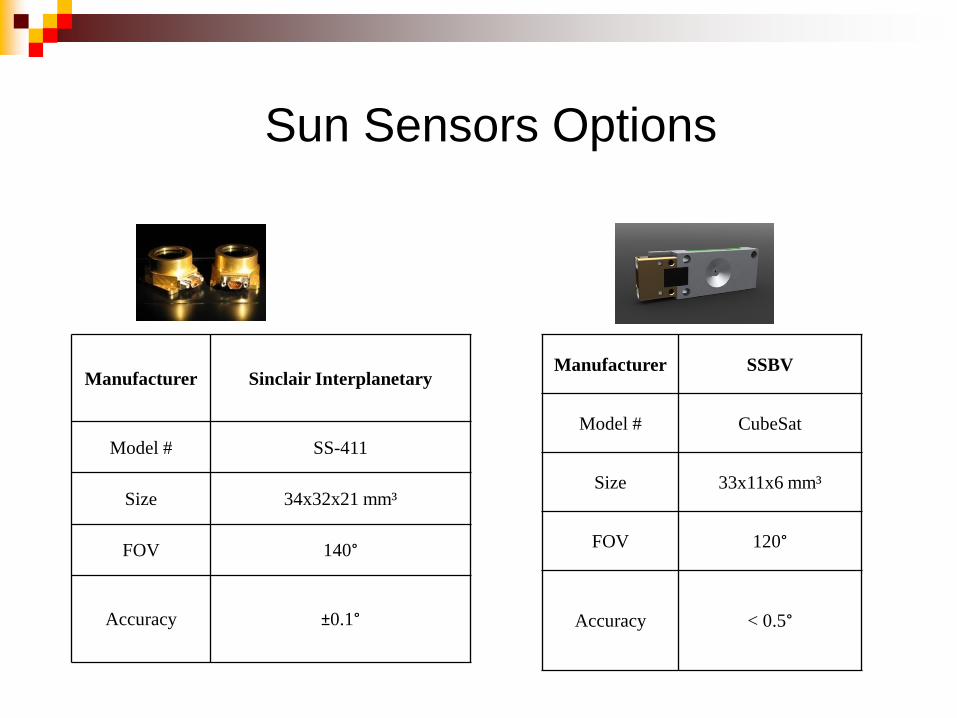
Sun Sensors Options
Manufacturer Sinclair Interplanetary
Model # SS-411
Size 34x32x21 mm³
FOV 140°
Accuracy ±0.1°
Manufacturer SSBV
Model # CubeSat
Size 33x11x6 mm³
FOV 120°
Accuracy < 0.5°
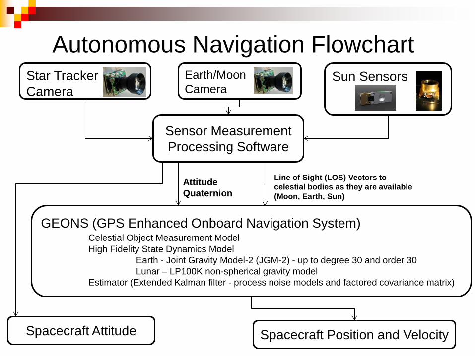
Autonomous Navigation Flowchart Star Tracker Camera
Earth/Moon Camera
Sun Sensors
Sensor Measurement Processing Software
Line of Sight (LOS) Vectors to celestial bodies as they are available (Moon, Earth, Sun)
Attitude Quaternion
GEONS (GPS Enhanced Onboard Navigation System) Celestial Object Measurement Model High Fidelity State Dynamics Model Earth - Joint Gravity Model-2 (JGM-2) - up to degree 30 and order 30 Lunar – LP100K non-spherical gravity model Estimator (Extended Kalman filter - process noise models and factored covariance matrix)
Spacecraft Position and Velocity Spacecraft Attitude
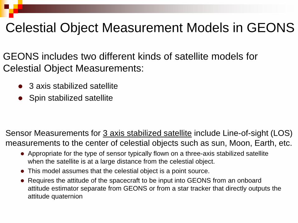
GEONS includes two different kinds of satellite models for Celestial Object Measurements:
3 axis stabilized satellite Spin stabilized satellite
Celestial Object Measurement Models in GEONS
Appropriate for the type of sensor typically flown on a three-axis stabilized satellite
when the satellite is at a large distance from the celestial object. This model assumes that the celestial object is a point source. Requires the attitude of the spacecraft to be input into GEONS from an onboard
attitude estimator separate from GEONS or from a star tracker that directly outputs the attitude quaternion
Sensor Measurements for 3 axis stabilized satellite include Line-of-sight (LOS) measurements to the center of celestial objects such as sun, Moon, Earth, etc.
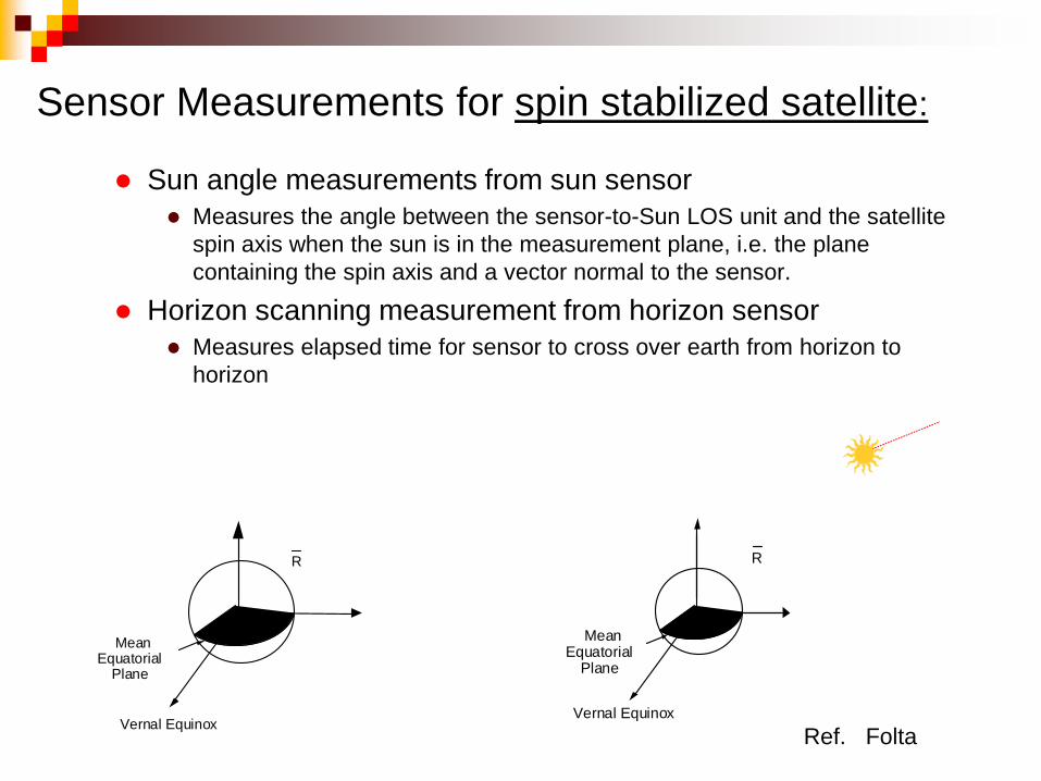
Sensor Measurements for spin stabilized satellite:
Sun angle measurements from sun sensor Measures the angle between the sensor-to-Sun LOS unit and the satellite
spin axis when the sun is in the measurement plane, i.e. the plane containing the spin axis and a vector normal to the sensor.
Horizon scanning measurement from horizon sensor Measures elapsed time for sensor to cross over earth from horizon to
horizon
Vernal Equinox
Mean Equatorial
Plane
R
Vernal Equinox
Mean Equatorial
Plane
R
Ref. Folta
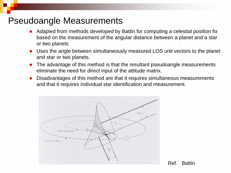
Pseudoangle Measurements Adapted from methods developed by Battin for computing a celestial position fix
based on the measurement of the angular distance between a planet and a star or two planets
Uses the angle between simultaneously measured LOS unit vectors to the planet and star or two planets.
The advantage of this method is that the resultant pseudoangle measurements eliminate the need for direct input of the attitude matrix.
Disadvantages of this method are that it requires simultaneous measurements and that it requires individual star identification and measurement.
Ref. Battin
Choice of Celestial Object Measurement Model for CubeSat Lunar Mission
Best choice is the 3 axis stabilized measurement model using Line-of-sight vectors CubeSat on Lunar Mission will be 3 axis stabilized. Availability of a COTS CubeSat-sized star tracker for direct input of attitude quaternion. Proximity of Moon lends itself to using a camera for determining LOS vector to Moon. LOS to sun from sun sensor At a sufficient distance away from Earth, the same camera for Moon sensing can be
used for LOS vector to Earth
Summary of GEONS Required Input for Implementing Celestial Object Measurements using the 3 Axis stabilized satellite model
Line-of-Sight Unit Vectors Components of Line-of-Site unit vectors from satellite to celestial object
given in the Earth Centered Inertial (ECI) coordinate frame.
Attitude The attitude (from the star tracker) is input in the quaternion format
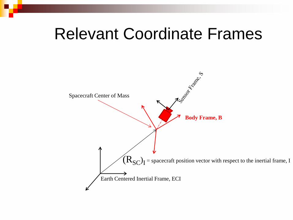
Earth Centered Inertial Frame, ECI
Body Frame, B
Spacecraft Center of Mass
(RSC)I = spacecraft position vector with respect to the inertial frame, I
Relevant Coordinate Frames
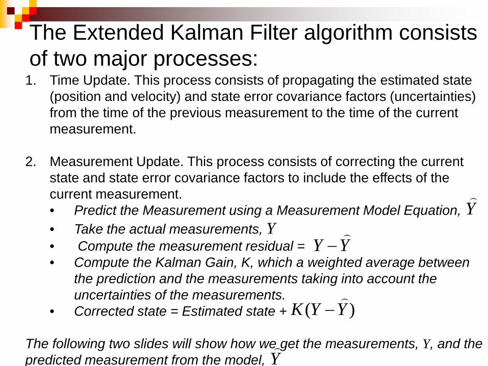
1. Time Update. This process consists of propagating the estimated state
(position and velocity) and state error covariance factors (uncertainties) from the time of the previous measurement to the time of the current measurement.
2. Measurement Update. This process consists of correcting the current state and state error covariance factors to include the effects of the current measurement. • Predict the Measurement using a Measurement Model Equation, • Take the actual measurements, Y • Compute the measurement residual = • Compute the Kalman Gain, K, which a weighted average between
the prediction and the measurements taking into account the uncertainties of the measurements.
• Corrected state = Estimated state + The following two slides will show how we get the measurements, Y, and the predicted measurement from the model,
YY
−
)( YYK
−
Y
The Extended Kalman Filter algorithm consists of two major processes:
Y
Moon
B
S
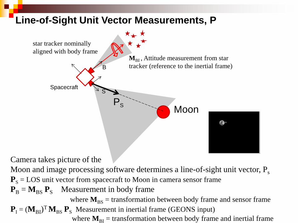
MBI , Attitude measurement from star tracker (reference to the inertial frame)
Camera takes picture of the Moon and image processing software determines a line-of-sight unit vector, Ps PS = LOS unit vector from spacecraft to Moon in camera sensor frame PB = MBS PS Measurement in body frame where MBS = transformation between body frame and sensor frame PI = (MBI)T
MBS PS Measurement in inertial frame (GEONS input) where MBI = transformation between body frame and inertial frame
PS
Spacecraft
Line-of-Sight Unit Vector Measurements, P
star tracker nominally aligned with body frame
ECI
Moon S
(RM)I
(RSC)I
(PM)I
Earth
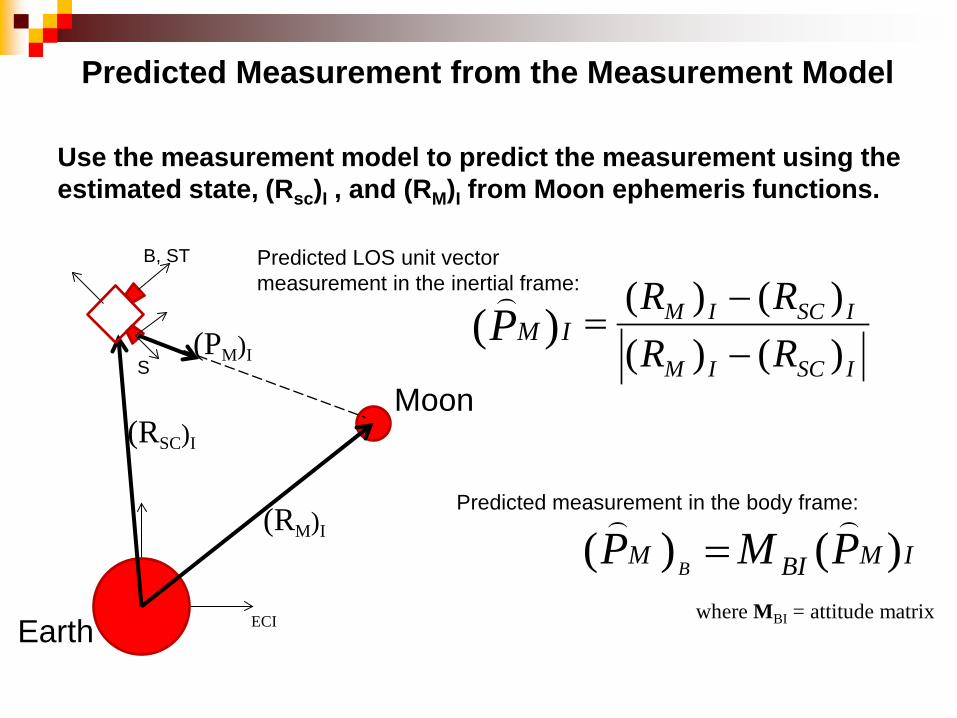
Use the measurement model to predict the measurement using the estimated state, (Rsc)I , and (RM)I from Moon ephemeris functions.
B, ST
ISCIM
ISCIM
RRRR
)()()()(
−−
=
IMBIM PMP B )()(
=
Predicted LOS unit vector measurement in the inertial frame:
Predicted measurement in the body frame:
Predicted Measurement from the Measurement Model
where MBI = attitude matrix
IMP )(
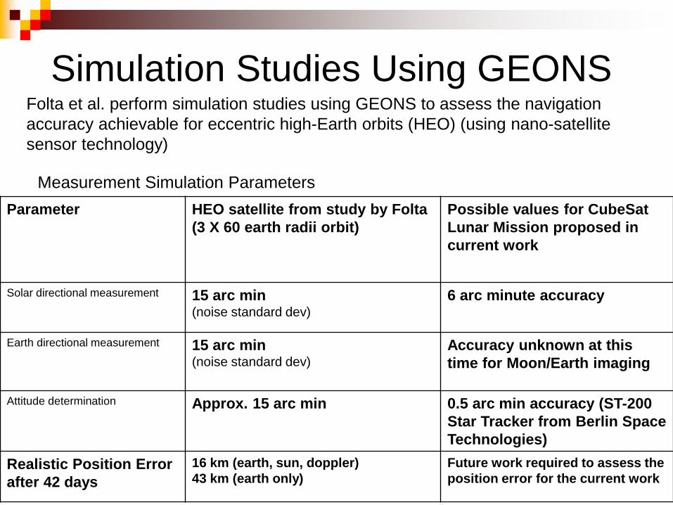
Simulation Studies Using GEONS Folta et al. perform simulation studies using GEONS to assess the navigation
accuracy achievable for eccentric high-Earth orbits (HEO) (using nano-satellite sensor technology)
Parameter HEO satellite from study by Folta
(3 X 60 earth radii orbit) Possible values for CubeSat Lunar Mission proposed in current work
Solar directional measurement 15 arc min (noise standard dev)
6 arc minute accuracy
Earth directional measurement
15 arc min (noise standard dev)
Accuracy unknown at this time for Moon/Earth imaging
Attitude determination
Approx. 15 arc min 0.5 arc min accuracy (ST-200 Star Tracker from Berlin Space Technologies)
Realistic Position Error after 42 days
16 km (earth, sun, doppler) 43 km (earth only)
Future work required to assess the position error for the current work
Measurement Simulation Parameters
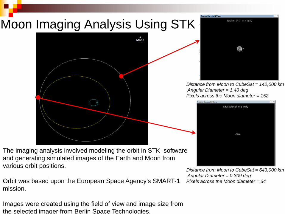
Moon Imaging Analysis Using STK
Distance from Moon to CubeSat = 142,000 km Angular Diameter = 1.40 deg Pixels across the Moon diameter = 152
Distance from Moon to CubeSat = 643,000 km Angular Diameter = 0.309 deg Pixels across the Moon diameter = 34
The imaging analysis involved modeling the orbit in STK software and generating simulated images of the Earth and Moon from various orbit positions. Orbit was based upon the European Space Agency’s SMART-1 mission. Images were created using the field of view and image size from the selected imager from Berlin Space Technologies.
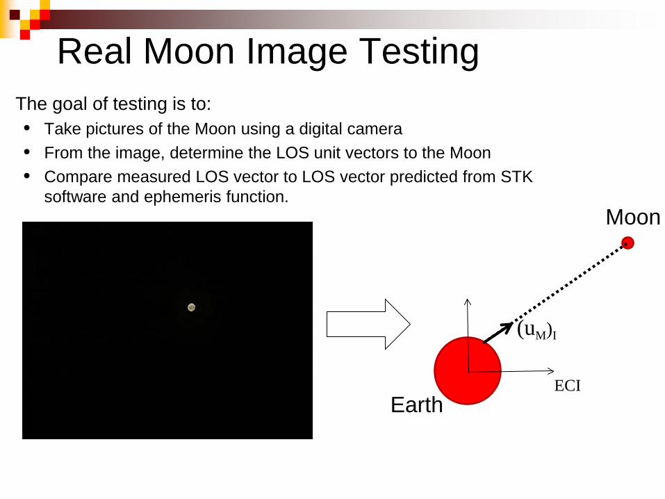
Real Moon Image Testing The goal of testing is to:
• Take pictures of the Moon using a digital camera • From the image, determine the LOS unit vectors to the Moon • Compare measured LOS vector to LOS vector predicted from STK
software and ephemeris function.
ECI
Moon
(uM)I
Earth
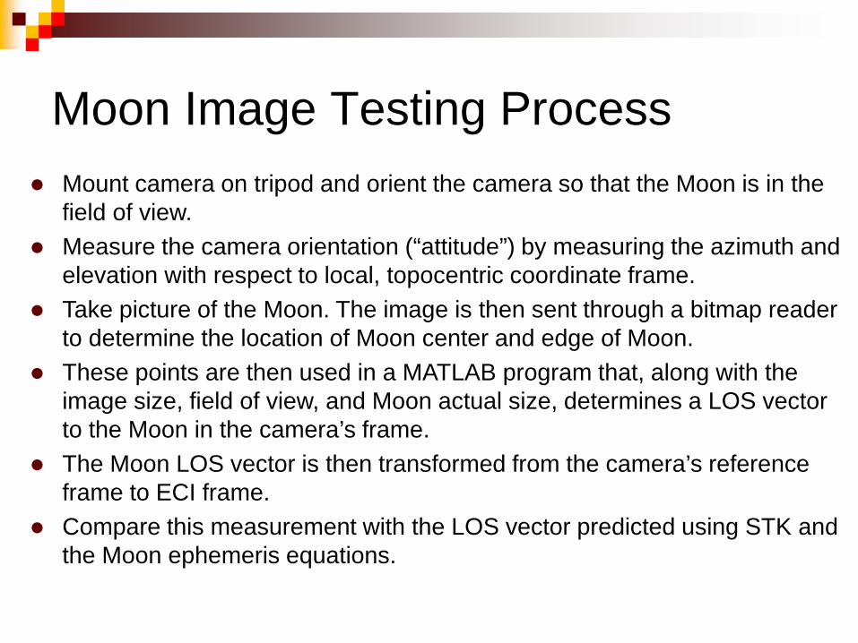
Moon Image Testing Process Mount camera on tripod and orient the camera so that the Moon is in the
field of view. Measure the camera orientation (“attitude”) by measuring the azimuth and
elevation with respect to local, topocentric coordinate frame. Take picture of the Moon. The image is then sent through a bitmap reader
to determine the location of Moon center and edge of Moon. These points are then used in a MATLAB program that, along with the
image size, field of view, and Moon actual size, determines a LOS vector to the Moon in the camera’s frame.
The Moon LOS vector is then transformed from the camera’s reference frame to ECI frame.
Compare this measurement with the LOS vector predicted using STK and the Moon ephemeris equations.
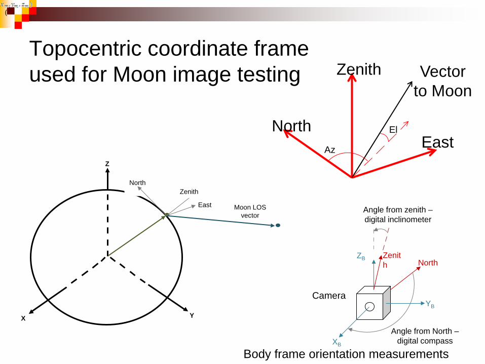
Topocentric coordinate frame used for Moon image testing
Y X
Z
Moon LOS vector
North
East
Zenith
(
Zenith
East North
Vector to Moon
El
Az
Angle from North – digital compass
Angle from zenith – digital inclinometer
Zenith North
ZB
YB
XB
Body frame orientation measurements
Camera
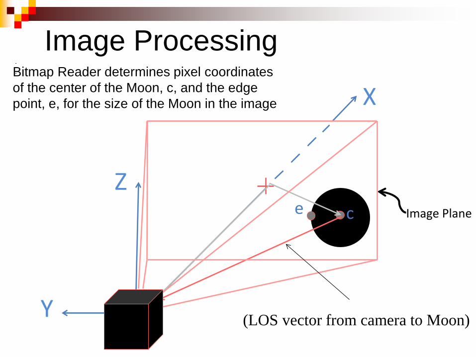
Bitmap Reader determines pixel coordinates of the center of the Moon, c, and the edge point, e, for the size of the Moon in the image
(LOS vector from camera to Moon)
Image Plane
Z
Y
X
e c
Image Processing
• Code has been written to analyze images of full Moon to determine the center and edge location of the Moon
• Code has been written to determine a Line-of-Sight vector to the center of the body.
• Code has been written to transform the Line-of-Sight vector in the sensor frame to the Topocentric frame and to the Inertial frame.
• The process and functions for predicting LOS vector from STK and from ephemeris functions have been determined.
• Moon images have been recorded and the results are currently being processed.
Status of Work on Image Testing
Work on CubeSat project started in January 2010 16 Norwich engineering students (8 Electrical/Computer and 10 Mechanical) 2 faculty mentors (Electrical/Computer and Mechanical Engineering) Three senior design projects 8 summer research students Research and Education Focus:
Autonomous navigation Celestial Navigation Sensors (cameras, star trackers, sun sensors) Image processing
Results presented at
Vermont Space Grants Awards Ceremony (2010, 2011, 2012) National Conference for Undergraduate Research (2011, 2012, 2013) ASME International Mechanical Engineering Congress and Exposition (Nov 2010)
Norwich Student Participation
Summary An initial concept of autonomous navigation using celestial
object measurements has been demonstrated for a CubeSat Lunar Mission.
Optical sensors have been selected that provide the necessary
measurement inputs into GEONS for orbit determination.
Initial image testing has begun to verify the image processing required for determining Line-of-Sight vectors to celestial bodies.
The celestial navigation concept developed in this work is applicable to interplanetary CubeSat missions for at least the segments of the mission for which near bodies such as planets, moons, and/or asteroids can be identified in images.
Future Work
Error Analysis that considers the following: Distance from S/C to celestial body (Moon, Earth, Sun) Image processing errors Ephemeris functions used for Moon, Earth, Sun (low, med, high
precision options) Choice of central body for gravity model (Earth or Moon?) Orbit Estimation and filter algorithms used
Image Processing: Consider different phases of the Moon in addition to full Moon Influence of image size and number of pixels Image processing software (edge detection, centroid finding)
Teaching Materials: Incorporation into existing courses and laboratories Considering offering technical elective on this topic
Acknowledgements Vermont Space Grant Consortium and NASA
for their support and funding for this project. AGI for the use of STK software
References Honeywell Technical Solutions Inc., Mission Operations and Mission Services, FDF-59-
019, Goddard Enhanced Onboard Navigation System (GEONS) Mathematical Specifications, Version 2, Release 2.13, Original, A. Long and T. Lee, prepared by a.i. solutions, Inc., November 2009.
R. Battin, An Introduction to the Mathematics and Methods of Astrodynamics, American
Institute of Aeronautics and Astronautics, New York, 1987 D. Folta et al., “Autonomous Navigation Using Celestial Objects,” paper AAS 99-439
presented at the AAS/AIAA Astrodynamics Specialist Conference, Girdwood, Alaska, August 16-19, 1999

Contact Information Dr. Danner Friend Mechanical Engineering Department Norwich University 158 Harmon Drive Northfield, VT 05663 [email protected]