Embed Size (px)
Citation preview

®
A/V Cinema ScalerPro I
EXT-AVCINEMAAA
User Manual

ASKING FOR ASSISTANCE
Technical Support:Telephone (818) 772-9100
(800) 545-6900
Fax (818) 772-9120
Technical Support Hours:8:00 AM to 5:00 PM Monday thru Friday PST
Write To:
Gefen, LLCc/o Customer Service20600 Nordhoff St Chatsworth, CA 91311
NoticeGefen, LLC reserves the right to make changes in the hard ware, packaging and
any accompanying doc u men ta tion without prior written notice.
A/V Cinema Scaler Pro I is a trademark of Gefen, LLC
ANALOG Version
Manufactured under license from Dolby Laboratories.“Dolby”, “Pro Logic”, and the double-D symbol are trademarks of
Dolby Laboratories.
© 2010 Gefen, LLC, All Rights ReservedAll trademarks are the property of their respective companies
Rev E33.25

CONTENTS
1 Introduction2 Operation Notes3 Features4 Panel Layout5 Panel Descriptions6 Panel Descriptions7 Front Panel Buttons7 Navigation7 Input Selection 9 Using The A/V Cinema Scaler Pro - Main LCD9 LCD Screen10 A/V Cinema Scaler Pro - Initial Startup10 Powering On 12 A/V Cinema Scaler Pro - Main Screen12 Main Display13 Input Resolutions 14 Audio Input Type 14 Audio Formats15 Sampling Rates 15 Number Of Channels15 Output Screen 16 Surround Processing17 Dynamic Range Compression17 Reference Level Compensation18 DVI Output Type18 HDMI EDID Type 19 Audio Input Type20 Product Title21 A/V Cinema Scaler Pro - Confi guration21 Main Features Menu22 A/V Cinema Scaler Pro - Picture Adjust23 Mode24 Contrast 25 Brightness25 Hue25 Saturation26 Sharpness26 Aspect Ratio 28 Noise Reduction 29 Horizontal Position29 Vertical Position 29 Clock30 Phase30 Exit Picture Adjust 30 A/V Cinema Scaler Pro - Color Adjust31 Color Temp32 Red33 Green

33 Blue 33 Exit Color Adjust34 A/V Cinema Scaler Pro - Lipsync Delay Adjust34 Lipsync Delay 34 Exit Lipsync Adjust 35 A/V Cinema Scaler Pro - Surround Delay Adjust35 Surround Right Delay 36 Rear Surround Right Delay36 Rear Surround Left Delay36 Exit Lipsync Adjust 37 A/V Cinema Scaler Pro - Output Selection37 Output Timing 1080P 38 Output Timing 2K 38 Exit Output Selection38 A/V Cinema Scaler Pro - On Screen Display Adjust39 Horizontal Position 40 Vertical Position 40 Timeout 40 Background 41 Exit OSD Adjust41 A/V Cinema Scaler Pro - Firmware42 DB-25 Audio Input & Bypass Mode42 A/V Cinema Scaler Pro - DB-25 Audio Bypass Mode42 Enabling Bypass Mode 43 Analog Input And Output Pinout44 Analog DB-25 Output44 Analog DB-25 Input45 RS-232 Serial Control Interface45 RS-232 Settings 46 RS-232 Serial Control Commands48 Rack Mount / Tabletop Installation49 Specifi cations52 Warranty
CONTENTS


1
Congratulations on your purchase of the A/V Cinema Scaler Pro. Your complete satisfaction is very important to us.
Gefen
Gefen delivers innovative, progressive computer and electronics add-on solutions that harness integration, extension, distribution and conversion technologies.Gefen’s reliable, plug-and-play products supplement cross-platform computer systems, professional audio/video environments and HDTV systems of all sizes with hard-working solutions that are easy to implement and simple to operate.
The Gefen A/V Cinema Scaler Pro
The Gefen Cinema Scaler is a video and audio device that can accomplish a unique variety of video scaling and audio conversion tasks. Any signal can bescaled and displayed with total end user control. An On-screen display (OSD)and full featured settings allow you to fi ne-tune your viewing experience and getthe most out of your current A/V setup.
How It Works
Simply connect your analog or digital A/V sources to the Gefen Cinema Scaler.Using the OSD menu system and controls, select your desired input andresolution, audio processing needs, and other adjustments. The Cinema Scaler will brilliantly scale your image to your digital cinema projector or DVI /HDMI display.
Note: This unit is fully HDCP compliant.
INTRODUCTION

2
READ THESE NOTES BEFORE INSTALLING OROPERATING THE A/V CINEMA SCALER PRO
• Audio from the analog DB-25 input is available in bypass mode only. No video will be output when using the bypass mode.
• Audio connection for each input is selectable between analog and digital. Selection of the audio input type is selectable using the front panel LCDmenu system. For more information please see page 18.
• Coaxial/Optical Digital Audio Format Support2 Channel LPCM: 32kHz – 96kHzMulti-Channel AC-3 1-6 Channels Bitstream
• HDMI Digital Audio Format Support2 Channel LPCM 32kHz – 96kHzMulti-Channel AC-3 1-6 Channels Bitstream8 Channel LPCM 32kHz - 96kHz
• Audio ProcessingDolby Pro Logic II *All analog/digital (No DB-25) inputs.(See page 16 for a detailed description of this feature)
• Maximum supported video input formats
DVI-D: Maximum resolution 1920x1200/60HzDVI-I: Maximum resolution 1920x1200/60Hz (both analog and digital)Component: Maximum resolution 1920x1080/60HzVGA: Maximum resolution 1920x1200/60HzHDMI: Maximum resolution 1920x1080/60Hz
• Supported video output formats:
Digital: 1920x1080p 24/50/60Hz and 2K (2048x1080p 24/50/60Hz)Analog: 1920x1080p 24/50/60Hz and 2K (2048x1080p 24/50/60Hz)
23.97/24/50/60Hz passthrough is supported via all inputs. (Detailed timingscan be found on page 13)
• Supported audio output formats:Analog: 8 channel discrete (balanced over DB-25)
• This product is fully HDCP compliant
OPERATION NOTES

3
Features
• 1 DVI-I video + analog or digital audio inputs
• 1 DVI-D video + analog or digital audio inputs
• 2 Component video + analog or digital audio inputs
• VGA + analog or digital audio input
• HDMI input
• DB-25 analog audio input (7.1 discrete, balanced)
• Support resolutions of 1920x1080p 60Hz and 2048x1080p 60Hz
• Selectable digital or analog audio input for each source (except HDMI)
• Front panel source selection with “bypass” mode for DB-25 pass-through
• RS-232 for optional fi rmware updates/external control
• LCD screen for scaling preferences & audio settings
• Audio delay for precise video synchronization
• Capable of “black barring”/stretching 4:3 aspect ratio
• Floating balanced audio outputs with separate power supply for avoiding ground loop issues.
Package Includes
(1) Cinema Scaler Pro I unit(1) 12V DC Power Supply(1) Set of Rack Ears(1) User’s Manual
FEATURES

4
Front Panel
Back Panel
1
10
1 12
12
12 14
13
4
4
4 4
14 1511
2 25 6 7 83
3
9
PANEL LAYOUT

5
1 Analog L+R RCA Audio InputThis input will accept 2 channel analog audio using 1 pair of RCA analog audiotype connectors. There is a set of connectors available for all inputs except for the HDMI and DB-25 inputs. For a listing of accepted audio formats please seepage 14.
2 Digital Optical Audio Input (TOSLINK)This input will accept multi-channel digital audio using 1 optical type connector.There is a connector available for all inputs except for the HDMI, Component 2,and DB-25 inputs. For a listing of accepted audio formats, including supportedaudio channels, please see page 14-15.
3 Component Video InputThis input will accept component video (YPbPr) via 3 RCA type connectors.There is one set of connectors located on the front and back panels. For a listing of accepted resolutions please see page 13.
4 Digital Coaxial Audio Input (S/PDIF)This input will accept multi-channel digital audio using 1 RCA type connector.There is a connector available for all inputs except for the HDMI and DB-25 inputs. For a listing of accepted audio formats, including supported audiochannels, please see page 14-15.
5 VGA Video InputThis input will accept VGA video (RGBHV) via a HD-15 type connector. For a listing of accepted resolutions please see page 13.
6 DVI-I Video InputThis input will accept DVI-I video (RGB analog or digital) via a DVI-I type connector. Input format is automatically determined. For a listing of acceptedresolutions please see page 13.
7 HDMI InputThis input will accept an HDMI (RGB,YCbCr) signal via an HDMI type A connector. Audio and video are both supported by this connector. For a listing of accepted resolutions and audio formats please see page 13.
8 High Contrast LCD DisplayThis display will show pertinent information for confi guration control and status.For information on how to use this display please see page 12-19.
9 Navigation and Input Selection ButtonsThese buttons are used to select the desired input source. Navigation buttonsare also provided for easy user navigation and confi guration of features. Pleasesee page 7 for more information.
PANEL DESCRIPTIONS

6
PANEL DESCRIPTIONS
10 DVI-D OutputThis output will accept DVI-D (RGB digital) capable display device via a DVI-Itype connector. This output port will support displays that are capable of accepting the two output resolutions; 1080p and 2K.
11 7.1 Channel Analog Audio OutputThis output will accept a DB-25 type connector to connect to a multi-channelanalog audio device. This port is always active. All audio from each input will beconverted and output through this port. For pin-out information please see page 42-43.
12 DVI-D InputThis input will accept DVI-D video (digital) via a DVI-I type connector. Input format is digital only. For a listing of accepted resolutions please see page 13.
13 7.1 Channel Analog Audio InputThis input will accept a DB-25 type connector for multi-channel analog audioinput. This port is only active when the bypass mode is selected (page 41). For pin-out information please see page 42-43.
14 RS-232 Serial Control InterfaceThis port is used for serial communication for multiple functions. Access tocertain features are only through the RS-232 interface.
15 12V DC Power ReceptacleThis port will accept power via the included 12V DC power supply. This is alocking type connector.

7
FRONT PANEL BUTTONS
The front panel buttons are used for navigation, confi guration, and input selection.
NAVIGATION The directional buttons (◄▲►▼) are used to navigate the user menus system. The Select button is used to confi rm menu and item selections.t
The Menu button is used to enter the confi guration menu .
The Exit button is used to exit the confi guration menu at any time.
INPUT SELECTION The desired input port can be directly selected using the front panel input buttons.Simply press the desired input button. Source changing can take up to 10 seconds (longer when syncing digital video signals).
The bypass button will enable bypass mode (page 41).

8
CONNECTING AND OPERATING THE A/V CINEMA SCALER PRO
INSTALLING THE A/V CINEMA SCALER PRO
1. Connect video source devices to the A/V Cinema Scaler Pro’s video inputs.The following inputs are available:
Front PanelHDMIDVI-I (analog and digital DVI)VGAComponent
Back PanelDVI-D (digital DVI)Component
NOTE:2. Connect audio sources to the A/V Cinema Scaler Pro’s audio inputs. The
following inputs are available:
Front PanelHDMI: Embedded audioDVI-I: Analog RCA L+R or Digital TOSLINK or S/PDIFComponent: Analog RCA L+R or Digital TOSLINK or S/PDIFVGA: Analog RCA L+R or Digital TOSLINK or S/PDIF
Back PanelDVI-D: Analog RCA L+R or Digital TOSLINK or S/PDIFComponent: Analog RCA L+R or Digital S/PDIFDB-25: Analog multi-channel audio. Please see page 42-43 for specifi c pin-out information
NOTE: All inputs, except for HDMI, is able to accept both analog and digital audio sources. Therefore, each input has a selector option in the OSD that will allow the user to choose which type of audio is used.
3. Connect the DVI capable output device to the A/V Cinema Scaler Pro’s DVI-I input.
NOTE: This output is a DVI-I connector. Analog or digital type video canbe output through this connector. Selection of the output format can be accomplished by using either the OSD (on-screen display) or the front panel LCD and buttons. Please see page 17 for instructions on how to change the DVIoutput type.
4. Connect the analog DB-25 audio output to the analog DB-25 input on the appropriate audio device.
5. Connect the included 12V power supply between the A/V Cinema Scaler Proand an open power socket. Ensure that the input cable is properly secured to the unit.

9
USING THE A/V CINEMA SCALER PRO - MAIN LCD
A/V CINEMA SCALER PRO - NAVIGATION
The A/V Cinema Scaler Pro uses a series of buttons, located on the front panel, for all input selection and feature functions. All status information, such as the input and output resolutions, are always available on the front panel LCD Screen. User adjustable features, such as color correction and aspect ratio, canbe navigated and adjusted by referencing either the LCD Screen or the On-Screen Display (OSD).
All menu navigation and adjustments are accomplished by using the front panel buttons. Please review the front panel buttons below.
For a full description of each of these buttons please see the descriptions onpage 7.
LCD SCREEN The LCD Screen displays status information and can also be used to navigateand adjust functions on the A/V Cinema Scaler Pro. This display is a highcontrast 2-line/16-character LCD. It will display information like in the examplebelow.
Main Screen

10
USING THE A/V CINEMA SCALER PRO - MAIN LCD
A/V CINEMA SCALER PRO - INITIAL STARTUP
POWERING ON Once all video and audio connections have been made and the power supply has been connected, the A/V Cinema Scaler Pro should automatically turn on. The front panel LCD should indicate this by displaying the text:
This screen should be displayed for 3 seconds while the system is booting. Once this is complete, the Main Screen should appear.
There are 7 different information panes that are available to provide the user with useful information. These are the Product Title, Main Screen, Output Screen, Surround Processing, DVI Output Type, HDMI EDID Type, and Audio InputType information panes. Please use the ▲ and ▼ buttons to cycle through thedifferent information panes. The cycling order is displayed on the next page.
NOTE: The Audio Input Type pane will not be available when the HDMI input isselected.
Product Title

11
USING THE A/V CINEMA SCALER PRO - MAIN LCD
Product Title
Main Screen
Output Screen
Surround Processing Screen
DVI Output Type Screen
Reference Level Compensation Screen
Dynamic Range Control Screen
HDMI EDID Type Screen
Audio Input Type Screen

12
USING THE A/V CINEMA SCALER PRO - MAIN LCD
A/V CINEMA SCALER PRO - MAIN SCREEN
MAIN DISPLAY The Main Screen will display useful information to the user. It displays thecurrently selected input port and audio input format. The currently used output format can also be displayed by pressing the ▼ button. Pressing the ◄ or ►buttons while on this screen will have no effect. Please see below for the Main Screen layout.
SELECTED INPUTThis portion of the screen will display the currently selected input. The availableinputs, labels, and associated buttons are listed below:
LCD DisplayName Actual Input Location Front Panel
ButtonCOMP1 Component Front Panel COMP1
PC VGA Front Panel VGADVI-D1/DVI-A1 DVI-I Front Panel DVI1
HDMI HDMI Front Panel HDMICOMP2 Component Back Panel COMP2DVI-D2 DVI-D Back Panel DVI2
Selected Input
Input AudioType
AudioFormat
SamplingRate
Number ofChannels
Input Resolution
Main Screen

13
USING THE A/V CINEMA SCALER PRO - MAIN LCD
INPUT RESOLUTIONS This portion of the screen will display the currently selected input’s resolution. The acceptable resolutions for each input type are listed below.
Input Format Resolution Frequency
Component YPbPr
480i/p 59/60Hz
576i/p 50Hz
720p 50/60Hz
1080i/p 25/29.97/30/50/59.97/60Hz
PC (VGA) RGBHV
VGA (640x480) 60Hz
SVGA (800x600) 60Hz
XGA (1024x768) 60Hz
1152x864 60Hz
SXGA (1280x1024) 60Hz
1280x960 60Hz
WXGA (1280x800) 60Hz
WXGA (1360x768) 60Hz
UXGA (1600x1200) 60Hz
WUXGA (1920x1200) 60Hz
DVI-I (analogand digital)
RGBHVor
RGB
VGA (640x480) 60Hz
SVGA (800x600) 60Hz
XGA (1024x768) 60Hz
1152x864 60Hz
SXGA (1280x1024) 60Hz
1280x960 60Hz
WXGA (1280x800) 60Hz
WXGA (1360x768) 60Hz
UXGA (1600x1200) 60Hz
WUXGA (1920x1200) 60Hz
DVI-D & DVI-I(Digital Only) &
HDMI
RGBor YCbCr
480i/p 59/60Hz
576i/p 50Hz
720p 50/60Hz
1080i/p 23.97/24/25/29.97/30/50/59.97/60Hz
NOTE: 23.97/24/50/60Hz signal are pass-through. No framerate conversions willbe applied.

14
USING THE A/V CINEMA SCALER PRO - MAIN LCD
AUDIO INPUT TYPE This portion of the screen will display the currently selected input’s audio type. All inputs, except for HDMI, will accept both an analog and digital type audio signals. The user can choose which type of audio is selected by using the Audio InputType pane. Each input’s audio type, except for HDMI, can be user selected. This is not available in bypass mode.
Input Audio Input Type LCD Display (Audio Type)
COMP1Analog (L+R RCA) ADigital (S/PDIF)/(TOSLINK) D
VGAAnalog (L+R RCA) ADigital (S/PDIF)/(TOSLINK) D
DVI1Analog (L+R RCA) ADigital (S/PDIF)/(TOSLINK) D
HDMI Digital (S/PDIF) D
COMP2Analog (L+R RCA) A
Digital (S/PDIF) D
DVI2Analog (L+R RCA) ADigital (S/PDIF)/(TOSLINK) D
AUDIO FORMATS This portion of the screen will display the currently selected input’s audio format. When the input’s audio type selector switch is set to analog, the display will only read “Stereo”; Sampling rate and number of channels will not be displayed. Thisdoes not cover the bypass mode.
Input Audio Input Type Supported Audio Formats
COMP1Analog (L+R RCA) StereoDigital (S/PDIF)/(TOSLINK) PCM / (Dolby Digital)
VGAAnalog (L+R RCA) StereoDigital (S/PDIF)/(TOSLINK) PCM / (Dolby Digital)
DVI1Analog (L+R RCA) StereoDigital (S/PDIF)/(TOSLINK) PCM / (Dolby Digital)
HDMI Digital (S/PDIF) PCM / (Dolby Digital)
COMP2Analog (L+R RCA) Stereo
Digital (S/PDIF) PCM / (Dolby Digital)
DVI2Analog (L+R RCA) StereoDigital (S/PDIF)/(TOSLINK) PCM / (Dolby Digital)
Dolby, Pro Logic, and the double-D symbol are trademarks of Dolby Laboratories.

15
USING THE A/V CINEMA SCALER PRO - MAIN LCD
SAMPLING RATES This portion of the screen will display the currently selected input’s audio sampling rate. This will only display information when the input audio type isdigital. This does not cover the bypass mode.
Input Audio Input Type Supported Sampling RatesCOMP1 Digital (S/PDIF) 32KHz-96KHz
VGA Digital (S/PDIF) 32KHz-96KHzDVI1 Digital (S/PDIF) 32KHz-96KHzHDMI Embedded Digital 32KHz-96KHz
COMP2 Digital (S/PDIF) 32KHz-96KHzDVI2 Digital (S/PDIF) 32KHz-96KHz
NUMBER OF CHANNELS This portion of the screen will display the number of audio channels that arebeing used by the currently selected input. This will only display information when the input audio type is digital. This does not cover the bypass mode.
Input Audio Input Type Supported PCM Channels
Supported (Dolby Digital) Channels
COMP1 Digital (S/PDIF) Up to 2 Up to 6 (5.1)VGA Digital (S/PDIF) Up to 2 Up to 6 (5.1)DVI1 Digital (S/PDIF) Up to 2 Up to 6 (5.1)HDMI Embedded Digital Up to 8 Up to 6 (5.1)
COMP2 Digital (S/PDIF) Up to 2 Up to 6 (5.1)DVI2 Digital (S/PDIF) Up to 2 Up to 6 (5.1)
OUTPUT SCREEN Pressing the ▼ button when the Main Screen is displayed will take the user to the Output Screen. This screen is provided to easily determine and change thecurrent output resolution setting.
Output Timing
Output Screen
Dolby, Pro Logic, and the double-D symbol are trademarks of Dolby Laboratories.

16
USING THE A/V CINEMA SCALER PRO - MAIN LCD
This A/V Cinema Scaler Pro supports only two output resolutions
Output Resolution1080P60 1920x1080 60Hz
2K 2048x1080 60Hz
The user has the option of changing the output resolution from the Output Screen. Use the ◄ or ► buttons to immediately change the output resolution.
Pressing the ▲ button will return the user to the Main Screen. Pressing the ▼will cycle the user to the Product Title screen.
NOTE: 1080p 24Hz is supported and will be passed through as either 1080p 24Hz or 2K 24Hz depending on the selected output resolution.
SURROUND PROCESSING This unit features Dolby Pro Logic II surround sound processing. Dolby ProLogic II processes any high quality stereo signal source into fi ve separate full frequency channels. Dolby Pro Logic II also decodes 5 channels from stereo signals encoded in traditional four-channel Dolby Surround or fi ve-channel Dolby Pro Logic II.
This screen will display the current status of the surround processing mode.Pressing the ▲ button will return the user to the Output Screen. Pressing the ▼will cycle the user to the DVI Output Type screen.
The user has the option of changing the processing mode from the Surround Processing screen. Use the ◄ or ► buttons to immediately change theprocessing mode on or off.
NOTE: When the processing mode is set to ON, it will only have an affect on 2channel analog and digital sources.

17
USING THE A/V CINEMA SCALER PRO - MAIN LCD
DYNAMIC RANGE COMPRESSION Dynamic Range Compression (DRC) is a feature that will apply compression of loud sounds over a certain threshold while quiet sounds remain untreated. Thisfeature is useful for reducing loud noises that will overpower quieter sounds.
This screen will display the current DRC state. Pressing the ▲ button will return the user to the Surround Processing screen. Pressing the ▼ will cycle the user to the RLC screen.
The user has the option of changing the DRC state from this screen. Use the ◄ or ► buttons to immediately change the DRC state.
REFERENCE LEVEL COMPENSATION Reference Level Compensation (RLC) features attenuation that can be used toapply a -3dB gain to the front right/left and center channels. This -3dB will beapplied when RLC is on.
This screen will display the current RLC state. Pressing the ▲ button will return the user to the DVI Output Type screen. Pressing the ▼ will cycle the user tothe DRC screen.
The user has the option of changing the RLC state from this screen. Use the ◄ or ► buttons to immediately change the RLC state.
18
USING THE A/V CINEMA SCALER PRO - MAIN LCD
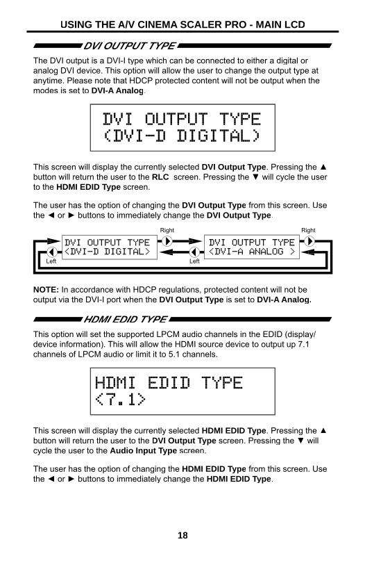
DVI OUTPUT TYPE The DVI output is a DVI-I type which can be connected to either a digital or analog DVI device. This option will allow the user to change the output type atanytime. Please note that HDCP protected content will not be output when the modes is set to DVI-A Analog.
This screen will display the currently selected DVI Output Type. Pressing the ▲button will return the user to the RLC screen. Pressing the ▼ will cycle the user to the HDMI EDID Type screen.
The user has the option of changing the DVI Output Type from this screen. Use the ◄ or ► buttons to immediately change the DVI Output Type.
NOTE: In accordance with HDCP regulations, protected content will not be output via the DVI-I port when the DVI Output Type is set to DVI-A Analog.
HDMI EDID TYPE This option will set the supported LPCM audio channels in the EDID (display/device information). This will allow the HDMI source device to output up 7.1channels of LPCM audio or limit it to 5.1 channels.
This screen will display the currently selected HDMI EDID Type. Pressing the ▲button will return the user to the DVI Output Type screen. Pressing the ▼ will cycle the user to the Audio Input Type screen.
The user has the option of changing the HDMI EDID Type from this screen. Use the ◄ or ► buttons to immediately change the HDMI EDID Type.

19
USING THE A/V CINEMA SCALER PRO - MAIN LCD
NOTE: This option will simply set the supported audio formats to include either 5.1 or 7.1 LPCM audio formats. The source must still be able to output these formats for this option to have any effect.
AUDIO INPUT TYPE Each input, excluding the HDMI input, supports multiple audio input types. This option will allow the user to select the desired audio type for each input. For acomplete listing of the supported formats for each input, please see page 14.
This screen will display the currently selected Audio Input Type. Pressing the▲ button will return the user to the HDMI EDID Type screen. Pressing the ▼ will cycle the user to the Product Title screen.
The user has the option of changing the Audio Input Type from this screen. Use the ◄ or ► buttons to immediately change the Audio Input Type.
NOTE: This option is not available on the HDMI and Bypass inputs. TheComponent 2 input does not have an OPTICAL audio input.

20
USING THE A/V CINEMA SCALER PRO - MAIN LCD
PRODUCT TITLE This screen will display the product title. Pressing the ▲ button will return theuser to the Output Screen. Pressing the ▼ will cycle the user to the Main Screen. Pressing the ◄ or ► buttons while on this screen will have no effect.

21
A/V CINEMA SCALER PRO - CONFIGURATION
MAIN FEATURES MENU
Once all connections have been made and a valid video input signal is detected, the Main Features Menu will become available. The following video/audioadjustment menus will also become available. From any of the information paneson the Main LCD screen, press the Menu button to enter the Main FeaturesMenu. Use the ◄ and ► buttons to cycle through the Main Features Menu. The following illustrates the order of the features and the cycling order.

22
A/V CINEMA SCALER PRO - CONFIGURATION
The following are the Main Features Menu items and short descriptions:
Picture Adjust Options in this menu include preset video settings and user adjustable video settings. Items such as brightness, contrast, and sharpness are found here.
Color Adjust Options in this menu control the appearance of white. Preset settings are available, as well as a user setting with manual control.
Lipsync Delay This menu will allow the user to apply a lip sync delay that is input specifi c. Settings made for one input will not affectanother input.
Surround Delay This menu will allow the user to apply a delay to each individual surround channel. Right surround, left surround, rear right surround, and rear left surround channel delay adjustments can be made. These settings are globaland will affect all output audio, no matter which input is selected.
Output Selection This menu will control which output resolution is used.
OSD Adjust This menu controls options for the on-screen display system. Items such as OSD-timeout and opacity are foundhere.
Firmware The fi rmware revision and build date are listed here.
NOTE: The following pages will strictly reference what the LCD Screen displays when adjusting options. The OSD will mirror the options and functions in thefollowing sections.
A/V CINEMA SCALER PRO - PICTURE ADJUST
The Picture Adjust menu will allow the user to select predefi ned picture modesthat will help enhance the fi nal video output. These presets will help by tuningthe output video to compensate for different lighting and viewing environments.Presets can be bypassed by using the User setting. Once the User setting hasbeen selected all individual options become modifi able.
To enter the Picture Adjust menu use the ◄ and ► buttons from the Main Features Menu to select Picture Adjust. Use the ▼ or Select button to enter the menu. The following page illustrates all possible options that are available in the Picture Adjust menu for all inputs.
NOTE: Some menu items will be input specifi c and will not appear in other inputmenu. All adjustments in this menu are global for all inputs except Bypass Mode.

23
A/V CINEMA SCALER PRO - CONFIGURATION
Menu for HDMI, DVI-D andDVI-I (Digital Portion) Inputs
Menu for Component Inputs Menu for VGA andDVI-I (Analog Portion) Inputs
MODE The preset picture modes are selectable with this option. Preset contrast, brightness, hue, saturation, and sharpness settings are stored for each mode. When the mode is switched to User all individual options will be available for radjustment.
To cycle between the modes, use the ◄ or ► or Select buttons. The change willbe immediate and no other buttons need to be pressed to confi rm the change. The modes and cycle order is listed on the next page.

24
A/V CINEMA SCALER PRO - CONFIGURATION
The preset modes are listed below:
Standard Useful for general content
Movie Useful for dimly lit environments
Vivid Useful for accentuating colors for a more vibrant image
User User confi gured settingsr
Once the User mode is selected, additional options will become available. Usethe ▼ button to select the next option. Use the ▲ option to return to the previous option.
CONTRAST This option will set the contrast level for the output video signal.
Press the ◄ or ► or Select buttons to begin adjusting this option. A < and > character will surround the numerical value to signify that user adjustment can begin. Use the ◄ and ► to adjust the value of this option. When adjustments arecomplete, press the Select button to save. Use the ▼ button to select the next option. Use the ▲ option to return to the previous option.

25
A/V CINEMA SCALER PRO - CONFIGURATION
BRIGHTNESS This option will set the brightness level for the output video signal.
Press the ◄ or ► or Select buttons to begin adjusting this option. A < and > character will surround the numerical value to signify that user adjustment can begin. Use the ◄ and ► to adjust the value of this option. When adjustments arecomplete, press the Select button to save. Use the ▼ button to select the next option. Use the ▲ option to return to the previous option.
HUE This option will set the hue balance for the output video signal. This option will not be available when the VGA or DVI-I (Analog portion) input is selected.
Press the ◄ or ► or Select buttons to begin adjusting this option. A < and > character will surround the numerical value to signify that user adjustment can begin. Use the ◄ and ► to adjust the value of this option. When adjustments arecomplete, press the Select button to save. Use the ▼ button to select the next option. Use the ▲ option to return to the previous option.
SATURATION This option will set the saturation level for the output video signal. This option will not be available when the VGA or DVI-I (Analog portion) input is selected.
Press the ◄ or ► or Select buttons to begin adjusting this option. A < and > character will surround the numerical value to signify that user adjustment can begin. Use the ◄ and ► to adjust the value of this option. When adjustments arecomplete, press the Select button to save. Use the ▼ button to select the next option. Use the ▲ option to return to the previous option.

26
A/V CINEMA SCALER PRO - CONFIGURATION
SHARPNESS This option will set the sharpness level for the output video signal. This option will not be available when the VGA or DVI-I (Analog portion) input is selected.
Press the ◄ or ► or Select buttons to begin adjusting this option. A < and > character will surround the numerical value to signify that user adjustment can begin. Use the ◄ and ► to adjust the value of this option. When adjustments arecomplete, press the Select button to save. Use the ▼ button to select the next option. Use the ▲ option to return to the previous option.
ASPECT RATIO The aspect ratio of the output video is set with this option. There are 5 aspect ration modes to choose from.
To cycle between the aspect ratio modes, use either the ◄ or ► or Selectbuttons. The change will be immediate and no other buttons need to be pressedto confi rm the change. The aspect ratio modes and cycle order is listed below.

27
A/V CINEMA SCALER PRO - CONFIGURATION
The aspect ratio modes are listed below:
Full Stretches the image to fi ll the screen
Overscan Stretches the image to just beyond the border of the outputresolution (a portion of the image may be cropped)
Underscan Stretches the image to just within the border of the outputresolution (a black border will appear around the outside edges)
Letterbox Stretches the image to 16:9 aspect ratio without underscan
Panscan Stretches the image to 4:3 aspect ratio without underscan
Please use the examples below do determine which aspect ratio mode shouldbe used. Please pay attention to the appearance of the circles. All circles that appear as ovals will result in an output image that appears stretched/Compressed.

28
A/V CINEMA SCALER PRO - CONFIGURATION
Use the ▼ button to select the next option. Use the ▲ option to return to theprevious option.
NOISE REDUCTION This option will allow the user to apply a noise reduction fi lter to the component video input sources. This option will only be available when the input source is component video. The noise reduction fi lter reduces noise that commonlyappears in analog video sources. There are 4 settings to choose from.
To cycle between the noise reduction settings, use either the ◄ or ► or Select buttons. The change will be immediate and no other buttons need to be pressedto confi rm the change. The aspect ratio modes and cycle order are listed below.
The noise reduction modes are listed below:
Off Noise reduction is offf
Low Low level video noise reduction is applied
Middle Moderate level video noise reduction
High High level video noise reduction (may cause a slight ghostingeffect on objects)
Use the ▼ button to select the next option. Use the ▲ option to return to theprevious option.

29
A/V CINEMA SCALER PRO - CONFIGURATION
HORIZONTAL POSITION This option will set the horizontal position of the video image in relation to the output border. This option is only available when using the VGA or DVI-I (Analogportion) inputs.
Press the ◄ or ► or Select buttons to begin adjusting this option. A < and > character will surround the numerical value to signify that user adjustment can begin. Use the ◄ and ► to adjust the value of this option. When adjustments arecomplete, press the Select button to save. Use the ▼ button to select the next option. Use the ▲ option to return to the previous option.
VERTICAL POSITION This option will set the vertical position of the video image in relation to the output border. This option is only available when using the VGA or DVI-I (Analogportion) inputs.
Press the ◄ or ► or Select buttons to begin adjusting this option. A < and > character will surround the numerical value to signify that user adjustment can begin. Use the ◄ and ► to adjust the value of this option. When adjustments arecomplete, press the Select button to save. Use the ▼ button to select the next option. Use the ▲ option to return to the previous option.
CLOCK This option will adjust the clock timing to enable the user to adjust the videoimage. This option is only available when using the VGA or DVI-I (Analog portion) inputs.
Press the ◄ or ► or Select buttons to begin adjusting this option. A < and > character will surround the numerical value to signify that user adjustment can begin. Use the ◄ and ► to adjust the value of this option. When adjustments arecomplete, press the Select button to save. Use the ▼ button to select the next option. Use the ▲ option to return to the previous option.

30
A/V CINEMA SCALER PRO - CONFIGURATION
PHASE This option will adjust the phase to enable the user to adjust the video image. This option is only available when using the VGA or DVI-I (Analog portion) inputs.
Press the ◄ or ► or Select buttons to begin adjusting this option. A < and > character will surround the numerical value to signify that user adjustment can begin. Use the ◄ and ► to adjust the value of this option. When adjustments arecomplete, press the Select button to save. Use the ▼ button to select the next option. Use the ▲ option to return to the previous option.
EXIT PICTURE ADJUST This option will return the user to the Main Features Menu.
To return to the Main Features Menu press the Select button. Pressing the ▼button will cycle to the Mode option. Use the ▼ button to select the next option. Use the ▲ option to return to the previous option.
A/V CINEMA SCALER PRO - COLOR ADJUST
The Color Adjust menu will allow the user to select predefi ned settings for theappearance of white (color temperature). Presets can be bypassed by using the User setting. Once the User setting has been selected all individual optionsbecome modifi able.
To enter the Color Adjust menu use the ◄ and ► buttons from the MainFeatures Menu to select Color Adjust. Use the ▼ or Select button to enter the menu. The following page illustrates all possible options that are available in the Color Adjust menu.

31
A/V CINEMA SCALER PRO - CONFIGURATION
COLOR ADJUST MENU OPTIONS
COLOR TEMP The preset color temperature modes are selectable with this option. Preset red,green, and blue settings are stored in each mode. When the mode is switched toUser all individual options will be available for adjustment.r
To cycle between the modes, use the ◄ or ► or Select buttons. The change willbe immediate and no other buttons need to be pressed to confi rm the change. The modes and cycle order is listed are listed on the following page.
These Options areonly available whenthe User mode is rselected

32
A/V CINEMA SCALER PRO - CONFIGURATION
The preset color temperature settings are listed below:
Normal Colors/white will be neutral. White should not have an overly red or blue appearance.
Warm Colors/white will have a slightly red appearance.
Cool Colors/white will have a slightly blue appearance.
User User confi gured settingsr
Once the User mode is selected, additional options will become available. Usethe ▼ button to select the next option. Use the ▲ option to return to the previous option.
RED This option will set the amount of red in the output video signal.
Press the ◄ or ► or Select buttons to begin adjusting this option. A < and > character will surround the numerical value to signify that user adjustment can begin. Use the ◄ and ► to adjust the value of this option. When adjustments arecomplete, press the Select button to save. Use the ▼ button to select the next option. Use the ▲ option to return to the previous option.

33
A/V CINEMA SCALER PRO - CONFIGURATION
GREEN This option will set the amount of green in the output video signal.
Press the ◄ or ► or Select buttons to begin adjusting this option. A < and > character will surround the numerical value to signify that user adjustment can begin. Use the ◄ and ► to adjust the value of this option. When adjustments arecomplete, press the Select button to save. Use the ▼ button to select the next option. Use the ▲ option to return to the previous option.
BLUE This option will set the amount of blue in the output video signal.
Press the ◄ or ► or Select buttons to begin adjusting this option. A < and > character will surround the numerical value to signify that user adjustment can begin. Use the ◄ and ► to adjust the value of this option. When adjustments arecomplete, press the Select button to save. Use the ▼ button to select the next option. Use the ▲ option to return to the previous option.
EXIT COLOR ADJUST This option will return the user to the Main Features Menu.
This option will return the user to the Main Features Menu. To return to the Main Features Menu press the Select button. Pressing the ▼ button will cycle to the Color Temp option. Use the ▼ button to select the next option. Use the ▲ option to return to the previous option.

34
A/V CINEMA SCALER PRO - CONFIGURATION
A/V CINEMA SCALER PRO - LIPSYNC DELAY ADJUST
The Lipsync Delay Adjust menu will allow the user to apply a lip sync delay that is useful for correcting errors in synchronization between the audio and video. This delay has a maximum correction time of 80 milliseconds. Each input can have a separate lip sync adjustment value. This adjustment will not affect audio delay when in the Bypass Mode.
To enter the Lipsync Delay Adjust menu use the ◄ and ► buttons from the Main Features Menu to select Lipsync Delay Adjust. Use the ▼ or Select button to enter the menu. There is only one option in this menu.
LIPSYNC DELAY This option will set the lip sync delay for the currently selected input.
Pressing the ► or Select buttons will advance the delay by 5 millisecond increments. Pressing the ◄ button will reduce the delay by 5 milliseconds. Themaximum delay available is 80 milliseconds. Use the ▼ or ▲ button to select the Exit LipSync Adjust option.
EXIT LIPSYNC ADJUST This option will return the user to the Main Features Menu.
This option will return the user to the Main Features Menu. To return to the Main Features Menu press the Select button. Pressing the ▼ or ▲ button will return the user to the LipSync Delay option.

35
A/V CINEMA SCALER PRO - CONFIGURATION
A/V CINEMA SCALER PRO - SURROUND DELAY ADJUST
The Surround Delay Adjust menu will allow the user to apply a delay tocompensate for the distance between the main and surround audio channels. Each surround delay has a maximum correction time of 150 milliseconds. Thesettings in this menu option are global and will affect the surround channels for every input. This adjustment will not affect audio delay when in the Bypass Mode.
To enter the Surround Delay Adjust menu use the ◄ and ► buttons from theMain Features Menu to select Surround Delay Adjust. Use the ▼ or Selectbutton to enter the menu. The following illustrates all possible options that areavailable in the Surround Delay Adjust menu.
SURROUND RIGHT DELAY This option will set the surround delay for the surround right channel.
When this option is selected, pressing the ► or Select buttons will advance thedelay by 5 millisecond increments. Pressing the ◄ button will reduce the delay by 5 milliseconds. The maximum delay available is 150 milliseconds. Use the ▼button to select the next option. Use the ▲ option to return to the previous option.

36
A/V CINEMA SCALER PRO - CONFIGURATION
SURROUND LEFT DELAY This option will set the surround delay for the surround left channel.
When this option is selected, pressing the ► or Select buttons will advance thedelay by 5 millisecond increments. Pressing the ◄ button will reduce the delayby 5 milliseconds. The maximum delay available is 150 milliseconds. Use the ▼button to select the next option. Use the ▲ option to return to the previous option.
REAR SURROUND RIGHT DELAY This option will set the surround delay for the rear surround right channel.
When this option is selected, pressing the ► or Select buttons will advance thedelay by 5 millisecond increments. Pressing the ◄ button will reduce the delayby 5 milliseconds. The maximum delay available is 150 milliseconds. Use the ▼button to select the next option. Use the ▲ option to return to the previous option.
REAR SURROUND LEFT DELAY This option will set the surround delay for the rear surround left channel.
When this option is selected, pressing the ► or Select buttons will advance thedelay by 5 millisecond increments. Pressing the ◄ button will reduce the delayby 5 milliseconds. The maximum delay available is 150 milliseconds. Use the ▼button to select the next option. Use the ▲ option to return to the previous option.
EXIT LIPSYNC ADJUST This option will return the user to the Main Features Menu.
This option will return the user to the Main Features Menu. To return to the Main Features Menu press the Select button. Use the ▼ button to select the next option. Use the ▲ option to return to the previous option.

37
A/V CINEMA SCALER PRO - CONFIGURATION
A/V CINEMA SCALER PRO - OUTPUT SELECTION
The Output Selection menu will allow the user to select the output video resolution.
To enter the Output Selection menu use the ◄ and ► buttons from the MainFeatures Menu to select Output Selection. Use the ▼ or Select button to enter the menu. The following illustrates all possible options that are available in the Output Selection menu.
OUTPUT TIMING 1080P This option will change the output resolution to a progressive 1920x1080 at 60Hz signal. All input formats will be scaled to this resolution.
Press the Select button to set this resolution. The change will be immediate. Pressing the ▼ button will cycle to the Output Timing 2K option. Use the ▼button to select the next option. Use the ▲ option to return to the previous option.

38
OUTPUT TIMING 2K This option will change the output resolution to a progressive 2048x1080 at 60Hz signal. All input formats will be scaled to this resolution.
Press the Select button to set this resolution. The change will be immediate. Pressing the ▼ button will cycle to the Exit Output Selection option. Use the ▼button to select the next option. Use the ▲ option to return to the previous option.
EXIT OUTPUT SELECTION This option will return the user to the Main Features Menu.
This option will return the user to the Main Features Menu. To return to the Main Features Menu press the Select button. Use the ▼ button to select the next option. Use the ▲ option to return to the previous option.
A/V CINEMA SCALER PRO - ON SCREEN DISPLAY ADJUST
The On Screen Display Adjust menu will allow the user to set options relatedto the on-screen display. Horizontal and vertical alignment, opacity, and time-outsettings are found here.
To enter the On Screen Display Adjust menu use the ◄ and ► buttons fromthe Main Features Menu to select On Screen Display Adjust. Use the ▼or Select button to enter the menu. The following page illustrates all possibleoptions that are available in the On Screen Display Adjust menu.
A/V CINEMA SCALER PRO - CONFIGURATION

39
A/V CINEMA SCALER PRO - CONFIGURATION
HORIZONTAL POSITION This option will change the horizontal position of the on-screen display.
Press the ◄ or ► or Select buttons to begin adjusting this option. A < and > character will surround the numerical value to signify that user adjustment can begin. Use the ◄ and ► to adjust the value of this option. When adjustments arecomplete, press the Select button to save. Use the ▼ button to select the next option. Use the ▲ option to return to the previous option.

40
VERTICAL POSITION This option will change the vertical position of the on-screen display.
Press the ◄ or ► or Select buttons to begin adjusting this option. A < and > character will surround the numerical value to signify that user adjustment can begin. Use the ◄ and ► to adjust the value of this option. When adjustments arecomplete, press the Select button to save. Use the ▼ button to select the next option. Use the ▲ option to return to the previous option.
TIMEOUT This option will change the amount of idle time before the on-screen displayreturns to the Main Screen.
Press the ◄ or ► or Select buttons to begin adjusting this option. A < and > character will surround the numerical value to signify that user adjustment can begin. Use the ◄ and ► to adjust the value of this option. When adjustments arecomplete, press the Select button to save. Use the ▼ button to select the next option. Use the ▲ option to return to the previous option.
BACKGROUND This option will change the opacity level of the on-screen display.
Press the ◄ or ► or Select buttons to begin adjusting this option. A < and > character will surround the numerical value to signify that user adjustment can begin. Use the ◄ and ► to adjust the value of this option. When adjustments arecomplete, press the Select button to save. Use the ▼ button to select the next option. Use the ▲ option to return to the previous option.
A/V CINEMA SCALER PRO - CONFIGURATION

41
A/V CINEMA SCALER PRO - CONFIGURATION
EXIT OSD ADJUST This option will return the user to the Main Features Menu.
This option will return the user to the Main Features Menu. To return to the Main Features Menu press the Select button. Use the ▼ button to select the next option. Use the ▲ option to return to the previous option.
A/V CINEMA SCALER PRO - FIRMWARE
The Firmware option will simply display the current fi rmware that is runningon the A/V Cinema Scaler Pro. This information may be needed when calling technical support.

42
DB-25 AUDIO INPUT & BYPASS MODE
A/V CINEMA SCALER PRO - DB-25 AUDIO BYPASS MODE
The A/V Cinema Scaler Pro can accept high quality 8 channel analog audio via the DB-25 input located on the back panel. This input is only accessible from the bypass mode. The audio through this input will be directly passed to the analog DB-25 output.
ENABLING BYPASS MODE To enable the bypass mode, locate the bypass mode button on the front panel.From the Main Screen press the Bypass button on the front panel to enable thebypass mode. The bypass mode will cycle in the following order. Each button press will progress to the next option.
Please note that there will be NO VIDEO OUTPUT when using the bypassfunction.
Main Screen
Analog DB-25 Input

43
ANALOG INPUT AND OUTPUT PINOUT

44
ANALOG INPUT AND OUTPUT PINOUT
Pin Function1 Left Negative Input
2 Right Surround Positive Input
3 Right Surround Negative Input
4 Left Surround Negative Input
5 Right Extra Negative Input
6 Right Negative Input
7 Left Extra Negative Input
8 Center Negative Input
9 Chassis GND
10 Chassis GND
11 Chassis GND
12 Subwoofer Negative Input
13 Chassis GND
14 Left Positive Input
Pin Function15 Left Surround Positive Input
16 Right Extra Positive Input
17 Right Positive Input
18 Left Extra Positive Input
19 Chassis GND
20 Center Positive Input
21 Tied to Output
22 NC
23 NC
24 Subwoofer Positive Input (band-limited to 300Hz in DigitalMedia mode)
25 Tied to Output
Pin Function
1 Left Negative Output
2 Right Surround Positive Output
3 Right Surround Negative Output
4 Left Surround Negative Output
5 Right Extra Negative Output
6 Right Negative Output
7 Left Extra Negative Output
8 Center Negative Output
9 Chassis GND
10 Chassis GND
11 Chassis GND
12 Subwoofer Negative Output
13 Chassis GND
14 Left Positive Output
Pin Function
15 Left Surround Positive Output
16 Right Extra Positive Output
17 Right Positive Output
18 Left Extra Positive Output
19 Chassis GND
20 Center Positive Output
21 Tied to Input
22 NC
23 NC
24 Subwoofer Positive Output (band-limited to 300Hz in DigitalMedia mode)
25 Tied to Input
ANALOG DB-25 OUTPUT
ANALOG DB-25 INPUT

45
RS-232 SERIAL CONTROL INTERFACE
RS-232 SETTINGS RS 232 SETTINGS
Bits per second ................................................................................................. 19200
Data bits .................................................................................................................... 8
Parity .................................................................................................................. None
Stop bits .....................................................................................................................1
Flow Control ....................................................................................................... None

46
RS-232 SERIAL CONTROL COMMANDS
Set CommandsCommand Code Response DescriptionS SOURCE 0 > SOURCE HDMI HDMIS SOURCE 1 > SOURCE DVI1 DVI1S SOURCE 2 > SOURCE DVI2 DVI2S SOURCE 3 > SOURCE YPbPr2 YPbPr2S SOURCE 4 > SOURCE YPbPr1 YPbPr1S SOURCE 5 > SOURCE PC PCS SOURCE 6 > SOURCE ANALOG_BYPASS Analog BypassS SOURCE 7 > SOURCE DIGITAL_BYPASS Digital Bypass(if available<---H/W exist)S AUDIO 0 > AUDIO Stereo Audio-Input select to Analog (Stereo)S AUDIO 1 > AUDIO Coaxial Audio-Input select to Digital (Coaxial)S AUDIO 2 > AUDIO Optical Audio-Input select to Digital (Optical)REBOOT Soft Reboot MachineS OUTPUT 10 > OUTPUT 1080P60 1080P 60HZ RESOLUTION OUTPUTS OUTPUT 19 > OUTPUT 2K 2K RESOLUTION OUTPUTS SIZE 0 > SIZE FULL SCALER FULL OUTPUTS SIZE 1 > SIZE OVERSCAN SCALER OVERSCAN OUTPUTS SIZE 2 > SIZE UNDERSCAN SCALER UNDERSCAN OUTPUTS SIZE 3 > SIZE LETTERBOX SCALER LETTERBOX OUTPUTS SIZE 4 > SIZE PANSCAN SCALER PANSCAN OUTPUT
S PICTUREMODE 0~3 > PICTUREMODE STANDARD~USER
0:STANDARD ; 1:MOVIE ; 2:VIVID ; 3:USER ,PICTURE MODE OUTPUT
S CONTRAST 0~100 > CONTRAST 0~100 CONTRAST 0~100 ADJUST [Defaut:50]S BRIGHTNESS 0~100 > BRIGHTNESS 0~100 BRIGHTNESS 0~100 ADJUST [Defaut:45]S HUE 0~100 > HUE 0~100 HUE 0~100 ADJUST [Defaut:50]S SATURATION 0~100 > SATURATION 0~100 SATURATION 0~100 ADJUST [Defaut:60]S SHARPNESS 0~100 > SHARPNESS 0~100 SHARPNESS 0~100 ADJUST [Defaut:32]
S NR 0~3 > NR OFF~HIGH 0:OFF ; 1:LOW ; 2:MIDDLE ; 3:HIGH ,NR CONTROL
S PCHPOSITION 0~100 > PCHPOSITION 0~100 H POSITION 0~100 ADJUSTS PCVPOSITION 0~100 > PCVPOSITION 0~100 V POSITION 0~100 ADJUSTS PCCLOCK 0~100 > PCCLOCK 0~100 PC MODE COLCK 0~100 ADJUSTS PCPHASE 0~63 > PCPHASE 0~63 PC MODE PHASE 0~63 ADJUST
S COLORTEMP 0~3 > COLORTEMP NORMAL~USER 0:NORMAL ; 1:WARM ; 2:COOL ; 3:USER ,COLORTEMP SETTING
S RED 0~100 > RED 0~100 COLOR TEMP "RED" ADJUST [Defaut:47][ ]
S GREEN 0~100 > GREEN 0~100 COLOR TEMP "GREEN" ADJUST [Defaut:47][ ]
S BLUE 0~100 > BLUE 0~100 COLOR TEMP "BLUE" ADJUST [Defaut:47][ ]
S OSDHPOSITION 0~100 > OSDHPOSITION 0~100 OSD H POSITION 0~100 ADJUST [Defaut:50][ ]
S OSDVPOSITION 0~100 > OSDVPOSITION 0~100 OSD V POSITION 0~100 ADJUST [Defaut:50][ ]
S OSDTIMEOUT 0~100 > OSDTIMEOUT 0~100 OSD TIMEOUT 0~100 SETTING [Defaut:10][ ]
S OSDBACKGROUND 0~8 > OSDBACKGROUND 0~8 OSD OSDBACKGROUND 0~8 ADJUST [Defaut:5]S RESET 1 > RESET ON RESET ACTIONS OSDNOTICE 0 > OSDNOTICE ENABLE ON SCREEN MENU is ONS OSDNOTICE 1 > OSDNOTICE DISABLE ON SCREEN MENU is OFFAUDIO_DATA AUDIO INFO. Like LCM shownPLIION > PLII IS ON DOLBY PROLOGICII PROCESSING ONPLIIOFF > PLII IS OFF DOLBY PROLOGICII PROCESSING OFFDRCON > DRC IS ON DYNAMIC RANGE CONTROL ONDRCOFF > DRC IS OFF DYNAMIC RANGE CONTROL OFFRLCON > RLC IS ON REFERENCE LEVEL COMP. ONRLCOFF > RLC IS OFF REFERENCE LEVEL COMP. OFFDVIA > DVI-A ANALOG DVI OUTPUT TYPE IS DVI-A ANALOGDVID > DVI-D DIGITAL DVI OUTPUT TYPE IS DVI-D DIGITALEDID51 > EDID 5.1 HDMI EDID TYPE 5.1

47
RS-232 SERIAL CONTROL COMMANDS
EDID71 > EDID 7.1 HDMI EDID TYPE 7.1VGA_AUTO > AutoConfi g VGA MODE AutoConfi g
DVI? > DVI-D DIGITAL or DVI-A ANALOG SHOW DVI-D DIGITAL or DVI-A ANALOG
AUDSRC? > AUDIO SRC=ANALOG or COAXor OPTICAL
SHOW AUDIO SRC=ANALOG or COAX or OPTICAL
INFO > EXT-AVCINEMAA 3.2107/02/2010 SHOW Latest F/W and date when F/W updated.
Status CommandsCommand Code Response DescriptionR OUTPUT > OUTPUT NATIVE~2K SHOW OUTPUT STATUSR SOURCE > SOURCE HDMI SHOW SOURCE STATUSR SIZE > SIZE FULL~PANSCAN SHOW SIZE STATUSR PICTUREMODE > PICTUREMODE STANDARD~USER SHOW PICTURE MODE STATUSR CONTRAST > CONTRAST 0~100 SHOW CONTRAST STATUSR BRIGHTNESS > BRIGHTNESS 0~100 SHOW BRIGHTNESS STATUSR HUE > HUE 0~100 SHOW HUE STATUSR SATURATION > SATURATION 0~100 SHOW SATURATION STATUSR SHARPNESS > SHARPNESS 0~100 SHOW SHARPNESS STATUSR NR > NR OFF~HIGH SHOW NR STATUSR PCHPOSITION > PCHPOSITION 0~100 SHOW PC H-POSITION STATUSR PCVPOSITION > PCVPOSITION 0~100 SHOW PC V-POSITION STATUSR PCCLOCK > PCCLOCK 0~100 SHOW PC COLOK STATUSR PCPHASE > PCPHASE 0~63 SHOW PC PHASE STATUSR COLORTEMP > COLORTEMP NORMAL~USER SHOW COLOR TEMP STATUS
NOTE: When using the Bypass Modes the only available commands are:
• S SOURCE commands• R SOURCE command• INFO command
48
RACK MOUNT / TABLETOP INSTALLATION
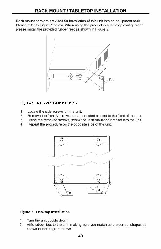
Rack mount ears are provided for installation of this unit into an equipment rack.Please refer to Figure 1 below. When using the product in a tabletop confi guration,please install the provided rubber feet as shown in Figure 2.
*3PCS
BB
B
AA
A
1. Locate the side screws on the unit.2. Remove the front 3 screws that are located closest to the front of the unit.3. Using the removed screws, screw the rack mounting bracket into the unit.4. Repeat the procedure on the opposite side of the unit.
Figure 2. Desktop Installation
1. Turn the unit upside down.2. Affi x rubber feet to the unit, making sure you match up the correct shapes as
shown in the diagram above.

49
Video SectionInput ConnectorsHDMI 1 – Type A 19pin FemaleVGA 1 – HD-15 FemaleDVI-I 1 – DVI-I 29pin FemaleDVI-D 1 – DVI-I 29pin Female (Digital)Component 2 – 3 RCA
Input Resolutions640x480 (60Hz)HDMI/DVI-I/DVI-D/VGA800x600 (60Hz)HDMI/DVI-I/DVI-D/VGA1024x768 (60Hz)HDMI/DVI-I/DVI-D/VGA1152x864 (60Hz)HDMI/DVI-I/DVI-D/VGA1280x800 (60Hz)HDMI/DVI-I/DVI-D/VGA1360x768 (60Hz)HDMI/DVI-I/DVI-D/VGA1280x960 (60Hz)HDMI/DVI-I/DVI-D/VGA1600x1200 (60Hz)HDMI/DVI-I/DVI-D/VGA1920x1200 (60Hz)HDMI/DVI-I/DVI-D/VGA720x480i (59/60Hz)HDMI/Component/DVI-D720x480p (59/60Hz)HDMI/Component/DVI-D720x576i (50Hz)HDMI/Component/DVI-D720x576p (50Hz)HDMI/Component/DVI-D1280x720p (50/60Hz)HDMI/Component/DVI-D1920x1080i (50/60Hz)HDMI/Component/DVI-D1920x1080p (25/29/30/50/59/60Hz)HDMI/ Component/DVI-D1920x1080p (24Hz)HDMI/DVI-D (Passthough)
Output ConnectorsDVI-I (DVI-A/DVI-D Switchable) 1
Output Resolutions1920x1080p (23.97/24/50/60Hz) DVI-I2048x1080p (23.97/24/50/60Hz) DVI-I
Component Input Sensitivity 1 Vp-p
HDMI Compliancy 1.2
HDCP Compliant Yes
Input ColorspaceHDMI RGB/YCbCrVGA RGBHVDVI-I RGBHV/RGBDVI-D RGBComponent YPbPr
Output Colorspace RGB
SPECIFICATIONS

50
SPECIFICATIONS
Audio SectionInput ConnectorsHDMI 1RCA Type Analog L/R 5 (1 per input excluding HDMI)Digital Coaxial 5 (1 per input excluding HDMI)Analog DB-25 1
Output ConnectorsAnalog DB-25 1
THD < 0.001%
Stereo Input Max Voltage 2Vrms
Output LevelFrom Digital Source -20dBFS 350mVrmsFrom Analog Source 0dBFS 3.5Vrms
Frequency Response < ± 0.5dB
Signal-To-Noise Ratio*Analog L/R Input >90dBDigital Input >100dBAnalog DB-25 Input >110dB
*20Hz-20kHz A weight fi lter, reference to full scale output of 3.5VrmsCoaxial Digital Audio Format Support2 Channel LPCM 32kHz – 96kHzMulti-Channel AC-3 2-6 Channels Bitstream
HDMI Digital Audio Format Support2 Channel LPCM 32kHz – 96kHzMulti-Channel AC-3 2-6 Channels Bitstream8 Channel LPCM 32kHz - 96kHz
Audio ProcessingDolby Pro Logic II* All analog/digital inputs
*Analog DB-25 audio inputs bypass all audio processing

51
SPECIFICATIONS
General Specifi cationsOperating Temperature 10 - 40° C Non-Condensing/Low Humidity
Control Terminal RS-232 Serial Communications
Dimensions 16.9” W x 1.7”H x 8”D
Package Dimensions 18.5” W x 4.5”H x 12”D
Rack Mountable 1.5U (Rack Ears Included)
Shipping/Unit Weight Estimate 12 lbs./ 9 lbs. (Final TBD)
PowerUniversal Power Supply 100-240Vac, 50/60HzPower Output 12VdcPower Consumption 6.67A (80 Watts Max)

52
Gefen warrants the equipment it manufactures to be free from defects in material and workmanship.
If equipment fails because of such defects and Gefen is notifi ed within two (2) years from the date of shipment, Gefen will, at its option, repair or replace theequipment, provided that the equipment has not been subjected to mechanical, electrical, or other abuse or modifi cations. Equipment that fails under conditions other than those covered will be repaired at the current price of parts and labor ineffect at the time of repair. Such repairs are warranted for ninety (90) days fromthe day of reshipment to the Buyer.
This warranty is in lieu of all other warranties expressed or implied, including without limitation, any implied warranty or merchantability or fi tness for any particular purpose, all of which are expressly disclaimed.
1. Proof of sale may be required in order to claim warranty.
2. Customers outside the US are responsible for shipping charges to and fromGefen.
3. Copper cables are limited to a 30 day warranty and cables must be in their original condition.
The information in this manual has been carefully checked and is believed tobe accurate. However, Gefen assumes no responsibility for any inaccuracies that may be contained in this manual. In no event will Gefen be liable for direct, indirect, special, incidental, or consequential damages resulting fromany defect or omission in this manual, even if advised of the possibility of such damages. The technical information contained herein regarding the features and specifi cations is subject to change without notice.
For the latest warranty coverage information, refer to the Warranty and Return Policy under the Support section of the Gefen Web site at www.gefen.com.
PRODUCT REGISTRATION
Please register your product online by visiting the Register Product page under the Support section of the Gefen Web site.
WARRANTY


Rev E33.25
20600 Nordhoff St., Chatsworth CA 91311
1-800-545-6900 818-772-9100 fax: 818-772-9120
www.gefen.com [email protected]
Pb
This product uses UL listed power supplies.